EP3680578A1 - Heat pump system and air conditioner - Google Patents
Heat pump system and air conditioner Download PDFInfo
- Publication number
- EP3680578A1 EP3680578A1 EP19801655.2A EP19801655A EP3680578A1 EP 3680578 A1 EP3680578 A1 EP 3680578A1 EP 19801655 A EP19801655 A EP 19801655A EP 3680578 A1 EP3680578 A1 EP 3680578A1
- Authority
- EP
- European Patent Office
- Prior art keywords
- valve
- heat exchanger
- valve port
- heating
- heat
- Prior art date
- Legal status (The legal status is an assumption and is not a legal conclusion. Google has not performed a legal analysis and makes no representation as to the accuracy of the status listed.)
- Granted
Links
Images


Classifications
-
- F—MECHANICAL ENGINEERING; LIGHTING; HEATING; WEAPONS; BLASTING
- F25—REFRIGERATION OR COOLING; COMBINED HEATING AND REFRIGERATION SYSTEMS; HEAT PUMP SYSTEMS; MANUFACTURE OR STORAGE OF ICE; LIQUEFACTION SOLIDIFICATION OF GASES
- F25B—REFRIGERATION MACHINES, PLANTS OR SYSTEMS; COMBINED HEATING AND REFRIGERATION SYSTEMS; HEAT PUMP SYSTEMS
- F25B13/00—Compression machines, plants or systems, with reversible cycle
-
- F—MECHANICAL ENGINEERING; LIGHTING; HEATING; WEAPONS; BLASTING
- F25—REFRIGERATION OR COOLING; COMBINED HEATING AND REFRIGERATION SYSTEMS; HEAT PUMP SYSTEMS; MANUFACTURE OR STORAGE OF ICE; LIQUEFACTION SOLIDIFICATION OF GASES
- F25B—REFRIGERATION MACHINES, PLANTS OR SYSTEMS; COMBINED HEATING AND REFRIGERATION SYSTEMS; HEAT PUMP SYSTEMS
- F25B29/00—Combined heating and refrigeration systems, e.g. operating alternately or simultaneously
- F25B29/003—Combined heating and refrigeration systems, e.g. operating alternately or simultaneously of the compression type system
-
- F—MECHANICAL ENGINEERING; LIGHTING; HEATING; WEAPONS; BLASTING
- F25—REFRIGERATION OR COOLING; COMBINED HEATING AND REFRIGERATION SYSTEMS; HEAT PUMP SYSTEMS; MANUFACTURE OR STORAGE OF ICE; LIQUEFACTION SOLIDIFICATION OF GASES
- F25B—REFRIGERATION MACHINES, PLANTS OR SYSTEMS; COMBINED HEATING AND REFRIGERATION SYSTEMS; HEAT PUMP SYSTEMS
- F25B41/00—Fluid-circulation arrangements
- F25B41/20—Disposition of valves, e.g. of on-off valves or flow control valves
-
- F—MECHANICAL ENGINEERING; LIGHTING; HEATING; WEAPONS; BLASTING
- F25—REFRIGERATION OR COOLING; COMBINED HEATING AND REFRIGERATION SYSTEMS; HEAT PUMP SYSTEMS; MANUFACTURE OR STORAGE OF ICE; LIQUEFACTION SOLIDIFICATION OF GASES
- F25B—REFRIGERATION MACHINES, PLANTS OR SYSTEMS; COMBINED HEATING AND REFRIGERATION SYSTEMS; HEAT PUMP SYSTEMS
- F25B47/00—Arrangements for preventing or removing deposits or corrosion, not provided for in another subclass
- F25B47/02—Defrosting cycles
-
- F—MECHANICAL ENGINEERING; LIGHTING; HEATING; WEAPONS; BLASTING
- F25—REFRIGERATION OR COOLING; COMBINED HEATING AND REFRIGERATION SYSTEMS; HEAT PUMP SYSTEMS; MANUFACTURE OR STORAGE OF ICE; LIQUEFACTION SOLIDIFICATION OF GASES
- F25B—REFRIGERATION MACHINES, PLANTS OR SYSTEMS; COMBINED HEATING AND REFRIGERATION SYSTEMS; HEAT PUMP SYSTEMS
- F25B47/00—Arrangements for preventing or removing deposits or corrosion, not provided for in another subclass
- F25B47/02—Defrosting cycles
- F25B47/022—Defrosting cycles hot gas defrosting
- F25B47/025—Defrosting cycles hot gas defrosting by reversing the cycle
-
- F—MECHANICAL ENGINEERING; LIGHTING; HEATING; WEAPONS; BLASTING
- F25—REFRIGERATION OR COOLING; COMBINED HEATING AND REFRIGERATION SYSTEMS; HEAT PUMP SYSTEMS; MANUFACTURE OR STORAGE OF ICE; LIQUEFACTION SOLIDIFICATION OF GASES
- F25B—REFRIGERATION MACHINES, PLANTS OR SYSTEMS; COMBINED HEATING AND REFRIGERATION SYSTEMS; HEAT PUMP SYSTEMS
- F25B2313/00—Compression machines, plants or systems with reversible cycle not otherwise provided for
- F25B2313/008—Refrigerant heaters
-
- F—MECHANICAL ENGINEERING; LIGHTING; HEATING; WEAPONS; BLASTING
- F25—REFRIGERATION OR COOLING; COMBINED HEATING AND REFRIGERATION SYSTEMS; HEAT PUMP SYSTEMS; MANUFACTURE OR STORAGE OF ICE; LIQUEFACTION SOLIDIFICATION OF GASES
- F25B—REFRIGERATION MACHINES, PLANTS OR SYSTEMS; COMBINED HEATING AND REFRIGERATION SYSTEMS; HEAT PUMP SYSTEMS
- F25B2313/00—Compression machines, plants or systems with reversible cycle not otherwise provided for
- F25B2313/027—Compression machines, plants or systems with reversible cycle not otherwise provided for characterised by the reversing means
- F25B2313/02742—Compression machines, plants or systems with reversible cycle not otherwise provided for characterised by the reversing means using two four-way valves
-
- F—MECHANICAL ENGINEERING; LIGHTING; HEATING; WEAPONS; BLASTING
- F25—REFRIGERATION OR COOLING; COMBINED HEATING AND REFRIGERATION SYSTEMS; HEAT PUMP SYSTEMS; MANUFACTURE OR STORAGE OF ICE; LIQUEFACTION SOLIDIFICATION OF GASES
- F25B—REFRIGERATION MACHINES, PLANTS OR SYSTEMS; COMBINED HEATING AND REFRIGERATION SYSTEMS; HEAT PUMP SYSTEMS
- F25B2347/00—Details for preventing or removing deposits or corrosion
- F25B2347/02—Details of defrosting cycles
- F25B2347/023—Set point defrosting
-
- F—MECHANICAL ENGINEERING; LIGHTING; HEATING; WEAPONS; BLASTING
- F25—REFRIGERATION OR COOLING; COMBINED HEATING AND REFRIGERATION SYSTEMS; HEAT PUMP SYSTEMS; MANUFACTURE OR STORAGE OF ICE; LIQUEFACTION SOLIDIFICATION OF GASES
- F25B—REFRIGERATION MACHINES, PLANTS OR SYSTEMS; COMBINED HEATING AND REFRIGERATION SYSTEMS; HEAT PUMP SYSTEMS
- F25B2400/00—Component parts or details not otherwise provided for in this subclass
- F25B2400/19—Pumping down refrigerant from one part of the cycle to another part of the cycle, e.g. when the cycle is changed from cooling to heating, or before a defrost cycle is started
-
- F—MECHANICAL ENGINEERING; LIGHTING; HEATING; WEAPONS; BLASTING
- F25—REFRIGERATION OR COOLING; COMBINED HEATING AND REFRIGERATION SYSTEMS; HEAT PUMP SYSTEMS; MANUFACTURE OR STORAGE OF ICE; LIQUEFACTION SOLIDIFICATION OF GASES
- F25B—REFRIGERATION MACHINES, PLANTS OR SYSTEMS; COMBINED HEATING AND REFRIGERATION SYSTEMS; HEAT PUMP SYSTEMS
- F25B2500/00—Problems to be solved
- F25B2500/26—Problems to be solved characterised by the startup of the refrigeration cycle
Definitions
- the present disclosure relates to a technical field of air conditioners, and particularly to a heat pump system and an air conditioner having the same.
- the refrigerant absorbs heat from the outdoor side through the outdoor heat exchanger, then increases its pressure and temperature through the compressor, and discharges the heat from the outdoor side into the room to achieve a heating effect.
- the outdoor temperature is low, the refrigerant in the outdoor heat exchanger needs to have a temperature lower than the temperature of the outdoor air so as to absorb the heat of the outdoor air, such that the outdoor heat exchanger will frost in the heating mode, and the defrosting is required after frosting, so as to ensure that the system can run safely and efficiently.
- the existing heat pump system needs to absorb heat from the indoor side during the defrosting process, such that the indoor temperature decreases, and the indoor unit cannot heat normally. Further, when the outdoor unit resumes the heating mode, it takes a while to switch and start the compressor to heat the refrigerant system gradually, thus reducing the operating energy efficiency.
- the existing heat pump system needs to operate at low frequency for a long time, so as to vaporize the liquid refrigerant in the compressor, reduce the refrigerant content in the refrigeration oil returned by the oil separator, and hence increase the content of the refrigeration oil in the compressor to the safe concentration. After the content of the refrigeration oil reaches the safe concentration, the heat pump system can operate normally. This process lasts for a long time. Thus, the indoor unit still has not blown out hot air even ten minutes after the start-up, and hence the start-up speed is slow.
- the main objective of the present disclosure is to provide a heat pump system, which is intended to achieve a defrosting without stopping an indoor unit, so as to improve the operating energy efficiency and the indoor heating comfort, while ensuring the normal heating of the indoor unit.
- heat is supplied to the low-temperature gas-liquid mixed refrigerant discharged from the compressor, and the liquid refrigerant contained in the refrigeration oil discharged from the compressor is evaporated as soon as possible, so as to rapidly reduce the refrigerant content in the refrigeration oil returned by the oil separator, so that the concentration of the refrigeration oil in the compressor is quickly increased to a safe level, thus reducing the time from the start-up to the high frequency operation of the compressor and increasing the start-up speed of the system.
- the present disclosure provides a heat pump system, which includes a compressor assembly, an outdoor heat exchanger and an indoor heat exchanger.
- the heat pump system further includes a heating and heat accumulation device and a switching device.
- the compressor assembly, the switching device, the outdoor heat exchanger and the indoor heat exchanger are connected in sequence to form a refrigerating circuit.
- the heating and heat accumulation device is connected in series with the switching device.
- the heat pump system has a first heating mode, a second heating mode and a defrosting mode under the switch of the switching device. In the first heating mode, a refrigerant discharged out of the compressor assembly enters the indoor heat exchanger and the outdoor heat exchanger in sequence after passing through the switching device and the heating and heat accumulation device, and flows back to the compressor assembly.
- the refrigerant discharged out of the compressor assembly enters the indoor heat exchanger and the outdoor heat exchanger in sequence after passing through the switching device, and flows back to the compressor assembly.
- the refrigerant discharged out of the compressor assembly enters the indoor heat exchanger and the outdoor heat exchanger in sequence after passing through the switching device, and the refrigerant flowing out of the outdoor heat exchanger flows back to the compressor assembly after passing through the heating and heat accumulation device.
- the switching device includes a first four-way valve and a second four-way valve connected in series, the first four-way valve includes first to fourth valve ports, the second four-way valve includes fifth to eighth valve ports, the compressor assembly is communicated with the first valve port, the outdoor heat exchanger is communicated with the eighth valve port, the heating and heat accumulation device has a first end communicated with the fourth valve port and a second end communicated with the fifth valve port, the indoor heat exchanger is communicated with the second valve port and the sixth valve port, the third valve port and the seventh valve port are both communicated with a suction end of the compressor assembly.
- the first valve port of the first four-way valve is communicated with the fourth valve port of the first four-way valve
- the fifth valve port of the second four-way valve is communicated with the sixth valve port, the seventh valve port and the eighth valve port of the second four-way valve, respectively.
- the first valve port of the first four-way valve is communicated with the second valve port of the first four-way valve
- the seventh valve port of the second four-way valve is communicated with the eighth valve port of the second four-way valve.
- the first valve port of the first four-way valve is communicated with the second valve port, the third valve port and the fourth valve port of the first four-way valve, respectively, and the fifth valve port of the second four-way valve is communicated with the eighth valve port of the second four-way valve.
- the switching device also includes a first solenoid valve, and the first solenoid valve is arranged between the sixth valve port and the indoor heat exchanger.
- the heat pump system also includes a first check valve, and the first check valve is connected between the outdoor heat exchanger and the heating and heat accumulation device.
- the heat pump system also includes a throttling device, and the throttling device has a first end communicated with the heating and heat accumulation device and a second end communicated with the fifth valve port and the first check valve.
- the heat pump system also includes a second check valve, and the second check valve is connected between the second valve port and the indoor heat exchanger.
- the heat pump system also has a refrigeration mode under the switch of the switching device, and in the refrigeration mode, the first valve port of the first four-way valve is communicated with the fourth valve port of the first four-way valve, the fifth valve port of the second four-way valve is communicated with the eighth valve port, the sixth valve port and the seventh valve port of the second four-way valve, respectively.
- the heating and heat accumulation device includes a second solenoid valve and a heat exchanger, and the heat exchanger is connected in series with the second solenoid valve and communicated with the switching device.
- the heating and heat accumulation device further includes a heating assembly and/or a heat accumulation assembly arranged to an outer wall of the heat exchanger.
- the heating assembly is configured as an exogenous heater; and/or the heat accumulation assembly is configured as a heat accumulator.
- the present disclosure also provides an air conditioner, which includes a heat pump system.
- the heat pump system includes a compressor assembly, an outdoor heat exchanger and an indoor heat exchanger.
- the heat pump system further includes a heating and heat accumulation device and a switching device.
- the compressor assembly, the switching device, the outdoor heat exchanger and the indoor heat exchanger are connected in sequence to form a refrigerating circuit.
- the heating and heat accumulation device is connected in series with the switching device.
- the heat pump system has a first heating mode, a second heating mode and a defrosting mode under the switch of the switching device.
- a refrigerant discharged out of the compressor assembly enters the indoor heat exchanger and the outdoor heat exchanger in sequence after passing through the switching device and the heating and heat accumulation device, and flows back to the compressor assembly.
- the refrigerant discharged out of the compressor assembly enters the indoor heat exchanger and the outdoor heat exchanger in sequence after passing through the switching device, and flows back to the compressor assembly.
- the refrigerant discharged out of the compressor assembly enters the indoor heat exchanger and the outdoor heat exchanger in sequence after passing through the switching device, and the refrigerant flowing out of the outdoor heat exchanger flows back to the compressor assembly after passing through the heating and heat accumulation device.
- the refrigerant discharged out of the compressor assembly enters the indoor heat exchanger and the outdoor heat exchanger in sequence after passing through the switching device and the heating and heat accumulation device, and flows back to the compressor assembly.
- the heat pump system can be switched between the first heating mode and the second heating mode.
- the refrigerant discharged out of the compressor assembly enters the indoor heat exchanger and the outdoor heat exchanger in sequence after passing through the switching device, and flows back to the compressor assemble. In this process, the normal heating of the heat pump system is ensured.
- the refrigerant with a high temperature and a high pressure discharged out of the compressor assembly is partially condensed in the indoor heat exchanger, and then flows to the outdoor heat exchanger to defrost the outdoor heat exchanger.
- the refrigerant flowing out of the outdoor heat exchanger absorbs heat and evaporates through the heating and heat accumulation device, and flows back to the compressor assembly, thus achieving the defrosting without stopping the heating.
- the indoor temperature keeps not to be reduced, thus improving the operating energy efficiency and the heating comfort of the heat pump system.
- the heat pump system provided by the present disclosure uses the switching device to switch the different modes of the refrigerant discharged out of the compressor assembly.
- the heating and heat accumulation device is used to allow the heat pump system to realize the defrosting without stopping the heating while heating, thus improving the operating energy efficiency and the heating comfort of the heat pump system.
- first and second are used herein for purposes of description and are not intended to indicate or imply relative importance or significance or to imply the number of indicated technical features.
- the feature defined with “first” and “second” may indicate or imply to comprise one or more of this feature.
- the technical solutions of the various embodiments may be combined with one another, but must be based on that those skilled in the art can achieve the combination. When the combination of the technical solutions is contradictory or impossible to implement, it should be considered that the combination of the technical solutions does not exist, and is not covered by the protection scope of the present disclosure.
- the present disclosure provides a heat pump system 100.
- the heat pump system 100 includes a compressor assembly 10, an outdoor heat exchanger 20, an indoor heat exchanger 30, a heating and heat accumulation device 50 and a switching device 40.
- the compressor assembly 10, the switching device 40, the outdoor heat exchanger 20 and the indoor heat exchanger 30 are connected in sequence to form a refrigerating circuit.
- the heating and heat accumulation device 50 and the switching device 40 are arranged in series.
- the heat pump system 100 has a first heating mode, a second heating mode and a defrosting mode under switching of the switching device 40.
- the first heating mode the refrigerant discharged from the compressor assembly 10 enters the indoor heat exchanger 30 and the outdoor heat exchanger 20 in sequence via passing through the witching device 40 and the heating and heat accumulation device 50, and flows back to the compressor assembly 10.
- the second heating mode the refrigerant discharged from the compressor assembly 10 enters the indoor heat exchanger 30 and the outdoor heat exchanger 20 in sequence via passing through the switching device 40, and flows back to the compressor assembly.
- the refrigerant discharged from the compressor assembly 10 enters the indoor heat exchanger 30 and the outdoor heat exchanger 20 in sequence via passing through the switching device 40, and the refrigerant flowing out of the outdoor heat exchanger 20 flows back to the compressor assembly 10 via passing through the heating and heat accumulation device 50.
- the compressor assembly 10 includes a compressor 11 and a liquid separator 12 connected in series, the compressor assembly 10 has an exhaust port 111 and a liquid returning port 112, the exhaust port 111 is provided to the compressor 11, the liquid returning port 112 is provided to the liquid separator 12, and the exhaust port 111 of the compressor 11 is connected with the switching device 40 for discharging a superheated steam with a high temperature and a high pressure.
- the heat pump system 100 includes the first heating mode, the second heating mode and the defrosting mode under the switching of the switching device 40. It can be understood that, when the heat pump system 100 is in the first heating mode, the refrigerant is discharged out of the exhaust port 111 of the compressor 11, passes through the switching device 40 and the heating and heat accumulation device 50, enters the indoor heat exchanger 30 and the outdoor heat exchanger 20 in sequence, flows back to the liquid separator 12 through the liquid returning port 112, and flows into the compressor 11 again.
- the refrigerant is further heated by the heating and heat accumulation device 50, such that the refrigerant still has a high temperature after releasing heat in the indoor heat exchanger 30, and allows the outdoor heat exchanger 20 not to be frosted when absorbing heat in the outdoor heat exchanger 20, thus improving an operating energy efficiency of the whole heat pump system 100, and increasing a start-up speed.
- the heat pump system 100 After being normally started up to operate, the heat pump system 100 is switched by the switching device 40 to the second heating mode, and the second heating mode is a normal heating mode.
- the heat pump system 100 When the heat pump system 100 is in the second heating mode, the refrigerant is discharged out of the exhaust port 111 of the compressor 11, enters the indoor heat exchanger 30 and the outdoor heat exchanger 20 in sequence via passing through the switching device 40, flows back to the liquid separator 12 through the liquid returning port 112, and flows into the compressor 11 again.
- the refrigerant with the high temperature and the high pressure discharged out of the exhaust port 111 of the compressor 11 releases heat in the indoor heat exchanger 30, so as to increase a temperature of an indoor environment, and absorbs heat in the outdoor heat exchanger 20, so as to realize a normal pure heating mode.
- the heat pump system 100 may also be switched between the first heating mode and the second heating mode.
- the refrigerant When the heat pump system 100 defrosts in the defrosting mode, the refrigerant is discharged out of the exhaust port 111 of the compressor 11, further partially condensed in the indoor heat exchanger 30, and then flows to the outdoor heat exchanger 20 to defrost the outdoor heat exchanger 20.
- the refrigerant flowing out of the outdoor heat exchanger 20 absorbs heat and evaporates through heating and heat accumulation device 40, further flows back to the liquid separator 12 through the liquid returning port 112, and flows into the compressor 11 again, so as to realize the defrosting without stopping the heating.
- the indoor temperature keeps not to be decreased, so as to improve the operating energy efficiency and the heating comfort of the heat pump system 100.
- the switching device 40 is used to switch different modes of the refrigerant discharged from the compressor assembly 10, and the heating and heat accumulation device 40 allows the heat pump system 100 to defrost without stopping the heating while heating, thus improving the operating energy efficiency and the heating comfort of the system.
- the switching device 40 includes a first four-way valve 41 and a second four-way valve 42 connected in series.
- the first four-way valve 41 has a first valve port A1, a second valve port B1, a third valve port C1 and a fourth valve port D1.
- the second four-way valve 42 has a fifth valve port A2, a sixth valve port B2, a seventh valve port C2 and an eighth valve port D2.
- the compressor assembly 10 is communicated with the first valve port A1, the outdoor heat exchanger 20 is communicated with the eighth valve port D2, the heating and heat accumulation device 50 has a first end communicated with the fourth valve port D1 and a second end communicated with the fifth valve port A2, the indoor heat exchanger 30 is communicated with the second valve port B1 and the sixth valve port B2, and the third valve port C1 and the seventh valve port C2 are both communicated with a suction end of the compressor assembly 10.
- the heat pump system 100 of the present disclosure can achieve the switch of different modes by switching the valve ports of the first four-way valve 41 and the second four-way valve 42, and also the heating and heat accumulation device 50 is used to cooperate with the different modes, such that the heat pump system 100 can achieve the quick start-up, the normal heating, the defrosting without stopping the heating, and other functions, thus improving the operating energy efficiency and the heating comfort of the system.
- the first valve port A1 of the first four-way valve 41 is communicated with the fourth valve port D1 of the first four-way valve 41
- the fifth valve port A2 of the second four-way valve 42 is communicated with the sixth valve port B2, the seventh valve port C2 and the eighth valve port D2 of the second four-way valve 42, respectively.
- the refrigerant discharged out of the exhaust port 111 of the compressor 11 passes through the first valve port A1 and the fourth valve port D1 of the first four-way valve 41, then is further heated by the heating and heat accumulation device 50, and enters the indoor heat exchanger 30 to release heat after passing through the fifth valve port A2 and the sixth valve port B2 of the second four-way valve 42.
- the refrigerant still has a high temperature, and absorbs heat in the outdoor heat exchanger 20. Then, the refrigerant flows out of the eighth valve port D2 and the seventh valve port C2 of the second four-way valve 42, further flows back to the liquid separator 12 through the liquid returning port 112, and flows into the compressor 11 again. Since the refrigerant of the high temperature absorbs heat in the outdoor heat exchanger 20, the outdoor heat exchanger 20 will not be frosted, thus improving the operating energy efficiency of the whole heat pump system 100, and increasing the start-up speed.
- the first valve port A1 of the first four-way valve 41 is communicated with the second valve port B1 of the first four-way valve 41, and the seventh valve port C2 of the second four-way valve 42 is communicated with the eighth valve port D2 of the second four-way valve 42.
- the refrigerant discharged out of the exhaust port 111 of the compressor 11 passes through the first valve port A1 and the second valve port B1 of the first four-way valve 41, enters the indoor heat exchanger 30 to release heat, so as to increase a temperature in an indoor environment, further absorbs heat in the outdoor heat exchanger 20, then flows out of the eighth valve port D2 and the seventh valve port C2 of the second four-way valve 42, back to the liquid separator 12 through the liquid returning port 112, and further into the compressor 11 again, thus realizing the normal pure heating mode.
- the first valve port A1 of the first four-way valve 41 is communicated with the second valve port B1
- the fifth valve port A2 of the second four-way valve 42 is communicated with the eighth valve port D2 of the second four-way valve 42.
- the refrigerant discharged out of the exhaust port 111 of the compressor 11 passes through the first valve port A1 and the second valve port B1 of the first four-way valve 41, enters the indoor heat exchanger 30 to release heat, so as to increase the temperature in the indoor environment, further absorbs heat in the outdoor heat exchanger 20, then flows out of the eighth valve port D2 and the fifth valve port A2 of the second four-way valve 42, further absorbs heat and evaporates through the heating and heat accumulation device 40, and flows back to the liquid separator 12 through the liquid returning port 112, and further into the compressor 11 again.
- the heat pump system 100 achieves the defrosting without stopping the heating, such that the indoor temperature keeps not to be decreased during the defrosting, thus improving the operating energy efficiency and the heating comfort of the heat pump system 100.
- the heat pump system 100 also has a refrigeration mode under the switch of the switching device 40, i.e. a normal refrigeration mode of the heat pump system 100.
- a refrigeration mode under the switch of the switching device 40, i.e. a normal refrigeration mode of the heat pump system 100.
- the first valve port A1 of the first four-way valve 41 is communicated with the fourth valve port D1 of the first four-way valve 41
- the fifth valve port A2 of the second four-way valve 42 is communicated with the eighth valve port D2, the sixth valve port B2 and the seventh valve port C2 of the second four-way valve 42, respectively.
- the refrigerant discharged out of the exhaust port 111 of the compressor 11 passes through the first valve port A1 and the fourth valve port D1 of the first four-way valve 41, and further through the heating and heat accumulation device 40.
- the heating and heat accumulation device 40 absorbs and stores a part of heat of the refrigerant with the high temperature and the high pressure.
- the refrigerant further flows into the outdoor heat exchanger 20 to release heat through the fifth valve port A2 and the eighth valve port D2 of the second four-way valve 42, also absorbs heat in the indoor heat exchanger 30, so as to reduce the temperature in the indoor environment, and flows out of the sixth valve port B2 and the seventh valve port C2 of the second four-way valve 42, back to the liquid separator 12 through the liquid returning port 112, and into the compressor 11 again.
- the switching device 40 further includes a first solenoid valve 43, and the first solenoid valve 43 is arranged between the sixth valve port B2 and the indoor heat exchanger 30. It can be understood that, by providing the first solenoid valve 43, it is convenient for the first solenoid valve 43 to cooperate with the second four-way valve 42 when the switching device 40 switches the different modes, thus realizing the direct switch of the different modes smoothly.
- the heat pump system 100 further includes a throttling device 70 and a first check valve 60, the first check valve 60 is connected between the outdoor heat exchanger 20 and the heating and heat accumulation device 50, the throttling device 70 has a first end communicated with the heating and heat accumulation device 50, and a second end communicated with the fifth valve port A2 and the first check valve 60.
- the throttling device 70 is an electronic expansion valve or an capillary tube.
- the heat pump system 100 further includes a second check valve 80, and the second check valve 80 is connected between the second valve port B1 and the indoor heat exchanger 30.
- the throttling device 70 and the first solenoid valve 43 are open, the first check valve 60 and the second check valve 80 are closed, the first valve port A1 and the fourth valve port D1 of the first four-way valve 41 communicates the exhaust port 111 of the compressor 11 with the heating and heat accumulation device 50, the fifth valve port A2 and the sixth valve port B2 of the second four-way valve 42 communicates the heating and heat accumulation device 50 with the first solenoid valve 43 and the indoor heat exchanger 30.
- the gaseous refrigerant with the high pressure discharged out of the exhaust port 111 of the compressor 11 is heated in the heating and heat accumulation device 50 (or is condensed to release a part of heat to the heating and heat accumulation device 50), and then is carried to the indoor heat exchanger 30 to release heat through the first solenoid valve 43.
- the liquid refrigerant flowing out of the indoor heat exchanger 30 absorbs heat and evaporates into the gaseous refrigerant in the outdoor heat exchanger 20, and flows out of the eighth valve port D2 and the seventh valve port C2 of the second four-way valve 42, back to the liquid separator 12 through the liquid returning port 112, and further into the compressor 11 again.
- the throttling device 70, the first solenoid valve 43 and the first check valve 60 are closed, the second check valve 80 is open, and the first valve port A1 and the second valve port B1 of the first four-way valve 41 communicate the exhaust port 111 of the compressor 11 with the second check valve 80 and the indoor heat exchanger 30.
- the gaseous refrigerant with the high pressure discharged out of the exhaust port 111 of the compressor 11 flows to the indoor heat exchanger 30 to release heat through the first four-way valve 41 and the second check valve 80, so as to increase the temperature in the indoor environment.
- the liquid refrigerant with the high pressure absorbs heat and evaporates into the gaseous refrigerant in the outdoor heat exchanger 20, and flows out of the eighth valve port D2 and the seventh valve port C2 of the second four-way valve 42, back to the liquid separator 12 through the liquid returning port 112, and into the compressor 11 again, thus achieving the normal pure heating mode.
- the throttling device 70, the first check valve 60 and the second check valve 80 are open, the first solenoid valve 43 is closed, and the first valve port A1 and the second valve port B1 of the first four-way valve 41 communicate the exhaust port 111 of the compressor 11 with the second check valve 80 and the indoor heat exchanger 30.
- the gaseous refrigerant with the high pressure discharged out of the exhaust port 111 of the compressor 11 flows to the indoor heat exchanger 30 to release heat through the first four-way valve 41 and the second check valve 80, so as to increase the temperature in the indoor environment.
- the refrigerant continues to be condensed to release heat in the outdoor heat exchanger 20, so as to allow the frost formed on the outdoor heat exchanger 20 to thaw.
- the generated liquid refrigerant passes through the first check valve 60 and the throttling device 70, absorbs heat and evaporates while passing through the heating and heat accumulation device 40, and flows back to the liquid separator 12 through the liquid returning port 112 after passing through the fourth valve port D1 and the third valve port C1 of the first four-way valve 41, and further into the compressor 11 again, such that the heat pump system 100 achieves the defrosting without stopping the heating.
- the indoor temperature keeps not to be decreased, thus improving the operating energy efficiency and the heating comfort of the heat pump system 100.
- the refrigerant flows from the outdoor heat exchanger 20 to the heating and heat accumulation device 40 via two flow paths.
- the refrigerant flows from the outdoor heat exchanger 20 to the heating and heat accumulation device 40 via the first check valve 60 and the throttling device 70.
- the refrigerant flows from the outdoor heat exchanger 20 to the heating and heat accumulation device 40 via the eighth valve port D2 and the fifth valve port A2 of the second four-way valve 42, and the throttling device 70.
- the refrigerant due to influences on the two flow paths by the pressure, the refrigerant generally flows to the heating and heat accumulation device 40 in the first path, while the second four-way valve 42 is out of action temporarily.
- the throttling device 70 and the first check valve 60 are open, the first check valve 60 and the second check valve 80 are closed, the first valve port A1 and the fourth valve port D1 of the first four-way valve 41 communicate the exhaust port 111 of the compressor 11 with the heating and heat accumulation device 50, the fifth valve port A2 and the eighth valve port D2 of the second four-way valve 42 communicate the heating and heat accumulation device 50 with the outdoor heat exchanger 20, and the sixth valve port B2 and the seventh valve port C2 of the second four-way valve 42 communicate the indoor heat exchanger 30 with the liquid returning port 112 of the liquid separator 12.
- the gaseous refrigerant with the high pressure discharged out of the exhaust port 111 of the compressor 11 passes through the first four-way valve 41, the throttling device 70 and the second four-way valve 42, then flows into the outdoor heat exchanger 20 to be condensed into the liquid refrigerant with the high pressure, further flows into the indoor heat exchanger 30 to be throttled and evaporated into the gaseous refrigerant with the low pressure, and flows out of the sixth valve port B2 and the seventh valve port C2 of the second four-way valve 42, back to the liquid separator 12 through the liquid returning port 112, and into the compressor 11 again, thus reducing the temperature in the indoor environment.
- the heating and heat accumulation device 50 includes a second solenoid valve, a heat exchanger 52 and a heating assembly 51, the heating assembly 51 is arranged to an outer wall of the heat exchanger 52, and the heat exchanger 52 is connected in series with the second solenoid valve and communicated with the switching device 40.
- the second solenoid valve is configured to control operations states of the heat exchanger and the heating assembly 51.
- the heating assembly 51 may be an exogenous heater, and the exogenous heater may be an electric heating member or a gas heating member.
- the heating assembly 51 is preferably configured as the electric heating member, and the electric heating member is attached to the outer wall of the heat exchanger 52.
- the electric heating member is controlled by the second solenoid valve, so as to heat the outer wall of the heat exchanger 52, such that the refrigerant can achieve a heat exchange by the heat exchanger 52 when passing through the heat exchanger 52.
- the heating and heat accumulation device 50 includes a second solenoid valve, a heat exchanger 52 and a heat accumulation assembly (not illustrated), the heat accumulation assembly may be arranged to an outer wall of the heat exchanger 52, and the heat exchanger 52 is connected in series with the second solenoid valve and communicated with the switching device 40.
- the second solenoid valve is configured to control an operation state of the heat exchanger
- the heat accumulation assembly may be a heat accumulator.
- the heat accumulator may use heat accumulation materials for heat exchange.
- the accumulation materials may be phase-change materials or sensible heat and heat accumulation materials, which is not limited herein.
- the heat accumulation assembly preferably uses a heat accumulation sheet made of the heat accumulation materials, and the heat accumulation sheet is arranged to the outer wall of the heat exchanger 52.
- the heat accumulation sheet accumulates heat by the heat exchanger 52.
- the heat accumulated in the heat accumulation sheet is used to evaporate the liquid refrigerant with the low temperature when the liquid refrigerant with the low temperature returns to the compressor, so as to reduce the refrigerant content in the refrigeration oil returned from the liquid separator 12, and hence to increase the refrigeration oil content in the compressor to a safe concentration, thereby achieving a normal operation.
- the time from the start-up to the high-frequency operation of the compressor is reduced, and the start-up speed of the system is increased.
- the heating and heat accumulation device 50 includes a second solenoid valve, a heat exchanger 52, a heating assembly 51 and a heat accumulation assembly (not illustrated), the heating assembly 51 and the heat accumulation assembly are arranged to an outer wall of the heat exchanger 52 and spaced apart from each other, and the heat exchanger 52 is connected in series with the second solenoid valve and communicated with the switching device 40.
- the second solenoid valve is configured to control operation states of the heat exchanger and the heating assembly 51.
- the heating assembly 51 may be an exogenous heater, and the exogenous heater may be an electric heating member or a gas heating member.
- the heat accumulation assembly may be a heat accumulator.
- the heat accumulator may use heat accumulation materials for heat exchange.
- the accumulation materials may be phase-change materials or sensible heat and heat accumulation materials, which is not limited herein.
- the heating assembly 51 is preferably configured as the electric heating member, and the electric heating member is attached to the outer wall of the heat exchanger 52.
- the electric heating member is controlled by the second solenoid valve, so as to heat the outer wall of the heat exchanger 52, such that the refrigerant can achieve a heat exchange by the heat exchanger 52 when passing through the heat exchanger 52.
- the heat accumulation assembly preferably uses a heat accumulation sheet made of the heat accumulation materials, and the heat accumulation sheet is arranged to the outer wall of the heat exchanger 52.
- the heat accumulation sheet also accumulates heat by the heat exchanger 52.
- the heat accumulation sheet also accumulates heat by the heat exchanger 52.
- the heat accumulated in the heat accumulation sheet is used to evaporate the liquid refrigerant with the low temperature when the liquid refrigerant with the low temperature returns to the compressor, so as to reduce the refrigerant content in the refrigeration oil returned from the liquid separator 12, and hence to increase the refrigeration oil content in the compressor to a safe concentration, thereby achieving a normal operation.
- the time from the start-up to the high-frequency operation of the compressor is reduced, and the start-up speed of the system is increased.
- the present disclosure also provides an air conditioner, and the air conditioner includes a heat pump system 100.
- the heat pump system can refer to the above embodiments. Since a control method for the heat pump system uses all the technical solutions of all the above embodiments, the control method for the heat pump system at least has all the significant effects resulted from the technical solutions of the above embodiments, which thus will not be repeated herein.
- the air conditioner of the present disclosure includes the heat pump system 100.
- the heat pump system 100 uses the switching device 40 to switch the different modes of the refrigerant discharged from the compressor assembly 10, and also uses the heating and heat accumulation device 50 to cooperate with the switching device 40, such that the heat pump system 100 can achieve the defrosting without stopping the heating while heating, thus improving the operating energy efficiency and the heating comfort of the air conditioner.
Landscapes
- Engineering & Computer Science (AREA)
- Physics & Mathematics (AREA)
- Mechanical Engineering (AREA)
- Thermal Sciences (AREA)
- General Engineering & Computer Science (AREA)
- Compression-Type Refrigeration Machines With Reversible Cycles (AREA)
Abstract
Description
- The present disclosure is based on and claims priority to Chinese Patent Application No.
201811253993.8, filed on October 24, 2018 - The present disclosure relates to a technical field of air conditioners, and particularly to a heat pump system and an air conditioner having the same.
- When the heat pump system is in the heating mode, the refrigerant absorbs heat from the outdoor side through the outdoor heat exchanger, then increases its pressure and temperature through the compressor, and discharges the heat from the outdoor side into the room to achieve a heating effect. However, in winter, the outdoor temperature is low, the refrigerant in the outdoor heat exchanger needs to have a temperature lower than the temperature of the outdoor air so as to absorb the heat of the outdoor air, such that the outdoor heat exchanger will frost in the heating mode, and the defrosting is required after frosting, so as to ensure that the system can run safely and efficiently.
- The existing heat pump system needs to absorb heat from the indoor side during the defrosting process, such that the indoor temperature decreases, and the indoor unit cannot heat normally. Further, when the outdoor unit resumes the heating mode, it takes a while to switch and start the compressor to heat the refrigerant system gradually, thus reducing the operating energy efficiency.
- In addition, when the outdoor temperature is low, the refrigeration oil discharged from the compressor and the liquid refrigerant are highly soluble with each other. After being separated by the oil separator, most of the refrigeration oil returned to the compressor is the liquid refrigerant, and thus the concentration of the refrigeration oil in the compressor cannot reach a safe concentration quickly. In order to ensure the system reliability, the existing heat pump system needs to operate at low frequency for a long time, so as to vaporize the liquid refrigerant in the compressor, reduce the refrigerant content in the refrigeration oil returned by the oil separator, and hence increase the content of the refrigeration oil in the compressor to the safe concentration. After the content of the refrigeration oil reaches the safe concentration, the heat pump system can operate normally. This process lasts for a long time. Thus, the indoor unit still has not blown out hot air even ten minutes after the start-up, and hence the start-up speed is slow.
- The main objective of the present disclosure is to provide a heat pump system, which is intended to achieve a defrosting without stopping an indoor unit, so as to improve the operating energy efficiency and the indoor heating comfort, while ensuring the normal heating of the indoor unit. During the low temperature start-up process, heat is supplied to the low-temperature gas-liquid mixed refrigerant discharged from the compressor, and the liquid refrigerant contained in the refrigeration oil discharged from the compressor is evaporated as soon as possible, so as to rapidly reduce the refrigerant content in the refrigeration oil returned by the oil separator, so that the concentration of the refrigeration oil in the compressor is quickly increased to a safe level, thus reducing the time from the start-up to the high frequency operation of the compressor and increasing the start-up speed of the system.
- In order to achieve the above objective, the present disclosure provides a heat pump system, which includes a compressor assembly, an outdoor heat exchanger and an indoor heat exchanger. The heat pump system further includes a heating and heat accumulation device and a switching device. The compressor assembly, the switching device, the outdoor heat exchanger and the indoor heat exchanger are connected in sequence to form a refrigerating circuit. The heating and heat accumulation device is connected in series with the switching device. The heat pump system has a first heating mode, a second heating mode and a defrosting mode under the switch of the switching device. In the first heating mode, a refrigerant discharged out of the compressor assembly enters the indoor heat exchanger and the outdoor heat exchanger in sequence after passing through the switching device and the heating and heat accumulation device, and flows back to the compressor assembly. In the second heating mode, the refrigerant discharged out of the compressor assembly enters the indoor heat exchanger and the outdoor heat exchanger in sequence after passing through the switching device, and flows back to the compressor assembly. In the defrosting mode, the refrigerant discharged out of the compressor assembly enters the indoor heat exchanger and the outdoor heat exchanger in sequence after passing through the switching device, and the refrigerant flowing out of the outdoor heat exchanger flows back to the compressor assembly after passing through the heating and heat accumulation device.
- Further, the switching device includes a first four-way valve and a second four-way valve connected in series, the first four-way valve includes first to fourth valve ports, the second four-way valve includes fifth to eighth valve ports, the compressor assembly is communicated with the first valve port, the outdoor heat exchanger is communicated with the eighth valve port, the heating and heat accumulation device has a first end communicated with the fourth valve port and a second end communicated with the fifth valve port, the indoor heat exchanger is communicated with the second valve port and the sixth valve port, the third valve port and the seventh valve port are both communicated with a suction end of the compressor assembly. In the first heating mode, the first valve port of the first four-way valve is communicated with the fourth valve port of the first four-way valve, and the fifth valve port of the second four-way valve is communicated with the sixth valve port, the seventh valve port and the eighth valve port of the second four-way valve, respectively. In the second heating mode, the first valve port of the first four-way valve is communicated with the second valve port of the first four-way valve, and the seventh valve port of the second four-way valve is communicated with the eighth valve port of the second four-way valve. In the defrosting mode, the first valve port of the first four-way valve is communicated with the second valve port, the third valve port and the fourth valve port of the first four-way valve, respectively, and the fifth valve port of the second four-way valve is communicated with the eighth valve port of the second four-way valve.
- Further, the switching device also includes a first solenoid valve, and the first solenoid valve is arranged between the sixth valve port and the indoor heat exchanger.
- Further, the heat pump system also includes a first check valve, and the first check valve is connected between the outdoor heat exchanger and the heating and heat accumulation device.
- Further, the heat pump system also includes a throttling device, and the throttling device has a first end communicated with the heating and heat accumulation device and a second end communicated with the fifth valve port and the first check valve.
- Further, the heat pump system also includes a second check valve, and the second check valve is connected between the second valve port and the indoor heat exchanger.
- Further, the heat pump system also has a refrigeration mode under the switch of the switching device, and in the refrigeration mode, the first valve port of the first four-way valve is communicated with the fourth valve port of the first four-way valve, the fifth valve port of the second four-way valve is communicated with the eighth valve port, the sixth valve port and the seventh valve port of the second four-way valve, respectively.
- Further, the heating and heat accumulation device includes a second solenoid valve and a heat exchanger, and the heat exchanger is connected in series with the second solenoid valve and communicated with the switching device. The heating and heat accumulation device further includes a heating assembly and/or a heat accumulation assembly arranged to an outer wall of the heat exchanger.
- Further, the heating assembly is configured as an exogenous heater; and/or the heat accumulation assembly is configured as a heat accumulator.
- The present disclosure also provides an air conditioner, which includes a heat pump system. The heat pump system includes a compressor assembly, an outdoor heat exchanger and an indoor heat exchanger. The heat pump system further includes a heating and heat accumulation device and a switching device. The compressor assembly, the switching device, the outdoor heat exchanger and the indoor heat exchanger are connected in sequence to form a refrigerating circuit. The heating and heat accumulation device is connected in series with the switching device. The heat pump system has a first heating mode, a second heating mode and a defrosting mode under the switch of the switching device. In the first heating mode, a refrigerant discharged out of the compressor assembly enters the indoor heat exchanger and the outdoor heat exchanger in sequence after passing through the switching device and the heating and heat accumulation device, and flows back to the compressor assembly. In the second heating mode, the refrigerant discharged out of the compressor assembly enters the indoor heat exchanger and the outdoor heat exchanger in sequence after passing through the switching device, and flows back to the compressor assembly. In the defrosting mode, the refrigerant discharged out of the compressor assembly enters the indoor heat exchanger and the outdoor heat exchanger in sequence after passing through the switching device, and the refrigerant flowing out of the outdoor heat exchanger flows back to the compressor assembly after passing through the heating and heat accumulation device.
- When the heat pump system in the technical solution of the present disclosure in the first heating mode, the refrigerant discharged out of the compressor assembly enters the indoor heat exchanger and the outdoor heat exchanger in sequence after passing through the switching device and the heating and heat accumulation device, and flows back to the compressor assembly. In this process, since the refrigerant is heated by the heating and heat accumulation device, the operating energy efficiency of the whole heat pump system is improved, and the start-up speed is increased. When the heat pump system starts up and operates normally, the heat pump system can be switched between the first heating mode and the second heating mode. In the second heating mode, the refrigerant discharged out of the compressor assembly enters the indoor heat exchanger and the outdoor heat exchanger in sequence after passing through the switching device, and flows back to the compressor assemble. In this process, the normal heating of the heat pump system is ensured.
- Further, when the heat pump system defrosts in the defrosting mode, the refrigerant with a high temperature and a high pressure discharged out of the compressor assembly is partially condensed in the indoor heat exchanger, and then flows to the outdoor heat exchanger to defrost the outdoor heat exchanger. The refrigerant flowing out of the outdoor heat exchanger absorbs heat and evaporates through the heating and heat accumulation device, and flows back to the compressor assembly, thus achieving the defrosting without stopping the heating. During the defrosting, the indoor temperature keeps not to be reduced, thus improving the operating energy efficiency and the heating comfort of the heat pump system. The heat pump system provided by the present disclosure uses the switching device to switch the different modes of the refrigerant discharged out of the compressor assembly. Also, the heating and heat accumulation device is used to allow the heat pump system to realize the defrosting without stopping the heating while heating, thus improving the operating energy efficiency and the heating comfort of the heat pump system.
- To describe technical solutions in embodiments of the present disclosure more clearly, the following will briefly introduce the accompanying drawings required for the description of the embodiments. Obviously, the accompanying drawings described below show some embodiments of the present disclosure, and those skilled in the art can obtain other drawings based on these drawings without paying creative efforts.
-
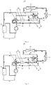
Fig. 1 is a schematic view illustrating a flow direction of a refrigerant in a heat pump system in a first heating mode of the present disclosure. -
Fig. 2 is a schematic view illustrating a flow direction of a refrigerant in a heat pump system in a second heating mode of the present disclosure. -
Fig. 3 is a schematic view illustrating a flow direction of a refrigerant in a heat pump system in a defrosting mode of the present disclosure. -
Fig. 4 is a schematic view illustrating a flow direction of a refrigerant in a heat pump system in a refrigeration mode of the present disclosure. -
Reference numeral Name Reference numeral Name 100 heat pump system D1 fourth valve port 10 compressor assembly 42 second four- way valve 11 compressor A2 fifth valve port 111 exhaust port B2 sixth valve port 112 liquid returning port C2 seventh valve port 12 liquid separator D2 eighth valve port 20 outdoor heat exchanger 43 first solenoid valve 30 indoor heat exchanger 50 heating and heat accumulation device 40 switching device 51 heating assembly 41 first four- way valve 52 heat exchanger A1 first valve port 60 first check valve B1 second valve port 70 throttling device C1 third valve port 80 second check valve - The realization of the object, the function features and the advantages of the present disclosure will be further described in combination with the embodiments with reference to the accompanying drawings.
- Technical solutions in embodiments of the present disclosure will be clearly and completely described below with reference to the accompanying drawings in the embodiments of the present disclosure. Obviously, the embodiments described herein are only a part but not all of the embodiments of the present disclosure. Based on the embodiments of the present disclosure, all other embodiments obtained by those skilled in the art without paying creative efforts, should fall into the protection scope of the present disclosure.
- It should be noted that all directional indications (such as up, down, left, right, front, back, ...) in the embodiments of the present disclosure are only used to explain relative position relationships and motion situations between components in a specific posture (as illustrated in the drawings). If the specific posture changes, the directional indication also changes accordingly.
- In addition, terms such as "first" and "second" are used herein for purposes of description and are not intended to indicate or imply relative importance or significance or to imply the number of indicated technical features. Thus, the feature defined with "first" and "second" may indicate or imply to comprise one or more of this feature. In addition, the technical solutions of the various embodiments may be combined with one another, but must be based on that those skilled in the art can achieve the combination. When the combination of the technical solutions is contradictory or impossible to implement, it should be considered that the combination of the technical solutions does not exist, and is not covered by the protection scope of the present disclosure.
- The present disclosure provides a
heat pump system 100. - As illustrated in
Fig. 1 to Fig. 4 , in embodiments of the present disclosure, theheat pump system 100 includes acompressor assembly 10, anoutdoor heat exchanger 20, anindoor heat exchanger 30, a heating andheat accumulation device 50 and aswitching device 40. Thecompressor assembly 10, the switchingdevice 40, theoutdoor heat exchanger 20 and theindoor heat exchanger 30 are connected in sequence to form a refrigerating circuit. The heating andheat accumulation device 50 and theswitching device 40 are arranged in series. - The
heat pump system 100 has a first heating mode, a second heating mode and a defrosting mode under switching of theswitching device 40. In the first heating mode, the refrigerant discharged from thecompressor assembly 10 enters theindoor heat exchanger 30 and theoutdoor heat exchanger 20 in sequence via passing through thewitching device 40 and the heating andheat accumulation device 50, and flows back to thecompressor assembly 10. In the second heating mode, the refrigerant discharged from thecompressor assembly 10 enters theindoor heat exchanger 30 and theoutdoor heat exchanger 20 in sequence via passing through the switchingdevice 40, and flows back to the compressor assembly. In the defrosting mode, the refrigerant discharged from thecompressor assembly 10 enters theindoor heat exchanger 30 and theoutdoor heat exchanger 20 in sequence via passing through the switchingdevice 40, and the refrigerant flowing out of theoutdoor heat exchanger 20 flows back to thecompressor assembly 10 via passing through the heating andheat accumulation device 50. - Specifically, the
compressor assembly 10 includes acompressor 11 and aliquid separator 12 connected in series, thecompressor assembly 10 has anexhaust port 111 and aliquid returning port 112, theexhaust port 111 is provided to thecompressor 11, theliquid returning port 112 is provided to theliquid separator 12, and theexhaust port 111 of thecompressor 11 is connected with the switchingdevice 40 for discharging a superheated steam with a high temperature and a high pressure. - In the embodiments, the
heat pump system 100 includes the first heating mode, the second heating mode and the defrosting mode under the switching of theswitching device 40. It can be understood that, when theheat pump system 100 is in the first heating mode, the refrigerant is discharged out of theexhaust port 111 of thecompressor 11, passes through the switchingdevice 40 and the heating andheat accumulation device 50, enters theindoor heat exchanger 30 and theoutdoor heat exchanger 20 in sequence, flows back to theliquid separator 12 through theliquid returning port 112, and flows into thecompressor 11 again. In this process, the refrigerant is further heated by the heating andheat accumulation device 50, such that the refrigerant still has a high temperature after releasing heat in theindoor heat exchanger 30, and allows theoutdoor heat exchanger 20 not to be frosted when absorbing heat in theoutdoor heat exchanger 20, thus improving an operating energy efficiency of the wholeheat pump system 100, and increasing a start-up speed. - After being normally started up to operate, the
heat pump system 100 is switched by the switchingdevice 40 to the second heating mode, and the second heating mode is a normal heating mode. When theheat pump system 100 is in the second heating mode, the refrigerant is discharged out of theexhaust port 111 of thecompressor 11, enters theindoor heat exchanger 30 and theoutdoor heat exchanger 20 in sequence via passing through the switchingdevice 40, flows back to theliquid separator 12 through theliquid returning port 112, and flows into thecompressor 11 again. In this process, the refrigerant with the high temperature and the high pressure discharged out of theexhaust port 111 of thecompressor 11 releases heat in theindoor heat exchanger 30, so as to increase a temperature of an indoor environment, and absorbs heat in theoutdoor heat exchanger 20, so as to realize a normal pure heating mode. It can be understood that, after being normally started up to operate, theheat pump system 100 may also be switched between the first heating mode and the second heating mode. - When the
heat pump system 100 defrosts in the defrosting mode, the refrigerant is discharged out of theexhaust port 111 of thecompressor 11, further partially condensed in theindoor heat exchanger 30, and then flows to theoutdoor heat exchanger 20 to defrost theoutdoor heat exchanger 20. The refrigerant flowing out of theoutdoor heat exchanger 20 absorbs heat and evaporates through heating andheat accumulation device 40, further flows back to theliquid separator 12 through theliquid returning port 112, and flows into thecompressor 11 again, so as to realize the defrosting without stopping the heating. Thus, during the defrosting, the indoor temperature keeps not to be decreased, so as to improve the operating energy efficiency and the heating comfort of theheat pump system 100. - The
heat pump system 100 according to embodiments of the present disclosure, the switchingdevice 40 is used to switch different modes of the refrigerant discharged from thecompressor assembly 10, and the heating andheat accumulation device 40 allows theheat pump system 100 to defrost without stopping the heating while heating, thus improving the operating energy efficiency and the heating comfort of the system. - Further, as illustrated in
Fig. 1 to Fig. 3 , in the embodiment, the switchingdevice 40 includes a first four-way valve 41 and a second four-way valve 42 connected in series. The first four-way valve 41 has a first valve port A1, a second valve port B1, a third valve port C1 and a fourth valve port D1. The second four-way valve 42 has a fifth valve port A2, a sixth valve port B2, a seventh valve port C2 and an eighth valve port D2. - Specifically, the
compressor assembly 10 is communicated with the first valve port A1, theoutdoor heat exchanger 20 is communicated with the eighth valve port D2, the heating andheat accumulation device 50 has a first end communicated with the fourth valve port D1 and a second end communicated with the fifth valve port A2, theindoor heat exchanger 30 is communicated with the second valve port B1 and the sixth valve port B2, and the third valve port C1 and the seventh valve port C2 are both communicated with a suction end of thecompressor assembly 10. It can be understood that theheat pump system 100 of the present disclosure can achieve the switch of different modes by switching the valve ports of the first four-way valve 41 and the second four-way valve 42, and also the heating andheat accumulation device 50 is used to cooperate with the different modes, such that theheat pump system 100 can achieve the quick start-up, the normal heating, the defrosting without stopping the heating, and other functions, thus improving the operating energy efficiency and the heating comfort of the system. - In the embodiment, when the
heat pump system 100 is in the first heating mode, the first valve port A1 of the first four-way valve 41 is communicated with the fourth valve port D1 of the first four-way valve 41, and the fifth valve port A2 of the second four-way valve 42 is communicated with the sixth valve port B2, the seventh valve port C2 and the eighth valve port D2 of the second four-way valve 42, respectively. The refrigerant discharged out of theexhaust port 111 of thecompressor 11 passes through the first valve port A1 and the fourth valve port D1 of the first four-way valve 41, then is further heated by the heating andheat accumulation device 50, and enters theindoor heat exchanger 30 to release heat after passing through the fifth valve port A2 and the sixth valve port B2 of the second four-way valve 42. In this case, the refrigerant still has a high temperature, and absorbs heat in theoutdoor heat exchanger 20. Then, the refrigerant flows out of the eighth valve port D2 and the seventh valve port C2 of the second four-way valve 42, further flows back to theliquid separator 12 through theliquid returning port 112, and flows into thecompressor 11 again. Since the refrigerant of the high temperature absorbs heat in theoutdoor heat exchanger 20, theoutdoor heat exchanger 20 will not be frosted, thus improving the operating energy efficiency of the wholeheat pump system 100, and increasing the start-up speed. - When the
heat pump system 100 is in the second heating mode, the first valve port A1 of the first four-way valve 41 is communicated with the second valve port B1 of the first four-way valve 41, and the seventh valve port C2 of the second four-way valve 42 is communicated with the eighth valve port D2 of the second four-way valve 42. The refrigerant discharged out of theexhaust port 111 of thecompressor 11 passes through the first valve port A1 and the second valve port B1 of the first four-way valve 41, enters theindoor heat exchanger 30 to release heat, so as to increase a temperature in an indoor environment, further absorbs heat in theoutdoor heat exchanger 20, then flows out of the eighth valve port D2 and the seventh valve port C2 of the second four-way valve 42, back to theliquid separator 12 through theliquid returning port 112, and further into thecompressor 11 again, thus realizing the normal pure heating mode. - When the
heat pump system 100 is in the defrosting mode, the first valve port A1 of the first four-way valve 41 is communicated with the second valve port B1, the third valve port C1 and the fourth valve port D1 of the first four-way valve 41, and the fifth valve port A2 of the second four-way valve 42 is communicated with the eighth valve port D2 of the second four-way valve 42. The refrigerant discharged out of theexhaust port 111 of thecompressor 11 passes through the first valve port A1 and the second valve port B1 of the first four-way valve 41, enters theindoor heat exchanger 30 to release heat, so as to increase the temperature in the indoor environment, further absorbs heat in theoutdoor heat exchanger 20, then flows out of the eighth valve port D2 and the fifth valve port A2 of the second four-way valve 42, further absorbs heat and evaporates through the heating andheat accumulation device 40, and flows back to theliquid separator 12 through theliquid returning port 112, and further into thecompressor 11 again. In this process, theheat pump system 100 achieves the defrosting without stopping the heating, such that the indoor temperature keeps not to be decreased during the defrosting, thus improving the operating energy efficiency and the heating comfort of theheat pump system 100. - Further, as illustrated in
Fig. 4 , theheat pump system 100 also has a refrigeration mode under the switch of theswitching device 40, i.e. a normal refrigeration mode of theheat pump system 100. When theheat pump system 100 is in the refrigeration mode, the first valve port A1 of the first four-way valve 41 is communicated with the fourth valve port D1 of the first four-way valve 41, and the fifth valve port A2 of the second four-way valve 42 is communicated with the eighth valve port D2, the sixth valve port B2 and the seventh valve port C2 of the second four-way valve 42, respectively. The refrigerant discharged out of theexhaust port 111 of thecompressor 11 passes through the first valve port A1 and the fourth valve port D1 of the first four-way valve 41, and further through the heating andheat accumulation device 40. In this case, the heating andheat accumulation device 40 absorbs and stores a part of heat of the refrigerant with the high temperature and the high pressure. The refrigerant further flows into theoutdoor heat exchanger 20 to release heat through the fifth valve port A2 and the eighth valve port D2 of the second four-way valve 42, also absorbs heat in theindoor heat exchanger 30, so as to reduce the temperature in the indoor environment, and flows out of the sixth valve port B2 and the seventh valve port C2 of the second four-way valve 42, back to theliquid separator 12 through theliquid returning port 112, and into thecompressor 11 again. - Further, as illustrated in
Fig. 1 to Fig. 4 , in the embodiments, the switchingdevice 40 further includes afirst solenoid valve 43, and thefirst solenoid valve 43 is arranged between the sixth valve port B2 and theindoor heat exchanger 30. It can be understood that, by providing thefirst solenoid valve 43, it is convenient for thefirst solenoid valve 43 to cooperate with the second four-way valve 42 when theswitching device 40 switches the different modes, thus realizing the direct switch of the different modes smoothly. - Further, as illustrated in
Fig. 1 to Fig. 4 , in the embodiments, theheat pump system 100 further includes athrottling device 70 and afirst check valve 60, thefirst check valve 60 is connected between theoutdoor heat exchanger 20 and the heating andheat accumulation device 50, the throttlingdevice 70 has a first end communicated with the heating andheat accumulation device 50, and a second end communicated with the fifth valve port A2 and thefirst check valve 60. It can be understood that the throttlingdevice 70 is an electronic expansion valve or an capillary tube. - Further, as illustrated in
Fig. 1 to Fig. 4 , in the embodiments, theheat pump system 100 further includes asecond check valve 80, and thesecond check valve 80 is connected between the second valve port B1 and theindoor heat exchanger 30. - Specifically, when the
heat pump system 100 is in the first heating mode, the throttlingdevice 70 and thefirst solenoid valve 43 are open, thefirst check valve 60 and thesecond check valve 80 are closed, the first valve port A1 and the fourth valve port D1 of the first four-way valve 41 communicates theexhaust port 111 of thecompressor 11 with the heating andheat accumulation device 50, the fifth valve port A2 and the sixth valve port B2 of the second four-way valve 42 communicates the heating andheat accumulation device 50 with thefirst solenoid valve 43 and theindoor heat exchanger 30. The gaseous refrigerant with the high pressure discharged out of theexhaust port 111 of thecompressor 11 is heated in the heating and heat accumulation device 50 (or is condensed to release a part of heat to the heating and heat accumulation device 50), and then is carried to theindoor heat exchanger 30 to release heat through thefirst solenoid valve 43. The liquid refrigerant flowing out of theindoor heat exchanger 30 absorbs heat and evaporates into the gaseous refrigerant in theoutdoor heat exchanger 20, and flows out of the eighth valve port D2 and the seventh valve port C2 of the second four-way valve 42, back to theliquid separator 12 through theliquid returning port 112, and further into thecompressor 11 again. - When the
heat pump system 100 is in the second heating mode, the throttlingdevice 70, thefirst solenoid valve 43 and thefirst check valve 60 are closed, thesecond check valve 80 is open, and the first valve port A1 and the second valve port B1 of the first four-way valve 41 communicate theexhaust port 111 of thecompressor 11 with thesecond check valve 80 and theindoor heat exchanger 30. The gaseous refrigerant with the high pressure discharged out of theexhaust port 111 of thecompressor 11 flows to theindoor heat exchanger 30 to release heat through the first four-way valve 41 and thesecond check valve 80, so as to increase the temperature in the indoor environment. The liquid refrigerant with the high pressure absorbs heat and evaporates into the gaseous refrigerant in theoutdoor heat exchanger 20, and flows out of the eighth valve port D2 and the seventh valve port C2 of the second four-way valve 42, back to theliquid separator 12 through theliquid returning port 112, and into thecompressor 11 again, thus achieving the normal pure heating mode. - When the
heat pump system 100 is in the defrosting mode, the throttlingdevice 70, thefirst check valve 60 and thesecond check valve 80 are open, thefirst solenoid valve 43 is closed, and the first valve port A1 and the second valve port B1 of the first four-way valve 41 communicate theexhaust port 111 of thecompressor 11 with thesecond check valve 80 and theindoor heat exchanger 30. The gaseous refrigerant with the high pressure discharged out of theexhaust port 111 of thecompressor 11 flows to theindoor heat exchanger 30 to release heat through the first four-way valve 41 and thesecond check valve 80, so as to increase the temperature in the indoor environment. The refrigerant continues to be condensed to release heat in theoutdoor heat exchanger 20, so as to allow the frost formed on theoutdoor heat exchanger 20 to thaw. The generated liquid refrigerant passes through thefirst check valve 60 and thethrottling device 70, absorbs heat and evaporates while passing through the heating andheat accumulation device 40, and flows back to theliquid separator 12 through theliquid returning port 112 after passing through the fourth valve port D1 and the third valve port C1 of the first four-way valve 41, and further into thecompressor 11 again, such that theheat pump system 100 achieves the defrosting without stopping the heating. During the defrosting, the indoor temperature keeps not to be decreased, thus improving the operating energy efficiency and the heating comfort of theheat pump system 100. - It can be understood that, in the defrosting mode, the refrigerant flows from the
outdoor heat exchanger 20 to the heating andheat accumulation device 40 via two flow paths. In a first one of the two flow paths, the refrigerant flows from theoutdoor heat exchanger 20 to the heating andheat accumulation device 40 via thefirst check valve 60 and thethrottling device 70. In a second one of the two flow paths, the refrigerant flows from theoutdoor heat exchanger 20 to the heating andheat accumulation device 40 via the eighth valve port D2 and the fifth valve port A2 of the second four-way valve 42, and thethrottling device 70. In this process, due to influences on the two flow paths by the pressure, the refrigerant generally flows to the heating andheat accumulation device 40 in the first path, while the second four-way valve 42 is out of action temporarily. - When the
heat pump system 100 is in the refrigeration mode, the throttlingdevice 70 and thefirst check valve 60 are open, thefirst check valve 60 and thesecond check valve 80 are closed, the first valve port A1 and the fourth valve port D1 of the first four-way valve 41 communicate theexhaust port 111 of thecompressor 11 with the heating andheat accumulation device 50, the fifth valve port A2 and the eighth valve port D2 of the second four-way valve 42 communicate the heating andheat accumulation device 50 with theoutdoor heat exchanger 20, and the sixth valve port B2 and the seventh valve port C2 of the second four-way valve 42 communicate theindoor heat exchanger 30 with theliquid returning port 112 of theliquid separator 12. The gaseous refrigerant with the high pressure discharged out of theexhaust port 111 of thecompressor 11 passes through the first four-way valve 41, the throttlingdevice 70 and the second four-way valve 42, then flows into theoutdoor heat exchanger 20 to be condensed into the liquid refrigerant with the high pressure, further flows into theindoor heat exchanger 30 to be throttled and evaporated into the gaseous refrigerant with the low pressure, and flows out of the sixth valve port B2 and the seventh valve port C2 of the second four-way valve 42, back to theliquid separator 12 through theliquid returning port 112, and into thecompressor 11 again, thus reducing the temperature in the indoor environment. - Further, as illustrated in
Fig. 1 to Fig. 4 , in an embodiment, the heating andheat accumulation device 50 includes a second solenoid valve, aheat exchanger 52 and aheating assembly 51, theheating assembly 51 is arranged to an outer wall of theheat exchanger 52, and theheat exchanger 52 is connected in series with the second solenoid valve and communicated with the switchingdevice 40. It can be understood that the second solenoid valve is configured to control operations states of the heat exchanger and theheating assembly 51. Theheating assembly 51 may be an exogenous heater, and the exogenous heater may be an electric heating member or a gas heating member. - In the embodiments, the
heating assembly 51 is preferably configured as the electric heating member, and the electric heating member is attached to the outer wall of theheat exchanger 52. The electric heating member is controlled by the second solenoid valve, so as to heat the outer wall of theheat exchanger 52, such that the refrigerant can achieve a heat exchange by theheat exchanger 52 when passing through theheat exchanger 52. - In another embodiment, the heating and
heat accumulation device 50 includes a second solenoid valve, aheat exchanger 52 and a heat accumulation assembly (not illustrated), the heat accumulation assembly may be arranged to an outer wall of theheat exchanger 52, and theheat exchanger 52 is connected in series with the second solenoid valve and communicated with the switchingdevice 40. It can be understood that the second solenoid valve is configured to control an operation state of the heat exchanger, and the heat accumulation assembly may be a heat accumulator. The heat accumulator may use heat accumulation materials for heat exchange. Preferably, the accumulation materials may be phase-change materials or sensible heat and heat accumulation materials, which is not limited herein. The heat accumulation assembly preferably uses a heat accumulation sheet made of the heat accumulation materials, and the heat accumulation sheet is arranged to the outer wall of theheat exchanger 52. When the refrigerant with the high temperature has the heat exchange by theheat exchanger 52, the heat accumulation sheet accumulates heat by theheat exchanger 52. The heat accumulated in the heat accumulation sheet is used to evaporate the liquid refrigerant with the low temperature when the liquid refrigerant with the low temperature returns to the compressor, so as to reduce the refrigerant content in the refrigeration oil returned from theliquid separator 12, and hence to increase the refrigeration oil content in the compressor to a safe concentration, thereby achieving a normal operation. Thus, the time from the start-up to the high-frequency operation of the compressor is reduced, and the start-up speed of the system is increased. - In a third embodiment, as illustrated in
Fig. 1 to Fig. 4 , the heating andheat accumulation device 50 includes a second solenoid valve, aheat exchanger 52, aheating assembly 51 and a heat accumulation assembly (not illustrated), theheating assembly 51 and the heat accumulation assembly are arranged to an outer wall of theheat exchanger 52 and spaced apart from each other, and theheat exchanger 52 is connected in series with the second solenoid valve and communicated with the switchingdevice 40. - Specifically, the second solenoid valve is configured to control operation states of the heat exchanger and the
heating assembly 51. Theheating assembly 51 may be an exogenous heater, and the exogenous heater may be an electric heating member or a gas heating member. The heat accumulation assembly may be a heat accumulator. The heat accumulator may use heat accumulation materials for heat exchange. Preferably, the accumulation materials may be phase-change materials or sensible heat and heat accumulation materials, which is not limited herein. In the embodiment, theheating assembly 51 is preferably configured as the electric heating member, and the electric heating member is attached to the outer wall of theheat exchanger 52. The electric heating member is controlled by the second solenoid valve, so as to heat the outer wall of theheat exchanger 52, such that the refrigerant can achieve a heat exchange by theheat exchanger 52 when passing through theheat exchanger 52. The heat accumulation assembly preferably uses a heat accumulation sheet made of the heat accumulation materials, and the heat accumulation sheet is arranged to the outer wall of theheat exchanger 52. When theheating assembly 51 heats the outer wall of theheat exchanger 52, and the refrigerant has the heat exchange while passing through theheat exchanger 52, the heat accumulation sheet also accumulates heat by theheat exchanger 52. Or, when the refrigerant with the high temperature has the heat exchange by theheat exchanger 52, the heat accumulation sheet also accumulates heat by theheat exchanger 52. The heat accumulated in the heat accumulation sheet is used to evaporate the liquid refrigerant with the low temperature when the liquid refrigerant with the low temperature returns to the compressor, so as to reduce the refrigerant content in the refrigeration oil returned from theliquid separator 12, and hence to increase the refrigeration oil content in the compressor to a safe concentration, thereby achieving a normal operation. Thus, the time from the start-up to the high-frequency operation of the compressor is reduced, and the start-up speed of the system is increased. - The present disclosure also provides an air conditioner, and the air conditioner includes a
heat pump system 100. Specific structures of the heat pump system can refer to the above embodiments. Since a control method for the heat pump system uses all the technical solutions of all the above embodiments, the control method for the heat pump system at least has all the significant effects resulted from the technical solutions of the above embodiments, which thus will not be repeated herein. - The air conditioner of the present disclosure includes the
heat pump system 100. Theheat pump system 100 uses theswitching device 40 to switch the different modes of the refrigerant discharged from thecompressor assembly 10, and also uses the heating andheat accumulation device 50 to cooperate with the switchingdevice 40, such that theheat pump system 100 can achieve the defrosting without stopping the heating while heating, thus improving the operating energy efficiency and the heating comfort of the air conditioner. - The above descriptions are only preferred embodiments of the present disclosure, and are not intended to limit the protection scope of the present disclosure. Under the concept of the present disclosure, any equivalent structure transformations obtained by using the descriptions and the drawings of the present disclosure, or any direct/indirect usages of the present disclosure in other related technical fields should be fallen within the protection scope of the present disclosure.
Claims (10)
- A heat pump system, comprising a compressor assembly, an outdoor heat exchanger and an indoor heat exchanger, wherein the heat pump system further comprises a heating and heat accumulation device and a switching device, the compressor assembly, the switching device, the outdoor heat exchanger and the indoor heat exchanger are connected in sequence to form a refrigerating circuit, and the heating and heat accumulation device is connected in series with the switching device,
wherein the heat pump system has a first heating mode, a second heating mode and a defrosting mode under the switch of the switching device; in the first heating mode, a refrigerant discharged out of the compressor assembly enters the indoor heat exchanger and the outdoor heat exchanger in sequence after passing through the switching device and the heating and heat accumulation device, and flows back to the compressor assembly; in the second heating mode, the refrigerant discharged out of the compressor assembly enters the indoor heat exchanger and the outdoor heat exchanger in sequence after passing through the switching device, and flows back to the compressor assembly; in the defrosting mode, the refrigerant discharged out of the compressor assembly enters the indoor heat exchanger and the outdoor heat exchanger in sequence after passing through the switching device, and the refrigerant flowing out of the outdoor heat exchanger flows back to the compressor assembly after passing through the heating and heat accumulation device. - The heat pump system according to claim 1, wherein the switching device comprises a first four-way valve and a second four-way valve connected in series, the first four-way valve comprises first to fourth valve ports, the second four-way valve comprises fifth to eighth valve ports, the compressor assembly is communicated with the first valve port, the outdoor heat exchanger is communicated with the eighth valve port, the heating and heat accumulation device has a first end communicated with the fourth valve port and a second end communicated with the fifth valve port, the indoor heat exchanger is communicated with the second valve port and the sixth valve port, the third valve port and the seventh valve port are both communicated with a suction end of the compressor assembly;
in the first heating mode, the first valve port of the first four-way valve is communicated with the fourth valve port of the first four-way valve, and the fifth valve port of the second four-way valve is communicated with the sixth valve port, the seventh valve port is communicated with the eighth valve port of the second four-way valve, respectively;
in the second heating mode, the first valve port of the first four-way valve is communicated with the second valve port of the first four-way valve, and the seventh valve port of the second four-way valve is communicated with the eighth valve port of the second four-way valve;
in the defrosting mode, the first valve port of the first four-way valve is communicated with the second valve port, the third valve port is communicated with the fourth valve port of the first four-way valve, respectively, and the fifth valve port of the second four-way valve is communicated with the eighth valve port of the second four-way valve. - The heat pump system according to claim 2, wherein the switching device further comprises a first solenoid valve, and the first solenoid valve is arranged between the sixth valve port and the indoor heat exchanger.
- The heat pump system according to claim 3, wherein the heat pump system further comprises a first check valve, and the first check valve is connected between the outdoor heat exchanger and the heating and heat accumulation device.
- The heat pump system according to claim 4, wherein the heat pump system further comprises a throttling device, and the throttling device has a first end communicated with the heating and heat accumulation device and a second end communicated with the fifth valve port and the first check valve.
- The heat pump system according to any one of claims 2 to 5, wherein the heat pump system further comprises a second check valve, and the second check valve is connected between the second valve port and the indoor heat exchanger.
- The heat pump system according to claim 6, wherein the heat pump system further has a refrigeration mode by switching the switching device, and in the refrigeration mode, the first valve port of the first four-way valve is communicated with the fourth valve port of the first four-way valve, the fifth valve port of the second four-way valve is communicated with the eighth valve port, the sixth valve port is communicated with the seventh valve port of the second four-way valve, respectively.
- The heat pump system according to claim 1, wherein the heating and heat accumulation device comprises a second solenoid valve and a heat exchanger, and the heat exchanger is connected in series with the second solenoid valve and communicated with the switching device;
the heating and heat accumulation device further comprises a heating assembly and/or a heat accumulation assembly arranged on an outer wall of the heat exchanger. - The heat pump system according to claim 8, wherein the heating assembly is configured as an exogenous heater; and/or
the heat accumulation assembly is configured as a heat accumulator. - An air conditioner, comprising a heat pump system according to any one of claims 1 to 9.
Applications Claiming Priority (2)
| Application Number | Priority Date | Filing Date | Title |
|---|---|---|---|
| CN201811253993.8A CN109405335B (en) | 2018-10-24 | 2018-10-24 | Heat pump system and air conditioner |
| PCT/CN2019/089266 WO2020082735A1 (en) | 2018-10-24 | 2019-05-30 | Heat pump system and air conditioner |
Publications (3)
| Publication Number | Publication Date |
|---|---|
| EP3680578A1 true EP3680578A1 (en) | 2020-07-15 |
| EP3680578A4 EP3680578A4 (en) | 2020-08-05 |
| EP3680578B1 EP3680578B1 (en) | 2022-12-28 |
Family
ID=65469801
Family Applications (1)
| Application Number | Title | Priority Date | Filing Date |
|---|---|---|---|
| EP19801655.2A Active EP3680578B1 (en) | 2018-10-24 | 2019-05-30 | Heat pump system and air conditioner |
Country Status (4)
| Country | Link |
|---|---|
| US (1) | US20210364206A1 (en) |
| EP (1) | EP3680578B1 (en) |
| CN (1) | CN109405335B (en) |
| WO (1) | WO2020082735A1 (en) |
Families Citing this family (7)
| Publication number | Priority date | Publication date | Assignee | Title |
|---|---|---|---|---|
| CN109405335B (en) * | 2018-10-24 | 2020-05-22 | 广东美的暖通设备有限公司 | Heat pump system and air conditioner |
| CN111780465A (en) * | 2020-06-22 | 2020-10-16 | 上海爱斯达克汽车空调系统有限公司 | Shutdown-free electric automobile heat pump defrosting system and operation method thereof |
| CN115076966B (en) | 2021-03-15 | 2024-06-18 | 广东美的暖通设备有限公司 | Air conditioner control method and device |
| CN113587469B (en) * | 2021-08-02 | 2022-11-15 | 珠海格力节能环保制冷技术研究中心有限公司 | Control device and method of temperature control system and temperature control system |
| CN114110846B (en) * | 2021-11-23 | 2023-05-02 | 珠海格力电器股份有限公司 | Energy storage heat pump system and control method thereof |
| US20240401847A1 (en) * | 2023-06-05 | 2024-12-05 | Rheem Manufacturing Company | Systems and methods for increasing the heating capacity of a heat pump system using at least two reversible valves |
| CN119222825B (en) * | 2023-06-30 | 2025-11-28 | 美的集团股份有限公司 | Control method for heat pump system, and storage medium |
Family Cites Families (8)
| Publication number | Priority date | Publication date | Assignee | Title |
|---|---|---|---|---|
| JPS63116073A (en) * | 1986-10-31 | 1988-05-20 | 株式会社東芝 | Heat accumulation type heat pump |
| KR101436637B1 (en) * | 2008-01-21 | 2014-09-01 | 엘지전자 주식회사 | Air-conditioning system and control method thereof |
| JP2009287903A (en) * | 2008-06-02 | 2009-12-10 | Kansai Electric Power Co Inc:The | Thermal storage type heat pump device |
| CN103791569B (en) * | 2012-10-30 | 2016-10-05 | 珠海格力电器股份有限公司 | Heat pump type air conditioning system |
| CN203964489U (en) * | 2014-07-01 | 2014-11-26 | 珠海格力电器股份有限公司 | Air conditioner heat pump system |
| CN105865073B (en) * | 2016-04-18 | 2018-06-01 | 广东美的制冷设备有限公司 | Air-conditioning system and its control method |
| CN108224840B (en) * | 2018-01-25 | 2023-08-15 | 珠海格力电器股份有限公司 | Heat pump air conditioning system and control method |
| CN109405335B (en) * | 2018-10-24 | 2020-05-22 | 广东美的暖通设备有限公司 | Heat pump system and air conditioner |
-
2018
- 2018-10-24 CN CN201811253993.8A patent/CN109405335B/en active Active
-
2019
- 2019-05-30 US US16/618,158 patent/US20210364206A1/en not_active Abandoned
- 2019-05-30 EP EP19801655.2A patent/EP3680578B1/en active Active
- 2019-05-30 WO PCT/CN2019/089266 patent/WO2020082735A1/en not_active Ceased
Also Published As
| Publication number | Publication date |
|---|---|
| WO2020082735A1 (en) | 2020-04-30 |
| EP3680578B1 (en) | 2022-12-28 |
| CN109405335B (en) | 2020-05-22 |
| CN109405335A (en) | 2019-03-01 |
| EP3680578A4 (en) | 2020-08-05 |
| US20210364206A1 (en) | 2021-11-25 |
Similar Documents
| Publication | Publication Date | Title |
|---|---|---|
| EP3680578B1 (en) | Heat pump system and air conditioner | |
| CN211739591U (en) | Air conditioning system and air conditioning equipment that incessant heats | |
| JP2003075009A (en) | Heat pump system | |
| CN104515318B (en) | Air conditioning system | |
| EP4012276B1 (en) | Air conditioner and control method therefor | |
| KR20150134676A (en) | Heat pump | |
| EP2995883A2 (en) | Refrigerating cycle apparatus | |
| CN109398027A (en) | The board-like automobile-used heat pump air conditioning system of direct-type global function | |
| CN112268381A (en) | Heat pump system, control method and control device thereof, air conditioning equipment and storage medium | |
| CN115751466B (en) | Air conditioning system | |
| CN110425765B (en) | Heat exchange system and control method | |
| CN112228992A (en) | Heat pump system, control method and control device thereof, air conditioning equipment and storage medium | |
| KR102082881B1 (en) | Multi-air conditioner for heating and cooling operations at the same time | |
| CN112728800A (en) | Air conditioner | |
| CN203550270U (en) | Air conditioning system | |
| CN210832607U (en) | Air conditioner | |
| CN203550269U (en) | Air conditioning system | |
| JP4023387B2 (en) | Refrigeration equipment | |
| CN218296285U (en) | Heat pump system, water heater and air conditioner | |
| KR101979577B1 (en) | Heat pump system | |
| CN219160502U (en) | Air conditioner | |
| JPH02258467A (en) | Vehicle heat pump air conditioner | |
| CN118856447B (en) | Air conditioning system and control method thereof | |
| CN214501455U (en) | Air conditioner | |
| CN108592440A (en) | A kind of Efficient track heat pump air conditioning system and its Defrost method |
Legal Events
| Date | Code | Title | Description |
|---|---|---|---|
| STAA | Information on the status of an ep patent application or granted ep patent |
Free format text: STATUS: UNKNOWN |
|
| STAA | Information on the status of an ep patent application or granted ep patent |
Free format text: STATUS: THE INTERNATIONAL PUBLICATION HAS BEEN MADE |
|
| PUAI | Public reference made under article 153(3) epc to a published international application that has entered the european phase |
Free format text: ORIGINAL CODE: 0009012 |
|
| STAA | Information on the status of an ep patent application or granted ep patent |
Free format text: STATUS: REQUEST FOR EXAMINATION WAS MADE |
|
| 17P | Request for examination filed |
Effective date: 20191121 |
|
| AK | Designated contracting states |
Kind code of ref document: A1 Designated state(s): AL AT BE BG CH CY CZ DE DK EE ES FI FR GB GR HR HU IE IS IT LI LT LU LV MC MK MT NL NO PL PT RO RS SE SI SK SM TR |
|
| AX | Request for extension of the european patent |
Extension state: BA ME |
|
| A4 | Supplementary search report drawn up and despatched |
Effective date: 20200708 |
|
| RIC1 | Information provided on ipc code assigned before grant |
Ipc: F25B 41/04 20060101ALI20200702BHEP Ipc: F25B 47/02 20060101ALI20200702BHEP Ipc: F25B 13/00 20060101AFI20200702BHEP |
|
| RIN1 | Information on inventor provided before grant (corrected) |
Inventor name: TAN, ZHIJUN Inventor name: LUO, BIN Inventor name: ZHAN, LEI Inventor name: LIU, SHUQING Inventor name: YANG, KUN |
|
| DAV | Request for validation of the european patent (deleted) | ||
| DAX | Request for extension of the european patent (deleted) | ||
| STAA | Information on the status of an ep patent application or granted ep patent |
Free format text: STATUS: EXAMINATION IS IN PROGRESS |
|
| 17Q | First examination report despatched |
Effective date: 20220310 |
|
| GRAP | Despatch of communication of intention to grant a patent |
Free format text: ORIGINAL CODE: EPIDOSNIGR1 |
|
| STAA | Information on the status of an ep patent application or granted ep patent |
Free format text: STATUS: GRANT OF PATENT IS INTENDED |
|
| RIC1 | Information provided on ipc code assigned before grant |
Ipc: F25B 41/20 20210101ALI20220921BHEP Ipc: F25B 47/02 20060101ALI20220921BHEP Ipc: F25B 13/00 20060101AFI20220921BHEP |
|
| INTG | Intention to grant announced |
Effective date: 20221012 |
|
| GRAS | Grant fee paid |
Free format text: ORIGINAL CODE: EPIDOSNIGR3 |
|
| GRAA | (expected) grant |
Free format text: ORIGINAL CODE: 0009210 |
|
| STAA | Information on the status of an ep patent application or granted ep patent |
Free format text: STATUS: THE PATENT HAS BEEN GRANTED |
|
| AK | Designated contracting states |
Kind code of ref document: B1 Designated state(s): AL AT BE BG CH CY CZ DE DK EE ES FI FR GB GR HR HU IE IS IT LI LT LU LV MC MK MT NL NO PL PT RO RS SE SI SK SM TR |
|
| REG | Reference to a national code |
Ref country code: GB Ref legal event code: FG4D |
|
| REG | Reference to a national code |
Ref country code: CH Ref legal event code: EP |
|
| REG | Reference to a national code |
Ref country code: DE Ref legal event code: R096 Ref document number: 602019023746 Country of ref document: DE |
|
| REG | Reference to a national code |
Ref country code: AT Ref legal event code: REF Ref document number: 1540749 Country of ref document: AT Kind code of ref document: T Effective date: 20230115 |
|
| REG | Reference to a national code |
Ref country code: IE Ref legal event code: FG4D |
|
| REG | Reference to a national code |
Ref country code: LT Ref legal event code: MG9D |
|
| PG25 | Lapsed in a contracting state [announced via postgrant information from national office to epo] |
Ref country code: SE Free format text: LAPSE BECAUSE OF FAILURE TO SUBMIT A TRANSLATION OF THE DESCRIPTION OR TO PAY THE FEE WITHIN THE PRESCRIBED TIME-LIMIT Effective date: 20221228 Ref country code: NO Free format text: LAPSE BECAUSE OF FAILURE TO SUBMIT A TRANSLATION OF THE DESCRIPTION OR TO PAY THE FEE WITHIN THE PRESCRIBED TIME-LIMIT Effective date: 20230328 Ref country code: LT Free format text: LAPSE BECAUSE OF FAILURE TO SUBMIT A TRANSLATION OF THE DESCRIPTION OR TO PAY THE FEE WITHIN THE PRESCRIBED TIME-LIMIT Effective date: 20221228 Ref country code: FI Free format text: LAPSE BECAUSE OF FAILURE TO SUBMIT A TRANSLATION OF THE DESCRIPTION OR TO PAY THE FEE WITHIN THE PRESCRIBED TIME-LIMIT Effective date: 20221228 |
|
| REG | Reference to a national code |
Ref country code: NL Ref legal event code: MP Effective date: 20221228 |
|
| REG | Reference to a national code |
Ref country code: AT Ref legal event code: MK05 Ref document number: 1540749 Country of ref document: AT Kind code of ref document: T Effective date: 20221228 |
|
| PG25 | Lapsed in a contracting state [announced via postgrant information from national office to epo] |
Ref country code: RS Free format text: LAPSE BECAUSE OF FAILURE TO SUBMIT A TRANSLATION OF THE DESCRIPTION OR TO PAY THE FEE WITHIN THE PRESCRIBED TIME-LIMIT Effective date: 20221228 Ref country code: LV Free format text: LAPSE BECAUSE OF FAILURE TO SUBMIT A TRANSLATION OF THE DESCRIPTION OR TO PAY THE FEE WITHIN THE PRESCRIBED TIME-LIMIT Effective date: 20221228 Ref country code: HR Free format text: LAPSE BECAUSE OF FAILURE TO SUBMIT A TRANSLATION OF THE DESCRIPTION OR TO PAY THE FEE WITHIN THE PRESCRIBED TIME-LIMIT Effective date: 20221228 Ref country code: GR Free format text: LAPSE BECAUSE OF FAILURE TO SUBMIT A TRANSLATION OF THE DESCRIPTION OR TO PAY THE FEE WITHIN THE PRESCRIBED TIME-LIMIT Effective date: 20230329 |
|
| PG25 | Lapsed in a contracting state [announced via postgrant information from national office to epo] |
Ref country code: NL Free format text: LAPSE BECAUSE OF FAILURE TO SUBMIT A TRANSLATION OF THE DESCRIPTION OR TO PAY THE FEE WITHIN THE PRESCRIBED TIME-LIMIT Effective date: 20221228 |
|
| P01 | Opt-out of the competence of the unified patent court (upc) registered |
Effective date: 20230526 |
|
| PG25 | Lapsed in a contracting state [announced via postgrant information from national office to epo] |
Ref country code: SM Free format text: LAPSE BECAUSE OF FAILURE TO SUBMIT A TRANSLATION OF THE DESCRIPTION OR TO PAY THE FEE WITHIN THE PRESCRIBED TIME-LIMIT Effective date: 20221228 Ref country code: RO Free format text: LAPSE BECAUSE OF FAILURE TO SUBMIT A TRANSLATION OF THE DESCRIPTION OR TO PAY THE FEE WITHIN THE PRESCRIBED TIME-LIMIT Effective date: 20221228 Ref country code: PT Free format text: LAPSE BECAUSE OF FAILURE TO SUBMIT A TRANSLATION OF THE DESCRIPTION OR TO PAY THE FEE WITHIN THE PRESCRIBED TIME-LIMIT Effective date: 20230428 Ref country code: ES Free format text: LAPSE BECAUSE OF FAILURE TO SUBMIT A TRANSLATION OF THE DESCRIPTION OR TO PAY THE FEE WITHIN THE PRESCRIBED TIME-LIMIT Effective date: 20221228 Ref country code: EE Free format text: LAPSE BECAUSE OF FAILURE TO SUBMIT A TRANSLATION OF THE DESCRIPTION OR TO PAY THE FEE WITHIN THE PRESCRIBED TIME-LIMIT Effective date: 20221228 Ref country code: CZ Free format text: LAPSE BECAUSE OF FAILURE TO SUBMIT A TRANSLATION OF THE DESCRIPTION OR TO PAY THE FEE WITHIN THE PRESCRIBED TIME-LIMIT Effective date: 20221228 Ref country code: AT Free format text: LAPSE BECAUSE OF FAILURE TO SUBMIT A TRANSLATION OF THE DESCRIPTION OR TO PAY THE FEE WITHIN THE PRESCRIBED TIME-LIMIT Effective date: 20221228 |
|
| PG25 | Lapsed in a contracting state [announced via postgrant information from national office to epo] |
Ref country code: SK Free format text: LAPSE BECAUSE OF FAILURE TO SUBMIT A TRANSLATION OF THE DESCRIPTION OR TO PAY THE FEE WITHIN THE PRESCRIBED TIME-LIMIT Effective date: 20221228 Ref country code: PL Free format text: LAPSE BECAUSE OF FAILURE TO SUBMIT A TRANSLATION OF THE DESCRIPTION OR TO PAY THE FEE WITHIN THE PRESCRIBED TIME-LIMIT Effective date: 20221228 Ref country code: IS Free format text: LAPSE BECAUSE OF FAILURE TO SUBMIT A TRANSLATION OF THE DESCRIPTION OR TO PAY THE FEE WITHIN THE PRESCRIBED TIME-LIMIT Effective date: 20230428 Ref country code: AL Free format text: LAPSE BECAUSE OF FAILURE TO SUBMIT A TRANSLATION OF THE DESCRIPTION OR TO PAY THE FEE WITHIN THE PRESCRIBED TIME-LIMIT Effective date: 20221228 |
|
| REG | Reference to a national code |
Ref country code: DE Ref legal event code: R097 Ref document number: 602019023746 Country of ref document: DE |
|
| PG25 | Lapsed in a contracting state [announced via postgrant information from national office to epo] |
Ref country code: DK Free format text: LAPSE BECAUSE OF FAILURE TO SUBMIT A TRANSLATION OF THE DESCRIPTION OR TO PAY THE FEE WITHIN THE PRESCRIBED TIME-LIMIT Effective date: 20221228 |
|
| PLBE | No opposition filed within time limit |
Free format text: ORIGINAL CODE: 0009261 |
|
| STAA | Information on the status of an ep patent application or granted ep patent |
Free format text: STATUS: NO OPPOSITION FILED WITHIN TIME LIMIT |
|
| 26N | No opposition filed |
Effective date: 20230929 |
|
| REG | Reference to a national code |
Ref country code: CH Ref legal event code: PL |
|
| PG25 | Lapsed in a contracting state [announced via postgrant information from national office to epo] |
Ref country code: MC Free format text: LAPSE BECAUSE OF FAILURE TO SUBMIT A TRANSLATION OF THE DESCRIPTION OR TO PAY THE FEE WITHIN THE PRESCRIBED TIME-LIMIT Effective date: 20221228 |
|
| REG | Reference to a national code |
Ref country code: BE Ref legal event code: MM Effective date: 20230531 |
|
| PG25 | Lapsed in a contracting state [announced via postgrant information from national office to epo] |
Ref country code: SI Free format text: LAPSE BECAUSE OF FAILURE TO SUBMIT A TRANSLATION OF THE DESCRIPTION OR TO PAY THE FEE WITHIN THE PRESCRIBED TIME-LIMIT Effective date: 20221228 Ref country code: MC Free format text: LAPSE BECAUSE OF FAILURE TO SUBMIT A TRANSLATION OF THE DESCRIPTION OR TO PAY THE FEE WITHIN THE PRESCRIBED TIME-LIMIT Effective date: 20221228 Ref country code: LU Free format text: LAPSE BECAUSE OF NON-PAYMENT OF DUE FEES Effective date: 20230530 Ref country code: LI Free format text: LAPSE BECAUSE OF NON-PAYMENT OF DUE FEES Effective date: 20230531 Ref country code: CH Free format text: LAPSE BECAUSE OF NON-PAYMENT OF DUE FEES Effective date: 20230531 |
|
| REG | Reference to a national code |
Ref country code: IE Ref legal event code: MM4A |
|
| PG25 | Lapsed in a contracting state [announced via postgrant information from national office to epo] |
Ref country code: IE Free format text: LAPSE BECAUSE OF NON-PAYMENT OF DUE FEES Effective date: 20230530 |
|
| PG25 | Lapsed in a contracting state [announced via postgrant information from national office to epo] |
Ref country code: IE Free format text: LAPSE BECAUSE OF NON-PAYMENT OF DUE FEES Effective date: 20230530 |
|
| PG25 | Lapsed in a contracting state [announced via postgrant information from national office to epo] |
Ref country code: BE Free format text: LAPSE BECAUSE OF NON-PAYMENT OF DUE FEES Effective date: 20230531 |
|
| PG25 | Lapsed in a contracting state [announced via postgrant information from national office to epo] |
Ref country code: BG Free format text: LAPSE BECAUSE OF FAILURE TO SUBMIT A TRANSLATION OF THE DESCRIPTION OR TO PAY THE FEE WITHIN THE PRESCRIBED TIME-LIMIT Effective date: 20221228 |
|
| PG25 | Lapsed in a contracting state [announced via postgrant information from national office to epo] |
Ref country code: BG Free format text: LAPSE BECAUSE OF FAILURE TO SUBMIT A TRANSLATION OF THE DESCRIPTION OR TO PAY THE FEE WITHIN THE PRESCRIBED TIME-LIMIT Effective date: 20221228 |
|
| PGFP | Annual fee paid to national office [announced via postgrant information from national office to epo] |
Ref country code: DE Payment date: 20250516 Year of fee payment: 7 |
|
| PGFP | Annual fee paid to national office [announced via postgrant information from national office to epo] |
Ref country code: GB Payment date: 20250519 Year of fee payment: 7 |
|
| PGFP | Annual fee paid to national office [announced via postgrant information from national office to epo] |
Ref country code: IT Payment date: 20250519 Year of fee payment: 7 |
|
| PGFP | Annual fee paid to national office [announced via postgrant information from national office to epo] |
Ref country code: FR Payment date: 20250519 Year of fee payment: 7 |
|
| PG25 | Lapsed in a contracting state [announced via postgrant information from national office to epo] |
Ref country code: CY Free format text: LAPSE BECAUSE OF FAILURE TO SUBMIT A TRANSLATION OF THE DESCRIPTION OR TO PAY THE FEE WITHIN THE PRESCRIBED TIME-LIMIT; INVALID AB INITIO Effective date: 20190530 |
|
| PG25 | Lapsed in a contracting state [announced via postgrant information from national office to epo] |
Ref country code: HU Free format text: LAPSE BECAUSE OF FAILURE TO SUBMIT A TRANSLATION OF THE DESCRIPTION OR TO PAY THE FEE WITHIN THE PRESCRIBED TIME-LIMIT; INVALID AB INITIO Effective date: 20190530 |
|
| PG25 | Lapsed in a contracting state [announced via postgrant information from national office to epo] |
Ref country code: TR Free format text: LAPSE BECAUSE OF FAILURE TO SUBMIT A TRANSLATION OF THE DESCRIPTION OR TO PAY THE FEE WITHIN THE PRESCRIBED TIME-LIMIT Effective date: 20221228 |