EP3680554A1 - Cooking appliance - Google Patents
Cooking appliance Download PDFInfo
- Publication number
- EP3680554A1 EP3680554A1 EP19215447.4A EP19215447A EP3680554A1 EP 3680554 A1 EP3680554 A1 EP 3680554A1 EP 19215447 A EP19215447 A EP 19215447A EP 3680554 A1 EP3680554 A1 EP 3680554A1
- Authority
- EP
- European Patent Office
- Prior art keywords
- layer
- cooking appliance
- component
- silver nanowires
- insulation film
- Prior art date
- Legal status (The legal status is an assumption and is not a legal conclusion. Google has not performed a legal analysis and makes no representation as to the accuracy of the status listed.)
- Granted
Links
Images



Classifications
-
- F—MECHANICAL ENGINEERING; LIGHTING; HEATING; WEAPONS; BLASTING
- F24—HEATING; RANGES; VENTILATING
- F24C—DOMESTIC STOVES OR RANGES ; DETAILS OF DOMESTIC STOVES OR RANGES, OF GENERAL APPLICATION
- F24C15/00—Details
- F24C15/02—Doors specially adapted for stoves or ranges
- F24C15/04—Doors specially adapted for stoves or ranges with transparent panels
-
- F—MECHANICAL ENGINEERING; LIGHTING; HEATING; WEAPONS; BLASTING
- F24—HEATING; RANGES; VENTILATING
- F24C—DOMESTIC STOVES OR RANGES ; DETAILS OF DOMESTIC STOVES OR RANGES, OF GENERAL APPLICATION
- F24C15/00—Details
-
- A—HUMAN NECESSITIES
- A47—FURNITURE; DOMESTIC ARTICLES OR APPLIANCES; COFFEE MILLS; SPICE MILLS; SUCTION CLEANERS IN GENERAL
- A47J—KITCHEN EQUIPMENT; COFFEE MILLS; SPICE MILLS; APPARATUS FOR MAKING BEVERAGES
- A47J37/00—Baking; Roasting; Grilling; Frying
- A47J37/06—Roasters; Grills; Sandwich grills
- A47J37/0623—Small-size cooking ovens, i.e. defining an at least partially closed cooking cavity
- A47J37/0664—Accessories
-
- A—HUMAN NECESSITIES
- A47—FURNITURE; DOMESTIC ARTICLES OR APPLIANCES; COFFEE MILLS; SPICE MILLS; SUCTION CLEANERS IN GENERAL
- A47J—KITCHEN EQUIPMENT; COFFEE MILLS; SPICE MILLS; APPARATUS FOR MAKING BEVERAGES
- A47J27/00—Cooking-vessels
- A47J27/04—Cooking-vessels for cooking food in steam; Devices for extracting fruit juice by means of steam ; Vacuum cooking vessels
-
- A—HUMAN NECESSITIES
- A47—FURNITURE; DOMESTIC ARTICLES OR APPLIANCES; COFFEE MILLS; SPICE MILLS; SUCTION CLEANERS IN GENERAL
- A47J—KITCHEN EQUIPMENT; COFFEE MILLS; SPICE MILLS; APPARATUS FOR MAKING BEVERAGES
- A47J37/00—Baking; Roasting; Grilling; Frying
- A47J37/06—Roasters; Grills; Sandwich grills
- A47J37/0623—Small-size cooking ovens, i.e. defining an at least partially closed cooking cavity
- A47J37/0629—Small-size cooking ovens, i.e. defining an at least partially closed cooking cavity with electric heating elements
- A47J37/0641—Small-size cooking ovens, i.e. defining an at least partially closed cooking cavity with electric heating elements with forced air circulation, e.g. air fryers
-
- B—PERFORMING OPERATIONS; TRANSPORTING
- B32—LAYERED PRODUCTS
- B32B—LAYERED PRODUCTS, i.e. PRODUCTS BUILT-UP OF STRATA OF FLAT OR NON-FLAT, e.g. CELLULAR OR HONEYCOMB, FORM
- B32B15/00—Layered products comprising a layer of metal
- B32B15/02—Layer formed of wires, e.g. mesh
-
- B—PERFORMING OPERATIONS; TRANSPORTING
- B32—LAYERED PRODUCTS
- B32B—LAYERED PRODUCTS, i.e. PRODUCTS BUILT-UP OF STRATA OF FLAT OR NON-FLAT, e.g. CELLULAR OR HONEYCOMB, FORM
- B32B15/00—Layered products comprising a layer of metal
- B32B15/04—Layered products comprising a layer of metal comprising metal as the main or only constituent of a layer, which is next to another layer of the same or of a different material
-
- B—PERFORMING OPERATIONS; TRANSPORTING
- B32—LAYERED PRODUCTS
- B32B—LAYERED PRODUCTS, i.e. PRODUCTS BUILT-UP OF STRATA OF FLAT OR NON-FLAT, e.g. CELLULAR OR HONEYCOMB, FORM
- B32B3/00—Layered products comprising a layer with external or internal discontinuities or unevennesses, or a layer of non-planar shape; Layered products comprising a layer having particular features of form
- B32B3/26—Layered products comprising a layer with external or internal discontinuities or unevennesses, or a layer of non-planar shape; Layered products comprising a layer having particular features of form characterised by a particular shape of the outline of the cross-section of a continuous layer; characterised by a layer with cavities or internal voids ; characterised by an apertured layer
- B32B3/266—Layered products comprising a layer with external or internal discontinuities or unevennesses, or a layer of non-planar shape; Layered products comprising a layer having particular features of form characterised by a particular shape of the outline of the cross-section of a continuous layer; characterised by a layer with cavities or internal voids ; characterised by an apertured layer characterised by an apertured layer, the apertures going through the whole thickness of the layer, e.g. expanded metal, perforated layer, slit layer regular cells B32B3/12
-
- B—PERFORMING OPERATIONS; TRANSPORTING
- B32—LAYERED PRODUCTS
- B32B—LAYERED PRODUCTS, i.e. PRODUCTS BUILT-UP OF STRATA OF FLAT OR NON-FLAT, e.g. CELLULAR OR HONEYCOMB, FORM
- B32B33/00—Layered products characterised by particular properties or particular surface features, e.g. particular surface coatings; Layered products designed for particular purposes not covered by another single class
-
- B—PERFORMING OPERATIONS; TRANSPORTING
- B32—LAYERED PRODUCTS
- B32B—LAYERED PRODUCTS, i.e. PRODUCTS BUILT-UP OF STRATA OF FLAT OR NON-FLAT, e.g. CELLULAR OR HONEYCOMB, FORM
- B32B5/00—Layered products characterised by the non- homogeneity or physical structure, i.e. comprising a fibrous, filamentary, particulate or foam layer; Layered products characterised by having a layer differing constitutionally or physically in different parts
- B32B5/02—Layered products characterised by the non- homogeneity or physical structure, i.e. comprising a fibrous, filamentary, particulate or foam layer; Layered products characterised by having a layer differing constitutionally or physically in different parts characterised by structural features of a fibrous or filamentary layer
-
- B—PERFORMING OPERATIONS; TRANSPORTING
- B32—LAYERED PRODUCTS
- B32B—LAYERED PRODUCTS, i.e. PRODUCTS BUILT-UP OF STRATA OF FLAT OR NON-FLAT, e.g. CELLULAR OR HONEYCOMB, FORM
- B32B7/00—Layered products characterised by the relation between layers; Layered products characterised by the relative orientation of features between layers, or by the relative values of a measurable parameter between layers, i.e. products comprising layers having different physical, chemical or physicochemical properties; Layered products characterised by the interconnection of layers
- B32B7/04—Interconnection of layers
- B32B7/12—Interconnection of layers using interposed adhesives or interposed materials with bonding properties
-
- B—PERFORMING OPERATIONS; TRANSPORTING
- B32—LAYERED PRODUCTS
- B32B—LAYERED PRODUCTS, i.e. PRODUCTS BUILT-UP OF STRATA OF FLAT OR NON-FLAT, e.g. CELLULAR OR HONEYCOMB, FORM
- B32B9/00—Layered products comprising a layer of a particular substance not covered by groups B32B11/00 - B32B29/00
-
- B—PERFORMING OPERATIONS; TRANSPORTING
- B32—LAYERED PRODUCTS
- B32B—LAYERED PRODUCTS, i.e. PRODUCTS BUILT-UP OF STRATA OF FLAT OR NON-FLAT, e.g. CELLULAR OR HONEYCOMB, FORM
- B32B9/00—Layered products comprising a layer of a particular substance not covered by groups B32B11/00 - B32B29/00
- B32B9/04—Layered products comprising a layer of a particular substance not covered by groups B32B11/00 - B32B29/00 comprising such particular substance as the main or only constituent of a layer, which is next to another layer of the same or of a different material
- B32B9/041—Layered products comprising a layer of a particular substance not covered by groups B32B11/00 - B32B29/00 comprising such particular substance as the main or only constituent of a layer, which is next to another layer of the same or of a different material of metal
-
- B—PERFORMING OPERATIONS; TRANSPORTING
- B32—LAYERED PRODUCTS
- B32B—LAYERED PRODUCTS, i.e. PRODUCTS BUILT-UP OF STRATA OF FLAT OR NON-FLAT, e.g. CELLULAR OR HONEYCOMB, FORM
- B32B9/00—Layered products comprising a layer of a particular substance not covered by groups B32B11/00 - B32B29/00
- B32B9/04—Layered products comprising a layer of a particular substance not covered by groups B32B11/00 - B32B29/00 comprising such particular substance as the main or only constituent of a layer, which is next to another layer of the same or of a different material
- B32B9/047—Layered products comprising a layer of a particular substance not covered by groups B32B11/00 - B32B29/00 comprising such particular substance as the main or only constituent of a layer, which is next to another layer of the same or of a different material made of fibres or filaments
-
- E—FIXED CONSTRUCTIONS
- E05—LOCKS; KEYS; WINDOW OR DOOR FITTINGS; SAFES
- E05B—LOCKS; ACCESSORIES THEREFOR; HANDCUFFS
- E05B5/00—Handles completely let into the surface of the wing
-
- F—MECHANICAL ENGINEERING; LIGHTING; HEATING; WEAPONS; BLASTING
- F24—HEATING; RANGES; VENTILATING
- F24C—DOMESTIC STOVES OR RANGES ; DETAILS OF DOMESTIC STOVES OR RANGES, OF GENERAL APPLICATION
- F24C15/00—Details
- F24C15/34—Elements and arrangements for heat storage or insulation
-
- A—HUMAN NECESSITIES
- A47—FURNITURE; DOMESTIC ARTICLES OR APPLIANCES; COFFEE MILLS; SPICE MILLS; SUCTION CLEANERS IN GENERAL
- A47J—KITCHEN EQUIPMENT; COFFEE MILLS; SPICE MILLS; APPARATUS FOR MAKING BEVERAGES
- A47J27/00—Cooking-vessels
- A47J27/04—Cooking-vessels for cooking food in steam; Devices for extracting fruit juice by means of steam ; Vacuum cooking vessels
- A47J2027/043—Cooking-vessels for cooking food in steam; Devices for extracting fruit juice by means of steam ; Vacuum cooking vessels for cooking food in steam
-
- B—PERFORMING OPERATIONS; TRANSPORTING
- B32—LAYERED PRODUCTS
- B32B—LAYERED PRODUCTS, i.e. PRODUCTS BUILT-UP OF STRATA OF FLAT OR NON-FLAT, e.g. CELLULAR OR HONEYCOMB, FORM
- B32B2262/00—Composition or structural features of fibres which form a fibrous or filamentary layer or are present as additives
- B32B2262/10—Inorganic fibres
- B32B2262/103—Metal fibres
-
- B—PERFORMING OPERATIONS; TRANSPORTING
- B32—LAYERED PRODUCTS
- B32B—LAYERED PRODUCTS, i.e. PRODUCTS BUILT-UP OF STRATA OF FLAT OR NON-FLAT, e.g. CELLULAR OR HONEYCOMB, FORM
- B32B2307/00—Properties of the layers or laminate
- B32B2307/30—Properties of the layers or laminate having particular thermal properties
- B32B2307/304—Insulating
-
- B—PERFORMING OPERATIONS; TRANSPORTING
- B32—LAYERED PRODUCTS
- B32B—LAYERED PRODUCTS, i.e. PRODUCTS BUILT-UP OF STRATA OF FLAT OR NON-FLAT, e.g. CELLULAR OR HONEYCOMB, FORM
- B32B2311/00—Metals, their alloys or their compounds
- B32B2311/02—Noble metals
- B32B2311/08—Silver
-
- B—PERFORMING OPERATIONS; TRANSPORTING
- B32—LAYERED PRODUCTS
- B32B—LAYERED PRODUCTS, i.e. PRODUCTS BUILT-UP OF STRATA OF FLAT OR NON-FLAT, e.g. CELLULAR OR HONEYCOMB, FORM
- B32B2509/00—Household appliances
-
- B—PERFORMING OPERATIONS; TRANSPORTING
- B82—NANOTECHNOLOGY
- B82Y—SPECIFIC USES OR APPLICATIONS OF NANOSTRUCTURES; MEASUREMENT OR ANALYSIS OF NANOSTRUCTURES; MANUFACTURE OR TREATMENT OF NANOSTRUCTURES
- B82Y30/00—Nanotechnology for materials or surface science, e.g. nanocomposites
-
- C—CHEMISTRY; METALLURGY
- C04—CEMENTS; CONCRETE; ARTIFICIAL STONE; CERAMICS; REFRACTORIES
- C04B—LIME, MAGNESIA; SLAG; CEMENTS; COMPOSITIONS THEREOF, e.g. MORTARS, CONCRETE OR LIKE BUILDING MATERIALS; ARTIFICIAL STONE; CERAMICS; REFRACTORIES; TREATMENT OF NATURAL STONE
- C04B2235/00—Aspects relating to ceramic starting mixtures or sintered ceramic products
- C04B2235/02—Composition of constituents of the starting material or of secondary phases of the final product
- C04B2235/50—Constituents or additives of the starting mixture chosen for their shape or used because of their shape or their physical appearance
- C04B2235/52—Constituents or additives characterised by their shapes
- C04B2235/5208—Fibers
- C04B2235/5216—Inorganic
- C04B2235/522—Oxidic
- C04B2235/5224—Alumina or aluminates
Definitions
- This description relates to a cooking appliance, and more specifically to a component for a cooking appliance.
- Cooking appliances typically include a heated chamber for cooking a food item, and one or more components responsible for the mechanical or electrical operations of the appliance.
- an oven can include a hinged door with a handle, or a user-interface component such as a knob or a control pad for a user to direct operation of the oven.
- Components of the oven can include a heat-resistant property to provide for user interaction with such components during heating of the chamber.
- the disclosure relates to a component for a cooking appliance having a cooking chamber.
- the component can include a component body defining a surface thermally confronting the cooking chamber, and a composite on the surface including a first layer comprising silver nanowires and a second layer comprising porous alumina.
- the disclosure relates to an insulation film.
- the insulation film can include a substrate, a first layer of silver nanowires proximate to the substrate, and a second layer of porous alumina proximate to the first layer and distal from the substrate.
- the disclosure relates to a method of forming an insulation film.
- the method includes applying to a substrate a first layer of silver nanowires of 10-20 nm in diameter, at a spacing of 150-200 nm, with an area density of 0.15-0.25 g/m2 and a thickness of 50-100 micrometers; and applying to the first layer a second layer of porous alumina having a thickness of 50-100 micrometers and an average pore size of 10-35 micrometers.
- aspects of the disclosure relate to a heat-resistant component in the form of an insulation film containing nanowires. Aspects of the disclosure are described in the context of a household cooking appliance, such as an oven. It will be understood that the disclosure is not so limited and can have general applicability, including to any component in a heated environment.
- Some cooking appliances or other heat-generating appliances can include pocket-style handles wherein a user pulls on a recessed portion of a door or access panel adjacent a heated chamber. During operation of the appliance, heat can localize or be trapped within the recessed portion of the pocket handle. This can cause an undesirably high temperature within the recessed portion or on surfaces of the handle that a user might grasp.
- FIG. 1 illustrates an exemplary household cooking appliance 10 in the form of an oven. It will be understood that while illustrated as an oven, the household appliance can include any home appliance used for cooking or preparing food, including a toaster oven or cooktop in non-limiting examples.
- the cooking appliance 10 can include a cabinet 12 with an open-faced cooking chamber 14 defined by a pair of spaced side walls 16, 18 joined by a top wall 20, a bottom wall 21 and a rear wall 23.
- a door 24 selectively closes the chamber 14.
- the door 24 in an open position can allow a user to access the chamber 14, while the door 24 in a closed position prevents access to the chamber 14 and seals the chamber 14 from the external environment.
- a handle 26 can be provided in the door 24 for moving the door 24 between open and closed positions.
- the cooking appliance 10 can also include at least one heating element 30, which is illustrated in the example of FIG. 1 as being hidden or mounted beneath the cooking chamber bottom wall 22 in a heating element housing 32. Heat from the heating element 30 can conduct through the bottom wall 22 and into the chamber 14. Alternatively, the heating element 30 can be mounted inside the chamber 14, where heat can conduct or radiate inside the chamber 14, such as along the side walls 16, 18 in non-limiting examples. While not shown, a convection fan can also be provided in the cooking appliance 10 for circulating air or steam within the chamber 14. A food item 35 can be placed within the chamber 14 to be cooked by the cooking appliance 10.
- a human-machine interface or user interface 40 can also be provided in the cooking appliance 10.
- the user interface 40 can include any suitable interface for input or control of the cooking appliance 10, such as an electronic display or touchscreen display, as well as manually-operated components such as buttons, dials, or switches.
- the user interface 40 includes a knob 42 and an electronic panel 44 provided in a front wall 21 of the cabinet 12.
- the electronic panel 44 can include at least one electronically-controlled switch (not shown). It will be understood that the user interface 40 can include more or fewer components than those shown.
- the door 24 can include a door body 50 with an inner surface 51 thermally confronting the cooking chamber 14 and an outer surface 52 within which the handle 26 can be located.
- a surface "thermally confronting" the cooking chamber 14 will refer to a surface being thermally coupled to the cooking chamber 14 such that heat within the cooking chamber 14 can be transferred to the surface, including by conduction, convection, or radiation.
- the handle 26 is in the form of a "pocket.” More specifically, the handle 26 can include a handle body 54 with an inner contact surface 55 thermally confronting the cooking chamber 14, as well as an outer handle surface 56 that is flush or coplanar with the door outer surface 52. A gap 57 can be defined between the inner contact surface 55 and outer handle surface 56. A user can insert a hand into the gap 57 and pull on the inner contact surface 55 to open the door 24. In an alternate example (not shown), the handle can be in the form of a bar projecting outward from the door 24, wherein a user can grasp the bar and pull to open the door 24.
- a composite 70 can be disposed on the inner contact surface 55.
- the composite 70 can be in the form of an insulation film 76 and include a first layer 71 and a second layer 72.
- the composite 70 can be utilized to prevent excessive heating of the handle 26 during operation of the cooking appliance 10.
- the composite 70 can also be applied to other surfaces of the door 24, such as the inner surface 51 or the outer surface 52.
- the first layer 71 of the composite 70 can include silver nanowires 73 forming a mesh.
- the mesh can be a structured fiber mesh, such as a woven fiber mesh with at least one ply.
- the mesh can be a non-structured mesh wherein the fibers have random orientations within the mesh.
- the second layer 72 of the composite 70 can include porous alumina 74 with air-filled pores 78 defined within the second layer 72. For clarity, some exemplary pores 78 are illustrated and it should be understood that the pores 78 can be arranged throughout the second layer 72, including with an ordered or random orientation within the second layer 72.
- the first layer 71 is proximate the inner contact surface 55 of the handle 26, and lies between the inner contact surface 55 and the second layer 72.
- a substrate 75 having a substrate thickness 77 can be included in the composite 70.
- the substrate 75 can include an adhesive and can be positioned between the inner contact surface 55 and first layer 71.
- the first layer 71 can be proximate to the substrate 75, and the second layer 72 can be proximate to the first layer 71 and distal from the substrate 75.
- the first and second layers 71, 72 and substrate 75 can at least partially define the insulation film 76, and can be applied to the inner contact surface 55 of the handle 26 in one non-limiting example.
- the first layer 71 can be formed of a polymeric material with the silver nanowires 73 dispersed within the polymeric material.
- the first layer 71 can have a first layer thickness 81 and an area density 82.
- the silver nanowires 73 can have a diameter 83 and a length 84.
- An average spacing 85 can be defined between adjacent silver nanowires 73.
- the diameter 83 can be approximately 10-20 nm, including 15-17 nm
- the average spacing 85 can be approximately 150-200 nm
- the length 84 can be approximately 10-80 ⁇ m
- the first layer thickness 81 can be approximately 50-100 ⁇ m
- the area density can be 0.15-0.25 g/m 2 .
- a predetermined limit can be relative, such within 10% of a stated numerical value or a range of numerical values.
- the predetermined limit can be an absolute limit, such as 1 micrometer or smaller.
- the predetermined limit can be based on another parameter, such as the average spacing 85 not being more than 10 times the diameter 83 of the silver nanowires 73.
- the second layer 72 can have a second layer thickness 91, such as between 50-100 ⁇ m in a non-limiting example.
- An average pore size 92 of the porous alumina structure can be defined within the second layer 72, such as approximately 10-35 ⁇ m, or 22.9 ⁇ 10.3 ⁇ m in non-limiting examples.
- the composite 70 can have an overall thickness 93 at least partially defined by the first and second layer thicknesses 81, 91, and substrate thickness 77. In one non-limiting example, the overall thickness 93 can be 200-250 ⁇ m.
- Silver nanowires 73 can also be provided within the second layer 72, including with an exemplary diameter 83 of approximately 10-20 nm, a length 84 of approximately 10-80 ⁇ m, and an average spacing 85 of approximately 150-200 nm in one non-limiting example.
- Heat shown with arrows 100 from within the cooking chamber 14 can flow toward the first layer 71.
- the mesh of silver nanowires 73 can reflect a portion of the heat, shown by arrow 101, back into the cooking chamber 14. Remaining heat can flow toward the second layer 71.
- the silver nanowires 73 within the second layer 72 can reflect a portion of the incoming heat, shown by arrow 102, back toward the cooking chamber 14.
- the air-filled pores 78 formed within the porous alumina 74 can block another portion of the incoming heat, shown by arrow 103, from transferring through the second layer 72.
- a very small fraction of heat, shown by arrow 104 can transfer through the second layer 72.
- the insulation film 76 can both reflect or "reject" heat from entering a layer 71, 72, as well as insulate or "block” heat from transferring through a layer 71, 72.
- the knob 42 can include a knob body 60 with an inner surface 62 thermally confronting the chamber 14 ( FIG. 2 ), as well as a rotatable portion 64 connected to the inner surface 62 by a shaft 66. A user can grasp the rotatable portion 64 to operate the knob 42, such as to adjust a temperature setting of the cooking chamber 14.
- Insulation film 76 can also be disposed on the inner surface 62 of the knob 42, such as to prevent excessive heating of the knob 42 during operation of the cooking appliance 10.
- the insulation film 76 can be applied to the knob 42 after manufacture of the knob 42, such as by an adhesive or other coupling mechanism.
- the knob 42 can be formed integrally with the insulation film 76, such as by placing insulation film 76 into an injection mold prior to forming the knob 42.
- the inner surface 62 of the knob 42 can be injection molded with the insulation film 76 already in place.
- the insulation film 76 is positioned between the inner surface 62 and the front wall 21, with the first layer 71 proximate the inner surface 62 and the second layer 72 proximate the first layer 71.
- one exemplary method 110 is described for forming silver nanowires 73 that can be utilized in the insulation film 76. It will be understood that the method described below provides one example of forming the silver nanowires 73. The method 110 can include other aspects not explicitly described, and that aspects of the method 110 can be performed in any suitable order.
- the method 110 can optionally include precursor heating at 112 which can be utilized to grow silver nanowires 73.
- a solution containing silver nitrate can be heated to a suitable reaction temperature.
- silver nanowires with a diameter of 17 ⁇ 2 nm can be obtained at an injection rate of 2.5 mL/s and a reaction temperature of 100 °C.
- the silver nanowires can have uniform diameters, and lengths varying from approximately 10 microns to approximately 40 microns.
- the silver nanowires can be dispersed into a solvent such as ethanol or ethylene glycol in non-limiting examples.
- Other surfactants can also be added such as two-system-based pre-polymerized polymer (1:10 ratio).
- pre-polymerized liquid silicon can be utilized.
- One benefit of using such a liquid silicon is that it can cure rapidly at elevated temperatures.
- a 2.5 mm cross-section can cure within approximately 10-15 seconds at 200°C.
- a blending matrix can be developed utilizing a pre-polymerized polymer as a blending agent with silver nanowires 73.
- Unique about this technique is its dispersion performance which is prepared as secondary dispersions or by polyaddition of pre-polymers in aqueous systems.
- the dispersion process can also be adjusted or tailored based on, in non-limiting examples, solubility or insolubility of monomer and initiator, respectively, the presence or absence of surfactant, droplet sizes, particle sizes, or particle formation mechanisms.
- an ethylene pressure of 10 to 40 atm and temperature of 30 °C to 75 °C can be utilized, wherein the ethylene does not form a separate liquid phase under these conditions.
- the particle sizes (average) of the dispersions obtained can be in the range from 100 to 200 nm.
- a matrix comprises of porous alumina silicate blended with 2-system based pre-polymerized polymer can be prepared separately. It can be appreciated that liquid polymer can be utilized to avoid the overheating of the polymer particle when blended in pelletized form. The use of liquid polymer can also help to reduce particle overheating and agglomeration as well as control particle morphology.
- Exemplary polymers that can be utilized include, in non-limiting examples, polymers and copolymers of acrylic and methacrylic acids and esters, acrylonitrile, and acrylamide. Due to their large polymerization shrinkage, it can be advantageous to carry out their polymerization in stages to control the product dimensions for use in large-surface-area nanomaterials such as silver nanowires. For this, a two-system-based pre-polymerized polymer can be used to prepare a mixture of polymer. Such a pre-polymerized polymer can provide for ease of handling and minimizes abrupt polymerization shrinkage by the use of pre-polymerized powder. The pre-polymerized powder provides for several benefits including no post-curing, excellent electrical insulating properties, easily pigmented, superior unprimed adhesion to glass fabric and extremely suitable for spray-on and dip coating applications.
- the pre-polymerized polymer can be mixed in two parts A and B in a 10:1 ratio.
- Meter mix equipment can be utilized to pump and mix the two components without excessive incorporation of air into the mixture.
- the mixture can be thoroughly de-gassed under vacuum to avoid the build-up of voids which may eventually effect the overall thermal performance of the insulation film, especially when used as a blending agent.
- the first layer 71 of silver nanowires can be applied to the substrate 75.
- the silver nanowires 73 can be applied by spray deposition, including a spray-on coating technique wherein the silver nanowires 73 are dispersed within pre-polymerized polymer as described above.
- the first layer 71 can be pressed onto the substrate, such as via rollers or other mechanisms.
- the second layer 72 of porous alumina 74 can be applied to the first layer 712.
- the second layer 72 can be pressed onto the first layer 71.
- the porous alumina 74 can, in one example, include porous alumina silicate formed from kaolinite and bentonite clay powders (natural colloidal, hydrated aluminum silicates) mixed together along with active additives which can be based on magnesium nitrate or aluminum nitrate.
- the porous alumina silicate can be sintered at very high temperatures (e.g. 1800 °C) to develop a porous ceramic structure with selective microcrystalline and amorphous grain boundaries having energy-efficient thermal insulation properties.
- the desired fine pores can be formed by sintering raw ceramic powders at a nondensifying temperature.
- a high porosity level can be achieved via the addition of large quantities of pore formers such as resin beads and carbon, which can be removed latter through oxidation process.
- the porous alumina ceramic can include silica particles with diameters of about 10 nm to about 15 nm developed by a slip casting technique, wherein an aqueous alumina slurry is used with a control loading concentration of metallic aluminum powder. Porosity of the used base material can aid in chemical reaction of aluminum with water by hydrogen gas evolution reaction and solidification of suspension at a temperature of 1650 - 1750°C. The pore size distribution and mechanical strength the porous alumina 74 can depend on the grain size of the starting materials.
- insulation film 76 can be utilized in a variety of contexts where thermal insulation properties may be desired, including cooking appliance components such as front panels, doors, door handles including pocket-style handles, knobs, other fascia components, and other related applications.
- aspects of the disclosure provide for several benefits, including that the use of silver nanowires to form a conductive porous network provides for increased reflection of heat, which can reduce the amount of heat able to transfer to the outer surface.
- heat from within the cooking chamber can transfer to outer components of the oven such as a handle or other human-machine interface components such as knobs, switches, touch panels, or the like.
- the insulation film described herein can reduce an amount of heat transfer to components that a user may touch, improving operability of such user interface components.
- Silver nanowire meshes can provide for highly effective trapping of thermal radiation, including a high reflectance of thermal radiation from a wide range of incidence angles, such as from approximately 0° (normal/perpendicular incidence) to approximately 85° in a non-limiting example.
- the insulating film described herein can have significantly improved thermal insulation performance compared to traditional heat reduction components, including a thermal conductivity of approximately 2 W/m-K and a coefficient of thermal expansion of approximately 3.6 ⁇ m/m-°C for temperatures ranging from approximately 25°C through 1000°C.
- the overall emissivity of the layer having a mesh of silver nanowires is comparable to that of porous alumina (approximately 0.80), which is much greater than the emissivity of bulk silver (approximately 0.2) which provides for excellent insulation against radiative heat loss from the chamber.
- the insulation film described above provides for a cost-effective solution with excellent insulating properties.
- Spray-coating a silver nanowire solution can adds a nominal area density of approximately 0.15 g/m 2 .
- Aspects of the silver nanowires and layered structures described herein can reflect heat, e.g. infrared radiation, by more than 90% back toward the original heat source and the reported increase in its heat reflectance is due to differences in the materials' emissivity.
- Silver nanowires with lengths and spacing distances as described herein can improve film packing and stacking options for forming the insulated film.
- the proposed spray coating deposition process provides for a low-cost technique that reduces manufacturing time as well as provides for repeatable populating of silver nanowires within the layers as described.
- An insulation film comprising a substrate, a first layer of silver nanowires proximate to the substrate, and a second layer of porous alumina proximate to the first layer and distal from the substrate.
- the first layer comprises a mesh of silver nanowires of 10-20 micrometers in diameter, with a spacing of 150-200 nanometers, an area density of 0.15-0.25 g/m 2 , and a first layer thickness of 50-100 micrometers, and the second layer has an average pore size of 10-35 micrometers.
- a method of forming an insulation film comprising applying to a substrate a first layer of silver nanowires of 10-20 nm in diameter, at a spacing of 150-200 nm, with an area density of 0.15-0.25 g/m2 and a thickness of 50-100 micrometers, and applying to the first layer a second layer of porous alumina having a thickness of 50-100 micrometers and an average pore size of 10-35 micrometers.
- a method of forming an insulation film wherein the spray deposition comprises spraying a liquid polymer of a dispersion of colloidally stable particles of silver nanowires having particle sizes of 100 to 200 nm.
- a method of forming an insulation film further comprising pressing the first layer to the substrate.
- a method of forming an insulation film further comprising growing the silver nanowires prior to applying the first layer.
- a method of forming an insulation film wherein growing the silver nanowires comprises heating silver nitrate to a reaction temperature.
- reaction temperature is at least 100° C.
Landscapes
- Engineering & Computer Science (AREA)
- Ceramic Engineering (AREA)
- Chemical & Material Sciences (AREA)
- Combustion & Propulsion (AREA)
- Mechanical Engineering (AREA)
- General Engineering & Computer Science (AREA)
- Food Science & Technology (AREA)
- Cookers (AREA)
- Laminated Bodies (AREA)
Abstract
Description
- This description relates to a cooking appliance, and more specifically to a component for a cooking appliance.
- Cooking appliances typically include a heated chamber for cooking a food item, and one or more components responsible for the mechanical or electrical operations of the appliance. For example, an oven can include a hinged door with a handle, or a user-interface component such as a knob or a control pad for a user to direct operation of the oven. Components of the oven can include a heat-resistant property to provide for user interaction with such components during heating of the chamber.
- In one aspect, the disclosure relates to a component for a cooking appliance having a cooking chamber. The component can include a component body defining a surface thermally confronting the cooking chamber, and a composite on the surface including a first layer comprising silver nanowires and a second layer comprising porous alumina.
- In another aspect, the disclosure relates to an insulation film. The insulation film can include a substrate, a first layer of silver nanowires proximate to the substrate, and a second layer of porous alumina proximate to the first layer and distal from the substrate.
- In yet another aspect, the disclosure relates to a method of forming an insulation film. The method includes applying to a substrate a first layer of silver nanowires of 10-20 nm in diameter, at a spacing of 150-200 nm, with an area density of 0.15-0.25 g/m2 and a thickness of 50-100 micrometers; and applying to the first layer a second layer of porous alumina having a thickness of 50-100 micrometers and an average pore size of 10-35 micrometers.
- In the drawings:
-
FIG. 1 is a schematic perspective view of an exemplary household cooking appliance according to various aspects described herein. -
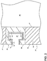
FIG. 2 is a side sectional view of the household cooking appliance ofFIG. 1 along line II-II including a component in the form of a handle. -
FIG. 3 is a schematic view of an insulation film that can be utilized in the component ofFIG. 2 with layers and heat flows illustrated. -
FIG. 4 is a schematic side view of another component for the household cooking appliance ofFIG. 1 in the form of a knob that can include the insulation film ofFIG. 3 . -
FIG. 5 is a flowchart illustrating a method of forming the insulation film ofFIG. 3 . - Aspects of the disclosure relate to a heat-resistant component in the form of an insulation film containing nanowires. Aspects of the disclosure are described in the context of a household cooking appliance, such as an oven. It will be understood that the disclosure is not so limited and can have general applicability, including to any component in a heated environment.
- Some cooking appliances or other heat-generating appliances can include pocket-style handles wherein a user pulls on a recessed portion of a door or access panel adjacent a heated chamber. During operation of the appliance, heat can localize or be trapped within the recessed portion of the pocket handle. This can cause an undesirably high temperature within the recessed portion or on surfaces of the handle that a user might grasp.
-
FIG. 1 illustrates an exemplaryhousehold cooking appliance 10 in the form of an oven. It will be understood that while illustrated as an oven, the household appliance can include any home appliance used for cooking or preparing food, including a toaster oven or cooktop in non-limiting examples. - The
cooking appliance 10 can include acabinet 12 with an open-faced cooking chamber 14 defined by a pair of spacedside walls top wall 20, abottom wall 21 and arear wall 23. Adoor 24 selectively closes thechamber 14. Thedoor 24 in an open position can allow a user to access thechamber 14, while thedoor 24 in a closed position prevents access to thechamber 14 and seals thechamber 14 from the external environment. Ahandle 26 can be provided in thedoor 24 for moving thedoor 24 between open and closed positions. - The
cooking appliance 10 can also include at least oneheating element 30, which is illustrated in the example ofFIG. 1 as being hidden or mounted beneath the cookingchamber bottom wall 22 in aheating element housing 32. Heat from theheating element 30 can conduct through thebottom wall 22 and into thechamber 14. Alternatively, theheating element 30 can be mounted inside thechamber 14, where heat can conduct or radiate inside thechamber 14, such as along theside walls cooking appliance 10 for circulating air or steam within thechamber 14. Afood item 35 can be placed within thechamber 14 to be cooked by thecooking appliance 10. - A human-machine interface or
user interface 40 can also be provided in thecooking appliance 10. Theuser interface 40 can include any suitable interface for input or control of thecooking appliance 10, such as an electronic display or touchscreen display, as well as manually-operated components such as buttons, dials, or switches. In the illustrated example, theuser interface 40 includes aknob 42 and anelectronic panel 44 provided in afront wall 21 of thecabinet 12. Theelectronic panel 44 can include at least one electronically-controlled switch (not shown). It will be understood that theuser interface 40 can include more or fewer components than those shown. - Turning to
FIG. 2 , a side sectional view of thecooking appliance 10 is illustrated. Thedoor 24 can include adoor body 50 with aninner surface 51 thermally confronting thecooking chamber 14 and anouter surface 52 within which thehandle 26 can be located. As used herein, a surface "thermally confronting" thecooking chamber 14 will refer to a surface being thermally coupled to thecooking chamber 14 such that heat within thecooking chamber 14 can be transferred to the surface, including by conduction, convection, or radiation. - In the illustrated example, the
handle 26 is in the form of a "pocket." More specifically, thehandle 26 can include ahandle body 54 with aninner contact surface 55 thermally confronting thecooking chamber 14, as well as anouter handle surface 56 that is flush or coplanar with the doorouter surface 52. Agap 57 can be defined between theinner contact surface 55 andouter handle surface 56. A user can insert a hand into thegap 57 and pull on theinner contact surface 55 to open thedoor 24. In an alternate example (not shown), the handle can be in the form of a bar projecting outward from thedoor 24, wherein a user can grasp the bar and pull to open thedoor 24. - A composite 70 can be disposed on the
inner contact surface 55. The composite 70 can be in the form of an insulation film 76 and include afirst layer 71 and asecond layer 72. Thecomposite 70 can be utilized to prevent excessive heating of thehandle 26 during operation of thecooking appliance 10. Optionally, thecomposite 70 can also be applied to other surfaces of thedoor 24, such as theinner surface 51 or theouter surface 52. - Turning to
FIG. 3 , thecomposite 70 is illustrated in further detail. Thefirst layer 71 of thecomposite 70 can include silver nanowires 73 forming a mesh. In one example the mesh can be a structured fiber mesh, such as a woven fiber mesh with at least one ply. In another example the mesh can be a non-structured mesh wherein the fibers have random orientations within the mesh. Thesecond layer 72 of thecomposite 70 can includeporous alumina 74 with air-filledpores 78 defined within thesecond layer 72. For clarity, someexemplary pores 78 are illustrated and it should be understood that thepores 78 can be arranged throughout thesecond layer 72, including with an ordered or random orientation within thesecond layer 72. In the illustrated example, thefirst layer 71 is proximate theinner contact surface 55 of thehandle 26, and lies between theinner contact surface 55 and thesecond layer 72. - Optionally, a
substrate 75 having asubstrate thickness 77 can be included in thecomposite 70. In one example, thesubstrate 75 can include an adhesive and can be positioned between theinner contact surface 55 andfirst layer 71. Thefirst layer 71 can be proximate to thesubstrate 75, and thesecond layer 72 can be proximate to thefirst layer 71 and distal from thesubstrate 75. It is contemplated that the first andsecond layers substrate 75 can at least partially define the insulation film 76, and can be applied to theinner contact surface 55 of thehandle 26 in one non-limiting example. - The
first layer 71 can be formed of a polymeric material with the silver nanowires 73 dispersed within the polymeric material. Thefirst layer 71 can have afirst layer thickness 81 and anarea density 82. The silver nanowires 73 can have a diameter 83 and a length 84. Anaverage spacing 85 can be defined between adjacent silver nanowires 73. In one non-limiting example, the diameter 83 can be approximately 10-20 nm, including 15-17 nm, theaverage spacing 85 can be approximately 150-200 nm, the length 84 can be approximately 10-80 µm, thefirst layer thickness 81 can be approximately 50-100 µm, and the area density can be 0.15-0.25 g/m2. As used herein, "approximate" or "approximately" will refer to a value that does not differ from a stated numerical value (e.g. 0.2 g/m2) or from a range of numerical values (e.g. 100-400 nm) by more than a predetermined limit. In one example the predetermined limit can be relative, such within 10% of a stated numerical value or a range of numerical values. In another example the predetermined limit can be an absolute limit, such as 1 micrometer or smaller. In still another example the predetermined limit can be based on another parameter, such as theaverage spacing 85 not being more than 10 times the diameter 83 of the silver nanowires 73. - The
second layer 72 can have asecond layer thickness 91, such as between 50-100 µm in a non-limiting example. Anaverage pore size 92 of the porous alumina structure can be defined within thesecond layer 72, such as approximately 10-35 µm, or 22.9 ± 10.3 µm in non-limiting examples. It is contemplated that the composite 70 can have anoverall thickness 93 at least partially defined by the first and second layer thicknesses 81, 91, andsubstrate thickness 77. In one non-limiting example, theoverall thickness 93 can be 200-250 µm. Silver nanowires 73 can also be provided within thesecond layer 72, including with an exemplary diameter 83 of approximately 10-20 nm, a length 84 of approximately 10-80 µm, and anaverage spacing 85 of approximately 150-200 nm in one non-limiting example. - Arrows illustrate heat transfer during operation of the cooking appliance 10 (
FIG. 1 ). Heat shown witharrows 100 from within thecooking chamber 14 can flow toward thefirst layer 71. The mesh of silver nanowires 73 can reflect a portion of the heat, shown byarrow 101, back into thecooking chamber 14. Remaining heat can flow toward thesecond layer 71. The silver nanowires 73 within thesecond layer 72 can reflect a portion of the incoming heat, shown byarrow 102, back toward thecooking chamber 14. In addition, the air-filledpores 78 formed within theporous alumina 74 can block another portion of the incoming heat, shown byarrow 103, from transferring through thesecond layer 72. A very small fraction of heat, shown byarrow 104, can transfer through thesecond layer 72. In this manner, the insulation film 76 can both reflect or "reject" heat from entering alayer layer - Referring now to
FIG. 4 , another component that can be utilized in thecooking appliance 10 is shown in the form of theknob 42 projecting from thefront wall 21. Theknob 42 can include aknob body 60 with aninner surface 62 thermally confronting the chamber 14 (FIG. 2 ), as well as arotatable portion 64 connected to theinner surface 62 by ashaft 66. A user can grasp therotatable portion 64 to operate theknob 42, such as to adjust a temperature setting of thecooking chamber 14. - Insulation film 76 can also be disposed on the
inner surface 62 of theknob 42, such as to prevent excessive heating of theknob 42 during operation of thecooking appliance 10. In one example, the insulation film 76 can be applied to theknob 42 after manufacture of theknob 42, such as by an adhesive or other coupling mechanism. In another example, theknob 42 can be formed integrally with the insulation film 76, such as by placing insulation film 76 into an injection mold prior to forming theknob 42. In such a case, theinner surface 62 of theknob 42 can be injection molded with the insulation film 76 already in place. In the illustrated example, the insulation film 76 is positioned between theinner surface 62 and thefront wall 21, with thefirst layer 71 proximate theinner surface 62 and thesecond layer 72 proximate thefirst layer 71. - Turning to
FIG. 5 , oneexemplary method 110 is described for forming silver nanowires 73 that can be utilized in the insulation film 76. It will be understood that the method described below provides one example of forming the silver nanowires 73. Themethod 110 can include other aspects not explicitly described, and that aspects of themethod 110 can be performed in any suitable order. - The
method 110 can optionally include precursor heating at 112 which can be utilized to grow silver nanowires 73. For example, a solution containing silver nitrate can be heated to a suitable reaction temperature. In one example, silver nanowires with a diameter of 17 ± 2 nm can be obtained at an injection rate of 2.5 mL/s and a reaction temperature of 100 °C. The silver nanowires can have uniform diameters, and lengths varying from approximately 10 microns to approximately 40 microns. Optionally, the silver nanowires can be dispersed into a solvent such as ethanol or ethylene glycol in non-limiting examples. Other surfactants can also be added such as two-system-based pre-polymerized polymer (1:10 ratio). In one example, pre-polymerized liquid silicon can be utilized. One benefit of using such a liquid silicon is that it can cure rapidly at elevated temperatures. In one example, a 2.5 mm cross-section can cure within approximately 10-15 seconds at 200°C. In this manner, a blending matrix can be developed utilizing a pre-polymerized polymer as a blending agent with silver nanowires 73. Unique about this technique is its dispersion performance which is prepared as secondary dispersions or by polyaddition of pre-polymers in aqueous systems. The dispersion process can also be adjusted or tailored based on, in non-limiting examples, solubility or insolubility of monomer and initiator, respectively, the presence or absence of surfactant, droplet sizes, particle sizes, or particle formation mechanisms. - In one non-limiting example of reaction conditions utilizing ethylene, an ethylene pressure of 10 to 40 atm and temperature of 30 °C to 75 °C can be utilized, wherein the ethylene does not form a separate liquid phase under these conditions. The particle sizes (average) of the dispersions obtained can be in the range from 100 to 200 nm. In one example, during formation of a polymer dispersion a sufficiently large number of primary particles were nucleated such that the final particles was sufficiently small to be colloidally stable. A matrix comprises of porous alumina silicate blended with 2-system based pre-polymerized polymer can be prepared separately. It can be appreciated that liquid polymer can be utilized to avoid the overheating of the polymer particle when blended in pelletized form. The use of liquid polymer can also help to reduce particle overheating and agglomeration as well as control particle morphology.
- Exemplary polymers that can be utilized include, in non-limiting examples, polymers and copolymers of acrylic and methacrylic acids and esters, acrylonitrile, and acrylamide. Due to their large polymerization shrinkage, it can be advantageous to carry out their polymerization in stages to control the product dimensions for use in large-surface-area nanomaterials such as silver nanowires. For this, a two-system-based pre-polymerized polymer can be used to prepare a mixture of polymer. Such a pre-polymerized polymer can provide for ease of handling and minimizes abrupt polymerization shrinkage by the use of pre-polymerized powder. The pre-polymerized powder provides for several benefits including no post-curing, excellent electrical insulating properties, easily pigmented, superior unprimed adhesion to glass fabric and extremely suitable for spray-on and dip coating applications.
- The pre-polymerized polymer can be mixed in two parts A and B in a 10:1 ratio. Meter mix equipment can be utilized to pump and mix the two components without excessive incorporation of air into the mixture. In order to avoid air bubble entrapment during their mixing process, the mixture can be thoroughly de-gassed under vacuum to avoid the build-up of voids which may eventually effect the overall thermal performance of the insulation film, especially when used as a blending agent.
- At 114, the
first layer 71 of silver nanowires can be applied to thesubstrate 75. The silver nanowires 73 can be applied by spray deposition, including a spray-on coating technique wherein the silver nanowires 73 are dispersed within pre-polymerized polymer as described above. Optionally, thefirst layer 71 can be pressed onto the substrate, such as via rollers or other mechanisms. - At 116, the
second layer 72 ofporous alumina 74 can be applied to the first layer 712. Optionally, thesecond layer 72 can be pressed onto thefirst layer 71. Theporous alumina 74 can, in one example, include porous alumina silicate formed from kaolinite and bentonite clay powders (natural colloidal, hydrated aluminum silicates) mixed together along with active additives which can be based on magnesium nitrate or aluminum nitrate. The porous alumina silicate can be sintered at very high temperatures (e.g. 1800 °C) to develop a porous ceramic structure with selective microcrystalline and amorphous grain boundaries having energy-efficient thermal insulation properties. The desired fine pores (voids) can be formed by sintering raw ceramic powders at a nondensifying temperature. A high porosity level can be achieved via the addition of large quantities of pore formers such as resin beads and carbon, which can be removed latter through oxidation process. - In one example, the porous alumina ceramic can include silica particles with diameters of about 10 nm to about 15 nm developed by a slip casting technique, wherein an aqueous alumina slurry is used with a control loading concentration of metallic aluminum powder. Porosity of the used base material can aid in chemical reaction of aluminum with water by hydrogen gas evolution reaction and solidification of suspension at a temperature of 1650 - 1750°C. The pore size distribution and mechanical strength the
porous alumina 74 can depend on the grain size of the starting materials. - It can be appreciated that the insulation film 76 can be utilized in a variety of contexts where thermal insulation properties may be desired, including cooking appliance components such as front panels, doors, door handles including pocket-style handles, knobs, other fascia components, and other related applications.
- Aspects of the disclosure provide for several benefits, including that the use of silver nanowires to form a conductive porous network provides for increased reflection of heat, which can reduce the amount of heat able to transfer to the outer surface. For example, during operation of the oven, heat from within the cooking chamber can transfer to outer components of the oven such as a handle or other human-machine interface components such as knobs, switches, touch panels, or the like. It can be appreciated that the insulation film described herein can reduce an amount of heat transfer to components that a user may touch, improving operability of such user interface components.
- In addition, improved chemical stability of silver nanowires make these a suitable material for use as an active ingredient for the proposed heat rejection technology. Silver nanowire meshes can provide for highly effective trapping of thermal radiation, including a high reflectance of thermal radiation from a wide range of incidence angles, such as from approximately 0° (normal/perpendicular incidence) to approximately 85° in a non-limiting example. The insulating film described herein can have significantly improved thermal insulation performance compared to traditional heat reduction components, including a thermal conductivity of approximately 2 W/m-K and a coefficient of thermal expansion of approximately 3.6 µm/m-°C for temperatures ranging from approximately 25°C through 1000°C.
- Another benefit is that the overall emissivity of the layer having a mesh of silver nanowires is comparable to that of porous alumina (approximately 0.80), which is much greater than the emissivity of bulk silver (approximately 0.2) which provides for excellent insulation against radiative heat loss from the chamber.
- In addition, as silver forms only a small fraction of the overall mass of its layer, the insulation film described above provides for a cost-effective solution with excellent insulating properties. Spray-coating a silver nanowire solution can adds a nominal area density of approximately 0.15 g/m2. Aspects of the silver nanowires and layered structures described herein can reflect heat, e.g. infrared radiation, by more than 90% back toward the original heat source and the reported increase in its heat reflectance is due to differences in the materials' emissivity. Low-emissivity materials like silver, which has an emissivity of 0.02, emit less radiation and can provide much better insulation than other high-emissivity materials. Silver nanowires with lengths and spacing distances as described herein can improve film packing and stacking options for forming the insulated film. In addition, the proposed spray coating deposition process provides for a low-cost technique that reduces manufacturing time as well as provides for repeatable populating of silver nanowires within the layers as described.
- To the extent not already described, the different features and structures of the various embodiments can be used in combination, or in substitution with each other as desired. That one feature is not illustrated in all of the embodiments is not meant to be construed that it cannot be so illustrated, but is done for brevity of description. Thus, the various features of the different embodiments can be mixed and matched as desired to form new embodiments, whether or not the new embodiments are expressly described. All combinations or permutations of features described herein are covered by this disclosure. In addition to the concepts covered by the below claims, the following concepts can also provide the basis for claims in any possible combinations:
- An insulation film comprising a substrate, a first layer of silver nanowires proximate to the substrate, and a second layer of porous alumina proximate to the first layer and distal from the substrate.
- An insulation film wherein the first layer comprises a mesh of silver nanowires of 10-20 micrometers in diameter, with a spacing of 150-200 nanometers, an area density of 0.15-0.25 g/m2, and a first layer thickness of 50-100 micrometers, and the second layer has an average pore size of 10-35 micrometers.
- A method of forming an insulation film, the method comprising applying to a substrate a first layer of silver nanowires of 10-20 nm in diameter, at a spacing of 150-200 nm, with an area density of 0.15-0.25 g/m2 and a thickness of 50-100 micrometers, and applying to the first layer a second layer of porous alumina having a thickness of 50-100 micrometers and an average pore size of 10-35 micrometers.
- A method of forming an insulation film wherein the silver nanowires are applied by spray deposition.
- A method of forming an insulation film wherein the spray deposition comprises spraying a liquid polymer of a dispersion of colloidally stable particles of silver nanowires having particle sizes of 100 to 200 nm.
- A method of forming an insulation film further comprising pressing the first layer to the substrate.
- A method of forming an insulation film wherein the pressing occurs prior to the applying of the second layer.
- A method of forming an insulation film further comprising growing the silver nanowires prior to applying the first layer.
- A method of forming an insulation film wherein growing the silver nanowires comprises heating silver nitrate to a reaction temperature.
- A method of forming an insulation film wherein the reaction temperature is at least 100° C.
- A method of forming an insulation film wherein the silver nanowires are grown at a rate of about 2.5 mL/s.
- This written description uses examples to disclose the invention, including the best mode, and also to enable any person skilled in the art to practice the invention, including making and using any devices or systems and performing any incorporated methods. The patentable scope of the invention is defined by the claims, and may include other examples that occur to those skilled in the art. Such other examples are intended to be within the scope of the claims if they have structural elements that do not differ from the literal language of the claims, or if they include equivalent structural elements with insubstantial differences from the literal languages of the claims.
Claims (14)
- A cooking appliance (10) having a cooking chamber (14), said cooking appliance (10 further having a component (24, 26, 42) comprising:a component body (50, 54, 60) defining a surface (51, 52, 55, 62) thermally confronting the cooking chamber (14); anda composite (70) on the surface (51, 52, 55, 62) and comprising:a first layer (71) comprising silver nanowires (73), anda second layer (72) comprising porous alumina (74).
- The cooking appliance (10) of claim 1 wherein the first layer (71) of the component (24, 26, 42) is proximate the surface (51, 52, 55, 62).
- The cooking appliance (10) of any of claims 1-2 wherein the first layer (71) of the component (24, 26, 42) lies between the surface (51, 52, 55, 62) and the second layer (72).
- The cooking appliance (10) of any of claims 1-3 wherein the composite (70) of the component (24, 26, 42) further comprises a substrate (75) between the surface (51, 52, 55, 62) and the first layer (71).
- The cooking appliance (10) of claim 4 wherein said substrate (75) comprises an adhesive.
- The cooking appliance (10) of any of claims 1-5 wherein the first (71) and second (72) layers of the component (24, 26, 42) comprise a film (76) applied to the surface (51, 52, 55, 62).
- The cooking appliance (10) of any of claims 1-6 wherein the silver nanowires (73) form a mesh.
- The cooking appliance (10) of any of claims 1-7 wherein the first layer (71) of the component (24, 26, 42) has a first layer thickness (81) of approximately 50-100 micrometers.
- The cooking appliance (10) of any of claims 1-8 wherein the second layer (72) of the component (24, 26, 42) has a second layer thickness (91) of approximately 50-100 micrometers.
- The cooking appliance (10) of any of claims 1-9 wherein the first layer (71) of the component (24, 26, 42) has an area density (82) of between 0.15 and 0.25 g/m2.
- The cooking appliance (10) of any of claims 1-10 wherein the silver nanowires (73) are 10-20 nm in diameter (83).
- The cooking appliance (10) of any of claims 1-11 wherein the silver nanowires (73) are spaced (85) 150-200 nm.
- The cooking appliance (10) of any of claims 1-12 wherein the porous alumina (74) has an average pore size (92) of 10-35 micrometers.
- The cooking appliance (10) of any of claims 1-13 wherein the first layer (71) of the component (24, 26, 42) comprises a mesh of silver nanowires (73) of 10-20 nm in diameter (83), with a spacing (85) of 150-200 nm, an area density (82) of 0.15-0.25 g/m2, and a first layer thickness (81) of 50-100 micrometers, and wherein the second layer (72) of the component (24, 26, 42) has a second layer thickness (91) of 50-100 micrometers and an average pore size (92) of 10-35 micrometers.
Applications Claiming Priority (1)
| Application Number | Priority Date | Filing Date | Title |
|---|---|---|---|
| US16/242,069 US11236912B2 (en) | 2019-01-08 | 2019-01-08 | Component for cooking appliance |
Publications (2)
| Publication Number | Publication Date |
|---|---|
| EP3680554A1 true EP3680554A1 (en) | 2020-07-15 |
| EP3680554B1 EP3680554B1 (en) | 2021-08-25 |
Family
ID=68886975
Family Applications (1)
| Application Number | Title | Priority Date | Filing Date |
|---|---|---|---|
| EP19215447.4A Active EP3680554B1 (en) | 2019-01-08 | 2019-12-11 | Cooking appliance |
Country Status (3)
| Country | Link |
|---|---|
| US (2) | US11236912B2 (en) |
| EP (1) | EP3680554B1 (en) |
| CN (1) | CN111407159B (en) |
Citations (3)
| Publication number | Priority date | Publication date | Assignee | Title |
|---|---|---|---|---|
| CA1154638A (en) * | 1978-03-15 | 1983-10-04 | Kunio Kimura | Method of forming porcelain enamels |
| CN108995103A (en) * | 2018-08-20 | 2018-12-14 | 中国科学院工程热物理研究所 | Low radiation film and preparation method thereof |
| US10168840B2 (en) * | 2015-01-06 | 2019-01-01 | Samsung Display Co., Ltd | Touch screen panel and method of manufacturing the same |
Family Cites Families (13)
| Publication number | Priority date | Publication date | Assignee | Title |
|---|---|---|---|---|
| DE8133468U1 (en) * | 1981-11-16 | 1982-06-24 | Gebr. Bellmer GmbH + Co KG Maschinenfabrik, 7532 Niefern-Öschelbronn | RAKE, ESPECIALLY FOR WASTEWATER TREATMENT |
| US20040253471A1 (en) * | 2003-05-30 | 2004-12-16 | Thiel James P. | Appliance with coated transparency |
| DE60334414D1 (en) * | 2003-08-13 | 2010-11-11 | All Clad Metalcrafters Llc | BONDED METAL COMPONENTS WITH UNIFORM HEAT CONDUCTIVITY CHARACTERISTICS AND METHOD OF MANUFACTURING THEREOF |
| US8766144B2 (en) * | 2008-07-11 | 2014-07-01 | Electrolux Home Products, Inc. | Cooking appliance and method of cooking a food item |
| DE102010036952A1 (en) | 2010-08-11 | 2012-02-16 | Paul Hettich Gmbh & Co. Kg | Fitting component for a fitting, for a furniture and / or for a household appliance, a furniture, a household appliance, a drawer slide and a method for producing a fitting component |
| CN104194623B (en) | 2014-09-18 | 2016-10-12 | 苏州圣谱拉新材料科技有限公司 | A kind of baking oven high-temperature resistant coating and preparation method thereof |
| CN104473558B (en) * | 2014-12-02 | 2017-02-22 | 苏州鑫精艺钛制品有限公司 | Multi-element composite titanium pot and manufacturing process |
| DE102015111508A1 (en) | 2015-07-16 | 2017-01-19 | Miele & Cie. Kg | Home appliance component |
| US9994715B2 (en) | 2016-02-16 | 2018-06-12 | Sila Nanotechnologies Inc. | Formation and modifications of ceramic nanowires and their use in functional materials |
| CN114424881A (en) * | 2017-03-10 | 2022-05-03 | 李明守 | Intelligent pot |
| CN207341597U (en) * | 2017-05-23 | 2018-05-11 | 新乡职业技术学院 | A kind of interior pot for cooking apparatus |
| CN108981980A (en) * | 2018-05-03 | 2018-12-11 | 五邑大学 | A kind of nanoscale rotary table microstructure pressure sensor and preparation method thereof |
| US20190363010A1 (en) * | 2018-05-23 | 2019-11-28 | Corning Incorporated | Methods of increasing adhesion between a conductive metal and an oxide substrate and articles made therefrom |
-
2019
- 2019-01-08 US US16/242,069 patent/US11236912B2/en active Active
- 2019-12-11 EP EP19215447.4A patent/EP3680554B1/en active Active
- 2019-12-30 CN CN201911394087.4A patent/CN111407159B/en active Active
-
2021
- 2021-12-14 US US17/550,086 patent/US11619396B2/en active Active
Patent Citations (3)
| Publication number | Priority date | Publication date | Assignee | Title |
|---|---|---|---|---|
| CA1154638A (en) * | 1978-03-15 | 1983-10-04 | Kunio Kimura | Method of forming porcelain enamels |
| US10168840B2 (en) * | 2015-01-06 | 2019-01-01 | Samsung Display Co., Ltd | Touch screen panel and method of manufacturing the same |
| CN108995103A (en) * | 2018-08-20 | 2018-12-14 | 中国科学院工程热物理研究所 | Low radiation film and preparation method thereof |
Also Published As
| Publication number | Publication date |
|---|---|
| EP3680554B1 (en) | 2021-08-25 |
| US11236912B2 (en) | 2022-02-01 |
| CN111407159A (en) | 2020-07-14 |
| US11619396B2 (en) | 2023-04-04 |
| CN111407159B (en) | 2022-12-30 |
| US20220107090A1 (en) | 2022-04-07 |
| US20200217516A1 (en) | 2020-07-09 |
Similar Documents
| Publication | Publication Date | Title |
|---|---|---|
| US12401077B2 (en) | Battery thermal management member | |
| US20250293350A1 (en) | Components and systems to manage thermal runaway issues in electric vehicle batteries | |
| CN108602307B (en) | Improved laminates including reinforced aerogel composites | |
| JP2020170707A (en) | Microporous insulator | |
| US20210163303A1 (en) | Aerogel-based components and systems for electric vehicle thermal management | |
| CN102696277A (en) | Method of melt bonding high-temperature thermoplastic based heating element to a substrate | |
| JP7025088B2 (en) | How to make a heat pipe | |
| JP2013050301A (en) | Composite material and device comprising single crystal silicon carbide heated by electromagnetic radiation | |
| EP3654736B1 (en) | Hybrid nanoreinforced liner for microwave oven | |
| JP2016033419A (en) | Manufacturing method of heat insulation plate and vacuum heat insulation material | |
| CN106415107A (en) | vacuum insulation | |
| WO2018039112A1 (en) | Rapid heating rate article and microwave methods | |
| JPH09145241A (en) | Vacuum insulation | |
| US11619396B2 (en) | Insulation film | |
| JP2009041649A (en) | Vacuum heat insulating material and method for manufacturing vacuum heat insulating material | |
| CN110431259A (en) | Manufacturing method and manufacturing apparatus of AlN whisker, AlN whisker structure, AlN whisker, resin molded body, and manufacturing method thereof | |
| JP2004035105A (en) | Coating material and resin for electromagnetic wave heating, and chemical product such as container | |
| CN113831104A (en) | A kind of ultra-high temperature gradient nano thermal insulation material based on reflective screen and preparation method thereof | |
| CN204329612U (en) | A kind of Combined thermal insulative panel for the preparation of stove housing | |
| JP2006064296A (en) | Heat conductive plate formed of expanded graphite and production method therefor | |
| JP2685370B2 (en) | Ceramics heater | |
| CN106341914A (en) | Heat insulation part and heating device comprising same | |
| EP1770324A1 (en) | Heat insulating material | |
| KR20120051512A (en) | Aerogel-open cell foam composite | |
| JP4783489B2 (en) | Silver sintered body manufacturing method and simple furnace |
Legal Events
| Date | Code | Title | Description |
|---|---|---|---|
| PUAI | Public reference made under article 153(3) epc to a published international application that has entered the european phase |
Free format text: ORIGINAL CODE: 0009012 |
|
| STAA | Information on the status of an ep patent application or granted ep patent |
Free format text: STATUS: THE APPLICATION HAS BEEN PUBLISHED |
|
| AK | Designated contracting states |
Kind code of ref document: A1 Designated state(s): AL AT BE BG CH CY CZ DE DK EE ES FI FR GB GR HR HU IE IS IT LI LT LU LV MC MK MT NL NO PL PT RO RS SE SI SK SM TR |
|
| AX | Request for extension of the european patent |
Extension state: BA ME |
|
| STAA | Information on the status of an ep patent application or granted ep patent |
Free format text: STATUS: REQUEST FOR EXAMINATION WAS MADE |
|
| 17P | Request for examination filed |
Effective date: 20210107 |
|
| RBV | Designated contracting states (corrected) |
Designated state(s): AL AT BE BG CH CY CZ DE DK EE ES FI FR GB GR HR HU IE IS IT LI LT LU LV MC MK MT NL NO PL PT RO RS SE SI SK SM TR |
|
| GRAJ | Information related to disapproval of communication of intention to grant by the applicant or resumption of examination proceedings by the epo deleted |
Free format text: ORIGINAL CODE: EPIDOSDIGR1 |
|
| STAA | Information on the status of an ep patent application or granted ep patent |
Free format text: STATUS: GRANT OF PATENT IS INTENDED |
|
| GRAP | Despatch of communication of intention to grant a patent |
Free format text: ORIGINAL CODE: EPIDOSNIGR1 |
|
| GRAS | Grant fee paid |
Free format text: ORIGINAL CODE: EPIDOSNIGR3 |
|
| INTG | Intention to grant announced |
Effective date: 20210621 |
|
| GRAA | (expected) grant |
Free format text: ORIGINAL CODE: 0009210 |
|
| STAA | Information on the status of an ep patent application or granted ep patent |
Free format text: STATUS: THE PATENT HAS BEEN GRANTED |
|
| AK | Designated contracting states |
Kind code of ref document: B1 Designated state(s): AL AT BE BG CH CY CZ DE DK EE ES FI FR GB GR HR HU IE IS IT LI LT LU LV MC MK MT NL NO PL PT RO RS SE SI SK SM TR |
|
| REG | Reference to a national code |
Ref country code: CH Ref legal event code: EP |
|
| REG | Reference to a national code |
Ref country code: IE Ref legal event code: FG4D Ref country code: AT Ref legal event code: REF Ref document number: 1424177 Country of ref document: AT Kind code of ref document: T Effective date: 20210915 |
|
| REG | Reference to a national code |
Ref country code: DE Ref legal event code: R096 Ref document number: 602019007180 Country of ref document: DE |
|
| REG | Reference to a national code |
Ref country code: LT Ref legal event code: MG9D |
|
| REG | Reference to a national code |
Ref country code: NL Ref legal event code: MP Effective date: 20210825 |
|
| REG | Reference to a national code |
Ref country code: AT Ref legal event code: MK05 Ref document number: 1424177 Country of ref document: AT Kind code of ref document: T Effective date: 20210825 |
|
| PG25 | Lapsed in a contracting state [announced via postgrant information from national office to epo] |
Ref country code: SE Free format text: LAPSE BECAUSE OF FAILURE TO SUBMIT A TRANSLATION OF THE DESCRIPTION OR TO PAY THE FEE WITHIN THE PRESCRIBED TIME-LIMIT Effective date: 20210825 Ref country code: RS Free format text: LAPSE BECAUSE OF FAILURE TO SUBMIT A TRANSLATION OF THE DESCRIPTION OR TO PAY THE FEE WITHIN THE PRESCRIBED TIME-LIMIT Effective date: 20210825 Ref country code: ES Free format text: LAPSE BECAUSE OF FAILURE TO SUBMIT A TRANSLATION OF THE DESCRIPTION OR TO PAY THE FEE WITHIN THE PRESCRIBED TIME-LIMIT Effective date: 20210825 Ref country code: FI Free format text: LAPSE BECAUSE OF FAILURE TO SUBMIT A TRANSLATION OF THE DESCRIPTION OR TO PAY THE FEE WITHIN THE PRESCRIBED TIME-LIMIT Effective date: 20210825 Ref country code: HR Free format text: LAPSE BECAUSE OF FAILURE TO SUBMIT A TRANSLATION OF THE DESCRIPTION OR TO PAY THE FEE WITHIN THE PRESCRIBED TIME-LIMIT Effective date: 20210825 Ref country code: PT Free format text: LAPSE BECAUSE OF FAILURE TO SUBMIT A TRANSLATION OF THE DESCRIPTION OR TO PAY THE FEE WITHIN THE PRESCRIBED TIME-LIMIT Effective date: 20211227 Ref country code: NO Free format text: LAPSE BECAUSE OF FAILURE TO SUBMIT A TRANSLATION OF THE DESCRIPTION OR TO PAY THE FEE WITHIN THE PRESCRIBED TIME-LIMIT Effective date: 20211125 Ref country code: AT Free format text: LAPSE BECAUSE OF FAILURE TO SUBMIT A TRANSLATION OF THE DESCRIPTION OR TO PAY THE FEE WITHIN THE PRESCRIBED TIME-LIMIT Effective date: 20210825 Ref country code: BG Free format text: LAPSE BECAUSE OF FAILURE TO SUBMIT A TRANSLATION OF THE DESCRIPTION OR TO PAY THE FEE WITHIN THE PRESCRIBED TIME-LIMIT Effective date: 20211125 Ref country code: LT Free format text: LAPSE BECAUSE OF FAILURE TO SUBMIT A TRANSLATION OF THE DESCRIPTION OR TO PAY THE FEE WITHIN THE PRESCRIBED TIME-LIMIT Effective date: 20210825 |
|
| PG25 | Lapsed in a contracting state [announced via postgrant information from national office to epo] |
Ref country code: PL Free format text: LAPSE BECAUSE OF FAILURE TO SUBMIT A TRANSLATION OF THE DESCRIPTION OR TO PAY THE FEE WITHIN THE PRESCRIBED TIME-LIMIT Effective date: 20210825 Ref country code: LV Free format text: LAPSE BECAUSE OF FAILURE TO SUBMIT A TRANSLATION OF THE DESCRIPTION OR TO PAY THE FEE WITHIN THE PRESCRIBED TIME-LIMIT Effective date: 20210825 Ref country code: GR Free format text: LAPSE BECAUSE OF FAILURE TO SUBMIT A TRANSLATION OF THE DESCRIPTION OR TO PAY THE FEE WITHIN THE PRESCRIBED TIME-LIMIT Effective date: 20211126 |
|
| PG25 | Lapsed in a contracting state [announced via postgrant information from national office to epo] |
Ref country code: NL Free format text: LAPSE BECAUSE OF FAILURE TO SUBMIT A TRANSLATION OF THE DESCRIPTION OR TO PAY THE FEE WITHIN THE PRESCRIBED TIME-LIMIT Effective date: 20210825 |
|
| PG25 | Lapsed in a contracting state [announced via postgrant information from national office to epo] |
Ref country code: DK Free format text: LAPSE BECAUSE OF FAILURE TO SUBMIT A TRANSLATION OF THE DESCRIPTION OR TO PAY THE FEE WITHIN THE PRESCRIBED TIME-LIMIT Effective date: 20210825 |
|
| REG | Reference to a national code |
Ref country code: DE Ref legal event code: R097 Ref document number: 602019007180 Country of ref document: DE |
|
| PG25 | Lapsed in a contracting state [announced via postgrant information from national office to epo] |
Ref country code: SM Free format text: LAPSE BECAUSE OF FAILURE TO SUBMIT A TRANSLATION OF THE DESCRIPTION OR TO PAY THE FEE WITHIN THE PRESCRIBED TIME-LIMIT Effective date: 20210825 Ref country code: SK Free format text: LAPSE BECAUSE OF FAILURE TO SUBMIT A TRANSLATION OF THE DESCRIPTION OR TO PAY THE FEE WITHIN THE PRESCRIBED TIME-LIMIT Effective date: 20210825 Ref country code: RO Free format text: LAPSE BECAUSE OF FAILURE TO SUBMIT A TRANSLATION OF THE DESCRIPTION OR TO PAY THE FEE WITHIN THE PRESCRIBED TIME-LIMIT Effective date: 20210825 Ref country code: EE Free format text: LAPSE BECAUSE OF FAILURE TO SUBMIT A TRANSLATION OF THE DESCRIPTION OR TO PAY THE FEE WITHIN THE PRESCRIBED TIME-LIMIT Effective date: 20210825 Ref country code: CZ Free format text: LAPSE BECAUSE OF FAILURE TO SUBMIT A TRANSLATION OF THE DESCRIPTION OR TO PAY THE FEE WITHIN THE PRESCRIBED TIME-LIMIT Effective date: 20210825 Ref country code: AL Free format text: LAPSE BECAUSE OF FAILURE TO SUBMIT A TRANSLATION OF THE DESCRIPTION OR TO PAY THE FEE WITHIN THE PRESCRIBED TIME-LIMIT Effective date: 20210825 |
|
| PLBE | No opposition filed within time limit |
Free format text: ORIGINAL CODE: 0009261 |
|
| STAA | Information on the status of an ep patent application or granted ep patent |
Free format text: STATUS: NO OPPOSITION FILED WITHIN TIME LIMIT |
|
| PG25 | Lapsed in a contracting state [announced via postgrant information from national office to epo] |
Ref country code: MC Free format text: LAPSE BECAUSE OF FAILURE TO SUBMIT A TRANSLATION OF THE DESCRIPTION OR TO PAY THE FEE WITHIN THE PRESCRIBED TIME-LIMIT Effective date: 20210825 |
|
| 26N | No opposition filed |
Effective date: 20220527 |
|
| PG25 | Lapsed in a contracting state [announced via postgrant information from national office to epo] |
Ref country code: SI Free format text: LAPSE BECAUSE OF FAILURE TO SUBMIT A TRANSLATION OF THE DESCRIPTION OR TO PAY THE FEE WITHIN THE PRESCRIBED TIME-LIMIT Effective date: 20210825 |
|
| REG | Reference to a national code |
Ref country code: BE Ref legal event code: MM Effective date: 20211231 |
|
| PG25 | Lapsed in a contracting state [announced via postgrant information from national office to epo] |
Ref country code: LU Free format text: LAPSE BECAUSE OF NON-PAYMENT OF DUE FEES Effective date: 20211211 Ref country code: IE Free format text: LAPSE BECAUSE OF NON-PAYMENT OF DUE FEES Effective date: 20211211 |
|
| PG25 | Lapsed in a contracting state [announced via postgrant information from national office to epo] |
Ref country code: BE Free format text: LAPSE BECAUSE OF NON-PAYMENT OF DUE FEES Effective date: 20211231 |
|
| P01 | Opt-out of the competence of the unified patent court (upc) registered |
Effective date: 20230522 |
|
| PG25 | Lapsed in a contracting state [announced via postgrant information from national office to epo] |
Ref country code: CY Free format text: LAPSE BECAUSE OF FAILURE TO SUBMIT A TRANSLATION OF THE DESCRIPTION OR TO PAY THE FEE WITHIN THE PRESCRIBED TIME-LIMIT Effective date: 20210825 |
|
| PG25 | Lapsed in a contracting state [announced via postgrant information from national office to epo] |
Ref country code: HU Free format text: LAPSE BECAUSE OF FAILURE TO SUBMIT A TRANSLATION OF THE DESCRIPTION OR TO PAY THE FEE WITHIN THE PRESCRIBED TIME-LIMIT; INVALID AB INITIO Effective date: 20191211 |
|
| REG | Reference to a national code |
Ref country code: CH Ref legal event code: PL |
|
| PG25 | Lapsed in a contracting state [announced via postgrant information from national office to epo] |
Ref country code: LI Free format text: LAPSE BECAUSE OF NON-PAYMENT OF DUE FEES Effective date: 20221231 Ref country code: CH Free format text: LAPSE BECAUSE OF NON-PAYMENT OF DUE FEES Effective date: 20221231 |
|
| PG25 | Lapsed in a contracting state [announced via postgrant information from national office to epo] |
Ref country code: MK Free format text: LAPSE BECAUSE OF FAILURE TO SUBMIT A TRANSLATION OF THE DESCRIPTION OR TO PAY THE FEE WITHIN THE PRESCRIBED TIME-LIMIT Effective date: 20210825 |
|
| PG25 | Lapsed in a contracting state [announced via postgrant information from national office to epo] |
Ref country code: MT Free format text: LAPSE BECAUSE OF FAILURE TO SUBMIT A TRANSLATION OF THE DESCRIPTION OR TO PAY THE FEE WITHIN THE PRESCRIBED TIME-LIMIT Effective date: 20210825 |
|
| PGFP | Annual fee paid to national office [announced via postgrant information from national office to epo] |
Ref country code: GB Payment date: 20241218 Year of fee payment: 6 |
|
| PGFP | Annual fee paid to national office [announced via postgrant information from national office to epo] |
Ref country code: FR Payment date: 20241227 Year of fee payment: 6 |
|
| PGFP | Annual fee paid to national office [announced via postgrant information from national office to epo] |
Ref country code: IT Payment date: 20241220 Year of fee payment: 6 |
|
| PGFP | Annual fee paid to national office [announced via postgrant information from national office to epo] |
Ref country code: DE Payment date: 20241227 Year of fee payment: 6 |
|
| PG25 | Lapsed in a contracting state [announced via postgrant information from national office to epo] |
Ref country code: TR Free format text: LAPSE BECAUSE OF FAILURE TO SUBMIT A TRANSLATION OF THE DESCRIPTION OR TO PAY THE FEE WITHIN THE PRESCRIBED TIME-LIMIT Effective date: 20210825 |