EP3680543B1 - Dispositif et procédé de remplissage de réservoirs de gaz sous pression - Google Patents
Dispositif et procédé de remplissage de réservoirs de gaz sous pression Download PDFInfo
- Publication number
- EP3680543B1 EP3680543B1 EP19215506.7A EP19215506A EP3680543B1 EP 3680543 B1 EP3680543 B1 EP 3680543B1 EP 19215506 A EP19215506 A EP 19215506A EP 3680543 B1 EP3680543 B1 EP 3680543B1
- Authority
- EP
- European Patent Office
- Prior art keywords
- loop
- buffer storage
- compressor
- storage container
- pressurized gas
- Prior art date
- Legal status (The legal status is an assumption and is not a legal conclusion. Google has not performed a legal analysis and makes no representation as to the accuracy of the status listed.)
- Active
Links
Images

Classifications
-
- F—MECHANICAL ENGINEERING; LIGHTING; HEATING; WEAPONS; BLASTING
- F17—STORING OR DISTRIBUTING GASES OR LIQUIDS
- F17C—VESSELS FOR CONTAINING OR STORING COMPRESSED, LIQUEFIED OR SOLIDIFIED GASES; FIXED-CAPACITY GAS-HOLDERS; FILLING VESSELS WITH, OR DISCHARGING FROM VESSELS, COMPRESSED, LIQUEFIED, OR SOLIDIFIED GASES
- F17C13/00—Details of vessels or of the filling or discharging of vessels
- F17C13/04—Arrangement or mounting of valves
- F17C13/045—Automatic change-over switching assembly for bottled gas systems with two (or more) gas containers
-
- F—MECHANICAL ENGINEERING; LIGHTING; HEATING; WEAPONS; BLASTING
- F17—STORING OR DISTRIBUTING GASES OR LIQUIDS
- F17C—VESSELS FOR CONTAINING OR STORING COMPRESSED, LIQUEFIED OR SOLIDIFIED GASES; FIXED-CAPACITY GAS-HOLDERS; FILLING VESSELS WITH, OR DISCHARGING FROM VESSELS, COMPRESSED, LIQUEFIED, OR SOLIDIFIED GASES
- F17C5/00—Methods or apparatus for filling containers with liquefied, solidified, or compressed gases under pressures
- F17C5/06—Methods or apparatus for filling containers with liquefied, solidified, or compressed gases under pressures for filling with compressed gases
-
- F—MECHANICAL ENGINEERING; LIGHTING; HEATING; WEAPONS; BLASTING
- F17—STORING OR DISTRIBUTING GASES OR LIQUIDS
- F17C—VESSELS FOR CONTAINING OR STORING COMPRESSED, LIQUEFIED OR SOLIDIFIED GASES; FIXED-CAPACITY GAS-HOLDERS; FILLING VESSELS WITH, OR DISCHARGING FROM VESSELS, COMPRESSED, LIQUEFIED, OR SOLIDIFIED GASES
- F17C1/00—Pressure vessels, e.g. gas cylinder, gas tank, replaceable cartridge
- F17C1/005—Storage of gas or gaseous mixture at high pressure and at high density condition, e.g. in the single state phase
-
- F—MECHANICAL ENGINEERING; LIGHTING; HEATING; WEAPONS; BLASTING
- F17—STORING OR DISTRIBUTING GASES OR LIQUIDS
- F17C—VESSELS FOR CONTAINING OR STORING COMPRESSED, LIQUEFIED OR SOLIDIFIED GASES; FIXED-CAPACITY GAS-HOLDERS; FILLING VESSELS WITH, OR DISCHARGING FROM VESSELS, COMPRESSED, LIQUEFIED, OR SOLIDIFIED GASES
- F17C13/00—Details of vessels or of the filling or discharging of vessels
-
- F—MECHANICAL ENGINEERING; LIGHTING; HEATING; WEAPONS; BLASTING
- F17—STORING OR DISTRIBUTING GASES OR LIQUIDS
- F17C—VESSELS FOR CONTAINING OR STORING COMPRESSED, LIQUEFIED OR SOLIDIFIED GASES; FIXED-CAPACITY GAS-HOLDERS; FILLING VESSELS WITH, OR DISCHARGING FROM VESSELS, COMPRESSED, LIQUEFIED, OR SOLIDIFIED GASES
- F17C13/00—Details of vessels or of the filling or discharging of vessels
- F17C13/02—Special adaptations of indicating, measuring, or monitoring equipment
-
- F—MECHANICAL ENGINEERING; LIGHTING; HEATING; WEAPONS; BLASTING
- F17—STORING OR DISTRIBUTING GASES OR LIQUIDS
- F17C—VESSELS FOR CONTAINING OR STORING COMPRESSED, LIQUEFIED OR SOLIDIFIED GASES; FIXED-CAPACITY GAS-HOLDERS; FILLING VESSELS WITH, OR DISCHARGING FROM VESSELS, COMPRESSED, LIQUEFIED, OR SOLIDIFIED GASES
- F17C13/00—Details of vessels or of the filling or discharging of vessels
- F17C13/04—Arrangement or mounting of valves
-
- B—PERFORMING OPERATIONS; TRANSPORTING
- B60—VEHICLES IN GENERAL
- B60K—ARRANGEMENT OR MOUNTING OF PROPULSION UNITS OR OF TRANSMISSIONS IN VEHICLES; ARRANGEMENT OR MOUNTING OF PLURAL DIVERSE PRIME-MOVERS IN VEHICLES; AUXILIARY DRIVES FOR VEHICLES; INSTRUMENTATION OR DASHBOARDS FOR VEHICLES; ARRANGEMENTS IN CONNECTION WITH COOLING, AIR INTAKE, GAS EXHAUST OR FUEL SUPPLY OF PROPULSION UNITS IN VEHICLES
- B60K15/00—Arrangement in connection with fuel supply of combustion engines or other fuel consuming energy converters, e.g. fuel cells; Mounting or construction of fuel tanks
- B60K15/03—Fuel tanks
- B60K15/03006—Gas tanks
-
- B—PERFORMING OPERATIONS; TRANSPORTING
- B60—VEHICLES IN GENERAL
- B60K—ARRANGEMENT OR MOUNTING OF PROPULSION UNITS OR OF TRANSMISSIONS IN VEHICLES; ARRANGEMENT OR MOUNTING OF PLURAL DIVERSE PRIME-MOVERS IN VEHICLES; AUXILIARY DRIVES FOR VEHICLES; INSTRUMENTATION OR DASHBOARDS FOR VEHICLES; ARRANGEMENTS IN CONNECTION WITH COOLING, AIR INTAKE, GAS EXHAUST OR FUEL SUPPLY OF PROPULSION UNITS IN VEHICLES
- B60K15/00—Arrangement in connection with fuel supply of combustion engines or other fuel consuming energy converters, e.g. fuel cells; Mounting or construction of fuel tanks
- B60K15/03—Fuel tanks
- B60K2015/03309—Tanks specially adapted for particular fuels
- B60K2015/03315—Tanks specially adapted for particular fuels for hydrogen
-
- F—MECHANICAL ENGINEERING; LIGHTING; HEATING; WEAPONS; BLASTING
- F17—STORING OR DISTRIBUTING GASES OR LIQUIDS
- F17C—VESSELS FOR CONTAINING OR STORING COMPRESSED, LIQUEFIED OR SOLIDIFIED GASES; FIXED-CAPACITY GAS-HOLDERS; FILLING VESSELS WITH, OR DISCHARGING FROM VESSELS, COMPRESSED, LIQUEFIED, OR SOLIDIFIED GASES
- F17C2201/00—Vessel construction, in particular geometry, arrangement or size
- F17C2201/05—Size
- F17C2201/054—Size medium (>1 m3)
-
- F—MECHANICAL ENGINEERING; LIGHTING; HEATING; WEAPONS; BLASTING
- F17—STORING OR DISTRIBUTING GASES OR LIQUIDS
- F17C—VESSELS FOR CONTAINING OR STORING COMPRESSED, LIQUEFIED OR SOLIDIFIED GASES; FIXED-CAPACITY GAS-HOLDERS; FILLING VESSELS WITH, OR DISCHARGING FROM VESSELS, COMPRESSED, LIQUEFIED, OR SOLIDIFIED GASES
- F17C2205/00—Vessel construction, in particular mounting arrangements, attachments or identifications means
- F17C2205/01—Mounting arrangements
- F17C2205/0123—Mounting arrangements characterised by number of vessels
- F17C2205/013—Two or more vessels
-
- F—MECHANICAL ENGINEERING; LIGHTING; HEATING; WEAPONS; BLASTING
- F17—STORING OR DISTRIBUTING GASES OR LIQUIDS
- F17C—VESSELS FOR CONTAINING OR STORING COMPRESSED, LIQUEFIED OR SOLIDIFIED GASES; FIXED-CAPACITY GAS-HOLDERS; FILLING VESSELS WITH, OR DISCHARGING FROM VESSELS, COMPRESSED, LIQUEFIED, OR SOLIDIFIED GASES
- F17C2205/00—Vessel construction, in particular mounting arrangements, attachments or identifications means
- F17C2205/01—Mounting arrangements
- F17C2205/0123—Mounting arrangements characterised by number of vessels
- F17C2205/013—Two or more vessels
- F17C2205/0134—Two or more vessels characterised by the presence of fluid connection between vessels
- F17C2205/0142—Two or more vessels characterised by the presence of fluid connection between vessels bundled in parallel
-
- F—MECHANICAL ENGINEERING; LIGHTING; HEATING; WEAPONS; BLASTING
- F17—STORING OR DISTRIBUTING GASES OR LIQUIDS
- F17C—VESSELS FOR CONTAINING OR STORING COMPRESSED, LIQUEFIED OR SOLIDIFIED GASES; FIXED-CAPACITY GAS-HOLDERS; FILLING VESSELS WITH, OR DISCHARGING FROM VESSELS, COMPRESSED, LIQUEFIED, OR SOLIDIFIED GASES
- F17C2205/00—Vessel construction, in particular mounting arrangements, attachments or identifications means
- F17C2205/03—Fluid connections, filters, valves, closure means or other attachments
- F17C2205/0302—Fittings, valves, filters, or components in connection with the gas storage device
- F17C2205/0323—Valves
-
- F—MECHANICAL ENGINEERING; LIGHTING; HEATING; WEAPONS; BLASTING
- F17—STORING OR DISTRIBUTING GASES OR LIQUIDS
- F17C—VESSELS FOR CONTAINING OR STORING COMPRESSED, LIQUEFIED OR SOLIDIFIED GASES; FIXED-CAPACITY GAS-HOLDERS; FILLING VESSELS WITH, OR DISCHARGING FROM VESSELS, COMPRESSED, LIQUEFIED, OR SOLIDIFIED GASES
- F17C2205/00—Vessel construction, in particular mounting arrangements, attachments or identifications means
- F17C2205/03—Fluid connections, filters, valves, closure means or other attachments
- F17C2205/0302—Fittings, valves, filters, or components in connection with the gas storage device
- F17C2205/0352—Pipes
- F17C2205/0364—Pipes flexible or articulated, e.g. a hose
-
- F—MECHANICAL ENGINEERING; LIGHTING; HEATING; WEAPONS; BLASTING
- F17—STORING OR DISTRIBUTING GASES OR LIQUIDS
- F17C—VESSELS FOR CONTAINING OR STORING COMPRESSED, LIQUEFIED OR SOLIDIFIED GASES; FIXED-CAPACITY GAS-HOLDERS; FILLING VESSELS WITH, OR DISCHARGING FROM VESSELS, COMPRESSED, LIQUEFIED, OR SOLIDIFIED GASES
- F17C2221/00—Handled fluid, in particular type of fluid
- F17C2221/01—Pure fluids
- F17C2221/012—Hydrogen
-
- F—MECHANICAL ENGINEERING; LIGHTING; HEATING; WEAPONS; BLASTING
- F17—STORING OR DISTRIBUTING GASES OR LIQUIDS
- F17C—VESSELS FOR CONTAINING OR STORING COMPRESSED, LIQUEFIED OR SOLIDIFIED GASES; FIXED-CAPACITY GAS-HOLDERS; FILLING VESSELS WITH, OR DISCHARGING FROM VESSELS, COMPRESSED, LIQUEFIED, OR SOLIDIFIED GASES
- F17C2223/00—Handled fluid before transfer, i.e. state of fluid when stored in the vessel or before transfer from the vessel
- F17C2223/01—Handled fluid before transfer, i.e. state of fluid when stored in the vessel or before transfer from the vessel characterised by the phase
- F17C2223/0107—Single phase
- F17C2223/0123—Single phase gaseous, e.g. CNG, GNC
-
- F—MECHANICAL ENGINEERING; LIGHTING; HEATING; WEAPONS; BLASTING
- F17—STORING OR DISTRIBUTING GASES OR LIQUIDS
- F17C—VESSELS FOR CONTAINING OR STORING COMPRESSED, LIQUEFIED OR SOLIDIFIED GASES; FIXED-CAPACITY GAS-HOLDERS; FILLING VESSELS WITH, OR DISCHARGING FROM VESSELS, COMPRESSED, LIQUEFIED, OR SOLIDIFIED GASES
- F17C2223/00—Handled fluid before transfer, i.e. state of fluid when stored in the vessel or before transfer from the vessel
- F17C2223/01—Handled fluid before transfer, i.e. state of fluid when stored in the vessel or before transfer from the vessel characterised by the phase
- F17C2223/0146—Two-phase
- F17C2223/0153—Liquefied gas, e.g. LPG, GPL
- F17C2223/0161—Liquefied gas, e.g. LPG, GPL cryogenic, e.g. LNG, GNL, PLNG
-
- F—MECHANICAL ENGINEERING; LIGHTING; HEATING; WEAPONS; BLASTING
- F17—STORING OR DISTRIBUTING GASES OR LIQUIDS
- F17C—VESSELS FOR CONTAINING OR STORING COMPRESSED, LIQUEFIED OR SOLIDIFIED GASES; FIXED-CAPACITY GAS-HOLDERS; FILLING VESSELS WITH, OR DISCHARGING FROM VESSELS, COMPRESSED, LIQUEFIED, OR SOLIDIFIED GASES
- F17C2223/00—Handled fluid before transfer, i.e. state of fluid when stored in the vessel or before transfer from the vessel
- F17C2223/03—Handled fluid before transfer, i.e. state of fluid when stored in the vessel or before transfer from the vessel characterised by the pressure level
- F17C2223/033—Small pressure, e.g. for liquefied gas
-
- F—MECHANICAL ENGINEERING; LIGHTING; HEATING; WEAPONS; BLASTING
- F17—STORING OR DISTRIBUTING GASES OR LIQUIDS
- F17C—VESSELS FOR CONTAINING OR STORING COMPRESSED, LIQUEFIED OR SOLIDIFIED GASES; FIXED-CAPACITY GAS-HOLDERS; FILLING VESSELS WITH, OR DISCHARGING FROM VESSELS, COMPRESSED, LIQUEFIED, OR SOLIDIFIED GASES
- F17C2223/00—Handled fluid before transfer, i.e. state of fluid when stored in the vessel or before transfer from the vessel
- F17C2223/03—Handled fluid before transfer, i.e. state of fluid when stored in the vessel or before transfer from the vessel characterised by the pressure level
- F17C2223/036—Very high pressure (>80 bar)
-
- F—MECHANICAL ENGINEERING; LIGHTING; HEATING; WEAPONS; BLASTING
- F17—STORING OR DISTRIBUTING GASES OR LIQUIDS
- F17C—VESSELS FOR CONTAINING OR STORING COMPRESSED, LIQUEFIED OR SOLIDIFIED GASES; FIXED-CAPACITY GAS-HOLDERS; FILLING VESSELS WITH, OR DISCHARGING FROM VESSELS, COMPRESSED, LIQUEFIED, OR SOLIDIFIED GASES
- F17C2225/00—Handled fluid after transfer, i.e. state of fluid after transfer from the vessel
- F17C2225/01—Handled fluid after transfer, i.e. state of fluid after transfer from the vessel characterised by the phase
- F17C2225/0107—Single phase
- F17C2225/0123—Single phase gaseous, e.g. CNG, GNC
-
- F—MECHANICAL ENGINEERING; LIGHTING; HEATING; WEAPONS; BLASTING
- F17—STORING OR DISTRIBUTING GASES OR LIQUIDS
- F17C—VESSELS FOR CONTAINING OR STORING COMPRESSED, LIQUEFIED OR SOLIDIFIED GASES; FIXED-CAPACITY GAS-HOLDERS; FILLING VESSELS WITH, OR DISCHARGING FROM VESSELS, COMPRESSED, LIQUEFIED, OR SOLIDIFIED GASES
- F17C2225/00—Handled fluid after transfer, i.e. state of fluid after transfer from the vessel
- F17C2225/03—Handled fluid after transfer, i.e. state of fluid after transfer from the vessel characterised by the pressure level
- F17C2225/036—Very high pressure, i.e. above 80 bars
-
- F—MECHANICAL ENGINEERING; LIGHTING; HEATING; WEAPONS; BLASTING
- F17—STORING OR DISTRIBUTING GASES OR LIQUIDS
- F17C—VESSELS FOR CONTAINING OR STORING COMPRESSED, LIQUEFIED OR SOLIDIFIED GASES; FIXED-CAPACITY GAS-HOLDERS; FILLING VESSELS WITH, OR DISCHARGING FROM VESSELS, COMPRESSED, LIQUEFIED, OR SOLIDIFIED GASES
- F17C2227/00—Transfer of fluids, i.e. method or means for transferring the fluid; Heat exchange with the fluid
- F17C2227/01—Propulsion of the fluid
- F17C2227/0128—Propulsion of the fluid with pumps or compressors
- F17C2227/0157—Compressors
-
- F—MECHANICAL ENGINEERING; LIGHTING; HEATING; WEAPONS; BLASTING
- F17—STORING OR DISTRIBUTING GASES OR LIQUIDS
- F17C—VESSELS FOR CONTAINING OR STORING COMPRESSED, LIQUEFIED OR SOLIDIFIED GASES; FIXED-CAPACITY GAS-HOLDERS; FILLING VESSELS WITH, OR DISCHARGING FROM VESSELS, COMPRESSED, LIQUEFIED, OR SOLIDIFIED GASES
- F17C2227/00—Transfer of fluids, i.e. method or means for transferring the fluid; Heat exchange with the fluid
- F17C2227/01—Propulsion of the fluid
- F17C2227/0128—Propulsion of the fluid with pumps or compressors
- F17C2227/0171—Arrangement
- F17C2227/0185—Arrangement comprising several pumps or compressors
-
- F—MECHANICAL ENGINEERING; LIGHTING; HEATING; WEAPONS; BLASTING
- F17—STORING OR DISTRIBUTING GASES OR LIQUIDS
- F17C—VESSELS FOR CONTAINING OR STORING COMPRESSED, LIQUEFIED OR SOLIDIFIED GASES; FIXED-CAPACITY GAS-HOLDERS; FILLING VESSELS WITH, OR DISCHARGING FROM VESSELS, COMPRESSED, LIQUEFIED, OR SOLIDIFIED GASES
- F17C2227/00—Transfer of fluids, i.e. method or means for transferring the fluid; Heat exchange with the fluid
- F17C2227/04—Methods for emptying or filling
- F17C2227/041—Methods for emptying or filling vessel by vessel
- F17C2227/042—Methods for emptying or filling vessel by vessel with change-over from one vessel to another
-
- F—MECHANICAL ENGINEERING; LIGHTING; HEATING; WEAPONS; BLASTING
- F17—STORING OR DISTRIBUTING GASES OR LIQUIDS
- F17C—VESSELS FOR CONTAINING OR STORING COMPRESSED, LIQUEFIED OR SOLIDIFIED GASES; FIXED-CAPACITY GAS-HOLDERS; FILLING VESSELS WITH, OR DISCHARGING FROM VESSELS, COMPRESSED, LIQUEFIED, OR SOLIDIFIED GASES
- F17C2227/00—Transfer of fluids, i.e. method or means for transferring the fluid; Heat exchange with the fluid
- F17C2227/04—Methods for emptying or filling
- F17C2227/043—Methods for emptying or filling by pressure cascade
-
- F—MECHANICAL ENGINEERING; LIGHTING; HEATING; WEAPONS; BLASTING
- F17—STORING OR DISTRIBUTING GASES OR LIQUIDS
- F17C—VESSELS FOR CONTAINING OR STORING COMPRESSED, LIQUEFIED OR SOLIDIFIED GASES; FIXED-CAPACITY GAS-HOLDERS; FILLING VESSELS WITH, OR DISCHARGING FROM VESSELS, COMPRESSED, LIQUEFIED, OR SOLIDIFIED GASES
- F17C2250/00—Accessories; Control means; Indicating, measuring or monitoring of parameters
- F17C2250/01—Intermediate tanks
-
- F—MECHANICAL ENGINEERING; LIGHTING; HEATING; WEAPONS; BLASTING
- F17—STORING OR DISTRIBUTING GASES OR LIQUIDS
- F17C—VESSELS FOR CONTAINING OR STORING COMPRESSED, LIQUEFIED OR SOLIDIFIED GASES; FIXED-CAPACITY GAS-HOLDERS; FILLING VESSELS WITH, OR DISCHARGING FROM VESSELS, COMPRESSED, LIQUEFIED, OR SOLIDIFIED GASES
- F17C2250/00—Accessories; Control means; Indicating, measuring or monitoring of parameters
- F17C2250/03—Control means
- F17C2250/032—Control means using computers
-
- F—MECHANICAL ENGINEERING; LIGHTING; HEATING; WEAPONS; BLASTING
- F17—STORING OR DISTRIBUTING GASES OR LIQUIDS
- F17C—VESSELS FOR CONTAINING OR STORING COMPRESSED, LIQUEFIED OR SOLIDIFIED GASES; FIXED-CAPACITY GAS-HOLDERS; FILLING VESSELS WITH, OR DISCHARGING FROM VESSELS, COMPRESSED, LIQUEFIED, OR SOLIDIFIED GASES
- F17C2250/00—Accessories; Control means; Indicating, measuring or monitoring of parameters
- F17C2250/06—Controlling or regulating of parameters as output values
- F17C2250/0605—Parameters
- F17C2250/0626—Pressure
-
- F—MECHANICAL ENGINEERING; LIGHTING; HEATING; WEAPONS; BLASTING
- F17—STORING OR DISTRIBUTING GASES OR LIQUIDS
- F17C—VESSELS FOR CONTAINING OR STORING COMPRESSED, LIQUEFIED OR SOLIDIFIED GASES; FIXED-CAPACITY GAS-HOLDERS; FILLING VESSELS WITH, OR DISCHARGING FROM VESSELS, COMPRESSED, LIQUEFIED, OR SOLIDIFIED GASES
- F17C2250/00—Accessories; Control means; Indicating, measuring or monitoring of parameters
- F17C2250/06—Controlling or regulating of parameters as output values
- F17C2250/0605—Parameters
- F17C2250/0631—Temperature
-
- F—MECHANICAL ENGINEERING; LIGHTING; HEATING; WEAPONS; BLASTING
- F17—STORING OR DISTRIBUTING GASES OR LIQUIDS
- F17C—VESSELS FOR CONTAINING OR STORING COMPRESSED, LIQUEFIED OR SOLIDIFIED GASES; FIXED-CAPACITY GAS-HOLDERS; FILLING VESSELS WITH, OR DISCHARGING FROM VESSELS, COMPRESSED, LIQUEFIED, OR SOLIDIFIED GASES
- F17C2250/00—Accessories; Control means; Indicating, measuring or monitoring of parameters
- F17C2250/06—Controlling or regulating of parameters as output values
- F17C2250/0605—Parameters
- F17C2250/0636—Flow or movement of content
-
- F—MECHANICAL ENGINEERING; LIGHTING; HEATING; WEAPONS; BLASTING
- F17—STORING OR DISTRIBUTING GASES OR LIQUIDS
- F17C—VESSELS FOR CONTAINING OR STORING COMPRESSED, LIQUEFIED OR SOLIDIFIED GASES; FIXED-CAPACITY GAS-HOLDERS; FILLING VESSELS WITH, OR DISCHARGING FROM VESSELS, COMPRESSED, LIQUEFIED, OR SOLIDIFIED GASES
- F17C2260/00—Purposes of gas storage and gas handling
- F17C2260/02—Improving properties related to fluid or fluid transfer
- F17C2260/025—Reducing transfer time
-
- F—MECHANICAL ENGINEERING; LIGHTING; HEATING; WEAPONS; BLASTING
- F17—STORING OR DISTRIBUTING GASES OR LIQUIDS
- F17C—VESSELS FOR CONTAINING OR STORING COMPRESSED, LIQUEFIED OR SOLIDIFIED GASES; FIXED-CAPACITY GAS-HOLDERS; FILLING VESSELS WITH, OR DISCHARGING FROM VESSELS, COMPRESSED, LIQUEFIED, OR SOLIDIFIED GASES
- F17C2265/00—Effects achieved by gas storage or gas handling
- F17C2265/06—Fluid distribution
- F17C2265/065—Fluid distribution for refuelling vehicle fuel tanks
-
- F—MECHANICAL ENGINEERING; LIGHTING; HEATING; WEAPONS; BLASTING
- F17—STORING OR DISTRIBUTING GASES OR LIQUIDS
- F17C—VESSELS FOR CONTAINING OR STORING COMPRESSED, LIQUEFIED OR SOLIDIFIED GASES; FIXED-CAPACITY GAS-HOLDERS; FILLING VESSELS WITH, OR DISCHARGING FROM VESSELS, COMPRESSED, LIQUEFIED, OR SOLIDIFIED GASES
- F17C2270/00—Applications
- F17C2270/01—Applications for fluid transport or storage
- F17C2270/0134—Applications for fluid transport or storage placed above the ground
- F17C2270/0139—Fuel stations
-
- F—MECHANICAL ENGINEERING; LIGHTING; HEATING; WEAPONS; BLASTING
- F17—STORING OR DISTRIBUTING GASES OR LIQUIDS
- F17C—VESSELS FOR CONTAINING OR STORING COMPRESSED, LIQUEFIED OR SOLIDIFIED GASES; FIXED-CAPACITY GAS-HOLDERS; FILLING VESSELS WITH, OR DISCHARGING FROM VESSELS, COMPRESSED, LIQUEFIED, OR SOLIDIFIED GASES
- F17C2270/00—Applications
- F17C2270/01—Applications for fluid transport or storage
- F17C2270/0165—Applications for fluid transport or storage on the road
- F17C2270/0168—Applications for fluid transport or storage on the road by vehicles
-
- F—MECHANICAL ENGINEERING; LIGHTING; HEATING; WEAPONS; BLASTING
- F17—STORING OR DISTRIBUTING GASES OR LIQUIDS
- F17C—VESSELS FOR CONTAINING OR STORING COMPRESSED, LIQUEFIED OR SOLIDIFIED GASES; FIXED-CAPACITY GAS-HOLDERS; FILLING VESSELS WITH, OR DISCHARGING FROM VESSELS, COMPRESSED, LIQUEFIED, OR SOLIDIFIED GASES
- F17C2270/00—Applications
- F17C2270/01—Applications for fluid transport or storage
- F17C2270/0165—Applications for fluid transport or storage on the road
- F17C2270/0168—Applications for fluid transport or storage on the road by vehicles
- F17C2270/0178—Cars
-
- F—MECHANICAL ENGINEERING; LIGHTING; HEATING; WEAPONS; BLASTING
- F17—STORING OR DISTRIBUTING GASES OR LIQUIDS
- F17C—VESSELS FOR CONTAINING OR STORING COMPRESSED, LIQUEFIED OR SOLIDIFIED GASES; FIXED-CAPACITY GAS-HOLDERS; FILLING VESSELS WITH, OR DISCHARGING FROM VESSELS, COMPRESSED, LIQUEFIED, OR SOLIDIFIED GASES
- F17C2270/00—Applications
- F17C2270/01—Applications for fluid transport or storage
- F17C2270/0165—Applications for fluid transport or storage on the road
- F17C2270/0184—Fuel cells
-
- F—MECHANICAL ENGINEERING; LIGHTING; HEATING; WEAPONS; BLASTING
- F17—STORING OR DISTRIBUTING GASES OR LIQUIDS
- F17C—VESSELS FOR CONTAINING OR STORING COMPRESSED, LIQUEFIED OR SOLIDIFIED GASES; FIXED-CAPACITY GAS-HOLDERS; FILLING VESSELS WITH, OR DISCHARGING FROM VESSELS, COMPRESSED, LIQUEFIED, OR SOLIDIFIED GASES
- F17C5/00—Methods or apparatus for filling containers with liquefied, solidified, or compressed gases under pressures
- F17C5/002—Automated filling apparatus
- F17C5/007—Automated filling apparatus for individual gas tanks or containers, e.g. in vehicles
-
- Y—GENERAL TAGGING OF NEW TECHNOLOGICAL DEVELOPMENTS; GENERAL TAGGING OF CROSS-SECTIONAL TECHNOLOGIES SPANNING OVER SEVERAL SECTIONS OF THE IPC; TECHNICAL SUBJECTS COVERED BY FORMER USPC CROSS-REFERENCE ART COLLECTIONS [XRACs] AND DIGESTS
- Y02—TECHNOLOGIES OR APPLICATIONS FOR MITIGATION OR ADAPTATION AGAINST CLIMATE CHANGE
- Y02E—REDUCTION OF GREENHOUSE GAS [GHG] EMISSIONS, RELATED TO ENERGY GENERATION, TRANSMISSION OR DISTRIBUTION
- Y02E60/00—Enabling technologies; Technologies with a potential or indirect contribution to GHG emissions mitigation
- Y02E60/30—Hydrogen technology
- Y02E60/32—Hydrogen storage
Definitions
- the invention relates to a device and method for filling pressurized gas tanks.
- the invention relates more particularly to a device for filling pressurized gas tanks, in particular gaseous hydrogen tanks of motor vehicles, the device comprising at least one source of gas, a transfer circuit comprising at least one upstream end connected to the source and at least one downstream end intended to be removably connected with a reservoir to be filled, the transfer circuit further comprising, between its upstream and downstream ends, a set of buffer storage(s) connected ) in parallel to the transfer circuit via a set of respective connection valve(s), the transfer circuit comprising a portion of pipe(s) forming a loop, a plurality of buffer storage(s) being connected in parallel to said loop.
- known devices allow the simultaneous filling of several reservoirs but for reservoirs having the same initial pressure conditions. Simultaneous filling of several tanks with different initial pressure conditions is only possible at the cost of one heavy and costly installation (dedicated pressure sources for each filling line).
- An object of the present invention is to overcome all or part of the drawbacks of the prior art noted above.
- the device according to the invention is essentially characterized in that the transfer circuit comprises a plurality of distinct downstream ends each intended to be removably connected with a respective reservoir to be filled, said downstream ends being connected in parallel to said loop and comprising a set of respective connection valve(s), so that the control of the connection valves and of the connection valves allows the fluidic connection, via the loop, of at least one first buffer storage with a first downstream end and, simultaneously, fluidic connection, via the loop, of at least one second buffer storage with a second downstream end and /or the fluidic linking of two distinct buffer storages.
- the invention also relates to a process for filling pressurized gas tanks, in particular gaseous hydrogen tanks of motor vehicles, using a device according to any one of the preceding characteristics or below, the process comprising a step of transferring gas under pressure in a first tank connected to a first downstream end of the transfer circuit via a first portion of the loop.
- the invention may also relate to any alternative device or method comprising any combination of the characteristics above or below within the scope of the claims.
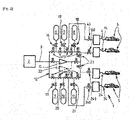
- the device 1 for filling pressurized gas tanks (service station for example) shown in [ Fig. 1 ] comprises a source 2 of gas, a transfer circuit 3 comprising at least one upstream end connected to the source 2 and several downstream ends 4 intended to be removably connected with respective reservoirs 5 to be filled.
- the source 2 can comprise one or more pressurized gas reservoirs and/or one or more liquefied gas storages (associated or not with a vaporization system), one or more electrolysers and/or any other appropriate pressurized gas source.
- the transfer circuit 3 comprises, between its upstream and downstream ends, a portion of pipe(s) forming a loop 12. That is to say that the loop 12 is formed by one or more pipe sections allowing circulation of the gas under pressure in one direction (or in the opposite direction) between two elements connected to separate places of the loop 12. For example, theoretically the gas can pass through the loop and return to the starting point by circulating in one direction or in the opposite direction.
- Circuit 3 comprises a set of buffer storage(s) 6 to 11 connected in parallel to the transfer circuit (3) via a set of valve(s) 16 to 21 for respective connection. More precisely, the buffer storage(s) 6 to 11 are connected in parallel to said loop 12. That is to say that each of the buffer storages (six in this example) can be fluidically connected with the other storages buffers via loop 12 (with gas flow in either direction through loop 12).
- each of the downstream ends comprises a valve 14, 140, 240 of respective connection.
- connection valves 16 to 21 and the connection valves 14, 140, 240 allows, via the loop 12, the fluidic connection (or not) of each buffer storage with each of the first ends 4 downstream.
- this same control of the valves allows the fluidic connection, via the loop (12), of at least a first buffer storage with a first downstream end and, simultaneously, the fluidic connection, via the loop (12 ) of at least one second buffer storage with a second downstream end and/or the fluidic connection of two separate buffer storages.
- this architecture makes it possible to fill several reservoirs 5 at the same time from different respective buffer storages. Likewise, this allows, where applicable, the simultaneous filling of one or more buffer storages.
- the loop 12 of the transfer circuit 3 thus preferably comprises a set of isolation valves 13 configured, according to their closing/opening state, to block or authorize the circulation of the fluid in the loop 12 towards or from a buffer storage by controlling the direction of circulation in the loop 12.
- the set of isolation valves 13 comprises, for each buffer storage, two valves 13 arranged respectively on either side of the connection of the buffer storage with the loop 12.
- the set of isolation valves 13 comprises, for each buffer storage, two valves 13 arranged respectively on either side of the connection of the buffer storage with the loop 12.
- the loop 12 preferably comprises a valve 23 located between two adjacent connections of downstream ends 4 to the loop 12.
- this valve 23 makes it possible to supply the downstream end or ends 4 located on one side of this valve (via a portion of the loop with gas circulation in a first direction of circulation) and, simultaneously, to supply the downstream end(s) 4 located on the other side of this valve 23 (via another portion of the loop 12 with gas circulation in a direction opposite to the first direction of circulation).
- Circuit 3 may advantageously include at least one compressor 15 arranged in series between source 2 and loop 12. As can be seen in [ Fig. 1 ], the circuit may in particular comprise a set of two compressors 15, 22 (or more) connected in parallel between the source 2 and the loop 12.
- the compressor 15 thus comprises a gas inlet to be compressed connected to the source 2 and a compressed gas outlet connected to the loop 12 (and therefore to the buffer storages and to the downstream ends 4 of the circuit).
- the embodiment of the [ Fig. 2 ] differs from that of the [ Fig. 1 ] essentially in that the compressor or compressors 15, 22 are arranged "in the middle" of the loop 12. That is to say that the input of the compressor 15, 22 is connected to a portion of the loop 12 and the outlet of the compressor 15, 22 is connected to another portion of the loop 12.
- This configuration makes it possible on the one hand to supply the inlet of the compressor 15, 22 with fluid coming from the source 2 and/or from any which one(s) of the buffer storages and, on the other hand, to supply compressed gas by the compressor 15, 22 all or part of the other buffer storages and/or the downstream ends 4 of the circuit.
- the device according to the invention thus makes it possible to supply gas under pressure to one or more reservoirs 5 with any buffer storage(s) (for example with the buffer storages having the highest pressure) and, at the same time, to (re)fill the buffer storages (via for example the compressor 15).
- one, two or three buffer storages 6, 7, 8 can be used for filling a first reservoir 5 while, during this time, one, two or all of the other buffer storages 9, 10, 11 are filled by the compressor 15.
- two or more tanks 5 can be filled respectively by two respective sets of buffer storage(s) while, at the same time, a third set of buffer storage(s) is filled by compressor 15.
- the device makes it possible to carry out several cascades/simultaneous fillings of several reservoirs 5.
- This flexible modular pooling enables a cost reduction of around 50%.
- This solution also allows an optimization of the electrical consumption of the compressor 15 because the latter can use high pressure sources (buffer storages case of the [ Fig. 2 ]) which reduces its power consumption and increases its throughput.
- All or part of the elements can be controlled and controlled by an electronic data storage and processing control unit comprising, for example, a microprocessor and in particular a computer.
- an electronic data storage and processing control unit comprising, for example, a microprocessor and in particular a computer.
- the flow rate and/or the pressure of the gas transferred into the reservoirs 5 can in particular be controlled to follow a rise in pressure/temperature/density or other (pre)determined.
- the loop can be devoid of a compressor.
Landscapes
- Engineering & Computer Science (AREA)
- Mechanical Engineering (AREA)
- General Engineering & Computer Science (AREA)
- Filling Or Discharging Of Gas Storage Vessels (AREA)
Description
- L'invention concerne un dispositif et procédé de remplissage de réservoirs de gaz sous pression.
- L'invention concerne plus particulièrement un dispositif de remplissage de réservoirs de gaz sous pression, notamment de réservoirs d'hydrogène gazeux de véhicules automobiles, le dispositif comprenant au moins une source de gaz, un circuit de transfert comprenant au moins une extrémité amont reliée à la source et au moins une extrémité aval destinée à être raccordée de façon amovible avec un réservoir à remplir, le circuit de transfert comprenant en outre, entre ses extrémités amont et aval, un ensemble de stockage(s) tampon(s) raccordé(s) en parallèle au circuit de transfert via un ensemble de vanne(s) de raccordement respectives, le circuit de transfert comprenant une portion de conduite(s) formant une boucle, une pluralité des stockage(s) tampon(s) étant reliées en parallèle à ladite boucle.
- Il est connu de remplir des réservoirs de gaz sous pression par équilibrage ou cascade (avec un ou des stockages tampons) et/ou par compression direct ou indirecte (cf. par exemple
US2017336028A1 ,JP20031742497 FR2891347A - Dans la plupart des dispositifs connus, le remplissage des stockages tampon utilisés pour le remplissage n'est possible qu'après le remplissage du réservoir.
- De plus, des dispositifs connus permettent le remplissage simultané de plusieurs réservoirs mais pour des réservoirs ayant les mêmes conditions de pression initiale. Le remplissage simultané de plusieurs réservoirs ayant des conditions de pressions initiales différentes n'est possible qu'au prix d'une installation lourde et coûteuse (sources de pression dédiées pour chaque ligne de remplissage).
- Un but de la présente invention est de pallier tout ou partie des inconvénients de l'art antérieur relevés ci-dessus.
- A cette fin, le dispositif selon l'invention, par ailleurs conforme à la définition générique qu'en donne le préambule ci-dessus, est essentiellement caractérisé en ce que le circuit de transfert comprend une pluralité d'extrémités aval distinctes destinée chacune à être raccordée de façon amovible avec un réservoir respectif à remplir, lesdites extrémités aval étant raccordées en parallèle à ladite boucle et comportant un ensemble de vanne(s) de liaison respectives, de sorte que le contrôle des vannes de raccordement et des vannes de liaison permet la mise en relation fluidique, via la boucle, d'au moins un premier stockage tampon avec une première extrémité aval et, simultanément, la mise en relation fluidique, via la boucle, d'au moins un second stockage tampon avec une seconde extrémité aval et/ou la mise en relation fluidique de deux stockages tampons distincts.
- Par ailleurs, des modes de réalisation de l'invention peuvent comporter l'une ou plusieurs des caractéristiques suivantes :
- la boucle du circuit de transfert comprend un ensemble de vannes d'isolation configurées, selon leur état de fermeture/ouverture, pour bloquer ou autoriser la circulation du fluide dans la boucle vers ou depuis un stockage tampon en contrôlant le sens de circulation dans la boucle
- l'ensemble de vannes d'isolation comprend, pour chaque stockage tampon, deux vannes disposées respectivement de part et d'autre de la liaison du stockage tampon avec la boucle,
- la boucle comprend au moins une vanne située entre deux raccordements adjacents d'extrémités aval à la boucle,
- le circuit de transfert comprend au moins un compresseur comportant une entrée de gaz à comprimer raccordée à l'un au moins parmi : la source, au moins un stockage tampon, et une sortie de gaz comprimée raccordée à au moins l'un parmi : au moins un stockage tampon, au moins l'une des pluralité d'extrémités aval du circuit,
- le dispositif comprend au moins un compresseur disposé en série dans le circuit entre la source et la boucle, c'est-à-dire que l'entrée du compresseur est reliée à la source et la sortie du compresseur est raccordée à la boucle pour permettre d'alimenter en gaz comprimé tout ou partie du ou des stockages tampons et/ou des extrémités aval du circuit via la boucle,
- le dispositif comprend au moins un compresseur disposé dans le circuit, l'entrée du compresseur étant raccordée à une portion de la boucle et la sortie du compresseur étant raccordée à une autre portion de la boucle, pour permettre d'alimenter l'entrée du compresseur avec du fluide provenant de la source et/ou d'au moins un stockage tampon et pour permettre d'alimenter en gaz comprimé par le compresseur tout ou partie des autres stockages tampon et/ou des extrémités aval du circuit via la boucle,
- le dispositif comprend deux compresseurs disposés en parallèle ou en série dans le circuit de transfert,
- L'invention concerne également un procédé de remplissage de réservoirs de gaz sous pression, notamment de réservoirs d'hydrogène gazeux de véhicules automobiles, utilisant un dispositif selon l'une quelconque des caractéristiques précédentes ou ci-après, le procédé comportant une étape de transfert de gaz sous pression dans un premier réservoir raccordé à une première extrémité aval du circuit de transfert via une première portion de la boucle.
- Selon d'autres particularités possibles :
- le procédé comporte, simultanément à l'étape de transfert de gaz sous pression dans le premier réservoir, une étape de transfert de gaz sous pression dans un second réservoir raccordé à une seconde extrémité aval du circuit de transfert via une seconde portion de la boucle,
- lors de l'étape de transfert de gaz sous pression dans le second réservoir, le gaz sous pression est fourni par au moins un stockage tampon, notamment plusieurs stockages tampons utilisés successivement en cascade et/ou par un compresseur
- le procédé comporte, simultanément à l'étape de transfert de gaz sous pression dans le premier réservoir, une étape de transfert de gaz sous pression dans au moins un stockage tampon via une autre portion de la boucle
- lors de l'étape de transfert de gaz sous pression dans au moins un stockage tampon, le gaz sous pression est fourni par au moins un stockage tampon, notamment plusieurs stockages tampons utilisés successivement en cascade et/ou par un compresseur,
- lors de l'étape de transfert de gaz sous pression dans le premier réservoir le gaz sous pression est fourni par au moins un stockage tampon, notamment plusieurs stockages tampons utilisés successivement en cascade et/ou par un compresseur
- L'invention peut concerner également tout dispositif ou procédé alternatif comprenant toute combinaison des caractéristiques ci-dessus ou ci-dessous dans le cadre des revendications.
- D'autres particularités et avantages apparaîtront à la lecture de la description ci-après, faite en référence aux figures dans lesquelles :
- [
Fig. 1 ] représente une vue schématique et partielle illustrant la structure et le fonctionnement d'un premier exemple de réalisation d'un dispositif selon l'invention, - [
Fig. 2 ] représente une vue schématique et partielle illustrant la structure et le fonctionnement d'un deuxième exemple de réalisation d'un dispositif selon l'invention. - Le dispositif 1 de remplissage de réservoirs de gaz sous pression (station-service par exemple) représenté à la [
Fig. 1 ] comprend une source 2 de gaz, un circuit 3 de transfert comprenant au moins une extrémité amont reliée à la source 2 et plusieurs extrémités aval 4 destinées à être raccordées de façon amovible avec des réservoirs 5 respectifs à remplir. - La source 2 peut comprendre un ou des réservoirs de gaz sous pression et/ou un ou des stockages de gaz liquéfié (associés ou non à un système de vaporisation), un ou des électrolyseurs et/ou tout autre source de gaz sous pression appropriée.
- Le circuit 3 de transfert comprend, entre ses extrémités amont et aval, une portion de conduite(s) formant une boucle 12. C'est-à-dire que la boucle 12 est formée par un ou plusieurs tronçons de conduites permettant une circulation du gaz sous pression dans un sens (ou dans le sens contraire) entre deux éléments raccordés à des endroits distincts de la boucle 12. Par exemple, théoriquement le gaz peut transiter dans la boucle et revenir au point de départ en circulant dans un sens ou dans le sens opposé.
- Le circuit 3 comprend un ensemble de stockage(s) tampon(s) 6 à 11 raccordé(s) en parallèle au circuit (3) de transfert via un ensemble de vanne(s) 16 à 21 de raccordement respectives. Plus précisément, les stockage(s) tampon(s) 6 à 11 sont raccordés en parallèle à ladite boucle 12. C'est-à-dire que chacun des stockage tampons (six dans cet exemple) peut être relié fluidiquement avec les autres stockages tampons via la boucle 12 (avec un flux de gaz dans un sens ou dans l'autre dans la boucle 12) .
- De même, les extrémités aval 4 (trois dans cet exemple) du circuit 3 sont raccordées en parallèle à ladite boucle 12. De préférence, chacune des extrémités aval comprend une vanne 14, 140, 240 de liaison respective.
- Ainsi, le contrôle des vannes de raccordement 16 à 21 et des vannes de liaison 14, 140, 240 permet, via la boucle 12, la mise en relation fluidique (ou non) de chaque stockage tampon avec chacune des premières extrémités 4 aval. De même, ce même contrôle des vannes permet la mise en relation fluidique, via la boucle (12), d'au moins un premier stockage tampon avec une première extrémité aval et, simultanément, la mise en relation fluidique, via la boucle (12) d'au moins un second stockage tampon avec une seconde extrémité aval et/ou la mise en relation fluidique de deux stockages tampons distincts.
- C'est-à-dire que cette architecture permet de remplir plusieurs réservoirs 5 en même temps à partir de stockages tampons respectifs différents. De même, ceci permet le cas échant simultanément le remplissage d'un ou plusieurs stockages tampons.
- La boucle 12 du circuit 3 de transfert comprend ainsi de préférence un ensemble de vannes 13 d'isolation configurées, selon leur état de fermeture/ouverture, pour bloquer ou autoriser la circulation du fluide dans la boucle 12 vers ou depuis un stockage tampon en contrôlant le sens de circulation dans la boucle 12.
- Par exemple, l'ensemble de vannes 13 d'isolation comprend, pour chaque stockage tampon, deux vannes 13 disposées respectivement de part et d'autre de la liaison du stockage tampon avec la boucle 12. Ainsi, en fermant ces deux vannes 13 l'accès au stockage tampon est fermé. En cas d'ouverture de l'un des deux vannes la circulation de fluide est possible entre la boucle 12 et le stockage tampon du côté de la vanne ouverte sans affecter le stockage tampon adjacent situé après l'autre vanne qui est fermée.
- De même, comme illustré à la [
Fig. 1 ], la boucle 12 comprend de préférence une vanne 23 située entre deux raccordements adjacents d'extrémités aval 4 à la boucle 12. En position fermée, cette vanne 23 permet d'alimenter la ou les extrémités aval 4 situées d'un côté de cette vanne (via une portion de la boucle avec circulation du gaz dans un premier sens de circulation) et, simultanément, d'alimenter la ou les extrémités aval 4 située de l'autre côté de cette vanne 23 (via une autre portion de la boucle 12 avec circulation du gaz dans un sens opposé au premier sens de circulation). - Le circuit 3 peut comporter avantageusement au moins un compresseur 15 disposé en série entre la source 2 et la boucle 12. Comme visible à la [
Fig. 1 ], le circuit peut notamment comporter un ensemble de deux compresseurs 15, 22 (ou plus) montés en parallèle entre la source 2 et la boucle 12. - Le compresseurs 15 comprend ainsi une entrée de gaz à comprimer raccordée à la source 2 et une sortie de gaz comprimée raccordée à la boucle 12 (et donc aux stockages tampons et aux extrémités aval 4 du circuit).
- Ainsi, en contrôlant l'ouverture des vannes appropriées il est possible de remplir un ou des stockages tampons et/ou d'alimenter une ou des extrémités aval 4 avec le compresseur 15 pendant par exemple que d'autres stockages tampons sont utilisés pour remplir d'autre(s) réservoir(s) 5.
- Le mode de réalisation de la [
Fig. 2 ] se distingue de celui de la [Fig. 1 ] essentiellement en ce que le ou les compresseurs 15, 22 sont disposés « au milieu » de la boucle 12. C'est-à-dire que l'entrée du compresseur 15, 22 est raccordée à une portion de la boucle 12 et la sortie du compresseur 15, 22 est raccordée à une autre portion de la boucle 12. Cette configuration permet d'une part d'alimenter l'entrée du compresseur 15, 22 avec du fluide provenant de la source 2 et/ou de n'importe le(s)quel(s) des stockages tampons et, d'autre part, d'alimenter en gaz comprimé par le compresseur 15, 22 tout ou partie des autres stockages tampons et/ou des extrémités aval 4 du circuit. - Le dispositif selon l'invention permet ainsi d'alimenter en gaz sous pression un ou plusieurs réservoirs 5 avec n'importe quel(s) stockage(s) tampon(s) (par exemple avec les stockages tampons ayant la pression la plus élevée) et, en même temps, de (re)remplir les stockages tampons (via par exemple le compresseur 15).
- Ainsi, un, deux ou trois stockages 6, 7, 8 tampons peuvent être utilisés pour le remplissage d'un premier réservoir 5 tandis que, pendant ce temps, un, deux ou tous les autres stockages tampons 9, 10, 11 sont remplis par le compresseur 15. De même, simultanément deux réservoirs 5 ou plus peuvent être remplis respectivement par deux ensembles respectifs de stockage(s) tampon(s) tandis que, en même temps, un troisième ensemble de stockage(s) tampon(s) est rempli par le compresseur 15.
- Ainsi, bien que de structure simple et peu coûteuse, le dispositif permet de réaliser plusieurs cascades/remplissages simultanés de plusieurs réservoirs 5.
- Ceci permet d'optimiser les temps de remplissage et de repressurisation de l'installation.
- Cette solution permet également de diminuer le nombre de stockages tampons nécessaires par flexible de remplissage (extrémité aval 4).
- En effet, au lieu d'utiliser par exemple trois stockages tampons (400 litres et 900bar) pour chaque extrémité 4 aval (« dispenser » en anglais), six de ces stockages tampons pourraient être suffisants pour alimenter trois extrémités aval 4 (c'est-à-dire trois flexibles de remplissages de réservoirs 5).
- Cette mutualisation modulaire flexible permet une réduction des coûts de l'ordre de 50%.
- Cette solution permet également une optimisation des consommations électrique du compresseur 15 car ce dernier peut utiliser des sources à haute pression (stockages tampon cas de la [
Fig. 2 ]) qui réduit sa consommation électrique et augmente son débit. - Ainsi l'installation est plus souvent disponible pour des remplissages car le temps nécessaire au remplissage des stockages tampons entre deux utilisations est diminué.
- Tout ou partie des éléments (vannes, compresseur...) peuvent être contrôlés et pilotés par un organe de commande électronique de stockage et de traitement de données comprenant par exemple un microprocesseur et notamment un ordinateur. Classiquement, le débit et/ou la pression du gaz transféré dans les réservoirs 5 peut notamment être contrôlé pour suivre une montée en pression/température/densité ou autre (pré)déterminée.
- Comme illustré, la boucle peut être dépourvue de compresseur.
Claims (14)
- Dispositif de remplissage de réservoirs de gaz sous pression, notamment de réservoirs d'hydrogène gazeux de véhicules automobiles, le dispositif comprenant au moins une source (2) de gaz, un circuit (3) de transfert comprenant au moins une extrémité amont reliée à la source (2) et au moins une extrémité aval (4) destinée à être raccordée de façon amovible avec un réservoir (5) à remplir, le circuit (3) de transfert comprenant en outre, entre ses extrémités amont et aval, un ensemble de stockage(s) tampons (6 à 11) raccordé(s) en parallèle au circuit (3) de transfert via un ensemble de vanne(s) (16 à 21) de raccordement respectives, le circuit (3) de transfert comprenant une portion de conduite (s) formant une boucle (12), une pluralité des stockage(s) tampon (6 à 11) étant reliées en parallèle à ladite boucle (12), caractérisé en ce que le circuit (3) de transfert comprend une pluralité d'extrémités aval (4) distinctes destinée chacune à être raccordée de façon amovible avec un réservoir (5) respectif à remplir, lesdites extrémités aval (4) étant raccordées en parallèle à ladite boucle (12) et comportant un ensemble de vanne(s) (40, 140, 240, 340) de liaison respectives, de sorte que le contrôle des vannes de raccordement et des vannes de liaison permet la mise en relation fluidique, via la boucle (12), d'au moins un premier stockage tampon avec une première extrémité aval et, simultanément, la mise en relation fluidique, via la boucle (12), d'au moins un second stockage tampon avec une seconde extrémité aval et/ou la mise en relation fluidique de deux stockages tampons distincts.
- Dispositif selon la revendication 1, caractérisé en ce que la boucle (12) du circuit (3) de transfert comprend un ensemble de vannes (13) d'isolation configurées, selon leur état de fermeture/ouverture, pour bloquer ou autoriser la circulation du fluide dans la boucle (12) vers ou depuis un stockage tampon en contrôlant le sens de circulation dans la boucle (12).
- Dispositif selon la revendication 2, caractérisé en ce que l'ensemble de vannes (13) d'isolation comprend, pour chaque stockage tampon, deux vannes disposées respectivement de part et d'autre de la liaison du stockage tampon avec la boucle (12).
- Dispositif selon l'une quelconque des revendications 1 à 3, caractérisé en ce que la boucle (12) comprend au moins une vanne (13, 23) située entre deux raccordements adjacents d'extrémités aval (4) à la boucle (12).
- Dispositif selon l'une quelconque des revendications 1 à 4, caractérisé en ce que le circuit (3) de transfert comprend au moins un compresseur (15, 22) comportant une entrée de gaz à comprimer raccordée à l'un au moins parmi : la source (2), au moins un stockage tampon, et une sortie de gaz comprimée raccordée à au moins l'un parmi : au moins un stockage tampon, au moins l'une des pluralité d'extrémités aval (4) du circuit (3).
- Dispositif selon la revendication 5, caractérisé en ce qu'il comprend au moins un compresseur (15, 22) disposé en série dans le circuit entre la source (2) et la boucle (12), c'est-à-dire que l'entrée du compresseur (15, 22) est reliée à la source (2) et la sortie du compresseur (15, 22) est raccordée à la boucle (12) pour permettre d'alimenter en gaz comprimé tout ou partie des stockage tampon et/ou des extrémités aval (4) du circuit via la boucle (12).
- Dispositif selon la revendication 5, caractérisé en ce qu'il comprend au moins un compresseur (15, 22) disposé dans le circuit (3), l'entrée du compresseur (15, 22) étant raccordée à une portion de la boucle (12) et la sortie du compresseur (15, 22) étant raccordée à une autre portion de la boucle (12), pour permettre d'alimenter l'entrée du compresseur (15, 22) avec du fluide provenant de la source (2) et/ou d'au moins un stockage tampon et pour permettre d'alimenter en gaz comprimé par le compresseur (15, 22) tout ou partie des autres stockages tampon et/ou des extrémités aval (4) du circuit via la boucle (12).
- Dispositif selon l'une quelconque des revendications 5 à 7, caractérisé en ce qu'il comprend deux compresseurs (15, 22) disposés en parallèle ou en série dans le circuit (3) de transfert.
- Procédé de remplissage de réservoirs de gaz sous pression, notamment de réservoirs d'hydrogène gazeux de véhicules automobiles, utilisant un dispositif selon l'une quelconque des revendications précédentes, le procédé comportant une étape de transfert de gaz sous pression dans un premier réservoir (5) raccordé à une première extrémité aval (4) du circuit (3) de transfert via une première portion de la boucle (12).
- Procédé selon la revendication 9, caractérisé en ce qu'il comporte, simultanément à l'étape de transfert de gaz sous pression dans le premier réservoir (5), une étape de transfert de gaz sous pression dans un second réservoir (5) raccordé à une seconde extrémité aval (4) du circuit (3) de transfert via une seconde portion de la boucle (12).
- Procédé selon la revendication 10, caractérisé en ce que lors de l'étape de transfert de gaz sous pression dans le second réservoir (5), le gaz sous pression est fourni par au moins un stockage tampon, notamment plusieurs stockages tampon utilisés successivement en cascade et/ou par un compresseur (15, 22).
- Procédé selon l'une quelconque des revendications 9 à 11, caractérisé en ce qu'il comporte, simultanément à l'étape de transfert de gaz sous pression dans le premier réservoir (5), une étape de transfert de gaz sous pression dans au moins un stockage tampon via une autre portion de la boucle (12).
- Procédé selon la revendication 12, caractérisé en ce que, lors de l'étape de transfert de gaz sous pression dans au moins un stockage tampon, le gaz sous pression est fourni par au moins un stockage tampon, notamment plusieurs stockages tampon utilisés successivement en cascade et/ou par un compresseur (15, 22).
- Procédé selon l'une quelconque des revendications 9 à 13, caractérisé en ce que, lors de l'étape de transfert de gaz sous pression dans le premier réservoir (5) le gaz sous pression est fourni par au moins un stockage tampon, notamment plusieurs stockages tampon utilisés successivement en cascade et/ou par un compresseur (15, 22).
Applications Claiming Priority (1)
| Application Number | Priority Date | Filing Date | Title |
|---|---|---|---|
| FR1900192A FR3091572B1 (fr) | 2019-01-09 | 2019-01-09 | Dispositif et procédé de remplissage de réservoirs de gaz sous pression |
Publications (2)
| Publication Number | Publication Date |
|---|---|
| EP3680543A1 EP3680543A1 (fr) | 2020-07-15 |
| EP3680543B1 true EP3680543B1 (fr) | 2022-05-04 |
Family
ID=66867366
Family Applications (1)
| Application Number | Title | Priority Date | Filing Date |
|---|---|---|---|
| EP19215506.7A Active EP3680543B1 (fr) | 2019-01-09 | 2019-12-12 | Dispositif et procédé de remplissage de réservoirs de gaz sous pression |
Country Status (7)
| Country | Link |
|---|---|
| US (1) | US11530782B2 (fr) |
| EP (1) | EP3680543B1 (fr) |
| JP (1) | JP7532037B2 (fr) |
| KR (1) | KR102824426B1 (fr) |
| CN (1) | CN111425756B (fr) |
| DK (1) | DK3680543T3 (fr) |
| FR (1) | FR3091572B1 (fr) |
Families Citing this family (13)
| Publication number | Priority date | Publication date | Assignee | Title |
|---|---|---|---|---|
| DK180560B1 (en) * | 2019-01-18 | 2021-06-23 | Nel Hydrogen As | Large-scale hydrogen refueling station |
| FR3115347B1 (fr) * | 2020-10-16 | 2022-10-07 | Air Liquide | Dispositif et procédé de remplissage de réservoirs de gaz sous pression |
| KR102904037B1 (ko) * | 2021-03-03 | 2025-12-24 | 에네오스 가부시키가이샤 | 가스 충전 장치 |
| FR3122239B1 (fr) * | 2021-04-23 | 2023-12-08 | Faurecia Systemes Dechappement | Réservoir de gaz sous pression comprenant au moins deux bonbonnes connectées par un rail |
| FR3123708B1 (fr) * | 2021-06-08 | 2024-03-08 | Absolut System | Système de stockage d’hydrogène liquide et de distribution d’hydrogène gazeux sous pression |
| FR3125322B1 (fr) * | 2021-07-19 | 2023-06-09 | Air Liquide | Installation et procédé de distribution d'hydrogène liquéfié |
| DK202270049A1 (en) * | 2022-02-04 | 2023-11-06 | Everfuel Europe As | Synchronous refueling of a plurality of fuel cell vehicles from a mobile refueling station |
| CN114484268B (zh) * | 2022-02-23 | 2022-11-01 | 西南化工研究设计院有限公司 | 一种氢气压缩充装管束车系统及其充装方法 |
| US20230278394A1 (en) * | 2022-03-01 | 2023-09-07 | Carrier Corporation | Modules for transport refrigeration system |
| EP4517153A1 (fr) * | 2023-08-28 | 2025-03-05 | Linde GmbH | Procédé et installation pour le ravitaillement simultané d'une pluralité de véhicules avec de l'hydrogène |
| CN117739274A (zh) * | 2023-12-04 | 2024-03-22 | 东风柳州汽车有限公司 | 一种多气瓶并联式cng管路系统 |
| FR3158773B1 (fr) * | 2024-01-31 | 2025-12-26 | Faurecia Hydrogen Solutions France | Collecteur hydraulique |
| JP2025139185A (ja) * | 2024-03-12 | 2025-09-26 | トヨタ自動車株式会社 | ガスタンクの交換方法 |
Family Cites Families (12)
| Publication number | Priority date | Publication date | Assignee | Title |
|---|---|---|---|---|
| US5673735A (en) * | 1995-02-07 | 1997-10-07 | Aurora Technology Corporation | Process for storing and delivering gas |
| JP2003172497A (ja) | 2001-12-05 | 2003-06-20 | Koatsu Gas Kogyo Co Ltd | 自動車用天然ガス充填設備 |
| FR2891347B1 (fr) * | 2005-09-28 | 2007-11-02 | Air Liquide | Procede et dispositif de remplissage d'un gaz sous pression dans un reservoir |
| JP4795825B2 (ja) * | 2006-03-24 | 2011-10-19 | 大陽日酸株式会社 | ガス供給装置およびガス供給方法 |
| US9618158B2 (en) * | 2011-05-02 | 2017-04-11 | New Gas Industries, L.L.C. | Method and apparatus for compressing gas in a plurality of stages to a storage tank array having a plurality of storage tanks |
| CA2912650A1 (fr) * | 2013-05-31 | 2014-12-04 | Nuvera Fuel Cells, Inc. | Procede et systeme en cascade pour reapprovisionnement en hydrogene distribue |
| FR3008473B1 (fr) * | 2013-07-11 | 2015-07-17 | Air Liquide | Procede et station de remplissage de gaz |
| FR3033866B1 (fr) * | 2015-03-17 | 2017-03-10 | Air Liquide | Procede et dispositif de remplissage de reservoirs |
| US10240721B2 (en) * | 2015-10-08 | 2019-03-26 | Oneh2, Inc. | Method, apparatus, and system for refueling hydrogen vehicles |
| EP3249281B1 (fr) * | 2016-05-23 | 2022-02-23 | Air Products And Chemicals, Inc. | Distribution de gaz comprimé |
| JP2018084329A (ja) * | 2016-11-11 | 2018-05-31 | Jxtgエネルギー株式会社 | 水素燃料の供給方法及び水素供給システム |
| FR3067094B1 (fr) | 2017-06-01 | 2020-08-14 | L'air Liquide Sa Pour L'etude Et L'exploitation Des Procedes Georges Claude | Robinet, stockage et station de remplissage |
-
2019
- 2019-01-09 FR FR1900192A patent/FR3091572B1/fr not_active Expired - Fee Related
- 2019-12-12 EP EP19215506.7A patent/EP3680543B1/fr active Active
- 2019-12-12 DK DK19215506.7T patent/DK3680543T3/da active
-
2020
- 2020-01-06 KR KR1020200001258A patent/KR102824426B1/ko active Active
- 2020-01-08 CN CN202010017321.8A patent/CN111425756B/zh active Active
- 2020-01-08 JP JP2020001589A patent/JP7532037B2/ja active Active
- 2020-01-09 US US16/738,605 patent/US11530782B2/en active Active
Also Published As
| Publication number | Publication date |
|---|---|
| EP3680543A1 (fr) | 2020-07-15 |
| FR3091572A1 (fr) | 2020-07-10 |
| FR3091572B1 (fr) | 2020-12-11 |
| JP2020112266A (ja) | 2020-07-27 |
| US11530782B2 (en) | 2022-12-20 |
| KR20200086634A (ko) | 2020-07-17 |
| US20200217456A1 (en) | 2020-07-09 |
| JP7532037B2 (ja) | 2024-08-13 |
| DK3680543T3 (da) | 2022-07-25 |
| KR102824426B1 (ko) | 2025-06-25 |
| CN111425756B (zh) | 2023-03-10 |
| CN111425756A (zh) | 2020-07-17 |
Similar Documents
| Publication | Publication Date | Title |
|---|---|---|
| EP3680543B1 (fr) | Dispositif et procédé de remplissage de réservoirs de gaz sous pression | |
| EP3985299B1 (fr) | Dispositif et procédé de remplissage de réservoirs de gaz sous pression | |
| EP1779026B1 (fr) | Systeme de stockage de gaz, procede de mise en oeuvre et vehicule incorporant un tel systeme | |
| EP2174057B1 (fr) | Proceeé de remplissage d'un gaz sous pression dans un reservoir | |
| EP3628911A1 (fr) | Dispositif et procédé de remplissage de réservoirs de gaz sous pression | |
| EP4090880B1 (fr) | Installation et un procédé de stockage et de distribution de fluide cryogénique | |
| EP3892910B1 (fr) | Dispositif de remplissage de réservoirs de gaz sous pression | |
| US10145512B2 (en) | Compressed natural gas storage and dispensing system | |
| US9951905B2 (en) | Compressed natural gas storage and dispensing system | |
| EP3892911B1 (fr) | Dispositif et procédé de remplissage de réservoirs de gaz sous pression | |
| FR3069237B1 (fr) | Dispositif de production et de distribution d'azote, en particulier pour un navire de transport de gaz liquefie | |
| FR2590187A1 (fr) | Systeme de circulation et d'injection a boucle | |
| FR2557643A1 (fr) | Dispositif d'alimentation d'une pompe de fluide diphasique et installation de production d'hydrocarbures comportant un tel dispositif | |
| FR3079006A1 (fr) | Station de remplissage de reservoir(s) de gaz sous pression et procede d'augmentation de son autonomie | |
| CA2360885C (fr) | Circuit economiseur de debit de carburant | |
| EP4133206B1 (fr) | Dispositif et procédé de remplissage de réservoirs de gaz sous pression | |
| WO2019002724A1 (fr) | Station et procédé de remplissage de réservoirs de gaz sous pression | |
| FR2973858A1 (fr) | Procede et station de remplissage d'un reservoir | |
| FR2564944A1 (fr) | Perfectionnements apportes a ou concernant des systemes distributeurs pour recipients de gaz. | |
| FR2958368A1 (fr) | Dispositif de distribution de gaz et installation comportant un tel dispositif | |
| JP4589795B2 (ja) | 液化ガス充填装置 | |
| EP4416432B1 (fr) | Perfectionnement apporté à un dispositif et à un procédé associé pour économiser l'énergie calorifique et l'eau dans une installation sanitaire | |
| FR2601962A1 (fr) | Dispositif de conservation et de distribution, notamment de vin, dans des bouteilles couchees. | |
| FR2638052A1 (fr) | Appareil de traitement de cereales et d'installations contenant des cereales | |
| EP0348304A2 (fr) | Valve gaz de sécurité et de régulation |
Legal Events
| Date | Code | Title | Description |
|---|---|---|---|
| PUAI | Public reference made under article 153(3) epc to a published international application that has entered the european phase |
Free format text: ORIGINAL CODE: 0009012 |
|
| STAA | Information on the status of an ep patent application or granted ep patent |
Free format text: STATUS: THE APPLICATION HAS BEEN PUBLISHED |
|
| AK | Designated contracting states |
Kind code of ref document: A1 Designated state(s): AL AT BE BG CH CY CZ DE DK EE ES FI FR GB GR HR HU IE IS IT LI LT LU LV MC MK MT NL NO PL PT RO RS SE SI SK SM TR |
|
| AX | Request for extension of the european patent |
Extension state: BA ME |
|
| STAA | Information on the status of an ep patent application or granted ep patent |
Free format text: STATUS: REQUEST FOR EXAMINATION WAS MADE |
|
| 17P | Request for examination filed |
Effective date: 20210115 |
|
| RBV | Designated contracting states (corrected) |
Designated state(s): AL AT BE BG CH CY CZ DE DK EE ES FI FR GB GR HR HU IE IS IT LI LT LU LV MC MK MT NL NO PL PT RO RS SE SI SK SM TR |
|
| GRAP | Despatch of communication of intention to grant a patent |
Free format text: ORIGINAL CODE: EPIDOSNIGR1 |
|
| STAA | Information on the status of an ep patent application or granted ep patent |
Free format text: STATUS: GRANT OF PATENT IS INTENDED |
|
| INTG | Intention to grant announced |
Effective date: 20210729 |
|
| RIN1 | Information on inventor provided before grant (corrected) |
Inventor name: FRANCOIS, THIBAUT |
|
| GRAJ | Information related to disapproval of communication of intention to grant by the applicant or resumption of examination proceedings by the epo deleted |
Free format text: ORIGINAL CODE: EPIDOSDIGR1 |
|
| STAA | Information on the status of an ep patent application or granted ep patent |
Free format text: STATUS: REQUEST FOR EXAMINATION WAS MADE |
|
| INTC | Intention to grant announced (deleted) | ||
| GRAP | Despatch of communication of intention to grant a patent |
Free format text: ORIGINAL CODE: EPIDOSNIGR1 |
|
| STAA | Information on the status of an ep patent application or granted ep patent |
Free format text: STATUS: GRANT OF PATENT IS INTENDED |
|
| INTG | Intention to grant announced |
Effective date: 20220203 |
|
| GRAS | Grant fee paid |
Free format text: ORIGINAL CODE: EPIDOSNIGR3 |
|
| GRAA | (expected) grant |
Free format text: ORIGINAL CODE: 0009210 |
|
| STAA | Information on the status of an ep patent application or granted ep patent |
Free format text: STATUS: THE PATENT HAS BEEN GRANTED |
|
| AK | Designated contracting states |
Kind code of ref document: B1 Designated state(s): AL AT BE BG CH CY CZ DE DK EE ES FI FR GB GR HR HU IE IS IT LI LT LU LV MC MK MT NL NO PL PT RO RS SE SI SK SM TR |
|
| REG | Reference to a national code |
Ref country code: GB Ref legal event code: FG4D Free format text: NOT ENGLISH |
|
| REG | Reference to a national code |
Ref country code: CH Ref legal event code: EP |
|
| REG | Reference to a national code |
Ref country code: AT Ref legal event code: REF Ref document number: 1489398 Country of ref document: AT Kind code of ref document: T Effective date: 20220515 |
|
| REG | Reference to a national code |
Ref country code: IE Ref legal event code: FG4D Free format text: LANGUAGE OF EP DOCUMENT: FRENCH Ref country code: DE Ref legal event code: R096 Ref document number: 602019014440 Country of ref document: DE |
|
| REG | Reference to a national code |
Ref country code: DK Ref legal event code: T3 Effective date: 20220720 |
|
| REG | Reference to a national code |
Ref country code: NL Ref legal event code: FP |
|
| REG | Reference to a national code |
Ref country code: NO Ref legal event code: T2 Effective date: 20220504 |
|
| REG | Reference to a national code |
Ref country code: LT Ref legal event code: MG9D |
|
| REG | Reference to a national code |
Ref country code: AT Ref legal event code: MK05 Ref document number: 1489398 Country of ref document: AT Kind code of ref document: T Effective date: 20220504 |
|
| PG25 | Lapsed in a contracting state [announced via postgrant information from national office to epo] |
Ref country code: SE Free format text: LAPSE BECAUSE OF FAILURE TO SUBMIT A TRANSLATION OF THE DESCRIPTION OR TO PAY THE FEE WITHIN THE PRESCRIBED TIME-LIMIT Effective date: 20220504 Ref country code: PT Free format text: LAPSE BECAUSE OF FAILURE TO SUBMIT A TRANSLATION OF THE DESCRIPTION OR TO PAY THE FEE WITHIN THE PRESCRIBED TIME-LIMIT Effective date: 20220905 Ref country code: LT Free format text: LAPSE BECAUSE OF FAILURE TO SUBMIT A TRANSLATION OF THE DESCRIPTION OR TO PAY THE FEE WITHIN THE PRESCRIBED TIME-LIMIT Effective date: 20220504 Ref country code: HR Free format text: LAPSE BECAUSE OF FAILURE TO SUBMIT A TRANSLATION OF THE DESCRIPTION OR TO PAY THE FEE WITHIN THE PRESCRIBED TIME-LIMIT Effective date: 20220504 Ref country code: GR Free format text: LAPSE BECAUSE OF FAILURE TO SUBMIT A TRANSLATION OF THE DESCRIPTION OR TO PAY THE FEE WITHIN THE PRESCRIBED TIME-LIMIT Effective date: 20220805 Ref country code: FI Free format text: LAPSE BECAUSE OF FAILURE TO SUBMIT A TRANSLATION OF THE DESCRIPTION OR TO PAY THE FEE WITHIN THE PRESCRIBED TIME-LIMIT Effective date: 20220504 Ref country code: ES Free format text: LAPSE BECAUSE OF FAILURE TO SUBMIT A TRANSLATION OF THE DESCRIPTION OR TO PAY THE FEE WITHIN THE PRESCRIBED TIME-LIMIT Effective date: 20220504 Ref country code: BG Free format text: LAPSE BECAUSE OF FAILURE TO SUBMIT A TRANSLATION OF THE DESCRIPTION OR TO PAY THE FEE WITHIN THE PRESCRIBED TIME-LIMIT Effective date: 20220804 Ref country code: AT Free format text: LAPSE BECAUSE OF FAILURE TO SUBMIT A TRANSLATION OF THE DESCRIPTION OR TO PAY THE FEE WITHIN THE PRESCRIBED TIME-LIMIT Effective date: 20220504 |
|
| PG25 | Lapsed in a contracting state [announced via postgrant information from national office to epo] |
Ref country code: RS Free format text: LAPSE BECAUSE OF FAILURE TO SUBMIT A TRANSLATION OF THE DESCRIPTION OR TO PAY THE FEE WITHIN THE PRESCRIBED TIME-LIMIT Effective date: 20220504 Ref country code: PL Free format text: LAPSE BECAUSE OF FAILURE TO SUBMIT A TRANSLATION OF THE DESCRIPTION OR TO PAY THE FEE WITHIN THE PRESCRIBED TIME-LIMIT Effective date: 20220504 Ref country code: LV Free format text: LAPSE BECAUSE OF FAILURE TO SUBMIT A TRANSLATION OF THE DESCRIPTION OR TO PAY THE FEE WITHIN THE PRESCRIBED TIME-LIMIT Effective date: 20220504 Ref country code: IS Free format text: LAPSE BECAUSE OF FAILURE TO SUBMIT A TRANSLATION OF THE DESCRIPTION OR TO PAY THE FEE WITHIN THE PRESCRIBED TIME-LIMIT Effective date: 20220904 |
|
| PG25 | Lapsed in a contracting state [announced via postgrant information from national office to epo] |
Ref country code: SM Free format text: LAPSE BECAUSE OF FAILURE TO SUBMIT A TRANSLATION OF THE DESCRIPTION OR TO PAY THE FEE WITHIN THE PRESCRIBED TIME-LIMIT Effective date: 20220504 Ref country code: SK Free format text: LAPSE BECAUSE OF FAILURE TO SUBMIT A TRANSLATION OF THE DESCRIPTION OR TO PAY THE FEE WITHIN THE PRESCRIBED TIME-LIMIT Effective date: 20220504 Ref country code: RO Free format text: LAPSE BECAUSE OF FAILURE TO SUBMIT A TRANSLATION OF THE DESCRIPTION OR TO PAY THE FEE WITHIN THE PRESCRIBED TIME-LIMIT Effective date: 20220504 Ref country code: EE Free format text: LAPSE BECAUSE OF FAILURE TO SUBMIT A TRANSLATION OF THE DESCRIPTION OR TO PAY THE FEE WITHIN THE PRESCRIBED TIME-LIMIT Effective date: 20220504 Ref country code: CZ Free format text: LAPSE BECAUSE OF FAILURE TO SUBMIT A TRANSLATION OF THE DESCRIPTION OR TO PAY THE FEE WITHIN THE PRESCRIBED TIME-LIMIT Effective date: 20220504 |
|
| REG | Reference to a national code |
Ref country code: DE Ref legal event code: R097 Ref document number: 602019014440 Country of ref document: DE |
|
| PLBE | No opposition filed within time limit |
Free format text: ORIGINAL CODE: 0009261 |
|
| STAA | Information on the status of an ep patent application or granted ep patent |
Free format text: STATUS: NO OPPOSITION FILED WITHIN TIME LIMIT |
|
| PG25 | Lapsed in a contracting state [announced via postgrant information from national office to epo] |
Ref country code: AL Free format text: LAPSE BECAUSE OF FAILURE TO SUBMIT A TRANSLATION OF THE DESCRIPTION OR TO PAY THE FEE WITHIN THE PRESCRIBED TIME-LIMIT Effective date: 20220504 |
|
| 26N | No opposition filed |
Effective date: 20230207 |
|
| PG25 | Lapsed in a contracting state [announced via postgrant information from national office to epo] |
Ref country code: SI Free format text: LAPSE BECAUSE OF FAILURE TO SUBMIT A TRANSLATION OF THE DESCRIPTION OR TO PAY THE FEE WITHIN THE PRESCRIBED TIME-LIMIT Effective date: 20220504 |
|
| REG | Reference to a national code |
Ref country code: CH Ref legal event code: PL |
|
| REG | Reference to a national code |
Ref country code: BE Ref legal event code: MM Effective date: 20221231 |
|
| PG25 | Lapsed in a contracting state [announced via postgrant information from national office to epo] |
Ref country code: LU Free format text: LAPSE BECAUSE OF NON-PAYMENT OF DUE FEES Effective date: 20221212 |
|
| PG25 | Lapsed in a contracting state [announced via postgrant information from national office to epo] |
Ref country code: LI Free format text: LAPSE BECAUSE OF NON-PAYMENT OF DUE FEES Effective date: 20221231 Ref country code: IE Free format text: LAPSE BECAUSE OF NON-PAYMENT OF DUE FEES Effective date: 20221212 Ref country code: CH Free format text: LAPSE BECAUSE OF NON-PAYMENT OF DUE FEES Effective date: 20221231 |
|
| PG25 | Lapsed in a contracting state [announced via postgrant information from national office to epo] |
Ref country code: BE Free format text: LAPSE BECAUSE OF NON-PAYMENT OF DUE FEES Effective date: 20221231 |
|
| PG25 | Lapsed in a contracting state [announced via postgrant information from national office to epo] |
Ref country code: IT Free format text: LAPSE BECAUSE OF FAILURE TO SUBMIT A TRANSLATION OF THE DESCRIPTION OR TO PAY THE FEE WITHIN THE PRESCRIBED TIME-LIMIT Effective date: 20220504 |
|
| PG25 | Lapsed in a contracting state [announced via postgrant information from national office to epo] |
Ref country code: HU Free format text: LAPSE BECAUSE OF FAILURE TO SUBMIT A TRANSLATION OF THE DESCRIPTION OR TO PAY THE FEE WITHIN THE PRESCRIBED TIME-LIMIT; INVALID AB INITIO Effective date: 20191212 |
|
| PG25 | Lapsed in a contracting state [announced via postgrant information from national office to epo] |
Ref country code: CY Free format text: LAPSE BECAUSE OF FAILURE TO SUBMIT A TRANSLATION OF THE DESCRIPTION OR TO PAY THE FEE WITHIN THE PRESCRIBED TIME-LIMIT Effective date: 20220504 |
|
| PG25 | Lapsed in a contracting state [announced via postgrant information from national office to epo] |
Ref country code: MK Free format text: LAPSE BECAUSE OF FAILURE TO SUBMIT A TRANSLATION OF THE DESCRIPTION OR TO PAY THE FEE WITHIN THE PRESCRIBED TIME-LIMIT Effective date: 20220504 |
|
| PG25 | Lapsed in a contracting state [announced via postgrant information from national office to epo] |
Ref country code: MC Free format text: LAPSE BECAUSE OF FAILURE TO SUBMIT A TRANSLATION OF THE DESCRIPTION OR TO PAY THE FEE WITHIN THE PRESCRIBED TIME-LIMIT Effective date: 20220504 |
|
| PG25 | Lapsed in a contracting state [announced via postgrant information from national office to epo] |
Ref country code: MC Free format text: LAPSE BECAUSE OF FAILURE TO SUBMIT A TRANSLATION OF THE DESCRIPTION OR TO PAY THE FEE WITHIN THE PRESCRIBED TIME-LIMIT Effective date: 20220504 |
|
| PG25 | Lapsed in a contracting state [announced via postgrant information from national office to epo] |
Ref country code: MT Free format text: LAPSE BECAUSE OF FAILURE TO SUBMIT A TRANSLATION OF THE DESCRIPTION OR TO PAY THE FEE WITHIN THE PRESCRIBED TIME-LIMIT Effective date: 20220504 |
|
| PG25 | Lapsed in a contracting state [announced via postgrant information from national office to epo] |
Ref country code: BG Free format text: LAPSE BECAUSE OF FAILURE TO SUBMIT A TRANSLATION OF THE DESCRIPTION OR TO PAY THE FEE WITHIN THE PRESCRIBED TIME-LIMIT Effective date: 20220504 |
|
| PG25 | Lapsed in a contracting state [announced via postgrant information from national office to epo] |
Ref country code: BG Free format text: LAPSE BECAUSE OF FAILURE TO SUBMIT A TRANSLATION OF THE DESCRIPTION OR TO PAY THE FEE WITHIN THE PRESCRIBED TIME-LIMIT Effective date: 20220504 |
|
| PGFP | Annual fee paid to national office [announced via postgrant information from national office to epo] |
Ref country code: NO Payment date: 20241227 Year of fee payment: 6 |
|
| PGFP | Annual fee paid to national office [announced via postgrant information from national office to epo] |
Ref country code: GB Payment date: 20241226 Year of fee payment: 6 |
|
| PG25 | Lapsed in a contracting state [announced via postgrant information from national office to epo] |
Ref country code: TR Free format text: LAPSE BECAUSE OF FAILURE TO SUBMIT A TRANSLATION OF THE DESCRIPTION OR TO PAY THE FEE WITHIN THE PRESCRIBED TIME-LIMIT Effective date: 20220504 |
|
| PGFP | Annual fee paid to national office [announced via postgrant information from national office to epo] |
Ref country code: DE Payment date: 20251211 Year of fee payment: 7 |
|
| PGFP | Annual fee paid to national office [announced via postgrant information from national office to epo] |
Ref country code: DK Payment date: 20251224 Year of fee payment: 7 |
|
| PGFP | Annual fee paid to national office [announced via postgrant information from national office to epo] |
Ref country code: FR Payment date: 20251229 Year of fee payment: 7 Ref country code: NL Payment date: 20251219 Year of fee payment: 7 |