EP3680512A1 - Damper device - Google Patents
Damper device Download PDFInfo
- Publication number
- EP3680512A1 EP3680512A1 EP20151113.6A EP20151113A EP3680512A1 EP 3680512 A1 EP3680512 A1 EP 3680512A1 EP 20151113 A EP20151113 A EP 20151113A EP 3680512 A1 EP3680512 A1 EP 3680512A1
- Authority
- EP
- European Patent Office
- Prior art keywords
- elastic body
- damper device
- hub
- intermediate member
- disc plate
- Prior art date
- Legal status (The legal status is an assumption and is not a legal conclusion. Google has not performed a legal analysis and makes no representation as to the accuracy of the status listed.)
- Granted
Links
Images





Classifications
-
- F—MECHANICAL ENGINEERING; LIGHTING; HEATING; WEAPONS; BLASTING
- F16—ENGINEERING ELEMENTS AND UNITS; GENERAL MEASURES FOR PRODUCING AND MAINTAINING EFFECTIVE FUNCTIONING OF MACHINES OR INSTALLATIONS; THERMAL INSULATION IN GENERAL
- F16F—SPRINGS; SHOCK-ABSORBERS; MEANS FOR DAMPING VIBRATION
- F16F15/00—Suppression of vibrations in systems; Means or arrangements for avoiding or reducing out-of-balance forces, e.g. due to motion
- F16F15/10—Suppression of vibrations in rotating systems by making use of members moving with the system
- F16F15/12—Suppression of vibrations in rotating systems by making use of members moving with the system using elastic members or friction-damping members, e.g. between a rotating shaft and a gyratory mass mounted thereon
- F16F15/121—Suppression of vibrations in rotating systems by making use of members moving with the system using elastic members or friction-damping members, e.g. between a rotating shaft and a gyratory mass mounted thereon using springs as elastic members, e.g. metallic springs
- F16F15/123—Wound springs
- F16F15/12353—Combinations of dampers, e.g. with multiple plates, multiple spring sets, i.e. complex configurations
- F16F15/1236—Combinations of dampers, e.g. with multiple plates, multiple spring sets, i.e. complex configurations resulting in a staged spring characteristic, e.g. with multiple intermediate plates
- F16F15/12366—Combinations of dampers, e.g. with multiple plates, multiple spring sets, i.e. complex configurations resulting in a staged spring characteristic, e.g. with multiple intermediate plates acting on multiple sets of springs
- F16F15/12373—Combinations of dampers, e.g. with multiple plates, multiple spring sets, i.e. complex configurations resulting in a staged spring characteristic, e.g. with multiple intermediate plates acting on multiple sets of springs the sets of springs being arranged at substantially the same radius
-
- F—MECHANICAL ENGINEERING; LIGHTING; HEATING; WEAPONS; BLASTING
- F16—ENGINEERING ELEMENTS AND UNITS; GENERAL MEASURES FOR PRODUCING AND MAINTAINING EFFECTIVE FUNCTIONING OF MACHINES OR INSTALLATIONS; THERMAL INSULATION IN GENERAL
- F16F—SPRINGS; SHOCK-ABSORBERS; MEANS FOR DAMPING VIBRATION
- F16F15/00—Suppression of vibrations in systems; Means or arrangements for avoiding or reducing out-of-balance forces, e.g. due to motion
- F16F15/10—Suppression of vibrations in rotating systems by making use of members moving with the system
- F16F15/12—Suppression of vibrations in rotating systems by making use of members moving with the system using elastic members or friction-damping members, e.g. between a rotating shaft and a gyratory mass mounted thereon
- F16F15/131—Suppression of vibrations in rotating systems by making use of members moving with the system using elastic members or friction-damping members, e.g. between a rotating shaft and a gyratory mass mounted thereon the rotating system comprising two or more gyratory masses
- F16F15/133—Suppression of vibrations in rotating systems by making use of members moving with the system using elastic members or friction-damping members, e.g. between a rotating shaft and a gyratory mass mounted thereon the rotating system comprising two or more gyratory masses using springs as elastic members, e.g. metallic springs
- F16F15/137—Suppression of vibrations in rotating systems by making use of members moving with the system using elastic members or friction-damping members, e.g. between a rotating shaft and a gyratory mass mounted thereon the rotating system comprising two or more gyratory masses using springs as elastic members, e.g. metallic springs the elastic members consisting of two or more springs of different kinds, e.g. elastomeric members and wound springs
-
- F—MECHANICAL ENGINEERING; LIGHTING; HEATING; WEAPONS; BLASTING
- F16—ENGINEERING ELEMENTS AND UNITS; GENERAL MEASURES FOR PRODUCING AND MAINTAINING EFFECTIVE FUNCTIONING OF MACHINES OR INSTALLATIONS; THERMAL INSULATION IN GENERAL
- F16F—SPRINGS; SHOCK-ABSORBERS; MEANS FOR DAMPING VIBRATION
- F16F15/00—Suppression of vibrations in systems; Means or arrangements for avoiding or reducing out-of-balance forces, e.g. due to motion
- F16F15/10—Suppression of vibrations in rotating systems by making use of members moving with the system
- F16F15/12—Suppression of vibrations in rotating systems by making use of members moving with the system using elastic members or friction-damping members, e.g. between a rotating shaft and a gyratory mass mounted thereon
- F16F15/121—Suppression of vibrations in rotating systems by making use of members moving with the system using elastic members or friction-damping members, e.g. between a rotating shaft and a gyratory mass mounted thereon using springs as elastic members, e.g. metallic springs
- F16F15/123—Wound springs
- F16F15/1232—Wound springs characterised by the spring mounting
- F16F15/12326—End-caps for springs
- F16F15/12333—End-caps for springs having internal abutment means
-
- Y—GENERAL TAGGING OF NEW TECHNOLOGICAL DEVELOPMENTS; GENERAL TAGGING OF CROSS-SECTIONAL TECHNOLOGIES SPANNING OVER SEVERAL SECTIONS OF THE IPC; TECHNICAL SUBJECTS COVERED BY FORMER USPC CROSS-REFERENCE ART COLLECTIONS [XRACs] AND DIGESTS
- Y02—TECHNOLOGIES OR APPLICATIONS FOR MITIGATION OR ADAPTATION AGAINST CLIMATE CHANGE
- Y02T—CLIMATE CHANGE MITIGATION TECHNOLOGIES RELATED TO TRANSPORTATION
- Y02T10/00—Road transport of goods or passengers
- Y02T10/60—Other road transportation technologies with climate change mitigation effect
- Y02T10/62—Hybrid vehicles
Definitions
- a technique disclosed in this disclosure relates to a damper device.
- a damper device which absorbs a vibration of a torque transmitted to a transmission from a drive source such as an engine is disposed on a torque transmission path between the drive source and the transmission.
- the damper device is incorporated in a clutch device.
- a technique in which the vibration in a torsional direction caused by torque fluctuations is absorbed and attenuated in such a way that elastic deformation of a coil spring is used by interposing the coil spring between a first rotating body (for example, a disc plate) serving as an input member and a second rotating body (for example, a hub) serving as an output member, both of which can relatively rotate with respect to each other.
- a first rotating body for example, a disc plate
- a second rotating body for example, a hub
- JP H7-293578A and JP 2018-112223A disclose the damper device as follows.
- a cushion material (torsion damper in JP H7-293578A ) is disposed inside the coil spring between a pair of sheet members for supporting both ends of the coil spring. In this manner, torsional rigidity is partially improved in a torsional characteristic between the disc plate and a clutch hub.
- Pamphlet of International Publication No. WO2017/032370 proposes a technique as follows. An intermediate member is disposed between the input member and the output member, and a dynamic vibration absorber is located in the intermediate member.
- the torsional characteristic between the disc plate and the clutch hub shows a dual stage characteristic including a characteristic A and a characteristic B as illustrated in Fig. 1 .
- the damper device when the characteristic is switched from the characteristic A to the characteristic B (or from the characteristic B to the characteristic A), there is a problem in that an impact or the vibration may be caused by a sudden characteristic change.
- a damper device includes a first rotating body, a second rotating body coaxial with the first rotating body, and relatively rotating with respect to the first rotating body, an intermediate member coaxial with the first rotating body and the second rotating body and relatively rotating with respect to the first rotating body, and an elastic mechanism that has a first elastic body elastically coupling the first rotating body and the intermediate member with each other in a rotation direction, a second elastic body elastically coupling the intermediate member and the second rotating body with each other in the rotation direction, a pair of first sheet members supporting the first elastic body, a pair of second sheet members supporting the second elastic body and a floating elastic body to be accommodated inside at least one of the first elastic body and the second elastic body.
- the first rotating body further has a first stopper restricting relative rotation of the second rotating body, and a second stopper restricting relative rotation of the intermediate member.
- the damper device has a torsional characteristic including at least three or more stages. In this manner, a sudden characteristic change is suppressed. As a result, it is possible to suppress an impact or a vibration caused by the characteristic change.
- a pinching portion for pinching the floating elastic body is provided to at least one of the pair of first sheet members and the pair of second sheet members.
- a pair of the intermediate members are disposed across the second rotating body.
- the damper device can have the torsional characteristic including at least three or more stages, and the impact or the vibration can be efficiently attenuated.
- the first rotating body has a pair of plate members and a spacer to be accommodated between the pair of plate members, the second stopper is disposed in the plate member, and the first stopper is disposed in the spacer.
- the damper device can have the torsional characteristic including at least three or more stages.
- the first rotating body has a pair of plate members and a spacer to be accommodated between the pair of plate members, and the first stopper and the second stopper are disposed in the spacer.
- the damper device can have the torsional characteristic including at least three or more stages.
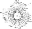
- Fig. 2 is a brief top view schematically illustrating a configuration of a damper device 1 according to the embodiment.
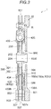
- Fig. 3 is a brief sectional view schematically illustrating the configuration of the damper device 1 illustrated in Fig. 2 , which is taken along line A-A.
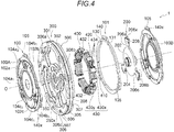
- Fig. 4 is a brief perspective view illustrating the configuration of the damper device 1 according to the embodiment, in which each configuration element is illustrated in an exploded view.
- Fig. 2 is a brief top view schematically illustrating a configuration of a damper device 1 according to the embodiment.
- Fig. 3 is a brief sectional view schematically illustrating the configuration of the damper device 1 illustrated in Fig. 2 , which is taken along line A-A.
- Fig. 4 is a brief perspective view illustrating the configuration of the damper device 1 according to the embodiment, in which each configuration element is illustrated in an exploded view.
- first disc plate 100A and a second disc plate 100B which serve as a pair of plate members (to be described later) and one of a first intermediate plate 301 and a second intermediate plate 302 which serve as a pair of plate members (to be described later) are omitted in the illustration for convenience of the drawings.
- the damper device 1 transmits a drive force to a transmission from a drive source such as an engine and a motor by being pinched between a flywheel 20 and a pressure plate (not illustrated), for example.
- a drive source such as an engine and a motor
- a structure for pinching the damper device 1 between the flywheel 20 and the pressure plate is well known. Accordingly, detailed description thereof will be omitted.
- the damper device 1 absorbs and attenuates a torque vibration.
- the damper device 1 mainly includes a disc plate 100 serving as a first rotating body, a hub 200 serving as a second rotating body, an intermediate member 300, an elastic mechanism 400 including a first elastic body 410 and a second elastic body 420, and a dynamic vibration absorber 500.
- the hub 200 is formed of a metal material, has a substantially annularly extending shape as a whole, and is disposed around a central axis O so as to be relatively rotatable with respect to the disc plate 100 (to be described later).
- the hub 200 can be joined in a spline joining method by inserting an input shaft 1000 of a transmission into a through-hole 204 formed in a cylindrical portion 202 having a substantially cylindrical shape.
- the hub 200 has a flange 206 having a substantially annular shape extending from the cylindrical portion 202 in a radial direction.
- the hub 200 can adopt, for example, a configuration in which the cylindrical portion 202 and the flange 206 are integrated with each other, and a configuration in which the cylindrical portion 202 and the flange 206 are separated from each other and a micro spring is installed between both of these.
- An outer periphery of the flange 206 has at least one notch formed along a circumferential direction.
- the outer periphery of the flange 206 has three notches 206a, 206b, and 206c formed at an equal interval along the circumferential direction (interval of 120 degree in the circumferential direction).
- the flange 206 in a top view of the damper device 1, if the damper device 1 is conceptually divided into three regions I, II, and III each having a fan shape, the flange 206 has the first notch 206a, the second notch 206b, and the third notch 206c which are respectively associated with the regions I to III.
- the number of the notches is not limited to three.
- the notches are disposed in association with a configuration of the elastic mechanism 400 (to be described later), more specifically, the number of elastic units including the first elastic body 410 and the second elastic body 420 as one set.
- the first notch 206a, the second notch 206b, and the third notch 206c can accommodate the elastic mechanism 400 (to be described later) by forming the notches in this way.
- the flange 206 has an engagement portion (first engagement portion on one end side) 208a 1 on one end side and an engagement portion (first engagement portion on the other end side) 208a 2 on the other end side facing the one end side.
- the flange 206 has an engagement portion (second engagement portion on one end side) 208b 1 on one end side and an engagement portion (second engagement portion on the other end side) 208b 2 on the other end side facing the one end side.
- the flange 206 has an engagement portion (third engagement portion on one end side) 208c 1 on one end side and an engagement portion (third engagement portion on the other end side) 208c 2 on the other end side facing the one end side.
- the engagement portions 208a 1 , 208b 1 , and 208c 1 on each one end side can have the same configuration, and the engagement portions 208a 2 , 208b 2 , and 208c 2 on each other end side can have the same configuration.
- the engagement portions 208a 1 , 208b 1 , and 208c 1 on each one end side can have a configuration symmetrical with that of the engagement portions 208a 2 , 208b 2 , and 208c 2 on each other end side.
- the disc plate 100 on the input side in the power transmission path is formed of a metal material, for example. As illustrated in Figs. 2 to 4 , the disc plate 100 is disposed across the hub 200 and the intermediate member 300 (to be described later) to be rotatable around the hub 200 and the central axis O.
- the disc plate 100 includes the first disc plate 100A and the second disc plate 100B which serve as a pair of plate members disposed on both sides of the hub 200 and the intermediate member 300 (to be described later) in an axial direction.
- the first disc plate 100A and the second disc plate 100B have a symmetrical shape in the axial direction.
- a spacer 101 which can properly adjust both positions in the axial direction is interposed therebetween, and both of these are joined to each other by using a plurality of rivets R and the like via a through-hole 105 in the vicinity of both outer peripheries.
- the first disc plate 100A and the second disc plate 100B have a shape that swells in the axial direction so as to form accommodation regions (three accommodation regions in an example illustrated in Fig. 2 ) for accommodating the elastic mechanism 400.
- Each accommodation region extends in a substantially linear shape or in a substantially arc shape along the circumferential direction of the disc plate 100 in order to accommodate the first elastic body 410 and the second elastic body 420 which extend along the circumferential direction of the disc plate 100.
- the first disc plate 100A and the second disc plate 100B form a first accommodation region 102a, a second accommodation region 102b, and a third accommodation region 102c which respectively extend along the circumferential direction.
- the first accommodation region 102a is formed to correspond to the aforementioned first notch 206a
- the second accommodation region 102b is formed to correspond to the aforementioned second notch 206b
- the aforementioned third accommodation region 102c is formed to correspond to the third notch 206c (The number of the accommodation regions also corresponds to the number of the notches disposed in the hub 200).
- the first disc plate 100A and the second disc plate 100B include one end surface (first one end surface) 104a 1 and the other end surface (first other end surface) 104a 2 facing the one end surface, as a side wall that surrounds the first accommodation region 102a.
- the first one end surface 104a 1 and the first other end surface 104a 2 extend along the axial direction of the disc plate 100.
- the first disc plate 100A and the second disc plate 100B include one end surface (second one end surface) 104b 1 and the other end surface (second other end surface) 104b 2 facing the one end surface, as a side wall that surrounds the second accommodation region 102b.
- the first disc plate 100A and the second disc plate 100B include one end surface (third one end surface) 104c 1 and the other end surface (third other end surface) 104c 2 facing the one end surface, as a side wall that surrounds the third accommodation region 102c.
- a main portion of the disc plate 100 (first disc plate 100A or second disc plate 100B) is omitted in the illustration for convenience.
- a gap G (not illustrated) for receiving the engagement portion 208a 1 on the first one end side is formed between the first one end surface 104a 1 formed by the first disc plate 100A and the first one end surface 104a 1 formed by the second disc plate 100B so that the engagement portion 208a 1 on the first one end side of the flange 206 in the hub 200 can enter the inside of the first accommodation region 102a.
- the gap G (not illustrated) for receiving the engagement portion 208a 2 on the first other end side is similarly formed between the first other end surface 104a 2 formed by the first disc plate 100A and the first other end surface 104a 2 formed by the second disc plate 100B so that the engagement portion 208a 2 on the first other end side can enter the inside of the first accommodation region 102a.
- These structures are similarly formed in the regions II and III.
- the hub 200 is excessively and relatively rotated with respect to the disc plate 100.
- the disc plate 100 (more specifically, the spacer 101) has a first stopper 130 that restricts the relative rotation of the hub 200.
- a shape of the first stopper 130 is not particularly limited as long as the relative rotation of the hub 200 can be restricted.
- a notch 131 capable of accommodating a tip portion 206x of the flange 206 in the hub 200 is disposed on an inner diameter side of the spacer 101, and a side wall of the notch 131 is used as the first stopper 130 capable of coming into contact with the tip portion 206x.
- the intermediate member 300 (to be described later) is excessively and relatively rotated with respect to the disc plate 100.
- the spacer 101 has a second stopper 140 that restricts the relative rotation of the intermediate member 300.
- the second stopper 140 may be disposed in a pair of the first disc plate A and the second disc plate B instead of the spacer 101.
- a shape of the second stopper 140 is not particularly limited as long as the relative rotation of the intermediate member 300 can be restricted.
- a projecting portion capable of being accommodated in a notch 350 to be disposed in the intermediate member 300 is disposed outside the spacer 101 in the radial direction or outside the first disc plate A and the second disc plate B in the radial direction, and the projecting portion is used as the second stopper 140 capable of coming into contact with a side wall 350x of the notch 350 (in a case where the second stopper 140 is disposed in the first disc plate A and the second disc plate B, a projecting portion 140x in Fig. 4 is used as the second stopper 140).
- the intermediate member 300 is formed of a metal material, for example. As illustrated in Figs. 2 to 4 , the intermediate member 300 is disposed across the hub 200 in the axial direction so as to be coaxial with the disc plate 100 and the hub 200 and relatively rotatable around the central axis O with respect to both of these.
- the intermediate member 300 includes the first intermediate plate 301 and the second intermediate plate 302 which serve as a pair of plate members disposed on both sides of the hub 200 in the axial direction.
- the first intermediate plate 301 and the second intermediate plate 302 have the same shape, and are fixed to each other by fixing means such as a fastening pin 310 so that both of these are rotatable integrally with each other.
- the first intermediate plate 301 and the second intermediate plate 302 may have mutually different shapes. For example, based on a difference in each rotational inertia mass between the first disc plate 100A and the second disc plate 100B, the first intermediate plate 301 can have a larger (or smaller) shape than the second intermediate plate 302 so that the first intermediate plate 301 has larger (or smaller) rotational inertia mass. In this manner, the damper device 1 as a whole can have an improved balance of the rotational inertia mass, and inclination with respect to the rotation center O can be reduced.
- the first intermediate plate 301 and the second intermediate plate 302 respectively have a disc-shaped inner circle portion 305, an annular outer ring portion 307, and a connecting portion 306 that connects the inner circle portion 305 and the outer ring portion 307 to each other.
- the inner circle portion 305 has an insertion hole 308 into which the hub 200 and a stepped bush 600 attached to an outer peripheral side of the cylindrical portion 202 of the hub 200 can be inserted.
- the first intermediate plate 301 and the second intermediate plate 302 are axially supported by the hub 200 via the bush 600 by connecting the inner circle portion 305 to the bush 600. Accordingly, the first intermediate plate 301 and the second intermediate plate 302 are reliably aligned in the axial direction and the radial direction. In this manner, misalignment of the first intermediate plate 301 and the second intermediate plate 302 is suppressed in the axial direction and the radial direction.
- a configuration may be adopted in which only one of the first intermediate plate 301 and the second intermediate plate 302 is axially supported by the hub 200. In this manner, the rotational inertia mass of the pair of intermediate members 300 can be reduced.
- the first intermediate plate 301 and the second intermediate plate 302 may be aligned only in one direction of the axial direction and the radial direction. In this manner, assembling performance can be improved.
- the connecting portion 306 extends outward in the radial direction from an outer peripheral end of the inner circle portion 305, and connects the inner circle portion 305 and the outer ring portion 307 to each other.
- the connecting portion 306 has a first connecting portion 306a corresponding to the first accommodation region 102a disposed in the first notch 206a and the disc plate 100 which are disposed in the hub 200, a second connecting portion 306b corresponding to the second accommodation region 102b disposed in the second notch 206b and the disc plate 100 which are disposed in the hub 200, and a third connecting portion 306c corresponding to the third accommodation region 102c disposed in the third notch 206c and the disc plate 100 which are disposed in the hub 200.
- the first connecting portion 306a is accommodated between the first elastic body 410 and the second elastic body 420 in the elastic mechanism 400, and engages with each of a first sheet member 430x that supports the first elastic body 410 and a second sheet member 430y that supports the second elastic body 420.
- the second connecting portion 306b and the third connecting portion 306c also engage with the first sheet member 430x and the second sheet member 430y, as in the first connecting portion 306a.
- An engagement structure between the first connecting portion 306a (and the second connecting portion 306b and the third connecting portion 306c) and the first sheet member 430x and the second sheet member 430y will be described in detail later.
- the outer ring portion 307 forms an outer diameter of the intermediate member 300, and is disposed to support the dynamic vibration absorber 500 (to be described later).
- the intermediate member 300 has the outer ring portion 307. In this manner, as illustrated in Fig. 4 , the outer diameter of the intermediate member 300 is set to be larger than the outer diameter of the elastic mechanism 400. Accordingly, without interfering with other configuration elements, the dynamic vibration absorber 500 can be reliably located at a position facing the outer ring portion 307 (outer peripheral end of the intermediate member 300).
- the notch 350 (and the side wall 350x) capable of accommodating the second stopper 140 is (are) disposed in the outer ring portion 307.
- the elastic mechanism 400 is configured to mainly include the first elastic body 410 using the coil spring, the second elastic body 420 similarly using the coil spring, a sheet member 430 (the first sheet member 430x and the second sheet member 430y) that supports the first elastic body 410 or the second elastic body 420, and a floating elastic body 440.
- the first elastic body 410 and the second elastic body 420 are located to be aligned one by one in series in the circumferential direction, thereby forming a set of elastic units.
- a case is assumed where a positive torque is transmitted counterclockwise from a drive source such as an engine and a motor.
- the first elastic body 410 and the second elastic body 420 are located in each elastic unit in the order (order in which the second elastic body 420 is located next to the left rotation of the first elastic body 410). In a case where the positive torque is transmitted clockwise, the first elastic body 410 and the second elastic body 420 are located in each elastic unit in the order in which the second elastic body 420 is located next to the right rotation of the first elastic body 410.
- the disc plate 100 has the three accommodation regions, that is, the first accommodation region 102a to the third accommodation region 102c (the hub 200 has the three notches, that is, the first notch 206a to the third notch 206c).
- one elastic unit one first elastic body 410 and one second elastic body 420
- each of the three accommodation regions that is, in association with the respective regions I to III.
- both ends of the first elastic body 410 are supported by the pair of first sheet members 430x
- both ends of the second elastic body 420 are supported by the pair of second sheet members 430y.
- the elastic mechanism 400 is located in an annular shape as a whole by the three elastic units and the sheet member 430.
- one end of the first sheet member 430x that supports the first elastic body 410 engages with each of the first other end surface 104a 2 disposed in the disc plate 100 and the engagement portion 208a 2 on the first other end side disposed in the hub 200.
- the other end of the first sheet member 430x that supports the first elastic body 410 engages with the first connecting portion 306a in the intermediate member 300.
- one end of the first sheet member 430x has a first groove portion 432, and the engagement portion 208a 2 on the first other end side disposed in the hub 200 is accommodated in the first groove portion 432, thereby enabling one end of the first sheet member 430x and the hub 200 to engage with each other.
- the other end of the first sheet member 430x has a second groove portion 434, and the first connecting portion 306a in the intermediate member 300 is accommodated in the second groove portion 434, thereby enabling the other end of the first sheet member 430x and the Intermediate member 300 to engage with each other.
- one end of the second sheet member 430y that supports the second elastic body 420 engages with the first connecting portion 306a in the intermediate member 300, and the other end of the second sheet member 430y that supports the second elastic body 420 engages with each of the first one end surface 104a 1 disposed in the disc plate 100 and the engagement portion 208a 1 on the first one end side disposed in the hub 200.
- one end of the second sheet member 430y also has the second groove portion 434, and the first connecting portion 306a in the intermediate member 300 is accommodated in the second groove portion 434, thereby enabling one end of the second sheet member 430y and the intermediate member 300 to engage with each other.
- the other end of the second sheet member 430y also has the first groove portion 432, and the engagement portion 208a 1 on the first one end side disposed in the hub 200 is accommodated in the first groove portion 432, thereby enabling the other end of the second sheet member 430y and the hub 200 to engage with each other.
- one end of the first sheet member 430x that supports the first elastic body 410 engages with each of the second other end surface 104b 2 disposed in the disc plate 100 and the engagement portion 208b 2 on the second other end side disposed in the hub 200.
- the other end of the first sheet member 430x that supports the first elastic body 410 engages with the second connecting portion 306b in the intermediate member 300.
- one end of the second sheet member 430y that supports the second elastic body 420 engages with the second connecting portion 306b in the intermediate member 300, and the other end of the second sheet member 430y that supports the second elastic body 420 engages with each of the second one end surface 104b 1 disposed in the disc plate 100 and the engagement portion 208b 1 on the second one end side disposed in the hub 200.
- the first sheet member 430x and the second sheet member 430y have the first groove portion 432 and the second groove portion 434.
- one end of the first sheet member 430x that supports the first elastic body 410 engages with each of the third other end surface 104c 2 disposed in the disc plate 100 and the engagement portion 208c 2 on the third other end side disposed in the hub 200.
- the other end of the first sheet member 430x that supports the first elastic body 410 engages with the third connecting portion 306c in the intermediate member 300.
- one end of the second sheet member 430y that supports the second elastic body 420 engages with the third connecting portion 306c in the intermediate member 300, and the other end of the second sheet member 430y that supports the second elastic body 420 engages with each of the third one end surface 104c 1 disposed in the disc plate 100 and the engagement portion 208c 1 on the third one end side disposed in the hub 200.
- the first sheet member 430x and the second sheet member 430y have the first groove portion 432 and the second groove portion 434.
- Each of the elastic units having the above-described configuration accommodates the intermediate member 300 (the first connecting portion 306a to the third connecting portion 306c) between the first elastic body 410 and the second elastic body 420. More precisely, the intermediate member 300 is accommodated between the first sheet member 430x and the second sheet member 430y.
- the first elastic body 410 can elastically couple the disc plate 100 and the intermediate member 300 with each other in the rotation direction (the counterclockwise rotation direction) via the first sheet member 430x
- the second elastic body 420 can elastically couple the intermediate member 300 and the hub 200 with each other via the second sheet member 430y. That is, the power output from the drive source such as the engine and the motor is basically transmitted to the disc plate 100, the first sheet member 430x on one side, the first elastic body 410, the first sheet member 430x on the other side, the intermediate member 300, the second sheet member 430y on one side, the second elastic body 420, the second sheet member 430y on the other side, and the hub 200 in this order.
- the floating elastic body 440 is accommodated inside the first elastic body 410 as illustrated in Fig. 2 .
- the floating elastic body 440 may be any elastic body as long as the floating elastic body 440 has a spring constant higher than a spring constant of the first elastic body 410.
- styrene/butadiene rubber or ethylene/propylene rubber may be used.
- the floating elastic body 440 has the spring constant higher than the spring constant of the first elastic body 410 as described above. Accordingly, as will be described later, if the first elastic body 410 elastically deforms and the floating elastic body 440 is once pinched by a pinching portion 431 disposed in the first sheet member 430x, the subsequent elastic deformation of the first elastic body 410 depends on the spring constant of the floating elastic body 440. That is, torsional rigidity of the first elastic body 410 can be improved.
- a shape of the floating elastic body 440 is not particularly limited. However, for example, it is preferable that an overall shape of the floating elastic body 440 is a substantially columnar shape, a substantially prismatic shape, or a substantially cross shape so as not to fit between winding pitches of the first elastic body 410. Alternatively, it is preferable that the floating elastic body 440 has a surface capable of coming into surface contact with the pinching portion 431 in the first sheet member 430x.
- a length of the floating elastic body 440 can be set as appropriate depending on a size of a required torsional angle or the rigidity of the first elastic body 410. However, as a matter of course, the length of the floating elastic body 440 is set to be shorter than the length of the first elastic body 410. In order to ensure the surface contact with the pinching portion 431, it is preferable that the outer diameter of the floating elastic body 440 is substantially the same as the inner diameter of the first elastic body 410. In this manner, the floating elastic body 440 can be prevented from being misaligned in the radial direction based on a centrifugal force inside the first elastic body 410.
- the floating elastic body 440 may be disposed not only inside the first elastic body 410 but also inside the second elastic body 420 (refer to Figs. 6A to 6E ).
- the dynamic vibration absorber 500 can adopt a generally known centrifugal pendulum type that mainly includes a pair of mass bodies (first mass body 501 and second mass body 502) serving as weights attached to the pair of intermediate members 300 (first intermediate plate 301 and second intermediate plate 302), a rolling hole 505a disposed in each mass body, and a rolling shaft 507 disposed inside the rolling hole 505a.
- the plate-shaped first mass body 501 and the plate-shaped second mass body 502 are paired together, and are located on a surface of the intermediate member 300 across both the first intermediate plate 301 and the second intermediate plate 302, specifically, at a position facing the outer peripheral end of the outer ring portion 307. That is, the first mass body 501 is located at a position facing the outer peripheral end of the outer ring portion 307 of the first intermediate plate 301, and the second mass body 502 is located at a position facing the outer peripheral end of the outer ring portion 307 of the second intermediate plate 302. Furthermore, the first mass body 501 and the second mass body 502 respectively have the rolling holes 505a, and the rolling shaft 507 is disposed to penetrate the two rolling holes 505a.
- the first intermediate plate 301 that supports the first mass body 501 and the second intermediate plate 302 that supports the second mass body 502 respectively have a through-hole 505b for the rolling shaft 507 to penetrate from the rolling hole 505a disposed in the first mass body 501 to the rolling holes 505a disposed in the second mass body 502.
- the shape of the through-hole 505b is designed to correspond to the shape of the rolling hole 505a (to be described later). For example, as will be described later, in a case where the shape of the rolling hole 505a adopts a shape extending in a curved shape bulging toward the rotation center O of the intermediate member 300, (for example, in Fig.
- a shape substantially projecting upward in the drawing correspondingly, it is possible to adopt a shape extending in a curved shape (most preferably, an arc shape or a substantially arc shape) bulging outward in the radial direction of the intermediate member 300 (for example, in Fig. 2 , a shape substantially projecting downward in the drawing).
- the shapes of the first mass body 501 and the second mass body 502 are the same as each other, and the shape is not particularly limited. However, as illustrated in Figs. 2 to 4 , it is possible to adopt a substantially arc shape formed along the shape (outer periphery) of the outer ring portion 307 of the intermediate member 300 so that the outer diameter as the damper device 1 does not increase.
- the number of the rolling holes 505a disposed in the first mass body 501 and the second mass body 502 is not particularly limited. However, as illustrated in Figs. 2 and 4 , in view of a weight balance, it is preferable that two or more rolling holes 505a are symmetrically disposed along the circumferential direction by using the center of the first mass body 501 (the second mass body 502) in the circumferential direction as an axis.
- As the shape of the rolling hole 505a it is possible to adopt a shape capable of accommodating the rolling shaft 507 and extending in a curved shape (most preferably, an arc shape or a substantially arc shape) bulging toward the rotation center O of the intermediate member 300 (for example, in Fig. 2 , a shape substantially projecting upward in the drawing).
- the number of the rolling holes 505a disposed in the first mass body 501 and the number of the rolling holes 505a disposed in the second mass body 502 are the same as each other.
- the rolling shaft 507 has a middle thick portion 507x in the vicinity of the center position when viewed in the axial direction so that the rolling shaft 507 can maintain a located state where the rolling shaft 507 penetrates the rolling hole 505a and the through-hole 505b.
- the dynamic vibration absorber 500 has three dynamic vibration absorbing units to correspond to the regions I to III. It is preferable that each of the dynamic vibration absorbing units is disposed at a position having the same diameter as the outer diameter of the spacer 101 (radial position having the above-described rivet R) with reference to the rotation center O. In other words, it is preferable to dispose the spacer 101 having the outer diameter at the radial position where each of the dynamic vibration absorbing units is disposed. In this manner, the intermediate member 300 can be reduced in diameter, and the damper device 1 as a whole can have a compact size in the radial direction.
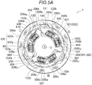
- Figs. 5A and 5B are brief top views schematically illustrating a state where the damper device 1 illustrated in Fig. 2 is operated and the hub 200 relatively rotates with respect to the disc plate 100.
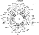
- Fig. 5C is a brief top view schematically illustrating a state where relative rotation is restricted after the damper device 1 illustrated in Fig. 2 is operated and the hub 200 relatively rotates with respect to the disc plate 100.
- Fig. 7 is a brief characteristic diagram schematically illustrating the torsional characteristic in the damper device 1 according to the embodiment.
- the damper device 1 illustrated in Fig. 2 indicates a state where the drive force is transmitted to the damper device 1 from the drive source such as the engine and the motor so that the disc plate 100, the hub 200, and the intermediate member 300 rotate integrally with each other without the relative rotation.
- the power output from the drive source such the engine and the motor is transmitted to the disc plate 100, the first sheet member 430x on one side, the first elastic body 410, the first sheet member 430x on the other side, the intermediate member 300, the second sheet member 430y on one side, the second elastic body 420, the second sheet member 430y on the other side, and the hub 200 in this order.
- the power is transmitted from the first other end surface 104a 2 disposed in the disc plate 100 to the first sheet member 430x on one side. While the first sheet member 430x on one side bends the first elastic body 410, the power is transmitted to the first sheet member 430x on the other side.
- the first sheet member 430x on the other side transmits the power to the first connecting portion 306a in the intermediate member 300. While bending the second elastic body 420 via the second sheet member 430y on one side, the first connecting portion 306a transmits the power to the second sheet member 430y on the other side. Finally, the power is transmitted from the second sheet member 430y on the other side to the hub 200 (engagement portion 208a 1 on the first one end side), and the power is transmitted to the hub 200.
- the power is similarly transmitted by operating each of the configuration elements.
- FIG. 5A schematically illustrates a state where the hub 200 and the intermediate member 300 relatively rotate with respect to the disc plate 100 by a predetermined torsional angle ⁇ 1 (rotational phase difference is ⁇ 1 ).
- the hub 200 and the intermediate member 300 rotate with respect to the disc plate 100 in the same rotation direction as that of the power transmission (in the embodiment, counterclockwise). More specifically, the hub 200 rotates counterclockwise by the rotational phase difference ⁇ 1 while bending the first elastic body 410.
- the intermediate member 300 rotates counterclockwise by the rotational phase difference ⁇ 1 while bending the second elastic body 420.
- the pinching portion 431 of the pair of first sheet members 430x supporting the first elastic body 410 comes into contact with the floating elastic body 440 to be accommodated inside the first elastic body 410.
- the spring constant of the floating elastic body 440 is set to be higher than the spring constant of the first elastic body 410. Accordingly, after the pinching portion 431 of the first sheet member 430x pinches the floating elastic body 440 (in a case where the torsional angle is equal to or larger than ⁇ 1 ), the torsional rigidity of the first elastic body 410 becomes higher.
- the tip portion 206x of the flange 206 is not in contact with the first stopper 130. Accordingly, the relative rotation of the hub 200 is not restricted.
- the side wall 350x of the notch 350 disposed in the intermediate member 300 is not in contact with the second stopper 140. Accordingly, the relative rotation of the intermediate member 300 is also not restricted.
- a state will be described where the hub 200 and the intermediate member 300 relatively rotate with respect to the disc plate 100 by the torsional angle ⁇ 2 ( ⁇ 2 > ⁇ 1 ) (rotational phase difference is ⁇ 2 ).
- the hub 200 and the intermediate member 300 rotate further counterclockwise with respect to the disc plate 100 from the state illustrated in Fig. 5A . More specifically, as described above, the hub 200 further rotates counterclockwise by the rotational phase difference ⁇ 2 - ⁇ 1 while bending the first elastic body 410 having the high torsional rigidity.
- the intermediate member 300 rotates further counterclockwise by the rotational phase difference ⁇ 2 - ⁇ 1 while bending the second elastic body 420.
- a state will be described where the hub 200 relatively rotates with respect to the disc plate 100 by a torsional angle ⁇ 3 ( ⁇ 3 > ⁇ 2 ) (rotational phase difference is ⁇ 3 ).
- the hub 200 rotates further counterclockwise from the state illustrated in Fig. 5B with respect to the disc plate 100 (relative rotation of the intermediate member 300 is already restricted by the second stopper 140). More specifically, as described above, the hub 200 rotates further counterclockwise by a rotational phase difference ⁇ 3 - ⁇ 2 while bending the first elastic body 410 having the higher torsional rigidity. Finally, the tip portion 206x of the flange 206 comes into contact with the first stopper 130. In this manner, the relative rotation of the hub 200 is also restricted.
- the damper device 1 according to the embodiment has the three stage torsional characteristic. More specifically, as illustrated in Fig. 7 , the damper device 1 according to the embodiment has a first stage characteristic X in a range where the torsional angle is from 0 to ⁇ 1 , has a second stage characteristic Y having the higher torsional rigidity than the characteristic X in a range where the torsional angle is from ⁇ 1 to ⁇ 2 , and has a third stage characteristic Z having the higher torsional rigidity than the characteristic Y in a range where the torsional angle is from ⁇ 2 to ⁇ 3 .
- the damper device 1 according to the embodiment can suppress a sudden characteristic change in the torsional rigidity (the characteristic can be gradually changed from the characteristic X to the characteristic Z). Therefore, an impact or vibration caused by the characteristic change can be suppressed.
- Fig. 6A is a brief top view schematically illustrating the configuration of the damper device 1 according to another embodiment.
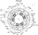
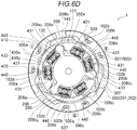
- Figs. 6B to 6D are brief top views schematically illustrating a state where the damper device 1 illustrated in Fig. 6A is operated and the hub 200 relatively rotates with respect to the disc plate 100.
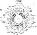
- Fig. 6E is a brief top view schematically illustrating a state where the relative rotation is restricted after the damper device 1 illustrated in Fig. 6A is operated and the hub 200 relatively rotates with respect to the disc plate 100.
- the configuration and the operation of the damper device 1 according to another embodiment are almost common to those of the damper device 1 according to the above-described embodiment. Accordingly, detailed description of the common configuration and operation will be omitted.
- the damper device 1 according to another embodiment is different from the above-described embodiment in that the floating elastic body 440 is accommodated inside the second elastic body 420 as illustrated in Fig. 6A (common configuration in the regions I to III). Accordingly, the pinching portion 431 for pinching the floating elastic body 440 is also disposed in the pair of second sheet members 430y supporting the second elastic body 420. Other points are common to those of the damper device 1 according to the above-described embodiment.
- the operation of the damper device 1 according to another embodiment is basically the same as the operation of the damper device 1 according to the above-described embodiment.
- the floating elastic body 440 is also disposed inside the second elastic body 420. Therefore, the damper device 1 according to another embodiment has a four stage torsional characteristic.
- FIG. 6B schematically illustrates a state where the hub 200 and the intermediate member 300 relatively rotate with respect to the disc plate 100 by a predetermined torsional angle ⁇ A (rotational phase difference is ⁇ A ).
- the hub 200 rotates counterclockwise by the rotational phase difference ⁇ A while bending the first elastic body 410.
- the intermediate member 300 rotates counterclockwise by the rotational phase difference ⁇ A while bending the second elastic body 420.
- the pinching portion 431 of the pair of first sheet members 430x supporting the first elastic body 410 comes into contact with the floating elastic body 440 to be accommodated inside the first elastic body 410.
- the spring constant of the floating elastic body 440 is set to be higher than the spring constant of the first elastic body 410. Accordingly, after the pinching portion 431 of the first sheet member 430x pinches the floating elastic body 440 (in a case where the torsional angle is equal to or larger than ⁇ A ), the torsional rigidity of the first elastic body 410 becomes higher (torsional characteristic is changed from the first stage torsional characteristic to the second stage torsional characteristic).
- the tip portion 206x of the flange 206 is not in contact with the first stopper 130. Accordingly, the relative rotation of the hub 200 is not restricted.
- the side wall 350x of the notch 350 disposed in the intermediate member 300 is not in contact with the second stopper 140. Accordingly, the relative rotation of the intermediate member 300 is also not restricted.
- the pinching portion 431 of the pair of second sheet members 430y supporting the second elastic body 420 is not in contact with the floating elastic body 440 accommodated inside the second elastic body 420.
- a state will be described where the hub 200 and the intermediate member 300 relatively rotate with respect to the disc plate 100 by a torsional angle ⁇ B ( ⁇ B > ⁇ A ) (rotational phase difference is ⁇ B ).
- the hub 200 and the intermediate member 300 rotate further counterclockwise with respect to the disc plate 100 from the state illustrated in Fig. 6B . More specifically, as described above, the hub 200 rotates further counterclockwise by a rotational phase difference ⁇ B - ⁇ A while bending the first elastic body 410 having the higher torsional rigidity.
- the intermediate member 300 rotates further counterclockwise by the rotational phase difference ⁇ B - ⁇ A while bending the second elastic body 420.
- the pinching portion 431 of the pair of second sheet members 430y supporting the second elastic body 420 comes into contact with the floating elastic body 440 accommodated inside the second elastic body 420. Therefore, after the pinching portion 431 of the second sheet member 430y pinches the floating elastic body 440 (in a case where the torsional angle is larger than ⁇ B ), the torsional rigidity of the second elastic body 420 becomes higher (torsional characteristic is changed from the second stage torsional characteristic to the third stage torsional characteristic).
- the spring constant of the first elastic body 410 and the second elastic body 420 may be set to be lower than the spring constant of the coil spring used for the second elastic body 420.
- a state will be described where the hub 200 and the intermediate member 300 relatively rotate with respect to the disc plate 100 by a torsional angle ⁇ C ( ⁇ C > ⁇ B ) (rotational phase difference is ⁇ C ).
- the hub 200 and the intermediate member 300 rotate further counterclockwise with respect to the disc plate 100 from the state illustrated in Fig. 6C . More specifically, as described above, the hub 200 rotates further counterclockwise by a rotational phase difference ⁇ C - ⁇ B while bending the first elastic body 410 having the higher torsional rigidity.
- the intermediate member 300 rotates further counterclockwise by the rotational phase difference ⁇ C - ⁇ B while bending the second elastic body 420 having the higher torsional rigidity.
- a state will be described where the hub 200 relatively rotates with respect to the disc plate 100 by a torsional angle ⁇ D ( ⁇ D > ⁇ C ) (rotational phase difference is ⁇ D ).
- the hub 200 rotates further counterclockwise with respect to the disc plate 100 from the state illustrated in Fig. 6D (relative rotation of the intermediate member 300 is already restricted by the second stopper 140). More specifically, as described above, the hub 200 rotates further counterclockwise by a rotational phase difference ⁇ D - ⁇ C while bending the first elastic body 410 having the higher torsional rigidity. Finally, the tip portion 206x of the flange 206 comes into contact with the first stopper 130. In this manner, the relative rotation of the hub 200 is also restricted.
- the damper device 1 has the four stage torsional characteristic. More specifically, the damper device 1 has a first characteristic on the first stage in a range where the torsional angle is from 0 to ⁇ A , has a second characteristic on the second stage having the higher torsional rigidity than the first characteristic in a range where the torsional angle is from ⁇ A to ⁇ B , has a third characteristic on the third stage having the higher torsional rigidity than the second characteristic in a range where the torsional angle is from ⁇ B to ⁇ C , and has a fourth characteristic on the fourth stage having the higher torsional rigidity than the third characteristic in a range where the torsional angle is from ⁇ C to ⁇ D .
- the damper device 1 according to another embodiment can further suppress a sudden characteristic change in the torsional rigidity. Accordingly, the impact or the vibration caused by the characteristic change can be more efficiently suppressed.
Landscapes
- Engineering & Computer Science (AREA)
- General Engineering & Computer Science (AREA)
- Physics & Mathematics (AREA)
- Acoustics & Sound (AREA)
- Aviation & Aerospace Engineering (AREA)
- Mechanical Engineering (AREA)
- Mechanical Operated Clutches (AREA)
Abstract
Description
- A technique disclosed in this disclosure relates to a damper device.
- In a vehicle or the like, a damper device which absorbs a vibration of a torque transmitted to a transmission from a drive source such as an engine is disposed on a torque transmission path between the drive source and the transmission. For example, the damper device is incorporated in a clutch device.
- As a general configuration of the damper device, a technique is known in which the vibration in a torsional direction caused by torque fluctuations is absorbed and attenuated in such a way that elastic deformation of a coil spring is used by interposing the coil spring between a first rotating body (for example, a disc plate) serving as an input member and a second rotating body (for example, a hub) serving as an output member, both of which can relatively rotate with respect to each other.
- As a specific configuration of the damper device,
JP H7-293578A JP 2018-112223A JP H7-293578A - In a hybrid vehicle which uses the engine and an electric motor as the drive source, an inertial force is present due to not only the engine but also the heavy electric motor having a heavy load. Consequently, compared to a vehicle which uses only the engine as the drive source in the related art, it is known that noise or the vibration generally increases in the hybrid vehicle. Therefore, in recent years, the damper device itself needs performance improvement. In this regard, Pamphlet of International Publication No.
WO2017/032370 proposes a technique as follows. An intermediate member is disposed between the input member and the output member, and a dynamic vibration absorber is located in the intermediate member. - However, according to the damper device disclosed in each of
JP H7-293578A JP 2018-112223A Fig. 1 . In a case of the damper device, when the characteristic is switched from the characteristic A to the characteristic B (or from the characteristic B to the characteristic A), there is a problem in that an impact or the vibration may be caused by a sudden characteristic change. - Thus, a need exists for a high-performance damper device in which the impact or the vibration is suppressed even at a characteristic switching timing.
- A damper device according to an aspect of this disclosure includes a first rotating body, a second rotating body coaxial with the first rotating body, and relatively rotating with respect to the first rotating body, an intermediate member coaxial with the first rotating body and the second rotating body and relatively rotating with respect to the first rotating body, and an elastic mechanism that has a first elastic body elastically coupling the first rotating body and the intermediate member with each other in a rotation direction, a second elastic body elastically coupling the intermediate member and the second rotating body with each other in the rotation direction, a pair of first sheet members supporting the first elastic body, a pair of second sheet members supporting the second elastic body and a floating elastic body to be accommodated inside at least one of the first elastic body and the second elastic body. The first rotating body further has a first stopper restricting relative rotation of the second rotating body, and a second stopper restricting relative rotation of the intermediate member.
- According to this configuration, the damper device has a torsional characteristic including at least three or more stages. In this manner, a sudden characteristic change is suppressed. As a result, it is possible to suppress an impact or a vibration caused by the characteristic change.
- In the damper device according to the aspect, it is preferable that a pinching portion for pinching the floating elastic body is provided to at least one of the pair of first sheet members and the pair of second sheet members.
- According to this configuration, it is possible to efficiently express the torsional characteristic using the floating elastic body.
- In the damper device according to the aspect, it is preferable that a pair of the intermediate members are disposed across the second rotating body.
- According to this configuration, the damper device can have the torsional characteristic including at least three or more stages, and the impact or the vibration can be efficiently attenuated.
- In the damper device according to the aspect, it is preferable that the first rotating body has a pair of plate members and a spacer to be accommodated between the pair of plate members, the second stopper is disposed in the plate member, and the first stopper is disposed in the spacer.
- According to this configuration, the damper device can have the torsional characteristic including at least three or more stages.
- In the damper device according to the aspect, it is preferable that the first rotating body has a pair of plate members and a spacer to be accommodated between the pair of plate members, and the first stopper and the second stopper are disposed in the spacer.
- According to this configuration, the damper device can have the torsional characteristic including at least three or more stages.
- According to various embodiments, it is possible to provide a high-performance damper device in which the impact or the vibration is suppressed even at a characteristic switching timing.
- The foregoing and additional features and characteristics of this disclosure will become more apparent from the following detailed description considered with the reference to the accompanying drawings, wherein:
-
Fig. 1 is a brief characteristic diagram schematically illustrating a torsional characteristic in a damper device in the related art; -
Fig. 2 is a brief top view schematically illustrating a configuration of a damper device according to an embodiment disclosed here; -
Fig. 3 is a brief sectional view schematically illustrating the configuration of the damper device illustrated inFig. 2 , which is taken along line A-A; -
Fig. 4 is a brief perspective view illustrating the configuration of the damper device according to the embodiment, in which each configuration element is illustrated in an exploded view; -
Fig. 5A is a brief top view schematically illustrating a state where the damper device illustrated inFig. 2 is operated and a hub relatively rotates with respect to a disc plate; -
Fig. 5B is a brief top view schematically illustrating a state where the damper device illustrated inFig. 2 is operated and the hub relatively rotates with respect to the disc plate; -
Fig. 5C is a brief top view schematically illustrating a state where relative rotation of the hub is restricted after the damper device illustrated inFig. 2 is operated and the hub relatively rotates with respect to the disc plate; -
Fig. 6A is a brief top view schematically illustrating a configuration of a damper device according to another embodiment disclosed here; -
Fig. 6B is a brief top view schematically illustrating a state where the damper device illustrated inFig. 6A is operated and a hub relatively rotates with respect to a disc plate; -
Fig. 6C is a brief top view schematically illustrating a state where the damper device illustrated inFig. 6A is operated and the hub relatively rotates with respect to the disc plate; -
Fig. 6D is a brief top view schematically illustrating a state where the damper device illustrated inFig. 6A is operated and the hub relatively rotates with respect to the disc plate; -
Fig. 6E is a brief top view schematically illustrating a state where relative rotation of the hub is restricted after the damper device illustrated inFig. 6A is operated and the hub relatively rotates with respect to the disc plate; and -
Fig. 7 is a brief characteristic diagram schematically illustrating a torsional characteristic in the damper device according to the embodiment. - Hereinafter, various embodiments disclosed here will be described with reference to the accompanying drawings. The same reference numerals will be given to configuration elements common to each other in the drawings. It should be noted that the configuration elements expressed in a certain drawing may be omitted in another drawing for convenience of description. Furthermore, it should be noted that the accompanying drawings are not necessarily illustrated by using exact scales.
- An outline of an overall configuration of a damper device according to an embodiment disclosed here will be described with reference to
Figs. 2 to 4 .Fig. 2 is a brief top view schematically illustrating a configuration of adamper device 1 according to the embodiment.Fig. 3 is a brief sectional view schematically illustrating the configuration of thedamper device 1 illustrated inFig. 2 , which is taken along line A-A.Fig. 4 is a brief perspective view illustrating the configuration of thedamper device 1 according to the embodiment, in which each configuration element is illustrated in an exploded view. InFig. 2 , it should be noted that one of afirst disc plate 100A and asecond disc plate 100B which serve as a pair of plate members (to be described later) and one of a firstintermediate plate 301 and a secondintermediate plate 302 which serve as a pair of plate members (to be described later) are omitted in the illustration for convenience of the drawings. - The
damper device 1 according to the embodiment transmits a drive force to a transmission from a drive source such as an engine and a motor by being pinched between aflywheel 20 and a pressure plate (not illustrated), for example. A structure for pinching thedamper device 1 between theflywheel 20 and the pressure plate is well known. Accordingly, detailed description thereof will be omitted. - The
damper device 1 absorbs and attenuates a torque vibration. As illustrated inFigs. 2 to 4 , thedamper device 1 mainly includes adisc plate 100 serving as a first rotating body, ahub 200 serving as a second rotating body, anintermediate member 300, anelastic mechanism 400 including a firstelastic body 410 and a secondelastic body 420, and adynamic vibration absorber 500. - For example, the
hub 200 is formed of a metal material, has a substantially annularly extending shape as a whole, and is disposed around a central axis O so as to be relatively rotatable with respect to the disc plate 100 (to be described later). As illustrated inFigs. 3 and4 , thehub 200 can be joined in a spline joining method by inserting aninput shaft 1000 of a transmission into a through-hole 204 formed in acylindrical portion 202 having a substantially cylindrical shape. Thehub 200 has aflange 206 having a substantially annular shape extending from thecylindrical portion 202 in a radial direction. Thehub 200 can adopt, for example, a configuration in which thecylindrical portion 202 and theflange 206 are integrated with each other, and a configuration in which thecylindrical portion 202 and theflange 206 are separated from each other and a micro spring is installed between both of these. - An outer periphery of the
flange 206 has at least one notch formed along a circumferential direction. According to the embodiment, as an example, the outer periphery of theflange 206 has threenotches Fig. 2 , in a top view of thedamper device 1, if thedamper device 1 is conceptually divided into three regions I, II, and III each having a fan shape, theflange 206 has thefirst notch 206a, thesecond notch 206b, and thethird notch 206c which are respectively associated with the regions I to III. The number of the notches is not limited to three. The notches are disposed in association with a configuration of the elastic mechanism 400 (to be described later), more specifically, the number of elastic units including the firstelastic body 410 and the secondelastic body 420 as one set. - The
first notch 206a, thesecond notch 206b, and thethird notch 206c can accommodate the elastic mechanism 400 (to be described later) by forming the notches in this way. In association with the region I, theflange 206 has an engagement portion (first engagement portion on one end side) 208a1 on one end side and an engagement portion (first engagement portion on the other end side) 208a2 on the other end side facing the one end side. In association with the region II, theflange 206 has an engagement portion (second engagement portion on one end side) 208b1 on one end side and an engagement portion (second engagement portion on the other end side) 208b2 on the other end side facing the one end side. In association with the region III, theflange 206 has an engagement portion (third engagement portion on one end side) 208c1 on one end side and an engagement portion (third engagement portion on the other end side) 208c2 on the other end side facing the one end side. - The engagement portions 208a1, 208b1, and 208c1 on each one end side can have the same configuration, and the engagement portions 208a2, 208b2, and 208c2 on each other end side can have the same configuration. The engagement portions 208a1, 208b1, and 208c1 on each one end side can have a configuration symmetrical with that of the engagement portions 208a2, 208b2, and 208c2 on each other end side.
- The
disc plate 100 on the input side in the power transmission path is formed of a metal material, for example. As illustrated inFigs. 2 to 4 , thedisc plate 100 is disposed across thehub 200 and the intermediate member 300 (to be described later) to be rotatable around thehub 200 and the central axis O. Thedisc plate 100 includes thefirst disc plate 100A and thesecond disc plate 100B which serve as a pair of plate members disposed on both sides of thehub 200 and the intermediate member 300 (to be described later) in an axial direction. Thefirst disc plate 100A and thesecond disc plate 100B have a symmetrical shape in the axial direction. Aspacer 101 which can properly adjust both positions in the axial direction is interposed therebetween, and both of these are joined to each other by using a plurality of rivets R and the like via a through-hole 105 in the vicinity of both outer peripheries. - In cooperation with each other, and in association with each of the regions I to III, the
first disc plate 100A and thesecond disc plate 100B have a shape that swells in the axial direction so as to form accommodation regions (three accommodation regions in an example illustrated inFig. 2 ) for accommodating theelastic mechanism 400. Each accommodation region extends in a substantially linear shape or in a substantially arc shape along the circumferential direction of thedisc plate 100 in order to accommodate the firstelastic body 410 and the secondelastic body 420 which extend along the circumferential direction of thedisc plate 100. - Specifically, referring to
Figs. 2 and4 , in association with the regions I to III, thefirst disc plate 100A and thesecond disc plate 100B form afirst accommodation region 102a, asecond accommodation region 102b, and athird accommodation region 102c which respectively extend along the circumferential direction. Thefirst accommodation region 102a is formed to correspond to the aforementionedfirst notch 206a, thesecond accommodation region 102b is formed to correspond to the aforementionedsecond notch 206b, and the aforementionedthird accommodation region 102c is formed to correspond to thethird notch 206c (The number of the accommodation regions also corresponds to the number of the notches disposed in the hub 200). - Focusing on the region I, as illustrated in
Fig. 4 , thefirst disc plate 100A and thesecond disc plate 100B include one end surface (first one end surface) 104a1 and the other end surface (first other end surface) 104a2 facing the one end surface, as a side wall that surrounds thefirst accommodation region 102a. As an example, the first one end surface 104a1 and the first other end surface 104a2 extend along the axial direction of thedisc plate 100. - Similarly, focusing on the region II, the
first disc plate 100A and thesecond disc plate 100B include one end surface (second one end surface) 104b1 and the other end surface (second other end surface) 104b2 facing the one end surface, as a side wall that surrounds thesecond accommodation region 102b. Focusing on the region III, thefirst disc plate 100A and thesecond disc plate 100B include one end surface (third one end surface) 104c1 and the other end surface (third other end surface) 104c2 facing the one end surface, as a side wall that surrounds thethird accommodation region 102c. InFig. 2 , a main portion of the disc plate 100 (first disc plate 100A orsecond disc plate 100B) is omitted in the illustration for convenience. - However, a gap G (not illustrated) for receiving the engagement portion 208a1 on the first one end side is formed between the first one end surface 104a1 formed by the
first disc plate 100A and the first one end surface 104a1 formed by thesecond disc plate 100B so that the engagement portion 208a1 on the first one end side of theflange 206 in thehub 200 can enter the inside of thefirst accommodation region 102a. In addition, the gap G (not illustrated) for receiving the engagement portion 208a2 on the first other end side is similarly formed between the first other end surface 104a2 formed by thefirst disc plate 100A and the first other end surface 104a2 formed by thesecond disc plate 100B so that the engagement portion 208a2 on the first other end side can enter the inside of thefirst accommodation region 102a. These structures are similarly formed in the regions II and III. - As illustrated in
Figs. 2 and4 , in order to increase stages of the torsional characteristic in thedamper device 1, thehub 200 is excessively and relatively rotated with respect to thedisc plate 100. For this reason, in order to prevent a possibility of close inter-line contact that the secondelastic body 420 in the elastic mechanism 400 (to be described later) may be excessively compressed, the disc plate 100 (more specifically, the spacer 101) has afirst stopper 130 that restricts the relative rotation of thehub 200. - A shape of the
first stopper 130 is not particularly limited as long as the relative rotation of thehub 200 can be restricted. For example, it is possible to adopt a configuration as follows. Anotch 131 capable of accommodating atip portion 206x of theflange 206 in thehub 200 is disposed on an inner diameter side of thespacer 101, and a side wall of thenotch 131 is used as thefirst stopper 130 capable of coming into contact with thetip portion 206x. - Furthermore, as illustrated in
Figs. 2 and4 , in order to increase the stages of the torsional characteristic in thedamper device 1, the intermediate member 300 (to be described later) is excessively and relatively rotated with respect to thedisc plate 100. For this reason, in order to prevent a possibility of close inter-line contact that the firstelastic body 410 may be excessively compressed, thespacer 101 has asecond stopper 140 that restricts the relative rotation of theintermediate member 300. Thesecond stopper 140 may be disposed in a pair of the first disc plate A and the second disc plate B instead of thespacer 101. - A shape of the
second stopper 140 is not particularly limited as long as the relative rotation of theintermediate member 300 can be restricted. For example, it is possible to adopt a configuration as follows. A projecting portion capable of being accommodated in anotch 350 to be disposed in theintermediate member 300 is disposed outside thespacer 101 in the radial direction or outside the first disc plate A and the second disc plate B in the radial direction, and the projecting portion is used as thesecond stopper 140 capable of coming into contact with aside wall 350x of the notch 350 (in a case where thesecond stopper 140 is disposed in the first disc plate A and the second disc plate B, a projectingportion 140x inFig. 4 is used as the second stopper 140). - The
intermediate member 300 is formed of a metal material, for example. As illustrated inFigs. 2 to 4 , theintermediate member 300 is disposed across thehub 200 in the axial direction so as to be coaxial with thedisc plate 100 and thehub 200 and relatively rotatable around the central axis O with respect to both of these. Theintermediate member 300 includes the firstintermediate plate 301 and the secondintermediate plate 302 which serve as a pair of plate members disposed on both sides of thehub 200 in the axial direction. The firstintermediate plate 301 and the secondintermediate plate 302 have the same shape, and are fixed to each other by fixing means such as afastening pin 310 so that both of these are rotatable integrally with each other. The firstintermediate plate 301 and the secondintermediate plate 302 may have mutually different shapes. For example, based on a difference in each rotational inertia mass between thefirst disc plate 100A and thesecond disc plate 100B, the firstintermediate plate 301 can have a larger (or smaller) shape than the secondintermediate plate 302 so that the firstintermediate plate 301 has larger (or smaller) rotational inertia mass. In this manner, thedamper device 1 as a whole can have an improved balance of the rotational inertia mass, and inclination with respect to the rotation center O can be reduced. - As illustrated in
Fig. 4 , the firstintermediate plate 301 and the secondintermediate plate 302 respectively have a disc-shapedinner circle portion 305, an annularouter ring portion 307, and a connectingportion 306 that connects theinner circle portion 305 and theouter ring portion 307 to each other. - As illustrated in
Fig. 4 , theinner circle portion 305 has aninsertion hole 308 into which thehub 200 and a steppedbush 600 attached to an outer peripheral side of thecylindrical portion 202 of thehub 200 can be inserted. In this manner, as illustrated inFig. 3 , the firstintermediate plate 301 and the secondintermediate plate 302 are axially supported by thehub 200 via thebush 600 by connecting theinner circle portion 305 to thebush 600. Accordingly, the firstintermediate plate 301 and the secondintermediate plate 302 are reliably aligned in the axial direction and the radial direction. In this manner, misalignment of the firstintermediate plate 301 and the secondintermediate plate 302 is suppressed in the axial direction and the radial direction. Accordingly, stability is improved as the damper device 1 (power transmission loss can be suppressed). A configuration may be adopted in which only one of the firstintermediate plate 301 and the secondintermediate plate 302 is axially supported by thehub 200. In this manner, the rotational inertia mass of the pair ofintermediate members 300 can be reduced. The firstintermediate plate 301 and the secondintermediate plate 302 may be aligned only in one direction of the axial direction and the radial direction. In this manner, assembling performance can be improved. - As illustrated in
Fig. 4 , the connectingportion 306 extends outward in the radial direction from an outer peripheral end of theinner circle portion 305, and connects theinner circle portion 305 and theouter ring portion 307 to each other. In association with the regions I to III, the connectingportion 306 has a first connectingportion 306a corresponding to thefirst accommodation region 102a disposed in thefirst notch 206a and thedisc plate 100 which are disposed in thehub 200, a second connectingportion 306b corresponding to thesecond accommodation region 102b disposed in thesecond notch 206b and thedisc plate 100 which are disposed in thehub 200, and a third connectingportion 306c corresponding to thethird accommodation region 102c disposed in thethird notch 206c and thedisc plate 100 which are disposed in thehub 200. - The first connecting
portion 306a is accommodated between the firstelastic body 410 and the secondelastic body 420 in theelastic mechanism 400, and engages with each of afirst sheet member 430x that supports the firstelastic body 410 and asecond sheet member 430y that supports the secondelastic body 420. The second connectingportion 306b and the third connectingportion 306c also engage with thefirst sheet member 430x and thesecond sheet member 430y, as in the first connectingportion 306a. An engagement structure between the first connectingportion 306a (and the second connectingportion 306b and the third connectingportion 306c) and thefirst sheet member 430x and thesecond sheet member 430y will be described in detail later. - The
outer ring portion 307 forms an outer diameter of theintermediate member 300, and is disposed to support the dynamic vibration absorber 500 (to be described later). Theintermediate member 300 has theouter ring portion 307. In this manner, as illustrated inFig. 4 , the outer diameter of theintermediate member 300 is set to be larger than the outer diameter of theelastic mechanism 400. Accordingly, without interfering with other configuration elements, thedynamic vibration absorber 500 can be reliably located at a position facing the outer ring portion 307 (outer peripheral end of the intermediate member 300). - As described above, the notch 350 (and the
side wall 350x) capable of accommodating thesecond stopper 140 is (are) disposed in theouter ring portion 307. - The
elastic mechanism 400 is configured to mainly include the firstelastic body 410 using the coil spring, the secondelastic body 420 similarly using the coil spring, a sheet member 430 (thefirst sheet member 430x and thesecond sheet member 430y) that supports the firstelastic body 410 or the secondelastic body 420, and a floatingelastic body 440. As illustrated inFigs. 2 and4 , the firstelastic body 410 and the secondelastic body 420 are located to be aligned one by one in series in the circumferential direction, thereby forming a set of elastic units. In the embodiment shown inFigs. 2 and4 , a case is assumed where a positive torque is transmitted counterclockwise from a drive source such as an engine and a motor. The firstelastic body 410 and the secondelastic body 420 are located in each elastic unit in the order (order in which the secondelastic body 420 is located next to the left rotation of the first elastic body 410). In a case where the positive torque is transmitted clockwise, the firstelastic body 410 and the secondelastic body 420 are located in each elastic unit in the order in which the secondelastic body 420 is located next to the right rotation of the firstelastic body 410. - In the embodiment illustrated in
Figs. 2 and4 , as an example, thedisc plate 100 has the three accommodation regions, that is, thefirst accommodation region 102a to thethird accommodation region 102c (thehub 200 has the three notches, that is, thefirst notch 206a to thethird notch 206c). Accordingly, one elastic unit (one firstelastic body 410 and one second elastic body 420) is accommodated in each of the three accommodation regions, that is, in association with the respective regions I to III. In the respective regions I to III, both ends of the firstelastic body 410 are supported by the pair offirst sheet members 430x, and both ends of the secondelastic body 420 are supported by the pair ofsecond sheet members 430y. In this manner, theelastic mechanism 400 is located in an annular shape as a whole by the three elastic units and thesheet member 430. - Here, focusing on the region I, one end of the
first sheet member 430x that supports the firstelastic body 410 engages with each of the first other end surface 104a2 disposed in thedisc plate 100 and the engagement portion 208a2 on the first other end side disposed in thehub 200. The other end of thefirst sheet member 430x that supports the firstelastic body 410 engages with the first connectingportion 306a in theintermediate member 300. - As illustrated in
Fig. 4 , one end of thefirst sheet member 430x has afirst groove portion 432, and the engagement portion 208a2 on the first other end side disposed in thehub 200 is accommodated in thefirst groove portion 432, thereby enabling one end of thefirst sheet member 430x and thehub 200 to engage with each other. The other end of thefirst sheet member 430x has asecond groove portion 434, and the first connectingportion 306a in theintermediate member 300 is accommodated in thesecond groove portion 434, thereby enabling the other end of thefirst sheet member 430x and theIntermediate member 300 to engage with each other. - Furthermore, one end of the
second sheet member 430y that supports the secondelastic body 420 engages with the first connectingportion 306a in theintermediate member 300, and the other end of thesecond sheet member 430y that supports the secondelastic body 420 engages with each of the first one end surface 104a1 disposed in thedisc plate 100 and the engagement portion 208a1 on the first one end side disposed in thehub 200. - As illustrated in
Fig. 4 , one end of thesecond sheet member 430y also has thesecond groove portion 434, and the first connectingportion 306a in theintermediate member 300 is accommodated in thesecond groove portion 434, thereby enabling one end of thesecond sheet member 430y and theintermediate member 300 to engage with each other. The other end of thesecond sheet member 430y also has thefirst groove portion 432, and the engagement portion 208a1 on the first one end side disposed in thehub 200 is accommodated in thefirst groove portion 432, thereby enabling the other end of thesecond sheet member 430y and thehub 200 to engage with each other. - Similarly, focusing on the region II, one end of the
first sheet member 430x that supports the firstelastic body 410 engages with each of the second other end surface 104b2 disposed in thedisc plate 100 and the engagement portion 208b2 on the second other end side disposed in thehub 200. The other end of thefirst sheet member 430x that supports the firstelastic body 410 engages with the second connectingportion 306b in theintermediate member 300. Furthermore, one end of thesecond sheet member 430y that supports the secondelastic body 420 engages with the second connectingportion 306b in theintermediate member 300, and the other end of thesecond sheet member 430y that supports the secondelastic body 420 engages with each of the second one end surface 104b1 disposed in thedisc plate 100 and the engagement portion 208b1 on the second one end side disposed in thehub 200. As in the region I, thefirst sheet member 430x and thesecond sheet member 430y have thefirst groove portion 432 and thesecond groove portion 434. - Similarly, focusing on the region III, one end of the
first sheet member 430x that supports the firstelastic body 410 engages with each of the third other end surface 104c2 disposed in thedisc plate 100 and the engagement portion 208c2 on the third other end side disposed in thehub 200. The other end of thefirst sheet member 430x that supports the firstelastic body 410 engages with the third connectingportion 306c in theintermediate member 300. Furthermore, one end of thesecond sheet member 430y that supports the secondelastic body 420 engages with the third connectingportion 306c in theintermediate member 300, and the other end of thesecond sheet member 430y that supports the secondelastic body 420 engages with each of the third one end surface 104c1 disposed in thedisc plate 100 and the engagement portion 208c1 on the third one end side disposed in thehub 200. As in the region I, thefirst sheet member 430x and thesecond sheet member 430y have thefirst groove portion 432 and thesecond groove portion 434. - Each of the elastic units having the above-described configuration accommodates the intermediate member 300 (the first connecting
portion 306a to the third connectingportion 306c) between the firstelastic body 410 and the secondelastic body 420. More precisely, theintermediate member 300 is accommodated between thefirst sheet member 430x and thesecond sheet member 430y. - According to the above-described configuration, the first
elastic body 410 can elastically couple thedisc plate 100 and theintermediate member 300 with each other in the rotation direction (the counterclockwise rotation direction) via thefirst sheet member 430x, and the secondelastic body 420 can elastically couple theintermediate member 300 and thehub 200 with each other via thesecond sheet member 430y. That is, the power output from the drive source such as the engine and the motor is basically transmitted to thedisc plate 100, thefirst sheet member 430x on one side, the firstelastic body 410, thefirst sheet member 430x on the other side, theintermediate member 300, thesecond sheet member 430y on one side, the secondelastic body 420, thesecond sheet member 430y on the other side, and thehub 200 in this order. - In the
damper device 1 according to the embodiment, the floatingelastic body 440 is accommodated inside the firstelastic body 410 as illustrated inFig. 2 . The floatingelastic body 440 may be any elastic body as long as the floatingelastic body 440 has a spring constant higher than a spring constant of the firstelastic body 410. For example, styrene/butadiene rubber or ethylene/propylene rubber may be used. - The floating
elastic body 440 has the spring constant higher than the spring constant of the firstelastic body 410 as described above. Accordingly, as will be described later, if the firstelastic body 410 elastically deforms and the floatingelastic body 440 is once pinched by a pinchingportion 431 disposed in thefirst sheet member 430x, the subsequent elastic deformation of the firstelastic body 410 depends on the spring constant of the floatingelastic body 440. That is, torsional rigidity of the firstelastic body 410 can be improved. - A shape of the floating
elastic body 440 is not particularly limited. However, for example, it is preferable that an overall shape of the floatingelastic body 440 is a substantially columnar shape, a substantially prismatic shape, or a substantially cross shape so as not to fit between winding pitches of the firstelastic body 410. Alternatively, it is preferable that the floatingelastic body 440 has a surface capable of coming into surface contact with the pinchingportion 431 in thefirst sheet member 430x. - A length of the floating
elastic body 440 can be set as appropriate depending on a size of a required torsional angle or the rigidity of the firstelastic body 410. However, as a matter of course, the length of the floatingelastic body 440 is set to be shorter than the length of the firstelastic body 410. In order to ensure the surface contact with the pinchingportion 431, it is preferable that the outer diameter of the floatingelastic body 440 is substantially the same as the inner diameter of the firstelastic body 410. In this manner, the floatingelastic body 440 can be prevented from being misaligned in the radial direction based on a centrifugal force inside the firstelastic body 410. - The floating
elastic body 440 may be disposed not only inside the firstelastic body 410 but also inside the second elastic body 420 (refer toFigs. 6A to 6E ). - As illustrated in
Figs. 2 to 4 , in a broad way, thedynamic vibration absorber 500 can adopt a generally known centrifugal pendulum type that mainly includes a pair of mass bodies (firstmass body 501 and second mass body 502) serving as weights attached to the pair of intermediate members 300 (firstintermediate plate 301 and second intermediate plate 302), a rollinghole 505a disposed in each mass body, and a rollingshaft 507 disposed inside the rollinghole 505a. - More specifically, as illustrated in
Figs. 2 to 4 , the plate-shaped firstmass body 501 and the plate-shaped secondmass body 502 are paired together, and are located on a surface of theintermediate member 300 across both the firstintermediate plate 301 and the secondintermediate plate 302, specifically, at a position facing the outer peripheral end of theouter ring portion 307. That is, the firstmass body 501 is located at a position facing the outer peripheral end of theouter ring portion 307 of the firstintermediate plate 301, and the secondmass body 502 is located at a position facing the outer peripheral end of theouter ring portion 307 of the secondintermediate plate 302. Furthermore, the firstmass body 501 and the secondmass body 502 respectively have the rollingholes 505a, and the rollingshaft 507 is disposed to penetrate the two rollingholes 505a. - The first
intermediate plate 301 that supports the firstmass body 501 and the secondintermediate plate 302 that supports the secondmass body 502 respectively have a through-hole 505b for the rollingshaft 507 to penetrate from the rollinghole 505a disposed in the firstmass body 501 to the rollingholes 505a disposed in the secondmass body 502. The shape of the through-hole 505b is designed to correspond to the shape of the rollinghole 505a (to be described later). For example, as will be described later, in a case where the shape of the rollinghole 505a adopts a shape extending in a curved shape bulging toward the rotation center O of theintermediate member 300, (for example, inFig. 2 , a shape substantially projecting upward in the drawing), correspondingly, it is possible to adopt a shape extending in a curved shape (most preferably, an arc shape or a substantially arc shape) bulging outward in the radial direction of the intermediate member 300 (for example, inFig. 2 , a shape substantially projecting downward in the drawing). - The shapes of the first
mass body 501 and the secondmass body 502 are the same as each other, and the shape is not particularly limited. However, as illustrated inFigs. 2 to 4 , it is possible to adopt a substantially arc shape formed along the shape (outer periphery) of theouter ring portion 307 of theintermediate member 300 so that the outer diameter as thedamper device 1 does not increase. - The number of the rolling
holes 505a disposed in the firstmass body 501 and the secondmass body 502 is not particularly limited. However, as illustrated inFigs. 2 and4 , in view of a weight balance, it is preferable that two or more rollingholes 505a are symmetrically disposed along the circumferential direction by using the center of the first mass body 501 (the second mass body 502) in the circumferential direction as an axis. As the shape of the rollinghole 505a, it is possible to adopt a shape capable of accommodating the rollingshaft 507 and extending in a curved shape (most preferably, an arc shape or a substantially arc shape) bulging toward the rotation center O of the intermediate member 300 (for example, inFig. 2 , a shape substantially projecting upward in the drawing). The number of the rollingholes 505a disposed in the firstmass body 501 and the number of the rollingholes 505a disposed in the secondmass body 502 are the same as each other. - As illustrated in
Fig. 3 , it is preferable that the rollingshaft 507 has a middlethick portion 507x in the vicinity of the center position when viewed in the axial direction so that the rollingshaft 507 can maintain a located state where the rollingshaft 507 penetrates the rollinghole 505a and the through-hole 505b. - Incidentally, if a unit including one first
mass body 501, one secondmass body 502, the rollinghole 505a, and the rollingshaft 507 is regarded as one dynamic vibration absorbing unit, thedynamic vibration absorber 500 according to the embodiment has three dynamic vibration absorbing units to correspond to the regions I to III. It is preferable that each of the dynamic vibration absorbing units is disposed at a position having the same diameter as the outer diameter of the spacer 101 (radial position having the above-described rivet R) with reference to the rotation center O. In other words, it is preferable to dispose thespacer 101 having the outer diameter at the radial position where each of the dynamic vibration absorbing units is disposed. In this manner, theintermediate member 300 can be reduced in diameter, and thedamper device 1 as a whole can have a compact size in the radial direction. - Next, an operation of the
damper device 1 having the above-described configuration will be described with reference toFigs. 2 ,5A to 5C , and7 .Figs. 5A and5B are brief top views schematically illustrating a state where thedamper device 1 illustrated inFig. 2 is operated and thehub 200 relatively rotates with respect to thedisc plate 100.Fig. 5C is a brief top view schematically illustrating a state where relative rotation is restricted after thedamper device 1 illustrated inFig. 2 is operated and thehub 200 relatively rotates with respect to thedisc plate 100.Fig. 7 is a brief characteristic diagram schematically illustrating the torsional characteristic in thedamper device 1 according to the embodiment. - The
damper device 1 illustrated inFig. 2 indicates a state where the drive force is transmitted to thedamper device 1 from the drive source such as the engine and the motor so that thedisc plate 100, thehub 200, and theintermediate member 300 rotate integrally with each other without the relative rotation. - As described above, the power output from the drive source such the engine and the motor is transmitted to the
disc plate 100, thefirst sheet member 430x on one side, the firstelastic body 410, thefirst sheet member 430x on the other side, theintermediate member 300, thesecond sheet member 430y on one side, the secondelastic body 420, thesecond sheet member 430y on the other side, and thehub 200 in this order. Focusing on the region I, the power is transmitted from the first other end surface 104a2 disposed in thedisc plate 100 to thefirst sheet member 430x on one side. While thefirst sheet member 430x on one side bends the firstelastic body 410, the power is transmitted to thefirst sheet member 430x on the other side. Furthermore, thefirst sheet member 430x on the other side transmits the power to the first connectingportion 306a in theintermediate member 300. While bending the secondelastic body 420 via thesecond sheet member 430y on one side, the first connectingportion 306a transmits the power to thesecond sheet member 430y on the other side. Finally, the power is transmitted from thesecond sheet member 430y on the other side to the hub 200 (engagement portion 208a1 on the first one end side), and the power is transmitted to thehub 200. - In the regions II and III, the power is similarly transmitted by operating each of the configuration elements.
- In this power transmission path, the
hub 200 and theintermediate member 300 relatively rotate with respect to eachdisc plate 100.Fig. 5A schematically illustrates a state where thehub 200 and theintermediate member 300 relatively rotate with respect to thedisc plate 100 by a predetermined torsional angle θ1 (rotational phase difference is θ1). In this case, thehub 200 and theintermediate member 300 rotate with respect to thedisc plate 100 in the same rotation direction as that of the power transmission (in the embodiment, counterclockwise). More specifically, thehub 200 rotates counterclockwise by the rotational phase difference θ1 while bending the firstelastic body 410. At the same time, theintermediate member 300 rotates counterclockwise by the rotational phase difference θ1 while bending the secondelastic body 420. At this time, the pinchingportion 431 of the pair offirst sheet members 430x supporting the firstelastic body 410 comes into contact with the floatingelastic body 440 to be accommodated inside the firstelastic body 410. - Here, as described above, the spring constant of the floating
elastic body 440 is set to be higher than the spring constant of the firstelastic body 410. Accordingly, after the pinchingportion 431 of thefirst sheet member 430x pinches the floating elastic body 440 (in a case where the torsional angle is equal to or larger than θ1), the torsional rigidity of the firstelastic body 410 becomes higher. - As illustrated in
Fig. 5A , in a case of the torsional angle θ1, thetip portion 206x of theflange 206 is not in contact with thefirst stopper 130. Accordingly, the relative rotation of thehub 200 is not restricted. Similarly, theside wall 350x of thenotch 350 disposed in theintermediate member 300 is not in contact with thesecond stopper 140. Accordingly, the relative rotation of theintermediate member 300 is also not restricted. - Next, referring to
Fig. 5B , a state will be described where thehub 200 and theintermediate member 300 relatively rotate with respect to thedisc plate 100 by the torsional angle θ2 (θ2>θ1) (rotational phase difference is θ2). In this case, thehub 200 and theintermediate member 300 rotate further counterclockwise with respect to thedisc plate 100 from the state illustrated inFig. 5A . More specifically, as described above, thehub 200 further rotates counterclockwise by the rotational phase difference θ2-θ1 while bending the firstelastic body 410 having the high torsional rigidity. At the same time, theintermediate member 300 rotates further counterclockwise by the rotational phase difference θ2-θ1 while bending the secondelastic body 420. - In this case, as illustrated in
Fig. 5B , theside wall 350x of thenotch 350 disposed in theintermediate member 300 comes into contact with thesecond stopper 140. In this manner, the relative rotation of theintermediate member 300 with respect to thedisc plate 100 is restricted. On the other hand, thetip portion 206x of theflange 206 is not in contact with thefirst stopper 130. Accordingly, the relative rotation of thehub 200 with respect to thedisc plate 100 is not yet restricted. However, as the relative rotation of theintermediate member 300 is restricted (elastic deformation of the secondelastic body 420 is restricted), the substantial spring constant in the firstelastic body 410 further increases. As a result, the torsional rigidity further increases with respect to the relative rotation of thehub 200. - Next, referring to
Fig. 5C , a state will be described where thehub 200 relatively rotates with respect to thedisc plate 100 by a torsional angle θ3 (θ3>θ2) (rotational phase difference is θ3). In this case, thehub 200 rotates further counterclockwise from the state illustrated inFig. 5B with respect to the disc plate 100 (relative rotation of theintermediate member 300 is already restricted by the second stopper 140). More specifically, as described above, thehub 200 rotates further counterclockwise by a rotational phase difference θ3-θ2 while bending the firstelastic body 410 having the higher torsional rigidity. Finally, thetip portion 206x of theflange 206 comes into contact with thefirst stopper 130. In this manner, the relative rotation of thehub 200 is also restricted. - With regard to a series of operations of the
damper device 1 described above, thedamper device 1 according to the embodiment has the three stage torsional characteristic. More specifically, as illustrated inFig. 7 , thedamper device 1 according to the embodiment has a first stage characteristic X in a range where the torsional angle is from 0 to θ1, has a second stage characteristic Y having the higher torsional rigidity than the characteristic X in a range where the torsional angle is from θ1 to θ2, and has a third stage characteristic Z having the higher torsional rigidity than the characteristic Y in a range where the torsional angle is from θ2 to θ3. In this manner, thedamper device 1 according to the embodiment can suppress a sudden characteristic change in the torsional rigidity (the characteristic can be gradually changed from the characteristic X to the characteristic Z). Therefore, an impact or vibration caused by the characteristic change can be suppressed. - Next, a configuration and an operation of the
damper device 1 according to another embodiment will be described with reference toFigs. 6A to 6E .Fig. 6A is a brief top view schematically illustrating the configuration of thedamper device 1 according to another embodiment.Figs. 6B to 6D are brief top views schematically illustrating a state where thedamper device 1 illustrated inFig. 6A is operated and thehub 200 relatively rotates with respect to thedisc plate 100.Fig. 6E is a brief top view schematically illustrating a state where the relative rotation is restricted after thedamper device 1 illustrated inFig. 6A is operated and thehub 200 relatively rotates with respect to thedisc plate 100. The configuration and the operation of thedamper device 1 according to another embodiment are almost common to those of thedamper device 1 according to the above-described embodiment. Accordingly, detailed description of the common configuration and operation will be omitted. - The
damper device 1 according to another embodiment is different from the above-described embodiment in that the floatingelastic body 440 is accommodated inside the secondelastic body 420 as illustrated inFig. 6A (common configuration in the regions I to III). Accordingly, the pinchingportion 431 for pinching the floatingelastic body 440 is also disposed in the pair ofsecond sheet members 430y supporting the secondelastic body 420. Other points are common to those of thedamper device 1 according to the above-described embodiment. - The operation of the
damper device 1 according to another embodiment is basically the same as the operation of thedamper device 1 according to the above-described embodiment. However, the floatingelastic body 440 is also disposed inside the secondelastic body 420. Therefore, thedamper device 1 according to another embodiment has a four stage torsional characteristic. - More specifically,
Fig. 6B schematically illustrates a state where thehub 200 and theintermediate member 300 relatively rotate with respect to thedisc plate 100 by a predetermined torsional angle θA (rotational phase difference is θA). In this case, as in the above-described embodiment, thehub 200 rotates counterclockwise by the rotational phase difference θA while bending the firstelastic body 410. At the same time, theintermediate member 300 rotates counterclockwise by the rotational phase difference θA while bending the secondelastic body 420. At this time, the pinchingportion 431 of the pair offirst sheet members 430x supporting the firstelastic body 410 comes into contact with the floatingelastic body 440 to be accommodated inside the firstelastic body 410. - Here, as described above, the spring constant of the floating
elastic body 440 is set to be higher than the spring constant of the firstelastic body 410. Accordingly, after the pinchingportion 431 of thefirst sheet member 430x pinches the floating elastic body 440 (in a case where the torsional angle is equal to or larger than θA), the torsional rigidity of the firstelastic body 410 becomes higher (torsional characteristic is changed from the first stage torsional characteristic to the second stage torsional characteristic). - As illustrated in
Fig. 6B , in a case of the torsional angle θA, thetip portion 206x of theflange 206 is not in contact with thefirst stopper 130. Accordingly, the relative rotation of thehub 200 is not restricted. Similarly, theside wall 350x of thenotch 350 disposed in theintermediate member 300 is not in contact with thesecond stopper 140. Accordingly, the relative rotation of theintermediate member 300 is also not restricted. The pinchingportion 431 of the pair ofsecond sheet members 430y supporting the secondelastic body 420 is not in contact with the floatingelastic body 440 accommodated inside the secondelastic body 420. - Next, referring to
Fig. 6C , a state will be described where thehub 200 and theintermediate member 300 relatively rotate with respect to thedisc plate 100 by a torsional angle θB (θB>θA) (rotational phase difference is θB). In this case, thehub 200 and theintermediate member 300 rotate further counterclockwise with respect to thedisc plate 100 from the state illustrated inFig. 6B . More specifically, as described above, thehub 200 rotates further counterclockwise by a rotational phase difference θB-θA while bending the firstelastic body 410 having the higher torsional rigidity. At the same time, theintermediate member 300 rotates further counterclockwise by the rotational phase difference θB-θA while bending the secondelastic body 420. - In this case, the pinching
portion 431 of the pair ofsecond sheet members 430y supporting the secondelastic body 420 comes into contact with the floatingelastic body 440 accommodated inside the secondelastic body 420. Therefore, after the pinchingportion 431 of thesecond sheet member 430y pinches the floating elastic body 440 (in a case where the torsional angle is larger than θB), the torsional rigidity of the secondelastic body 420 becomes higher (torsional characteristic is changed from the second stage torsional characteristic to the third stage torsional characteristic). - As illustrated in
Fig. 6C , even in a case of the torsional angle θB, thetip portion 206x of theflange 206 is not in contact with thefirst stopper 130 without any change. Accordingly, the relative rotation of thehub 200 is not restricted. Similarly, theside wall 350x of thenotch 350 disposed in theintermediate member 300 is not in contact with thesecond stopper 140. Accordingly, the relative rotation of theintermediate member 300 is not restricted. - It is preferable to appropriately adjust the spring constant of the first
elastic body 410 and the secondelastic body 420 or, for example, the length of the floatingelastic body 440 accommodated inside the firstelastic body 410 and the floatingelastic body 440 accommodated inside the secondelastic body 420 so that the change timing change from the first stage characteristic to the second stage characteristic is not the same as the change timing change from the second stage characteristic to the third stage characteristic. For example, the spring constant of the coil spring used for the firstelastic body 410 may be set to be lower than the spring constant of the coil spring used for the secondelastic body 420. - Next, referring to
Fig. 6D , a state will be described where thehub 200 and theintermediate member 300 relatively rotate with respect to thedisc plate 100 by a torsional angle θC (θC>θB) (rotational phase difference is θC). In this case, thehub 200 and theintermediate member 300 rotate further counterclockwise with respect to thedisc plate 100 from the state illustrated inFig. 6C . More specifically, as described above, thehub 200 rotates further counterclockwise by a rotational phase difference θC-θB while bending the firstelastic body 410 having the higher torsional rigidity. At the same time, as described above, theintermediate member 300 rotates further counterclockwise by the rotational phase difference θC-θB while bending the secondelastic body 420 having the higher torsional rigidity. - In this case, as illustrated in
Fig. 6D , theside wall 350x of thenotch 350 disposed in theintermediate member 300 comes into contact with thesecond stopper 140. In this manner, the relative rotation of theintermediate member 300 with respect to thedisc plate 100 is restricted. On the other hand, thetip portion 206x of theflange 206 is not in contact with thefirst stopper 130. Accordingly, the relative rotation of thehub 200 with respect to thedisc plate 100 is not yet restricted. However, as the relative rotation of theintermediate member 300 is restricted (elastic deformation of the secondelastic body 420 is restricted), the substantial spring constant in the firstelastic body 410 further increases. As a result, the torsional rigidity further increases with respect to the relative rotation of the hub 200 (torsional characteristic is changed from the third stage torsional characteristic to the fourth stage torsional characteristic). - Next, referring to
Fig. 6E , a state will be described where thehub 200 relatively rotates with respect to thedisc plate 100 by a torsional angle θD (θD>θC) (rotational phase difference is θD). In this case, thehub 200 rotates further counterclockwise with respect to thedisc plate 100 from the state illustrated inFig. 6D (relative rotation of theintermediate member 300 is already restricted by the second stopper 140). More specifically, as described above, thehub 200 rotates further counterclockwise by a rotational phase difference θD-θC while bending the firstelastic body 410 having the higher torsional rigidity. Finally, thetip portion 206x of theflange 206 comes into contact with thefirst stopper 130. In this manner, the relative rotation of thehub 200 is also restricted. - With regard to a series of operations of the
damper device 1 described above, thedamper device 1 according to another embodiment has the four stage torsional characteristic. More specifically, thedamper device 1 has a first characteristic on the first stage in a range where the torsional angle is from 0 to θA, has a second characteristic on the second stage having the higher torsional rigidity than the first characteristic in a range where the torsional angle is from θA to θB, has a third characteristic on the third stage having the higher torsional rigidity than the second characteristic in a range where the torsional angle is from θB to θC, and has a fourth characteristic on the fourth stage having the higher torsional rigidity than the third characteristic in a range where the torsional angle is from θC to θD. In this manner, compared to thedamper device 1 according to the above-described embodiment, thedamper device 1 according to another embodiment can further suppress a sudden characteristic change in the torsional rigidity. Accordingly, the impact or the vibration caused by the characteristic change can be more efficiently suppressed. - Hitherto, as described above, various embodiments have been described as examples. However, the above-described embodiments are merely examples, and are not intended to limit the scope of this disclosure. The above-described embodiments can be implemented in various other forms, and can be omitted, substituted, or modified in various ways within the scope not departing from the gist of this disclosure. In addition, each configuration, shape, size, length, width, thickness, height, and the number can be changed as appropriate.
- The principles, preferred embodiment and mode of operation of the present invention have been described in the foregoing specification. However, the invention which is intended to be protected is not to be construed as limited to the particular embodiments disclosed. Further, the embodiments described herein are to be regarded as illustrative rather than restrictive. Variations and changes may be made by others, and equivalents employed, without departing from the spirit of the present invention. Accordingly, it is expressly intended that all such variations, changes and equivalents which fall within the spirit and scope of the present invention as defined in the claims, be embraced thereby.
Claims (5)
- A damper device (1) comprising:a first rotating body (100);a second rotating body (200) coaxial with the first rotating body (100), and relatively rotating with respect to the first rotating body (100);an intermediate member (300) coaxial with the first rotating body (100) and the second rotating body (200) and relatively rotating with respect to the first rotating body (100); andan elastic mechanism (400) that hasa first elastic body (410) elastically coupling the first rotating body (100) and the intermediate member (300) with each other in a rotation direction,a second elastic body (420) elastically coupling the intermediate member (300) and the second rotating body (200) with each other in the rotation direction,a pair of first sheet members (430x) supporting the first elastic body (410),a pair of second sheet members (430y) supporting the second elastic body (420), anda floating elastic body (440) to be accommodated inside at least one of the first elastic body (410) and the second elastic body (420), whereinthe first rotating body (410) further has a first stopper (130) restricting relative rotation of the second rotating body (200), and a second stopper (140, 140x) restricting relative rotation of the intermediate member (300).
- The damper device according to claim 1, wherein
a pinching portion (431) for pinching the floating elastic body (440) is provided to at least one of the pair of first sheet members (430x) and the pair of second sheet members (430y). - The damper device according to claim 1 or 2, wherein
a pair of the intermediate members (300) are disposed across the second rotating body (200). - The damper device according to any one of claims 1 to 3, wherein
the first rotating body (100) has a pair of plate members (100A, 100B) and a spacer (101) to be accommodated between the pair of plate members (100A, 100B), the second stopper (140x) is disposed in a plate member (100A, 100B), and the first stopper (130) is disposed in the spacer (101). - The damper device according to any one of claims 1 to 3, wherein
the first rotating body (100) has a pair of plate members (100A, 100B) and a spacer (101) to be accommodated between the pair of plate members (100A, 100B), and the first stopper (130) and the second stopper are disposed in the spacer (101).
Applications Claiming Priority (1)
| Application Number | Priority Date | Filing Date | Title |
|---|---|---|---|
| JP2019002909A JP7230514B2 (en) | 2019-01-10 | 2019-01-10 | damper device |
Publications (2)
| Publication Number | Publication Date |
|---|---|
| EP3680512A1 true EP3680512A1 (en) | 2020-07-15 |
| EP3680512B1 EP3680512B1 (en) | 2023-11-01 |
Family
ID=69157687
Family Applications (1)
| Application Number | Title | Priority Date | Filing Date |
|---|---|---|---|
| EP20151113.6A Active EP3680512B1 (en) | 2019-01-10 | 2020-01-10 | Damper device |
Country Status (3)
| Country | Link |
|---|---|
| EP (1) | EP3680512B1 (en) |
| JP (1) | JP7230514B2 (en) |
| CN (1) | CN111425556B (en) |
Cited By (1)
| Publication number | Priority date | Publication date | Assignee | Title |
|---|---|---|---|---|
| US12173770B2 (en) | 2020-12-16 | 2024-12-24 | Exedy Corporation | Damper device |
Citations (7)
| Publication number | Priority date | Publication date | Assignee | Title |
|---|---|---|---|---|
| JPH07293578A (en) | 1994-04-25 | 1995-11-07 | Daikin Mfg Co Ltd | Torsion damper for damper disc |
| US20150240911A1 (en) * | 2014-02-27 | 2015-08-27 | Exedy Corporation | Damper device |
| EP3026294A2 (en) * | 2014-11-25 | 2016-06-01 | Aisin Seiki Kabushiki Kaisha | Damper apparatus |
| WO2017032370A1 (en) | 2015-08-27 | 2017-03-02 | Schaeffler Technologies AG & Co. KG | Clutch disk comprising a centrifugal pendulum |
| US9599186B2 (en) * | 2014-02-27 | 2017-03-21 | Exedy Corporation | Damper device |
| WO2018061467A1 (en) * | 2016-09-30 | 2018-04-05 | アイシン・エィ・ダブリュ株式会社 | Damper device |
| JP2018112223A (en) | 2017-01-10 | 2018-07-19 | アイシン精機株式会社 | Damper device |
Family Cites Families (5)
| Publication number | Priority date | Publication date | Assignee | Title |
|---|---|---|---|---|
| JPS60136623A (en) * | 1983-12-22 | 1985-07-20 | Daikin Mfg Co Ltd | Widely swinging square type damper disk |
| JP2013167309A (en) | 2012-02-16 | 2013-08-29 | Valeo Unisia Transmission Kk | Torsional vibration reducing device |
| JPWO2014034941A1 (en) | 2012-09-03 | 2016-08-08 | ヴァレオユニシアトランスミッション株式会社 | Torsional vibration reduction device |
| JP2014181785A (en) | 2013-03-21 | 2014-09-29 | Toyota Motor Corp | Torsional vibration attenuation device |
| CN204900669U (en) * | 2015-06-30 | 2015-12-23 | 珠海华粤离合器有限公司 | Bumper shock absorber is turned round to hybrid limit |
-
2019
- 2019-01-10 JP JP2019002909A patent/JP7230514B2/en active Active
-
2020
- 2020-01-09 CN CN202010020206.6A patent/CN111425556B/en active Active
- 2020-01-10 EP EP20151113.6A patent/EP3680512B1/en active Active
Patent Citations (7)
| Publication number | Priority date | Publication date | Assignee | Title |
|---|---|---|---|---|
| JPH07293578A (en) | 1994-04-25 | 1995-11-07 | Daikin Mfg Co Ltd | Torsion damper for damper disc |
| US20150240911A1 (en) * | 2014-02-27 | 2015-08-27 | Exedy Corporation | Damper device |
| US9599186B2 (en) * | 2014-02-27 | 2017-03-21 | Exedy Corporation | Damper device |
| EP3026294A2 (en) * | 2014-11-25 | 2016-06-01 | Aisin Seiki Kabushiki Kaisha | Damper apparatus |
| WO2017032370A1 (en) | 2015-08-27 | 2017-03-02 | Schaeffler Technologies AG & Co. KG | Clutch disk comprising a centrifugal pendulum |
| WO2018061467A1 (en) * | 2016-09-30 | 2018-04-05 | アイシン・エィ・ダブリュ株式会社 | Damper device |
| JP2018112223A (en) | 2017-01-10 | 2018-07-19 | アイシン精機株式会社 | Damper device |
Cited By (1)
| Publication number | Priority date | Publication date | Assignee | Title |
|---|---|---|---|---|
| US12173770B2 (en) | 2020-12-16 | 2024-12-24 | Exedy Corporation | Damper device |
Also Published As
| Publication number | Publication date |
|---|---|
| JP7230514B2 (en) | 2023-03-01 |
| EP3680512B1 (en) | 2023-11-01 |
| JP2020112201A (en) | 2020-07-27 |
| CN111425556A (en) | 2020-07-17 |
| CN111425556B (en) | 2023-02-17 |
Similar Documents
| Publication | Publication Date | Title |
|---|---|---|
| EP3026294B1 (en) | Damper apparatus | |
| US6612933B2 (en) | Damper mechanism | |
| KR100460234B1 (en) | Damper mechanism | |
| KR20210091513A (en) | Torsion damper for vehicle | |
| US20080036128A1 (en) | Spring seat and spring assembly | |
| US20030085097A1 (en) | Damper disk assembly | |
| KR20020025818A (en) | Damper mechanism | |
| JP2017061964A (en) | Damper device | |
| EP3680512B1 (en) | Damper device | |
| JP2003278792A (en) | Torsion buffer disk | |
| US6712705B2 (en) | Damper mechanism | |
| EP3636955B1 (en) | Damper device | |
| JP2020060256A (en) | Damper device | |
| US20230034082A1 (en) | Damper device | |
| JP7218205B2 (en) | Dynamic damper device | |
| JP7211844B2 (en) | damper device | |
| JP2000205296A (en) | Damper disk assembly | |
| KR100855653B1 (en) | Flywheel assembly | |
| JP2023112329A (en) | damper device | |
| JP7218206B2 (en) | damper device | |
| US20070099710A1 (en) | Flexible flywheel | |
| JP7392449B2 (en) | damper device | |
| JP7449762B2 (en) | damper device | |
| JP2001221288A (en) | Coil spring assembly and damper mechanism | |
| JP2002257195A (en) | Torsional vibration damper |
Legal Events
| Date | Code | Title | Description |
|---|---|---|---|
| PUAI | Public reference made under article 153(3) epc to a published international application that has entered the european phase |
Free format text: ORIGINAL CODE: 0009012 |
|
| STAA | Information on the status of an ep patent application or granted ep patent |
Free format text: STATUS: THE APPLICATION HAS BEEN PUBLISHED |
|
| AK | Designated contracting states |
Kind code of ref document: A1 Designated state(s): AL AT BE BG CH CY CZ DE DK EE ES FI FR GB GR HR HU IE IS IT LI LT LU LV MC MK MT NL NO PL PT RO RS SE SI SK SM TR |
|
| AX | Request for extension of the european patent |
Extension state: BA ME |
|
| STAA | Information on the status of an ep patent application or granted ep patent |
Free format text: STATUS: REQUEST FOR EXAMINATION WAS MADE |
|
| 17P | Request for examination filed |
Effective date: 20201218 |
|
| RBV | Designated contracting states (corrected) |
Designated state(s): AL AT BE BG CH CY CZ DE DK EE ES FI FR GB GR HR HU IE IS IT LI LT LU LV MC MK MT NL NO PL PT RO RS SE SI SK SM TR |
|
| RAP3 | Party data changed (applicant data changed or rights of an application transferred) |
Owner name: AISIN CORPORATION |
|
| GRAP | Despatch of communication of intention to grant a patent |
Free format text: ORIGINAL CODE: EPIDOSNIGR1 |
|
| STAA | Information on the status of an ep patent application or granted ep patent |
Free format text: STATUS: GRANT OF PATENT IS INTENDED |
|
| RIC1 | Information provided on ipc code assigned before grant |
Ipc: F16F 15/123 20060101AFI20230712BHEP |
|
| INTG | Intention to grant announced |
Effective date: 20230801 |
|
| RAP3 | Party data changed (applicant data changed or rights of an application transferred) |
Owner name: AISIN CORPORATION |
|
| GRAS | Grant fee paid |
Free format text: ORIGINAL CODE: EPIDOSNIGR3 |
|
| GRAA | (expected) grant |
Free format text: ORIGINAL CODE: 0009210 |
|
| STAA | Information on the status of an ep patent application or granted ep patent |
Free format text: STATUS: THE PATENT HAS BEEN GRANTED |
|
| AK | Designated contracting states |
Kind code of ref document: B1 Designated state(s): AL AT BE BG CH CY CZ DE DK EE ES FI FR GB GR HR HU IE IS IT LI LT LU LV MC MK MT NL NO PL PT RO RS SE SI SK SM TR |
|
| REG | Reference to a national code |
Ref country code: GB Ref legal event code: FG4D |
|
| REG | Reference to a national code |
Ref country code: CH Ref legal event code: EP |
|
| REG | Reference to a national code |
Ref country code: IE Ref legal event code: FG4D |
|
| REG | Reference to a national code |
Ref country code: DE Ref legal event code: R096 Ref document number: 602020020060 Country of ref document: DE |
|
| REG | Reference to a national code |
Ref country code: LT Ref legal event code: MG9D |
|
| REG | Reference to a national code |
Ref country code: NL Ref legal event code: MP Effective date: 20231101 |
|
| PG25 | Lapsed in a contracting state [announced via postgrant information from national office to epo] |
Ref country code: GR Free format text: LAPSE BECAUSE OF FAILURE TO SUBMIT A TRANSLATION OF THE DESCRIPTION OR TO PAY THE FEE WITHIN THE PRESCRIBED TIME-LIMIT Effective date: 20240202 |
|
| PG25 | Lapsed in a contracting state [announced via postgrant information from national office to epo] |
Ref country code: IS Free format text: LAPSE BECAUSE OF FAILURE TO SUBMIT A TRANSLATION OF THE DESCRIPTION OR TO PAY THE FEE WITHIN THE PRESCRIBED TIME-LIMIT Effective date: 20240301 |
|
| PG25 | Lapsed in a contracting state [announced via postgrant information from national office to epo] |
Ref country code: LT Free format text: LAPSE BECAUSE OF FAILURE TO SUBMIT A TRANSLATION OF THE DESCRIPTION OR TO PAY THE FEE WITHIN THE PRESCRIBED TIME-LIMIT Effective date: 20231101 |
|
| REG | Reference to a national code |
Ref country code: AT Ref legal event code: MK05 Ref document number: 1627536 Country of ref document: AT Kind code of ref document: T Effective date: 20231101 |
|
| PG25 | Lapsed in a contracting state [announced via postgrant information from national office to epo] |
Ref country code: NL Free format text: LAPSE BECAUSE OF FAILURE TO SUBMIT A TRANSLATION OF THE DESCRIPTION OR TO PAY THE FEE WITHIN THE PRESCRIBED TIME-LIMIT Effective date: 20231101 |
|
| PG25 | Lapsed in a contracting state [announced via postgrant information from national office to epo] |
Ref country code: AT Free format text: LAPSE BECAUSE OF FAILURE TO SUBMIT A TRANSLATION OF THE DESCRIPTION OR TO PAY THE FEE WITHIN THE PRESCRIBED TIME-LIMIT Effective date: 20231101 |
|
| PG25 | Lapsed in a contracting state [announced via postgrant information from national office to epo] |
Ref country code: ES Free format text: LAPSE BECAUSE OF FAILURE TO SUBMIT A TRANSLATION OF THE DESCRIPTION OR TO PAY THE FEE WITHIN THE PRESCRIBED TIME-LIMIT Effective date: 20231101 |
|
| PG25 | Lapsed in a contracting state [announced via postgrant information from national office to epo] |
Ref country code: NL Free format text: LAPSE BECAUSE OF FAILURE TO SUBMIT A TRANSLATION OF THE DESCRIPTION OR TO PAY THE FEE WITHIN THE PRESCRIBED TIME-LIMIT Effective date: 20231101 Ref country code: LT Free format text: LAPSE BECAUSE OF FAILURE TO SUBMIT A TRANSLATION OF THE DESCRIPTION OR TO PAY THE FEE WITHIN THE PRESCRIBED TIME-LIMIT Effective date: 20231101 Ref country code: IS Free format text: LAPSE BECAUSE OF FAILURE TO SUBMIT A TRANSLATION OF THE DESCRIPTION OR TO PAY THE FEE WITHIN THE PRESCRIBED TIME-LIMIT Effective date: 20240301 Ref country code: GR Free format text: LAPSE BECAUSE OF FAILURE TO SUBMIT A TRANSLATION OF THE DESCRIPTION OR TO PAY THE FEE WITHIN THE PRESCRIBED TIME-LIMIT Effective date: 20240202 Ref country code: ES Free format text: LAPSE BECAUSE OF FAILURE TO SUBMIT A TRANSLATION OF THE DESCRIPTION OR TO PAY THE FEE WITHIN THE PRESCRIBED TIME-LIMIT Effective date: 20231101 Ref country code: BG Free format text: LAPSE BECAUSE OF FAILURE TO SUBMIT A TRANSLATION OF THE DESCRIPTION OR TO PAY THE FEE WITHIN THE PRESCRIBED TIME-LIMIT Effective date: 20240201 Ref country code: AT Free format text: LAPSE BECAUSE OF FAILURE TO SUBMIT A TRANSLATION OF THE DESCRIPTION OR TO PAY THE FEE WITHIN THE PRESCRIBED TIME-LIMIT Effective date: 20231101 Ref country code: PT Free format text: LAPSE BECAUSE OF FAILURE TO SUBMIT A TRANSLATION OF THE DESCRIPTION OR TO PAY THE FEE WITHIN THE PRESCRIBED TIME-LIMIT Effective date: 20240301 |
|
| PG25 | Lapsed in a contracting state [announced via postgrant information from national office to epo] |
Ref country code: SE Free format text: LAPSE BECAUSE OF FAILURE TO SUBMIT A TRANSLATION OF THE DESCRIPTION OR TO PAY THE FEE WITHIN THE PRESCRIBED TIME-LIMIT Effective date: 20231101 Ref country code: RS Free format text: LAPSE BECAUSE OF FAILURE TO SUBMIT A TRANSLATION OF THE DESCRIPTION OR TO PAY THE FEE WITHIN THE PRESCRIBED TIME-LIMIT Effective date: 20231101 Ref country code: PL Free format text: LAPSE BECAUSE OF FAILURE TO SUBMIT A TRANSLATION OF THE DESCRIPTION OR TO PAY THE FEE WITHIN THE PRESCRIBED TIME-LIMIT Effective date: 20231101 Ref country code: NO Free format text: LAPSE BECAUSE OF FAILURE TO SUBMIT A TRANSLATION OF THE DESCRIPTION OR TO PAY THE FEE WITHIN THE PRESCRIBED TIME-LIMIT Effective date: 20240201 Ref country code: LV Free format text: LAPSE BECAUSE OF FAILURE TO SUBMIT A TRANSLATION OF THE DESCRIPTION OR TO PAY THE FEE WITHIN THE PRESCRIBED TIME-LIMIT Effective date: 20231101 Ref country code: HR Free format text: LAPSE BECAUSE OF FAILURE TO SUBMIT A TRANSLATION OF THE DESCRIPTION OR TO PAY THE FEE WITHIN THE PRESCRIBED TIME-LIMIT Effective date: 20231101 |
|
| PG25 | Lapsed in a contracting state [announced via postgrant information from national office to epo] |
Ref country code: DK Free format text: LAPSE BECAUSE OF FAILURE TO SUBMIT A TRANSLATION OF THE DESCRIPTION OR TO PAY THE FEE WITHIN THE PRESCRIBED TIME-LIMIT Effective date: 20231101 |
|
| PG25 | Lapsed in a contracting state [announced via postgrant information from national office to epo] |
Ref country code: CZ Free format text: LAPSE BECAUSE OF FAILURE TO SUBMIT A TRANSLATION OF THE DESCRIPTION OR TO PAY THE FEE WITHIN THE PRESCRIBED TIME-LIMIT Effective date: 20231101 |
|
| PG25 | Lapsed in a contracting state [announced via postgrant information from national office to epo] |
Ref country code: SK Free format text: LAPSE BECAUSE OF FAILURE TO SUBMIT A TRANSLATION OF THE DESCRIPTION OR TO PAY THE FEE WITHIN THE PRESCRIBED TIME-LIMIT Effective date: 20231101 |
|
| PG25 | Lapsed in a contracting state [announced via postgrant information from national office to epo] |
Ref country code: SM Free format text: LAPSE BECAUSE OF FAILURE TO SUBMIT A TRANSLATION OF THE DESCRIPTION OR TO PAY THE FEE WITHIN THE PRESCRIBED TIME-LIMIT Effective date: 20231101 Ref country code: SK Free format text: LAPSE BECAUSE OF FAILURE TO SUBMIT A TRANSLATION OF THE DESCRIPTION OR TO PAY THE FEE WITHIN THE PRESCRIBED TIME-LIMIT Effective date: 20231101 Ref country code: IT Free format text: LAPSE BECAUSE OF FAILURE TO SUBMIT A TRANSLATION OF THE DESCRIPTION OR TO PAY THE FEE WITHIN THE PRESCRIBED TIME-LIMIT Effective date: 20231101 Ref country code: EE Free format text: LAPSE BECAUSE OF FAILURE TO SUBMIT A TRANSLATION OF THE DESCRIPTION OR TO PAY THE FEE WITHIN THE PRESCRIBED TIME-LIMIT Effective date: 20231101 Ref country code: DK Free format text: LAPSE BECAUSE OF FAILURE TO SUBMIT A TRANSLATION OF THE DESCRIPTION OR TO PAY THE FEE WITHIN THE PRESCRIBED TIME-LIMIT Effective date: 20231101 Ref country code: CZ Free format text: LAPSE BECAUSE OF FAILURE TO SUBMIT A TRANSLATION OF THE DESCRIPTION OR TO PAY THE FEE WITHIN THE PRESCRIBED TIME-LIMIT Effective date: 20231101 |
|
| REG | Reference to a national code |
Ref country code: DE Ref legal event code: R097 Ref document number: 602020020060 Country of ref document: DE |
|
| PG25 | Lapsed in a contracting state [announced via postgrant information from national office to epo] |
Ref country code: MC Free format text: LAPSE BECAUSE OF FAILURE TO SUBMIT A TRANSLATION OF THE DESCRIPTION OR TO PAY THE FEE WITHIN THE PRESCRIBED TIME-LIMIT Effective date: 20231101 |
|
| PG25 | Lapsed in a contracting state [announced via postgrant information from national office to epo] |
Ref country code: MC Free format text: LAPSE BECAUSE OF FAILURE TO SUBMIT A TRANSLATION OF THE DESCRIPTION OR TO PAY THE FEE WITHIN THE PRESCRIBED TIME-LIMIT Effective date: 20231101 |
|
| REG | Reference to a national code |
Ref country code: CH Ref legal event code: PL |
|
| PLBE | No opposition filed within time limit |
Free format text: ORIGINAL CODE: 0009261 |
|
| STAA | Information on the status of an ep patent application or granted ep patent |
Free format text: STATUS: NO OPPOSITION FILED WITHIN TIME LIMIT |
|
| PG25 | Lapsed in a contracting state [announced via postgrant information from national office to epo] |
Ref country code: LU Free format text: LAPSE BECAUSE OF NON-PAYMENT OF DUE FEES Effective date: 20240110 |
|
| PG25 | Lapsed in a contracting state [announced via postgrant information from national office to epo] |
Ref country code: LU Free format text: LAPSE BECAUSE OF NON-PAYMENT OF DUE FEES Effective date: 20240110 |
|
| 26N | No opposition filed |
Effective date: 20240802 |
|
| PG25 | Lapsed in a contracting state [announced via postgrant information from national office to epo] |
Ref country code: BE Free format text: LAPSE BECAUSE OF NON-PAYMENT OF DUE FEES Effective date: 20240131 |
|
| PG25 | Lapsed in a contracting state [announced via postgrant information from national office to epo] |
Ref country code: CH Free format text: LAPSE BECAUSE OF NON-PAYMENT OF DUE FEES Effective date: 20240131 |
|
| GBPC | Gb: european patent ceased through non-payment of renewal fee |
Effective date: 20240201 |
|
| PG25 | Lapsed in a contracting state [announced via postgrant information from national office to epo] |
Ref country code: SI Free format text: LAPSE BECAUSE OF FAILURE TO SUBMIT A TRANSLATION OF THE DESCRIPTION OR TO PAY THE FEE WITHIN THE PRESCRIBED TIME-LIMIT Effective date: 20231101 |
|
| PG25 | Lapsed in a contracting state [announced via postgrant information from national office to epo] |
Ref country code: SI Free format text: LAPSE BECAUSE OF FAILURE TO SUBMIT A TRANSLATION OF THE DESCRIPTION OR TO PAY THE FEE WITHIN THE PRESCRIBED TIME-LIMIT Effective date: 20231101 Ref country code: CH Free format text: LAPSE BECAUSE OF NON-PAYMENT OF DUE FEES Effective date: 20240131 Ref country code: BE Free format text: LAPSE BECAUSE OF NON-PAYMENT OF DUE FEES Effective date: 20240131 |
|
| REG | Reference to a national code |
Ref country code: BE Ref legal event code: MM Effective date: 20240131 |
|
| PG25 | Lapsed in a contracting state [announced via postgrant information from national office to epo] |
Ref country code: GB Free format text: LAPSE BECAUSE OF NON-PAYMENT OF DUE FEES Effective date: 20240201 |
|
| PG25 | Lapsed in a contracting state [announced via postgrant information from national office to epo] |
Ref country code: IE Free format text: LAPSE BECAUSE OF NON-PAYMENT OF DUE FEES Effective date: 20240110 |
|
| PG25 | Lapsed in a contracting state [announced via postgrant information from national office to epo] |
Ref country code: IE Free format text: LAPSE BECAUSE OF NON-PAYMENT OF DUE FEES Effective date: 20240110 Ref country code: GB Free format text: LAPSE BECAUSE OF NON-PAYMENT OF DUE FEES Effective date: 20240201 |
|
| PG25 | Lapsed in a contracting state [announced via postgrant information from national office to epo] |
Ref country code: RO Free format text: LAPSE BECAUSE OF FAILURE TO SUBMIT A TRANSLATION OF THE DESCRIPTION OR TO PAY THE FEE WITHIN THE PRESCRIBED TIME-LIMIT Effective date: 20231101 |
|
| PG25 | Lapsed in a contracting state [announced via postgrant information from national office to epo] |
Ref country code: CY Free format text: LAPSE BECAUSE OF FAILURE TO SUBMIT A TRANSLATION OF THE DESCRIPTION OR TO PAY THE FEE WITHIN THE PRESCRIBED TIME-LIMIT; INVALID AB INITIO Effective date: 20200110 |
|
| PG25 | Lapsed in a contracting state [announced via postgrant information from national office to epo] |
Ref country code: HU Free format text: LAPSE BECAUSE OF FAILURE TO SUBMIT A TRANSLATION OF THE DESCRIPTION OR TO PAY THE FEE WITHIN THE PRESCRIBED TIME-LIMIT; INVALID AB INITIO Effective date: 20200110 |
|
| PG25 | Lapsed in a contracting state [announced via postgrant information from national office to epo] |
Ref country code: FI Free format text: LAPSE BECAUSE OF FAILURE TO SUBMIT A TRANSLATION OF THE DESCRIPTION OR TO PAY THE FEE WITHIN THE PRESCRIBED TIME-LIMIT Effective date: 20231101 |
|
| PG25 | Lapsed in a contracting state [announced via postgrant information from national office to epo] |
Ref country code: TR Free format text: LAPSE BECAUSE OF FAILURE TO SUBMIT A TRANSLATION OF THE DESCRIPTION OR TO PAY THE FEE WITHIN THE PRESCRIBED TIME-LIMIT Effective date: 20231101 |
|
| PGFP | Annual fee paid to national office [announced via postgrant information from national office to epo] |
Ref country code: FR Payment date: 20251128 Year of fee payment: 7 |
|
| PGFP | Annual fee paid to national office [announced via postgrant information from national office to epo] |
Ref country code: DE Payment date: 20251203 Year of fee payment: 7 |