EP3680504B1 - Vehicular disc brake - Google Patents
Vehicular disc brake Download PDFInfo
- Publication number
- EP3680504B1 EP3680504B1 EP18854384.7A EP18854384A EP3680504B1 EP 3680504 B1 EP3680504 B1 EP 3680504B1 EP 18854384 A EP18854384 A EP 18854384A EP 3680504 B1 EP3680504 B1 EP 3680504B1
- Authority
- EP
- European Patent Office
- Prior art keywords
- turn
- disc
- out side
- friction pads
- disc radial
- Prior art date
- Legal status (The legal status is an assumption and is not a legal conclusion. Google has not performed a legal analysis and makes no representation as to the accuracy of the status listed.)
- Active
Links
Images


Classifications
-
- F—MECHANICAL ENGINEERING; LIGHTING; HEATING; WEAPONS; BLASTING
- F16—ENGINEERING ELEMENTS AND UNITS; GENERAL MEASURES FOR PRODUCING AND MAINTAINING EFFECTIVE FUNCTIONING OF MACHINES OR INSTALLATIONS; THERMAL INSULATION IN GENERAL
- F16D—COUPLINGS FOR TRANSMITTING ROTATION; CLUTCHES; BRAKES
- F16D65/00—Parts or details
- F16D65/02—Braking members; Mounting thereof
- F16D65/04—Bands, shoes or pads; Pivots or supporting members therefor
- F16D65/092—Bands, shoes or pads; Pivots or supporting members therefor for axially-engaging brakes, e.g. disc brakes
- F16D65/095—Pivots or supporting members therefor
- F16D65/097—Resilient means interposed between pads and supporting members or other brake parts
- F16D65/0973—Resilient means interposed between pads and supporting members or other brake parts not subjected to brake forces
- F16D65/0974—Resilient means interposed between pads and supporting members or other brake parts not subjected to brake forces acting on or in the vicinity of the pad rim in a direction substantially transverse to the brake disc axis
- F16D65/0977—Springs made from sheet metal
-
- F—MECHANICAL ENGINEERING; LIGHTING; HEATING; WEAPONS; BLASTING
- F16—ENGINEERING ELEMENTS AND UNITS; GENERAL MEASURES FOR PRODUCING AND MAINTAINING EFFECTIVE FUNCTIONING OF MACHINES OR INSTALLATIONS; THERMAL INSULATION IN GENERAL
- F16D—COUPLINGS FOR TRANSMITTING ROTATION; CLUTCHES; BRAKES
- F16D55/00—Brakes with substantially-radial braking surfaces pressed together in axial direction, e.g. disc brakes
- F16D55/02—Brakes with substantially-radial braking surfaces pressed together in axial direction, e.g. disc brakes with axially-movable discs or pads pressed against axially-located rotating members
- F16D55/22—Brakes with substantially-radial braking surfaces pressed together in axial direction, e.g. disc brakes with axially-movable discs or pads pressed against axially-located rotating members by clamping an axially-located rotating disc between movable braking members, e.g. movable brake discs or brake pads
- F16D55/228—Brakes with substantially-radial braking surfaces pressed together in axial direction, e.g. disc brakes with axially-movable discs or pads pressed against axially-located rotating members by clamping an axially-located rotating disc between movable braking members, e.g. movable brake discs or brake pads with a separate actuating member for each side
-
- F—MECHANICAL ENGINEERING; LIGHTING; HEATING; WEAPONS; BLASTING
- F16—ENGINEERING ELEMENTS AND UNITS; GENERAL MEASURES FOR PRODUCING AND MAINTAINING EFFECTIVE FUNCTIONING OF MACHINES OR INSTALLATIONS; THERMAL INSULATION IN GENERAL
- F16D—COUPLINGS FOR TRANSMITTING ROTATION; CLUTCHES; BRAKES
- F16D65/00—Parts or details
- F16D65/005—Components of axially engaging brakes not otherwise provided for
- F16D65/0068—Brake calipers
-
- F—MECHANICAL ENGINEERING; LIGHTING; HEATING; WEAPONS; BLASTING
- F16—ENGINEERING ELEMENTS AND UNITS; GENERAL MEASURES FOR PRODUCING AND MAINTAINING EFFECTIVE FUNCTIONING OF MACHINES OR INSTALLATIONS; THERMAL INSULATION IN GENERAL
- F16D—COUPLINGS FOR TRANSMITTING ROTATION; CLUTCHES; BRAKES
- F16D55/00—Brakes with substantially-radial braking surfaces pressed together in axial direction, e.g. disc brakes
- F16D2055/0004—Parts or details of disc brakes
- F16D2055/0016—Brake calipers
Definitions
- the present invention relates to a vehicular disk brake, more particularly to a vehicular disk brake in which a pad spring for suppressing the rattling of friction pads is disposed between a bridge portion of a caliper body and the friction pads.
- the rattling of friction pads is suppressed by attaching a pad spring to the disc radial inner side surface of the middle portion in the disc circumferential direction of a bridge portion and bringing a resilient portion of the pad spring into contact with the disk radial outer surfaces of the friction pads (see, for example, PTL 1).
- Prior art document JP 2014 - 173 622 A discloses a disc brake which is capable of reducing its weight and which includes a pair of end-side connecting portions connecting a pair of cylinder portions over a disc rotor; and an intermediate connecting portion disposed between the end-side connecting portions and connecting the pair of cylinder portions over the disc rotor and a brake pad.
- the brake pad is provided with projecting piece portions disposed on positions at an outer end side in a rotor radial direction, and projecting to a direction separating from a central portion of the brake pad in the rotor rotating direction.
- the end-side connecting portions are provided with pad engagement face portions disposed in a state of being opposed to inner regions in the rotor radial direction, of the projecting piece portions and made of a material same as a caliper body.
- the pad spring is attached to the disk radial inner side surface of the middle portion in the disk circumferential direction of the bridge portion in PTL 1, a predetermined clearance needs to be provided between the bridge portion and the friction pads to ensure a resilient force of the pad spring, there is a risk that the size of the caliper body is increased.
- the middle portion in the disk circumferential direction of the bridge portion is formed thick to ensure the rigidity of the middle portion in the disk circumferential direction of the bridge portion to which the pad spring is attached, thereby causing a risk of hindering the lightening of the caliper body.
- an object of the invention is to provide a vehicular disc brake in which a pad spring can be attached preferably while downsizing and lightening the caliper body.
- a vehicular disc brake in which a caliper body is formed by connecting, via a bridge portion straddling an outer periphery of a disc rotor, a pair of action portions facing each other with the disc rotor sandwiched therebetween, the action portions are provided with a pair of friction pads accommodating portions that accommodates a pair of friction pads disposed with the disc rotor sandwiched therebetween, ear pieces project on a disc turn-in side and a disc turn-out side in vehicle forward movement on a disc radial outer side of each of the friction pads, and torque reception stepped portions are formed on the disc radial outer side of each of the friction pad accommodating portions, the torque reception stepped portions supporting the ear pieces so that the ear pieces are movable in a disc shaft direction, the vehicular disc brake further including a turn-in side pad spring that has a turn-in side resilient portion attached to a part of the bridge portion on the disc turn-in side in vehicle forward movement of the friction pad
- each of the friction pads has a pair of projecting pieces projecting toward the disc radial outer side on a disc radial outer surface, the friction pads being formed symmetrically with respect to a center line extending in a disc radial direction
- the turn-in side resilient portion has a turn-in side attachment portion to be attached to a disc radial inner side surface of the bridge portion, a turn-in side extending piece extending to the disc radial outer side of the friction pads from the turn-in side attachment portion, and a turn-in side resilient piece that is folded toward the friction pads via a curved portion from a projecting end portion of the turn-in side extending piece and has an end portion in contact with disc turn-in side surfaces of the projecting pieces on the disc turn-in side
- the turn-out side resilient portion has a turn-out side attachment portion to be attached to the disc radial inner side surface of the bridge portion, a turn-out side extending piece extending to the disc radial outer side of the friction pads from the
- the bridge portion is provided with the ceiling opening
- the friction pad accommodating portions are formed on the disc radial inner side of the ceiling opening
- the turn-in side pad spring has a turn-in side holding piece that makes contact with a disc turn-in side surface of the ceiling opening and extends to the disc radial outer side of the turn-in side resilient portion and the turn-in side retainer portion is formed on the disc radial inner side of the turn-in side holding piece
- the turn-out side pad spring has a turn-out side holding piece that makes contact with a disc turn-out side surface of the ceiling opening and extends to the disc radial outer side of the turn-out side resilient portion and the turn-out side retainer portion is formed on the disc radial inner side of the turn-out side holding piece.
- the turn-in side pad spring is attached to a part of the bridge portion of the caliper body on the disc turn-in side in vehicle forward movement of the friction pad accommodating portions and the turn-out side pad spring is attached to a part of the bridge portion on the disc turn-out side in vehicle forward movement of the friction pad accommodating portions in vehicular disc brake according to the invention, a clearance for ensuring a resilient force of the pad spring does not need to be provided between the bridge portion and the friction pads and the caliper body can be downsized.
- it is not necessary to form the bridge portion thick to attach the turn-in side pad spring and the turn-out side pad spring there is no risk that the weight of the caliper body is increased.
- the pair of projecting pieces projecting toward the disc radial outer side are formed on the friction pads, the friction pads are formed symmetrically with respect to the center line extending in the disc radial direction, the turn-in side resilient portion of the turn-in side pad spring has the turn-in side attachment portion, the turn-in side extending piece, and the turn-in side resilient piece that is folded toward the friction pads via the curved portion from the projecting end portion of the turn-in side extending piece and has the end portion in contact with disc turn-in side surfaces of the projecting pieces on the disc turn-in side, and the turn-out side resilient portion of the turn-out side pad spring has the turn-out side attachment portion, the turn-out side extending piece, and the turn-out side resilient piece that is folded toward the friction pads via the curved portion from the projecting end portion of the turn-out side extending piece and has the end portion in contact with the disc radial outer side surfaces of the friction pads. Accordingly, the pair of friction pads can be formed in the same shape, thereby achieving cost
- the bridge portion is provided with a ceiling opening
- the friction pad accommodating portions are formed on the disc radial inner side of the ceiling opening
- the turn-in side pad spring has a turn-in side holding piece that makes contact with a disc turn-in side surface of the ceiling opening and extends to the disc radial outer side of the turn-in side resilient portion
- the turn-out side pad spring has a turn-out side holding piece that makes contact with a disc turn-out side surface of the ceiling opening and extends to the disc radial outer side of the turn-out side resilient piece.
- the turn-in side holding piece and the turn-out side holding piece can stably hold the turn-in side pad spring and the turn-out side pad spring, thereby improving assemblability.
- Fig. 1 to Fig. 4 illustrate a vehicular disc brake according to an embodiment of the invention.
- arrow A represents the rotational direction of a disc rotor that rotates together with a wheel when the vehicle moves forward and a disc turn-out side and a disc turn-in side described below assume that the vehicle moves forward.
- a vehicular disc brake 1 includes a disc rotor 2 that rotates together with a wheel, a caliper body 3 attached to a vehicle body in one side portion of the disc rotor 2, friction pads 4 and 4 disposed facing each other with the disc rotor 2 sandwiched therebetween between action portions 3a and 3a of the caliper body 3 disposed in both side portions of the disc rotor 2, a turn-in side pad spring 5 biasing the friction pads 4 and 4 toward the disc radial inner side and the disc turn-out side, and a turn-out side pad spring 6 biasing the friction pads 4 toward the disc radial inner side.
- the caliper body 3 integrally has the pair of action portions 3a and 3a, a bridge portion 3b on the disc turn-in side, a bridge portion 3c on the disc turn-out side, and a bridge portion 3d in the middle portion in the disc circumferential direction that connect the pair of action portions 3a and 3a on the disc outer peripheral side.
- a ceiling opening 3e on disc turn-in side is formed between the bridge portion 3b on the disc turn-in side and the bridge portion 3d in the middle portion in the disc circumferential direction
- a ceiling opening 3f on the disc turn-out side is formed between the bridge portion 3c on the disc turn-out side and the bridge portion 3d in the middle portion in disc circumferential direction.
- Two cylinder holes 8 for accommodating pistons 7 are provided so as to face each other in each of the action portions 3a and a hydraulic chamber (not illustrated) is defined between each of the pistons 7 and each of the cylinder holes 8.
- the acting portions 3a and 3a are provided with a pair of friction pad accommodating portions 3g and 3g, respectively, in which the friction pads 4 and 4 are accommodated.
- Each of the friction pad accommodating portions 3g and 3g has a turn-in side torque reception surface 3i formed in a position closer to the inside of the caliper body than a disc turn-in side surface 3h of the ceiling opening 3e on the disc turn-in side and closer to the disc radial inner side than the disc turn-in side surface 3h and a turn-out side torque reception surface 3k formed in a position closer to the inside of the caliper body than a disc turn-out side surface 3j of the ceiling opening 3f on the disc turn-out side and close to the disc radial inner side, and a turn-in side torque reception stepped portion 3m is formed between the disc turn-in side surface 3h and the turn-in side torque reception surface 3i and a turn-out side torque reception stepped portion 3n is formed between the disc turn-out side surface 3j and the turn-out
- the disc radial inner side surface in the middle portion in the disc shaft direction of the bridge portion 3b on the disc turn-in side is provided with a turn-in side attachment recessed portion 3p to which the turn-in side pad spring 5 is attached and the disc radial inner side surface in the middle portion in the disc shaft direction of the bridge portion 3c on the disc turn-out side is provided with a turn-out side attachment recessed portion 3q to which the turn-out side pad spring 6 is attached.
- Each of the friction pads 4 includes a lining 4a in slidable contact with the side surface of the disc rotor 2 and a back plate 4b of metal to which the lining 4a is pasted and ear pieces 4c and 4c project on the disc turn-in side and the disc turn-out side of the disc radial outer side of the back plate 4b. Furthermore, a pair of projecting pieces 4e and 4e projecting toward the disc radial outer side are formed on a disk radial outer side surface 4d of the back plate 4b and the friction pads 4 and 4 are formed symmetrically with respect to a center line CL extending in the disk radial direction.
- the turn-in side pad spring 5 is attached to the turn-in side attachment recessed portion 3p formed in the bridge portion 3b on the disc turn-in side and has a turn-in side resilient portion 5a biasing the friction pads 4 and 4 to the disc radial inner side and the disc turn-out side and a turn-in side retainer portion 5b laid on the turn-in side torque reception stepped portion 3m.
- the turn-in side resilient portion 5a has a turn-in side attachment portion 5c formed by convexly bending a zonal member so as to be engageable with the turn-in side attachment recessed portion 3p, a turn-in side extending piece 5d extending to the disc radial outer side of the friction pads 4 and 4 from the turn-in side attachment portion 5c, and a turn-in side resilient piece 5g folded from the projecting end portion of the turn-in side extending piece 5d toward the friction pads via a curved portion 5e so that an end portion 5f thereof makes contact with the disc turn-in side surfaces of the projecting pieces 4e and 4e of the disc turn-in side.
- the turn-in side resilient portion 5a further has a pair of turn-in side holding pieces 5h and 5h that project in the disc shaft direction from both sides in the middle portion of the turn-in side extending piece 5d, make contact with the disc turn-in side surface 3h of the bridge portion 3b on the disc turn-in side, and extend to the disc radial outer side of the turn-in side resilient portion 5a and the turn-in side retainer portions 5b and 5b laid on the turn-in side torque reception stepped portions 3m and 3m, respectively, are formed on the disc radial inner side of the turn-in side holding pieces 5h and 5h.
- the turn-out side pad spring 6 has a turn-out side resilient portion 6a that is attached to the turn-out side attachment recessed portion 3q formed in the bridge portion 3c on the disc turn-out side and biases the friction pads 4 and 4 to the disc radial inner side and a turn-out side retainer portion 6b laid on the turn-out side torque reception stepped portion 3n.
- the turn-out side resilient portion 6a has a turn-out side attachment portion 6c formed by convexly bending a zonal member so as to be engageable with the turn-out side attachment recessed portion 3q, a turn-out side extending piece 6d extending to the disc radial outer side of the friction pads 4 and 4 from the turn-out side attachment portion 6c, and a turn-out side resilient piece 6g folded from the projecting end portion of the turn-out side extending piece 6d toward the friction pads via a curved portion 6e so that an end portion 6f thereof makes contact with the disc radial outer side surfaces 4d and 4d of the back plates 4b and 4b.
- the turn-out side resilient portion 6a further has a pair of turn-out side holding pieces 6h and 6h that project in the disc shaft direction from both sides in the middle portion of the turn-out side extending piece 6d, make contact with the disc turn-out side surface 3j of the bridge portion 3c on the disc turn-out side, and extend to the disc radial outer side of the turn-out side resilient portion 6a and the turn-out side retainer portions 6b and 6b laid on the turn-out side torque reception stepped portions 3n and 3n, respectively, are formed on the disc radial inner side of the turn-out side holding pieces 6h and 6h.
- the friction pads 4 and 4, the turn-in side pad spring 5, and the turn-out side pad spring 6 formed as described above are assembled by first engaging the turn-in side attachment portion 5c of the turn-in side pad spring 5 with the turn-in side attachment recessed portion 3p, bringing the turn-in side holding pieces 5h and 5h into contact with the disc turn-in side surface 3h of the ceiling opening 3e on the disc turn-in side, laying the turn-in side retainer portions 5b and 5b on the turn-in side torque reception stepped portions 3m and 3m, engaging the turn-out side attachment portion 6c of the turn-out side pad spring 6 with the turn-out side attachment recessed portion 3q, bringing the turn-out side holding pieces 6h and 6h into contact with the disc turn-out side surface 3j of the ceiling opening 3f on the disc turn-out side, laying the turn-out side retainer portions 6b and 6b on the turn-out side torque reception stepped portions 3n and 3n, and then causing the turn-in side torque reception stepped portion 3
- This assembly causes the friction pads 4 and 4 to be disposed in the friction pad accommodating portions so as to be movable in the disc shaft direction along the turn-in side torque reception stepped portion 3m and the turn-out side torque reception stepped portion 3n via the ear pieces 4c and 4c and a braking torque can be received by the turn-in side torque reception surface 3i, the turn-out side torque reception surface 3k, the turn-in side torque reception stepped portion 3m, and the turn-out side torque reception stepped portion 3n.
- the turn-in side resilient piece 5g of the turn-in side pad spring 5 and the turn-out side resilient piece 6g of the turn-out side pad spring 6 bias the friction pads 4 and 4 to the disc radial inner side as described above in the embodiment, it is possible to suppress the rattling of the friction pads 4 and 4 in the disc radial direction due to vibrations during travel or the like.
- the turn-in side resilient piece 5g biases the friction pads 4 and 4 to the disc turn-out side and a disc turn-out side surface 4f of the back plate 4b is in contact with the turn-out side torque reception surface 3k in advance, the rattling of the friction pads 4 and 4 during braking can be suppressed.
- the turn-in side pad spring 5 is attached to the disc turn-in side of the friction pad accommodating portion 3g of the bridge portion 3b on the disc turn-in side and the turn-out side pad spring 6 is attached to the disc turn-out side of the friction pad accommodating portion of the bridge portion 3c on the disc turn-out side, the clearance between the bridge portion 3d in the middle portion in the disc circumferential direction and the friction pads 4 and 4 can be small and there is no risk that the size of the caliper body 3 is increased.
- the turn-in side pad spring 5 and the turn-out side pad spring 6 are attached so that the turn-in side pad spring 5 is engaged with the turn-in side attachment recessed portion 3p formed in the bridge portion 3b on the disc turn-in side and the turn-out side pad spring 6 is engaged with the turn-out side attachment recessed portion 3q formed in the bridge portion 3c on the disc turn-out side, respectively, the turn-in side pad spring 5 and the turn-out side pad spring 6 can be attached without increasing the thicknesses of the bridge portions 3b and 3c and there is no risk that the weight of the caliper body 3 is increased.
- the friction pads 4 and 4 are formed symmetrically with respect to the center line CL extending in the disc radial direction, the friction pads 4 and 4 can be formed in the same shape, thereby achieving cost reduction.
- the turn-in side pad spring 5 makes contact with the disc turn-in side surface 3h of the ceiling opening 3e and has the turn-in side holding piece 5h extending to the disc radial outer side of the turn-in side resilient portion 5a
- the turn-out side pad spring 6 makes contact with the disc turn-out side surface 3j of the ceiling opening 3f and has the turn-out side holding piece 6h extending to the disc radial outer side of the turn-out side resilient piece 6g.
- the turn-in side pad spring 5 and the turn-out side pad spring 6 can be held in a stable state, thereby improving assemblability.
- the invention is not limited to the above embodiment in which the friction pads are formed symmetrically with respect to the center line CL extending in the disc radial direction and the projecting pieces with which the turn-in side resilient piece of the turn-in side pad spring makes contact may be provided only on the disc turn-in side and, in this case, the turn-in side pad spring and the turn-out side pad spring can be formed in the same shape.
- the ceiling opening may be formed in any shape and the bridge portion may have only one ceiling opening.
- the invention is applicable to a 2-pot opposed-piston caliper body and an opposed-piston caliper body with six or more pots and also applicable to a separate type caliper body in addition to an integral type caliper body.
Landscapes
- Engineering & Computer Science (AREA)
- General Engineering & Computer Science (AREA)
- Mechanical Engineering (AREA)
- Braking Arrangements (AREA)
Description
- The present invention relates to a vehicular disk brake, more particularly to a vehicular disk brake in which a pad spring for suppressing the rattling of friction pads is disposed between a bridge portion of a caliper body and the friction pads.
- In some conventional vehicular disk brakes, the rattling of friction pads is suppressed by attaching a pad spring to the disc radial inner side surface of the middle portion in the disc circumferential direction of a bridge portion and bringing a resilient portion of the pad spring into contact with the disk radial outer surfaces of the friction pads (see, for example, PTL 1).
- PTL 1:
JP 2014 173 622 A - Prior art document
JP 2014 173 622 A - However, since the pad spring is attached to the disk radial inner side surface of the middle portion in the disk circumferential direction of the bridge portion in
PTL 1, a predetermined clearance needs to be provided between the bridge portion and the friction pads to ensure a resilient force of the pad spring, there is a risk that the size of the caliper body is increased. In addition, the middle portion in the disk circumferential direction of the bridge portion is formed thick to ensure the rigidity of the middle portion in the disk circumferential direction of the bridge portion to which the pad spring is attached, thereby causing a risk of hindering the lightening of the caliper body. - Therefore, an object of the invention is to provide a vehicular disc brake in which a pad spring can be attached preferably while downsizing and lightening the caliper body.
- The object underlying the present invention is achieved by a vehicular disc brake according to
independent claim 1. Preferred embodiments are defined in the respective dependent claims. - To achieve the above object, according to the invention, there is provided a vehicular disc brake in which a caliper body is formed by connecting, via a bridge portion straddling an outer periphery of a disc rotor, a pair of action portions facing each other with the disc rotor sandwiched therebetween, the action portions are provided with a pair of friction pads accommodating portions that accommodates a pair of friction pads disposed with the disc rotor sandwiched therebetween, ear pieces project on a disc turn-in side and a disc turn-out side in vehicle forward movement on a disc radial outer side of each of the friction pads, and torque reception stepped portions are formed on the disc radial outer side of each of the friction pad accommodating portions, the torque reception stepped portions supporting the ear pieces so that the ear pieces are movable in a disc shaft direction, the vehicular disc brake further including a turn-in side pad spring that has a turn-in side resilient portion attached to a part of the bridge portion on the disc turn-in side in vehicle forward movement of the friction pad accommodating portions, the turn-in side resilient portion biasing the friction pads to a disc radial inner side and the disc turn-out side, and a turn-in side retainer portion laid on one of the torque reception stepped portions on the disc turn-in side; and a turn-out side pad spring that has a turn-out side resilient portion attached to a part of the bridge portion on the disc turn-out side in vehicle forward movement of the friction pad accommodating portions, the turn-out side resilient portion biasing the friction pads to the disc radial inner side, and a turn-out side retainer portion laid on the other of the torque reception stepped portions on the disc turn-out side.
- In addition, preferably, each of the friction pads has a pair of projecting pieces projecting toward the disc radial outer side on a disc radial outer surface, the friction pads being formed symmetrically with respect to a center line extending in a disc radial direction, the turn-in side resilient portion has a turn-in side attachment portion to be attached to a disc radial inner side surface of the bridge portion, a turn-in side extending piece extending to the disc radial outer side of the friction pads from the turn-in side attachment portion, and a turn-in side resilient piece that is folded toward the friction pads via a curved portion from a projecting end portion of the turn-in side extending piece and has an end portion in contact with disc turn-in side surfaces of the projecting pieces on the disc turn-in side, and the turn-out side resilient portion has a turn-out side attachment portion to be attached to the disc radial inner side surface of the bridge portion, a turn-out side extending piece extending to the disc radial outer side of the friction pads from the turn-out side attachment portion, and a turn-out side resilient piece that is folded toward the friction pads via a curved portion from a projecting end portion of the turn-out side extending piece and has an end portion in contact with the disc radial outer side surfaces of the friction pads.
- In addition, preferably, the bridge portion is provided with the ceiling opening, the friction pad accommodating portions are formed on the disc radial inner side of the ceiling opening, the turn-in side pad spring has a turn-in side holding piece that makes contact with a disc turn-in side surface of the ceiling opening and extends to the disc radial outer side of the turn-in side resilient portion and the turn-in side retainer portion is formed on the disc radial inner side of the turn-in side holding piece, and the turn-out side pad spring has a turn-out side holding piece that makes contact with a disc turn-out side surface of the ceiling opening and extends to the disc radial outer side of the turn-out side resilient portion and the turn-out side retainer portion is formed on the disc radial inner side of the turn-out side holding piece.
- Since the turn-in side pad spring is attached to a part of the bridge portion of the caliper body on the disc turn-in side in vehicle forward movement of the friction pad accommodating portions and the turn-out side pad spring is attached to a part of the bridge portion on the disc turn-out side in vehicle forward movement of the friction pad accommodating portions in vehicular disc brake according to the invention, a clearance for ensuring a resilient force of the pad spring does not need to be provided between the bridge portion and the friction pads and the caliper body can be downsized. In addition, since it is not necessary to form the bridge portion thick to attach the turn-in side pad spring and the turn-out side pad spring, there is no risk that the weight of the caliper body is increased.
- Furthermore, the pair of projecting pieces projecting toward the disc radial outer side are formed on the friction pads, the friction pads are formed symmetrically with respect to the center line extending in the disc radial direction, the turn-in side resilient portion of the turn-in side pad spring has the turn-in side attachment portion, the turn-in side extending piece, and the turn-in side resilient piece that is folded toward the friction pads via the curved portion from the projecting end portion of the turn-in side extending piece and has the end portion in contact with disc turn-in side surfaces of the projecting pieces on the disc turn-in side, and the turn-out side resilient portion of the turn-out side pad spring has the turn-out side attachment portion, the turn-out side extending piece, and the turn-out side resilient piece that is folded toward the friction pads via the curved portion from the projecting end portion of the turn-out side extending piece and has the end portion in contact with the disc radial outer side surfaces of the friction pads. Accordingly, the pair of friction pads can be formed in the same shape, thereby achieving cost reduction.
- In addition, the bridge portion is provided with a ceiling opening, the friction pad accommodating portions are formed on the disc radial inner side of the ceiling opening, the turn-in side pad spring has a turn-in side holding piece that makes contact with a disc turn-in side surface of the ceiling opening and extends to the disc radial outer side of the turn-in side resilient portion, and the turn-out side pad spring has a turn-out side holding piece that makes contact with a disc turn-out side surface of the ceiling opening and extends to the disc radial outer side of the turn-out side resilient piece. Accordingly, when the turn-in side pad spring, the turn-out side pad spring, and the friction pads are assembled to the caliper body, the turn-in side holding piece and the turn-out side holding piece can stably hold the turn-in side pad spring and the turn-out side pad spring, thereby improving assemblability.
-
- [
Fig. 1] Fig. 1 is a cross sectional view taken along line I-I inFig. 2 . - [
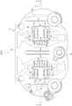
Fig. 2] Fig. 2 is a plan view illustrating a vehicular disc brake according to an embodiment of the invention. - [
Fig. 3] Fig. 3 is a back view illustrating the vehicular disc brake according to the embodiment of the invention. - [
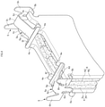
Fig. 4] Fig. 4 is a perspective view illustrating a turn-in side pad spring, a turn-out side pad spring, and friction pads according to the embodiment of the invention. -
Fig. 1 to Fig. 4 illustrate a vehicular disc brake according to an embodiment of the invention. It should be noted here that arrow A represents the rotational direction of a disc rotor that rotates together with a wheel when the vehicle moves forward and a disc turn-out side and a disc turn-in side described below assume that the vehicle moves forward. - A
vehicular disc brake 1 according to the embodiment includes adisc rotor 2 that rotates together with a wheel, acaliper body 3 attached to a vehicle body in one side portion of thedisc rotor 2,friction pads disc rotor 2 sandwiched therebetween betweenaction portions caliper body 3 disposed in both side portions of thedisc rotor 2, a turn-inside pad spring 5 biasing thefriction pads side pad spring 6 biasing thefriction pads 4 toward the disc radial inner side. - The
caliper body 3 integrally has the pair ofaction portions bridge portion 3b on the disc turn-in side, abridge portion 3c on the disc turn-out side, and abridge portion 3d in the middle portion in the disc circumferential direction that connect the pair ofaction portions ceiling opening 3e on disc turn-in side is formed between thebridge portion 3b on the disc turn-in side and thebridge portion 3d in the middle portion in the disc circumferential direction and a ceiling opening 3f on the disc turn-out side is formed between thebridge portion 3c on the disc turn-out side and thebridge portion 3d in the middle portion in disc circumferential direction. Twocylinder holes 8 for accommodatingpistons 7 are provided so as to face each other in each of theaction portions 3a and a hydraulic chamber (not illustrated) is defined between each of thepistons 7 and each of thecylinder holes 8. - The
acting portions pad accommodating portions friction pads pad accommodating portions side surface 3h of the ceiling opening 3e on the disc turn-in side and closer to the disc radial inner side than the disc turn-inside surface 3h and a turn-out sidetorque reception surface 3k formed in a position closer to the inside of the caliper body than a disc turn-outside surface 3j of the ceiling opening 3f on the disc turn-out side and close to the disc radial inner side, and a turn-in side torque reception steppedportion 3m is formed between the disc turn-inside surface 3h and the turn-in side torque reception surface 3i and a turn-out side torque reception steppedportion 3n is formed between the disc turn-outside surface 3j and the turn-out sidetorque reception surface 3k. - The disc radial inner side surface in the middle portion in the disc shaft direction of the
bridge portion 3b on the disc turn-in side is provided with a turn-in side attachment recessedportion 3p to which the turn-inside pad spring 5 is attached and the disc radial inner side surface in the middle portion in the disc shaft direction of thebridge portion 3c on the disc turn-out side is provided with a turn-out side attachment recessed portion 3q to which the turn-outside pad spring 6 is attached. - Each of the
friction pads 4 includes alining 4a in slidable contact with the side surface of thedisc rotor 2 and aback plate 4b of metal to which thelining 4a is pasted andear pieces back plate 4b. Furthermore, a pair of projectingpieces outer side surface 4d of theback plate 4b and thefriction pads - The turn-in
side pad spring 5 is attached to the turn-in side attachment recessedportion 3p formed in thebridge portion 3b on the disc turn-in side and has a turn-in sideresilient portion 5a biasing thefriction pads side retainer portion 5b laid on the turn-in side torque reception steppedportion 3m. - The turn-in side
resilient portion 5a has a turn-inside attachment portion 5c formed by convexly bending a zonal member so as to be engageable with the turn-in side attachment recessedportion 3p, a turn-inside extending piece 5d extending to the disc radial outer side of thefriction pads side attachment portion 5c, and a turn-in sideresilient piece 5g folded from the projecting end portion of the turn-inside extending piece 5d toward the friction pads via acurved portion 5e so that anend portion 5f thereof makes contact with the disc turn-in side surfaces of the projectingpieces resilient portion 5a further has a pair of turn-inside holding pieces side extending piece 5d, make contact with the disc turn-inside surface 3h of thebridge portion 3b on the disc turn-in side, and extend to the disc radial outer side of the turn-in sideresilient portion 5a and the turn-inside retainer portions portions side holding pieces - The turn-out
side pad spring 6 has a turn-out sideresilient portion 6a that is attached to the turn-out side attachment recessed portion 3q formed in thebridge portion 3c on the disc turn-out side and biases thefriction pads side retainer portion 6b laid on the turn-out side torque reception steppedportion 3n. - The turn-out side
resilient portion 6a has a turn-outside attachment portion 6c formed by convexly bending a zonal member so as to be engageable with the turn-out side attachment recessed portion 3q, a turn-outside extending piece 6d extending to the disc radial outer side of thefriction pads side attachment portion 6c, and a turn-out sideresilient piece 6g folded from the projecting end portion of the turn-outside extending piece 6d toward the friction pads via acurved portion 6e so that anend portion 6f thereof makes contact with the disc radialouter side surfaces back plates resilient portion 6a further has a pair of turn-outside holding pieces side extending piece 6d, make contact with the disc turn-outside surface 3j of thebridge portion 3c on the disc turn-out side, and extend to the disc radial outer side of the turn-out sideresilient portion 6a and the turn-outside retainer portions portions side holding pieces - The
friction pads side pad spring 5, and the turn-outside pad spring 6 formed as described above are assembled by first engaging the turn-inside attachment portion 5c of the turn-inside pad spring 5 with the turn-in side attachment recessedportion 3p, bringing the turn-inside holding pieces side surface 3h of the ceiling opening 3e on the disc turn-in side, laying the turn-inside retainer portions portions side attachment portion 6c of the turn-outside pad spring 6 with the turn-out side attachment recessed portion 3q, bringing the turn-outside holding pieces side surface 3j of the ceiling opening 3f on the disc turn-out side, laying the turn-outside retainer portions portions portion 3m and the turn-out side torque reception steppedportion 3n to support theear pieces friction pads side retainer portion 5b and the turn-outside retainer portion 6b. - This assembly causes the
friction pads portion 3m and the turn-out side torque reception steppedportion 3n via theear pieces torque reception surface 3k, the turn-in side torque reception steppedportion 3m, and the turn-out side torque reception steppedportion 3n. In addition, since theend portion 5f of the turn-in sideresilient piece 5g of the turn-inside pad spring 5 makes contact with the disc turn-in side surfaces of the projectingpieces friction pads 4 and theend portion 6f of the turn-out sideresilient piece 6g of the turn-outside pad spring 6 makes contact with the disc radialouter side surfaces friction pads 4, thefriction pads side pad spring 5 and biased to the disc radial inner side by the turn-outside pad spring 6. - Since the turn-in side
resilient piece 5g of the turn-inside pad spring 5 and the turn-out sideresilient piece 6g of the turn-outside pad spring 6 bias thefriction pads friction pads resilient piece 5g biases thefriction pads side surface 4f of theback plate 4b is in contact with the turn-out sidetorque reception surface 3k in advance, the rattling of thefriction pads side retainer portion 5b of the turn-inside pad spring 5 and the turn-outside retainer portion 6b of the turn-outside pad spring 6 move thefriction pads portion 3m and the turn-out side torque reception steppedportion 3n of thecaliper body 3 can be suppressed. - In addition, since the turn-in
side pad spring 5 is attached to the disc turn-in side of the frictionpad accommodating portion 3g of thebridge portion 3b on the disc turn-in side and the turn-outside pad spring 6 is attached to the disc turn-out side of the friction pad accommodating portion of thebridge portion 3c on the disc turn-out side, the clearance between thebridge portion 3d in the middle portion in the disc circumferential direction and thefriction pads caliper body 3 is increased. In addition, since the turn-inside pad spring 5 and the turn-outside pad spring 6 are attached so that the turn-inside pad spring 5 is engaged with the turn-in side attachment recessedportion 3p formed in thebridge portion 3b on the disc turn-in side and the turn-outside pad spring 6 is engaged with the turn-out side attachment recessed portion 3q formed in thebridge portion 3c on the disc turn-out side, respectively, the turn-inside pad spring 5 and the turn-outside pad spring 6 can be attached without increasing the thicknesses of thebridge portions caliper body 3 is increased. - Since the
friction pads friction pads side pad spring 5 makes contact with the disc turn-inside surface 3h of theceiling opening 3e and has the turn-inside holding piece 5h extending to the disc radial outer side of the turn-in sideresilient portion 5a, and the turn-outside pad spring 6 makes contact with the disc turn-outside surface 3j of the ceiling opening 3f and has the turn-outside holding piece 6h extending to the disc radial outer side of the turn-out sideresilient piece 6g. Accordingly, when thefriction pads side pad spring 5 and the turn-outside pad spring 6 are assembled to thecaliper body 3, the turn-inside pad spring 5 and the turn-outside pad spring 6 can be held in a stable state, thereby improving assemblability. - It should be noted here that the invention is not limited to the above embodiment in which the friction pads are formed symmetrically with respect to the center line CL extending in the disc radial direction and the projecting pieces with which the turn-in side resilient piece of the turn-in side pad spring makes contact may be provided only on the disc turn-in side and, in this case, the turn-in side pad spring and the turn-out side pad spring can be formed in the same shape. In addition, the ceiling opening may be formed in any shape and the bridge portion may have only one ceiling opening. In addition, the invention is applicable to a 2-pot opposed-piston caliper body and an opposed-piston caliper body with six or more pots and also applicable to a separate type caliper body in addition to an integral type caliper body.
-
- 1:
- vehicular disc brake
- 2:
- disc rotor
- 3:
- caliper body
- 3a:
- action portion
- 3b, 3c, 3d:
- bridge portion
- 3e, 3f:
- ceiling opening
- 3g:
- friction pad accommodating portion
- 3h:
- disc turn-in side surface
- 3i:
- turn-in side torque reception surface
- 3j:
- disc turn-out side surface
- 3k:
- turn-out side torque reception surface
- 3m:
- turn-in side torque reception stepped portion
- 3n:
- turn-out side torque reception stepped portion
- 3p:
- turn-in side attachment recessed portion
- 3q:
- turn-out side attachment recessed portion
- 4:
- friction pad
- 4a:
- lining
- 4b:
- back plate
- 4c:
- ear piece
- 4d:
- disc radial outer side surface
- 4e:
- projecting piece
- 4f:
- disc turn-out side surface
- 5:
- turn-in side pad spring
- 5a:
- turn-in side resilient portion
- 5b:
- turn-in side retainer portion
- 5c:
- turn-in side attachment portion
- 5d:
- turn-in side extending piece
- 5e:
- curved portion
- 5f:
- end portion
- 5g:
- turn-in side resilient piece
- 5h:
- turn-in side holding piece
- 6:
- turn-out side pad spring
- 6a:
- turn-out side resilient portion
- 6b:
- turn-out side retainer portion
- 6c:
- turn-out side attachment portion
- 6d:
- turn-out side extending piece
- 6e:
- curved portion
- 6f:
- end portion
- 6g:
- turn-out side resilient piece
- 6h:
- turn-out side holding piece
- 7:
- piston
- 8:
- cylinder hole
Claims (3)
- A vehicular disc brake (1),
in which a caliper body (3) is formed by connecting, via a bridge portion (3b, 3c, 3d) straddling an outer periphery of a disc rotor (2), a pair of action portions (3a) facing each other with the disc rotor (2) sandwiched therebetween, the action portions (3a) are provided with a pair of friction pad accommodating portions (3g) that accommodate a pair of friction pads (4) disposed with the disc rotor (2) sandwiched therebetween, ear pieces (4c) project on a disc turn-in side and a disc turn-out side in vehicle forward movement on a disc radial outer side of each of the friction pads (4), and torque reception stepped portions (3m, 3n) are formed on the disc radial outer side of each of the friction pad accommodating portions (3g), the torque reception stepped portions (3m, 3n) supporting the ear pieces (4c) so that the ear pieces (4c) are movable in a disc shaft direction,
characterized by:- a turn-in side pad spring (5) that has a turn-in side resilient portion (5a) attached to a part of the bridge portion (3b, 3c, 3d) on the disc turn-in side in vehicle forward movement of the friction pad accommodating portions (3g), the turn-in side resilient portion (5a) biasing the friction pads (4) to a disc radial inner side and the disc turn-out side, and a turn-in side retainer portion (5b) laid on one of the torque reception stepped portions (3m, 3n) on the disc turn-in side; and- a turn-out side pad spring (6) that has a turn-out side resilient portion (6a) attached to a part of the bridge portion (3b, 3c, 3d) on the disc turn-out side in vehicle forward movement of the friction pad accommodating portions (3g), the turn-out side resilient portion (6a) biasing the friction pads (4) to the disc radial inner side, and a turn-out side retainer portion (6b) laid on the other of the torque reception stepped portions (3m, 3n) on the disc turn-out side. - The vehicular disc brake (1) according to claim 1, wherein- each of the friction pads (4) has a pair of projecting pieces (4e) projecting toward the disc radial outer side on the disc radial outer surface, the friction pads (4) being formed symmetrically with respect to a center line (CL) extending in a disc radial direction,- the turn-in side resilient portion (5a) has a turn-in side attachment portion (5c) to be attached to a disc radial inner side surface of the bridge portion (3b, 3c, 3d), a turn-in side extending piece (5d) extending to the disc radial outer side of the friction pads (4) from the turn-in side attachment portion (5c), and a turn-in side resilient piece (5g) that is folded toward the friction pads (4) via a curved portion (5e) from a projecting end portion of the turn-in side extending piece (5d) and has an end portion (5f) in contact with disc turn-in side surfaces of the projecting pieces (4e) on the disc turn-in side, and- the turn-out side resilient portion (6a) has a turn-out side attachment portion (6c) to be attached to the disc radial inner side surface of the bridge portion (3b, 3c, 3d), a turn-out side extending piece (6d) extending to the disc radial outer side of the friction pads (4) from the turn-out side attachment portion (6c), and a turn-out side resilient piece (6g) that is folded toward the friction pads (4) via a curved portion (6e) from a projecting end portion of the turn-out side extending piece and has an end portion (6f) in contact with the disc radial outer side surfaces of the friction pads (4).
- The vehicular disc brake (1) according to claim 1 or 2, wherein- the bridge portion (3b, 3c, 3d) is provided with a ceiling opening (3e, 3f), the friction pad accommodating portions (3g) are formed on the disc radial inner side of the ceiling opening (3e, 3f),- the turn-in side pad spring (5) has a turn-in side holding piece (5h) that makes contact with a disc turn-in side surface of the ceiling opening (3e, 3f) and extends to the disc radial outer side of the turn-in side resilient portion (5a) and the turn-in side retainer portion (5b) is formed on the disc radial inner side of the turn-in side holding piece (5h), and- the turn-out side pad spring (6) has a turn-out side holding piece (6h) that makes contact with a disc turn-out side surface of the ceiling opening (3e, 3f) and extends to the disc radial outer side of the turn-out side resilient portion (6a) and the turn-out side retainer portion (6b) is formed on the disc radial inner side of the turn-out side holding piece (6h).
Applications Claiming Priority (2)
| Application Number | Priority Date | Filing Date | Title |
|---|---|---|---|
| JP2017172058 | 2017-09-07 | ||
| PCT/JP2018/027829 WO2019049539A1 (en) | 2017-09-07 | 2018-07-25 | Vehicular disc brake |
Publications (3)
| Publication Number | Publication Date |
|---|---|
| EP3680504A1 EP3680504A1 (en) | 2020-07-15 |
| EP3680504A4 EP3680504A4 (en) | 2021-03-17 |
| EP3680504B1 true EP3680504B1 (en) | 2022-02-09 |
Family
ID=65633921
Family Applications (1)
| Application Number | Title | Priority Date | Filing Date |
|---|---|---|---|
| EP18854384.7A Active EP3680504B1 (en) | 2017-09-07 | 2018-07-25 | Vehicular disc brake |
Country Status (6)
| Country | Link |
|---|---|
| US (1) | US11287000B2 (en) |
| EP (1) | EP3680504B1 (en) |
| JP (1) | JP6917464B2 (en) |
| CN (1) | CN110945261B (en) |
| ES (1) | ES2907701T3 (en) |
| WO (1) | WO2019049539A1 (en) |
Families Citing this family (5)
| Publication number | Priority date | Publication date | Assignee | Title |
|---|---|---|---|---|
| JP7576393B2 (en) * | 2019-09-27 | 2024-10-31 | 日立Astemo株式会社 | Vehicle disc brakes |
| JP2021063527A (en) * | 2019-10-11 | 2021-04-22 | 日信工業株式会社 | Caliper body of disk brake for vehicle |
| CN115956169B (en) * | 2020-08-25 | 2025-10-03 | 本田技研工业株式会社 | Disc brakes |
| IT202100000743A1 (en) * | 2021-01-18 | 2022-07-18 | Brembo Spa | RIBBON SPRING AND SPRING RIBBON AND BRAKE PAD ASSEMBLY |
| IT202100000749A1 (en) * | 2021-01-18 | 2022-07-18 | Brembo Spa | RIBBON SPRING AND SPRING RIBBON AND BRAKE PAD ASSEMBLY |
Citations (5)
| Publication number | Priority date | Publication date | Assignee | Title |
|---|---|---|---|---|
| US4498564A (en) | 1981-09-18 | 1985-02-12 | Tokico Ltd. | Disc brake subassembly having friction pad retaining means |
| EP2775159A1 (en) | 2013-03-06 | 2014-09-10 | Hitachi Automotive Systems, Ltd. | Disc brake |
| EP2775160A1 (en) | 2013-03-06 | 2014-09-10 | Hitachi Automotive Systems, Ltd. | Disc brake |
| JP2014214815A (en) | 2013-04-25 | 2014-11-17 | 日立オートモティブシステムズ株式会社 | Disc brake |
| JP2016011742A (en) | 2014-06-30 | 2016-01-21 | 日立オートモティブシステムズ株式会社 | Disc brake |
Family Cites Families (16)
| Publication number | Priority date | Publication date | Assignee | Title |
|---|---|---|---|---|
| JP2552633Y2 (en) | 1992-03-27 | 1997-10-29 | トキコ株式会社 | Disc brake |
| FR2800140B1 (en) * | 1999-10-26 | 2002-01-11 | Bosch Gmbh Robert | FRICTION ELEMENTS GUIDING SPRING AND DISC BRAKE COMPRISING AT LEAST ONE SUCH SPRING |
| DE10233446A1 (en) * | 2002-07-24 | 2004-02-12 | Continental Teves Ag & Co. Ohg | Brake holder of floating calliper disc brake for motor vehicles has brake pad guide spring fitted radially on brake holder and locked thereupon by means of at least one retaining clip both radially and axially |
| US7318503B2 (en) * | 2004-04-26 | 2008-01-15 | Akebono Corporation (North America) | Pad retaining clips |
| JP2006194312A (en) * | 2005-01-12 | 2006-07-27 | Advics:Kk | Disc brake |
| DE102009007201A1 (en) * | 2008-03-28 | 2009-10-01 | Continental Teves Ag & Co. Ohg | Disk brake i.e. floating caliper disk brake, for use in motor vehicle brake system, has spring arrangement with radial spring element, which is designed such that assembly of element is enabled when brake lining is mounted |
| US8469159B2 (en) * | 2010-06-07 | 2013-06-25 | GM Global Technology Operations LLC | Brake assembly |
| US8393441B2 (en) * | 2011-01-24 | 2013-03-12 | Akebono Brake Corporation | Spreader spring |
| JP2012180905A (en) * | 2011-03-02 | 2012-09-20 | Nissin Kogyo Co Ltd | Vehicle disc brake |
| JP5855606B2 (en) * | 2013-06-18 | 2016-02-09 | 日信工業株式会社 | Vehicle disc brake |
| CN203685939U (en) * | 2013-12-17 | 2014-07-02 | 比亚迪股份有限公司 | Braking plate for vehicles and vehicles with braking plate |
| JP2016050601A (en) * | 2014-08-29 | 2016-04-11 | 日信工業株式会社 | Vehicular disk brake |
| DE102014014081A1 (en) * | 2014-09-23 | 2016-03-24 | Lucas Automotive Gmbh | Guide means for a brake pad assembly of a disc brake and disc brake |
| CN106715945B (en) * | 2014-11-19 | 2019-03-08 | 日立汽车系统株式会社 | Disc brakes |
| KR20160141435A (en) * | 2015-06-01 | 2016-12-09 | 주식회사 만도 | Disc brake |
| CN206468717U (en) * | 2017-01-23 | 2017-09-05 | 长城汽车股份有限公司 | Disk brake yoke spring structure |
-
2018
- 2018-07-25 ES ES18854384T patent/ES2907701T3/en active Active
- 2018-07-25 CN CN201880047118.6A patent/CN110945261B/en active Active
- 2018-07-25 JP JP2019540814A patent/JP6917464B2/en active Active
- 2018-07-25 US US16/644,617 patent/US11287000B2/en active Active
- 2018-07-25 EP EP18854384.7A patent/EP3680504B1/en active Active
- 2018-07-25 WO PCT/JP2018/027829 patent/WO2019049539A1/en not_active Ceased
Patent Citations (5)
| Publication number | Priority date | Publication date | Assignee | Title |
|---|---|---|---|---|
| US4498564A (en) | 1981-09-18 | 1985-02-12 | Tokico Ltd. | Disc brake subassembly having friction pad retaining means |
| EP2775159A1 (en) | 2013-03-06 | 2014-09-10 | Hitachi Automotive Systems, Ltd. | Disc brake |
| EP2775160A1 (en) | 2013-03-06 | 2014-09-10 | Hitachi Automotive Systems, Ltd. | Disc brake |
| JP2014214815A (en) | 2013-04-25 | 2014-11-17 | 日立オートモティブシステムズ株式会社 | Disc brake |
| JP2016011742A (en) | 2014-06-30 | 2016-01-21 | 日立オートモティブシステムズ株式会社 | Disc brake |
Also Published As
| Publication number | Publication date |
|---|---|
| US11287000B2 (en) | 2022-03-29 |
| WO2019049539A1 (en) | 2019-03-14 |
| JPWO2019049539A1 (en) | 2020-08-20 |
| US20210079968A1 (en) | 2021-03-18 |
| EP3680504A4 (en) | 2021-03-17 |
| JP6917464B2 (en) | 2021-08-11 |
| CN110945261B (en) | 2021-03-23 |
| EP3680504A1 (en) | 2020-07-15 |
| ES2907701T3 (en) | 2022-04-26 |
| CN110945261A (en) | 2020-03-31 |
Similar Documents
| Publication | Publication Date | Title |
|---|---|---|
| EP3680504B1 (en) | Vehicular disc brake | |
| JP6189718B2 (en) | Disc brake pad and disc brake device | |
| JP5855397B2 (en) | Disc brake pad assembly | |
| JP6261289B2 (en) | Disc brake pad spring | |
| EP3153736B1 (en) | Pad assembly for disk brake | |
| US9759277B2 (en) | Shim assembly for disk brake | |
| EP2757281A1 (en) | Pad assembly for disk brake | |
| JP4698147B2 (en) | Disc brake assembly | |
| US11959522B2 (en) | Brake assembly | |
| JP2023089292A (en) | disc brake and cover parts | |
| US11162550B2 (en) | Caliper for opposed piston type disc brake | |
| US11320011B2 (en) | Caliper for opposed piston-type disc brake | |
| JP2022024201A (en) | Disc brakes, friction pads and shims | |
| EP3575624A1 (en) | Disc brake pad and disc brake device | |
| JP5544263B2 (en) | Brake pads | |
| JP5603797B2 (en) | Vehicle disc brake | |
| US12270442B2 (en) | Pad clip for disc brake apparatus and disc brake apparatus | |
| WO2024135576A1 (en) | Opposed piston-type disc brake device | |
| JP5171797B2 (en) | Vehicle disc brake | |
| JP2014126066A (en) | Disk brake for vehicle | |
| JP6113494B2 (en) | Vehicle disc brake | |
| JP2011033130A (en) | Disc brake |
Legal Events
| Date | Code | Title | Description |
|---|---|---|---|
| STAA | Information on the status of an ep patent application or granted ep patent |
Free format text: STATUS: THE INTERNATIONAL PUBLICATION HAS BEEN MADE |
|
| PUAI | Public reference made under article 153(3) epc to a published international application that has entered the european phase |
Free format text: ORIGINAL CODE: 0009012 |
|
| STAA | Information on the status of an ep patent application or granted ep patent |
Free format text: STATUS: REQUEST FOR EXAMINATION WAS MADE |
|
| 17P | Request for examination filed |
Effective date: 20191120 |
|
| AK | Designated contracting states |
Kind code of ref document: A1 Designated state(s): AL AT BE BG CH CY CZ DE DK EE ES FI FR GB GR HR HU IE IS IT LI LT LU LV MC MK MT NL NO PL PT RO RS SE SI SK SM TR |
|
| AX | Request for extension of the european patent |
Extension state: BA ME |
|
| RIN1 | Information on inventor provided before grant (corrected) |
Inventor name: SASAKI, YUKI Inventor name: TEZUKA, TOSHIHIRO |
|
| DAV | Request for validation of the european patent (deleted) | ||
| DAX | Request for extension of the european patent (deleted) | ||
| A4 | Supplementary search report drawn up and despatched |
Effective date: 20210211 |
|
| RIC1 | Information provided on ipc code assigned before grant |
Ipc: F16D 55/228 20060101ALI20210205BHEP Ipc: F16D 65/097 20060101AFI20210205BHEP |
|
| GRAP | Despatch of communication of intention to grant a patent |
Free format text: ORIGINAL CODE: EPIDOSNIGR1 |
|
| STAA | Information on the status of an ep patent application or granted ep patent |
Free format text: STATUS: GRANT OF PATENT IS INTENDED |
|
| RIC1 | Information provided on ipc code assigned before grant |
Ipc: F16D 55/228 20060101ALI20211006BHEP Ipc: F16D 65/097 20060101AFI20211006BHEP |
|
| INTG | Intention to grant announced |
Effective date: 20211026 |
|
| GRAS | Grant fee paid |
Free format text: ORIGINAL CODE: EPIDOSNIGR3 |
|
| GRAA | (expected) grant |
Free format text: ORIGINAL CODE: 0009210 |
|
| STAA | Information on the status of an ep patent application or granted ep patent |
Free format text: STATUS: THE PATENT HAS BEEN GRANTED |
|
| RIN1 | Information on inventor provided before grant (corrected) |
Inventor name: TEZUKA, TOSHIHIRO Inventor name: SASAKI, YUKI |
|
| RAP1 | Party data changed (applicant data changed or rights of an application transferred) |
Owner name: HITACHI ASTEMO, LTD. |
|
| AK | Designated contracting states |
Kind code of ref document: B1 Designated state(s): AL AT BE BG CH CY CZ DE DK EE ES FI FR GB GR HR HU IE IS IT LI LT LU LV MC MK MT NL NO PL PT RO RS SE SI SK SM TR |
|
| REG | Reference to a national code |
Ref country code: GB Ref legal event code: FG4D |
|
| REG | Reference to a national code |
Ref country code: CH Ref legal event code: EP Ref country code: AT Ref legal event code: REF Ref document number: 1467693 Country of ref document: AT Kind code of ref document: T Effective date: 20220215 |
|
| REG | Reference to a national code |
Ref country code: IE Ref legal event code: FG4D |
|
| REG | Reference to a national code |
Ref country code: DE Ref legal event code: R096 Ref document number: 602018030742 Country of ref document: DE |
|
| REG | Reference to a national code |
Ref country code: ES Ref legal event code: FG2A Ref document number: 2907701 Country of ref document: ES Kind code of ref document: T3 Effective date: 20220426 |
|
| REG | Reference to a national code |
Ref country code: LT Ref legal event code: MG9D |
|
| REG | Reference to a national code |
Ref country code: NL Ref legal event code: MP Effective date: 20220209 |
|
| REG | Reference to a national code |
Ref country code: AT Ref legal event code: MK05 Ref document number: 1467693 Country of ref document: AT Kind code of ref document: T Effective date: 20220209 |
|
| PG25 | Lapsed in a contracting state [announced via postgrant information from national office to epo] |
Ref country code: SE Free format text: LAPSE BECAUSE OF FAILURE TO SUBMIT A TRANSLATION OF THE DESCRIPTION OR TO PAY THE FEE WITHIN THE PRESCRIBED TIME-LIMIT Effective date: 20220209 Ref country code: RS Free format text: LAPSE BECAUSE OF FAILURE TO SUBMIT A TRANSLATION OF THE DESCRIPTION OR TO PAY THE FEE WITHIN THE PRESCRIBED TIME-LIMIT Effective date: 20220209 Ref country code: PT Free format text: LAPSE BECAUSE OF FAILURE TO SUBMIT A TRANSLATION OF THE DESCRIPTION OR TO PAY THE FEE WITHIN THE PRESCRIBED TIME-LIMIT Effective date: 20220609 Ref country code: NO Free format text: LAPSE BECAUSE OF FAILURE TO SUBMIT A TRANSLATION OF THE DESCRIPTION OR TO PAY THE FEE WITHIN THE PRESCRIBED TIME-LIMIT Effective date: 20220509 Ref country code: NL Free format text: LAPSE BECAUSE OF FAILURE TO SUBMIT A TRANSLATION OF THE DESCRIPTION OR TO PAY THE FEE WITHIN THE PRESCRIBED TIME-LIMIT Effective date: 20220209 Ref country code: LT Free format text: LAPSE BECAUSE OF FAILURE TO SUBMIT A TRANSLATION OF THE DESCRIPTION OR TO PAY THE FEE WITHIN THE PRESCRIBED TIME-LIMIT Effective date: 20220209 Ref country code: HR Free format text: LAPSE BECAUSE OF FAILURE TO SUBMIT A TRANSLATION OF THE DESCRIPTION OR TO PAY THE FEE WITHIN THE PRESCRIBED TIME-LIMIT Effective date: 20220209 Ref country code: BG Free format text: LAPSE BECAUSE OF FAILURE TO SUBMIT A TRANSLATION OF THE DESCRIPTION OR TO PAY THE FEE WITHIN THE PRESCRIBED TIME-LIMIT Effective date: 20220509 |
|
| PG25 | Lapsed in a contracting state [announced via postgrant information from national office to epo] |
Ref country code: PL Free format text: LAPSE BECAUSE OF FAILURE TO SUBMIT A TRANSLATION OF THE DESCRIPTION OR TO PAY THE FEE WITHIN THE PRESCRIBED TIME-LIMIT Effective date: 20220209 Ref country code: LV Free format text: LAPSE BECAUSE OF FAILURE TO SUBMIT A TRANSLATION OF THE DESCRIPTION OR TO PAY THE FEE WITHIN THE PRESCRIBED TIME-LIMIT Effective date: 20220209 Ref country code: GR Free format text: LAPSE BECAUSE OF FAILURE TO SUBMIT A TRANSLATION OF THE DESCRIPTION OR TO PAY THE FEE WITHIN THE PRESCRIBED TIME-LIMIT Effective date: 20220510 Ref country code: FI Free format text: LAPSE BECAUSE OF FAILURE TO SUBMIT A TRANSLATION OF THE DESCRIPTION OR TO PAY THE FEE WITHIN THE PRESCRIBED TIME-LIMIT Effective date: 20220209 Ref country code: AT Free format text: LAPSE BECAUSE OF FAILURE TO SUBMIT A TRANSLATION OF THE DESCRIPTION OR TO PAY THE FEE WITHIN THE PRESCRIBED TIME-LIMIT Effective date: 20220209 |
|
| PG25 | Lapsed in a contracting state [announced via postgrant information from national office to epo] |
Ref country code: IS Free format text: LAPSE BECAUSE OF FAILURE TO SUBMIT A TRANSLATION OF THE DESCRIPTION OR TO PAY THE FEE WITHIN THE PRESCRIBED TIME-LIMIT Effective date: 20220609 |
|
| PG25 | Lapsed in a contracting state [announced via postgrant information from national office to epo] |
Ref country code: SM Free format text: LAPSE BECAUSE OF FAILURE TO SUBMIT A TRANSLATION OF THE DESCRIPTION OR TO PAY THE FEE WITHIN THE PRESCRIBED TIME-LIMIT Effective date: 20220209 Ref country code: SK Free format text: LAPSE BECAUSE OF FAILURE TO SUBMIT A TRANSLATION OF THE DESCRIPTION OR TO PAY THE FEE WITHIN THE PRESCRIBED TIME-LIMIT Effective date: 20220209 Ref country code: RO Free format text: LAPSE BECAUSE OF FAILURE TO SUBMIT A TRANSLATION OF THE DESCRIPTION OR TO PAY THE FEE WITHIN THE PRESCRIBED TIME-LIMIT Effective date: 20220209 Ref country code: EE Free format text: LAPSE BECAUSE OF FAILURE TO SUBMIT A TRANSLATION OF THE DESCRIPTION OR TO PAY THE FEE WITHIN THE PRESCRIBED TIME-LIMIT Effective date: 20220209 Ref country code: DK Free format text: LAPSE BECAUSE OF FAILURE TO SUBMIT A TRANSLATION OF THE DESCRIPTION OR TO PAY THE FEE WITHIN THE PRESCRIBED TIME-LIMIT Effective date: 20220209 Ref country code: CZ Free format text: LAPSE BECAUSE OF FAILURE TO SUBMIT A TRANSLATION OF THE DESCRIPTION OR TO PAY THE FEE WITHIN THE PRESCRIBED TIME-LIMIT Effective date: 20220209 |
|
| REG | Reference to a national code |
Ref country code: DE Ref legal event code: R026 Ref document number: 602018030742 Country of ref document: DE |
|
| PLBI | Opposition filed |
Free format text: ORIGINAL CODE: 0009260 |
|
| PLAX | Notice of opposition and request to file observation + time limit sent |
Free format text: ORIGINAL CODE: EPIDOSNOBS2 |
|
| PG25 | Lapsed in a contracting state [announced via postgrant information from national office to epo] |
Ref country code: AL Free format text: LAPSE BECAUSE OF FAILURE TO SUBMIT A TRANSLATION OF THE DESCRIPTION OR TO PAY THE FEE WITHIN THE PRESCRIBED TIME-LIMIT Effective date: 20220209 |
|
| 26 | Opposition filed |
Opponent name: VRI-VERBAND DER REIBBELAGINDUSTRIE E.V. Effective date: 20221104 |
|
| PG25 | Lapsed in a contracting state [announced via postgrant information from national office to epo] |
Ref country code: SI Free format text: LAPSE BECAUSE OF FAILURE TO SUBMIT A TRANSLATION OF THE DESCRIPTION OR TO PAY THE FEE WITHIN THE PRESCRIBED TIME-LIMIT Effective date: 20220209 Ref country code: MC Free format text: LAPSE BECAUSE OF FAILURE TO SUBMIT A TRANSLATION OF THE DESCRIPTION OR TO PAY THE FEE WITHIN THE PRESCRIBED TIME-LIMIT Effective date: 20220209 |
|
| REG | Reference to a national code |
Ref country code: CH Ref legal event code: PL |
|
| REG | Reference to a national code |
Ref country code: BE Ref legal event code: MM Effective date: 20220731 |
|
| PLBB | Reply of patent proprietor to notice(s) of opposition received |
Free format text: ORIGINAL CODE: EPIDOSNOBS3 |
|
| PG25 | Lapsed in a contracting state [announced via postgrant information from national office to epo] |
Ref country code: LU Free format text: LAPSE BECAUSE OF NON-PAYMENT OF DUE FEES Effective date: 20220725 Ref country code: LI Free format text: LAPSE BECAUSE OF NON-PAYMENT OF DUE FEES Effective date: 20220731 Ref country code: FR Free format text: LAPSE BECAUSE OF NON-PAYMENT OF DUE FEES Effective date: 20220731 Ref country code: CH Free format text: LAPSE BECAUSE OF NON-PAYMENT OF DUE FEES Effective date: 20220731 |
|
| PG25 | Lapsed in a contracting state [announced via postgrant information from national office to epo] |
Ref country code: BE Free format text: LAPSE BECAUSE OF NON-PAYMENT OF DUE FEES Effective date: 20220731 |
|
| PG25 | Lapsed in a contracting state [announced via postgrant information from national office to epo] |
Ref country code: IE Free format text: LAPSE BECAUSE OF NON-PAYMENT OF DUE FEES Effective date: 20220725 |
|
| PG25 | Lapsed in a contracting state [announced via postgrant information from national office to epo] |
Ref country code: MK Free format text: LAPSE BECAUSE OF FAILURE TO SUBMIT A TRANSLATION OF THE DESCRIPTION OR TO PAY THE FEE WITHIN THE PRESCRIBED TIME-LIMIT Effective date: 20220209 Ref country code: CY Free format text: LAPSE BECAUSE OF FAILURE TO SUBMIT A TRANSLATION OF THE DESCRIPTION OR TO PAY THE FEE WITHIN THE PRESCRIBED TIME-LIMIT Effective date: 20220209 |
|
| PG25 | Lapsed in a contracting state [announced via postgrant information from national office to epo] |
Ref country code: HU Free format text: LAPSE BECAUSE OF FAILURE TO SUBMIT A TRANSLATION OF THE DESCRIPTION OR TO PAY THE FEE WITHIN THE PRESCRIBED TIME-LIMIT; INVALID AB INITIO Effective date: 20180725 |
|
| REG | Reference to a national code |
Ref country code: DE Ref legal event code: R100 Ref document number: 602018030742 Country of ref document: DE |
|
| PLCK | Communication despatched that opposition was rejected |
Free format text: ORIGINAL CODE: EPIDOSNREJ1 |
|
| PG25 | Lapsed in a contracting state [announced via postgrant information from national office to epo] |
Ref country code: TR Free format text: LAPSE BECAUSE OF FAILURE TO SUBMIT A TRANSLATION OF THE DESCRIPTION OR TO PAY THE FEE WITHIN THE PRESCRIBED TIME-LIMIT Effective date: 20220209 |
|
| PG25 | Lapsed in a contracting state [announced via postgrant information from national office to epo] |
Ref country code: MT Free format text: LAPSE BECAUSE OF FAILURE TO SUBMIT A TRANSLATION OF THE DESCRIPTION OR TO PAY THE FEE WITHIN THE PRESCRIBED TIME-LIMIT Effective date: 20220209 |
|
| PLBN | Opposition rejected |
Free format text: ORIGINAL CODE: 0009273 |
|
| STAA | Information on the status of an ep patent application or granted ep patent |
Free format text: STATUS: OPPOSITION REJECTED |
|
| 27O | Opposition rejected |
Effective date: 20240619 |
|
| PGFP | Annual fee paid to national office [announced via postgrant information from national office to epo] |
Ref country code: GB Payment date: 20250605 Year of fee payment: 8 |
|
| PGFP | Annual fee paid to national office [announced via postgrant information from national office to epo] |
Ref country code: ES Payment date: 20250801 Year of fee payment: 8 |
|
| PGFP | Annual fee paid to national office [announced via postgrant information from national office to epo] |
Ref country code: DE Payment date: 20250528 Year of fee payment: 8 |
|
| PGFP | Annual fee paid to national office [announced via postgrant information from national office to epo] |
Ref country code: IT Payment date: 20250623 Year of fee payment: 8 |
|
| REG | Reference to a national code |
Ref country code: DE Ref legal event code: R081 Ref document number: 602018030742 Country of ref document: DE Owner name: ASTEMO, LTD., HITACHINAKA-SHI, JP Free format text: FORMER OWNER: HITACHI ASTEMO, LTD., HITACHINAKA-SHI, IBARAKI, JP |