EP3680448A1 - Obturateur à mâchoires à décrochage amélioré - Google Patents
Obturateur à mâchoires à décrochage amélioré Download PDFInfo
- Publication number
- EP3680448A1 EP3680448A1 EP20150951.0A EP20150951A EP3680448A1 EP 3680448 A1 EP3680448 A1 EP 3680448A1 EP 20150951 A EP20150951 A EP 20150951A EP 3680448 A1 EP3680448 A1 EP 3680448A1
- Authority
- EP
- European Patent Office
- Prior art keywords
- ram
- lobe
- assembly according
- hang
- blowout preventer
- Prior art date
- Legal status (The legal status is an assumption and is not a legal conclusion. Google has not performed a legal analysis and makes no representation as to the accuracy of the status listed.)
- Granted
Links
- 230000006872 improvement Effects 0.000 claims description 3
- 238000007789 sealing Methods 0.000 description 16
- 238000005553 drilling Methods 0.000 description 10
- 230000000712 assembly Effects 0.000 description 4
- 238000000429 assembly Methods 0.000 description 4
- 238000013461 design Methods 0.000 description 4
- 239000012530 fluid Substances 0.000 description 4
- 230000003466 anti-cipated effect Effects 0.000 description 3
- 230000008901 benefit Effects 0.000 description 3
- 238000004519 manufacturing process Methods 0.000 description 3
- 230000000284 resting effect Effects 0.000 description 3
- 238000010586 diagram Methods 0.000 description 2
- 239000013536 elastomeric material Substances 0.000 description 2
- 239000007789 gas Substances 0.000 description 2
- VNWKTOKETHGBQD-UHFFFAOYSA-N methane Chemical compound C VNWKTOKETHGBQD-UHFFFAOYSA-N 0.000 description 2
- 238000012986 modification Methods 0.000 description 2
- 230000004048 modification Effects 0.000 description 2
- 239000004215 Carbon black (E152) Substances 0.000 description 1
- 229910000831 Steel Inorganic materials 0.000 description 1
- 229920001971 elastomer Polymers 0.000 description 1
- 239000000806 elastomer Substances 0.000 description 1
- 229930195733 hydrocarbon Natural products 0.000 description 1
- 150000002430 hydrocarbons Chemical class 0.000 description 1
- 239000007788 liquid Substances 0.000 description 1
- 239000003345 natural gas Substances 0.000 description 1
- 239000003208 petroleum Substances 0.000 description 1
- 239000003209 petroleum derivative Substances 0.000 description 1
- 230000007480 spreading Effects 0.000 description 1
- 239000010959 steel Substances 0.000 description 1
Images


Classifications
-
- E—FIXED CONSTRUCTIONS
- E21—EARTH DRILLING; MINING
- E21B—EARTH DRILLING, e.g. DEEP DRILLING; OBTAINING OIL, GAS, WATER, SOLUBLE OR MELTABLE MATERIALS OR A SLURRY OF MINERALS FROM WELLS
- E21B33/00—Sealing or packing boreholes or wells
- E21B33/02—Surface sealing or packing
- E21B33/03—Well heads; Setting-up thereof
- E21B33/06—Blow-out preventers, i.e. apparatus closing around a drill pipe, e.g. annular blow-out preventers
- E21B33/061—Ram-type blow-out preventers, e.g. with pivoting rams
- E21B33/062—Ram-type blow-out preventers, e.g. with pivoting rams with sliding rams
-
- E—FIXED CONSTRUCTIONS
- E21—EARTH DRILLING; MINING
- E21B—EARTH DRILLING, e.g. DEEP DRILLING; OBTAINING OIL, GAS, WATER, SOLUBLE OR MELTABLE MATERIALS OR A SLURRY OF MINERALS FROM WELLS
- E21B33/00—Sealing or packing boreholes or wells
- E21B33/10—Sealing or packing boreholes or wells in the borehole
- E21B33/12—Packers; Plugs
Definitions
- the present disclosure relates to blowout preventers. More specifically, the present disclosure relates to ram type blowout preventers that have improved hang off capabilities. Even more specifically, the present disclosure relates to ram type blowout preventers that have improved hang off capabilities.
- blowout preventers are an important safety "valve" for well pressure control.
- BOPs typically use elastomer packer elements for sealing around a pipe.
- some BOPs may provide hang off capability. Hang off is generally when the BOP supports the weight of that portion of the drill string below the BOP. The axial hang off load can be supported by a tool joint resting on the closed BOP. Ordinarily certain types of ram BOPs can be designed to provide hang off capability.
- a ram assembly is described that is used in a ram type blowout preventer configured to form a seal against a tubular member.
- the blowout preventer can a fixed size ram preventer a variable bore ram preventer.
- the ram assembly includes a packer assembly and a ram body.
- the packer assembly includes at least one elastomeric packer member having a substantially U-shaped face to form the seal against the tubular member.
- the ram body is configured to house said packer assembly and when actuated in a ram actuation direction towards the tubular member pushes said U-shaped face on the packer assembly against the tubular member.
- the ram body includes an upper U-shaped face generally aligned with the U-shaped face of the packer assembly and an upper centralizing lobe shaped and positioned to aid in moving the tubular member towards a central position with respect to the U-shaped faces of the packer assembly and ram body.
- the U-shaped face of the ram body and/or the upper centralizing lobe are shaped to improve hang off capacity of the preventer.
- the improvement of hang off capacity is due at least in part on a tapered section formed at an intersection of the ram body U-shaped face and the upper centralizing lobe.
- the hang-off is improved compared to an otherwise identical preventer having a semi-circular U-shaped face that intersects directly with a main front face of the upper centralizing lobe.
- the tapered section can include a planar surface that is at an angle between 5 and 90 degrees from the ram actuation direction. In some cases the angle is between 10 and 75 degrees, 15 and 60 degrees, or 20 and 45 degrees. In some embodiments the angle is about 30 degrees.
- the improvement of hang off capacity comes from the shape of the ram body U-shaped face and/or the upper centralizing lobe spreading the axial load of a tool joint over a larger area of the ram body above and adjacent to the U-shaped face of the ram body.
- ram preventer refers to a blowout preventer in which the pressure-control functions are achieved through the operation of hydraulically operated ram sets.
- variable bore ram preventer and “variable bore ram blowout preventer” refer to ram-type blowout preventers that are configured to enable sealing on two or more different pipe diameter sizes.
- pipe diameter sizes includes the international standard American Petroleum Institute (API) for steel drill-pipes for use in drilling and production operations in petroleum and natural gas industries.
- API 5DP specifies drill pipes in the following sizes: 2-3/8", 2-7/8", 3-1/2", 4", 4-1/2", 5", 5"-1/2, and 6-5/8".
- a variable bore ram preventer are configured to enable sealing over a diameter range of at least 1/2".
- variable bore ram preventers such as Cameron's VBR preventers are configured to seal on pipes with diameters that differ by 1-7/8" or more.
- hang off in the context of ram-type blowout preventers refers to when the BOP supports the weight of that portion of the drill string below the BOP.
- the axial hang off load is designed to be supported by a tool joint resting on the closed BOP.
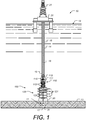
- FIG. 1 is a diagram illustrating a drilling and/or producing wellsite where sealing using a ram type preventer having improved hang off, according to some embodiments.
- an offshore drilling system is being used to drill a wellbore 11.
- the system includes an offshore vessel or platform 20 at the sea surface 12 and a subsea blowout preventer (BOP) stack assembly 100 mounted to a wellhead 30 at the sea floor 13.
- the platform 20 is equipped with a derrick 21 that supports a hoist (not shown).
- a tubular drilling riser 14 extends from the platform 20 to the BOP stack assembly 100. The riser 14 returns drilling fluid or mud to the platform 20 during drilling operations.
- One or more hydraulic conduit(s) 15 extend along the outside of the riser 14 from the platform 20 to the BOP stack assembly 100.
- the conduit(s) 15 supplies pressurized hydraulic fluid to the assembly 100.
- Casing 31 extends from the wellhead 30 into the subterranean wellbore 11.
- Downhole operations are carried out by a tubular string 16 (e.g., drillstring) that is supported by the derrick 21 and extends from the platform 20 through the riser 14, through the BOP stack assembly 100, and into the wellbore 11.
- a downhole tool 17 is shown connected to the lower end of the tubular string 16.
- the downhole tool 17 may comprise any suitable downhole tool(s) for drilling, completing, evaluating, and/or producing the wellbore 11 including, without limitation, drill bits, packers, cementing tools, casing or tubing running tools, testing equipment and/or perforating guns.
- the string 16, and hence the tool 17 coupled thereto may move axially, radially, and/or rotationally relative to the riser 14 and the BOP stack assembly 100.
- the BOP stack assembly 100 is mounted to the wellhead 30 and is designed and configured to control and seal the wellbore 11, thereby containing the hydrocarbon fluids (liquids and gases) therein.
- the BOP stack assembly 100 comprises a lower marine riser package (LMRP) 110 and a BOP or BOP stack 120.
- the LMRP 110 includes a riser flex joint 111, a riser adapter 112, one or more annular BOPs 113, and a pair of redundant control units or pods.
- a flow bore 115 extends through the LMRP 110 from the riser 14 at the upper end of the LMRP 110 to the connection at the lower end of the LMRP 110.
- the riser adapter 112 extends upward from the flex joint 111 and is coupled to the lower end of the riser 14.
- the flex joint 111 allows the riser adapter 112 and the riser 14 connected thereto to deflect angularly relative to the LMRP 110, while wellbore fluids flow from the wellbore 11 through the BOP stack assembly 100 into the riser 14.
- the annular BOPs 113 each include annular elastomeric sealing elements that are mechanically squeezed radially inward to seal on a tubular extending through the LMRP 110 (e.g., the string 16, casing, drillpipe, drill collar, etc.) or seal off the flow bore 115.
- the annular BOPs 113 have the ability to seal on a variety of pipe sizes and/or profiles, as well as perform a "Complete Shut-off" (CSO) to seal the flow bore 115 when no tubular is extending therethrough.
- CSO Complete Shut-off
- a main bore 125 extends through the BOP stack 120.
- the BOP stack 120 includes a plurality of axially stacked ram BOPs 121.
- Each ram BOP 121 includes a pair of opposed rams and a pair of actuators that actuate and drive the matching rams.
- the BOP stack 120 includes four ram BOPs 121.
- An upper ram can include opposed blind shear rams or blades for severing the tubular string 16 and sealing off the wellbore 11 from the riser 14.
- the three lower ram BOPs 121 include the opposed pipe rams for engaging the string 16 and sealing the annulus around the tubular string 16.
- one or more of the ram BOPs 121 can be variable bore ram (VBR) type BOPs.
- the BOP stack e.g., the stack 120
- the BOP stack may include a different number of rams, different types of rams, one or more annular BOPs, or combinations thereof.
- one or more of the ram BOPs 121 include improved hang off capability.
- FIG. 2 is view of a ram type blowout preventer having improved hang off, according to some embodiments.
- Ram type blowout preventer 200 can be one of more of the BOPs 121 shown in FIG. 1 .
- Ram type blowout preventer 200 includes a body or housing 212 with a vertical bore 125 and laterally disposed ram guideways 216.
- Bonnet assemblies 218 are mounted to the body 212 with suitable securing means such as studs or bolts 220 and aligned with laterally disposed guideways 216.
- Each bonnet assembly 218 includes an actuation means 222, including pistons 224 and connecting rods 226.
- Each connecting rod 226 is connected to a ram 228 assembly.
- Each of the ram assemblies 228 include a packer assembly 230.
- Actuation means 222 allows ram assemblies 228 and ram packer assemblies 230 to be reciprocated within guideways 216 or "opening and closing the rams" as it is referred to in the industry.
- the actuation direction is shown by dashed arrow 682.
- preventer 200 is a variable bore ram blowout preventer.
- preventer 200 is a fixed-size ram preventer that is configured to seal around only a single pipe size.
- FIG. 3 is a perspective view of a ram assembly having improved hang off, according to some embodiments.
- Assembly 228 includes ram body 310 which generally houses packer assembly 230.
- Packer assembly 230 includes packer member 334 including a semi-circular sealing face 338 and is made of an elastomeric material.
- the ram body 310 surrounds packer member 334 and during a closing actuation forces packer member 334 towards a tubular (not shown) in vertical bore 125 (shown in FIGs.
- Packer assembly 230 in this case also includes a number of insert plates 336 that are arranged around the central opening as shown.
- the insert plates 336 are configured to form an array that is sized to fit closely about a tubular member.
- the insert plates 336 are configured to provide sealing over a range of tubular member sizes.
- top seal 332 that can also be made of an elastomeric material.
- the ram body 310 includes a semi-circular face 324 that can roughly match the sealing face 338 of packer member 334 and is shaped to accommodate a tubular (not shown) disposed in the wellbore that can be sealed against.
- the face 324 is referred to here and shown as semi-circular, in general the face is generally U-shaped and does not have to be strictly semi-circular in shape.
- an upper centralizer lobe 320 is shown, and on the other side of the ram body 310 a lower centralizer lobe 322 is shown.
- the upper and lower centralizer lobes 320 and 322 are shaped such that when paired with an opposing ram body with similar or identical upper and lower centralizer lobes (see, e.g. FIG. 6 ), a tubular in the wellbore is forced to the center of the blowout preventer. In other words, if a tubular is off-center in the wellbore during a closing/sealing actuation of the blowout preventer, the centralizer lobes will guide the tubular towards the central opening of the preventer for proper sealing.
- the upper and lower centralizer lobes 320 and 322 are relatively thin so as to be able to mate with a notch formed in the opposing ram body. In FIG. 3 , the upper notch 326 is shown, and is formed to accommodate an upper centralizer lobe on the opposing ram body (not shown).
- ram body 310 can also be used to support an axial load, or hang off, where the BOP supports the weight of the portion of the drill string that is below the BOP. In such cases the axial hang off load is supported by a tool joint resting on the closed BOP. When being used for hang off, a shoulder of a tool joint will come into contact with the upper edge of the semi-circular face 324.
- the upper centralizer lobe 320 is shaped as shown by dotted outline 370.
- the front edge of the upper centralizer lobe 320 extends until it intersects with the semi-circular face 324. It has been found that in some cases during a hang off, a relatively large axial load is concentrated onto the "inner corner" of the centralizer lobe where it intersects with the semi-circular face. In some cases during a hang off, virtually the entire hang off load is concentrated onto four locations of prior art the ram bodies, two of which are the inner corners of the upper centralizer lobes of the two opposing ram bodies. According to some embodiments, a tapered section, 350, is provided on the upper centralizer lobe 320 of the ram body 310. The shape of tapered section 350 allow for the axial load of the tool joint shoulder to be effectively spread over a much larger area of ram body 310, namely along a large portion of the upper edge of the semi-circular face 324.
- the ram assembly 228 and ram body 310 are used in a variable bore ram preventer, which is configured to seal around pipes of more than one size.
- the diameter range of the different pipe sizes is at least than 1/2 inch, according to some embodiments the diameter range is at least 1 inch, and according to yet some other embodiments, the diameter range is at least 1-1/2 inches.
- the ram assembly 228 and ram body 310 are used in a non-variable bore ram preventer (for fixed-size ram preventor) that is configured to seal only around a single pipe size. Note that even for a single pipe size there is a relatively small diameter range due to diameter tolerances.
- the tolerances can be +/- 0.79mm for pipe sizes 4 inches and smaller, and +1.0%, -0.5% of diameter for sizes greater than 4 inches.
- the diameter range for a single pipe size can be as high as 2-3 mm or about 1/10 inches even for fixed-size rams preventers.
- FIGs. 4A and 4B are perspective views of a ram body having improved hang off, according to some embodiments.
- FIGs. 4A and 4B show the ram body 310 without the packer assembly for clarity. Also shown with a dashed line 410 is the area of ram body 310 over which the hang off load is spread due to the introduction of tapered section 350. Note that either FIGs. 4A or 4B could also depict the opposing ram body which is similar or identical to ram body 310.
- FIG. 5 is side view of a ram body having improved hang off, according to some embodiments.
- Ram body 310 is shown viewed from the direction of the opposing ram.
- a centrally disposed tubular section 510 is shown viewed from the direction of the opposing ram.
- tool joint 512 is shown a centrally disposed tubular section 510, tool joint 512 and tapered shoulder section 514.
- the shoulder section is shown where it might contact ram body 310 during a hang off.
- the hang off load is spread over a larger area with tapered section 350 when compared with prior art designs without the tapered section 350.
- lower notch 526 formed in body 310, which is shaped to mate with a lower centralizer lobe (like lobe 322) on the opposing ram body.
- FIG. 6 is a top view of two opposing ram bodies that have improved hang off, according to some embodiments. Shown is ram body 310 and opposing ram body 600.
- Ram body 610 has upper and lower centralizer lobes 620 and 622 as shown.
- Upper notch 626 is also shown that is shaped to accommodate upper lobe 320 on body 310.
- the upper lobe 620 of body 600 has a tapered section 650 that is identical to the tapered section 350.
- the tapered sections 350 and 650 are shown being thirty degrees as measured from the prior art shown by dotted lines 370.
- the prior art profile extends parallel to the direction of ram actuation (shown in dashed arrows 682) and parallel to the axis 680, therefore, the thirty degree taper of sections 350 and 650 can also be measured from line parallel the actuation direction 682 and/or axis 680.
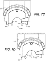
- FIGs. 7A-7D are top views of ram bodies that have improved hang off, according to some embodiments.
- FIGs. 7A-7D show variations of ram body tapers for improving hang off.
- FIG. 7A shows ram body 310 having upper centralizer lobe 320 with a taper section 750 that is 60 degrees measured from the ram actuation direction 682.
- FIG. 7B shows ram body 310 having a taper section 752 that is 90 degrees measured from the ram actuation direction 682. Note that in this case, the entire upper centralizer lobe may be omitted.
- FIG. 7C shows ram body 310 having upper centralizer lobe 320 with a taper section 754 that is 15 degrees measured from the ram actuation direction 682.
- the lower centralizer lobe 322 includes a taper section 756 that also is 15 degrees measured from the ram actuation direction 682.
- FIG. 7D shows ram body 310 having upper centralizer lobe 320 with a taper section 758 that is 30 degrees measured from the ram actuation direction 682, but the taper 758 starts further back (away from the opposing ram) than taper 350 shown in FIGs. 3 , 4A , 4B , 5 and 6 , where the taper section starts approximately where the semi-circular opening 324 is approximately parallel to the ram actuation direction.
- the taper can range from 5 degrees to 90 degrees and can be on the upper lobe and/or lower lobe. According to some embodiments, as measured parallel to the ram actuation direction, the taper can range from 10 degrees to 60 degrees and can be on the upper lobe and/or lower lobe. According to some embodiments, as measured parallel to the ram actuation direction, the taper can range from 20 degrees to 45 degrees and can be on at least the upper lobe. According to some embodiments, as measured parallel to the ram actuation direction, the taper can range from 10 degrees to 60 degrees and can be on the upper lobe and/or lower lobe.
- the taper start location can be anywhere along the central opening.
- the central opening doesn't have to be circular, but rather has a profile that is shaped to improve hang off load.
- the amount and location of the tapered section(s) and/or the profile and shape of the central opening of the ram body should be selected based on one or more of the following: shape and thickness of centralizer lobes, shape of central semi-circular ram body opening, anticipated tubing sizes, anticipated tool joint shoulder profiles, and anticipated hang off loads.
- FIGs. 8A and 8B are side are top views of ram bodies that have improved hang off, according to some embodiments.
- FIG. 8A is a side view of ram body 310 such as shown in FIGs. 3 , 4A , 4B , 5 , 6 and 7A .
- the dimensions of upper centralizing lobe 320 is shown for this example. In particular the length of lobe 320 is about 1.86 inches (47.4 mm) and the thickness of lobe 320 is about 0.63 inches (16 mm). In general, the longer and thinner the centralizing lobe, the greater the benefit for a taper (such as taper 350) or other shape to improve hang off capability.
- FIG. 8A is a side view of ram body 310 such as shown in FIGs. 3 , 4A , 4B , 5 , 6 and 7A .
- the dimensions of upper centralizing lobe 320 is shown for this example. In particular the length of lobe 320 is about 1.86 inches (47.4
- FIG. 8B is a side view of a different ram body 810 that has a centralizing lobe 820 that is shorter (1.41 inches - 35.8 mm) and thicker (0.72 inches - 18.2 mm) than lobe 320 of body 310.
- the shorter and thicker centralizing lobe 820 nevertheless benefits from a tapered section 850 for improved hang off capability.
- a tapered section is found to improve hang off for ram bodies having an upper centralizing lobe this a length of greater than about 1 inch and thinner than about 1 inch.
Applications Claiming Priority (1)
| Application Number | Priority Date | Filing Date | Title |
|---|---|---|---|
| US16/243,989 US11053764B2 (en) | 2019-01-09 | 2019-01-09 | Hang off ram preventer |
Publications (2)
| Publication Number | Publication Date |
|---|---|
| EP3680448A1 true EP3680448A1 (fr) | 2020-07-15 |
| EP3680448B1 EP3680448B1 (fr) | 2021-09-22 |
Family
ID=69156333
Family Applications (1)
| Application Number | Title | Priority Date | Filing Date |
|---|---|---|---|
| EP20150951.0A Active EP3680448B1 (fr) | 2019-01-09 | 2020-01-09 | Obturateur à mâchoires à décrochage amélioré |
Country Status (2)
| Country | Link |
|---|---|
| US (1) | US11053764B2 (fr) |
| EP (1) | EP3680448B1 (fr) |
Families Citing this family (2)
| Publication number | Priority date | Publication date | Assignee | Title |
|---|---|---|---|---|
| USD973734S1 (en) * | 2019-08-06 | 2022-12-27 | Nxl Technologies Inc. | Blind shear |
| US11530590B2 (en) * | 2019-11-27 | 2022-12-20 | Worldwide Oilfield Machine, Inc. | Interlocking dual v-shaped shear ram and method |
Citations (5)
| Publication number | Priority date | Publication date | Assignee | Title |
|---|---|---|---|---|
| US2912214A (en) * | 1954-03-01 | 1959-11-10 | Cameron Iron Works Inc | Blowout preventer |
| US5013005A (en) * | 1986-04-18 | 1991-05-07 | Cameron Iron Works, Inc. | Blowout preventer |
| US5575451A (en) * | 1995-05-02 | 1996-11-19 | Hydril Company | Blowout preventer ram for coil tubing |
| US6296225B1 (en) * | 2000-06-29 | 2001-10-02 | Cooper Cameron Corporation | Ram bore profile for variable bore packer ram in a ram type blowout preventer |
| US8727303B2 (en) | 2008-02-01 | 2014-05-20 | Cameron International Corporation | Variable bore packer for a blowout preventer |
Family Cites Families (12)
| Publication number | Priority date | Publication date | Assignee | Title |
|---|---|---|---|---|
| US3880436A (en) * | 1973-07-05 | 1975-04-29 | Rucker Co | Ram block |
| US4553730A (en) * | 1983-08-16 | 1985-11-19 | Vicic John C | Ram-type blowout preventer and packer therefor |
| US4518144A (en) * | 1983-09-01 | 1985-05-21 | Cameron Iron Works, Inc. | Ram-type blowout preventer and packer therefor |
| US4703938A (en) * | 1986-02-10 | 1987-11-03 | Fox Allan J | Seal for ram type blowout preventor |
| US4770387A (en) * | 1986-10-24 | 1988-09-13 | Nl Industries, Inc. | Variable ram seal for blowout preventers |
| US5009289A (en) * | 1987-03-23 | 1991-04-23 | Cooper Industries, Inc. | Blowout preventer string support |
| US5005802A (en) * | 1990-02-01 | 1991-04-09 | Cooper Industries, Inc. | Variable bore packer for a ram type blowout preventer |
| US5180137A (en) * | 1991-10-02 | 1993-01-19 | Hydril Company | Ram type blowout preventer having improved ram front packings |
| US6089526A (en) * | 1997-05-01 | 2000-07-18 | Stewart & Stevenson Services, Inc. | Ram type blowout preventor |
| US9828823B2 (en) * | 2014-04-01 | 2017-11-28 | Cameron International Corporation | Rod hang-off system |
| US10094193B2 (en) * | 2015-10-09 | 2018-10-09 | Cameron International Corporation | Blowout preventer with ram packer assemblies with support member |
| US10087698B2 (en) * | 2015-12-03 | 2018-10-02 | General Electric Company | Variable ram packer for blowout preventer |
-
2019
- 2019-01-09 US US16/243,989 patent/US11053764B2/en active Active
-
2020
- 2020-01-09 EP EP20150951.0A patent/EP3680448B1/fr active Active
Patent Citations (5)
| Publication number | Priority date | Publication date | Assignee | Title |
|---|---|---|---|---|
| US2912214A (en) * | 1954-03-01 | 1959-11-10 | Cameron Iron Works Inc | Blowout preventer |
| US5013005A (en) * | 1986-04-18 | 1991-05-07 | Cameron Iron Works, Inc. | Blowout preventer |
| US5575451A (en) * | 1995-05-02 | 1996-11-19 | Hydril Company | Blowout preventer ram for coil tubing |
| US6296225B1 (en) * | 2000-06-29 | 2001-10-02 | Cooper Cameron Corporation | Ram bore profile for variable bore packer ram in a ram type blowout preventer |
| US8727303B2 (en) | 2008-02-01 | 2014-05-20 | Cameron International Corporation | Variable bore packer for a blowout preventer |
Also Published As
| Publication number | Publication date |
|---|---|
| US20200217167A1 (en) | 2020-07-09 |
| EP3680448B1 (fr) | 2021-09-22 |
| US11053764B2 (en) | 2021-07-06 |
Similar Documents
| Publication | Publication Date | Title |
|---|---|---|
| US10233716B2 (en) | Blowout preventer including blind seal assembly | |
| US10316608B2 (en) | Compact cutting system and method | |
| US10167695B2 (en) | Blowout preventer including shear body | |
| WO2020219412A1 (fr) | Mâchoire à cisaillement de bloc d'obturation de puits | |
| EP3680448A1 (fr) | Obturateur à mâchoires à décrochage amélioré | |
| US20160186516A1 (en) | Smart Material Coupler | |
| US20160298409A1 (en) | High-Strength Blowout Preventer Shearing Ram and Connecting Rod | |
| US11286740B2 (en) | Blowout preventer shearing ram | |
| EP3959415B1 (fr) | Mâchoire à cisaillement de bloc d'obturation de puits | |
| US10081986B2 (en) | Subsea casing tieback | |
| US10309182B2 (en) | Annular blowout preventer apparatus | |
| US20150083943A1 (en) | Quadruple RAM BOP | |
| US10161213B2 (en) | Internal and external pressure seal assembly | |
| US10954738B2 (en) | Dual compact cutting device intervention system | |
| WO2021077083A1 (fr) | Ensemble d'étanchéité | |
| US20170175477A1 (en) | Annular blowout preventer | |
| US10655421B2 (en) | Compact cutting system and method | |
| US9702213B2 (en) | Marine riser system | |
| WO2022094569A1 (fr) | Vérin bidirectionnel pour bloc d'obturation de puits | |
| WO2024097042A1 (fr) | Pistons de verrouillage pour bloc obturateur de puits |
Legal Events
| Date | Code | Title | Description |
|---|---|---|---|
| PUAI | Public reference made under article 153(3) epc to a published international application that has entered the european phase |
Free format text: ORIGINAL CODE: 0009012 |
|
| STAA | Information on the status of an ep patent application or granted ep patent |
Free format text: STATUS: THE APPLICATION HAS BEEN PUBLISHED |
|
| AK | Designated contracting states |
Kind code of ref document: A1 Designated state(s): AL AT BE BG CH CY CZ DE DK EE ES FI FR GB GR HR HU IE IS IT LI LT LU LV MC MK MT NL NO PL PT RO RS SE SI SK SM TR |
|
| AX | Request for extension of the european patent |
Extension state: BA ME |
|
| STAA | Information on the status of an ep patent application or granted ep patent |
Free format text: STATUS: REQUEST FOR EXAMINATION WAS MADE |
|
| 17P | Request for examination filed |
Effective date: 20210121 |
|
| RBV | Designated contracting states (corrected) |
Designated state(s): AL AT BE BG CH CY CZ DE DK EE ES FI FR GB GR HR HU IE IS IT LI LT LU LV MC MK MT NL NO PL PT RO RS SE SI SK SM TR |
|
| RIC1 | Information provided on ipc code assigned before grant |
Ipc: E21B 33/12 20060101ALI20210305BHEP Ipc: E21B 33/06 20060101AFI20210305BHEP |
|
| GRAP | Despatch of communication of intention to grant a patent |
Free format text: ORIGINAL CODE: EPIDOSNIGR1 |
|
| STAA | Information on the status of an ep patent application or granted ep patent |
Free format text: STATUS: GRANT OF PATENT IS INTENDED |
|
| INTG | Intention to grant announced |
Effective date: 20210416 |
|
| GRAS | Grant fee paid |
Free format text: ORIGINAL CODE: EPIDOSNIGR3 |
|
| GRAA | (expected) grant |
Free format text: ORIGINAL CODE: 0009210 |
|
| STAA | Information on the status of an ep patent application or granted ep patent |
Free format text: STATUS: THE PATENT HAS BEEN GRANTED |
|
| AK | Designated contracting states |
Kind code of ref document: B1 Designated state(s): AL AT BE BG CH CY CZ DE DK EE ES FI FR GB GR HR HU IE IS IT LI LT LU LV MC MK MT NL NO PL PT RO RS SE SI SK SM TR |
|
| REG | Reference to a national code |
Ref country code: GB Ref legal event code: FG4D |
|
| REG | Reference to a national code |
Ref country code: DE Ref legal event code: R096 Ref document number: 602020000559 Country of ref document: DE |
|
| REG | Reference to a national code |
Ref country code: IE Ref legal event code: FG4D |
|
| REG | Reference to a national code |
Ref country code: CH Ref legal event code: EP Ref country code: AT Ref legal event code: REF Ref document number: 1432460 Country of ref document: AT Kind code of ref document: T Effective date: 20211015 |
|
| REG | Reference to a national code |
Ref country code: LT Ref legal event code: MG9D |
|
| REG | Reference to a national code |
Ref country code: NL Ref legal event code: FP |
|
| PG25 | Lapsed in a contracting state [announced via postgrant information from national office to epo] |
Ref country code: LT Free format text: LAPSE BECAUSE OF FAILURE TO SUBMIT A TRANSLATION OF THE DESCRIPTION OR TO PAY THE FEE WITHIN THE PRESCRIBED TIME-LIMIT Effective date: 20210922 Ref country code: BG Free format text: LAPSE BECAUSE OF FAILURE TO SUBMIT A TRANSLATION OF THE DESCRIPTION OR TO PAY THE FEE WITHIN THE PRESCRIBED TIME-LIMIT Effective date: 20211222 Ref country code: FI Free format text: LAPSE BECAUSE OF FAILURE TO SUBMIT A TRANSLATION OF THE DESCRIPTION OR TO PAY THE FEE WITHIN THE PRESCRIBED TIME-LIMIT Effective date: 20210922 Ref country code: HR Free format text: LAPSE BECAUSE OF FAILURE TO SUBMIT A TRANSLATION OF THE DESCRIPTION OR TO PAY THE FEE WITHIN THE PRESCRIBED TIME-LIMIT Effective date: 20210922 Ref country code: RS Free format text: LAPSE BECAUSE OF FAILURE TO SUBMIT A TRANSLATION OF THE DESCRIPTION OR TO PAY THE FEE WITHIN THE PRESCRIBED TIME-LIMIT Effective date: 20210922 Ref country code: SE Free format text: LAPSE BECAUSE OF FAILURE TO SUBMIT A TRANSLATION OF THE DESCRIPTION OR TO PAY THE FEE WITHIN THE PRESCRIBED TIME-LIMIT Effective date: 20210922 |
|
| REG | Reference to a national code |
Ref country code: AT Ref legal event code: MK05 Ref document number: 1432460 Country of ref document: AT Kind code of ref document: T Effective date: 20210922 |
|
| PG25 | Lapsed in a contracting state [announced via postgrant information from national office to epo] |
Ref country code: LV Free format text: LAPSE BECAUSE OF FAILURE TO SUBMIT A TRANSLATION OF THE DESCRIPTION OR TO PAY THE FEE WITHIN THE PRESCRIBED TIME-LIMIT Effective date: 20210922 Ref country code: GR Free format text: LAPSE BECAUSE OF FAILURE TO SUBMIT A TRANSLATION OF THE DESCRIPTION OR TO PAY THE FEE WITHIN THE PRESCRIBED TIME-LIMIT Effective date: 20211223 |
|
| REG | Reference to a national code |
Ref country code: NO Ref legal event code: T2 Effective date: 20210922 |
|
| PG25 | Lapsed in a contracting state [announced via postgrant information from national office to epo] |
Ref country code: AT Free format text: LAPSE BECAUSE OF FAILURE TO SUBMIT A TRANSLATION OF THE DESCRIPTION OR TO PAY THE FEE WITHIN THE PRESCRIBED TIME-LIMIT Effective date: 20210922 |
|
| PG25 | Lapsed in a contracting state [announced via postgrant information from national office to epo] |
Ref country code: IS Free format text: LAPSE BECAUSE OF FAILURE TO SUBMIT A TRANSLATION OF THE DESCRIPTION OR TO PAY THE FEE WITHIN THE PRESCRIBED TIME-LIMIT Effective date: 20220122 Ref country code: SK Free format text: LAPSE BECAUSE OF FAILURE TO SUBMIT A TRANSLATION OF THE DESCRIPTION OR TO PAY THE FEE WITHIN THE PRESCRIBED TIME-LIMIT Effective date: 20210922 Ref country code: RO Free format text: LAPSE BECAUSE OF FAILURE TO SUBMIT A TRANSLATION OF THE DESCRIPTION OR TO PAY THE FEE WITHIN THE PRESCRIBED TIME-LIMIT Effective date: 20210922 Ref country code: PT Free format text: LAPSE BECAUSE OF FAILURE TO SUBMIT A TRANSLATION OF THE DESCRIPTION OR TO PAY THE FEE WITHIN THE PRESCRIBED TIME-LIMIT Effective date: 20220124 Ref country code: PL Free format text: LAPSE BECAUSE OF FAILURE TO SUBMIT A TRANSLATION OF THE DESCRIPTION OR TO PAY THE FEE WITHIN THE PRESCRIBED TIME-LIMIT Effective date: 20210922 Ref country code: ES Free format text: LAPSE BECAUSE OF FAILURE TO SUBMIT A TRANSLATION OF THE DESCRIPTION OR TO PAY THE FEE WITHIN THE PRESCRIBED TIME-LIMIT Effective date: 20210922 Ref country code: EE Free format text: LAPSE BECAUSE OF FAILURE TO SUBMIT A TRANSLATION OF THE DESCRIPTION OR TO PAY THE FEE WITHIN THE PRESCRIBED TIME-LIMIT Effective date: 20210922 Ref country code: CZ Free format text: LAPSE BECAUSE OF FAILURE TO SUBMIT A TRANSLATION OF THE DESCRIPTION OR TO PAY THE FEE WITHIN THE PRESCRIBED TIME-LIMIT Effective date: 20210922 Ref country code: AL Free format text: LAPSE BECAUSE OF FAILURE TO SUBMIT A TRANSLATION OF THE DESCRIPTION OR TO PAY THE FEE WITHIN THE PRESCRIBED TIME-LIMIT Effective date: 20210922 |
|
| REG | Reference to a national code |
Ref country code: DE Ref legal event code: R097 Ref document number: 602020000559 Country of ref document: DE |
|
| PG25 | Lapsed in a contracting state [announced via postgrant information from national office to epo] |
Ref country code: DK Free format text: LAPSE BECAUSE OF FAILURE TO SUBMIT A TRANSLATION OF THE DESCRIPTION OR TO PAY THE FEE WITHIN THE PRESCRIBED TIME-LIMIT Effective date: 20210922 |
|
| PLBE | No opposition filed within time limit |
Free format text: ORIGINAL CODE: 0009261 |
|
| STAA | Information on the status of an ep patent application or granted ep patent |
Free format text: STATUS: NO OPPOSITION FILED WITHIN TIME LIMIT |
|
| 26N | No opposition filed |
Effective date: 20220623 |
|
| PG25 | Lapsed in a contracting state [announced via postgrant information from national office to epo] |
Ref country code: MC Free format text: LAPSE BECAUSE OF FAILURE TO SUBMIT A TRANSLATION OF THE DESCRIPTION OR TO PAY THE FEE WITHIN THE PRESCRIBED TIME-LIMIT Effective date: 20210922 |
|
| REG | Reference to a national code |
Ref country code: BE Ref legal event code: MM Effective date: 20220131 |
|
| PG25 | Lapsed in a contracting state [announced via postgrant information from national office to epo] |
Ref country code: LU Free format text: LAPSE BECAUSE OF NON-PAYMENT OF DUE FEES Effective date: 20220109 |
|
| PG25 | Lapsed in a contracting state [announced via postgrant information from national office to epo] |
Ref country code: SI Free format text: LAPSE BECAUSE OF FAILURE TO SUBMIT A TRANSLATION OF THE DESCRIPTION OR TO PAY THE FEE WITHIN THE PRESCRIBED TIME-LIMIT Effective date: 20210922 Ref country code: BE Free format text: LAPSE BECAUSE OF NON-PAYMENT OF DUE FEES Effective date: 20220131 |
|
| PG25 | Lapsed in a contracting state [announced via postgrant information from national office to epo] |
Ref country code: IT Free format text: LAPSE BECAUSE OF FAILURE TO SUBMIT A TRANSLATION OF THE DESCRIPTION OR TO PAY THE FEE WITHIN THE PRESCRIBED TIME-LIMIT Effective date: 20210922 Ref country code: IE Free format text: LAPSE BECAUSE OF NON-PAYMENT OF DUE FEES Effective date: 20220109 |
|
| PGFP | Annual fee paid to national office [announced via postgrant information from national office to epo] |
Ref country code: NO Payment date: 20230110 Year of fee payment: 4 |
|
| REG | Reference to a national code |
Ref country code: CH Ref legal event code: PL |
|
| PG25 | Lapsed in a contracting state [announced via postgrant information from national office to epo] |
Ref country code: LI Free format text: LAPSE BECAUSE OF NON-PAYMENT OF DUE FEES Effective date: 20230131 Ref country code: CH Free format text: LAPSE BECAUSE OF NON-PAYMENT OF DUE FEES Effective date: 20230131 |
|
| PGFP | Annual fee paid to national office [announced via postgrant information from national office to epo] |
Ref country code: NL Payment date: 20231123 Year of fee payment: 5 |
|
| P01 | Opt-out of the competence of the unified patent court (upc) registered |
Effective date: 20231208 |
|
| PGFP | Annual fee paid to national office [announced via postgrant information from national office to epo] |
Ref country code: GB Payment date: 20231116 Year of fee payment: 5 |
|
| PGFP | Annual fee paid to national office [announced via postgrant information from national office to epo] |
Ref country code: FR Payment date: 20231122 Year of fee payment: 5 |
|
| PG25 | Lapsed in a contracting state [announced via postgrant information from national office to epo] |
Ref country code: SM Free format text: LAPSE BECAUSE OF FAILURE TO SUBMIT A TRANSLATION OF THE DESCRIPTION OR TO PAY THE FEE WITHIN THE PRESCRIBED TIME-LIMIT Effective date: 20210922 Ref country code: MK Free format text: LAPSE BECAUSE OF FAILURE TO SUBMIT A TRANSLATION OF THE DESCRIPTION OR TO PAY THE FEE WITHIN THE PRESCRIBED TIME-LIMIT Effective date: 20210922 Ref country code: CY Free format text: LAPSE BECAUSE OF FAILURE TO SUBMIT A TRANSLATION OF THE DESCRIPTION OR TO PAY THE FEE WITHIN THE PRESCRIBED TIME-LIMIT Effective date: 20210922 |
|
| PGFP | Annual fee paid to national office [announced via postgrant information from national office to epo] |
Ref country code: DE Payment date: 20231121 Year of fee payment: 5 |