EP3680367A2 - Film forming device and method for forming metal film using the same - Google Patents
Film forming device and method for forming metal film using the same Download PDFInfo
- Publication number
- EP3680367A2 EP3680367A2 EP19205455.9A EP19205455A EP3680367A2 EP 3680367 A2 EP3680367 A2 EP 3680367A2 EP 19205455 A EP19205455 A EP 19205455A EP 3680367 A2 EP3680367 A2 EP 3680367A2
- Authority
- EP
- European Patent Office
- Prior art keywords
- porous membrane
- cathode
- anode
- film
- metal
- Prior art date
- Legal status (The legal status is an assumption and is not a legal conclusion. Google has not performed a legal analysis and makes no representation as to the accuracy of the status listed.)
- Withdrawn
Links
- 239000002184 metal Substances 0.000 title claims abstract description 51
- 229910052751 metal Inorganic materials 0.000 title claims abstract description 51
- 238000000034 method Methods 0.000 title claims abstract description 50
- 239000012528 membrane Substances 0.000 claims abstract description 128
- 125000000524 functional group Chemical group 0.000 claims abstract description 27
- 238000005342 ion exchange Methods 0.000 claims abstract description 23
- 229920000098 polyolefin Polymers 0.000 claims abstract description 16
- PXHVJJICTQNCMI-UHFFFAOYSA-N Nickel Chemical compound [Ni] PXHVJJICTQNCMI-UHFFFAOYSA-N 0.000 claims description 64
- 239000011148 porous material Substances 0.000 claims description 49
- LFQSCWFLJHTTHZ-UHFFFAOYSA-N Ethanol Chemical compound CCO LFQSCWFLJHTTHZ-UHFFFAOYSA-N 0.000 claims description 32
- 229910052759 nickel Inorganic materials 0.000 claims description 32
- 239000011244 liquid electrolyte Substances 0.000 claims description 30
- ATJFFYVFTNAWJD-UHFFFAOYSA-N Tin Chemical compound [Sn] ATJFFYVFTNAWJD-UHFFFAOYSA-N 0.000 claims description 25
- 229910052718 tin Inorganic materials 0.000 claims description 21
- AFVFQIVMOAPDHO-UHFFFAOYSA-N Methanesulfonic acid Chemical compound CS(O)(=O)=O AFVFQIVMOAPDHO-UHFFFAOYSA-N 0.000 claims description 12
- 230000035699 permeability Effects 0.000 claims description 9
- 230000033116 oxidation-reduction process Effects 0.000 claims description 7
- 229940098779 methanesulfonic acid Drugs 0.000 claims description 6
- 150000002500 ions Chemical class 0.000 claims description 4
- 239000000243 solution Substances 0.000 description 35
- 239000000758 substrate Substances 0.000 description 26
- 239000007784 solid electrolyte Substances 0.000 description 22
- 229910021645 metal ion Inorganic materials 0.000 description 19
- 230000000052 comparative effect Effects 0.000 description 15
- 238000000151 deposition Methods 0.000 description 13
- RYGMFSIKBFXOCR-UHFFFAOYSA-N Copper Chemical compound [Cu] RYGMFSIKBFXOCR-UHFFFAOYSA-N 0.000 description 9
- KFZMGEQAYNKOFK-UHFFFAOYSA-N Isopropanol Chemical compound CC(C)O KFZMGEQAYNKOFK-UHFFFAOYSA-N 0.000 description 9
- 230000015572 biosynthetic process Effects 0.000 description 9
- 229910052802 copper Inorganic materials 0.000 description 9
- 239000010949 copper Substances 0.000 description 9
- 238000010438 heat treatment Methods 0.000 description 9
- 230000008021 deposition Effects 0.000 description 7
- QTBSBXVTEAMEQO-UHFFFAOYSA-N Acetic acid Chemical compound CC(O)=O QTBSBXVTEAMEQO-UHFFFAOYSA-N 0.000 description 6
- 239000011259 mixed solution Substances 0.000 description 6
- 239000003014 ion exchange membrane Substances 0.000 description 5
- XLYOFNOQVPJJNP-UHFFFAOYSA-N water Substances O XLYOFNOQVPJJNP-UHFFFAOYSA-N 0.000 description 5
- 102000004310 Ion Channels Human genes 0.000 description 4
- QSHDDOUJBYECFT-UHFFFAOYSA-N mercury Chemical compound [Hg] QSHDDOUJBYECFT-UHFFFAOYSA-N 0.000 description 4
- 229910052753 mercury Inorganic materials 0.000 description 4
- 238000007747 plating Methods 0.000 description 4
- 229920000642 polymer Polymers 0.000 description 4
- 239000002904 solvent Substances 0.000 description 4
- 238000012360 testing method Methods 0.000 description 4
- 229920000557 Nafion® Polymers 0.000 description 3
- 239000004642 Polyimide Substances 0.000 description 3
- 239000007864 aqueous solution Substances 0.000 description 3
- 125000004432 carbon atom Chemical group C* 0.000 description 3
- 125000002843 carboxylic acid group Chemical group 0.000 description 3
- 125000004430 oxygen atom Chemical group O* 0.000 description 3
- 230000035515 penetration Effects 0.000 description 3
- -1 polyethylene Polymers 0.000 description 3
- 229920001721 polyimide Polymers 0.000 description 3
- 229910001432 tin ion Inorganic materials 0.000 description 3
- YXIWHUQXZSMYRE-UHFFFAOYSA-N 1,3-benzothiazole-2-thiol Chemical compound C1=CC=C2SC(S)=NC2=C1 YXIWHUQXZSMYRE-UHFFFAOYSA-N 0.000 description 2
- POKOASTYJWUQJG-UHFFFAOYSA-M 1-butylpyridin-1-ium;chloride Chemical compound [Cl-].CCCC[N+]1=CC=CC=C1 POKOASTYJWUQJG-UHFFFAOYSA-M 0.000 description 2
- GWQYPLXGJIXMMV-UHFFFAOYSA-M 1-ethyl-3-methylimidazol-3-ium;bromide Chemical compound [Br-].CCN1C=C[N+](C)=C1 GWQYPLXGJIXMMV-UHFFFAOYSA-M 0.000 description 2
- BMQZYMYBQZGEEY-UHFFFAOYSA-M 1-ethyl-3-methylimidazolium chloride Chemical compound [Cl-].CCN1C=C[N+](C)=C1 BMQZYMYBQZGEEY-UHFFFAOYSA-M 0.000 description 2
- UFHFLCQGNIYNRP-UHFFFAOYSA-N Hydrogen Chemical compound [H][H] UFHFLCQGNIYNRP-UHFFFAOYSA-N 0.000 description 2
- QAOWNCQODCNURD-UHFFFAOYSA-N Sulfuric acid Chemical compound OS(O)(=O)=O QAOWNCQODCNURD-UHFFFAOYSA-N 0.000 description 2
- 238000004458 analytical method Methods 0.000 description 2
- 238000005349 anion exchange Methods 0.000 description 2
- 125000004429 atom Chemical group 0.000 description 2
- 229910001423 beryllium ion Inorganic materials 0.000 description 2
- LRESCJAINPKJTO-UHFFFAOYSA-N bis(trifluoromethylsulfonyl)azanide;1-ethyl-3-methylimidazol-3-ium Chemical compound CCN1C=C[N+](C)=C1.FC(F)(F)S(=O)(=O)[N-]S(=O)(=O)C(F)(F)F LRESCJAINPKJTO-UHFFFAOYSA-N 0.000 description 2
- SLEKRZBYCSJUNO-UHFFFAOYSA-N bis(trifluoromethylsulfonyl)azanide;hexyl(trimethyl)azanium Chemical compound CCCCCC[N+](C)(C)C.FC(F)(F)S(=O)(=O)[N-]S(=O)(=O)C(F)(F)F SLEKRZBYCSJUNO-UHFFFAOYSA-N 0.000 description 2
- 238000005341 cation exchange Methods 0.000 description 2
- 239000011248 coating agent Substances 0.000 description 2
- 238000000576 coating method Methods 0.000 description 2
- 230000007797 corrosion Effects 0.000 description 2
- 238000005260 corrosion Methods 0.000 description 2
- 238000009826 distribution Methods 0.000 description 2
- 239000003792 electrolyte Substances 0.000 description 2
- PCHJSUWPFVWCPO-UHFFFAOYSA-N gold Chemical compound [Au] PCHJSUWPFVWCPO-UHFFFAOYSA-N 0.000 description 2
- 229910052737 gold Inorganic materials 0.000 description 2
- 239000010931 gold Substances 0.000 description 2
- 239000001257 hydrogen Substances 0.000 description 2
- 229910052739 hydrogen Inorganic materials 0.000 description 2
- 239000002608 ionic liquid Substances 0.000 description 2
- 238000004519 manufacturing process Methods 0.000 description 2
- 238000005259 measurement Methods 0.000 description 2
- AICMYQIGFPHNCY-UHFFFAOYSA-J methanesulfonate;tin(4+) Chemical compound [Sn+4].CS([O-])(=O)=O.CS([O-])(=O)=O.CS([O-])(=O)=O.CS([O-])(=O)=O AICMYQIGFPHNCY-UHFFFAOYSA-J 0.000 description 2
- 239000000203 mixture Substances 0.000 description 2
- 239000002736 nonionic surfactant Substances 0.000 description 2
- 239000003960 organic solvent Substances 0.000 description 2
- 238000004451 qualitative analysis Methods 0.000 description 2
- 238000004445 quantitative analysis Methods 0.000 description 2
- 230000009257 reactivity Effects 0.000 description 2
- 238000000926 separation method Methods 0.000 description 2
- 125000000542 sulfonic acid group Chemical group 0.000 description 2
- MQAYPFVXSPHGJM-UHFFFAOYSA-M trimethyl(phenyl)azanium;chloride Chemical compound [Cl-].C[N+](C)(C)C1=CC=CC=C1 MQAYPFVXSPHGJM-UHFFFAOYSA-M 0.000 description 2
- YJLUBHOZZTYQIP-UHFFFAOYSA-N 2-[5-[2-(2,3-dihydro-1H-inden-2-ylamino)pyrimidin-5-yl]-1,3,4-oxadiazol-2-yl]-1-(2,4,6,7-tetrahydrotriazolo[4,5-c]pyridin-5-yl)ethanone Chemical compound C1C(CC2=CC=CC=C12)NC1=NC=C(C=N1)C1=NN=C(O1)CC(=O)N1CC2=C(CC1)NN=N2 YJLUBHOZZTYQIP-UHFFFAOYSA-N 0.000 description 1
- WTFUTSCZYYCBAY-SXBRIOAWSA-N 6-[(E)-C-[[4-[2-(2,3-dihydro-1H-inden-2-ylamino)pyrimidin-5-yl]piperazin-1-yl]methyl]-N-hydroxycarbonimidoyl]-3H-1,3-benzoxazol-2-one Chemical compound C1C(CC2=CC=CC=C12)NC1=NC=C(C=N1)N1CCN(CC1)C/C(=N/O)/C1=CC2=C(NC(O2)=O)C=C1 WTFUTSCZYYCBAY-SXBRIOAWSA-N 0.000 description 1
- 229910000789 Aluminium-silicon alloy Inorganic materials 0.000 description 1
- IAYPIBMASNFSPL-UHFFFAOYSA-N Ethylene oxide Chemical compound C1CO1 IAYPIBMASNFSPL-UHFFFAOYSA-N 0.000 description 1
- 238000004566 IR spectroscopy Methods 0.000 description 1
- HBBGRARXTFLTSG-UHFFFAOYSA-N Lithium ion Chemical compound [Li+] HBBGRARXTFLTSG-UHFFFAOYSA-N 0.000 description 1
- MKYBYDHXWVHEJW-UHFFFAOYSA-N N-[1-oxo-1-(2,4,6,7-tetrahydrotriazolo[4,5-c]pyridin-5-yl)propan-2-yl]-2-[[3-(trifluoromethoxy)phenyl]methylamino]pyrimidine-5-carboxamide Chemical compound O=C(C(C)NC(=O)C=1C=NC(=NC=1)NCC1=CC(=CC=C1)OC(F)(F)F)N1CC2=C(CC1)NN=N2 MKYBYDHXWVHEJW-UHFFFAOYSA-N 0.000 description 1
- 238000005481 NMR spectroscopy Methods 0.000 description 1
- VEQPNABPJHWNSG-UHFFFAOYSA-N Nickel(2+) Chemical compound [Ni+2] VEQPNABPJHWNSG-UHFFFAOYSA-N 0.000 description 1
- 229910021586 Nickel(II) chloride Inorganic materials 0.000 description 1
- 239000004698 Polyethylene Substances 0.000 description 1
- 239000004743 Polypropylene Substances 0.000 description 1
- GOOHAUXETOMSMM-UHFFFAOYSA-N Propylene oxide Chemical compound CC1CO1 GOOHAUXETOMSMM-UHFFFAOYSA-N 0.000 description 1
- JUJWROOIHBZHMG-UHFFFAOYSA-N Pyridine Chemical group C1=CC=NC=C1 JUJWROOIHBZHMG-UHFFFAOYSA-N 0.000 description 1
- 238000001069 Raman spectroscopy Methods 0.000 description 1
- BQCADISMDOOEFD-UHFFFAOYSA-N Silver Chemical compound [Ag] BQCADISMDOOEFD-UHFFFAOYSA-N 0.000 description 1
- 238000002441 X-ray diffraction Methods 0.000 description 1
- 238000004833 X-ray photoelectron spectroscopy Methods 0.000 description 1
- 239000002253 acid Substances 0.000 description 1
- 230000004913 activation Effects 0.000 description 1
- 239000002390 adhesive tape Substances 0.000 description 1
- 239000003513 alkali Substances 0.000 description 1
- 150000001336 alkenes Chemical group 0.000 description 1
- 125000000217 alkyl group Chemical group 0.000 description 1
- 239000003963 antioxidant agent Substances 0.000 description 1
- 230000003078 antioxidant effect Effects 0.000 description 1
- 125000003118 aryl group Chemical group 0.000 description 1
- 238000009835 boiling Methods 0.000 description 1
- JHRWWRDRBPCWTF-OLQVQODUSA-N captafol Chemical group C1C=CC[C@H]2C(=O)N(SC(Cl)(Cl)C(Cl)Cl)C(=O)[C@H]21 JHRWWRDRBPCWTF-OLQVQODUSA-N 0.000 description 1
- 238000005266 casting Methods 0.000 description 1
- 239000003795 chemical substances by application Substances 0.000 description 1
- 229920003020 cross-linked polyethylene Polymers 0.000 description 1
- 239000004703 cross-linked polyethylene Substances 0.000 description 1
- 238000013461 design Methods 0.000 description 1
- 238000009713 electroplating Methods 0.000 description 1
- 125000002534 ethynyl group Chemical group [H]C#C* 0.000 description 1
- 238000000605 extraction Methods 0.000 description 1
- 230000008014 freezing Effects 0.000 description 1
- 238000007710 freezing Methods 0.000 description 1
- 230000004927 fusion Effects 0.000 description 1
- 239000007789 gas Substances 0.000 description 1
- 238000009499 grossing Methods 0.000 description 1
- 239000001307 helium Substances 0.000 description 1
- 229910052734 helium Inorganic materials 0.000 description 1
- SWQJXJOGLNCZEY-UHFFFAOYSA-N helium atom Chemical compound [He] SWQJXJOGLNCZEY-UHFFFAOYSA-N 0.000 description 1
- 230000002209 hydrophobic effect Effects 0.000 description 1
- 125000002883 imidazolyl group Chemical group 0.000 description 1
- 238000005470 impregnation Methods 0.000 description 1
- 239000007788 liquid Substances 0.000 description 1
- 229910001416 lithium ion Inorganic materials 0.000 description 1
- 238000002844 melting Methods 0.000 description 1
- 230000008018 melting Effects 0.000 description 1
- 238000002156 mixing Methods 0.000 description 1
- 229940078487 nickel acetate tetrahydrate Drugs 0.000 description 1
- LAIZPRYFQUWUBN-UHFFFAOYSA-L nickel chloride hexahydrate Chemical compound O.O.O.O.O.O.[Cl-].[Cl-].[Ni+2] LAIZPRYFQUWUBN-UHFFFAOYSA-L 0.000 description 1
- QMMRZOWCJAIUJA-UHFFFAOYSA-L nickel dichloride Chemical compound Cl[Ni]Cl QMMRZOWCJAIUJA-UHFFFAOYSA-L 0.000 description 1
- 229910001453 nickel ion Inorganic materials 0.000 description 1
- OINIXPNQKAZCRL-UHFFFAOYSA-L nickel(2+);diacetate;tetrahydrate Chemical compound O.O.O.O.[Ni+2].CC([O-])=O.CC([O-])=O OINIXPNQKAZCRL-UHFFFAOYSA-L 0.000 description 1
- 150000002894 organic compounds Chemical class 0.000 description 1
- 238000005191 phase separation Methods 0.000 description 1
- ABLZXFCXXLZCGV-UHFFFAOYSA-N phosphonic acid group Chemical group P(O)(O)=O ABLZXFCXXLZCGV-UHFFFAOYSA-N 0.000 description 1
- 229920003223 poly(pyromellitimide-1,4-diphenyl ether) Polymers 0.000 description 1
- 229920000573 polyethylene Polymers 0.000 description 1
- 229920001155 polypropylene Polymers 0.000 description 1
- 229920005606 polypropylene copolymer Polymers 0.000 description 1
- 238000003825 pressing Methods 0.000 description 1
- 238000012545 processing Methods 0.000 description 1
- 125000004076 pyridyl group Chemical group 0.000 description 1
- 125000001453 quaternary ammonium group Chemical group 0.000 description 1
- 239000011347 resin Substances 0.000 description 1
- 229920005989 resin Polymers 0.000 description 1
- 229920006395 saturated elastomer Polymers 0.000 description 1
- 229910052709 silver Inorganic materials 0.000 description 1
- 239000004332 silver Substances 0.000 description 1
- 239000000126 substance Substances 0.000 description 1
- 125000001302 tertiary amino group Chemical group 0.000 description 1
- 239000011135 tin Substances 0.000 description 1
- 238000000870 ultraviolet spectroscopy Methods 0.000 description 1
- 239000002699 waste material Substances 0.000 description 1
Images


Classifications
-
- C—CHEMISTRY; METALLURGY
- C25—ELECTROLYTIC OR ELECTROPHORETIC PROCESSES; APPARATUS THEREFOR
- C25D—PROCESSES FOR THE ELECTROLYTIC OR ELECTROPHORETIC PRODUCTION OF COATINGS; ELECTROFORMING; APPARATUS THEREFOR
- C25D5/00—Electroplating characterised by the process; Pretreatment or after-treatment of workpieces
- C25D5/04—Electroplating with moving electrodes
- C25D5/06—Brush or pad plating
-
- C—CHEMISTRY; METALLURGY
- C25—ELECTROLYTIC OR ELECTROPHORETIC PROCESSES; APPARATUS THEREFOR
- C25D—PROCESSES FOR THE ELECTROLYTIC OR ELECTROPHORETIC PRODUCTION OF COATINGS; ELECTROFORMING; APPARATUS THEREFOR
- C25D3/00—Electroplating: Baths therefor
- C25D3/02—Electroplating: Baths therefor from solutions
- C25D3/12—Electroplating: Baths therefor from solutions of nickel or cobalt
-
- C—CHEMISTRY; METALLURGY
- C25—ELECTROLYTIC OR ELECTROPHORETIC PROCESSES; APPARATUS THEREFOR
- C25D—PROCESSES FOR THE ELECTROLYTIC OR ELECTROPHORETIC PRODUCTION OF COATINGS; ELECTROFORMING; APPARATUS THEREFOR
- C25D17/00—Constructional parts, or assemblies thereof, of cells for electrolytic coating
- C25D17/002—Cell separation, e.g. membranes, diaphragms
-
- C—CHEMISTRY; METALLURGY
- C25—ELECTROLYTIC OR ELECTROPHORETIC PROCESSES; APPARATUS THEREFOR
- C25D—PROCESSES FOR THE ELECTROLYTIC OR ELECTROPHORETIC PRODUCTION OF COATINGS; ELECTROFORMING; APPARATUS THEREFOR
- C25D17/00—Constructional parts, or assemblies thereof, of cells for electrolytic coating
-
- C—CHEMISTRY; METALLURGY
- C25—ELECTROLYTIC OR ELECTROPHORETIC PROCESSES; APPARATUS THEREFOR
- C25D—PROCESSES FOR THE ELECTROLYTIC OR ELECTROPHORETIC PRODUCTION OF COATINGS; ELECTROFORMING; APPARATUS THEREFOR
- C25D17/00—Constructional parts, or assemblies thereof, of cells for electrolytic coating
- C25D17/10—Electrodes, e.g. composition, counter electrode
-
- C—CHEMISTRY; METALLURGY
- C25—ELECTROLYTIC OR ELECTROPHORETIC PROCESSES; APPARATUS THEREFOR
- C25D—PROCESSES FOR THE ELECTROLYTIC OR ELECTROPHORETIC PRODUCTION OF COATINGS; ELECTROFORMING; APPARATUS THEREFOR
- C25D17/00—Constructional parts, or assemblies thereof, of cells for electrolytic coating
- C25D17/10—Electrodes, e.g. composition, counter electrode
- C25D17/14—Electrodes, e.g. composition, counter electrode for pad-plating
-
- C—CHEMISTRY; METALLURGY
- C25—ELECTROLYTIC OR ELECTROPHORETIC PROCESSES; APPARATUS THEREFOR
- C25D—PROCESSES FOR THE ELECTROLYTIC OR ELECTROPHORETIC PRODUCTION OF COATINGS; ELECTROFORMING; APPARATUS THEREFOR
- C25D21/00—Processes for servicing or operating cells for electrolytic coating
- C25D21/02—Heating or cooling
-
- C—CHEMISTRY; METALLURGY
- C25—ELECTROLYTIC OR ELECTROPHORETIC PROCESSES; APPARATUS THEREFOR
- C25D—PROCESSES FOR THE ELECTROLYTIC OR ELECTROPHORETIC PRODUCTION OF COATINGS; ELECTROFORMING; APPARATUS THEREFOR
- C25D3/00—Electroplating: Baths therefor
- C25D3/02—Electroplating: Baths therefor from solutions
- C25D3/30—Electroplating: Baths therefor from solutions of tin
-
- C—CHEMISTRY; METALLURGY
- C25—ELECTROLYTIC OR ELECTROPHORETIC PROCESSES; APPARATUS THEREFOR
- C25D—PROCESSES FOR THE ELECTROLYTIC OR ELECTROPHORETIC PRODUCTION OF COATINGS; ELECTROFORMING; APPARATUS THEREFOR
- C25D3/00—Electroplating: Baths therefor
- C25D3/02—Electroplating: Baths therefor from solutions
- C25D3/30—Electroplating: Baths therefor from solutions of tin
- C25D3/32—Electroplating: Baths therefor from solutions of tin characterised by the organic bath constituents used
-
- C—CHEMISTRY; METALLURGY
- C25—ELECTROLYTIC OR ELECTROPHORETIC PROCESSES; APPARATUS THEREFOR
- C25D—PROCESSES FOR THE ELECTROLYTIC OR ELECTROPHORETIC PRODUCTION OF COATINGS; ELECTROFORMING; APPARATUS THEREFOR
- C25D5/00—Electroplating characterised by the process; Pretreatment or after-treatment of workpieces
- C25D5/10—Electroplating with more than one layer of the same or of different metals
- C25D5/12—Electroplating with more than one layer of the same or of different metals at least one layer being of nickel or chromium
Definitions
- the present disclosure relates to a film forming device for forming a metal film and a method for forming the metal film using the same.
- JP 2016-169399 A describes a method referred to as a solid electrolyte deposition (SED) method as a method for forming a metal coating.
- a solid electrolyte membrane is disposed between an anode and a cathode (substrate), an aqueous solution containing metal ions is provided between the anode and the solid electrolyte membrane, the solid electrolyte membrane is brought into contact with the substrate, and a voltage is applied between the anode and the cathode, such that the metal ions turn into metal deposit on the substrate to form a metal coating on a surface of the substrate.
- JP 2015-218366 A teaches that a separator (separation membrane) modified by introducing a carboxylic acid group or its derivative is used as a separator for separating a cathode from an anode chamber in an electroplating cell.
- the solid electrolyte membrane described in JP 2016-169399 A and the separation membrane described in JP 2015-218366 A have ion-exchange functional groups. According to examinations by the inventor, the solid electrolyte deposition methods using such membranes have a problem of low current efficiency.
- the present disclosure provides a film forming device capable of forming a metal film at a high current efficiency, in other words, at a high film forming rate and a method for forming the metal film using the film forming device.
- a film forming device for forming a metal film that includes an anode, a cathode, a porous membrane, a solution container, and a power supply.
- the porous membrane is disposed between the anode and the cathode to be capable of contacting the cathode.
- the solution container defines a solution containing space between the anode and the porous membrane.
- the power supply applies a voltage between the anode and the cathode.
- the porous membrane is composed of a polyolefin chain without an ion-exchange functional group.
- a method for forming a film of metal that includes applying a voltage between the anode and the cathode in the film forming device according to the first aspect in a state where the solution containing space is filled with a liquid electrolyte containing ions of the metal and the porous membrane is in contact with the cathode.
- the porous membrane used in the film forming device of the present disclosure does not have the ion-exchange functional group and therefore metal ions are allowed to pass through the inside of the porous membrane without being trapped in the membrane. Accordingly, the metal film can be formed at a high current efficiency.
- a film forming device 100 includes an anode 20, a cathode 30, a porous membrane 60, a solution container 50 defining a solution containing space 55, and a power supply 40 applying a voltage between the anode 20 and the cathode 30.
- the solution containing space 55 is a space to contain a liquid electrolyte L containing metal ions.
- the anode 20 is corrosion-resistant to the liquid electrolyte L containing the metal ions and has a conductivity that allows the anode 20 to function as an electrode.
- the anode 20 may be formed of a metal (for example, gold) having a standard oxidation-reduction potential (standard electrode potential) higher than a standard oxidation-reduction potential of the metal in the liquid electrolyte L, or a metal same as the metal in the liquid electrolyte L.
- a shape and an area of the anode 20 may be appropriately designed according to a shape and an area of a metal film forming area on a surface of the cathode 30.
- the cathode 30 is also corrosion-resistant to the liquid electrolyte L containing the metal ions and has a conductivity that allows the cathode 30 to function as an electrode.
- the metal film formed by the film forming device 100 is formed on the surface of the cathode 30. Therefore, a substrate to be coated with the metal film is usable as the cathode 30.
- the porous membrane 60 is disposed between the anode 20 and the cathode 30 such that the porous membrane 60 can contact the cathode 30.
- the porous membrane 60 may be movable between a position where the porous membrane 60 is separated from the cathode 30 and a position where the porous membrane 60 is in contact with the cathode 30.
- the porous membrane 60 is composed of a polyolefin chain.
- the porous membrane 60 may be composed of, for example, polyethylene, polypropylene, or a mixture of these substances.
- the polyolefin refers to all olefin polymers.
- the polyolefin chain may be cross-linked or non-cross-linked, may be saturated or unsaturated, or may be straight-chained or branched. Although the polyolefin chain may be substituted or unsubstituted, the polyolefin chain is without an ion-exchange functional group.
- the polyolefin chain can be exemplified by a cross-linked or non-cross-linked polyethylene chain without a side chain.
- the porous membrane 60 without the ion-exchange functional group can be disposed of without a special treatment after the use.
- the functional group is an atom or an atom group responsible for reactivity characteristic of an organic compound and also referred to as a functional atomic group or a functioning group.
- the ion exchange functional group includes both of a cation exchange functional group and an anion exchange functional group.
- the cation exchange functional group includes a sulfonic acid group, a sulfonimide group, a sulfone methide group, a phosphonic acid group, a carboxylic acid group, and the like.
- the anion exchange functional group includes a quaternary ammonium group, a quaternary pyridinium group, primary to tertiary amino groups, a pyridyl group, an imidazolyl group, and the like.
- a group other than the ion-exchange functional group includes an alkyl group, an olefin group, an acetylene group, and an aromatic group.
- "Without an ion-exchange functional group” means that the ion-exchange functional group is completely absent (that is, only a group other than the ion-exchange functional group is present) or present only in an amount not affecting the reactivity of the polyolefin chain.
- the polyolefin chain without the ion-exchange functional group includes the polyolefin chain having the ion-exchange functional group in an amount such that a ratio of the number of oxygen atoms to that of carbon atoms in the porous membrane 60 obtained by X-ray photoelectron spectroscopy analysis method is 0.1 or less, or 0.02 or less in some embodiments.
- the presence/absence of the ion-exchange functional group can be examined by various qualitative analysis methods and quantitative analysis methods.
- An appropriate qualitative analysis method may be selected depending on the functional group.
- the presence/absence of the sulfonic acid group can be examined by an alkali fusion test, a ferric hydroxamate test, or the like.
- the presence/absence of the carboxylic acid group can be examined by ferric hydroxamate test, pH test, or the like.
- Examples of the quantitative analysis method include an ultraviolet spectroscopy method, an infrared spectroscopy method, a Raman spectroscopy method, a nuclear magnetic resonance spectroscopy method, a mass analysis method, an X-ray analysis, and the like.
- the porous membrane 60 may have a pore diameter of 20 to 2000 nm, or 27 to 1000 nm in some embodiments.
- the pore diameter within the range allows forming the metal film at a high current efficiency.
- the pore diameter means a volume mean diameter of a pore diameter distribution.
- the pore diameter distribution can be obtained by a mercury penetration method compliant with JIS R 1655: 2003. In the mercury penetration method, a pressure is applied to cause the mercury to enter open pores of the porous membrane, and a relationship between a volume of the mercury that has entered the open pores and a pressure value applied at the time is obtained, then, based on the obtained relationship, diameters of the open pores are calculated using Washburn's equation assuming that the open pores have columnar shapes.
- a solid electrolyte membrane used for the conventional solid electrolyte deposition method has flow passages formed therein, the flow passages having diameters of several nanometers respectively and referred to as ion channels.
- the ion channel is defined by a wall surface (surface) of the solid electrolyte membrane.
- the ion-exchange functional group is present on the wall surface of the solid electrolyte membrane.
- the metal ions are easily trapped by the ion-exchange functional group by a Coulomb force. Therefore, transport efficiency of the metal ions inside the solid electrolyte membrane is low and the current efficiency is low as well.
- the porous membrane 60 used in the film forming device 100 of the embodiment has the pore diameter larger than that of the solid electrolyte membrane. Accordingly, the metal ions are not trapped in the pores and can move the inside of the porous membrane 60 at a high efficiency and high speed, and consequently the film of the metal can be formed at a high current efficiency.
- Air permeability of the porous membrane 60 may be 5 to 500 s/100 cm 3 , and 10 to 260 s/100 cm 3 in some embodiments.
- the porous membrane 60 having the air permeability within the range is appropriately usable for a tin film forming device. That is, the air permeability within the range allows forming a tin film at a high current efficiency.
- the air permeability is measured compliant with JIS L 1096-6-27-1A or ASTM-D737.
- a pore percentage (porosity) of the porous membrane 60 may be 35 to 90%, or 45 to 80% in some embodiments.
- the pore percentage within the range allows forming the metal film at a high current efficiency.
- the pore percentage is a proportion of the pores contained in a unit volume.
- the bulk density ⁇ 1 of the porous membrane 60 can be obtained from a weight and an external volume of the porous membrane 60.
- the true density of the porous membrane 60 can be measured by helium gas replacement method.
- a tensile strength of the porous membrane 60 may be 750 to 3000 kgf/cm 2 , or 1000 to 2400 kgf/cm 2 in some embodiments. The tensile strength within the range allows forming a further flat metal film. The tensile strength is measured compliant with JIS K 7127: 1999.
- Tensile elongation of the porous membrane 60 may be 5 to 85% and may be 15 to 80% in some embodiments. The tensile elongation within the range allows forming a further flat metal film. The tensile elongation is measured compliant with JIS C 2151 or ASTM D882.
- a thickness of the porous membrane 60 may be 5 to 175 ⁇ m and may be 12 to 150 ⁇ m in some embodiments. The thickness within the range allows forming the metal film at a high current efficiency.
- porous membrane 60 As the porous membrane 60, a commercially available separator for a cell is usable. In addition to being lower in cost compared with the conventional solid electrolyte membrane having the ion-exchange functional group, the commercially available separator is expected to be further reduced in cost.
- a method for manufacturing the separator usable as the porous membrane 60 mainly includes a dry method (stretch-opening method) and a wet method (phase separation method).
- the dry method is a method in which a film made of polymer and having a uniform composition is annealed to form a lamellar structure, then the film is uniaxially extended to cause an interface between layers in the lamellar structure to be cleaved and pores to be formed.
- the pores linearly penetrate the porous membrane in a thickness direction of the porous membrane.
- the wet method is a method in which a membrane formed of polymer and solvent which are microphase-separated is manufactured, and a solvent phase in this membrane is extracted and removed to cause pores to be formed.
- the membrane may be stretched before and/or after the extraction and removal of the solvent.
- the porous membrane having various pore structures can be manufactured by selecting a combination of the polymer and the solvent, a stretch condition, and the like. Since the pores formed by the wet method forms a three-dimensionally random and homogeneous network structure, the porous membrane obtained by the wet method has a high mechanical strength.
- the porous membrane manufactured by the wet method may be used as the porous membrane used in the film forming device according to the embodiment.
- the use of the porous membrane manufactured by the wet method allows suppressing a penetration and a leakage of the liquid electrolyte L containing the metal ions provided in the solution containing space 55 through the porous membrane 60.
- the solution container 50 usually has a hollow columnar shape having openings in its upper portion and lower portion.
- the porous membrane 60 is disposed so as to cover the opening in the lower portion of the solution container 50, and a lid 52 is disposed so as to cover the opening in the upper portion of the solution container 50.
- the anode 20 is disposed between the porous membrane 60 and the lid 52 with separated from the porous membrane 60.
- the solution containing space 55 is defined between the anode 20 and the porous membrane 60.
- the solution container 50 contains the liquid electrolyte L containing the metal ions.
- the anode 20 is in contact with the lid 52 in FIG. 1 , the anode 20 and the lid 52 may be separated. In this case, the liquid electrolyte L may be also provided between the anode 20 and the lid 52.
- the metal ions in the liquid electrolyte L are not specifically limited but may be ions of metal such as silver, gold, tin, and nickel. As described in examples described later, such a metal can be deposited at a high current efficiency with the film forming device 100.
- the metal ions may be ions of metal having a negative standard oxidation-reduction potential, that is, ions of metal less noble than hydrogen (ions of metal whose ionization tendency is higher than that of hydrogen).
- the film forming device 100 allows the film of the metal having the negative standard oxidation-reduction potential to be formed at a high current efficiency. Examples of the metal having the negative standard oxidation-reduction potential include tin and nickel.
- the liquid electrolyte L contains methanesulfonic acid.
- a solution containing tin methanesulfonate, methanesulfonic acid, isopropyl alcohol, water, and nonionic surfactant may be used as the liquid electrolyte (tin solution) L containing the tin ions.
- a solution containing tin methanesulfonate, methanesulfonic acid, isopropyl alcohol, water, and nonionic surfactant may be used as the liquid electrolyte (tin solution) L containing the tin ions.
- a solution containing tin methanesulfonate, methanesulfonic acid, isopropyl alcohol, water, and nonionic surfactant may be used as the liquid electrolyte (tin solution) L containing the tin ions.
- ionic liquid examples include 1-ethyl-3-methylimidazolium bromide (EMIB), trimethyl hexyl ammonium bis (trifluoromethanesulfonyl) imide (TMHA-TFSI), 1-ethyl-3-methylimidazolium bis (trifluoromethanesulfonyl) imide (EMI-TFSI), TMPA-TFSI, trimethylphenyl ammonium chloride (TMPAC), 1-ethyl-3-methylimidazolium chloride (EMIC), and 1-butyl pyridinium chloride (BPC).
- antioxidant and smoothing agent for example, 2-mercaptobenzothiazole
- 2-mercaptobenzothiazole may be added to the liquid electrolyte L.
- the solid electrolyte membrane used in the conventional plating method may be dissolved in the organic solvent (such as methanesulfonic acid and isopropyl alcohol) contained in the liquid electrolyte in some cases, the porous membrane 60 used in the film forming device 100 is not dissolved in the organic solvent in the electrolyte L.
- the organic solvent such as methanesulfonic acid and isopropyl alcohol
- the power supply 40 is electrically connected to the anode 20 and the cathode 30.
- the power supply 40 generates an electric potential difference between the anode 20 and the cathode 30.
- the metal film forming method includes: impregnating the porous membrane 60 with ethanol (Step S1) and applying a voltage between the anode 20 and the cathode 30 to deposit the metal on the surface of the cathode 30 (Step S2).
- Step S1 impregnating the porous membrane 60 with the ethanol
- Step S2 is an optional step and is not essential.
- the following describes the respective steps in order.
- the porous membrane 60 is impregnated with the ethanol to cause the ethanol to enter the pores in the porous membrane 60. This improves wettability of the porous membrane 60 by the liquid electrolyte L, which facilitates causing the liquid electrolyte L to enter the pores in the porous membrane 60 at the subsequent voltage applying step.
- a temperature of the ethanol during the impregnation is not specifically limited and may be in a temperature range equal to or higher than a freezing point of the ethanol and equal to or lower than 40°C.
- the above-described solution containing space 55 in the film forming device 100 is filled with the liquid electrolyte L containing the metal ions. Additionally, the porous membrane 60 is brought into contact with the cathode 30. In this state, a voltage is applied between the anode 20 and the cathode 30 by the power supply 40. The metal ions in the liquid electrolyte L move in a direction from the anode 20 to the cathode 30 through the porous membrane 60. The metal ions reach an interface (surface) 30a between the porous membrane 60 and the cathode 30 and are reduced to turn into metal deposit. Thus, the metal film is formed on the cathode 30.
- the porous membrane 60 When the voltage is applied, the porous membrane 60 may be heated.
- heating of the cathode 30 allows indirect heating of the porous membrane 60, but the method for heating the porous membrane 60 is not limited to this.
- Heating the porous membrane 60 reduces viscosity of the ethanol in the pores in the porous membrane 60, and the liquid electrolyte L is likely to enter the pores in the porous membrane 60.
- the heating temperature is not specifically limited provided that the heating temperature is equal to or lower than the boiling point of the ethanol and equal to or lower than the melting point of the porous membrane 60.
- the heating temperature may be, for example, 35 to 65°C.
- a pressure in the solution containing space 55 may be increased, which facilitates causing the liquid electrolyte L in the solution containing space 55 to enter the pores in the porous membrane 60.
- the pressure in the solution containing space 55 may be, for example, 0.5 to 3 MPa.
- the voltage may be applied with the porous membrane 60 being pressed against the cathode 30 at a predetermined pressure. This can improve the flatness of the formed metal film. For example, a pressure of 0.5 to 3 MPa may be applied.
- various film forming conditions such as the applied voltage may be appropriately set depending on a formed film area, a targeted film thickness, and the like.
- the porous membrane 60 composed of a hydrophobic polyolefin chain is less wettable by the electrolyte L containing the metal ions .
- the pores in the porous membrane 60 need not be uniform in diameter, but may vary in diameter.
- the pores in the porous membrane 60 are filled with the ethanol before the film formation. Increasing the pressure in the solution containing space 55 at the film formation causes the ethanol in the pores having the larger pore diameters to be pushed out and substituted with the liquid electrolyte L, which allows the liquid electrolyte L to move from the solution containing space 55 to the cathode 30 through the porous membrane 60.
- a copper-sputtered substrate where a copper-sputtered film was formed on an AlSi substrate was prepared.
- a nickel film was formed on this copper-sputtered substrate by solid electrolyte deposition method. Conditions for the solid electrolyte deposition were as follows.
- a nickel film forming area was defined by disposing a polyimide tape (Kapton adhesive tape: 650R#25 manufactured by Teraoka Seisakusho co., Ltd.) having an opening of 10 ⁇ 10 mm on the copper-sputtered substrate.
- the nickel film formed on the copper-sputtered substrate by the solid electrolyte deposition method had a thickness of 4 ⁇ m.
- the nickel solid electrolyte deposition (SED) substrate was thus obtained, and used as a substrate for forming a tin film thereon.
- Anode nickel porous body
- Cathode copper-sputtered substrate
- Solid electrolyte membrane Nafion 117 (manufactured by DuPont)
- Liquid electrolyte nickel solution obtained by mixing nickel chloride aqueous solution and acetic acid (pH 4.0)
- Temperature of copper-sputtered substrate 60°C Pressure of pressing the solid electrolyte membrane against the copper-sputtered substrate: 1 MPa
- Current density 100 mA/cm 2
- Nickel film forming area 10 mm ⁇ 10 mm
- nonionic surfactant manufactured by Merck KGaA, copolymer of propylene oxide/ethylene oxide
- isopropyl alcohol 150 g of nonionic surfactant (manufactured by Merck KGaA, copolymer of propylene oxide/ethylene oxide) was mixed with 200 g of isopropyl alcohol to obtain a mixed solution.
- Tin methanesulfonate was added to the mixed solution such that the mixed solution had a divalent tin ion concentration of 60 g/L, and the mixed solution was stirred.
- methanesulfonic acid was added such that the mixed solution had a free acid concentration (methanesulfonic acid concentration) of 1.0 M, and the mixed solution was stirred.
- 500 g of water was added to obtain 1000 g of tin solution.
- a commercially available separator for lithium-ion battery (manufactured by Toray Industries, Inc., product name: SETELA) was prepared as the porous membrane.
- Each of these porous membranes was composed of polyolefin chains.
- a pore diameter, air permeability, a tensile strength, a tensile elongation, a pore percentage, and a thickness of each porous membrane were as described in Table 1.
- a ratio of the number of oxygen atoms to that of carbon atoms in each porous membrane measured by X-ray photoelectron spectroscopic measurement device (PHI-5800 manufactured by ULVAC-PHI, Inc.) was 0.01 to 0.02.
- the substrate and the tin foil were oppositely disposed.
- the porous membrane was disposed between the substrate and the tin foil so as to be in contact with the substrate.
- a space between the porous membrane and the tin foil was filled with the tin solution.
- the porous membrane was heated through heating the substrate to 40°C, and a voltage was applied between the cathode and the anode to cause a current to flow with a current density of 20 mA/cm 2 while the porous membrane pressed against the substrate at 0.50 MPa.
- the tin was deposited on the substrate to form a tin film.
- the tin film forming area had a size of 10 ⁇ 10 mm.
- the tin film forming area was defined using the polyimide tape similarly to the nickel film formation.
- a weight of the tin deposited on the substrate was measured.
- a current efficiency of the tin film formation was calculated.
- Table 1 depicts the obtained values of the current efficiencies.
- a thickness of the tin film obtained from the theoretical deposition amount was 4 ⁇ m.
- Example 1 Compared with Comparative Examples 1 to 5, Examples 1 to 5 where the pore diameters were within the range of 27 to 1000 nm and the air permeabilities were within the range of 10 to 260 s/100 cm 3 all exhibited the high current efficiencies.
- Table 1 Pore Diameter [nm] Air Permeability [s/100 cm 3 ] Tensile Strength [kgf/cm 2 ] Tensile Elongation [%] Pore Percentage [%] Thickness [ ⁇ m] Equivalent Weight [g/eq] Current Efficiency [%] Example 1 27 260 1500 40 47 25 - 100 Example 2 31 170 1300 80 45 100 - 95 Example 3 50 60 2303 60 55 150 - 100 Example 4 200 40 1422 15 70 12 - 100 Example 5 1000 10 1030 30 80 30 - 100 Comparative Example 1 4 1000 500 50 37 50 874 60 Comparative Example 2 4 993 385 13 39 24 812 65 Comparative Example 3 4 993 485 6 37 25 879 65 Comparative Example 4 4 1001 380 20 39 58
- 222 g of nickel chloride hexahydrate and 124 g of nickel acetate tetrahydrate were dissolved in ion-exchange water to a total amount of 950 mL. While pH of this solution was measured, acetic acid was added dropwise such that the pH fell within the range of 3.85 to 3.95. Further, the solution was diluted with ion-exchange water to a total amount of 1000 mL. The obtained solution was used as a nickel solution.
- a porous membrane (manufactured by Toray Industries, Inc.) composed of the polyolefin chain and having the pore diameter described in Table 2 was prepared for each example.
- a copper plate was subjected to an activation treatment by a dip into a 10% aqueous solution of sulfuric acid at room temperature for 10 minutes.
- the copper plate as a cathode (substrate) and using a nickel porous body as an anode, the copper plate and the nickel porous body were oppositely disposed.
- the porous membrane was disposed between the copper plate and the nickel porous body so as to be in contact with the copper plate.
- a space between the porous membrane and the nickel porous body was filled with the nickel solution.
- the porous membrane was heated through heating the copper plate to 60°C, and a voltage was applied between the cathode and the anode to cause a current to flow with a current density of 75 mA/cm 2 while the porous membrane pressed against the copper plate at 1.0 MPa.
- the nickel was deposited on the copper plate to form a nickel film.
- the nickel film forming area had a size of 10 ⁇ 20 mm.
- the nickel film forming area was defined using the polyimide tape similarly to Examples 1 to 5.
- a weight of the nickel deposited on the copper plate was measured.
- a current efficiency of the nickel film formation was calculated.
- Table 2 depicts the obtained values of the current efficiencies.
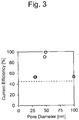
- FIG. 3 illustrates a relationship between the pore diameter and the current efficiency in the nickel film formation.
- a thickness of the nickel film obtained from the theoretical deposition amount was 5 ⁇ m.
- Example 6 The current efficiencies of Examples 6 to 10 were higher than that of Comparative Example 6. Additionally, as illustrated in FIG. 3 , the pore diameter and the current efficiency exhibited a positive correlation when the pore diameter was 50 nm or less. Meanwhile, the pore diameter and the current efficiency did not exhibit the positive correlation when the pore diameter was 50 nm or more. These results were seemingly due to an influence of capillarity being small when the pore diameter was 50 nm or more.
- Table 2 Pore Diameter [nm] Current Efficiency [%] Example 6 30 52.7 Example 7 31 52.7 Example 8 48 90 Example 9 50 98.9 Example 10 100 52.7 Comparative Example 6 1 45
Landscapes
- Chemical & Material Sciences (AREA)
- Engineering & Computer Science (AREA)
- Chemical Kinetics & Catalysis (AREA)
- Electrochemistry (AREA)
- Materials Engineering (AREA)
- Metallurgy (AREA)
- Organic Chemistry (AREA)
- Separation Using Semi-Permeable Membranes (AREA)
- Electroplating Methods And Accessories (AREA)
- Electroplating And Plating Baths Therefor (AREA)
- Cell Electrode Carriers And Collectors (AREA)
Abstract
Description
- The present disclosure relates to a film forming device for forming a metal film and a method for forming the metal film using the same.
- Conventionally, there has been widely used a plating method as a method for forming a film of metal such as tin and nickel. However, the plating method has required a rinse with water after a plating treatment, and a processing of waste liquid. Therefore,
JP 2016-169399 A JP 2016-169399 A - Further,
JP 2015-218366 A - The solid electrolyte membrane described in
JP 2016-169399 A JP 2015-218366 A - The present disclosure provides a film forming device capable of forming a metal film at a high current efficiency, in other words, at a high film forming rate and a method for forming the metal film using the film forming device.
- According to a first aspect of the present disclosure, there is provided a film forming device for forming a metal film that includes an anode, a cathode, a porous membrane, a solution container, and a power supply. The porous membrane is disposed between the anode and the cathode to be capable of contacting the cathode. The solution container defines a solution containing space between the anode and the porous membrane. The power supply applies a voltage between the anode and the cathode. The porous membrane is composed of a polyolefin chain without an ion-exchange functional group.
- According to a second aspect of the present disclosure, there is provided a method for forming a film of metal that includes applying a voltage between the anode and the cathode in the film forming device according to the first aspect in a state where the solution containing space is filled with a liquid electrolyte containing ions of the metal and the porous membrane is in contact with the cathode.
- The porous membrane used in the film forming device of the present disclosure does not have the ion-exchange functional group and therefore metal ions are allowed to pass through the inside of the porous membrane without being trapped in the membrane. Accordingly, the metal film can be formed at a high current efficiency.
-
-
FIG. 1 is a cross-sectional view schematically illustrating an example of a film forming device; -
FIG. 2 is a flowchart for a metal film forming method; and -
FIG. 3 is a graph depicting a relationship between a pore diameter and a current efficiency in nickel film formation. - As illustrated in
FIG. 1 , afilm forming device 100 according to an embodiment includes ananode 20, acathode 30, aporous membrane 60, asolution container 50 defining a solution containing space 55, and apower supply 40 applying a voltage between theanode 20 and thecathode 30. The solution containing space 55 is a space to contain a liquid electrolyte L containing metal ions. - The
anode 20 is corrosion-resistant to the liquid electrolyte L containing the metal ions and has a conductivity that allows theanode 20 to function as an electrode. For example, theanode 20 may be formed of a metal (for example, gold) having a standard oxidation-reduction potential (standard electrode potential) higher than a standard oxidation-reduction potential of the metal in the liquid electrolyte L, or a metal same as the metal in the liquid electrolyte L. A shape and an area of theanode 20 may be appropriately designed according to a shape and an area of a metal film forming area on a surface of thecathode 30. - The
cathode 30 is also corrosion-resistant to the liquid electrolyte L containing the metal ions and has a conductivity that allows thecathode 30 to function as an electrode. The metal film formed by thefilm forming device 100 is formed on the surface of thecathode 30. Therefore, a substrate to be coated with the metal film is usable as thecathode 30. - The
porous membrane 60 is disposed between theanode 20 and thecathode 30 such that theporous membrane 60 can contact thecathode 30. Theporous membrane 60 may be movable between a position where theporous membrane 60 is separated from thecathode 30 and a position where theporous membrane 60 is in contact with thecathode 30. - The
porous membrane 60 is composed of a polyolefin chain. Theporous membrane 60 may be composed of, for example, polyethylene, polypropylene, or a mixture of these substances. The polyolefin refers to all olefin polymers. The polyolefin chain may be cross-linked or non-cross-linked, may be saturated or unsaturated, or may be straight-chained or branched. Although the polyolefin chain may be substituted or unsubstituted, the polyolefin chain is without an ion-exchange functional group. In some embodiments, the polyolefin chain can be exemplified by a cross-linked or non-cross-linked polyethylene chain without a side chain. Theporous membrane 60 without the ion-exchange functional group can be disposed of without a special treatment after the use. - Here, the functional group is an atom or an atom group responsible for reactivity characteristic of an organic compound and also referred to as a functional atomic group or a functioning group. The ion exchange functional group includes both of a cation exchange functional group and an anion exchange functional group. The cation exchange functional group includes a sulfonic acid group, a sulfonimide group, a sulfone methide group, a phosphonic acid group, a carboxylic acid group, and the like. The anion exchange functional group includes a quaternary ammonium group, a quaternary pyridinium group, primary to tertiary amino groups, a pyridyl group, an imidazolyl group, and the like. A group other than the ion-exchange functional group (a non-ion-exchangeable group) includes an alkyl group, an olefin group, an acetylene group, and an aromatic group. "Without an ion-exchange functional group" means that the ion-exchange functional group is completely absent (that is, only a group other than the ion-exchange functional group is present) or present only in an amount not affecting the reactivity of the polyolefin chain. Specifically, the polyolefin chain without the ion-exchange functional group includes the polyolefin chain having the ion-exchange functional group in an amount such that a ratio of the number of oxygen atoms to that of carbon atoms in the
porous membrane 60 obtained by X-ray photoelectron spectroscopy analysis method is 0.1 or less, or 0.02 or less in some embodiments. - The presence/absence of the ion-exchange functional group can be examined by various qualitative analysis methods and quantitative analysis methods. An appropriate qualitative analysis method may be selected depending on the functional group. For example, the presence/absence of the sulfonic acid group can be examined by an alkali fusion test, a ferric hydroxamate test, or the like. The presence/absence of the carboxylic acid group can be examined by ferric hydroxamate test, pH test, or the like. Examples of the quantitative analysis method include an ultraviolet spectroscopy method, an infrared spectroscopy method, a Raman spectroscopy method, a nuclear magnetic resonance spectroscopy method, a mass analysis method, an X-ray analysis, and the like.
- The
porous membrane 60 may have a pore diameter of 20 to 2000 nm, or 27 to 1000 nm in some embodiments. The pore diameter within the range allows forming the metal film at a high current efficiency. Here, the pore diameter means a volume mean diameter of a pore diameter distribution. The pore diameter distribution can be obtained by a mercury penetration method compliant with JIS R 1655: 2003. In the mercury penetration method, a pressure is applied to cause the mercury to enter open pores of the porous membrane, and a relationship between a volume of the mercury that has entered the open pores and a pressure value applied at the time is obtained, then, based on the obtained relationship, diameters of the open pores are calculated using Washburn's equation assuming that the open pores have columnar shapes. - A solid electrolyte membrane used for the conventional solid electrolyte deposition method has flow passages formed therein, the flow passages having diameters of several nanometers respectively and referred to as ion channels. The ion channel is defined by a wall surface (surface) of the solid electrolyte membrane. On the wall surface of the solid electrolyte membrane, the ion-exchange functional group is present. When a voltage is applied between the anode and the cathode, metal ions move from the anode to the cathode via the ion channel. According to examinations by the inventor, since the ion channel has a small diameter and the ion-exchange functional group is present, the metal ions are easily trapped by the ion-exchange functional group by a Coulomb force. Therefore, transport efficiency of the metal ions inside the solid electrolyte membrane is low and the current efficiency is low as well. Meanwhile, the
porous membrane 60 used in thefilm forming device 100 of the embodiment has the pore diameter larger than that of the solid electrolyte membrane. Accordingly, the metal ions are not trapped in the pores and can move the inside of theporous membrane 60 at a high efficiency and high speed, and consequently the film of the metal can be formed at a high current efficiency. - Air permeability of the
porous membrane 60 may be 5 to 500 s/100 cm3, and 10 to 260 s/100 cm3 in some embodiments. Theporous membrane 60 having the air permeability within the range is appropriately usable for a tin film forming device. That is, the air permeability within the range allows forming a tin film at a high current efficiency. The air permeability is measured compliant with JIS L 1096-6-27-1A or ASTM-D737. - A pore percentage (porosity) of the
porous membrane 60 may be 35 to 90%, or 45 to 80% in some embodiments. The pore percentage within the range allows forming the metal film at a high current efficiency. The pore percentage is a proportion of the pores contained in a unit volume. Assuming that an apparent density (bulk density) of theporous membrane 60 as ρ1 and a true density of the porous membrane 60 (density of polymer constituting the porous membrane 60) as ρ2, a pore percentage p is expressed as p = 1 - ρ1/ρ2. The bulk density ρ1 of theporous membrane 60 can be obtained from a weight and an external volume of theporous membrane 60. The true density of theporous membrane 60 can be measured by helium gas replacement method. - A tensile strength of the
porous membrane 60 may be 750 to 3000 kgf/cm2, or 1000 to 2400 kgf/cm2 in some embodiments. The tensile strength within the range allows forming a further flat metal film. The tensile strength is measured compliant with JIS K 7127: 1999. - Tensile elongation of the
porous membrane 60 may be 5 to 85% and may be 15 to 80% in some embodiments. The tensile elongation within the range allows forming a further flat metal film. The tensile elongation is measured compliant with JIS C 2151 or ASTM D882. - A thickness of the
porous membrane 60 may be 5 to 175 µm and may be 12 to 150 µm in some embodiments. The thickness within the range allows forming the metal film at a high current efficiency. - As the
porous membrane 60, a commercially available separator for a cell is usable. In addition to being lower in cost compared with the conventional solid electrolyte membrane having the ion-exchange functional group, the commercially available separator is expected to be further reduced in cost. - A method for manufacturing the separator usable as the
porous membrane 60 mainly includes a dry method (stretch-opening method) and a wet method (phase separation method). The dry method is a method in which a film made of polymer and having a uniform composition is annealed to form a lamellar structure, then the film is uniaxially extended to cause an interface between layers in the lamellar structure to be cleaved and pores to be formed. In the porous membrane formed by the dry method, the pores linearly penetrate the porous membrane in a thickness direction of the porous membrane. Meanwhile, the wet method is a method in which a membrane formed of polymer and solvent which are microphase-separated is manufactured, and a solvent phase in this membrane is extracted and removed to cause pores to be formed. The membrane may be stretched before and/or after the extraction and removal of the solvent. In the wet method, the porous membrane having various pore structures can be manufactured by selecting a combination of the polymer and the solvent, a stretch condition, and the like. Since the pores formed by the wet method forms a three-dimensionally random and homogeneous network structure, the porous membrane obtained by the wet method has a high mechanical strength. As the porous membrane used in the film forming device according to the embodiment, the porous membrane manufactured by the wet method may be used. Since the pores in the porous membrane manufactured by the wet method form the three-dimensionally random and homogeneous network structure, the use of the porous membrane manufactured by the wet method allows suppressing a penetration and a leakage of the liquid electrolyte L containing the metal ions provided in the solution containing space 55 through theporous membrane 60. - The
solution container 50 usually has a hollow columnar shape having openings in its upper portion and lower portion. Theporous membrane 60 is disposed so as to cover the opening in the lower portion of thesolution container 50, and alid 52 is disposed so as to cover the opening in the upper portion of thesolution container 50. Theanode 20 is disposed between theporous membrane 60 and thelid 52 with separated from theporous membrane 60. Thus, the solution containing space 55 is defined between theanode 20 and theporous membrane 60. Thesolution container 50 contains the liquid electrolyte L containing the metal ions. Although theanode 20 is in contact with thelid 52 inFIG. 1 , theanode 20 and thelid 52 may be separated. In this case, the liquid electrolyte L may be also provided between theanode 20 and thelid 52. - The metal ions in the liquid electrolyte L are not specifically limited but may be ions of metal such as silver, gold, tin, and nickel. As described in examples described later, such a metal can be deposited at a high current efficiency with the
film forming device 100. The metal ions may be ions of metal having a negative standard oxidation-reduction potential, that is, ions of metal less noble than hydrogen (ions of metal whose ionization tendency is higher than that of hydrogen). With the conventional solid electrolyte deposition method using the film having the ion-exchange functional group, it is especially difficult to deposit the metal having a negative standard oxidation-reduction potential at a high current efficiency. On the other hand, thefilm forming device 100 allows the film of the metal having the negative standard oxidation-reduction potential to be formed at a high current efficiency. Examples of the metal having the negative standard oxidation-reduction potential include tin and nickel. - When the liquid electrolyte L contains tin ions, the liquid electrolyte L contains methanesulfonic acid. For example, as the liquid electrolyte (tin solution) L containing the tin ions, a solution containing tin methanesulfonate, methanesulfonic acid, isopropyl alcohol, water, and nonionic surfactant may be used. Note that an ionic liquid may be added to the liquid electrolyte L. Examples of the ionic liquid include 1-ethyl-3-methylimidazolium bromide (EMIB), trimethyl hexyl ammonium bis (trifluoromethanesulfonyl) imide (TMHA-TFSI), 1-ethyl-3-methylimidazolium bis (trifluoromethanesulfonyl) imide (EMI-TFSI), TMPA-TFSI, trimethylphenyl ammonium chloride (TMPAC), 1-ethyl-3-methylimidazolium chloride (EMIC), and 1-butyl pyridinium chloride (BPC). Furthermore, antioxidant and smoothing agent (for example, 2-mercaptobenzothiazole) may be added to the liquid electrolyte L. While the solid electrolyte membrane used in the conventional plating method may be dissolved in the organic solvent (such as methanesulfonic acid and isopropyl alcohol) contained in the liquid electrolyte in some cases, the
porous membrane 60 used in thefilm forming device 100 is not dissolved in the organic solvent in the electrolyte L. - The
power supply 40 is electrically connected to theanode 20 and thecathode 30. Thepower supply 40 generates an electric potential difference between theanode 20 and thecathode 30. - The following describes the method for forming the metal film using the film forming device 100 (see
FIG. 1 ). As depicted inFIG. 2 , the metal film forming method includes: impregnating theporous membrane 60 with ethanol (Step S1) and applying a voltage between theanode 20 and thecathode 30 to deposit the metal on the surface of the cathode 30 (Step S2). Note that impregnating theporous membrane 60 with the ethanol (Step S1) is an optional step and is not essential. The following describes the respective steps in order. - The
porous membrane 60 is impregnated with the ethanol to cause the ethanol to enter the pores in theporous membrane 60. This improves wettability of theporous membrane 60 by the liquid electrolyte L, which facilitates causing the liquid electrolyte L to enter the pores in theporous membrane 60 at the subsequent voltage applying step. A temperature of the ethanol during the impregnation is not specifically limited and may be in a temperature range equal to or higher than a freezing point of the ethanol and equal to or lower than 40°C. - The above-described solution containing space 55 in the
film forming device 100 is filled with the liquid electrolyte L containing the metal ions. Additionally, theporous membrane 60 is brought into contact with thecathode 30. In this state, a voltage is applied between theanode 20 and thecathode 30 by thepower supply 40. The metal ions in the liquid electrolyte L move in a direction from theanode 20 to thecathode 30 through theporous membrane 60. The metal ions reach an interface (surface) 30a between theporous membrane 60 and thecathode 30 and are reduced to turn into metal deposit. Thus, the metal film is formed on thecathode 30. - When the voltage is applied, the
porous membrane 60 may be heated. For example, heating of thecathode 30 allows indirect heating of theporous membrane 60, but the method for heating theporous membrane 60 is not limited to this. Heating theporous membrane 60 reduces viscosity of the ethanol in the pores in theporous membrane 60, and the liquid electrolyte L is likely to enter the pores in theporous membrane 60. The heating temperature is not specifically limited provided that the heating temperature is equal to or lower than the boiling point of the ethanol and equal to or lower than the melting point of theporous membrane 60. The heating temperature may be, for example, 35 to 65°C. - When the voltage is applied, a pressure in the solution containing space 55 may be increased, which facilitates causing the liquid electrolyte L in the solution containing space 55 to enter the pores in the
porous membrane 60. The pressure in the solution containing space 55 may be, for example, 0.5 to 3 MPa. - The voltage may be applied with the
porous membrane 60 being pressed against thecathode 30 at a predetermined pressure. This can improve the flatness of the formed metal film. For example, a pressure of 0.5 to 3 MPa may be applied. - Besides, various film forming conditions such as the applied voltage may be appropriately set depending on a formed film area, a targeted film thickness, and the like.
- When the metal ions are hydrated, the
porous membrane 60 composed of a hydrophobic polyolefin chain is less wettable by the electrolyte L containing the metal ions . - The pores in the
porous membrane 60 need not be uniform in diameter, but may vary in diameter. In the film formation using thefilm forming device 100, the pores in theporous membrane 60 are filled with the ethanol before the film formation. Increasing the pressure in the solution containing space 55 at the film formation causes the ethanol in the pores having the larger pore diameters to be pushed out and substituted with the liquid electrolyte L, which allows the liquid electrolyte L to move from the solution containing space 55 to thecathode 30 through theporous membrane 60. - While the embodiments of the present disclosure have been described in detail above, the present disclosure is not limited thereto, and can be subjected to various kinds of changes in design without departing from the spirit of the present disclosure described in the claims.
- While the following further specifically describes the present disclosure through examples and comparative examples, the present disclosure is not limited to these examples.
- A copper-sputtered substrate where a copper-sputtered film was formed on an AlSi substrate was prepared. A nickel film was formed on this copper-sputtered substrate by solid electrolyte deposition method. Conditions for the solid electrolyte deposition were as follows. A nickel film forming area was defined by disposing a polyimide tape (Kapton adhesive tape:
650R# 25 manufactured by Teraoka Seisakusho co., Ltd.) having an opening of 10 × 10 mm on the copper-sputtered substrate. The nickel film formed on the copper-sputtered substrate by the solid electrolyte deposition method had a thickness of 4 µm. The nickel solid electrolyte deposition (SED) substrate was thus obtained, and used as a substrate for forming a tin film thereon. - Anode: nickel porous body
Cathode: copper-sputtered substrate
Solid electrolyte membrane: Nafion 117 (manufactured by DuPont)
Liquid electrolyte: nickel solution obtained by mixing nickel chloride aqueous solution and acetic acid (pH 4.0)
Temperature of copper-sputtered substrate: 60°C
Pressure of pressing the solid electrolyte membrane against the copper-sputtered substrate: 1 MPa
Current density: 100 mA/cm2
Nickel film forming area: 10 mm × 10 mm - 150 g of nonionic surfactant (manufactured by Merck KGaA, copolymer of propylene oxide/ethylene oxide) was mixed with 200 g of isopropyl alcohol to obtain a mixed solution. Tin methanesulfonate was added to the mixed solution such that the mixed solution had a divalent tin ion concentration of 60 g/L, and the mixed solution was stirred. Furthermore, methanesulfonic acid was added such that the mixed solution had a free acid concentration (methanesulfonic acid concentration) of 1.0 M, and the mixed solution was stirred. Afterwards, 500 g of water was added to obtain 1000 g of tin solution.
- In each example, a commercially available separator for lithium-ion battery (manufactured by Toray Industries, Inc., product name: SETELA) was prepared as the porous membrane. Each of these porous membranes was composed of polyolefin chains. A pore diameter, air permeability, a tensile strength, a tensile elongation, a pore percentage, and a thickness of each porous membrane were as described in Table 1. A ratio of the number of oxygen atoms to that of carbon atoms in each porous membrane measured by X-ray photoelectron spectroscopic measurement device (PHI-5800 manufactured by ULVAC-PHI, Inc.) was 0.01 to 0.02. By immersing these porous membranes into ethanol, the porous membrane was impregnated with the ethanol.
- Using a nickel SED substrate as a cathode (substrate) and a tin foil (SN-443261, manufactured by Nilaco Corporation) as an anode, the substrate and the tin foil were oppositely disposed. The porous membrane was disposed between the substrate and the tin foil so as to be in contact with the substrate. A space between the porous membrane and the tin foil was filled with the tin solution. Thus, the film forming device as illustrated in
FIG. 1 was constituted. - The porous membrane was heated through heating the substrate to 40°C, and a voltage was applied between the cathode and the anode to cause a current to flow with a current density of 20 mA/cm2 while the porous membrane pressed against the substrate at 0.50 MPa. As a result, the tin was deposited on the substrate to form a tin film. The tin film forming area had a size of 10 × 10 mm. The tin film forming area was defined using the polyimide tape similarly to the nickel film formation.
- In each example, a weight of the tin deposited on the substrate was measured. By obtaining a ratio of the measured value to a theoretical deposition amount calculated from the Faraday's law, a current efficiency of the tin film formation was calculated. Table 1 depicts the obtained values of the current efficiencies. A thickness of the tin film obtained from the theoretical deposition amount was 4 µm.
- Nafion solution (manufactured by DuPont) was casted and spread on a flat plate to form an ion-exchange membrane by casting method. Using this ion-exchange membrane instead of the porous membrane, a tin film was formed similarly to Examples 1 to 5. Table 1 depicts pore diameters, air permeabilities and equivalent weights (weights of dried resin films corresponding to one equivalent of ion-exchange functional group) of the ion-exchange membranes used in Comparative Examples 1 to 5. Similarly to Examples 1 to 5, the current efficiency in each Comparative Example was obtained. Table 1 depicts the obtained values of the current efficiencies.
- Compared with Comparative Examples 1 to 5, Examples 1 to 5 where the pore diameters were within the range of 27 to 1000 nm and the air permeabilities were within the range of 10 to 260 s/100 cm3 all exhibited the high current efficiencies.
(Table 1) Pore Diameter [nm] Air Permeability [s/100 cm3] Tensile Strength [kgf/cm2] Tensile Elongation [%] Pore Percentage [%] Thickness [µm] Equivalent Weight [g/eq] Current Efficiency [%] Example 1 27 260 1500 40 47 25 - 100 Example 2 31 170 1300 80 45 100 - 95 Example 3 50 60 2303 60 55 150 - 100 Example 4 200 40 1422 15 70 12 - 100 Example 5 1000 10 1030 30 80 30 - 100 Comparative Example 1 4 1000 500 50 37 50 874 60 Comparative Example 2 4 993 385 13 39 24 812 65 Comparative Example 3 4 993 485 6 37 25 879 65 Comparative Example 4 4 1001 380 20 39 58 946 65 Comparative Example 5 4 997 330 25 40 50 735 62 - 222 g of nickel chloride hexahydrate and 124 g of nickel acetate tetrahydrate were dissolved in ion-exchange water to a total amount of 950 mL. While pH of this solution was measured, acetic acid was added dropwise such that the pH fell within the range of 3.85 to 3.95. Further, the solution was diluted with ion-exchange water to a total amount of 1000 mL. The obtained solution was used as a nickel solution.
- A porous membrane (manufactured by Toray Industries, Inc.) composed of the polyolefin chain and having the pore diameter described in Table 2 was prepared for each example. A ratio of the number of oxygen atoms to that of carbon atoms in each porous membrane measured by X-ray photoelectron spectroscopic measurement device (PHI-5800 manufactured by ULVAC-PHI, Inc) was 0.01 to 0.02. By immersing the porous membrane with ethanol, the ethanol was caused to enter the pores in the porous membrane.
- A copper plate was subjected to an activation treatment by a dip into a 10% aqueous solution of sulfuric acid at room temperature for 10 minutes. Using the copper plate as a cathode (substrate) and using a nickel porous body as an anode, the copper plate and the nickel porous body were oppositely disposed. The porous membrane was disposed between the copper plate and the nickel porous body so as to be in contact with the copper plate. A space between the porous membrane and the nickel porous body was filled with the nickel solution. Thus, the film forming device as illustrated in
FIG. 1 was constituted. - Next, the porous membrane was heated through heating the copper plate to 60°C, and a voltage was applied between the cathode and the anode to cause a current to flow with a current density of 75 mA/cm2 while the porous membrane pressed against the copper plate at 1.0 MPa. As a result, the nickel was deposited on the copper plate to form a nickel film. The nickel film forming area had a size of 10 × 20 mm. The nickel film forming area was defined using the polyimide tape similarly to Examples 1 to 5.
- In each example, a weight of the nickel deposited on the copper plate was measured. By obtaining a ratio of the measured value to a theoretical deposition amount calculated from the Faraday's law, a current efficiency of the nickel film formation was calculated. Table 2 depicts the obtained values of the current efficiencies.
FIG. 3 illustrates a relationship between the pore diameter and the current efficiency in the nickel film formation. A thickness of the nickel film obtained from the theoretical deposition amount was 5 µm. - Using an ion-exchange membrane (product name: Nafion) manufactured by DuPont instead of the porous membrane, a nickel film was formed similarly to Examples 6 to 10. The ion-exchange membrane had a pore diameter of 1 nm. Similarly to Examples 6 to 10, a current efficiency of the nickel film formation in Comparative Example 6 was obtained. Table 2 depicts the results.
FIG. 3 indicates the current efficiency of Comparative Example 6 by the dashed line. - The current efficiencies of Examples 6 to 10 were higher than that of Comparative Example 6. Additionally, as illustrated in
FIG. 3 , the pore diameter and the current efficiency exhibited a positive correlation when the pore diameter was 50 nm or less. Meanwhile, the pore diameter and the current efficiency did not exhibit the positive correlation when the pore diameter was 50 nm or more. These results were seemingly due to an influence of capillarity being small when the pore diameter was 50 nm or more.(Table 2) Pore Diameter [nm] Current Efficiency [%] Example 6 30 52.7 Example 7 31 52.7 Example 8 48 90 Example 9 50 98.9 Example 10 100 52.7 Comparative Example 6 1 45 -
- 20
- Anode
- 30
- Cathode
- 40
- Power supply
- 50
- Solution container
- 55
- Solution containing space
- 60
- Porous membrane
- 100
- Film forming device
- L
- Liquid electrolyte
Claims (8)
- A film forming device (100) for forming a metal film comprising:an anode (20);a cathode (30);a porous membrane (60) disposed between the anode (20) and the cathode (30) to be capable of contacting the cathode (30);a solution container (50) defining a solution containing space between the anode (20) and the porous membrane (60); anda power supply (40) applying a voltage between the anode (20) and the cathode (30),wherein the porous membrane (60) is composed of a polyolefin chain without an ion-exchange functional group.
- The film forming device (100) according to claim 1,
wherein the porous membrane (60) has a pore diameter within a range of 20 to 2000 nm. - The film forming device (100) according to claim 1 or 2,
wherein the porous membrane (60) has air permeability within a range of 5 to 500 s/100 cm3. - A method for forming a film of metal comprising
applying a voltage between the anode (20) and the cathode (30) in the film forming device (100) according to any one of claims 1 to 3 in a state where the solution containing space is filled with a liquid electrolyte (L) containing ions of the metal and the porous membrane (60) is in contact with the cathode (30). - The method according to claim 4,
wherein the metal has a negative standard oxidation-reduction potential. - The method according to claim 4 or 5, further comprisingimpregnating the porous membrane (60) with ethanol,wherein the voltage is applied between the anode (20) and the cathode (30) while the porous membrane (60) is heated.
- The method according to any one of claims 4 to 6,
wherein the metal is tin or nickel. - The method according to claim 7,
wherein the metal is the tin, and the liquid electrolyte (L) contains methanesulfonic acid.
Applications Claiming Priority (1)
| Application Number | Priority Date | Filing Date | Title |
|---|---|---|---|
| JP2018236058A JP2020097764A (en) | 2018-12-18 | 2018-12-18 | Film forming device, and method of forming metal film using the same |
Publications (2)
| Publication Number | Publication Date |
|---|---|
| EP3680367A2 true EP3680367A2 (en) | 2020-07-15 |
| EP3680367A3 EP3680367A3 (en) | 2020-09-30 |
Family
ID=68382196
Family Applications (1)
| Application Number | Title | Priority Date | Filing Date |
|---|---|---|---|
| EP19205455.9A Withdrawn EP3680367A3 (en) | 2018-12-18 | 2019-10-25 | Film forming device and method for forming metal film using the same |
Country Status (5)
| Country | Link |
|---|---|
| US (1) | US20200190685A1 (en) |
| EP (1) | EP3680367A3 (en) |
| JP (1) | JP2020097764A (en) |
| KR (1) | KR20200075735A (en) |
| CN (1) | CN111334840A (en) |
Cited By (1)
| Publication number | Priority date | Publication date | Assignee | Title |
|---|---|---|---|---|
| DE102021114445B4 (en) * | 2020-07-29 | 2025-07-03 | Toyota Jidosha Kabushiki Kaisha | Process for forming a silver film |
Families Citing this family (1)
| Publication number | Priority date | Publication date | Assignee | Title |
|---|---|---|---|---|
| JP7661846B2 (en) * | 2021-09-07 | 2025-04-15 | トヨタ自動車株式会社 | Copper film deposition method |
Citations (2)
| Publication number | Priority date | Publication date | Assignee | Title |
|---|---|---|---|---|
| JP2015218366A (en) | 2014-05-19 | 2015-12-07 | 株式会社豊田中央研究所 | Electroplating cell and metal film manufacturing method |
| JP2016169399A (en) | 2015-03-11 | 2016-09-23 | トヨタ自動車株式会社 | Apparatus and method for film deposition of metal coating |
Family Cites Families (9)
| Publication number | Priority date | Publication date | Assignee | Title |
|---|---|---|---|---|
| US6126798A (en) * | 1997-11-13 | 2000-10-03 | Novellus Systems, Inc. | Electroplating anode including membrane partition system and method of preventing passivation of same |
| JP2004353061A (en) * | 2003-05-30 | 2004-12-16 | Ebara Corp | Electrolytic treatment method and apparatus |
| US9404194B2 (en) * | 2010-12-01 | 2016-08-02 | Novellus Systems, Inc. | Electroplating apparatus and process for wafer level packaging |
| US10047452B2 (en) * | 2012-02-23 | 2018-08-14 | Toyota Jidosha Kabushiki Kaisha | Film formation device and film formation method for forming metal film |
| BR112016009844B1 (en) * | 2013-11-14 | 2022-02-22 | Toyota Jidosha Kabushiki Kaisha | METALLIC FILM FILM FORMING APPARATUS AND METALLIC FILM FILM FORMING METHOD |
| JP5938426B2 (en) * | 2014-02-04 | 2016-06-22 | 株式会社豊田中央研究所 | Electroplating cell and metal film manufacturing method |
| JP6435546B2 (en) * | 2014-10-17 | 2018-12-12 | ディップソール株式会社 | Copper-nickel alloy electroplating equipment |
| JP6548960B2 (en) * | 2015-06-02 | 2019-07-24 | 株式会社豊田中央研究所 | Electroplating cell and method of manufacturing metal film |
| JP6447575B2 (en) * | 2016-05-23 | 2019-01-09 | トヨタ自動車株式会社 | Metal film forming method and film forming apparatus |
-
2018
- 2018-12-18 JP JP2018236058A patent/JP2020097764A/en not_active Withdrawn
-
2019
- 2019-10-21 US US16/658,163 patent/US20200190685A1/en not_active Abandoned
- 2019-10-25 EP EP19205455.9A patent/EP3680367A3/en not_active Withdrawn
- 2019-11-15 KR KR1020190146365A patent/KR20200075735A/en not_active Ceased
- 2019-12-17 CN CN201911300780.0A patent/CN111334840A/en active Pending
Patent Citations (2)
| Publication number | Priority date | Publication date | Assignee | Title |
|---|---|---|---|---|
| JP2015218366A (en) | 2014-05-19 | 2015-12-07 | 株式会社豊田中央研究所 | Electroplating cell and metal film manufacturing method |
| JP2016169399A (en) | 2015-03-11 | 2016-09-23 | トヨタ自動車株式会社 | Apparatus and method for film deposition of metal coating |
Cited By (1)
| Publication number | Priority date | Publication date | Assignee | Title |
|---|---|---|---|---|
| DE102021114445B4 (en) * | 2020-07-29 | 2025-07-03 | Toyota Jidosha Kabushiki Kaisha | Process for forming a silver film |
Also Published As
| Publication number | Publication date |
|---|---|
| US20200190685A1 (en) | 2020-06-18 |
| CN111334840A (en) | 2020-06-26 |
| JP2020097764A (en) | 2020-06-25 |
| KR20200075735A (en) | 2020-06-26 |
| EP3680367A3 (en) | 2020-09-30 |
Similar Documents
| Publication | Publication Date | Title |
|---|---|---|
| CN112886135B (en) | Rechargeable battery with anionically conductive polymer | |
| Lee et al. | Layered composite membranes based on porous PVDF coated with a thin, dense PBI layer for vanadium redox flow batteries | |
| KR102466595B1 (en) | Highly reinforced ionomer membranes for high selectivity and high strength | |
| Lu et al. | Layer-by-layer self-assembly of Nafion–[CS–PWA] composite membranes with suppressed vanadium ion crossover for vanadium redox flow battery applications | |
| AU2017224129B2 (en) | Composite membranes for flow batteries | |
| US12214319B2 (en) | Lithium ion conducting membranes | |
| US8669011B2 (en) | Nucleation and growth of tin particles into three dimensional composite active anode for lithium high capacity energy storage device | |
| Kim et al. | A hydrocarbon/Nafion bilayer membrane with a mechanical nano-fastener for vanadium redox flow batteries | |
| US11201324B2 (en) | Production of lithium via electrodeposition | |
| Waqas et al. | A robust bi-layer separator with Lewis acid-base interaction for high-rate capacity lithium-ion batteries | |
| JP2017114122A (en) | Reinforced composite membrane and method for producing the same | |
| US20120295169A1 (en) | Air battery and electrode | |
| US9446350B2 (en) | Gas decomposition apparatus and method for decomposing gas | |
| US20160372729A1 (en) | Laminated Composite Separator, Method and Application | |
| EP3680367A2 (en) | Film forming device and method for forming metal film using the same | |
| US9331353B2 (en) | Proton-conducting composite membrane for fuel cells | |
| WO2017087907A1 (en) | Transition metal depositi0n and oxidation on symmetric metal oxide electrodes for storage application | |
| EP3063821B1 (en) | Cation-conductive conformal ultrathin polymer electrolytes | |
| CN111883825B (en) | Polymer electrolyte and preparation method, lithium metal battery | |
| CN114059111B (en) | How to form silver coating | |
| CN115999383B (en) | Ultrathin b-oriented ZSM-5 zeolite molecular sieve membrane, preparation method and application thereof in vanadium oxide flow battery | |
| US11945722B2 (en) | Electrochemical method for the production of graphene composites and cell for conducting the same | |
| Nguyen et al. | Ultrathin Yet Effective: 90-nm ZnF2 Layer for Stabilizing Zinc-Metal Batteries | |
| KR20230063778A (en) | Preparation method of perfluorinated ionomer memebrane having highly ordered ion channel and uses thereof |
Legal Events
| Date | Code | Title | Description |
|---|---|---|---|
| PUAI | Public reference made under article 153(3) epc to a published international application that has entered the european phase |
Free format text: ORIGINAL CODE: 0009012 |
|
| STAA | Information on the status of an ep patent application or granted ep patent |
Free format text: STATUS: REQUEST FOR EXAMINATION WAS MADE |
|
| 17P | Request for examination filed |
Effective date: 20191025 |
|
| AK | Designated contracting states |
Kind code of ref document: A2 Designated state(s): AL AT BE BG CH CY CZ DE DK EE ES FI FR GB GR HR HU IE IS IT LI LT LU LV MC MK MT NL NO PL PT RO RS SE SI SK SM TR |
|
| AX | Request for extension of the european patent |
Extension state: BA ME |
|
| PUAL | Search report despatched |
Free format text: ORIGINAL CODE: 0009013 |
|
| AK | Designated contracting states |
Kind code of ref document: A3 Designated state(s): AL AT BE BG CH CY CZ DE DK EE ES FI FR GB GR HR HU IE IS IT LI LT LU LV MC MK MT NL NO PL PT RO RS SE SI SK SM TR |
|
| AX | Request for extension of the european patent |
Extension state: BA ME |
|
| RIC1 | Information provided on ipc code assigned before grant |
Ipc: C25D 3/12 20060101ALN20200826BHEP Ipc: C25D 17/00 20060101AFI20200826BHEP Ipc: C25D 3/30 20060101ALI20200826BHEP |
|
| STAA | Information on the status of an ep patent application or granted ep patent |
Free format text: STATUS: THE APPLICATION HAS BEEN WITHDRAWN |
|
| 18W | Application withdrawn |
Effective date: 20211208 |