EP3680123B1 - Method for controlling a railway vehicle, a controller and a railway vehicle - Google Patents
Method for controlling a railway vehicle, a controller and a railway vehicle Download PDFInfo
- Publication number
- EP3680123B1 EP3680123B1 EP19305032.5A EP19305032A EP3680123B1 EP 3680123 B1 EP3680123 B1 EP 3680123B1 EP 19305032 A EP19305032 A EP 19305032A EP 3680123 B1 EP3680123 B1 EP 3680123B1
- Authority
- EP
- European Patent Office
- Prior art keywords
- torque
- railway vehicle
- controller
- est
- motor controller
- Prior art date
- Legal status (The legal status is an assumption and is not a legal conclusion. Google has not performed a legal analysis and makes no representation as to the accuracy of the status listed.)
- Active
Links
Images


Classifications
-
- B—PERFORMING OPERATIONS; TRANSPORTING
- B60—VEHICLES IN GENERAL
- B60L—PROPULSION OF ELECTRICALLY-PROPELLED VEHICLES; SUPPLYING ELECTRIC POWER FOR AUXILIARY EQUIPMENT OF ELECTRICALLY-PROPELLED VEHICLES; ELECTRODYNAMIC BRAKE SYSTEMS FOR VEHICLES IN GENERAL; MAGNETIC SUSPENSION OR LEVITATION FOR VEHICLES; MONITORING OPERATING VARIABLES OF ELECTRICALLY-PROPELLED VEHICLES; ELECTRIC SAFETY DEVICES FOR ELECTRICALLY-PROPELLED VEHICLES
- B60L3/00—Electric devices on electrically-propelled vehicles for safety purposes; Monitoring operating variables, e.g. speed, deceleration or energy consumption
- B60L3/10—Indicating wheel slip ; Correction of wheel slip
- B60L3/106—Indicating wheel slip ; Correction of wheel slip for maintaining or recovering the adhesion of the drive wheels
- B60L3/108—Indicating wheel slip ; Correction of wheel slip for maintaining or recovering the adhesion of the drive wheels whilst braking, i.e. ABS
-
- B—PERFORMING OPERATIONS; TRANSPORTING
- B60—VEHICLES IN GENERAL
- B60L—PROPULSION OF ELECTRICALLY-PROPELLED VEHICLES; SUPPLYING ELECTRIC POWER FOR AUXILIARY EQUIPMENT OF ELECTRICALLY-PROPELLED VEHICLES; ELECTRODYNAMIC BRAKE SYSTEMS FOR VEHICLES IN GENERAL; MAGNETIC SUSPENSION OR LEVITATION FOR VEHICLES; MONITORING OPERATING VARIABLES OF ELECTRICALLY-PROPELLED VEHICLES; ELECTRIC SAFETY DEVICES FOR ELECTRICALLY-PROPELLED VEHICLES
- B60L15/00—Methods, circuits, or devices for controlling the traction-motor speed of electrically-propelled vehicles
- B60L15/20—Methods, circuits, or devices for controlling the traction-motor speed of electrically-propelled vehicles for control of the vehicle or its driving motor to achieve a desired performance, e.g. speed, torque, programmed variation of speed
-
- B—PERFORMING OPERATIONS; TRANSPORTING
- B60—VEHICLES IN GENERAL
- B60L—PROPULSION OF ELECTRICALLY-PROPELLED VEHICLES; SUPPLYING ELECTRIC POWER FOR AUXILIARY EQUIPMENT OF ELECTRICALLY-PROPELLED VEHICLES; ELECTRODYNAMIC BRAKE SYSTEMS FOR VEHICLES IN GENERAL; MAGNETIC SUSPENSION OR LEVITATION FOR VEHICLES; MONITORING OPERATING VARIABLES OF ELECTRICALLY-PROPELLED VEHICLES; ELECTRIC SAFETY DEVICES FOR ELECTRICALLY-PROPELLED VEHICLES
- B60L15/00—Methods, circuits, or devices for controlling the traction-motor speed of electrically-propelled vehicles
- B60L15/20—Methods, circuits, or devices for controlling the traction-motor speed of electrically-propelled vehicles for control of the vehicle or its driving motor to achieve a desired performance, e.g. speed, torque, programmed variation of speed
- B60L15/2009—Methods, circuits, or devices for controlling the traction-motor speed of electrically-propelled vehicles for control of the vehicle or its driving motor to achieve a desired performance, e.g. speed, torque, programmed variation of speed for braking
-
- B—PERFORMING OPERATIONS; TRANSPORTING
- B60—VEHICLES IN GENERAL
- B60L—PROPULSION OF ELECTRICALLY-PROPELLED VEHICLES; SUPPLYING ELECTRIC POWER FOR AUXILIARY EQUIPMENT OF ELECTRICALLY-PROPELLED VEHICLES; ELECTRODYNAMIC BRAKE SYSTEMS FOR VEHICLES IN GENERAL; MAGNETIC SUSPENSION OR LEVITATION FOR VEHICLES; MONITORING OPERATING VARIABLES OF ELECTRICALLY-PROPELLED VEHICLES; ELECTRIC SAFETY DEVICES FOR ELECTRICALLY-PROPELLED VEHICLES
- B60L9/00—Electric propulsion with power supply external to the vehicle
-
- B—PERFORMING OPERATIONS; TRANSPORTING
- B60—VEHICLES IN GENERAL
- B60L—PROPULSION OF ELECTRICALLY-PROPELLED VEHICLES; SUPPLYING ELECTRIC POWER FOR AUXILIARY EQUIPMENT OF ELECTRICALLY-PROPELLED VEHICLES; ELECTRODYNAMIC BRAKE SYSTEMS FOR VEHICLES IN GENERAL; MAGNETIC SUSPENSION OR LEVITATION FOR VEHICLES; MONITORING OPERATING VARIABLES OF ELECTRICALLY-PROPELLED VEHICLES; ELECTRIC SAFETY DEVICES FOR ELECTRICALLY-PROPELLED VEHICLES
- B60L9/00—Electric propulsion with power supply external to the vehicle
- B60L9/16—Electric propulsion with power supply external to the vehicle using AC induction motors
-
- B—PERFORMING OPERATIONS; TRANSPORTING
- B61—RAILWAYS
- B61C—LOCOMOTIVES; MOTOR RAILCARS
- B61C15/00—Maintaining or augmenting the starting or braking power by auxiliary devices and measures; Preventing wheel slippage; Controlling distribution of tractive effort between driving wheels
- B61C15/08—Preventing wheel slippage
-
- B—PERFORMING OPERATIONS; TRANSPORTING
- B60—VEHICLES IN GENERAL
- B60L—PROPULSION OF ELECTRICALLY-PROPELLED VEHICLES; SUPPLYING ELECTRIC POWER FOR AUXILIARY EQUIPMENT OF ELECTRICALLY-PROPELLED VEHICLES; ELECTRODYNAMIC BRAKE SYSTEMS FOR VEHICLES IN GENERAL; MAGNETIC SUSPENSION OR LEVITATION FOR VEHICLES; MONITORING OPERATING VARIABLES OF ELECTRICALLY-PROPELLED VEHICLES; ELECTRIC SAFETY DEVICES FOR ELECTRICALLY-PROPELLED VEHICLES
- B60L2200/00—Type of vehicles
- B60L2200/26—Rail vehicles
-
- B—PERFORMING OPERATIONS; TRANSPORTING
- B60—VEHICLES IN GENERAL
- B60L—PROPULSION OF ELECTRICALLY-PROPELLED VEHICLES; SUPPLYING ELECTRIC POWER FOR AUXILIARY EQUIPMENT OF ELECTRICALLY-PROPELLED VEHICLES; ELECTRODYNAMIC BRAKE SYSTEMS FOR VEHICLES IN GENERAL; MAGNETIC SUSPENSION OR LEVITATION FOR VEHICLES; MONITORING OPERATING VARIABLES OF ELECTRICALLY-PROPELLED VEHICLES; ELECTRIC SAFETY DEVICES FOR ELECTRICALLY-PROPELLED VEHICLES
- B60L2220/00—Electrical machine types; Structures or applications thereof
- B60L2220/10—Electrical machine types
- B60L2220/12—Induction machines
-
- B—PERFORMING OPERATIONS; TRANSPORTING
- B60—VEHICLES IN GENERAL
- B60L—PROPULSION OF ELECTRICALLY-PROPELLED VEHICLES; SUPPLYING ELECTRIC POWER FOR AUXILIARY EQUIPMENT OF ELECTRICALLY-PROPELLED VEHICLES; ELECTRODYNAMIC BRAKE SYSTEMS FOR VEHICLES IN GENERAL; MAGNETIC SUSPENSION OR LEVITATION FOR VEHICLES; MONITORING OPERATING VARIABLES OF ELECTRICALLY-PROPELLED VEHICLES; ELECTRIC SAFETY DEVICES FOR ELECTRICALLY-PROPELLED VEHICLES
- B60L2220/00—Electrical machine types; Structures or applications thereof
- B60L2220/10—Electrical machine types
- B60L2220/14—Synchronous machines
-
- B—PERFORMING OPERATIONS; TRANSPORTING
- B60—VEHICLES IN GENERAL
- B60L—PROPULSION OF ELECTRICALLY-PROPELLED VEHICLES; SUPPLYING ELECTRIC POWER FOR AUXILIARY EQUIPMENT OF ELECTRICALLY-PROPELLED VEHICLES; ELECTRODYNAMIC BRAKE SYSTEMS FOR VEHICLES IN GENERAL; MAGNETIC SUSPENSION OR LEVITATION FOR VEHICLES; MONITORING OPERATING VARIABLES OF ELECTRICALLY-PROPELLED VEHICLES; ELECTRIC SAFETY DEVICES FOR ELECTRICALLY-PROPELLED VEHICLES
- B60L2220/00—Electrical machine types; Structures or applications thereof
- B60L2220/10—Electrical machine types
- B60L2220/16—DC brushless machines
-
- B—PERFORMING OPERATIONS; TRANSPORTING
- B60—VEHICLES IN GENERAL
- B60L—PROPULSION OF ELECTRICALLY-PROPELLED VEHICLES; SUPPLYING ELECTRIC POWER FOR AUXILIARY EQUIPMENT OF ELECTRICALLY-PROPELLED VEHICLES; ELECTRODYNAMIC BRAKE SYSTEMS FOR VEHICLES IN GENERAL; MAGNETIC SUSPENSION OR LEVITATION FOR VEHICLES; MONITORING OPERATING VARIABLES OF ELECTRICALLY-PROPELLED VEHICLES; ELECTRIC SAFETY DEVICES FOR ELECTRICALLY-PROPELLED VEHICLES
- B60L2240/00—Control parameters of input or output; Target parameters
- B60L2240/10—Vehicle control parameters
- B60L2240/12—Speed
-
- B—PERFORMING OPERATIONS; TRANSPORTING
- B60—VEHICLES IN GENERAL
- B60L—PROPULSION OF ELECTRICALLY-PROPELLED VEHICLES; SUPPLYING ELECTRIC POWER FOR AUXILIARY EQUIPMENT OF ELECTRICALLY-PROPELLED VEHICLES; ELECTRODYNAMIC BRAKE SYSTEMS FOR VEHICLES IN GENERAL; MAGNETIC SUSPENSION OR LEVITATION FOR VEHICLES; MONITORING OPERATING VARIABLES OF ELECTRICALLY-PROPELLED VEHICLES; ELECTRIC SAFETY DEVICES FOR ELECTRICALLY-PROPELLED VEHICLES
- B60L2240/00—Control parameters of input or output; Target parameters
- B60L2240/40—Drive Train control parameters
- B60L2240/42—Drive Train control parameters related to electric machines
- B60L2240/421—Speed
-
- B—PERFORMING OPERATIONS; TRANSPORTING
- B60—VEHICLES IN GENERAL
- B60L—PROPULSION OF ELECTRICALLY-PROPELLED VEHICLES; SUPPLYING ELECTRIC POWER FOR AUXILIARY EQUIPMENT OF ELECTRICALLY-PROPELLED VEHICLES; ELECTRODYNAMIC BRAKE SYSTEMS FOR VEHICLES IN GENERAL; MAGNETIC SUSPENSION OR LEVITATION FOR VEHICLES; MONITORING OPERATING VARIABLES OF ELECTRICALLY-PROPELLED VEHICLES; ELECTRIC SAFETY DEVICES FOR ELECTRICALLY-PROPELLED VEHICLES
- B60L2240/00—Control parameters of input or output; Target parameters
- B60L2240/40—Drive Train control parameters
- B60L2240/42—Drive Train control parameters related to electric machines
- B60L2240/423—Torque
-
- B—PERFORMING OPERATIONS; TRANSPORTING
- B60—VEHICLES IN GENERAL
- B60L—PROPULSION OF ELECTRICALLY-PROPELLED VEHICLES; SUPPLYING ELECTRIC POWER FOR AUXILIARY EQUIPMENT OF ELECTRICALLY-PROPELLED VEHICLES; ELECTRODYNAMIC BRAKE SYSTEMS FOR VEHICLES IN GENERAL; MAGNETIC SUSPENSION OR LEVITATION FOR VEHICLES; MONITORING OPERATING VARIABLES OF ELECTRICALLY-PROPELLED VEHICLES; ELECTRIC SAFETY DEVICES FOR ELECTRICALLY-PROPELLED VEHICLES
- B60L2240/00—Control parameters of input or output; Target parameters
- B60L2240/40—Drive Train control parameters
- B60L2240/42—Drive Train control parameters related to electric machines
- B60L2240/427—Voltage
-
- B—PERFORMING OPERATIONS; TRANSPORTING
- B60—VEHICLES IN GENERAL
- B60L—PROPULSION OF ELECTRICALLY-PROPELLED VEHICLES; SUPPLYING ELECTRIC POWER FOR AUXILIARY EQUIPMENT OF ELECTRICALLY-PROPELLED VEHICLES; ELECTRODYNAMIC BRAKE SYSTEMS FOR VEHICLES IN GENERAL; MAGNETIC SUSPENSION OR LEVITATION FOR VEHICLES; MONITORING OPERATING VARIABLES OF ELECTRICALLY-PROPELLED VEHICLES; ELECTRIC SAFETY DEVICES FOR ELECTRICALLY-PROPELLED VEHICLES
- B60L2240/00—Control parameters of input or output; Target parameters
- B60L2240/40—Drive Train control parameters
- B60L2240/42—Drive Train control parameters related to electric machines
- B60L2240/429—Current
-
- B—PERFORMING OPERATIONS; TRANSPORTING
- B60—VEHICLES IN GENERAL
- B60L—PROPULSION OF ELECTRICALLY-PROPELLED VEHICLES; SUPPLYING ELECTRIC POWER FOR AUXILIARY EQUIPMENT OF ELECTRICALLY-PROPELLED VEHICLES; ELECTRODYNAMIC BRAKE SYSTEMS FOR VEHICLES IN GENERAL; MAGNETIC SUSPENSION OR LEVITATION FOR VEHICLES; MONITORING OPERATING VARIABLES OF ELECTRICALLY-PROPELLED VEHICLES; ELECTRIC SAFETY DEVICES FOR ELECTRICALLY-PROPELLED VEHICLES
- B60L2240/00—Control parameters of input or output; Target parameters
- B60L2240/40—Drive Train control parameters
- B60L2240/46—Drive Train control parameters related to wheels
- B60L2240/465—Slip
-
- B—PERFORMING OPERATIONS; TRANSPORTING
- B60—VEHICLES IN GENERAL
- B60L—PROPULSION OF ELECTRICALLY-PROPELLED VEHICLES; SUPPLYING ELECTRIC POWER FOR AUXILIARY EQUIPMENT OF ELECTRICALLY-PROPELLED VEHICLES; ELECTRODYNAMIC BRAKE SYSTEMS FOR VEHICLES IN GENERAL; MAGNETIC SUSPENSION OR LEVITATION FOR VEHICLES; MONITORING OPERATING VARIABLES OF ELECTRICALLY-PROPELLED VEHICLES; ELECTRIC SAFETY DEVICES FOR ELECTRICALLY-PROPELLED VEHICLES
- B60L2240/00—Control parameters of input or output; Target parameters
- B60L2240/60—Navigation input
- B60L2240/64—Road conditions
- B60L2240/647—Surface situation of road, e.g. type of paving
-
- Y—GENERAL TAGGING OF NEW TECHNOLOGICAL DEVELOPMENTS; GENERAL TAGGING OF CROSS-SECTIONAL TECHNOLOGIES SPANNING OVER SEVERAL SECTIONS OF THE IPC; TECHNICAL SUBJECTS COVERED BY FORMER USPC CROSS-REFERENCE ART COLLECTIONS [XRACs] AND DIGESTS
- Y02—TECHNOLOGIES OR APPLICATIONS FOR MITIGATION OR ADAPTATION AGAINST CLIMATE CHANGE
- Y02T—CLIMATE CHANGE MITIGATION TECHNOLOGIES RELATED TO TRANSPORTATION
- Y02T10/00—Road transport of goods or passengers
- Y02T10/60—Other road transportation technologies with climate change mitigation effect
- Y02T10/64—Electric machine technologies in electromobility
-
- Y—GENERAL TAGGING OF NEW TECHNOLOGICAL DEVELOPMENTS; GENERAL TAGGING OF CROSS-SECTIONAL TECHNOLOGIES SPANNING OVER SEVERAL SECTIONS OF THE IPC; TECHNICAL SUBJECTS COVERED BY FORMER USPC CROSS-REFERENCE ART COLLECTIONS [XRACs] AND DIGESTS
- Y02—TECHNOLOGIES OR APPLICATIONS FOR MITIGATION OR ADAPTATION AGAINST CLIMATE CHANGE
- Y02T—CLIMATE CHANGE MITIGATION TECHNOLOGIES RELATED TO TRANSPORTATION
- Y02T10/00—Road transport of goods or passengers
- Y02T10/60—Other road transportation technologies with climate change mitigation effect
- Y02T10/72—Electric energy management in electromobility
-
- Y—GENERAL TAGGING OF NEW TECHNOLOGICAL DEVELOPMENTS; GENERAL TAGGING OF CROSS-SECTIONAL TECHNOLOGIES SPANNING OVER SEVERAL SECTIONS OF THE IPC; TECHNICAL SUBJECTS COVERED BY FORMER USPC CROSS-REFERENCE ART COLLECTIONS [XRACs] AND DIGESTS
- Y02—TECHNOLOGIES OR APPLICATIONS FOR MITIGATION OR ADAPTATION AGAINST CLIMATE CHANGE
- Y02T—CLIMATE CHANGE MITIGATION TECHNOLOGIES RELATED TO TRANSPORTATION
- Y02T90/00—Enabling technologies or technologies with a potential or indirect contribution to GHG emissions mitigation
- Y02T90/10—Technologies relating to charging of electric vehicles
- Y02T90/16—Information or communication technologies improving the operation of electric vehicles
Definitions
- the present invention concerns a method for controlling a railway vehicle comprising a motor controller for an electric machine acting on at least one wheel of the railway vehicle.
- the present invention relates to a torque controller for a railway vehicle comprising a motor controller for an electric machine acting on at least one wheel of the railway vehicle.
- the present invention relates to a railway vehicle comprising such a controller and a computer program product.
- WO 2017/175119 A1 relates to a method for calculating the speed of a railway vehicle and for controlling the torque.
- Anti-slip/slide devices perform an anti-blocking control (ABC) function usually maintaining effort at the limit of adherence by means of threshold of speed, acceleration and jerk.
- ABSC anti-blocking control
- the first strategy is aimed to cancel ("kill") the slide in order to operate as much as possible in the micro-slip range of the adherence curve.
- the first strategy requires quick torque modulation producing a periodical triangular torque reference profile.
- the second is aimed to "keep” the slide on a constant value in order to benefit of the cleaning effect due to wheel surface temperature increase (adherence regeneration).
- the second strategy, regulating the slide on a constant value should apply a less variable effort but, adopting pre-defined thresholds of wheel slip/slide, acceleration and jerk, in real applications sometimes wheel effort and speed can exhibit undesired oscillations.
- Object of the invention is to provide a reference torque as constant as possible in order to avoid the excitation of possible resonance of the transmissions and to follow the varying conditions of the rail.
- a method for controlling a railway vehicle comprising a motor controller for an electric machine according to claim 1 is provided.
- the present invention may include one or more of the following features:
- a torque controller for a railway vehicle according to claim 8 is provided.
- a railway vehicle comprising a motor controller for an electric machine acting on at least one wheel of the railway vehicle, a plurality of wheels, one or more wheel sensors for determining the rotational speed of the wheels, wherein the railway vehicle comprises a torque controller according to an embodiment disclosed herein.
- the present invention relates to a computer program product, comprising commands for implementing the method according to an embodiment disclosed herein when loaded and executed on a processor.
- the electrical machine 5 is a permanent magnet machine. In another embodiment the electrical machine is an asynchronous motor.
- the railway vehicle comprises further a central controller 9, which is adapted to receive the commands of a driver or another system, which determines the reference speed and/or the reference torque for the wheels 3 T ref .
- T ref corresponds to the torque request.
- the other system may be a train protection system, like the European Train Control System.
- the railway vehicle 1 includes at least one speed sensor 12 for determining the speed v of the railway vehicle 1.
- the speed v of the railway vehicle 1 can be estimated by an elaboration of the measured wheels speed performed by the ABC device.
- the railway vehicle 1 has one or more wheel sensors 14 for determining the rotational speed w of the wheels 3.
- the railway vehicle 1 includes a torque controller 16.
- the torque controller is, according to an embodiment, an anti-blocking control (ABC) device.
- the torque controller 16 is adapted to calculate a reference torque, which is then provided to the motor controller 7.
- the torque controller 16 is connected to the motor controller 7 to receive a calculated motor torque.
- the torque controller 16 is connected to the main controller 9 to receive the reference torque T ref .
- the torque controller 16 is directly or indirectly connected to the speed sensor 12 and the wheel sensor 14 for receiving data for determining the actual speed of the railway vehicle 1 and the rotational speed of the wheels 3.
- the torque controller 16 is adapted to use the output of the one or more wheel sensors 14 to estimate the speed v of the railway vehicle 1.
- the central controller 9, the motor controller 7 and/or the torque controller 16 are provided in a single controller or two or more controllers.
- the torque controller 16 is provided to prevent a sliding or slipping of the wheels 3.
- the torque controller 16 is adapted to calculate a maximal adherence between the wheels 3 and the rail 2.
- FIG. 2 shows in more detail the blocks provided in the torque controller 16.
- a first block 20 is provided to estimate a maximal adherence ( ⁇ est ) of the railway vehicle 1, in particular the wheels 3, on the rail. Further, the first block 20 calculates the optimal wheel speed ⁇ 0 , the slip ⁇ and the absolute slip ⁇ Absolute . The first block 20 also provides the (actual) wheel speed w as an output.
- the adherence ⁇ of a wheel on the rail depends on the wheel/rail surface conditions (e.g. dry or wet) and on the speed v of the railway vehicle.
- the slip or slide depends on the adherence ⁇ , on the rotational speed w of the wheels 3, on the speed v of the railway vehicle 1 and on the actual motoring or braking effort.
- the slip or slide is the difference between the tangential speed of the wheel (at the contact point on the rail) and the speed v of the railway vehicle 1.
- a second block 22 is adapted to calculate the torque T contr to be provided by the electrical machine 5 to the wheel 3. According to embodiments, the second block 22 implements the control as such.
- the torque of the wheel 3 depends on the torque of the electrical machine 5.
- the output torque T contr of the second block 22 is adapted to be provided to the motor controller 7.
- the second block 22 is adapted to control the torque based on the estimated maximal adherence ⁇ est of the first block 20, the slip ⁇ and the reference torque T ref provided by the central controller 9.
- the torque control 16, in particular the second block 22, includes a first selecting device to select whether the reference torque T ref is directly provided as output torque T contr or not.
- the torque control 16, in particular the second block 22, includes a second selecting device to discriminate between traction and braking operation. This information is given from the second block to the first block 20.
- the second block 22 provides the values TSWITSCH and TBSWITCH to the first block 20.
- TSWITCH is a logical (or boolean) value which is 0 (false) or 1 (true).
- TSWITCH is 0
- the reference control torque T contr given to the motor is the value Tref decided by the driver.
- TSWITCH is 1 the torque control Tref is no longer given as output but the output T contr is calculated to exploit the maximum adherence force available. This signal is always less or equal (in absolute value) to the torque T ref desired by the driver.
- TBSWITCH is another logical value to discriminate between traction and braking operation.
- the first block 20 and thus the torque controller 16 are adapted to determine the optimal wheel speed ⁇ 0 and/or the maximal adherence ⁇ est based on the speed v of the railway vehicle, the wheel rotational speed w, and the estimated torque T est received from the motor controller 7.
- FIG. 3 shows a block diagram of different components provided in the torque controller 16.
- a linear filter is implemented to estimate the maximal adherence ⁇ est and to calculate a Torque T comp .
- the linear filter uses the T est and the wheel rotational speed w for calculating the estimation of the maximal adherence ⁇ est .
- a Kalman filter is used for that purpose.
- the filter is adapted to calculate the adherence curve.
- the adherence curve as described in the article " Adaptive nonlinear control of braking in railway vehicles" of Caporale et al. disclosed on the 52nd IEEE Conference on Decision and Control, December 10-13, 2013, Florence, Italy is used for that purpose.
- the equation (1) provides a simplified three parameters model and is used in order to estimate the maximum adherence in block 24. It is a function of the longitudinal slip ⁇ and of three parameters a, b, and c.
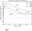
- Figure 4 shows the curves of the equation (1) compared to the model provided by Polach in the article "Creep forces in simulations of traction vehicles on adhesion limit" in WEAR 258, pages 992-1000, published in 2005 by Elsevier .
- the parameters according to equation (1) are more simply calculated, in particular in real time, compared to the more complex estimation according to Polach.
- the three parameters a, b and c are capable of describing all sorts of behaviors one might encounter on real trains.
- the filter 24 is implemented in block 20 of Figure 2 .
- the adaptive control with linear filtering is built upon the adherence curves according to equation (1) and their parametrization.
- block 20 is adapted to calculate and/or track the maximum adherence point ⁇ est .
- the torque calculated by the motor controller 7 is used to calculate the adherence coefficient ⁇ est , in particular with a proper filter. From this information, the output torque T contr , to be applied by the motor controller 7, is calculated.
- Figure 3 shows a second filter 26 adapted to determine the optimal slip ⁇ 0 based on the maximal adherence coefficient ⁇ est .
- a least square filter for curve fitting is used for that purpose. Using the speed of the vehicle and the optimal slip ⁇ 0 , the optimal wheel rotational speed ⁇ 0 is be calculated.
- the second filter 26 is implemented in the block 20 of Figure 2 .
- Figure 3 shows a control 28, for example a PI (proportional integral) control, for a reference tracking.
- the control 28 uses as input signal an error signal of the rotational wheel speed we.
- the error signal we is calculated based on the difference between the optimal rotational speed ⁇ 0 and the actual wheel speed ⁇ .
- other controls in particular closed loop controls, may be used, for example a PID control.
- control 28 is implemented in block 22 of figure 2 .
- the control 28 provides as an output signal the regulated Torque T reg .
- FIG 3 shows an optional feedforward control 30 for a feedforward action.
- the feedforward control 30 is used to provide a dynamical adjustment of the control torque T contr based on knowledge about the process in the form of a mathematical model. In an example it uses the optimal rotational speed reference ⁇ 0 and its derivative as an input (not shown in Figure 3 ).
- the output of the feedforward control is a feedforward torque T ff .
- the torque T comp provided by the first (linear) filter 24, the output torque T reg provided by the control 28, and optionally the feedforward torque T ff are added to calculate the control torque T contr .
- control torque T contr exhibits reduced oscillations with advantages in term of mechanical wear of components.
- the optimal set point for the rotational wheel speed ⁇ 0 is estimated.
- a torque control loop is closed.
- the optimal wheel speed ⁇ 0 and/or the maximal adherence coefficient ⁇ est is updated in real time. Therefore, always a precise reference wheel rotational speed is used and the torque controller 16 avoids torque oscillations.
- the relative slip or slide is limited within a few percent so that the mechanical stress of the transmission components, for example the wheelset torsional oscillations, and as a consequence the maintenance costs, is reduced, with wheel lifetime improvement.
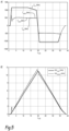
- Figure 5 shows schematically in graph A) a curve of the torques and in graph B) shows schematically a curve of the train's speed and the wheel speed.
- the control torque T contr, , the estimated torque T est and the real torque of the motor T motor are very close to each other or even nearly identical. Further, they do not show strong variations.
- graph B which shows the train speed vel train and the wheel speed vel wheel , the wheel speed vel wheel does not exhibit large variations.
- the invention permits the estimation of instantaneous value of wheel/rail friction coefficient and thus the estimation of the actual creep force exploitable by the railway vehicle in order to update accordingly the reference torque imposed by the controllers 7, 9, 16, in particular independently axle per axle.
- the maximal traction and/or braking force in all operating conditions, for example under different rail adherence characteristics.
- the torque estimated by the motor control 7 is used in order evaluate the optimal exploitable creep force and to update the torque T contr accordingly.
- the proposed torque control or ABC control device is able to estimate from the measurement the current rail conditions and provides a reference torque profile as close as possible to its optimal value. Further, according to the invention, when the optimal wheel speed is estimated, a torque control loop is closed and the resulting torque is less oscillating. Moreover, in traction the travelled distance is increased while in braking the stop distance is reduced.
Landscapes
- Engineering & Computer Science (AREA)
- Transportation (AREA)
- Mechanical Engineering (AREA)
- Power Engineering (AREA)
- Life Sciences & Earth Sciences (AREA)
- Sustainable Development (AREA)
- Sustainable Energy (AREA)
- Electric Propulsion And Braking For Vehicles (AREA)
Description
- The present invention concerns a method for controlling a railway vehicle comprising a motor controller for an electric machine acting on at least one wheel of the railway vehicle.
- Further, the present invention relates to a torque controller for a railway vehicle comprising a motor controller for an electric machine acting on at least one wheel of the railway vehicle.
- Finally, the present invention relates to a railway vehicle comprising such a controller and a computer program product.
-
WO 2017/175119 A1 relates to a method for calculating the speed of a railway vehicle and for controlling the torque. - Anti-slip/slide devices, according to state of art, perform an anti-blocking control (ABC) function usually maintaining effort at the limit of adherence by means of threshold of speed, acceleration and jerk. Typically, two strategies are used. The first strategy is aimed to cancel ("kill") the slide in order to operate as much as possible in the micro-slip range of the adherence curve. The first strategy requires quick torque modulation producing a periodical triangular torque reference profile. The second is aimed to "keep" the slide on a constant value in order to benefit of the cleaning effect due to wheel surface temperature increase (adherence regeneration). The second strategy, regulating the slide on a constant value, should apply a less variable effort but, adopting pre-defined thresholds of wheel slip/slide, acceleration and jerk, in real applications sometimes wheel effort and speed can exhibit undesired oscillations.
- The publication "Adaptive nonlinear control of braking in railway vehicles" of Caporale et. Al, 52nd IEEE conference on decision and control, December 10-13, 2013, Florence, Italy, discloses a technique for anti-slip control in railway vehicles. The paper discloses a simplified model to estimate an adherence curve.
- Object of the invention is to provide a reference torque as constant as possible in order to avoid the excitation of possible resonance of the transmissions and to follow the varying conditions of the rail.
- According to an aspect a method for controlling a railway vehicle comprising a motor controller for an electric machine according to
claim 1 is provided. - According to embodiments, the present invention may include one or more of the following features:
- the main controller receives an input by a driver of the railway vehicle and/or a train protection system;
- the electric machine is used for accelerating or decelerating the railway vehicle;
- the estimated torque is based on a voltage measured at an input of an inverter and/or phase currents of the electrical machine;
- the reference torque is calculated for each motorized axle separately, wherein a motorized axle is an axle on which the electrical machine acts;
- the electric machine is a permanent magnet electric machine or an asynchronous motor;
- the closed loop control uses a PI or PID control; and/or
- According to another aspect, a torque controller for a railway vehicle according to
claim 8 is provided. - According to a further aspect, a railway vehicle is provided comprising a motor controller for an electric machine acting on at least one wheel of the railway vehicle, a plurality of wheels, one or more wheel sensors for determining the rotational speed of the wheels, wherein the railway vehicle comprises a torque controller according to an embodiment disclosed herein.
- Finally, the present invention relates to a computer program product, comprising commands for implementing the method according to an embodiment disclosed herein when loaded and executed on a processor.
- So that the manner in which the above recited features of the present invention can be understood in detail, a more particular description of the invention, briefly summarized above, may be read by reference to embodiments. The accompanying drawings relate to embodiments of the invention and are described in the following:
-
Figure 1 shows schematically a railway vehicle; -
Figure 2 shows schematically a block diagram of a controller according to the invention; -
Figure 3 shows a schematic block diagram for determining a reference torque -
Figure 4 shows schematically adherence curves in dependence of the longitudinal slip; and -
Figure 5 shows schematically a curve of the torques; and a curve of the train's speed and the wheel speed. - According to an embodiment, the
electrical machine 5 is a permanent magnet machine. In another embodiment the electrical machine is an asynchronous motor. - The railway vehicle comprises further a
central controller 9, which is adapted to receive the commands of a driver or another system, which determines the reference speed and/or the reference torque for thewheels 3 Tref. In other words Tref, corresponds to the torque request. For example, the other system may be a train protection system, like the European Train Control System.
In an embodiment, therailway vehicle 1 includes at least onespeed sensor 12 for determining the speed v of therailway vehicle 1. Alternatively the speed v of therailway vehicle 1 can be estimated by an elaboration of the measured wheels speed performed by the ABC device. Further, therailway vehicle 1 has one ormore wheel sensors 14 for determining the rotational speed w of thewheels 3. In an embodiment, which may be combined with other embodiments disclosed herein, therailway vehicle 1 includes atorque controller 16. The torque controller is, according to an embodiment, an anti-blocking control (ABC) device. Thetorque controller 16 is adapted to calculate a reference torque, which is then provided to themotor controller 7. In an embodiment, thetorque controller 16 is connected to themotor controller 7 to receive a calculated motor torque. In addition, thetorque controller 16 is connected to themain controller 9 to receive the reference torque Tref. Further, thetorque controller 16 is directly or indirectly connected to thespeed sensor 12 and thewheel sensor 14 for receiving data for determining the actual speed of therailway vehicle 1 and the rotational speed of thewheels 3. In an embodiment, thetorque controller 16 is adapted to use the output of the one ormore wheel sensors 14 to estimate the speed v of therailway vehicle 1. - In an embodiment, the
central controller 9, themotor controller 7 and/or thetorque controller 16 are provided in a single controller or two or more controllers. - The
torque controller 16 is provided to prevent a sliding or slipping of thewheels 3. For example, thetorque controller 16 is adapted to calculate a maximal adherence between thewheels 3 and therail 2. -
Figure 2 shows in more detail the blocks provided in thetorque controller 16. Afirst block 20 is provided to estimate a maximal adherence (µest) of therailway vehicle 1, in particular thewheels 3, on the rail. Further, thefirst block 20 calculates the optimal wheel speed ω0, the slip σ and the absolute slip σAbsolute. Thefirst block 20 also provides the (actual) wheel speed w as an output. - As already described above, the adherence µ of a wheel on the rail depends on the wheel/rail surface conditions (e.g. dry or wet) and on the speed v of the railway vehicle. The slip or slide depends on the adherence µ, on the rotational speed w of the
wheels 3, on the speed v of therailway vehicle 1 and on the actual motoring or braking effort. In other words, the slip or slide is the difference between the tangential speed of the wheel (at the contact point on the rail) and the speed v of therailway vehicle 1. - Further, a
second block 22 is adapted to calculate the torque Tcontr to be provided by theelectrical machine 5 to thewheel 3. According to embodiments, thesecond block 22 implements the control as such. - The torque of the
wheel 3 depends on the torque of theelectrical machine 5. The output torque Tcontr of thesecond block 22 is adapted to be provided to themotor controller 7. Thesecond block 22 is adapted to control the torque based on the estimated maximal adherence µest of thefirst block 20, the slip σ and the reference torque Tref provided by thecentral controller 9. - In an embodiment, the
torque control 16, in particular thesecond block 22, includes a first selecting device to select whether the reference torque Tref is directly provided as output torque Tcontr or not. In a further example, thetorque control 16, in particular thesecond block 22, includes a second selecting device to discriminate between traction and braking operation. This information is given from the second block to thefirst block 20. For example, thesecond block 22 provides the values TSWITSCH and TBSWITCH to thefirst block 20. - TSWITCH is a logical (or boolean) value which is 0 (false) or 1 (true). When TSWITCH is 0 the reference control torque Tcontr given to the motor is the value Tref decided by the driver. When TSWITCH is 1 the torque control Tref is no longer given as output but the output Tcontr is calculated to exploit the maximum adherence force available. This signal is always less or equal (in absolute value) to the torque Tref desired by the driver. TBSWITCH is another logical value to discriminate between traction and braking operation.
- The
first block 20 and thus thetorque controller 16 are adapted to determine the optimal wheel speed ω0 and/or the maximal adherence µest based on the speed v of the railway vehicle, the wheel rotational speed w, and the estimated torque Test received from themotor controller 7. -
Figure 3 shows a block diagram of different components provided in thetorque controller 16. - In block 24 a linear filter is implemented to estimate the maximal adherence µest and to calculate a Torque Tcomp.
- For example, the linear filter uses the Test and the wheel rotational speed w for calculating the estimation of the maximal adherence µest. A Kalman filter is used for that purpose.
- The filter is adapted to calculate the adherence curve. For example, the adherence curve as described in the article " Adaptive nonlinear control of braking in railway vehicles" of Caporale et al. disclosed on the 52nd IEEE Conference on Decision and Control, December 10-13, 2013, Florence, Italy is used for that purpose.
- The adherence curve is calculated based on the following equation:

block 24. It is a function of the longitudinal slip σ and of three parameters a, b, and c.Figure 4 shows the curves of the equation (1) compared to the model provided by Polach in the article "Creep forces in simulations of traction vehicles on adhesion limit" in WEAR 258, pages 992-1000, published in 2005 by Elsevier. - The curves calculated according to Polach are solid, whereas the curves provided according to above equation are dashed. The curves are provided for several railway vehicle speeds, here a tramway speed. It should be noted that the leftmost part of the adherence curve, where the peak is located, is quite accurate while in the rightmost part at least the sign of the derivative of the fitted curve is coherent with the model.
- The parameters according to equation (1) are more simply calculated, in particular in real time, compared to the more complex estimation according to Polach. In other words, the three parameters a, b and c are capable of describing all sorts of behaviors one might encounter on real trains.
- According to an embodiment, the
filter 24 is implemented inblock 20 ofFigure 2 . - According to an embodiment, the adaptive control with linear filtering is built upon the adherence curves according to equation (1) and their parametrization. Thus it is possible that block 20 is adapted to calculate and/or track the maximum adherence point µest. In other words, the torque calculated by the
motor controller 7 is used to calculate the adherence coefficient µest, in particular with a proper filter. From this information, the output torque Tcontr, to be applied by themotor controller 7, is calculated. - Further,
Figure 3 shows asecond filter 26 adapted to determine the optimal slip σ0 based on the maximal adherence coefficient µest. A least square filter for curve fitting is used for that purpose. Using the speed of the vehicle and the optimal slip σ0, the optimal wheel rotational speed ω0 is be calculated. According to an embodiment, thesecond filter 26 is implemented in theblock 20 ofFigure 2 . -
Figure 3 shows acontrol 28, for example a PI (proportional integral) control, for a reference tracking. Thecontrol 28 uses as input signal an error signal of the rotational wheel speed we. The error signal we is calculated based on the difference between the optimal rotational speed ω0 and the actual wheel speed ω. In other embodiments also other controls, in particular closed loop controls, may be used, for example a PID control. - In an embodiment, which may be combined with other embodiments disclosed herein, the
control 28 is implemented inblock 22 offigure 2 . - The
control 28 provides as an output signal the regulated Torque Treg. - Finally,
Figure 3 shows anoptional feedforward control 30 for a feedforward action. Thefeedforward control 30 is used to provide a dynamical adjustment of the control torque Tcontr based on knowledge about the process in the form of a mathematical model. In an example it uses the optimal rotational speed reference ω0 and its derivative as an input (not shown inFigure 3 ). The output of the feedforward control is a feedforward torque Tff. - According to an embodiment, the torque Tcomp provided by the first (linear)
filter 24, the output torque Treg provided by thecontrol 28, and optionally the feedforward torque Tff are added to calculate the control torque Tcontr. - According to embodiments, the control torque Tcontr exhibits reduced oscillations with advantages in term of mechanical wear of components.
- Thus, according to the invention, the optimal set point for the rotational wheel speed ω0 is estimated. Using the optimal wheel rotational speed ω0, a torque control loop is closed.
- According to an embodiment, the optimal wheel speed ω0 and/or the maximal adherence coefficient µest is updated in real time. Therefore, always a precise reference wheel rotational speed is used and the
torque controller 16 avoids torque oscillations. Typically, the relative slip or slide is limited within a few percent so that the mechanical stress of the transmission components, for example the wheelset torsional oscillations, and as a consequence the maintenance costs, is reduced, with wheel lifetime improvement. -
Figure 5 shows schematically in graph A) a curve of the torques and in graph B) shows schematically a curve of the train's speed and the wheel speed. As it can be seen, the control torque Tcontr, , the estimated torque Test and the real torque of the motor Tmotor are very close to each other or even nearly identical. Further, they do not show strong variations. Moreover, as it can be seen from graph B), which shows the train speed veltrain and the wheel speed velwheel, the wheel speed velwheel does not exhibit large variations. - Thus, the invention permits the estimation of instantaneous value of wheel/rail friction coefficient and thus the estimation of the actual creep force exploitable by the railway vehicle in order to update accordingly the reference torque imposed by the
controllers - According to the invention, it is possible to provide the maximal traction and/or braking force, in all operating conditions, for example under different rail adherence characteristics. The torque estimated by the
motor control 7 is used in order evaluate the optimal exploitable creep force and to update the torque Tcontr accordingly. - According to the invention, the proposed torque control or ABC control device is able to estimate from the measurement the current rail conditions and provides a reference torque profile as close as possible to its optimal value. Further, according to the invention, when the optimal wheel speed is estimated, a torque control loop is closed and the resulting torque is less oscillating. Moreover, in traction the travelled distance is increased while in braking the stop distance is reduced.
Claims (10)
- Method for controlling a railway vehicle (1) comprising a motor controller (7) for an electric machine (5) acting on at least one wheel of the railway vehicle, and a torque controller (16), the method comprising:- receiving a torque request (Tref) from a central controller (9), the torque request is commanded by a driver;- determining the actual speed (v) of the railway vehicle (1);- determining the actual wheel rotational speed (ω) of the railway vehicle (1);- receiving an estimated torque (Test) from the motor controller (7);- estimating the maximal adherence coefficient (µest) based on the wheel rotational speed (ω), the actual speed (v) of the railway vehicle, and the estimated torque (Test) received from the motor controller, wherein a three parameters model is used in order to estimate the maximum adherence using the following equation:
 - determining an optimal slip based on the maximal adherence coefficient (µest) using a least square filter for curve fitting, and using the speed of the vehicle and the optimal slip to calculate the optimal wheel rotational speed (ω0);- calculating an error signal (ωe) based on the difference between the optimal wheel rotational speed (w0) and the actual wheel rotational speed (w);- calculating a regulated Torque (Treg) based on the calculated error signal using a closed loop control (28);- determining a reference torque (Tcontr) by adding the torque Tcomp provided by the linear filter (24), the output torque Treg provided by the closed loop control 28, to calculate the reference torque (Tcontr); and- selecting, by a first selecting device of the torque control, whether the torque request (Tref) is directly provided as an output torque (Tcontr) to the motor controller (7) or not, wherein when a logical value of a signal (TSWITCH) is 0, the torque request (Tref) commanded by the driver is given to the motor controller (7) as output torque (Tcontr), when the logical value of the signal (TSWITCH) is 1, the torque request (Tref) is no longer given as output torque (Tcontr), but the reference torque (Tcontr) calculated to exploit the maximum adherence force available is provided as output torque (Tcontr) to the motor controller.
 - Method according to claim 1, wherein the main controller (9) receives an input by a driver of the railway vehicle (1) and/or a train protection system.
- Method according to one of the preceding claims, wherein the electric machine is used for accelerating or decelerating the railway vehicle (1).
- Method according to one of the preceding claims, wherein the estimated torque (Test) is based on a voltage measured at an input of an inverter (8) and/or phase currents of the electrical machine (5).
- Method according to one of the preceding claims, wherein the reference torque (Tcontr) is calculated for each motorized axle separately.
- Method according to one of the preceding claims, wherein the electric machine (5) is a permanent magnet electric machine or an asynchronous motor (5).
- Method according to claim one of the preceding claims, wherein the closed loop control uses a PI or PID control.
- Torque controller (16) for a railway vehicle comprising a motor controller (7) for an electric machine (5) acting on at least one wheel of the railway vehicle, the torque controller being adapted to- receive torque request (Tref) from a central controller (9), the torque request is commanded by a driver;- receive or estimate the actual speed (v) of the railway vehicle (1);- receive the actual wheel rotational speed (w) of the railway vehicle (1);- receive an estimated torque (Test) from the motor controller (7);- estimate the maximum adherence coefficient (µest) based on the wheel rotational speed (ω), the actual speed (v) of the railway vehicle, and the estimated torque (Test) received from the motor controller, wherein a three parameters model is used in order to estimate the maximum adherence using the following equation:
 - determine an optimal slip based on the maximal adherence coefficient (µest) using a least square filter for curve fitting, and using the speed of the vehicle and the optimal slip to calculate the optimal wheel rotational speed (ω0);- calculate an error signal (we) based on the difference between the optimal wheel rotational speed (w0) and the actual wheel speed (w);- calculate a regulated Torque (Treg ) based on the calculated error signal using a closed loop control (28);- determine a reference torque (Tcontr) by adding the torque (Tcomp) provided by the linear filter (24), the output torque Treg provided by the closed loop control 28, to calculate the reference torque (Tcontr);;- select, by a first selecting device of the torque control (16), whether the torque request (Tref) is directly provided as an output torque (Tcontr) to the motor controller (7) or not, wherein when a logical value of a signal (TSWITCH) is 0, the torque request (Tref) commanded by the driver is given to the motor controller (7) as output torque (Tcontr), when the logical value of the signal (TSWITCH) is 1, the torque request (Tref) is no longer given as output torque (Tcontr), but the reference torque (Tcontr) calculated to exploit the maximum adherence force available is provided as output torque (Tcontr) to the motor controller.
 - Railway vehicle (1) comprising a motor controller (7) for an electric machine (5) acting on at least one wheel (3) of the railway vehicle (1), a plurality of wheels (3), one or more wheel sensors (14) for determining the rotational speed of the wheels (3) , wherein the railway vehicle comprises a torque controller according to claim 8.
- Computer program product, comprising commands for implementing the method according to one of the claims 1 to 7 when loaded and executed on a processor.
Priority Applications (3)
| Application Number | Priority Date | Filing Date | Title |
|---|---|---|---|
| EP19305032.5A EP3680123B1 (en) | 2019-01-09 | 2019-01-09 | Method for controlling a railway vehicle, a controller and a railway vehicle |
| RU2020100023A RU2804825C2 (en) | 2019-01-09 | 2020-01-09 | Method for controlling a railway vehicle, controller and railway vehicle |
| UAA202000154A UA128719C2 (en) | 2019-01-09 | 2020-01-09 | Method for controlling a railway vehicle, a controller and a railway vehicle |
Applications Claiming Priority (1)
| Application Number | Priority Date | Filing Date | Title |
|---|---|---|---|
| EP19305032.5A EP3680123B1 (en) | 2019-01-09 | 2019-01-09 | Method for controlling a railway vehicle, a controller and a railway vehicle |
Publications (2)
| Publication Number | Publication Date |
|---|---|
| EP3680123A1 EP3680123A1 (en) | 2020-07-15 |
| EP3680123B1 true EP3680123B1 (en) | 2024-11-20 |
Family
ID=65200751
Family Applications (1)
| Application Number | Title | Priority Date | Filing Date |
|---|---|---|---|
| EP19305032.5A Active EP3680123B1 (en) | 2019-01-09 | 2019-01-09 | Method for controlling a railway vehicle, a controller and a railway vehicle |
Country Status (2)
| Country | Link |
|---|---|
| EP (1) | EP3680123B1 (en) |
| UA (1) | UA128719C2 (en) |
Families Citing this family (6)
| Publication number | Priority date | Publication date | Assignee | Title |
|---|---|---|---|---|
| RU202349U1 (en) * | 2020-10-23 | 2021-02-12 | Андрей Сергеевич Космодамианский | DEVICE FOR INCREASING THE TRAINING OF THE DRIVING WHEELS OF THE LOCOMOTIVE WITH RAILS |
| EP4258540B1 (en) * | 2020-12-04 | 2026-03-04 | Hitachi, Ltd. | Drive device and drive method for rotary electric machine, and railway vehicle |
| CN113276689B (en) * | 2021-05-21 | 2022-05-10 | 江铃汽车股份有限公司 | Torque filtering method of pure electric vehicle |
| DE102021210463A1 (en) * | 2021-09-21 | 2023-03-23 | Siemens Mobility GmbH | Method and device for measuring a parameter relevant to the movement of a rail vehicle |
| WO2024075006A1 (en) * | 2022-10-05 | 2024-04-11 | Tesmec Rail S.R.L. | An integrated control for electric traction railway vehicles |
| CN119795934B (en) * | 2024-12-20 | 2025-10-24 | 西南交通大学 | Control method of permanent magnet synchronous traction system of train based on fixed time coordination theory |
Citations (2)
| Publication number | Priority date | Publication date | Assignee | Title |
|---|---|---|---|---|
| WO1995000355A1 (en) * | 1993-06-26 | 1995-01-05 | Abb Research Ltd | Process and device for slip control |
| KR100948350B1 (en) * | 2008-11-25 | 2010-03-22 | 한국철도기술연구원 | System for speed controlling of vehicle and its method |
Family Cites Families (2)
| Publication number | Priority date | Publication date | Assignee | Title |
|---|---|---|---|---|
| JP5562277B2 (en) * | 2011-03-07 | 2014-07-30 | Ntn株式会社 | Electric car |
| ITUA20162297A1 (en) * | 2016-04-05 | 2017-10-05 | Faiveley Transport Italia Spa | Procedure for calculating the speed of travel of a railway vehicle. |
-
2019
- 2019-01-09 EP EP19305032.5A patent/EP3680123B1/en active Active
-
2020
- 2020-01-09 UA UAA202000154A patent/UA128719C2/en unknown
Patent Citations (2)
| Publication number | Priority date | Publication date | Assignee | Title |
|---|---|---|---|---|
| WO1995000355A1 (en) * | 1993-06-26 | 1995-01-05 | Abb Research Ltd | Process and device for slip control |
| KR100948350B1 (en) * | 2008-11-25 | 2010-03-22 | 한국철도기술연구원 | System for speed controlling of vehicle and its method |
Non-Patent Citations (3)
| Title |
|---|
| "WEAR", vol. 258, 2005, ELSEVIER, article "Creep forces in simulations of traction vehicles on adhesion limit", pages: 992 - 1000 * |
| CAPORALE ET AL.: "Adaptive nonlinear control of braking in railway vehicles", 52ND IEEE CONFERENCE ON DECISION AND CONTROL, 10 December 2013 (2013-12-10) * |
| CAPORALE: "Adaptive nonlinear control of braking in railway vehicles", 52ND IEEE CONFERENCE ON DECISION AND CONTROL, 10 December 2013 (2013-12-10) * |
Also Published As
| Publication number | Publication date |
|---|---|
| EP3680123A1 (en) | 2020-07-15 |
| UA128719C2 (en) | 2024-10-09 |
| RU2020100023A (en) | 2021-07-13 |
Similar Documents
| Publication | Publication Date | Title |
|---|---|---|
| EP3680123A1 (en) | Method for controlling a railway vehicle, a controller and a railway vehicle | |
| EP3439928B1 (en) | Method for controlling and possibly recovering the adhesion of the wheels of a controlled axle of a railway vehicle | |
| EP3472008B1 (en) | A wheel controller for a vehicle | |
| Lin et al. | Self-learning fuzzy sliding-mode control for antilock braking systems | |
| JP4413931B2 (en) | Vehicle and vehicle control device | |
| US8055424B2 (en) | Real-time identification of maximum tire-road friction coefficient by induced wheels acceleration/deceleration | |
| CN101204953B (en) | Adaptive braking control method for a vehicle | |
| JP2008539112A (en) | Adaptive sliding protection for rail vehicles using slip regulators | |
| US6758087B2 (en) | Method, system and storage medium for determining a vehicle reference speed | |
| US20110015906A1 (en) | Method and device for determining a coefficient of friction | |
| EP3483029A1 (en) | System and method for testing adhesion conditions on a track | |
| EP1719676B1 (en) | System and method for tire/road friction estimation | |
| EP3194201B1 (en) | Wheel stability control based on the moment of an electrical motor | |
| JP2016111834A (en) | Braking/driving force control device of vehicle | |
| CN107380148A (en) | A kind of electric vehicle brake torque comprehensive regulation method and system | |
| Aligia et al. | EV traction control based on nonlinear observers considering longitudinal and lateral tire forces | |
| WO2016124629A1 (en) | Control system | |
| RU2758797C1 (en) | Method for protection against stalling of electric rolling stock with asynchronous tractive motors | |
| JP6064727B2 (en) | Control device for each wheel independent drive cart | |
| JP3906525B2 (en) | Vehicle speed setting device | |
| CN101565037B (en) | Turning track auxiliary system used for accelerating vehicle | |
| JP3697904B2 (en) | Inter-vehicle distance control device | |
| RU2804825C2 (en) | Method for controlling a railway vehicle, controller and railway vehicle | |
| JP3639170B2 (en) | Electric brake control method and apparatus | |
| de Bruijn et al. | On the performance increase of wheel deceleration control through force sensing |
Legal Events
| Date | Code | Title | Description |
|---|---|---|---|
| PUAI | Public reference made under article 153(3) epc to a published international application that has entered the european phase |
Free format text: ORIGINAL CODE: 0009012 |
|
| STAA | Information on the status of an ep patent application or granted ep patent |
Free format text: STATUS: THE APPLICATION HAS BEEN PUBLISHED |
|
| STAA | Information on the status of an ep patent application or granted ep patent |
Free format text: STATUS: REQUEST FOR EXAMINATION WAS MADE |
|
| AK | Designated contracting states |
Kind code of ref document: A1 Designated state(s): AL AT BE BG CH CY CZ DE DK EE ES FI FR GB GR HR HU IE IS IT LI LT LU LV MC MK MT NL NO PL PT RO RS SE SI SK SM TR |
|
| AX | Request for extension of the european patent |
Extension state: BA ME |
|
| 17P | Request for examination filed |
Effective date: 20200624 |
|
| RBV | Designated contracting states (corrected) |
Designated state(s): AL AT BE BG CH CY CZ DE DK EE ES FI FR GB GR HR HU IE IS IT LI LT LU LV MC MK MT NL NO PL PT RO RS SE SI SK SM TR |
|
| STAA | Information on the status of an ep patent application or granted ep patent |
Free format text: STATUS: EXAMINATION IS IN PROGRESS |
|
| 17Q | First examination report despatched |
Effective date: 20210623 |
|
| RAP1 | Party data changed (applicant data changed or rights of an application transferred) |
Owner name: POLITECNICO DI MILANO Owner name: ALSTOM HOLDINGS |
|
| P01 | Opt-out of the competence of the unified patent court (upc) registered |
Effective date: 20231027 |
|
| P04 | Withdrawal of opt-out of the competence of the unified patent court (upc) registered |
Effective date: 20231212 |
|
| GRAP | Despatch of communication of intention to grant a patent |
Free format text: ORIGINAL CODE: EPIDOSNIGR1 |
|
| STAA | Information on the status of an ep patent application or granted ep patent |
Free format text: STATUS: GRANT OF PATENT IS INTENDED |
|
| INTG | Intention to grant announced |
Effective date: 20240220 |
|
| P06 | Withdrawal of the competence of the unified patent court (upc) deleted | ||
| P03 | Opt-out of the competence of the unified patent court (upc) deleted | ||
| GRAJ | Information related to disapproval of communication of intention to grant by the applicant or resumption of examination proceedings by the epo deleted |
Free format text: ORIGINAL CODE: EPIDOSDIGR1 |
|
| STAA | Information on the status of an ep patent application or granted ep patent |
Free format text: STATUS: EXAMINATION IS IN PROGRESS |
|
| GRAP | Despatch of communication of intention to grant a patent |
Free format text: ORIGINAL CODE: EPIDOSNIGR1 |
|
| STAA | Information on the status of an ep patent application or granted ep patent |
Free format text: STATUS: GRANT OF PATENT IS INTENDED |
|
| INTC | Intention to grant announced (deleted) | ||
| INTG | Intention to grant announced |
Effective date: 20240708 |
|
| GRAS | Grant fee paid |
Free format text: ORIGINAL CODE: EPIDOSNIGR3 |
|
| GRAA | (expected) grant |
Free format text: ORIGINAL CODE: 0009210 |
|
| STAA | Information on the status of an ep patent application or granted ep patent |
Free format text: STATUS: THE PATENT HAS BEEN GRANTED |
|
| AK | Designated contracting states |
Kind code of ref document: B1 Designated state(s): AL AT BE BG CH CY CZ DE DK EE ES FI FR GB GR HR HU IE IS IT LI LT LU LV MC MK MT NL NO PL PT RO RS SE SI SK SM TR |
|
| REG | Reference to a national code |
Ref country code: GB Ref legal event code: FG4D |
|
| REG | Reference to a national code |
Ref country code: CH Ref legal event code: EP |
|
| REG | Reference to a national code |
Ref country code: DE Ref legal event code: R096 Ref document number: 602019062172 Country of ref document: DE |
|
| REG | Reference to a national code |
Ref country code: IE Ref legal event code: FG4D |
|
| REG | Reference to a national code |
Ref country code: SE Ref legal event code: TRGR |
|
| REG | Reference to a national code |
Ref country code: LT Ref legal event code: MG9D |
|
| REG | Reference to a national code |
Ref country code: NL Ref legal event code: MP Effective date: 20241120 |
|
| PG25 | Lapsed in a contracting state [announced via postgrant information from national office to epo] |
Ref country code: IS Free format text: LAPSE BECAUSE OF FAILURE TO SUBMIT A TRANSLATION OF THE DESCRIPTION OR TO PAY THE FEE WITHIN THE PRESCRIBED TIME-LIMIT Effective date: 20250320 Ref country code: HR Free format text: LAPSE BECAUSE OF FAILURE TO SUBMIT A TRANSLATION OF THE DESCRIPTION OR TO PAY THE FEE WITHIN THE PRESCRIBED TIME-LIMIT Effective date: 20241120 Ref country code: PT Free format text: LAPSE BECAUSE OF FAILURE TO SUBMIT A TRANSLATION OF THE DESCRIPTION OR TO PAY THE FEE WITHIN THE PRESCRIBED TIME-LIMIT Effective date: 20250320 |
|
| PG25 | Lapsed in a contracting state [announced via postgrant information from national office to epo] |
Ref country code: FI Free format text: LAPSE BECAUSE OF FAILURE TO SUBMIT A TRANSLATION OF THE DESCRIPTION OR TO PAY THE FEE WITHIN THE PRESCRIBED TIME-LIMIT Effective date: 20241120 Ref country code: NL Free format text: LAPSE BECAUSE OF FAILURE TO SUBMIT A TRANSLATION OF THE DESCRIPTION OR TO PAY THE FEE WITHIN THE PRESCRIBED TIME-LIMIT Effective date: 20241120 |
|
| REG | Reference to a national code |
Ref country code: AT Ref legal event code: MK05 Ref document number: 1743291 Country of ref document: AT Kind code of ref document: T Effective date: 20241120 |
|
| PG25 | Lapsed in a contracting state [announced via postgrant information from national office to epo] |
Ref country code: BG Free format text: LAPSE BECAUSE OF FAILURE TO SUBMIT A TRANSLATION OF THE DESCRIPTION OR TO PAY THE FEE WITHIN THE PRESCRIBED TIME-LIMIT Effective date: 20241120 |
|
| PG25 | Lapsed in a contracting state [announced via postgrant information from national office to epo] |
Ref country code: ES Free format text: LAPSE BECAUSE OF FAILURE TO SUBMIT A TRANSLATION OF THE DESCRIPTION OR TO PAY THE FEE WITHIN THE PRESCRIBED TIME-LIMIT Effective date: 20241120 |
|
| PG25 | Lapsed in a contracting state [announced via postgrant information from national office to epo] |
Ref country code: NO Free format text: LAPSE BECAUSE OF FAILURE TO SUBMIT A TRANSLATION OF THE DESCRIPTION OR TO PAY THE FEE WITHIN THE PRESCRIBED TIME-LIMIT Effective date: 20250220 |
|
| PG25 | Lapsed in a contracting state [announced via postgrant information from national office to epo] |
Ref country code: AT Free format text: LAPSE BECAUSE OF FAILURE TO SUBMIT A TRANSLATION OF THE DESCRIPTION OR TO PAY THE FEE WITHIN THE PRESCRIBED TIME-LIMIT Effective date: 20241120 Ref country code: LV Free format text: LAPSE BECAUSE OF FAILURE TO SUBMIT A TRANSLATION OF THE DESCRIPTION OR TO PAY THE FEE WITHIN THE PRESCRIBED TIME-LIMIT Effective date: 20241120 Ref country code: GR Free format text: LAPSE BECAUSE OF FAILURE TO SUBMIT A TRANSLATION OF THE DESCRIPTION OR TO PAY THE FEE WITHIN THE PRESCRIBED TIME-LIMIT Effective date: 20250221 |
|
| PG25 | Lapsed in a contracting state [announced via postgrant information from national office to epo] |
Ref country code: PL Free format text: LAPSE BECAUSE OF FAILURE TO SUBMIT A TRANSLATION OF THE DESCRIPTION OR TO PAY THE FEE WITHIN THE PRESCRIBED TIME-LIMIT Effective date: 20241120 |
|
| PG25 | Lapsed in a contracting state [announced via postgrant information from national office to epo] |
Ref country code: RS Free format text: LAPSE BECAUSE OF FAILURE TO SUBMIT A TRANSLATION OF THE DESCRIPTION OR TO PAY THE FEE WITHIN THE PRESCRIBED TIME-LIMIT Effective date: 20250220 |
|
| PG25 | Lapsed in a contracting state [announced via postgrant information from national office to epo] |
Ref country code: SM Free format text: LAPSE BECAUSE OF FAILURE TO SUBMIT A TRANSLATION OF THE DESCRIPTION OR TO PAY THE FEE WITHIN THE PRESCRIBED TIME-LIMIT Effective date: 20241120 |
|
| PG25 | Lapsed in a contracting state [announced via postgrant information from national office to epo] |
Ref country code: DK Free format text: LAPSE BECAUSE OF FAILURE TO SUBMIT A TRANSLATION OF THE DESCRIPTION OR TO PAY THE FEE WITHIN THE PRESCRIBED TIME-LIMIT Effective date: 20241120 |
|
| PG25 | Lapsed in a contracting state [announced via postgrant information from national office to epo] |
Ref country code: EE Free format text: LAPSE BECAUSE OF FAILURE TO SUBMIT A TRANSLATION OF THE DESCRIPTION OR TO PAY THE FEE WITHIN THE PRESCRIBED TIME-LIMIT Effective date: 20241120 |
|
| PG25 | Lapsed in a contracting state [announced via postgrant information from national office to epo] |
Ref country code: RO Free format text: LAPSE BECAUSE OF FAILURE TO SUBMIT A TRANSLATION OF THE DESCRIPTION OR TO PAY THE FEE WITHIN THE PRESCRIBED TIME-LIMIT Effective date: 20241120 |
|
| PG25 | Lapsed in a contracting state [announced via postgrant information from national office to epo] |
Ref country code: SK Free format text: LAPSE BECAUSE OF FAILURE TO SUBMIT A TRANSLATION OF THE DESCRIPTION OR TO PAY THE FEE WITHIN THE PRESCRIBED TIME-LIMIT Effective date: 20241120 |
|
| PG25 | Lapsed in a contracting state [announced via postgrant information from national office to epo] |
Ref country code: CZ Free format text: LAPSE BECAUSE OF FAILURE TO SUBMIT A TRANSLATION OF THE DESCRIPTION OR TO PAY THE FEE WITHIN THE PRESCRIBED TIME-LIMIT Effective date: 20241120 |
|
| REG | Reference to a national code |
Ref country code: DE Ref legal event code: R097 Ref document number: 602019062172 Country of ref document: DE |
|
| PG25 | Lapsed in a contracting state [announced via postgrant information from national office to epo] |
Ref country code: MC Free format text: LAPSE BECAUSE OF FAILURE TO SUBMIT A TRANSLATION OF THE DESCRIPTION OR TO PAY THE FEE WITHIN THE PRESCRIBED TIME-LIMIT Effective date: 20241120 Ref country code: LU Free format text: LAPSE BECAUSE OF NON-PAYMENT OF DUE FEES Effective date: 20250109 |
|
| PLBE | No opposition filed within time limit |
Free format text: ORIGINAL CODE: 0009261 |
|
| STAA | Information on the status of an ep patent application or granted ep patent |
Free format text: STATUS: NO OPPOSITION FILED WITHIN TIME LIMIT |
|
| PG25 | Lapsed in a contracting state [announced via postgrant information from national office to epo] |
Ref country code: BE Free format text: LAPSE BECAUSE OF NON-PAYMENT OF DUE FEES Effective date: 20250131 |
|
| PG25 | Lapsed in a contracting state [announced via postgrant information from national office to epo] |
Ref country code: FR Free format text: LAPSE BECAUSE OF NON-PAYMENT OF DUE FEES Effective date: 20250120 |
|
| 26N | No opposition filed |
Effective date: 20250821 |
|
| REG | Reference to a national code |
Ref country code: BE Ref legal event code: MM Effective date: 20250131 |
|
| GBPC | Gb: european patent ceased through non-payment of renewal fee |
Effective date: 20250220 |
|
| REG | Reference to a national code |
Ref country code: CH Ref legal event code: R18 Free format text: ST27 STATUS EVENT CODE: U-0-0-R10-R18 (AS PROVIDED BY THE NATIONAL OFFICE) Effective date: 20260106 |
|
| PG25 | Lapsed in a contracting state [announced via postgrant information from national office to epo] |
Ref country code: GB Free format text: LAPSE BECAUSE OF NON-PAYMENT OF DUE FEES Effective date: 20250220 |
|
| PG25 | Lapsed in a contracting state [announced via postgrant information from national office to epo] |
Ref country code: IE Free format text: LAPSE BECAUSE OF NON-PAYMENT OF DUE FEES Effective date: 20250109 |
|
| REG | Reference to a national code |
Ref country code: CH Ref legal event code: U11 Free format text: ST27 STATUS EVENT CODE: U-0-0-U10-U11 (AS PROVIDED BY THE NATIONAL OFFICE) Effective date: 20260201 |
|
| PGFP | Annual fee paid to national office [announced via postgrant information from national office to epo] |
Ref country code: SE Payment date: 20260127 Year of fee payment: 8 |
|
| PGFP | Annual fee paid to national office [announced via postgrant information from national office to epo] |
Ref country code: DE Payment date: 20260114 Year of fee payment: 8 |
|
| PGFP | Annual fee paid to national office [announced via postgrant information from national office to epo] |
Ref country code: IT Payment date: 20260107 Year of fee payment: 8 |
|
| PGFP | Annual fee paid to national office [announced via postgrant information from national office to epo] |
Ref country code: CH Payment date: 20260201 Year of fee payment: 8 |