EP3680092A1 - Preform shaping device - Google Patents
Preform shaping device Download PDFInfo
- Publication number
- EP3680092A1 EP3680092A1 EP18853766.6A EP18853766A EP3680092A1 EP 3680092 A1 EP3680092 A1 EP 3680092A1 EP 18853766 A EP18853766 A EP 18853766A EP 3680092 A1 EP3680092 A1 EP 3680092A1
- Authority
- EP
- European Patent Office
- Prior art keywords
- preform
- corrugated
- mold
- shaping
- bags
- Prior art date
- Legal status (The legal status is an assumption and is not a legal conclusion. Google has not performed a legal analysis and makes no representation as to the accuracy of the status listed.)
- Pending
Links
- 238000007493 shaping process Methods 0.000 title claims abstract description 136
- 239000000463 material Substances 0.000 claims abstract description 195
- 238000000034 method Methods 0.000 claims abstract description 90
- 238000003825 pressing Methods 0.000 claims abstract description 21
- 239000000835 fiber Substances 0.000 claims description 75
- 239000002131 composite material Substances 0.000 claims description 66
- 239000011347 resin Substances 0.000 claims description 47
- 229920005989 resin Polymers 0.000 claims description 47
- 230000003014 reinforcing effect Effects 0.000 claims description 26
- 239000011230 binding agent Substances 0.000 claims description 20
- 229920001187 thermosetting polymer Polymers 0.000 claims description 19
- 238000000465 moulding Methods 0.000 claims description 16
- 229920001169 thermoplastic Polymers 0.000 claims description 15
- 239000004416 thermosoftening plastic Substances 0.000 claims description 15
- 238000010438 heat treatment Methods 0.000 claims description 12
- 238000007789 sealing Methods 0.000 claims description 4
- 238000002844 melting Methods 0.000 claims 1
- 230000008018 melting Effects 0.000 claims 1
- 238000010030 laminating Methods 0.000 description 14
- 238000001723 curing Methods 0.000 description 11
- 229920001343 polytetrafluoroethylene Polymers 0.000 description 9
- 239000004810 polytetrafluoroethylene Substances 0.000 description 9
- 239000004744 fabric Substances 0.000 description 5
- -1 polytetrafluoroethylene Polymers 0.000 description 5
- 230000008878 coupling Effects 0.000 description 4
- 238000010168 coupling process Methods 0.000 description 4
- 238000005859 coupling reaction Methods 0.000 description 4
- 239000000565 sealant Substances 0.000 description 4
- 238000007796 conventional method Methods 0.000 description 3
- 238000002347 injection Methods 0.000 description 3
- 239000007924 injection Substances 0.000 description 3
- 238000001029 thermal curing Methods 0.000 description 3
- 239000004698 Polyethylene Substances 0.000 description 2
- 239000004918 carbon fiber reinforced polymer Substances 0.000 description 2
- 230000000694 effects Effects 0.000 description 2
- 239000011152 fibreglass Substances 0.000 description 2
- 239000012466 permeate Substances 0.000 description 2
- 229920000573 polyethylene Polymers 0.000 description 2
- 238000001721 transfer moulding Methods 0.000 description 2
- 230000037303 wrinkles Effects 0.000 description 2
- 229920001634 Copolyester Polymers 0.000 description 1
- 239000004593 Epoxy Substances 0.000 description 1
- 239000004952 Polyamide Substances 0.000 description 1
- 239000004743 Polypropylene Substances 0.000 description 1
- 239000000853 adhesive Substances 0.000 description 1
- 230000001070 adhesive effect Effects 0.000 description 1
- 238000001816 cooling Methods 0.000 description 1
- 230000000881 depressing effect Effects 0.000 description 1
- 238000012423 maintenance Methods 0.000 description 1
- 239000000155 melt Substances 0.000 description 1
- 239000002184 metal Substances 0.000 description 1
- 239000000203 mixture Substances 0.000 description 1
- 238000012986 modification Methods 0.000 description 1
- 230000004048 modification Effects 0.000 description 1
- 229920002647 polyamide Polymers 0.000 description 1
- 229920000728 polyester Polymers 0.000 description 1
- 229920000139 polyethylene terephthalate Polymers 0.000 description 1
- 239000005020 polyethylene terephthalate Substances 0.000 description 1
- 229920000098 polyolefin Polymers 0.000 description 1
- 229920001155 polypropylene Polymers 0.000 description 1
- 230000000630 rising effect Effects 0.000 description 1
- 239000005060 rubber Substances 0.000 description 1
- 238000006467 substitution reaction Methods 0.000 description 1
- 238000009941 weaving Methods 0.000 description 1
Images


Classifications
-
- B—PERFORMING OPERATIONS; TRANSPORTING
- B30—PRESSES
- B30B—PRESSES IN GENERAL
- B30B5/00—Presses characterised by the use of pressing means other than those mentioned in the preceding groups
- B30B5/02—Presses characterised by the use of pressing means other than those mentioned in the preceding groups wherein the pressing means is in the form of a flexible element, e.g. diaphragm, urged by fluid pressure
-
- B—PERFORMING OPERATIONS; TRANSPORTING
- B29—WORKING OF PLASTICS; WORKING OF SUBSTANCES IN A PLASTIC STATE IN GENERAL
- B29B—PREPARATION OR PRETREATMENT OF THE MATERIAL TO BE SHAPED; MAKING GRANULES OR PREFORMS; RECOVERY OF PLASTICS OR OTHER CONSTITUENTS OF WASTE MATERIAL CONTAINING PLASTICS
- B29B11/00—Making preforms
- B29B11/06—Making preforms by moulding the material
- B29B11/12—Compression moulding
-
- B—PERFORMING OPERATIONS; TRANSPORTING
- B29—WORKING OF PLASTICS; WORKING OF SUBSTANCES IN A PLASTIC STATE IN GENERAL
- B29B—PREPARATION OR PRETREATMENT OF THE MATERIAL TO BE SHAPED; MAKING GRANULES OR PREFORMS; RECOVERY OF PLASTICS OR OTHER CONSTITUENTS OF WASTE MATERIAL CONTAINING PLASTICS
- B29B11/00—Making preforms
- B29B11/14—Making preforms characterised by structure or composition
- B29B11/16—Making preforms characterised by structure or composition comprising fillers or reinforcement
-
- B—PERFORMING OPERATIONS; TRANSPORTING
- B29—WORKING OF PLASTICS; WORKING OF SUBSTANCES IN A PLASTIC STATE IN GENERAL
- B29C—SHAPING OR JOINING OF PLASTICS; SHAPING OF MATERIAL IN A PLASTIC STATE, NOT OTHERWISE PROVIDED FOR; AFTER-TREATMENT OF THE SHAPED PRODUCTS, e.g. REPAIRING
- B29C43/00—Compression moulding, i.e. applying external pressure to flow the moulding material; Apparatus therefor
- B29C43/02—Compression moulding, i.e. applying external pressure to flow the moulding material; Apparatus therefor of articles of definite length, i.e. discrete articles
- B29C43/10—Isostatic pressing, i.e. using non-rigid pressure-exerting members against rigid parts or dies
- B29C43/12—Isostatic pressing, i.e. using non-rigid pressure-exerting members against rigid parts or dies using bags surrounding the moulding material or using membranes contacting the moulding material
-
- B—PERFORMING OPERATIONS; TRANSPORTING
- B29—WORKING OF PLASTICS; WORKING OF SUBSTANCES IN A PLASTIC STATE IN GENERAL
- B29C—SHAPING OR JOINING OF PLASTICS; SHAPING OF MATERIAL IN A PLASTIC STATE, NOT OTHERWISE PROVIDED FOR; AFTER-TREATMENT OF THE SHAPED PRODUCTS, e.g. REPAIRING
- B29C43/00—Compression moulding, i.e. applying external pressure to flow the moulding material; Apparatus therefor
- B29C43/32—Component parts, details or accessories; Auxiliary operations
- B29C43/36—Moulds for making articles of definite length, i.e. discrete articles
- B29C43/3642—Bags, bleeder sheets or cauls for isostatic pressing
-
- B—PERFORMING OPERATIONS; TRANSPORTING
- B29—WORKING OF PLASTICS; WORKING OF SUBSTANCES IN A PLASTIC STATE IN GENERAL
- B29C—SHAPING OR JOINING OF PLASTICS; SHAPING OF MATERIAL IN A PLASTIC STATE, NOT OTHERWISE PROVIDED FOR; AFTER-TREATMENT OF THE SHAPED PRODUCTS, e.g. REPAIRING
- B29C43/00—Compression moulding, i.e. applying external pressure to flow the moulding material; Apparatus therefor
- B29C43/32—Component parts, details or accessories; Auxiliary operations
- B29C43/56—Compression moulding under special conditions, e.g. vacuum
-
- B—PERFORMING OPERATIONS; TRANSPORTING
- B29—WORKING OF PLASTICS; WORKING OF SUBSTANCES IN A PLASTIC STATE IN GENERAL
- B29C—SHAPING OR JOINING OF PLASTICS; SHAPING OF MATERIAL IN A PLASTIC STATE, NOT OTHERWISE PROVIDED FOR; AFTER-TREATMENT OF THE SHAPED PRODUCTS, e.g. REPAIRING
- B29C70/00—Shaping composites, i.e. plastics material comprising reinforcements, fillers or preformed parts, e.g. inserts
- B29C70/04—Shaping composites, i.e. plastics material comprising reinforcements, fillers or preformed parts, e.g. inserts comprising reinforcements only, e.g. self-reinforcing plastics
- B29C70/28—Shaping operations therefor
- B29C70/40—Shaping or impregnating by compression not applied
- B29C70/42—Shaping or impregnating by compression not applied for producing articles of definite length, i.e. discrete articles
- B29C70/44—Shaping or impregnating by compression not applied for producing articles of definite length, i.e. discrete articles using isostatic pressure, e.g. pressure difference-moulding, vacuum bag-moulding, autoclave-moulding or expanding rubber-moulding
-
- B—PERFORMING OPERATIONS; TRANSPORTING
- B29—WORKING OF PLASTICS; WORKING OF SUBSTANCES IN A PLASTIC STATE IN GENERAL
- B29C—SHAPING OR JOINING OF PLASTICS; SHAPING OF MATERIAL IN A PLASTIC STATE, NOT OTHERWISE PROVIDED FOR; AFTER-TREATMENT OF THE SHAPED PRODUCTS, e.g. REPAIRING
- B29C70/00—Shaping composites, i.e. plastics material comprising reinforcements, fillers or preformed parts, e.g. inserts
- B29C70/04—Shaping composites, i.e. plastics material comprising reinforcements, fillers or preformed parts, e.g. inserts comprising reinforcements only, e.g. self-reinforcing plastics
- B29C70/28—Shaping operations therefor
- B29C70/40—Shaping or impregnating by compression not applied
- B29C70/42—Shaping or impregnating by compression not applied for producing articles of definite length, i.e. discrete articles
- B29C70/46—Shaping or impregnating by compression not applied for producing articles of definite length, i.e. discrete articles using matched moulds, e.g. for deforming sheet moulding compounds [SMC] or prepregs
- B29C70/461—Rigid movable compressing mould parts acting independently from opening or closing action of the main mould
-
- B—PERFORMING OPERATIONS; TRANSPORTING
- B29—WORKING OF PLASTICS; WORKING OF SUBSTANCES IN A PLASTIC STATE IN GENERAL
- B29C—SHAPING OR JOINING OF PLASTICS; SHAPING OF MATERIAL IN A PLASTIC STATE, NOT OTHERWISE PROVIDED FOR; AFTER-TREATMENT OF THE SHAPED PRODUCTS, e.g. REPAIRING
- B29C70/00—Shaping composites, i.e. plastics material comprising reinforcements, fillers or preformed parts, e.g. inserts
- B29C70/04—Shaping composites, i.e. plastics material comprising reinforcements, fillers or preformed parts, e.g. inserts comprising reinforcements only, e.g. self-reinforcing plastics
- B29C70/28—Shaping operations therefor
- B29C70/40—Shaping or impregnating by compression not applied
- B29C70/42—Shaping or impregnating by compression not applied for producing articles of definite length, i.e. discrete articles
- B29C70/46—Shaping or impregnating by compression not applied for producing articles of definite length, i.e. discrete articles using matched moulds, e.g. for deforming sheet moulding compounds [SMC] or prepregs
- B29C70/48—Shaping or impregnating by compression not applied for producing articles of definite length, i.e. discrete articles using matched moulds, e.g. for deforming sheet moulding compounds [SMC] or prepregs and impregnating the reinforcements in the closed mould, e.g. resin transfer moulding [RTM], e.g. by vacuum
-
- B—PERFORMING OPERATIONS; TRANSPORTING
- B29—WORKING OF PLASTICS; WORKING OF SUBSTANCES IN A PLASTIC STATE IN GENERAL
- B29C—SHAPING OR JOINING OF PLASTICS; SHAPING OF MATERIAL IN A PLASTIC STATE, NOT OTHERWISE PROVIDED FOR; AFTER-TREATMENT OF THE SHAPED PRODUCTS, e.g. REPAIRING
- B29C70/00—Shaping composites, i.e. plastics material comprising reinforcements, fillers or preformed parts, e.g. inserts
- B29C70/04—Shaping composites, i.e. plastics material comprising reinforcements, fillers or preformed parts, e.g. inserts comprising reinforcements only, e.g. self-reinforcing plastics
- B29C70/28—Shaping operations therefor
- B29C70/54—Component parts, details or accessories; Auxiliary operations, e.g. feeding or storage of prepregs or SMC after impregnation or during ageing
- B29C70/549—Details of caul plates, e.g. materials or shape
-
- B—PERFORMING OPERATIONS; TRANSPORTING
- B29—WORKING OF PLASTICS; WORKING OF SUBSTANCES IN A PLASTIC STATE IN GENERAL
- B29D—PRODUCING PARTICULAR ARTICLES FROM PLASTICS OR FROM SUBSTANCES IN A PLASTIC STATE
- B29D99/00—Subject matter not provided for in other groups of this subclass
- B29D99/001—Producing wall or panel-like structures, e.g. for hulls, fuselages, or buildings
- B29D99/0014—Producing wall or panel-like structures, e.g. for hulls, fuselages, or buildings provided with ridges or ribs, e.g. joined ribs
-
- B—PERFORMING OPERATIONS; TRANSPORTING
- B30—PRESSES
- B30B—PRESSES IN GENERAL
- B30B1/00—Presses, using a press ram, characterised by the features of the drive therefor, pressure being transmitted directly, or through simple thrust or tension members only, to the press ram or platen
- B30B1/003—Presses, using a press ram, characterised by the features of the drive therefor, pressure being transmitted directly, or through simple thrust or tension members only, to the press ram or platen by an elastic bag or diaphragm expanded by fluid pressure
-
- B—PERFORMING OPERATIONS; TRANSPORTING
- B29—WORKING OF PLASTICS; WORKING OF SUBSTANCES IN A PLASTIC STATE IN GENERAL
- B29C—SHAPING OR JOINING OF PLASTICS; SHAPING OF MATERIAL IN A PLASTIC STATE, NOT OTHERWISE PROVIDED FOR; AFTER-TREATMENT OF THE SHAPED PRODUCTS, e.g. REPAIRING
- B29C43/00—Compression moulding, i.e. applying external pressure to flow the moulding material; Apparatus therefor
- B29C43/32—Component parts, details or accessories; Auxiliary operations
- B29C43/36—Moulds for making articles of definite length, i.e. discrete articles
- B29C43/3642—Bags, bleeder sheets or cauls for isostatic pressing
- B29C2043/3649—Inflatable bladders using gas or fluid and related details
-
- B—PERFORMING OPERATIONS; TRANSPORTING
- B29—WORKING OF PLASTICS; WORKING OF SUBSTANCES IN A PLASTIC STATE IN GENERAL
- B29C—SHAPING OR JOINING OF PLASTICS; SHAPING OF MATERIAL IN A PLASTIC STATE, NOT OTHERWISE PROVIDED FOR; AFTER-TREATMENT OF THE SHAPED PRODUCTS, e.g. REPAIRING
- B29C43/00—Compression moulding, i.e. applying external pressure to flow the moulding material; Apparatus therefor
- B29C43/32—Component parts, details or accessories; Auxiliary operations
- B29C43/56—Compression moulding under special conditions, e.g. vacuum
- B29C2043/561—Compression moulding under special conditions, e.g. vacuum under vacuum conditions
-
- B—PERFORMING OPERATIONS; TRANSPORTING
- B29—WORKING OF PLASTICS; WORKING OF SUBSTANCES IN A PLASTIC STATE IN GENERAL
- B29K—INDEXING SCHEME ASSOCIATED WITH SUBCLASSES B29B, B29C OR B29D, RELATING TO MOULDING MATERIALS OR TO MATERIALS FOR MOULDS, REINFORCEMENTS, FILLERS OR PREFORMED PARTS, e.g. INSERTS
- B29K2105/00—Condition, form or state of moulded material or of the material to be shaped
- B29K2105/06—Condition, form or state of moulded material or of the material to be shaped containing reinforcements, fillers or inserts
- B29K2105/08—Condition, form or state of moulded material or of the material to be shaped containing reinforcements, fillers or inserts of continuous length, e.g. cords, rovings, mats, fabrics, strands or yarns
- B29K2105/0872—Prepregs
Definitions
- Embodiments described herein relate generally to a preform shaping apparatus, a method of shaping a preform and a method of producing a composite material structure.
- a typical wing structural object of an aircraft has a structure in which reinforcing structural members, such as spars, ribs and stringers, have been disposed between an upper panel (skin) and a lower panel.
- a structural member having a corrugated cross section is known as one of structural members which reinforce a wing structural object (for example, refer to Japanese Patent Application Publication JP HI 1-99 993 A ).
- GFRP glass fiber reinforced plastics
- CFRP carbon fiber reinforced plastics
- Typical methods of molding composite material include a method for laminating prepregs, which are fiber sheets impregnated with uncured thermosetting resin, and subsequently thermally curing the laminated prepregs with an autoclave apparatus or an oven, and an RTM (resin transfer molding) method for impregnating fiber sheets with thermosetting resin after laminating the fiber sheets, and subsequently thermally curing the thermosetting resin.
- VaRTM vacuum assisted resin transfer molding
- a hybrid method which uses the RTM method together with a method for laminating prepregs, and subsequently, thermally curing the laminated prepregs is also known as a method of molding composite material.
- a laminated body of prepregs shaped according to a shape of a composite material, a laminated body of fibers which has not been impregnated with resin in an RTM method and a laminated body of fibers which has been impregnated with resin in an RTM method are each called a preform in the technical field of molding composite material.
- a laminated body of fibers which has not been impregnated with resin is called a dry preform.
- Methods of shaping a corrugated preform include a method for laminating prepreg sheets on a shaping mold having corrugated concavity and convexity (for example, refer to Japanese Patent Application Publication JP HI 1-99 993 A ).
- the shaping mold can also be used as a mold for thermal forming. That is, a corrugated composite material can be molded by thermally curing a laminated body of prepregs laminated on a shaping mold by an autoclave apparatus or an oven.
- an RTM method can also be adopted (for example, refer to Japanese Patent Application Publication JP HI 1-99 993 A ).
- a laminated body of fibers shaped into a corrugated shape in advance is placed between an upper mold and a lower mold each produced according to corrugated concavity and convexity.
- thermosetting resin is injected and thermally cured.
- a corrugated composite material can be molded. In this case, it is necessary to produce a dry preform shaped into a corrugated shape.
- Methods of shaping a dry preform prior to molding a composite material include a method for laminating fibers on a shaping mold, and subsequently, heating the laminated fibers with a heater or the like (for example, refer to Japanese Patent Application Publication JP 2006-123 404 A ). Moreover, a shaping method by heating fibers pressed on a shaping mold with bagging by vacuuming is also known (for example, refer to Japanese Patent Application Publication JP 2010-126 573 A ).
- the fibers are stretched, and thereby may not fit to concavity portions of the shaping mold.
- a cavity is generated in each corner of the concavity portions of the shaping mold, and thereby it becomes difficult to produce a preform having an intended shape.
- an object of the present invention is to make it possible to produce a preform and a composite material having a complicated shape with satisfactory quality.
- a preform shaping apparatus includes a rigid mold and a pressurizing jig.
- the rigid mold has a shape corresponding to a shape of a preform which has been shaped.
- the pressurizing jig presses an unshaped material of the preform to the rigid mold at different positions and different timing.
- a method of shaping a preform includes: producing the shaped preform by pressing an unshaped material of the preform to a rigid mold at different positions and different timing; and using a pressurizing jig for pressing the material.
- the rigid mold has a shape corresponding to a shape of the preform.
- the pressurizing jig is adapted to apply pressures on the material at the different positions and the different timing.
- a method of producing a composite material includes: placing core jigs on a laminated body of prepregs for a panel and placing the corrugated dry preform, produced by the above-mentioned method, on the placed core jigs; impregnating the corrugated dry preform with uncured thermosetting resin by injecting the uncured thermosetting resin into an area sealed by a vacuum bag in a state where the corrugated dry preform placed on the core jigs has been bagged with the vacuum bag; and producing the composite material structure having the panel and a corrugated reinforcing member attached to the panel, by thermally curing the laminated body of the prepregs for the panel and the thermosetting resin with which the corrugated dry preform has been impregnated.
- the laminated body of the prepregs for the panel is placed on a lower rigid mold.
- the core jigs correspond to a shape of the corrugated dry preform.
- a method of producing a composite material structure includes: molding a corrugated composite material; producing a panel made of another composite material; and producing the composite material structure having the panel and a corrugated reinforcing member attached to the panel, by assembling the corrugated composite material to the panel.
- the corrugated dry preform or the corrugated laminated body of the prepregs, produced by the above-mentioned method, is used as a material of the corrugated composite material.
- FIG. 1 is a view for explaining a preform shaping method using a preform shaping apparatus according to the first embodiment of the present invention
- FIG. 2 is a top view of the preform shaping apparatus shown by (A) in FIG. 1 .
- a preform shaping apparatus 1 produces a preform, having an intended shape, by shaping a material M.
- a preform to be produced may be a dry preform, consisting of fiber sheets which have not been impregnated with uncured thermosetting resin, or a thermally uncured composite material, consisting of fiber sheets which have been impregnated with uncured thermosetting resin.
- the material M is a laminated body of sheet-like fibers.
- a shaped dry preform is used as a material for molding a composite material under an RTM method. Specifically, a composite material is molded by impregnating a dry preform with uncured thermosetting resin and thermally curing the thermosetting resin with an autoclave apparatus or an oven. Therefore, a dry preform shaped with the preform shaping apparatus 1 may be continuously impregnated with resin and thermally cured. In other words, the preform shaping apparatus 1 may also be used as a molding apparatus of a composite material.
- the preform when a preform made of fibers impregnated with resin is to be shaped by the preform shaping apparatus 1, the preform can be produced by either impregnating a shaped dry preform with resin, or shaping a laminated body of prepregs. Therefore, when a preform in a state that fibers have been impregnated with resin is to be shaped by the preform shaping apparatus 1, the material M is a laminated body of sheet-like fibers or a laminated body of sheet-like prepregs.
- FIG. 1 shows an example of a case of producing a dry preform having a corrugated cross section by shaping fibers which have been laminated in a sheet shape. Accordingly, a case where a corrugated dry preform is shaped by the preform shaping apparatus 1 will be explained as an example with reference to FIG. 1 hereinafter.
- a corrugated dry preform is used as a material of a corrugated reinforcing member, such as a corrugated stringer, a corrugated rib or a corrugated spar, made of a composite material.
- a corrugated reinforcing member is used as a part of a wing structure of an aircraft. Specifically, a corrugated reinforcing member is mainly attached to an upper panel or a lower panel as a member for reinforcing the panel.
- the preform shaping apparatus 1 can be composed of a lower mold 2, inner vacuum bags 3 and an outer vacuum bag 4 as shown by (A) of FIG. 1 .
- the inner vacuum bags 3 are disposed at concave portions of the lower mold 2 respectively, and the unshaped material M is placed on the lower mold 2 and the inner vacuum bags 3. Then, the material M is covered with the outer vacuum bag 4.
- the lower mold 2 is a rigid mold which has a shape corresponding to a shaped preform. Therefore, when a corrugated dry preform is shaped, the lower mold 2 has corrugated concavity and convexity on the surface as shown in FIG. 1 . Specifically, in order to shape projecting portions of a corrugated dry preform, convex portions 2A, each having an elongated structure, are formed on the surface of the lower mold 2. The length of each convex portion 2A formed on the surface of the lower mold 2 may be adjusted with the width of a dry preform, or may be made longer than the width of a dry preform.
- Each inner vacuum bag 3 has flexibility and a closed bag structure, and is disposed between the lower mold 2 and the material M. Specifically, the inner vacuum bags 3 each having a closed structure are respectively placed between the convex portions 2A of the lower mold 2 for shaping projecting portions of a corrugated dry preform. Therefore, each inner vacuum bag 3 has a hollow tubular structure of which both ends have been closed.
- the material M consisting of an unshaped flat sheet-like fiber bundles can be placed on the lower mold 2 where the inflated inner vacuum bags 3 have been placed at corresponding concave portions respectively.
- a tube 3A for vacuuming is coupled to at least one end part of each inner vacuum bag 3.
- a hole for vacuuming may be formed on each concave portion formed between the two adjacent convex portions 2A of the lower mold 2 while a suction port is formed on each inner vacuum bag 3 so that the suction ports formed on the inner vacuum bags 3 may be coupled to the holes for vacuuming formed on the lower mold 2 respectively.
- the outer vacuum bag 4 is a bagging film for sealing at least the atmosphere side of the material M in order to bag the material M. Therefore, a tube 4A for vacuuming is also coupled to the outer vacuum bag 4.
- the material M is sealed by the outer vacuum bag 4 from outside in a state where the inner vacuum bags 3 have been disposed on the lower mold 2. In other words, the material M is disposed between the outer vacuum bag 4 and a set of the inner vacuum bags 3 and the convex portions 2A of the lower mold 2.
- the whole lower mold 2 on which the inner vacuum bags 3 and the material M have been placed can be covered by the outer vacuum bag 4, and the edge of the outer vacuum bag 4 can be stuck on the flat portion of the lower mold 2 by a sealant 5, as shown in FIG. 2 .
- the end parts of each convex portion 2A may be exposed outside the outer vacuum bag 4. In that case, the edge of the outer vacuum bag 4 is stuck on the convex portions 2A of the lower mold 2 by the sealant 5.
- each inner vacuum bag 3 The end part of the tube 3A attached to each inner vacuum bag 3 is led to the outside of the outer vacuum bag 4 in order to be coupled to the vacuum device 6. Therefore, it is suitable to stick a clearance gap between each tube 3A and the lower mold 2 as well as a clearance gap between each tube 3A and the outer vacuum bag 4 by the sealant 5 from a viewpoint of keeping satisfactory airtightness in an area covered by the outer vacuum bag 4.
- the tube 4A for evacuating air from a space inside the outer vacuum bag 4 may be formed on the lower mold 2 instead of coupling to the outer vacuum bag 4.
- Vacuuming of the area sealed by the outer vacuum bag 4 and vacuuming of the inside of each inner vacuum bag 3 are performed at different timing. Specifically, the vacuuming of the inside of each inner vacuum bag 3 is performed at an appropriate timing after the vacuuming of the area sealed by the outer vacuum bag 4.
- the vacuuming of the area sealed by the outer vacuum bag 4 and the vacuuming of the inside of each inner vacuum bag 3 can be performed using the common vacuum device 6 by coupling a pipe 7 as exemplified in FIG. 1 and FIG. 2 .
- the respective tubes 3A of the inner vacuum bags 3 and the tube 4A of the outer vacuum bag 4 can be coupled to the common pipe 7 through cocks 8 respectively.
- an operator can determine timing of vacuuming by opening and closing each cock 8 manually.
- each cock 8 may be composed of an electric, hydraulic or pneumatic cock automatically opening and closing, and opening and closing of each cock 8 may be automatically controlled with a controlling device.
- control signals for instructing timing of vacuuming can be generated in an electric circuit, a hydraulic circuit, or a pneumatic signal circuit composing the controlling device, and the generated control signals can be output to the cocks 8 respectively.
- timing of vacuuming in the inner vacuum bags 3 and the outer vacuum bag 4 to which the cocks 8 have been coupled respectively can be automatically controlled.
- independent vacuum devices may be coupled to the tubes 3A of the inner vacuum bags 3 and the tube 4A of the outer vacuum bag 4 respectively.
- an operator can determine timing for vacuuming by determining timing for switching the power supplies of the vacuum devices on respectively.
- the timing for driving each vacuum device may be automatically controlled by a controlling device which integrally controls operation of the respective vacuum devices.
- the order of vacuuming in the inner vacuum bags 3 performed after vacuuming in the outer vacuum bag 4 is determined as an order by which a space is not generated between the material M and the lower mold 2 even when the material M is pressed on the lower mold 2.
- portions, in which spaces are most likely to be generated, between the material M and the lower mold 2 are concave round chamfered portions at both side corners of each concave portion formed between the adjacent convex portions 2A.
- FIG. 3 is a view for explaining a problem in the conventional method of shaping a dry preform.
- unshaped fiber sheets 11 can be placed on a conventional corrugated lower mold 10 which has convex portions 10A each having an elongated structure, and then the unshaped fiber sheets 11 can be covered with a bagging film 12.
- the vacuum device 13 When the area covered with the bagging film 12 is evacuated by the vacuum device 13, the atmospheric pressure is applied in the thickness direction of the fiber sheets 11.
- the preform shaping apparatus 1 evacuates the insides of the inner vacuum bags 3 in an appropriate order so that spaces may not be generated between the material M and the concave round chamfered portions of the lower mold 2.
- What is necessary in order to prevent spaces from being generated between the material M and the concave round chamfered portions of the lower mold 2 is to determine such an order of evacuating the insides of the inner vacuum bags 3 that the material M may be firstly pressed only to a desired concave portion selected out of the concave portions of the lower bold 10, and subsequently the material M may be pressed to adjacent one or two concave portions after the material M has contacted to the selected concave portion.
- only the central concave portion of the lower mold 2 can be firstly selected as a target to which the material M is brought into contact.
- only the inner vacuum bag 3 placed in the central concave portion of the lower mold 2 can be evacuated.
- each pressure inside the other inner vacuum bags 3 can be made an approximate atmospheric pressure by opening the other inner vacuum bags 3 to the atmospheric air beforehand.
- two concave portions in both sides adjacent to the central concave portion of the lower mold 2 can be selected as targets to which the material M are brought into contact.
- only the two inner vacuum bags 3 placed in the two concave portions in both sides adjacent to the central concave portion of the lower mold 2 can be evacuated. Thereby, the material M can be slid and fitted to the two concave portions in both sides adjacent to the central concave portion of the lower mold 2.
- the two concave portions adjacent in the further outsides can be selected as targets to which the material M are brought into contact. Then, the material M can be fitted to the two selected concave portions by evacuating only the two corresponding inner vacuum bags 3 .
- FIG. 1 shows an example where the material M is sequentially fit to the concave portions of the lower mold 2 from the central concave portion toward outside concave portions
- fitting of the material M may be started from another concave portion.
- the material M may be sequentially fitted to the concave portions from the concave portion in one end side toward the concave portion in the other end side.
- it may be omitted to place the inner vacuum bag 3 in the concave portion to which the material M should be firstly fit.
- the material M can be fitted to the first concave portion by evacuating the inside of the outer vacuum bag 4.
- the material M When the material M is sequentially fitted to the concave portions of the lower mold 2 from the center toward the outsides, the material M can be simultaneously pressed to two concave portions after pressing the material M to the central concave portion. Therefore, time required for shaping a preform can be shortened.
- the material M when the material M is sequentially fitted to the concave portions of the lower mold 2 from one end side toward the other end side, a direction of sliding the material M can be made one direction after pressing the material M to the first concave portion in one end side. Therefore, such a trouble that the end part of the material M lacks the length of a preform, or conversely that an excess surplus remains can be avoided.
- the material M when a corrugated dry preform of which both end parts are concave is shaped as exemplified in FIG. 1 , the material M can be shaped so that one edge of the material M may be coincided with one edge of a dry preform, and subsequently the material M can be slid in one direction and sequentially fitted to the other concave portions.
- each of the tubes 3A attached to the inner vacuum bags 3 are desirable to be flatly crushed by evacuating the insides of the inner vacuum bags 3 respectively in the area sealed by the outer vacuum bag 4. Therefore, it is appropriate to make each of the tubes 3A attached to the inner vacuum bags 3 of a material having flexibility as well as the inner vacuum bags 3.
- each inner vacuum bag 3 may be made different from the length of a concave portion of the lower mold 2 without coinciding with the length of the concave portion of the lower mold 2, as exemplified in FIG. 2 .
- the length of each inner vacuum bag 3 is made long so that the inner vacuum bag 3 protrudes to the outside of the area sealed by the outer vacuum bag 4, air inflow into the outer vacuum bag 4 after evacuation can be prevented by sealing a clearance gap between the outer vacuum bag 4 and each inner vacuum bag 3, and a clearance gap between each inner vacuum bag 3 and the lower mold 2.
- each inner vacuum bag 3 may be made shorter than the length of the convex portion 2A of the lower mold 2.
- the edge portion of the material M is stretched between the adjacent convex portions 2A immediately after evacuating the insides of the outer vacuum bags 4, and thereby spaces may be generated between the material M and the lower mold 2.
- the edge portion of the material M deforms following deformations of the central portions of the material M. Therefore, not only the central portions of the material M but the edge portion can be brought into contact to the concave portions of the lower mold 2.
- the material M is pressed on the rigid lower mold 2, which has a form corresponding to a form of a shaped preform, at different timing and positions utilizing the atmospheric pressure. Therefore, it can be said that a pressurizing jig 9, which presses the material M before shaping a preform at different positions and timing, is formed by the inner vacuum bags 3 and the outer vacuum bag 4.
- the outer vacuum bag 4 composing the pressurizing jig 9 undertakes a role of applying a differential pressure between a pressure in the area sealed by the outer vacuum bag 4 and the atmospheric pressure, on the material M at different positions.
- the inner vacuum bags 3 composing the pressurizing jig 9 are placed between the lower mold 2 and the material M, and undertake a role of pressing the material M on the lower mold 2 at different positions and timing by changing the timing of vacuuming.
- the inner vacuum bags 3 are placed at positions corresponding to the different positions for pressing the material M, i.e., the back side of the positions where the sheet like material M is pressed using the atmospheric pressure.
- a shaped preform can be produced by pressing the material M at different positions and timing using the pressurizing jig 9 composed of the inner vacuum bags 3 and the outer vacuum bag 4.
- a preform to be produced may be not only a dry preform but also a preform consisting of fibers which have been impregnated with resin.
- a preform consisting of fibers which have been impregnated with resin can be produced by injecting uncured resin into the outer vacuum bag 4 with maintenance of vacuuming of the insides of the outer vacuum bag 4 and the inner vacuum bags 3 after shaping a dry preform. In that case, an injection port for injecting resin is formed in the outer vacuum bag 4 or the lower mold 2.
- a preform consisting of fibers which have been impregnated with resin can be produced by shaping the material M consisting of a laminated body of prepreg sheets instead of fiber sheets. That is, a corrugated laminated body of prepregs can be shaped as a preform.
- a shape of a preform may be not only a corrugated shape but also a shape having a plurality of concave portions.
- a shape of a preform may be not only a corrugated shape but also a shape having a plurality of concave portions.
- the lower mold 2 has at least two concave portions in which the inner vacuum bags 3 can be placed, an effect of preventing spaces between the material M and the lower mold 2 due to stretching the material M from being generated can be achieved by changing timing for evacuating the insides of the inner vacuum bags 3. Therefore, a dry preform or a laminated body of prepregs having concave portions can be shaped with the preform shaping apparatus 1.
- a sheet 20 for sliding the material M to the convex portions 2A of the lower mold 2 and the inner vacuum bags 3 may be placed at least between the material M, and the lower mold 2 and the inner vacuum bags 3.
- the material M is a laminated body of prepregs
- the material of the sheet 20 for smoothly sliding the material M may be polytetrafluoroethylene (PTFE), paper, polyethylene or the like.
- PTFE polytetrafluoroethylene
- thermoplastic binder When thermoplastic binder is placed among fiber layers, a dry preform is shaped by heating the binder with an oven or the like so that the binder may be melted. That is, a laminated body of fiber sheets including thermoplastic binder is shaped in high temperature environment in an oven. Then, when the laminated body of fiber sheets is cooled down to a normal temperature, the melted thermoplastic binder is cured again inside the shaped laminated body of fiber sheets, and thereby a shape of the dry preform can be kept.
- fiber sheets including Z-threads for bearing strength in a thickness direction of a dry preform may also be used as the material M of the dry preform.
- Z-threads are fibers which bear strength in a thickness direction of fiber sheets, and fibers including Z-threads can be produced by weaving fibers spatially.
- a fabric of which fibers have been woven spatially is also called a three dimensional fabric.
- Practical examples include a three dimensional fabric where some fibers are disposed in a corrugated shape whose amplitude direction is a thickness direction of the fiber sheets.
- the dry preform can be shaped without using and heating thermoplastic binder. This is because a three dimensional fabric including Z threads has a function to keep a deformed shape.
- FIG. 4 is a view for explaining a method of integrally molding a composite material structure composed of a panel and a corrugated reinforcing member attached to the panel, using a dry preform produced with the preform shaping apparatus 1 shown in FIG. 1 .
- a corrugated dry preform is produced using the preform shaping apparatus 1.
- the inflated inner vacuum bags 3 are placed between the convex portions 2A of the lower mold 2 respectively.
- the inner vacuum bags 3 are disposed between the lower mold 2 and the material M, at the opposite side of positions where the material M is pressed to the concave portions of the lower mold 2 using the atmospheric pressure respectively.
- the laminated body of the fiber sheets used as the material M can be produced by laminating the fiber sheets on the convex portions 2A of the lower mold 2 and the inner vacuum bags 3 with an automatic laminating device or manually by an operator, for example.
- the laminated body of the fiber sheets may be produced by laminating the fiber sheets on another rigid jig of which surface is flat.
- a commercially available laminated body of fiber sheets may be placed on the convex portions 2A of the lower mold 2 and the inner vacuum bags 3.
- thermoplastic binder between plies of the fiber sheets.
- a laminated body of fibers including Z-threads may also be used as the material M.
- the use of the binder can be omitted.
- the material M is sealed by the outer vacuum bag 4 from the outside in a state where the inner vacuum bags 3 have been placed.
- the outer vacuum bag 4 is stuck on the lower mold 2 by the sealant 5.
- the tube 4A of the outer vacuum bag 4 is coupled to the pipe 7 for vacuuming. Meanwhile, the power supply of the vacuum device 6 is turned on, and thereby the vacuum device 6 drives.
- the cock 8 attached to the tube 4A of the outer vacuum bag 4 is opened.
- the respective tubes 3A of the inner vacuum bags 3 are not coupled to the pipe 7, and the respective inner vacuum bags 3 are opened to the atmospheric air. Therefore, air is discharged only from a space among the respective inner vacuum bags 3 and the outer vacuum bag 4.
- the closed area sealed by the outer vacuum bag 4 becomes a vacuum state. Therefore, the respective inner vacuum bags 3 remains the inflated state, and the material M is supported on the inflated inner vacuum bags 3 and the convex portions 2A of the lower mold 2, in an approximately flat state, as shown by (A) of FIG. 1 .
- step S2 the tubes 3A of the inner vacuum bags 3 are coupled to the pipe 7 for vacuuming, and the atmospheric temperature is increased with a heating device. Then, the cocks 8 attached to the tubes 3A of the inner vacuum bags 3 are sequentially opened at different timing.
- the inner vacuum bags 3 sequentially deflate, and the material M is pushed against the lower mold 2 at the different positions and timing using the atmospheric pressure. At this time, the material M slides and moves between the outer vacuum bag 4, and the convex portions 2A of the lower mold 2 and the inner vacuum bags 3 before vacuuming.
- the material M can be smoothly slid by shielding both sides of the material M by the sheets 20 made of PTFE or the like.
- the material M contacts to the corrugated lower mold 2 without clearances as shown by (D) of FIG. 1 .
- the material M is fibers including Z-threads and inserting thermoplastic binder is omitted, shaping of a dry preform 30 is completed by pressing the material M to the lower mold 2 using the atmospheric pressure. That is, the dry preform 30 which has been shaped into a corrugated shape can be obtained.
- thermoplastic binder when thermoplastic binder is included in the material M, the material M is made to contact to the corrugated lower mold 2 under a heating environment with an oven or the like. As a result, the thermoplastic binder melts inside the material M which has deformed into the corrugated shape. After that, when the temperature of the material M is returned to the normal temperature by air cooling or the like, the thermoplastic binder is cured again inside the material M which has deformed into the corrugated shape. Thereby, shaping of the dry preform 30 is completed. That is, the dry preform 30 which has been shaped into the corrugated shape can be obtained.
- step S3 prepregs 32 for an upper panel or a lower panel are laminated on a rigid lower mold 31 for molding a composite material. Thereby, a laminated body of the prepregs 32 for the panel is produced.
- step S4 core jigs 33 formed according to the shape of the corrugated dry preform 30 are placed on the laminated body of the prepregs 32 for the panel, which has been laminated on the lower mold 31. As necessary, jigs for positioning the core jigs 33 are used for placing the core jigs 33.
- step S5 the corrugated dry preform 30 produced by the preform shaping apparatus 1 is set on the laminated body of the prepregs 32 for the panel and the core jigs 33.
- the corrugated dry preform 30 is previously removed from the preform shaping apparatus 1.
- step S6 the dry preform 30 which has been set on the laminated body of the prepregs 32 for the panel and the core jigs 33 is bagged with a vacuum bag 34. That is, the area sealed by the vacuum bag 34 is evacuated by a vacuum device 35. Then, uncured thermosetting resin 36 is injected into the area sealed by the vacuum bag 34.
- the thermosetting resin 36 can be injected from a resin injection port formed in the vacuum bag 34 or the lower mold 31.
- the vacuum bag 34 may be sealed with the core jigs 33 and the lower mold 31 so that end portions of the core jigs 33 protrude outside the vacuum bag 34, and the thermosetting resin 36 may be injected from a resin injection port, formed in at least one of the core jigs 33, to the area sealed by the vacuum bag 34.
- the corrugated dry preform 30 is impregnated with the uncured thermosetting resin 36.
- thermosetting resin 36 with which the laminated body of the prepregs 32 for the panel and the corrugated laminated body of fibers have been impregnated is thermally cured by a heating device 37, such as an oven or an autoclave apparatus.
- a composite material structure 40 having a panel 38 and a corrugated reinforcing member 39 attached to the panel 38 can be produced.
- the composite material structure 40 having the panel 38 and the corrugated reinforcing member 39 attached to the panel 38 can be used as a part of a fuselage or a wing structure composing a main wing, a horizontal tail, a vertical tail or a center wing.
- FIG. 4 shows a method for integrally molding the composite material structure 40, having a structure in which the corrugated reinforcing member 39 has been attached to the panel 38, by a hybrid method by which the corrugated reinforcing member 39 is produced by a VaRTM method while the panel 38 is produced by laminating and thermally curing prepregs
- the composite material structure 40 having the panel 38 and the corrugated reinforcing member 39 attached to the panel 38 may also be produced by another molding method with the preform shaping apparatus 1.
- FIG. 5 is a view for explaining a method of producing a composite material structure 40A, composed of the panel 38 and the corrugated reinforcing member 39 attached to the panel 38, by assembling the panel 38 produced separately from the corrugated reinforcing member 39 produced by the preform shaping apparatus 1 shown in FIG. 1 .
- a corrugated laminated body of prepregs is produced using the preform shaping apparatus 1.
- the inflated inner vacuum bags 3 are placed between the convex portions 2A of the lower mold 2 respectively.
- a laminated body of prepreg sheets of which both sides are desirably shielded by the sheets 20, such as PTFE, is placed, as the material M, on the inner vacuum bags 3 and the convex portions 2A of the lower mold 2.
- the inner vacuum bags 3 are disposed between the lower mold 2 and the material M, at the opposite side of positions where the material M is pressed to the concave portions of the lower mold 2 using the atmospheric pressure respectively.
- the laminated body of the prepregs laminated approximately flatly and used as the material M can be produced by laminating the prepreg sheets on the convex portions 2A of the lower mold 2 and the inner vacuum bags 3 with an automatic laminating device or manually by an operator, for example.
- the laminated body of the prepreg may be produced by laminating the prepreg sheets on another rigid jig of which surface is flat.
- the material M is bagged by the outer vacuum bag 4 while the insides of the inner vacuum bags 3 are kept at an approximately atmospheric pressure, similarly to the operation in step S1 of FIG. 4 .
- the material M is kept in an approximately flat state on the inflated inner vacuum bags 3 and the convex portions 2A of the lower mold 2 as shown by (A) of FIG. 1 .
- step S21 the atmospheric temperature is increased by an oven or the like, and the insides of the inner vacuum bags 3 are evacuated sequentially, similarly to the operation in step S2 of FIG. 4 .
- the material M consisting of the laminated body of the prepregs can be contacted to the corrugated lower mold 2 without generating clearances, as shown by (D) of FIG. 1 .
- a laminated body 41 of the prepregs which has been shaped into a corrugated shape can be produced. That is, a corrugated preform made of the fibers impregnated with the resin can be obtained.
- step S22 the laminated body 41 of the prepregs which has been shaped into the corrugated shape is thermally cured.
- the laminated body 41 of the prepregs bagged by the outer vacuum bag 4 is thermally cured by a heating device 37A, such as an oven or an autoclave apparatus.
- a heating device 37A such as an oven or an autoclave apparatus.
- the corrugated reinforcing member 39 can be molded from the material consisting of the corrugated laminated body 41 of the prepregs.
- the panel 38 made of a composite material is produced by a desired molding method.
- the panel 38 made of the composite material can be produced by laminating prepregs for the panel on the lower mold 31 as shown in step S3 of FIG. 4 , and subsequent thermal curing of the laminated prepregs with a heating device 37B, such as an oven or an autoclave apparatus.
- step S24 the corrugated reinforcing member 39 is assembled with the panel 38 made of the composite material.
- the panel 38 made of the composite material can be placed on an assembly jig 42, and the corrugated reinforcing member 39 can be attached to the panel 38 using adhesive or fasteners.
- the composite material structure 40A having the structure in which the corrugated reinforcing member 39 has been attached to the panel 38 can be produced.
- a corrugated preform consisting of fibers impregnated with resin may be produced by a VaRTM method using a laminated body of fiber sheets as the material M.
- the corrugated reinforcing member 39 can be molded by thermal curing of the preform, bagged with the outer vacuum bag 4, by an oven, an autoclave apparatus or the like.
- the corrugated dry preform 30 produced by the preform shaping apparatus 1 in the example shown in FIG. 4 may not be removed from the preform shaping apparatus 1, and continuously the corrugated reinforcing member 39 can be molded by a VaRTM method.
- the preform shaping apparatus 1 can be used not only as an apparatus for shaping a preform but also as a composite material molding apparatus carried into an oven, an autoclave apparatus or the like to be used for thermal curing of a composite material.
- the preform shaping apparatus 1, the method of shaping a preform and the method of producing a composite material structure can bring the material M into contact to the concave portions of the lower mold 2 certainly by bagging the inner vacuum bags 3 together with the material M with the outer vacuum bag 4, and evacuating the insides of the inner vacuum bags 3 sequentially at different timing.
- the method of shaping a preform and the method of producing a composite material structure, a preform and a composite material having a complicated shape which could not be produced with satisfactory quality by a conventional method, can be produced by a simple apparatus at low cost. That is, only the lower mold 2 can be needed as a shaping mold having concavity and convexity, by utilizing the atmospheric pressure. In other words, it is not necessary to produce an upper mold which has a complicated shape.
- laying the sheets 20 made of PTFE or the like makes it possible to smoothly slide the material M relative to the lower mold 2, the inner vacuum bags 3, and the outer vacuum bag 4 while preventing disorder of fibers.
- FIG. 6 is a view for explaining a preform shaping method using a preform shaping apparatus according to the second embodiment of the present invention.
- a method of shaping a preform using a preform shaping apparatus 1A in the second embodiment shown in FIG. 6 is different from the method of shaping a preform using the preform shaping apparatus 1 in the first embodiment in a point that rigid plates 50 having shapes corresponding to the shapes of the concave portions of the lower mold 2 respectively are placed between the outer vacuum bag 4 and the material M. Since other structures and actions in the second embodiment are not substantially different from those in the first embodiment, explanation for the same or corresponding elements is omitted with attaching the same signs.
- the rigid plates 50 which have shapes corresponding to the shapes of the concave portions of the lower mold 2 can be placed between the outer vacuum bag 4 and the material M.
- the material M is sandwiched between the inner vacuum bags 3 and the plates 50 as shown by (A) of FIG. 6 .
- Each plate 50 can be made of a metal or a composite material which has necessary strength, for example. Moreover, each plate 50 is made of a material which has the heat resistance to heating when thermoplastic binder is heated to be melted at the time of shaping a preform and when a composite material is thermally cured using the preform shaping apparatus 1A.
- Each plate 50 has a shape whose width is equivalent to the distance between the adjacent convex portions 2A.
- the length of each plate 50 can be made equivalent to the length of the inner vacuum bag 3 or the length of the convex portion 2A, for example.
- the rigid plates 50 can be fitted to the concave portions respectively after the inner vacuum bags 3 have been deflated, as shown by (B), (C) and (D) of FIG. 6 .
- the material M can be pressed to the round chamfered portions formed at the corners of the concave portions of the lower mold 2 more certainly, as shown by (D) of FIG. 6 , in a case where a dry preform or a laminated body of prepregs, having a plurality of concave portions, like a corrugated dry preform or a corrugated laminated body of prepregs is shaped.
- FIG. 7 is a view for explaining a preform shaping method using a preform shaping apparatus according to the third embodiment of the present invention.
- a method of shaping a preform using a preform shaping apparatus 1B in the third embodiment shown in FIG. 7 is different from the method of shaping a preform using the preform shaping apparatus 1 in the first embodiment in a point that a plurality of the inner vacuum bags 3 are placed in at least one of the concave portions of the lower mold 2. Since other structures and actions in the third embodiment are not substantially different from those in the first embodiment, explanation for the same or corresponding elements is omitted with attaching the same signs.
- two or more inner vacuum bags 3 may be placed between the adjacent two convex portions 2A of the lower mold 2.
- the inner vacuum bags 3 between the adjacent two convex portions 2A can be sequentially evacuated at different timing.
- the inner vacuum bag 3 disposed at the center in the center concave portion can be evacuated and deflated as shown by (B-1) of FIG. 7
- the two inner vacuum bags 3 disposed at both sides can be evacuated and deflated as shown by (B-2) of FIG. 7 .
- the inner vacuum bags 3 can be evacuated and deflated sequentially from the inner vacuum bags 3 closest to the central concave portion as shown by (C-1), (C-2) and (C-3) of FIG. 7 .
- the inner vacuum bags 3 disposed in the two concave portions in both end sides of the lower mold 2 where the convex portion 2A stands in only one side can be evacuated and deflated as shown by (D) of FIG. 7 .
- the material M can be gradually pressed to each concave portion formed between the adjacent convex portions 2A. Therefore, the distance by which the material M slides can be made not more than a constant distance, which can prevent disorder and wrinkle from being generated more certainly. Moreover, it is possible to prevent the material M from being pulled and stretched toward both sides between the adjacent convex portions 2A, and thereby the material M can be pressed to the round chamfered portions formed at the corners of the concave portions of the lower mold 2 more certainly.
- FIG. 8 is a view for explaining a preform shaping method using a preform shaping apparatus according to the fourth embodiment of the present invention.
- a method of shaping a preform using a preform shaping apparatus 1C in the fourth embodiment shown in FIG. 8 is different from the method of shaping a preform using the preform shaping apparatus 1 in the first embodiment in a point that a curved panel-shaped preform is shaped. Since other structures and actions in the fourth embodiment are not substantially different from those in the first embodiment, explanation for the same or corresponding elements is omitted with attaching the same signs.
- a convexly or concavely curved panel-shaped preform can be also shaped by the lower mold 2 and the pressurizing jig 9 composed of the inner vacuum bags 3 and the outer vacuum bag 4. That is, a dry preform or a laminated body of prepregs which has a curved structure can be shaped.
- a surface of the lower mold 2 which is a rigid mold having a shape corresponding to that of a shaped preform has a curved shape without any local concavities and convexities.
- a concavely curved face has been formed on the surface of the lower mold 2.
- the inflated inner vacuum bags 3 may be aligned on a curved surface of the lower mold 2. Then, the sheet-like material M of which both surfaces have been preferably covered with the sheets 20 made of PTFE or the like can be placed on the inner vacuum bags 3, and subsequently the atmosphere side of the material M can be bagged with the outer vacuum bag 4.
- the inner vacuum bags 3 can be evacuated into the deflate state sequentially at different timing. Accordingly, the material M can be gradually pressed to the surface of the lower mold 2 while changing a shaping position of the material M. As a result, rapid deformation of the material M can be prevented, and thereby generating of disorder and wrinkle can be reduced.
- FIG. 8 shows an example of a case where the material M is pressed to the concavely curved surface of the lower mold 2 by arranging the three inner vacuum bags 3 on the concavely curved surface of the lower mold 2, subsequently deflating the central inner vacuum bag 3, and further subsequently deflating the two inner vacuum bags 3 in both sides.
- the inner vacuum bags 3 may be sequentially deflated from the inner vacuum bag 3 in one end side toward the inner vacuum bag 3 in the other end side.
- a preform having a rugged surface may be shaped although a degree of the curvature of the preform in the example shown in FIG. 8 is relatively gentle.
- a preform, having a structure with a steep edge in the vertical direction, for which it is difficult to laminate fiber sheets or prepregs with an automatic laminating device can be shaped.
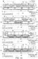
- FIG. 9 is a view for explaining a preform shaping method using a preform shaping apparatus according to the fifth embodiment of the present invention.
- a method of shaping a preform using a preform shaping apparatus 1D in the fifth embodiment shown in FIG. 9 is different from the method of shaping a preform using the preform shaping apparatus 1 in the first embodiment in a point that a pressurizing jig 9A for pressing the material M, before shaping a preform, to the lower mold 2 at different positions and timing is composed of a rigid upper mold 60 and closed pressure bags 62. Since other structures and actions in the fifth embodiment are not substantially different from those in the first embodiment, explanation for the same or corresponding elements is omitted with attaching the same signs.
- the pressure may be also applied on the material M by pressing the rigid upper mold 60 to the material M without utilizing the atmospheric pressure.
- the outer vacuum bag 4 used as an element of the pressurizing jig 9 in order to apply the atmospheric pressure in the first embodiment is not used as an element of the pressurizing jig 9A in the fifth embodiment.
- the pressure bags 62 which are inflated by injecting air at the time of shaping the material M are used as elements of the pressurizing jig 9A in the fifth embodiment.
- the unshaped material M can be placed on the convex portions 2A of the lower mold 2.
- the deflated pressure bags 62 can be placed on the unshaped material M.
- the respective pressure bags 62 have shapes which fit to the concave portions of the lower mold 2 respectively once air has been injected inside the pressure bags 62.
- the respective pressure bags 62 are placed at positions opposed to the corresponding concave portions across the material M respectively.
- the upper mold 60 having a flat surface can be pressed to the material M on which the deflated pressure bags 62 have been placed.
- the deflated pressure bags 62 each having a closed bag structure can be placed at different positions between the material M and the additional rigid upper mold 60 for sandwiching the material M with the lower mold 2.
- the upper mold 60 can be moved in the vertical direction with a moving structure 61, such as a general purpose pressing machine, for example. Note that, the upper mold 60 may be fixed while the lower mold 2 may be moved with an elevator or the like since the atmospheric pressure is not used.
- a moving structure 61 such as a general purpose pressing machine, for example. Note that, the upper mold 60 may be fixed while the lower mold 2 may be moved with an elevator or the like since the atmospheric pressure is not used.
- the pressure bags 62 can be inflated sequentially at different timing in a state where the material M has been held between the lower mold 2 and the upper mold 60. Consequently, the material M can be pressed on the lower mold 2 at different positions and timing by forces applied on the material M from the pressure bags 62 at different timing.
- An order of inflating the pressure bags 62 can be determined similarly to an order of deflating the inner vacuum bags 3 in the first embodiment. That is, an order of inflating the pressure bags 62 can be determined so that the material M may not be pulled to both sides across each convex portion 2A.
- a tube 62A can be attached to each pressure bag 62, similarly to each inner vacuum bag 3.
- Each tube 62A can be coupled to a common pipe 63 through the cock 8.
- the pressure bags 62 can be inflated by injecting air into their insides using a common air supply device 64 at different timing by opening and closing the cock 8.
- the air supply devices 64 may be coupled to the respective pressure bags 62 separately.
- the pressurizing jig 9A is composed of the rigid upper mold 60 and the pressure bags 62
- a composite material is molded by the RTM method using the preform shaping apparatus ID, what is necessary is to install at least one injecting pipe 65, for injecting resin into a shaped dry preform, in the lower mold 2, the upper mold 60 or an end part of the dry preform while coupling at least one pipe 66 for vacuuming to the lower mold 2.
- the injecting pipes 65 for injecting the resin have been embedded in portions of the upper mold 60 for pressing the fibers on the convex portions 2A of the lower mold 2 respectively so that the resin may certainly permeate respective mountain portions of the corrugated dry preform where it is important to spread the resin.
- the pipes 66 which open in the concave portions of the lower mold 2 respectively have been coupled to a vacuum device 67.
- a laminated body of prepregs can be used as the material M, and a composite material can be molded by thermally curing a shaped preform with an oven, an autoclave apparatus or the like.
- the preform shaping apparatus 1D can be used as a device for thermally curing the composite material.
- a preform having a complicated shape with concavity and convexity such as a corrugated preform, can be shaped with high quality, using the upper mold 60 having a simple structure without concavity and convexity.
- the rigid plates 50 as explained in the second embodiment may be used in the fifth embodiment.
- the plate 50 can be interposed between each pressure bag 62 and the material M.
- the material M can be deformed along the corners formed in the concave portions of the lower mold 2 more certainly.
- the plurality of the pressure bags 62 may be placed between the adjacent two convex portions 2A of the lower mold 2, similarly to the third embodiment. In this case, the pressure bags 62 can be inflated sequentially in an order similar to that in the third embodiment.
- the preform can be shaped by disposing the pressure bags 62 on the lower mold 2 having a curved surface, and sequentially inflating the pressure bags 62 between the lower mold 2 and the upper mold 60.
- FIG. 10 is a view for explaining a preform shaping method using a preform shaping apparatus according to the sixth embodiment of the present invention.
- a method of shaping a preform using a preform shaping apparatus 1E in the sixth embodiment shown in FIG. 10 is different from the method of shaping a preform using the preform shaping apparatus 1 in the first embodiment in a point that a pressurizing jig 9B for pressing the material M, before shaping a preform, to the lower mold 2 at different positions and timing is composed of separated rigid upper molds 70. Since other structures and actions in the sixth embodiment are not substantially different from those in the first embodiment, explanation for the same or corresponding elements is omitted with attaching the same signs.
- the material M can be placed on the lower mold 2, and subsequently the rigid upper molds 70 for applying pressures on the material M at different positions can be sequentially pressed to the material M at different timing as shown by (B), (C) and (D) of FIG. 10 .
- each upper mold 70 has a shape fitting one of the concave portions of the lower mold 2. Therefore, the material M can be fitted to the respective concave portions of the lower mold 2.
- the upper molds 70 can be respectively moved in the vertical direction by moving structures 71, such as general-purpose pressing machines, for example.
- Each moving structure 71 may be manually driven with switch operation by an operator, or automatically controlled by a controlling device 72, composed of electronic circuits or the like, as shown in FIG. 10 .
- An order of moving the upper molds 70 downward to depress the material M can be determined similarly to an order of deflating the inner vacuum bags 3 in the first embodiment. Specifically, an order of depressing the upper molds 70 toward the concave portions of the lower mold 2 can be determined so that the material M may not be pulled to both sides across each convex portion 2A.
- the pressurizing jig 9B is composed of the rigid upper molds 70
- a composite material is molded by the RTM method using the preform shaping apparatus IE, what is necessary is to dispose at least one injecting pipe 73, for injecting resin to a shaped dry preform, in the lower mold 2, at least one of the upper molds 70, at least one of clearances formed between the upper molds 70, or an end of a dry preform while coupling at least one pipe 66 for vacuuming to the lower mold 2.
- the injecting pipes 73 for injecting resin toward fibers, pressed to the convex portions 2A of the lower mold 2, from the clearances formed between the adjacent upper molds 70 have been disposed respectively so that the resin may certainly permeate the mountain portions of the corrugated dry preform where it is important to spread the resin.
- the pipes 66 opening in the concave portions of the lower mold 2 respectively have been coupled to the vacuum device 67.
- a laminated body of prepregs can be used as the material M, and a composite material can be molded by thermally curing a shaped preform with an oven, an autoclave apparatus or the like.
- the preform shaping apparatus 1E can be used as a device for thermally curing the composite material.
- a preform having a complicated shape with concavity and convexity such as a corrugated preform
- a corrugated preform can be shaped with more satisfactory quality.
- labor of operators and labor time can be reduced since setting closed bladder bags and bagging work with a bagging film become unnecessary.
Abstract
Description
- Embodiments described herein relate generally to a preform shaping apparatus, a method of shaping a preform and a method of producing a composite material structure.
- A typical wing structural object of an aircraft has a structure in which reinforcing structural members, such as spars, ribs and stringers, have been disposed between an upper panel (skin) and a lower panel. Moreover, a structural member having a corrugated cross section is known as one of structural members which reinforce a wing structural object (for example, refer to Japanese Patent Application Publication
JP HI 1-99 993 A - When a corrugated structural member is produced using a composite material, such as GFRP (glass fiber reinforced plastics) or CFRP (carbon fiber reinforced plastics), which is a resin reinforced with fibers, it is necessary to mold the composite material into a corrugated-shape.
- Typical methods of molding composite material include a method for laminating prepregs, which are fiber sheets impregnated with uncured thermosetting resin, and subsequently thermally curing the laminated prepregs with an autoclave apparatus or an oven, and an RTM (resin transfer molding) method for impregnating fiber sheets with thermosetting resin after laminating the fiber sheets, and subsequently thermally curing the thermosetting resin.
- In particular, a method of impregnating fibers with resin by vacuuming is called a VaRTM (vacuum assisted resin transfer molding) method. Moreover, a hybrid method which uses the RTM method together with a method for laminating prepregs, and subsequently, thermally curing the laminated prepregs is also known as a method of molding composite material.
- Therefore, in order to mold a corrugated composite material, it is required to shape a laminated body of prepregs into a corrugated shape, or to shape a laminated body of fiber sheets into a corrugated shape. A laminated body of prepregs shaped according to a shape of a composite material, a laminated body of fibers which has not been impregnated with resin in an RTM method and a laminated body of fibers which has been impregnated with resin in an RTM method are each called a preform in the technical field of molding composite material. In particular, a laminated body of fibers which has not been impregnated with resin is called a dry preform.
- Methods of shaping a corrugated preform include a method for laminating prepreg sheets on a shaping mold having corrugated concavity and convexity (for example, refer to Japanese Patent Application Publication
JP HI 1-99 993 A - As a method for molding a corrugated composite material, an RTM method can also be adopted (for example, refer to Japanese Patent Application Publication
JP HI 1-99 993 A - Methods of shaping a dry preform prior to molding a composite material include a method for laminating fibers on a shaping mold, and subsequently, heating the laminated fibers with a heater or the like (for example, refer to Japanese Patent Application Publication
JP 2006-123 404 A JP 2010-126 573 A - However, when a dry preform having a complicated shape including concavity and convexity, such as a corrugated dry preform, is shaped, bagging may become difficult. Specifically, when fiber sheets laminated on a shaping mold having concavity and convexity are locally pressed on convex portions of the shaping mold by the atmospheric pressure, the fiber sheets are pulled to the both sides across each convex portion.
- As a result, the fibers are stretched, and thereby may not fit to concavity portions of the shaping mold. In this case, a cavity is generated in each corner of the concavity portions of the shaping mold, and thereby it becomes difficult to produce a preform having an intended shape.
- Accordingly, an object of the present invention is to make it possible to produce a preform and a composite material having a complicated shape with satisfactory quality.
- In general, according to one embodiment of the invention, a preform shaping apparatus includes a rigid mold and a pressurizing jig. The rigid mold has a shape corresponding to a shape of a preform which has been shaped. The pressurizing jig presses an unshaped material of the preform to the rigid mold at different positions and different timing.
- Further, according to one embodiment of the invention, a method of shaping a preform includes: producing the shaped preform by pressing an unshaped material of the preform to a rigid mold at different positions and different timing; and using a pressurizing jig for pressing the material. The rigid mold has a shape corresponding to a shape of the preform. The pressurizing jig is adapted to apply pressures on the material at the different positions and the different timing.
- Further, according to one embodiment of the invention, a method of producing a composite material includes: placing core jigs on a laminated body of prepregs for a panel and placing the corrugated dry preform, produced by the above-mentioned method, on the placed core jigs; impregnating the corrugated dry preform with uncured thermosetting resin by injecting the uncured thermosetting resin into an area sealed by a vacuum bag in a state where the corrugated dry preform placed on the core jigs has been bagged with the vacuum bag; and producing the composite material structure having the panel and a corrugated reinforcing member attached to the panel, by thermally curing the laminated body of the prepregs for the panel and the thermosetting resin with which the corrugated dry preform has been impregnated.
- The laminated body of the prepregs for the panel is placed on a lower rigid mold. The core jigs correspond to a shape of the corrugated dry preform.
- Further, according to one embodiment of the invention, a method of producing a composite material structure includes: molding a corrugated composite material; producing a panel made of another composite material; and producing the composite material structure having the panel and a corrugated reinforcing member attached to the panel, by assembling the corrugated composite material to the panel. The corrugated dry preform or the corrugated laminated body of the prepregs, produced by the above-mentioned method, is used as a material of the corrugated composite material.
- In the accompanying drawings:
- FIG. 1
- is a view for explaining a preform shaping method using a preform shaping apparatus according to the first embodiment of the present invention;
- FIG. 2
- is a top view of the preform shaping apparatus shown by (A) in
FIG. 1 ; - FIG. 3
- is a view for explaining a problem in the conventional method of shaping a dry preform;
- FIG. 4
- is a view for explaining a method of integrally molding a composite material structure composed of a panel and a corrugated reinforcing member attached to the panel, using a dry preform produced with the preform shaping apparatus shown in
FIG. 1 ; - FIG. 5
- is a view for explaining a method of producing a composite material structure, composed of the panel and the corrugated reinforcing member attached to the panel, by assembling the panel produced separately from the corrugated reinforcing member produced by the preform shaping apparatus shown in
FIG. 1 ; - FIG. 6
- is a view for explaining a preform shaping method using a preform shaping apparatus according to the second embodiment of the present invention;
- FIG. 7
- is a view for explaining a preform shaping method using a preform shaping apparatus according to the third embodiment of the present invention;
- FIG. 8
- is a view for explaining a preform shaping method using a preform shaping apparatus according to the fourth embodiment of the present invention;
- FIG. 9
- is a view for explaining a preform shaping method using a preform shaping apparatus according to the fifth embodiment of the present invention; and
- FIG. 10
- is a view for explaining a preform shaping method using a preform shaping apparatus according to the sixth embodiment of the present invention.
- A preform shaping apparatus, a method of shaping a preform and a method of producing a composite material structure according to embodiments of the present invention will be described with reference to the accompanying drawings.
-
FIG. 1 is a view for explaining a preform shaping method using a preform shaping apparatus according to the first embodiment of the present invention, andFIG. 2 is a top view of the preform shaping apparatus shown by (A) inFIG. 1 . - A
preform shaping apparatus 1 produces a preform, having an intended shape, by shaping a material M. A preform to be produced may be a dry preform, consisting of fiber sheets which have not been impregnated with uncured thermosetting resin, or a thermally uncured composite material, consisting of fiber sheets which have been impregnated with uncured thermosetting resin. - When a dry preform is to be shaped, the material M is a laminated body of sheet-like fibers. A shaped dry preform is used as a material for molding a composite material under an RTM method. Specifically, a composite material is molded by impregnating a dry preform with uncured thermosetting resin and thermally curing the thermosetting resin with an autoclave apparatus or an oven. Therefore, a dry preform shaped with the
preform shaping apparatus 1 may be continuously impregnated with resin and thermally cured. In other words, thepreform shaping apparatus 1 may also be used as a molding apparatus of a composite material. - Meanwhile, when a preform made of fibers impregnated with resin is to be shaped by the
preform shaping apparatus 1, the preform can be produced by either impregnating a shaped dry preform with resin, or shaping a laminated body of prepregs. Therefore, when a preform in a state that fibers have been impregnated with resin is to be shaped by thepreform shaping apparatus 1, the material M is a laminated body of sheet-like fibers or a laminated body of sheet-like prepregs. -
FIG. 1 shows an example of a case of producing a dry preform having a corrugated cross section by shaping fibers which have been laminated in a sheet shape. Accordingly, a case where a corrugated dry preform is shaped by thepreform shaping apparatus 1 will be explained as an example with reference toFIG. 1 hereinafter. - A corrugated dry preform is used as a material of a corrugated reinforcing member, such as a corrugated stringer, a corrugated rib or a corrugated spar, made of a composite material. A corrugated reinforcing member is used as a part of a wing structure of an aircraft. Specifically, a corrugated reinforcing member is mainly attached to an upper panel or a lower panel as a member for reinforcing the panel.
- The
preform shaping apparatus 1 can be composed of alower mold 2,inner vacuum bags 3 and anouter vacuum bag 4 as shown by (A) ofFIG. 1 . Theinner vacuum bags 3 are disposed at concave portions of thelower mold 2 respectively, and the unshaped material M is placed on thelower mold 2 and theinner vacuum bags 3. Then, the material M is covered with theouter vacuum bag 4. - The
lower mold 2 is a rigid mold which has a shape corresponding to a shaped preform. Therefore, when a corrugated dry preform is shaped, thelower mold 2 has corrugated concavity and convexity on the surface as shown inFIG. 1 . Specifically, in order to shape projecting portions of a corrugated dry preform,convex portions 2A, each having an elongated structure, are formed on the surface of thelower mold 2. The length of eachconvex portion 2A formed on the surface of thelower mold 2 may be adjusted with the width of a dry preform, or may be made longer than the width of a dry preform. - Each
inner vacuum bag 3 has flexibility and a closed bag structure, and is disposed between thelower mold 2 and the material M. Specifically, theinner vacuum bags 3 each having a closed structure are respectively placed between theconvex portions 2A of thelower mold 2 for shaping projecting portions of a corrugated dry preform. Therefore, eachinner vacuum bag 3 has a hollow tubular structure of which both ends have been closed. The material M consisting of an unshaped flat sheet-like fiber bundles can be placed on thelower mold 2 where the inflatedinner vacuum bags 3 have been placed at corresponding concave portions respectively. - A
tube 3A for vacuuming is coupled to at least one end part of eachinner vacuum bag 3. Alternatively, a hole for vacuuming may be formed on each concave portion formed between the two adjacentconvex portions 2A of thelower mold 2 while a suction port is formed on eachinner vacuum bag 3 so that the suction ports formed on theinner vacuum bags 3 may be coupled to the holes for vacuuming formed on thelower mold 2 respectively. - The
outer vacuum bag 4 is a bagging film for sealing at least the atmosphere side of the material M in order to bag the material M. Therefore, atube 4A for vacuuming is also coupled to theouter vacuum bag 4. The material M is sealed by theouter vacuum bag 4 from outside in a state where theinner vacuum bags 3 have been disposed on thelower mold 2. In other words, the material M is disposed between theouter vacuum bag 4 and a set of theinner vacuum bags 3 and theconvex portions 2A of thelower mold 2. - As a concrete example, the whole
lower mold 2 on which theinner vacuum bags 3 and the material M have been placed can be covered by theouter vacuum bag 4, and the edge of theouter vacuum bag 4 can be stuck on the flat portion of thelower mold 2 by asealant 5, as shown inFIG. 2 . Alternatively, when the length of eachconvex portion 2A formed on the surface of thelower mold 2 is longer than the width of a dry preform, the end parts of eachconvex portion 2A may be exposed outside theouter vacuum bag 4. In that case, the edge of theouter vacuum bag 4 is stuck on theconvex portions 2A of thelower mold 2 by thesealant 5. - The end part of the
tube 3A attached to eachinner vacuum bag 3 is led to the outside of theouter vacuum bag 4 in order to be coupled to thevacuum device 6. Therefore, it is suitable to stick a clearance gap between eachtube 3A and thelower mold 2 as well as a clearance gap between eachtube 3A and theouter vacuum bag 4 by thesealant 5 from a viewpoint of keeping satisfactory airtightness in an area covered by theouter vacuum bag 4. - Note that, the
tube 4A for evacuating air from a space inside theouter vacuum bag 4 may be formed on thelower mold 2 instead of coupling to theouter vacuum bag 4. - Vacuuming of the area sealed by the
outer vacuum bag 4 and vacuuming of the inside of eachinner vacuum bag 3 are performed at different timing. Specifically, the vacuuming of the inside of eachinner vacuum bag 3 is performed at an appropriate timing after the vacuuming of the area sealed by theouter vacuum bag 4. - Also in such a case, the vacuuming of the area sealed by the
outer vacuum bag 4 and the vacuuming of the inside of eachinner vacuum bag 3 can be performed using thecommon vacuum device 6 by coupling apipe 7 as exemplified inFIG. 1 andFIG. 2 . Specifically, therespective tubes 3A of theinner vacuum bags 3 and thetube 4A of theouter vacuum bag 4 can be coupled to thecommon pipe 7 throughcocks 8 respectively. Thus, an operator can determine timing of vacuuming by opening and closing eachcock 8 manually. - Alternatively, each
cock 8 may be composed of an electric, hydraulic or pneumatic cock automatically opening and closing, and opening and closing of eachcock 8 may be automatically controlled with a controlling device. In that case, control signals for instructing timing of vacuuming can be generated in an electric circuit, a hydraulic circuit, or a pneumatic signal circuit composing the controlling device, and the generated control signals can be output to thecocks 8 respectively. Thereby, timing of vacuuming in theinner vacuum bags 3 and theouter vacuum bag 4 to which thecocks 8 have been coupled respectively can be automatically controlled. - As a matter of course, independent vacuum devices may be coupled to the
tubes 3A of theinner vacuum bags 3 and thetube 4A of theouter vacuum bag 4 respectively. In that case, an operator can determine timing for vacuuming by determining timing for switching the power supplies of the vacuum devices on respectively. Alternatively, the timing for driving each vacuum device may be automatically controlled by a controlling device which integrally controls operation of the respective vacuum devices. - The order of vacuuming in the
inner vacuum bags 3 performed after vacuuming in theouter vacuum bag 4 is determined as an order by which a space is not generated between the material M and thelower mold 2 even when the material M is pressed on thelower mold 2. In a case of shaping a corrugated dry preform, portions, in which spaces are most likely to be generated, between the material M and thelower mold 2 are concave round chamfered portions at both side corners of each concave portion formed between the adjacentconvex portions 2A. -
FIG. 3 is a view for explaining a problem in the conventional method of shaping a dry preform. - As shown by (A) of
FIG. 3 ,unshaped fiber sheets 11 can be placed on a conventional corrugatedlower mold 10 which hasconvex portions 10A each having an elongated structure, and then theunshaped fiber sheets 11 can be covered with abagging film 12. When the area covered with the baggingfilm 12 is evacuated by thevacuum device 13, the atmospheric pressure is applied in the thickness direction of thefiber sheets 11. - As a result, as shown by (B) of
FIG. 3 , thefiber sheets 11 deforms and are pressed to the bottoms of concave portions of thelower mold 10, and thereby thefiber sheets 11 in contact with theconvex portions 10A of thelower mold 10 are pulled toward both sides. Consequently, spaces are generated between thefiber sheets 11 and convex round chamfered portions formed at the rising portions of theconvex portions 10A. - Accordingly, the
preform shaping apparatus 1 evacuates the insides of theinner vacuum bags 3 in an appropriate order so that spaces may not be generated between the material M and the concave round chamfered portions of thelower mold 2. What is necessary in order to prevent spaces from being generated between the material M and the concave round chamfered portions of thelower mold 2 is to determine such an order of evacuating the insides of theinner vacuum bags 3 that the material M may be firstly pressed only to a desired concave portion selected out of the concave portions of the lower bold 10, and subsequently the material M may be pressed to adjacent one or two concave portions after the material M has contacted to the selected concave portion. - As a concrete example, as shown by (B) of
FIG. 1 , only the central concave portion of thelower mold 2 can be firstly selected as a target to which the material M is brought into contact. For that purpose, only theinner vacuum bag 3 placed in the central concave portion of thelower mold 2 can be evacuated. Meanwhile, each pressure inside the otherinner vacuum bags 3 can be made an approximate atmospheric pressure by opening the otherinner vacuum bags 3 to the atmospheric air beforehand. - As a result, only the
inner vacuum bag 3 placed in the central concave portion of thelower mold 2 deflates, and thereby the material M deforms toward the surface of the central concave portion. After that, the material M fits to the selected concave portion while sliding relative to theouter vacuum bag 4 and the two adjacentconvex portions 2A which form the central concave portion. - Next, as shown by (C) of
FIG. 1 , two concave portions in both sides adjacent to the central concave portion of thelower mold 2 can be selected as targets to which the material M are brought into contact. For that purpose, only the twoinner vacuum bags 3 placed in the two concave portions in both sides adjacent to the central concave portion of thelower mold 2 can be evacuated. Thereby, the material M can be slid and fitted to the two concave portions in both sides adjacent to the central concave portion of thelower mold 2. - After that, as shown by (D) of
FIG. 1 , the two concave portions adjacent in the further outsides can be selected as targets to which the material M are brought into contact. Then, the material M can be fitted to the two selected concave portions by evacuating only the two correspondinginner vacuum bags 3 . - Note that, although
FIG. 1 shows an example where the material M is sequentially fit to the concave portions of thelower mold 2 from the central concave portion toward outside concave portions, fitting of the material M may be started from another concave portion. For example, the material M may be sequentially fitted to the concave portions from the concave portion in one end side toward the concave portion in the other end side. Regardless of any case, it may be omitted to place theinner vacuum bag 3 in the concave portion to which the material M should be firstly fit. In that case, the material M can be fitted to the first concave portion by evacuating the inside of theouter vacuum bag 4. - When the material M is sequentially fitted to the concave portions of the
lower mold 2 from the center toward the outsides, the material M can be simultaneously pressed to two concave portions after pressing the material M to the central concave portion. Therefore, time required for shaping a preform can be shortened. - Meanwhile, when the material M is sequentially fitted to the concave portions of the
lower mold 2 from one end side toward the other end side, a direction of sliding the material M can be made one direction after pressing the material M to the first concave portion in one end side. Therefore, such a trouble that the end part of the material M lacks the length of a preform, or conversely that an excess surplus remains can be avoided. As a concrete example, when a corrugated dry preform of which both end parts are concave is shaped as exemplified inFIG. 1 , the material M can be shaped so that one edge of the material M may be coincided with one edge of a dry preform, and subsequently the material M can be slid in one direction and sequentially fitted to the other concave portions. - Thus, when the
inner vacuum bags 3 each substantially opened to the atmospheric air are placed in the area sealed by theouter vacuum bag 4, a shape deformation of the material M can be temporarily stopped while shaping of thefiber sheets 11 is started in the conventional shaping method as shown inFIG. 3 once the inside of thebagging film 12 is made a vacuum state. Therefore, a part of the material M can be shaped by selecting and evacuating a desiredinner vacuum bag 3. As a result, the material M can be certainly brought into contact to each concave corner portion of thelower mold 2, and thereby a preform which has a target shape can be produced. - Note that, the
tubes 3A attached to theinner vacuum bags 3 are desirable to be flatly crushed by evacuating the insides of theinner vacuum bags 3 respectively in the area sealed by theouter vacuum bag 4. Therefore, it is appropriate to make each of thetubes 3A attached to theinner vacuum bags 3 of a material having flexibility as well as theinner vacuum bags 3. - Moreover, the length of each
inner vacuum bag 3 may be made different from the length of a concave portion of thelower mold 2 without coinciding with the length of the concave portion of thelower mold 2, as exemplified inFIG. 2 . When the length of eachinner vacuum bag 3 is made long so that theinner vacuum bag 3 protrudes to the outside of the area sealed by theouter vacuum bag 4, air inflow into theouter vacuum bag 4 after evacuation can be prevented by sealing a clearance gap between theouter vacuum bag 4 and eachinner vacuum bag 3, and a clearance gap between eachinner vacuum bag 3 and thelower mold 2. - On the contrary, the length of each
inner vacuum bag 3 may be made shorter than the length of theconvex portion 2A of thelower mold 2. In that case, the edge portion of the material M is stretched between the adjacentconvex portions 2A immediately after evacuating the insides of theouter vacuum bags 4, and thereby spaces may be generated between the material M and thelower mold 2. Nevertheless, when the insides of theinner vacuum bags 3 are evacuated respectively, the edge portion of the material M deforms following deformations of the central portions of the material M. Therefore, not only the central portions of the material M but the edge portion can be brought into contact to the concave portions of thelower mold 2. - The material M is pressed on the rigid
lower mold 2, which has a form corresponding to a form of a shaped preform, at different timing and positions utilizing the atmospheric pressure. Therefore, it can be said that a pressurizingjig 9, which presses the material M before shaping a preform at different positions and timing, is formed by theinner vacuum bags 3 and theouter vacuum bag 4. - The
outer vacuum bag 4 composing the pressurizingjig 9 undertakes a role of applying a differential pressure between a pressure in the area sealed by theouter vacuum bag 4 and the atmospheric pressure, on the material M at different positions. Meanwhile, theinner vacuum bags 3 composing the pressurizingjig 9 are placed between thelower mold 2 and the material M, and undertake a role of pressing the material M on thelower mold 2 at different positions and timing by changing the timing of vacuuming. For that purpose, theinner vacuum bags 3 are placed at positions corresponding to the different positions for pressing the material M, i.e., the back side of the positions where the sheet like material M is pressed using the atmospheric pressure. - Thus, a shaped preform can be produced by pressing the material M at different positions and timing using the pressurizing
jig 9 composed of theinner vacuum bags 3 and theouter vacuum bag 4. - As mentioned above, a preform to be produced may be not only a dry preform but also a preform consisting of fibers which have been impregnated with resin. For example, a preform consisting of fibers which have been impregnated with resin can be produced by injecting uncured resin into the
outer vacuum bag 4 with maintenance of vacuuming of the insides of theouter vacuum bag 4 and theinner vacuum bags 3 after shaping a dry preform. In that case, an injection port for injecting resin is formed in theouter vacuum bag 4 or thelower mold 2. - Alternatively, a preform consisting of fibers which have been impregnated with resin can be produced by shaping the material M consisting of a laminated body of prepreg sheets instead of fiber sheets. That is, a corrugated laminated body of prepregs can be shaped as a preform.
- Moreover, a shape of a preform may be not only a corrugated shape but also a shape having a plurality of concave portions. Specifically, so long as the
lower mold 2 has at least two concave portions in which theinner vacuum bags 3 can be placed, an effect of preventing spaces between the material M and thelower mold 2 due to stretching the material M from being generated can be achieved by changing timing for evacuating the insides of theinner vacuum bags 3. Therefore, a dry preform or a laminated body of prepregs having concave portions can be shaped with thepreform shaping apparatus 1. - When the material M is shaped by the
preform shaping apparatus 1 composed of thelower mold 2, theinner vacuum bags 3 and theouter vacuum bag 4, it is necessary to slide the material M between theouter vacuum bag 4, and theconvex portions 2A of thelower mold 2 and theinner vacuum bags 3 . Accordingly, asheet 20 for sliding the material M to theconvex portions 2A of thelower mold 2 and theinner vacuum bags 3 may be placed at least between the material M, and thelower mold 2 and theinner vacuum bags 3. - In addition, when a dry preform is shaped, it is also important to prevent fray from being generated in fiber sheets. Therefore, it is desirable to shield both sides of sheet like fibers by the
sheets 20 as illustrated, from a viewpoint of smoothly sliding the fibers relative to thelower mold 2, theinner vacuum bags 3 and theouter vacuum bag 4 so as to prevent the generation of fray. - Meanwhile, also in a case that the material M is a laminated body of prepregs, it is required to smoothly slide the laminated body of prepregs relative to the
convex portions 2A of thelower mold 2, theinner vacuum bags 3 and theouter vacuum bag 4 without the adhesion. Accordingly, also when the material M is a laminated body of prepregs, it is desirable to shield both sides of the material M by thesheets 20 as illustrated. - The material of the
sheet 20 for smoothly sliding the material M may be polytetrafluoroethylene (PTFE), paper, polyethylene or the like. - Moreover, when a dry preform is shaped, it is desirable to place binder between layers of a laminated body of fiber sheets, which is used as the material M of the dry preform, from a viewpoint of keeping a form of the shaped dry preform more certainly. For example, a veil-shaped thermoplastic binder made of polyolefin, polyester, polyethylene, polypropylene, polyethylene terephthalate, polyamide, copolyester, or mixture thereof can be inserted among fiber sheets. Alternatively, powdered thermoplastic binder may be dredged among fibers. Moreover, rubber or epoxy binder may be used.
- When thermoplastic binder is placed among fiber layers, a dry preform is shaped by heating the binder with an oven or the like so that the binder may be melted. That is, a laminated body of fiber sheets including thermoplastic binder is shaped in high temperature environment in an oven. Then, when the laminated body of fiber sheets is cooled down to a normal temperature, the melted thermoplastic binder is cured again inside the shaped laminated body of fiber sheets, and thereby a shape of the dry preform can be kept.
- Moreover, fiber sheets including Z-threads for bearing strength in a thickness direction of a dry preform may also be used as the material M of the dry preform. Z-threads are fibers which bear strength in a thickness direction of fiber sheets, and fibers including Z-threads can be produced by weaving fibers spatially.
- A fabric of which fibers have been woven spatially is also called a three dimensional fabric. Practical examples include a three dimensional fabric where some fibers are disposed in a corrugated shape whose amplitude direction is a thickness direction of the fiber sheets.
- When a three dimensional fabric including Z threads is the material M of a dry preform, the dry preform can be shaped without using and heating thermoplastic binder. This is because a three dimensional fabric including Z threads has a function to keep a deformed shape.
- Next, a method of producing a composite material structure using the
preform shaping apparatus 1 will be described. -
FIG. 4 is a view for explaining a method of integrally molding a composite material structure composed of a panel and a corrugated reinforcing member attached to the panel, using a dry preform produced with thepreform shaping apparatus 1 shown inFIG. 1 . - Firstly, a corrugated dry preform is produced using the
preform shaping apparatus 1. For that purpose, in step S1, the inflatedinner vacuum bags 3 are placed between theconvex portions 2A of thelower mold 2 respectively. - Then, a laminated body of fiber sheets of which both sides are desirably shielded by the
sheets 20, such as PTFE, is placed, as the material M, on theinner vacuum bags 3 and theconvex portions 2A of thelower mold 2. In other words, theinner vacuum bags 3 are disposed between thelower mold 2 and the material M, at the opposite side of positions where the material M is pressed to the concave portions of thelower mold 2 using the atmospheric pressure respectively. - The laminated body of the fiber sheets used as the material M can be produced by laminating the fiber sheets on the
convex portions 2A of thelower mold 2 and theinner vacuum bags 3 with an automatic laminating device or manually by an operator, for example. Alternatively, the laminated body of the fiber sheets may be produced by laminating the fiber sheets on another rigid jig of which surface is flat. Moreover, a commercially available laminated body of fiber sheets may be placed on theconvex portions 2A of thelower mold 2 and theinner vacuum bags 3. - It is desirable to set powdered or veil-shaped thermoplastic binder between plies of the fiber sheets. Alternatively, a laminated body of fibers including Z-threads may also be used as the material M. When a laminated body of fibers including Z-threads is used as the material M, the use of the binder can be omitted.
- Then, the material M is sealed by the
outer vacuum bag 4 from the outside in a state where theinner vacuum bags 3 have been placed. Specifically, theouter vacuum bag 4 is stuck on thelower mold 2 by thesealant 5. Then, thetube 4A of theouter vacuum bag 4 is coupled to thepipe 7 for vacuuming. Meanwhile, the power supply of thevacuum device 6 is turned on, and thereby thevacuum device 6 drives. - Next, the
cock 8 attached to thetube 4A of theouter vacuum bag 4 is opened. At this time, therespective tubes 3A of theinner vacuum bags 3 are not coupled to thepipe 7, and the respectiveinner vacuum bags 3 are opened to the atmospheric air. Therefore, air is discharged only from a space among the respectiveinner vacuum bags 3 and theouter vacuum bag 4. - As a result, the closed area sealed by the
outer vacuum bag 4 becomes a vacuum state. Therefore, the respectiveinner vacuum bags 3 remains the inflated state, and the material M is supported on the inflatedinner vacuum bags 3 and theconvex portions 2A of thelower mold 2, in an approximately flat state, as shown by (A) ofFIG. 1 . - Next, in step S2, the
tubes 3A of theinner vacuum bags 3 are coupled to thepipe 7 for vacuuming, and the atmospheric temperature is increased with a heating device. Then, thecocks 8 attached to thetubes 3A of theinner vacuum bags 3 are sequentially opened at different timing. - As a result, air is sequentially discharged from the insides of the
inner vacuum bags 3, and the insides of theinner vacuum bags 3 become a vacuum state at the different timing. As a concrete example, the vacuuming is sequentially performed from the centralinner vacuum bag 3 toward theinner vacuum bags 3 in both end sides as shown by (B), (C) and (D) ofFIG. 1 . - Thereby, the
inner vacuum bags 3 sequentially deflate, and the material M is pushed against thelower mold 2 at the different positions and timing using the atmospheric pressure. At this time, the material M slides and moves between theouter vacuum bag 4, and theconvex portions 2A of thelower mold 2 and theinner vacuum bags 3 before vacuuming. The material M can be smoothly slid by shielding both sides of the material M by thesheets 20 made of PTFE or the like. - When the insides of all the
inner vacuum bags 3 have become a vacuum state and all theinner vacuum bags 3 have deflated, the material M contacts to the corrugatedlower mold 2 without clearances as shown by (D) ofFIG. 1 . When the material M is fibers including Z-threads and inserting thermoplastic binder is omitted, shaping of adry preform 30 is completed by pressing the material M to thelower mold 2 using the atmospheric pressure. That is, thedry preform 30 which has been shaped into a corrugated shape can be obtained. - Meanwhile, when thermoplastic binder is included in the material M, the material M is made to contact to the corrugated
lower mold 2 under a heating environment with an oven or the like. As a result, the thermoplastic binder melts inside the material M which has deformed into the corrugated shape. After that, when the temperature of the material M is returned to the normal temperature by air cooling or the like, the thermoplastic binder is cured again inside the material M which has deformed into the corrugated shape. Thereby, shaping of thedry preform 30 is completed. That is, thedry preform 30 which has been shaped into the corrugated shape can be obtained. - Meanwhile, in step S3, prepregs 32 for an upper panel or a lower panel are laminated on a rigid
lower mold 31 for molding a composite material. Thereby, a laminated body of theprepregs 32 for the panel is produced. - Next, in step S4, core jigs 33 formed according to the shape of the corrugated
dry preform 30 are placed on the laminated body of theprepregs 32 for the panel, which has been laminated on thelower mold 31. As necessary, jigs for positioning the core jigs 33 are used for placing the core jigs 33. - Next, in step S5, the corrugated
dry preform 30 produced by thepreform shaping apparatus 1 is set on the laminated body of theprepregs 32 for the panel and the core jigs 33. For that purpose, the corrugateddry preform 30 is previously removed from thepreform shaping apparatus 1. - Next, in step S6, the
dry preform 30 which has been set on the laminated body of theprepregs 32 for the panel and the core jigs 33 is bagged with avacuum bag 34. That is, the area sealed by thevacuum bag 34 is evacuated by avacuum device 35. Then, uncuredthermosetting resin 36 is injected into the area sealed by thevacuum bag 34. Thethermosetting resin 36 can be injected from a resin injection port formed in thevacuum bag 34 or thelower mold 31. - Alternatively, the
vacuum bag 34 may be sealed with the core jigs 33 and thelower mold 31 so that end portions of the core jigs 33 protrude outside thevacuum bag 34, and thethermosetting resin 36 may be injected from a resin injection port, formed in at least one of the core jigs 33, to the area sealed by thevacuum bag 34. Thereby, the corrugateddry preform 30 is impregnated with the uncuredthermosetting resin 36. - Next, in step S7, the
thermosetting resin 36 with which the laminated body of theprepregs 32 for the panel and the corrugated laminated body of fibers have been impregnated is thermally cured by aheating device 37, such as an oven or an autoclave apparatus. - Thereby, a
composite material structure 40 having apanel 38 and a corrugated reinforcingmember 39 attached to thepanel 38 can be produced. Thecomposite material structure 40 having thepanel 38 and the corrugated reinforcingmember 39 attached to thepanel 38 can be used as a part of a fuselage or a wing structure composing a main wing, a horizontal tail, a vertical tail or a center wing. - Although
FIG. 4 shows a method for integrally molding thecomposite material structure 40, having a structure in which the corrugated reinforcingmember 39 has been attached to thepanel 38, by a hybrid method by which the corrugated reinforcingmember 39 is produced by a VaRTM method while thepanel 38 is produced by laminating and thermally curing prepregs, thecomposite material structure 40 having thepanel 38 and the corrugated reinforcingmember 39 attached to thepanel 38 may also be produced by another molding method with thepreform shaping apparatus 1. -
FIG. 5 is a view for explaining a method of producing acomposite material structure 40A, composed of thepanel 38 and the corrugated reinforcingmember 39 attached to thepanel 38, by assembling thepanel 38 produced separately from the corrugated reinforcingmember 39 produced by thepreform shaping apparatus 1 shown inFIG. 1 . - Firstly, a corrugated laminated body of prepregs is produced using the
preform shaping apparatus 1. For that purpose, in step S20, the inflatedinner vacuum bags 3 are placed between theconvex portions 2A of thelower mold 2 respectively. - Then, a laminated body of prepreg sheets of which both sides are desirably shielded by the
sheets 20, such as PTFE, is placed, as the material M, on theinner vacuum bags 3 and theconvex portions 2A of thelower mold 2. In other words, theinner vacuum bags 3 are disposed between thelower mold 2 and the material M, at the opposite side of positions where the material M is pressed to the concave portions of thelower mold 2 using the atmospheric pressure respectively. - The laminated body of the prepregs laminated approximately flatly and used as the material M can be produced by laminating the prepreg sheets on the
convex portions 2A of thelower mold 2 and theinner vacuum bags 3 with an automatic laminating device or manually by an operator, for example. Alternatively, the laminated body of the prepreg may be produced by laminating the prepreg sheets on another rigid jig of which surface is flat. - Then, the material M is bagged by the
outer vacuum bag 4 while the insides of theinner vacuum bags 3 are kept at an approximately atmospheric pressure, similarly to the operation in step S1 ofFIG. 4 . Thus, the material M is kept in an approximately flat state on the inflatedinner vacuum bags 3 and theconvex portions 2A of thelower mold 2 as shown by (A) ofFIG. 1 . - Next, in step S21, the atmospheric temperature is increased by an oven or the like, and the insides of the
inner vacuum bags 3 are evacuated sequentially, similarly to the operation in step S2 ofFIG. 4 . Thereby, the material M consisting of the laminated body of the prepregs can be contacted to the corrugatedlower mold 2 without generating clearances, as shown by (D) ofFIG. 1 . As a result, alaminated body 41 of the prepregs which has been shaped into a corrugated shape can be produced. That is, a corrugated preform made of the fibers impregnated with the resin can be obtained. - Next, in step S22, the
laminated body 41 of the prepregs which has been shaped into the corrugated shape is thermally cured. Specifically, thelaminated body 41 of the prepregs bagged by theouter vacuum bag 4 is thermally cured by aheating device 37A, such as an oven or an autoclave apparatus. Thereby, the corrugated reinforcingmember 39 can be molded from the material consisting of the corrugatedlaminated body 41 of the prepregs. - Meanwhile, in step S23, the
panel 38 made of a composite material is produced by a desired molding method. For example, thepanel 38 made of the composite material can be produced by laminating prepregs for the panel on thelower mold 31 as shown in step S3 ofFIG. 4 , and subsequent thermal curing of the laminated prepregs with aheating device 37B, such as an oven or an autoclave apparatus. - Next, in step S24, the corrugated reinforcing
member 39 is assembled with thepanel 38 made of the composite material. For example, thepanel 38 made of the composite material can be placed on anassembly jig 42, and the corrugated reinforcingmember 39 can be attached to thepanel 38 using adhesive or fasteners. Thus, thecomposite material structure 40A having the structure in which the corrugated reinforcingmember 39 has been attached to thepanel 38 can be produced. - Besides the example shown in
FIG. 5 , a corrugated preform consisting of fibers impregnated with resin may be produced by a VaRTM method using a laminated body of fiber sheets as the material M. In that case, the corrugated reinforcingmember 39 can be molded by thermal curing of the preform, bagged with theouter vacuum bag 4, by an oven, an autoclave apparatus or the like. - In other words, the corrugated
dry preform 30 produced by thepreform shaping apparatus 1 in the example shown inFIG. 4 may not be removed from thepreform shaping apparatus 1, and continuously the corrugated reinforcingmember 39 can be molded by a VaRTM method. - Thus, the
preform shaping apparatus 1 can be used not only as an apparatus for shaping a preform but also as a composite material molding apparatus carried into an oven, an autoclave apparatus or the like to be used for thermal curing of a composite material. - As described above, the
preform shaping apparatus 1, the method of shaping a preform and the method of producing a composite material structure can bring the material M into contact to the concave portions of thelower mold 2 certainly by bagging theinner vacuum bags 3 together with the material M with theouter vacuum bag 4, and evacuating the insides of theinner vacuum bags 3 sequentially at different timing. - Therefore, according to the
preform shaping apparatus 1, the method of shaping a preform and the method of producing a composite material structure, a preform and a composite material having a complicated shape, which could not be produced with satisfactory quality by a conventional method, can be produced by a simple apparatus at low cost. That is, only thelower mold 2 can be needed as a shaping mold having concavity and convexity, by utilizing the atmospheric pressure. In other words, it is not necessary to produce an upper mold which has a complicated shape. - Moreover, laying the
sheets 20 made of PTFE or the like makes it possible to smoothly slide the material M relative to thelower mold 2, theinner vacuum bags 3, and theouter vacuum bag 4 while preventing disorder of fibers. -
FIG. 6 is a view for explaining a preform shaping method using a preform shaping apparatus according to the second embodiment of the present invention. - A method of shaping a preform using a
preform shaping apparatus 1A in the second embodiment shown inFIG. 6 is different from the method of shaping a preform using thepreform shaping apparatus 1 in the first embodiment in a point thatrigid plates 50 having shapes corresponding to the shapes of the concave portions of thelower mold 2 respectively are placed between theouter vacuum bag 4 and the material M. Since other structures and actions in the second embodiment are not substantially different from those in the first embodiment, explanation for the same or corresponding elements is omitted with attaching the same signs. - As shown in
FIG. 6 , therigid plates 50 which have shapes corresponding to the shapes of the concave portions of thelower mold 2 can be placed between theouter vacuum bag 4 and the material M. In this case, the material M is sandwiched between theinner vacuum bags 3 and theplates 50 as shown by (A) ofFIG. 6 . - Each
plate 50 can be made of a metal or a composite material which has necessary strength, for example. Moreover, eachplate 50 is made of a material which has the heat resistance to heating when thermoplastic binder is heated to be melted at the time of shaping a preform and when a composite material is thermally cured using thepreform shaping apparatus 1A. - Each
plate 50 has a shape whose width is equivalent to the distance between the adjacentconvex portions 2A. The length of eachplate 50 can be made equivalent to the length of theinner vacuum bag 3 or the length of theconvex portion 2A, for example. - When the material M is held between the
inner vacuum bags 3 and theplates 50 each having the appropriate width, as described above, therigid plates 50 can be fitted to the concave portions respectively after theinner vacuum bags 3 have been deflated, as shown by (B), (C) and (D) ofFIG. 6 . - As a result, the material M can be pressed to the round chamfered portions formed at the corners of the concave portions of the
lower mold 2 more certainly, as shown by (D) ofFIG. 6 , in a case where a dry preform or a laminated body of prepregs, having a plurality of concave portions, like a corrugated dry preform or a corrugated laminated body of prepregs is shaped. - That is, generation of clearances between the material M and the concave portions of the
lower mold 2 can be prevented more certainly. Therefore, it becomes possible to shape a preform with more satisfactory quality. -
FIG. 7 is a view for explaining a preform shaping method using a preform shaping apparatus according to the third embodiment of the present invention. - A method of shaping a preform using a
preform shaping apparatus 1B in the third embodiment shown inFIG. 7 is different from the method of shaping a preform using thepreform shaping apparatus 1 in the first embodiment in a point that a plurality of theinner vacuum bags 3 are placed in at least one of the concave portions of thelower mold 2. Since other structures and actions in the third embodiment are not substantially different from those in the first embodiment, explanation for the same or corresponding elements is omitted with attaching the same signs. - As shown by (A) of
FIG. 7 , two or moreinner vacuum bags 3 may be placed between the adjacent twoconvex portions 2A of thelower mold 2. In this case, theinner vacuum bags 3 between the adjacent twoconvex portions 2A can be sequentially evacuated at different timing. When the threeinner vacuum bags 3 are placed between each adjacentconvex portions 2A as shown by (A) ofFIG. 7 , and the material M is pressed to the central concave portion firstly, for example, theinner vacuum bag 3 disposed at the center in the center concave portion can be evacuated and deflated as shown by (B-1) ofFIG. 7 , and subsequently the twoinner vacuum bags 3 disposed at both sides can be evacuated and deflated as shown by (B-2) ofFIG. 7 . - Then, as for the two concave portions adjacent to the central concave portion, the
inner vacuum bags 3 can be evacuated and deflated sequentially from theinner vacuum bags 3 closest to the central concave portion as shown by (C-1), (C-2) and (C-3) ofFIG. 7 . Finally, theinner vacuum bags 3 disposed in the two concave portions in both end sides of thelower mold 2 where theconvex portion 2A stands in only one side can be evacuated and deflated as shown by (D) ofFIG. 7 . - Accordingly, the material M can be gradually pressed to each concave portion formed between the adjacent
convex portions 2A. Therefore, the distance by which the material M slides can be made not more than a constant distance, which can prevent disorder and wrinkle from being generated more certainly. Moreover, it is possible to prevent the material M from being pulled and stretched toward both sides between the adjacentconvex portions 2A, and thereby the material M can be pressed to the round chamfered portions formed at the corners of the concave portions of thelower mold 2 more certainly. -
FIG. 8 is a view for explaining a preform shaping method using a preform shaping apparatus according to the fourth embodiment of the present invention. - A method of shaping a preform using a
preform shaping apparatus 1C in the fourth embodiment shown inFIG. 8 is different from the method of shaping a preform using thepreform shaping apparatus 1 in the first embodiment in a point that a curved panel-shaped preform is shaped. Since other structures and actions in the fourth embodiment are not substantially different from those in the first embodiment, explanation for the same or corresponding elements is omitted with attaching the same signs. - As shown in
FIG. 8 , a convexly or concavely curved panel-shaped preform can be also shaped by thelower mold 2 and the pressurizingjig 9 composed of theinner vacuum bags 3 and theouter vacuum bag 4. That is, a dry preform or a laminated body of prepregs which has a curved structure can be shaped. - When a curved panel-shaped preform is shaped, a surface of the
lower mold 2 which is a rigid mold having a shape corresponding to that of a shaped preform has a curved shape without any local concavities and convexities. In an example shown inFIG. 8 , a concavely curved face has been formed on the surface of thelower mold 2. - As shown by (A) of
FIG. 8 , the inflatedinner vacuum bags 3 may be aligned on a curved surface of thelower mold 2. Then, the sheet-like material M of which both surfaces have been preferably covered with thesheets 20 made of PTFE or the like can be placed on theinner vacuum bags 3, and subsequently the atmosphere side of the material M can be bagged with theouter vacuum bag 4. - Then, as shown by (B) and (C) of
FIG. 8 , theinner vacuum bags 3 can be evacuated into the deflate state sequentially at different timing. Accordingly, the material M can be gradually pressed to the surface of thelower mold 2 while changing a shaping position of the material M. As a result, rapid deformation of the material M can be prevented, and thereby generating of disorder and wrinkle can be reduced. - Note that,
FIG. 8 shows an example of a case where the material M is pressed to the concavely curved surface of thelower mold 2 by arranging the threeinner vacuum bags 3 on the concavely curved surface of thelower mold 2, subsequently deflating the centralinner vacuum bag 3, and further subsequently deflating the twoinner vacuum bags 3 in both sides. As a matter of course, theinner vacuum bags 3 may be sequentially deflated from theinner vacuum bag 3 in one end side toward theinner vacuum bag 3 in the other end side. - As a matter of course, a preform having a rugged surface may be shaped although a degree of the curvature of the preform in the example shown in
FIG. 8 is relatively gentle. As a concrete example, even a preform, having a structure with a steep edge in the vertical direction, for which it is difficult to laminate fiber sheets or prepregs with an automatic laminating device, can be shaped. -
FIG. 9 is a view for explaining a preform shaping method using a preform shaping apparatus according to the fifth embodiment of the present invention. - A method of shaping a preform using a
preform shaping apparatus 1D in the fifth embodiment shown inFIG. 9 is different from the method of shaping a preform using thepreform shaping apparatus 1 in the first embodiment in a point that a pressurizingjig 9A for pressing the material M, before shaping a preform, to thelower mold 2 at different positions and timing is composed of a rigidupper mold 60 and closedpressure bags 62. Since other structures and actions in the fifth embodiment are not substantially different from those in the first embodiment, explanation for the same or corresponding elements is omitted with attaching the same signs. - As shown in
FIG. 9 , the pressure may be also applied on the material M by pressing the rigidupper mold 60 to the material M without utilizing the atmospheric pressure. In this case, theouter vacuum bag 4 used as an element of the pressurizingjig 9 in order to apply the atmospheric pressure in the first embodiment is not used as an element of the pressurizingjig 9A in the fifth embodiment. - Moreover, in place of the
inner vacuum bags 3 which are evacuated at the time of shaping the material M, thepressure bags 62 which are inflated by injecting air at the time of shaping the material M are used as elements of the pressurizingjig 9A in the fifth embodiment. - Specifically, as shown by (A) of
FIG. 9 , the unshaped material M can be placed on theconvex portions 2A of thelower mold 2. Subsequently, the deflatedpressure bags 62 can be placed on the unshaped material M. Therespective pressure bags 62 have shapes which fit to the concave portions of thelower mold 2 respectively once air has been injected inside thepressure bags 62. Moreover, therespective pressure bags 62 are placed at positions opposed to the corresponding concave portions across the material M respectively. - Then, the
upper mold 60 having a flat surface can be pressed to the material M on which the deflatedpressure bags 62 have been placed. In other words, the deflatedpressure bags 62 each having a closed bag structure can be placed at different positions between the material M and the additional rigidupper mold 60 for sandwiching the material M with thelower mold 2. - The
upper mold 60 can be moved in the vertical direction with a movingstructure 61, such as a general purpose pressing machine, for example. Note that, theupper mold 60 may be fixed while thelower mold 2 may be moved with an elevator or the like since the atmospheric pressure is not used. - Then, as shown by (B), (C) and (D) of
FIG. 9 , thepressure bags 62 can be inflated sequentially at different timing in a state where the material M has been held between thelower mold 2 and theupper mold 60. Consequently, the material M can be pressed on thelower mold 2 at different positions and timing by forces applied on the material M from thepressure bags 62 at different timing. An order of inflating thepressure bags 62 can be determined similarly to an order of deflating theinner vacuum bags 3 in the first embodiment. That is, an order of inflating thepressure bags 62 can be determined so that the material M may not be pulled to both sides across eachconvex portion 2A. - A
tube 62A can be attached to eachpressure bag 62, similarly to eachinner vacuum bag 3. Eachtube 62A can be coupled to acommon pipe 63 through thecock 8. Thereby, thepressure bags 62 can be inflated by injecting air into their insides using a commonair supply device 64 at different timing by opening and closing thecock 8. As a matter of course, theair supply devices 64 may be coupled to therespective pressure bags 62 separately. - When the material M is deforming toward each concave portion of the
lower mold 2, it slides to thelower mold 2 and theupper mold 60. Therefore, also when the pressurizingjig 9A is composed of the rigidupper mold 60 and thepressure bags 62, covering both surfaces of the material M with thesheets 20 made of PTFE or the like makes it possible to slide the material M smoothly. In addition, disorder of the fibers can also be prevented. - Also in the case where the pressurizing
jig 9A is composed of the rigidupper mold 60 and thepressure bags 62, it is possible to mold a composite material by an RTM method. When a composite material is molded by the RTM method using the preform shaping apparatus ID, what is necessary is to install at least one injectingpipe 65, for injecting resin into a shaped dry preform, in thelower mold 2, theupper mold 60 or an end part of the dry preform while coupling at least onepipe 66 for vacuuming to thelower mold 2. - In the example shown in
FIG. 9 , the injectingpipes 65 for injecting the resin have been embedded in portions of theupper mold 60 for pressing the fibers on theconvex portions 2A of thelower mold 2 respectively so that the resin may certainly permeate respective mountain portions of the corrugated dry preform where it is important to spread the resin. Meanwhile, thepipes 66 which open in the concave portions of thelower mold 2 respectively have been coupled to avacuum device 67. - As a matter of course, a laminated body of prepregs can be used as the material M, and a composite material can be molded by thermally curing a shaped preform with an oven, an autoclave apparatus or the like. In that case, the
preform shaping apparatus 1D can be used as a device for thermally curing the composite material. - According to the above-mentioned fifth embodiment, a preform having a complicated shape with concavity and convexity, such as a corrugated preform, can be shaped with high quality, using the
upper mold 60 having a simple structure without concavity and convexity. - Note that, the
rigid plates 50 as explained in the second embodiment may be used in the fifth embodiment. Specifically, theplate 50 can be interposed between eachpressure bag 62 and the material M. Thereby, the material M can be deformed along the corners formed in the concave portions of thelower mold 2 more certainly. Moreover, the plurality of thepressure bags 62 may be placed between the adjacent twoconvex portions 2A of thelower mold 2, similarly to the third embodiment. In this case, thepressure bags 62 can be inflated sequentially in an order similar to that in the third embodiment. As a matter of course, also in a case where a curved panel-shaped preform is shaped as described in the fourth embodiment, the preform can be shaped by disposing thepressure bags 62 on thelower mold 2 having a curved surface, and sequentially inflating thepressure bags 62 between thelower mold 2 and theupper mold 60. -
FIG. 10 is a view for explaining a preform shaping method using a preform shaping apparatus according to the sixth embodiment of the present invention. - A method of shaping a preform using a
preform shaping apparatus 1E in the sixth embodiment shown inFIG. 10 is different from the method of shaping a preform using thepreform shaping apparatus 1 in the first embodiment in a point that a pressurizingjig 9B for pressing the material M, before shaping a preform, to thelower mold 2 at different positions and timing is composed of separated rigidupper molds 70. Since other structures and actions in the sixth embodiment are not substantially different from those in the first embodiment, explanation for the same or corresponding elements is omitted with attaching the same signs. - As shown by (A) of
FIG. 10 , the material M can be placed on thelower mold 2, and subsequently the rigidupper molds 70 for applying pressures on the material M at different positions can be sequentially pressed to the material M at different timing as shown by (B), (C) and (D) ofFIG. 10 . - Thereby, the material M can be pressed to the
lower mold 2 at the different positions and timing. Eachupper mold 70 has a shape fitting one of the concave portions of thelower mold 2. Therefore, the material M can be fitted to the respective concave portions of thelower mold 2. - The
upper molds 70 can be respectively moved in the vertical direction by movingstructures 71, such as general-purpose pressing machines, for example. Each movingstructure 71 may be manually driven with switch operation by an operator, or automatically controlled by a controllingdevice 72, composed of electronic circuits or the like, as shown inFIG. 10 . - An order of moving the
upper molds 70 downward to depress the material M can be determined similarly to an order of deflating theinner vacuum bags 3 in the first embodiment. Specifically, an order of depressing theupper molds 70 toward the concave portions of thelower mold 2 can be determined so that the material M may not be pulled to both sides across eachconvex portion 2A. - When the material M is deforming toward each concave portion of the
lower mold 2, it slides to theconvex portions 2A of thelower mold 2. Therefore, inserting thesheet 20 made of PTFE or the like between the material M and thelower mold 2 makes it possible to slide the material M to thelower mold 2 smoothly. In addition, disorder of the fibers can also be prevented. - Also when the pressurizing
jig 9B is composed of the rigidupper molds 70, it is also possible to mold a composite material by the RTM method. When a composite material is molded by the RTM method using the preform shaping apparatus IE, what is necessary is to dispose at least one injectingpipe 73, for injecting resin to a shaped dry preform, in thelower mold 2, at least one of theupper molds 70, at least one of clearances formed between theupper molds 70, or an end of a dry preform while coupling at least onepipe 66 for vacuuming to thelower mold 2. - In the example shown in
FIG. 10 , the injectingpipes 73 for injecting resin toward fibers, pressed to theconvex portions 2A of thelower mold 2, from the clearances formed between the adjacentupper molds 70 have been disposed respectively so that the resin may certainly permeate the mountain portions of the corrugated dry preform where it is important to spread the resin. Meanwhile, thepipes 66 opening in the concave portions of thelower mold 2 respectively have been coupled to thevacuum device 67. - As a matter of course, a laminated body of prepregs can be used as the material M, and a composite material can be molded by thermally curing a shaped preform with an oven, an autoclave apparatus or the like. In that case, the
preform shaping apparatus 1E can be used as a device for thermally curing the composite material. - According to the above-mentioned sixth embodiment, a preform having a complicated shape with concavity and convexity, such as a corrugated preform, can be shaped with more satisfactory quality. Moreover, labor of operators and labor time can be reduced since setting closed bladder bags and bagging work with a bagging film become unnecessary.
- While certain embodiments have been described, these embodiments have been presented by way of example only, and are not intended to limit the scope of the invention. Indeed, the novel methods and systems described herein may be embodied in a variety of other forms; furthermore, various omissions, substitutions and changes in the shape of the methods and systems described herein may be made without departing from the spirit of the invention. The accompanying claims and their equivalents are intended to cover such forms or modifications as would fall within the scope and spirit of the invention.
Claims (14)
- A preform shaping apparatus comprising:a rigid mold having a shape corresponding to a shape of a preform which has been shaped; anda pressurizing jig that presses an unshaped material of the preform to the rigid mold at different positions and different timings.
- The preform shaping apparatus according to claim 1,
wherein the pressurizing jig includes:closed inner vacuum bags respectively disposed on positions,corresponding to the different positions, between the mold and the material; andan outer vacuum bag for sealing the material, on which the inner vacuum bags have been disposed, from an outside of the inner vacuum bags and the material,wherein the pressurizing jig presses the material to the mold using an atmospheric pressure, by evacuating an area sealed by the outer vacuum bag and evacuating insides of the inner vacuum bags at the different timings. - A method of shaping a preform comprising:producing the shaped preform by pressing an unshaped material of the preform to a rigid mold at different positions and different timings, the rigid mold having a shape corresponding to a shape of the preform; andusing a pressurizing jig for pressing the material, the pressurizing jig being adapted to apply pressures on the material at the different positions and the different timings.
- The method of shaping the preform according to claim 3, further comprising:respectively disposing closed inner vacuum bags on positions,corresponding to the different positions, between the mold and the material; andsealing, with an outer vacuum bag, the material, on which the inner vacuum bags have been disposed, from an outside of the inner vacuum bags and the material,wherein the material is pressed to the mold using an atmospheric pressure, by evacuating an area sealed by the outer vacuum bag and evacuating insides of the inner vacuum bags at the different timings.
- The method of shaping the preform according to claim 3,
wherein the material is pressed to the mold by pressing other rigid molds to the material at the different timings, the other rigid molds applying pressures on the material at the different positions. - The method of shaping the preform according to claim 3,
wherein the unshaped material is disposed on the mold while closed deflated pressurizing bags are disposed at the different positions between the material and another rigid mold for sandwiching the material between the rigid mold and the other rigid mold, and
the material is pressed to the mold by inflating the pressurizing bags at the different timings in a state where the material has been sandwiched between the rigid mold and the other rigid mold. - The method of shaping the preform according to claim 4,
wherein the shaped preform is a dry preform or a laminated body of prepregs, having concave portions, and
disposing rigid plates between the material and the outer vacuum bag in order to prevent gaps from being generated between the material and the rigid mold, the rigid plates having shapes corresponding to shapes of concave portions respectively. - The method of shaping the preform according to any one of claims 3 to 7,
wherein the shaped preform is a dry preform or a laminated body of prepregs, having a curved structure or concave portions. - The method of shaping the preform according to any one of claims 3 to 8,
wherein the shaped preform is a corrugated dry preform or a corrugated laminated body of prepregs. - The method of shaping the preform according to any one of claims 3 to 9,
wherein a sheet for sliding the material to the mold is disposed at least between the material and the mold. - The method of shaping the preform according to claim 8 or 9,
wherein thermoplastic binder is placed between layers of a laminated body of fiber sheets used as a material of the dry preform, and
the dry preform is shaped with heating and melting the thermoplastic binder. - The method of shaping the preform according to claim 8 or 9,
wherein fiber sheets including Z-threads bearing strength in a thickness direction of the dry preform is used as a material of the dry preform, and the dry preform is shaped without thermoplastic binder and heating. - A method of producing a composite material structure comprising:placing core jigs on a laminated body of prepregs for a panel and placing the corrugated dry preform, produced by the method according to claim 9, on the placed core jigs, the laminated body of the prepregs for the panel being placed on a lower rigid mold, the core jigs corresponding to a shape of the corrugated dry preform;impregnating the corrugated dry preform with uncured thermosetting resin by injecting the uncured thermosetting resin into an area sealed by a vacuum bag in a state where the corrugated dry preform placed on the core jigs has been bagged with the vacuum bag; andproducing the composite material structure having the panel and a corrugated reinforcing member attached to the panel, by thermally curing the laminated body of the prepregs for the panel and the thermosetting resin with which the corrugated dry preform has been impregnated.
- A method of producing a composite material structure comprising:molding a corrugated composite material, the corrugated dry preform or the corrugated laminated body of the prepregs, produced by the method according to claim 9, being used as a material of the corrugated composite material;producing a panel made of another composite material; andproducing the composite material structure having the panel and a corrugated reinforcing member attached to the panel, by assembling the corrugated composite material to the panel.
Applications Claiming Priority (2)
| Application Number | Priority Date | Filing Date | Title |
|---|---|---|---|
| JP2017171354 | 2017-09-06 | ||
| PCT/JP2018/014953 WO2019049411A1 (en) | 2017-09-06 | 2018-04-09 | Preform shaping device |
Publications (2)
| Publication Number | Publication Date |
|---|---|
| EP3680092A1 true EP3680092A1 (en) | 2020-07-15 |
| EP3680092A4 EP3680092A4 (en) | 2021-06-02 |
Family
ID=65635355
Family Applications (1)
| Application Number | Title | Priority Date | Filing Date |
|---|---|---|---|
| EP18853766.6A Pending EP3680092A4 (en) | 2017-09-06 | 2018-04-09 | Preform shaping device |
Country Status (5)
| Country | Link |
|---|---|
| US (1) | US11780188B2 (en) |
| EP (1) | EP3680092A4 (en) |
| JP (1) | JP6901575B2 (en) |
| CN (1) | CN110891772A (en) |
| WO (1) | WO2019049411A1 (en) |
Cited By (1)
| Publication number | Priority date | Publication date | Assignee | Title |
|---|---|---|---|---|
| EP3981582A1 (en) * | 2020-10-08 | 2022-04-13 | The Boeing Company | Methods and apparatuses for forming composite parts from multi-ply prepreg composite charges |
Families Citing this family (9)
| Publication number | Priority date | Publication date | Assignee | Title |
|---|---|---|---|---|
| JP6901575B2 (en) | 2017-09-06 | 2021-07-14 | 株式会社Subaru | Preform shaper |
| US11220072B2 (en) | 2020-01-02 | 2022-01-11 | The Boeing Company | Molding system and methods for forming structures |
| KR102292292B1 (en) * | 2020-02-04 | 2021-08-23 | 최석영 | Material forming apparatus and material forming method |
| TR202010823A1 (en) * | 2020-07-08 | 2022-01-21 | Tusas Tuerk Havacilik Ve Uzay Sanayii Anonim Sirketi | A composite paving mold production system. |
| US20230271375A1 (en) * | 2020-09-01 | 2023-08-31 | Mitsubishi Heavy Industries, Ltd. | Shaping device and shaping method |
| US20220134607A1 (en) * | 2020-10-30 | 2022-05-05 | GM Global Technology Operations LLC | Preform fiber placement on a three-dimensional surface |
| US20220184900A1 (en) * | 2020-12-11 | 2022-06-16 | Remarkable Foods, Inc. | Method and Apparatus For Forming a Composite Object |
| CN114734620B (en) * | 2022-05-10 | 2023-03-24 | 业成科技(成都)有限公司 | Concave surface attaching method |
| CN117484909B (en) * | 2023-11-02 | 2024-04-19 | 哈尔滨远驰航空装备有限公司 | Composite material airborne component, forming method and forming die thereof |
Family Cites Families (19)
| Publication number | Priority date | Publication date | Assignee | Title |
|---|---|---|---|---|
| US5648109A (en) * | 1995-05-03 | 1997-07-15 | Massachusetts Institute Of Technology | Apparatus for diaphragm forming |
| US5882462A (en) * | 1996-02-02 | 1999-03-16 | Dow-United Technologies Composite Products | Method for fabricating a corrugated composite channel |
| JPH1199993A (en) * | 1997-09-29 | 1999-04-13 | Fuji Heavy Ind Ltd | Composite material wing construction and manufacture thereof |
| JP2004322442A (en) * | 2003-04-24 | 2004-11-18 | Toray Ind Inc | Method and apparatus for producing frp preform |
| US7622066B2 (en) * | 2004-07-26 | 2009-11-24 | The Boeing Company | Methods and systems for manufacturing composite parts with female tools |
| JP4670313B2 (en) | 2004-10-29 | 2011-04-13 | 東レ株式会社 | Method for shaping reinforcing fiber base material for FRP molding |
| EP2047972B1 (en) * | 2007-10-09 | 2013-12-04 | Saab Ab | Method and device for shaping of composite material |
| JP2010126573A (en) | 2008-11-26 | 2010-06-10 | Nippon Zeon Co Ltd | Method for producing honeycomb core |
| KR101033476B1 (en) * | 2009-01-08 | 2011-05-09 | 주식회사 대한항공 | Folding and forming apparatus and method of prepreg |
| JP4734437B2 (en) * | 2009-04-17 | 2011-07-27 | 沓名 宗春 | Laser processing method for fiber reinforced composite material |
| JP5550370B2 (en) * | 2010-02-05 | 2014-07-16 | 本田技研工業株式会社 | Method for manufacturing aircraft wing structure |
| JP5646089B2 (en) * | 2011-12-06 | 2014-12-24 | 三菱電機株式会社 | Preform manufacturing method and fiber reinforced plastic molded body manufacturing method |
| DE102012200701A1 (en) * | 2012-01-18 | 2013-07-18 | Dieffenbacher GmbH Maschinen- und Anlagenbau | Method and device for producing a three-dimensional preform from a fiber fabric in the course of the production of fiber-reinforced molded parts |
| FR2995244B1 (en) * | 2012-09-07 | 2014-10-10 | Airbus Operations Sas | METHOD FOR MAKING A COMPOSITE MATERIAL PROFILE HAVING A RETRACTING ANGLE FROM A STACK OF FIBER LAYERS |
| US9738375B2 (en) * | 2013-12-05 | 2017-08-22 | The Boeing Company | One-piece composite bifurcated winglet |
| US9914268B2 (en) * | 2014-06-04 | 2018-03-13 | The Boeing Company | Systems and methods for defining a surface contour of a layered charge of material |
| US10118321B2 (en) * | 2016-01-05 | 2018-11-06 | The Boeing Company | Tooling apparatus and method for double-vacuum-bag degassing of a composite layup |
| JP6401859B2 (en) | 2016-09-29 | 2018-10-10 | 株式会社Subaru | COMPOSITE STRUCTURE AND METHOD FOR PRODUCING COMPOSITE STRUCTURE |
| JP6901575B2 (en) | 2017-09-06 | 2021-07-14 | 株式会社Subaru | Preform shaper |
-
2018
- 2018-04-09 JP JP2019540755A patent/JP6901575B2/en active Active
- 2018-04-09 WO PCT/JP2018/014953 patent/WO2019049411A1/en unknown
- 2018-04-09 EP EP18853766.6A patent/EP3680092A4/en active Pending
- 2018-04-09 CN CN201880047183.9A patent/CN110891772A/en active Pending
-
2020
- 2020-03-04 US US16/808,797 patent/US11780188B2/en active Active
Cited By (1)
| Publication number | Priority date | Publication date | Assignee | Title |
|---|---|---|---|---|
| EP3981582A1 (en) * | 2020-10-08 | 2022-04-13 | The Boeing Company | Methods and apparatuses for forming composite parts from multi-ply prepreg composite charges |
Also Published As
| Publication number | Publication date |
|---|---|
| CN110891772A (en) | 2020-03-17 |
| EP3680092A4 (en) | 2021-06-02 |
| US20200198185A1 (en) | 2020-06-25 |
| JP6901575B2 (en) | 2021-07-14 |
| US11780188B2 (en) | 2023-10-10 |
| WO2019049411A1 (en) | 2019-03-14 |
| JPWO2019049411A1 (en) | 2020-03-26 |
Similar Documents
| Publication | Publication Date | Title |
|---|---|---|
| US20200198185A1 (en) | Preform shaping apparatus | |
| JP5801885B2 (en) | Composite structure having integral stiffener and method for producing the same | |
| EP2253460B1 (en) | Method of joining composite components | |
| US11518494B2 (en) | Composite material structure and manufacturing method of composite material structure | |
| US5368807A (en) | Method for vacuum bag molding fiber reinforced resin matrix composites | |
| EP2318198B1 (en) | Method of assembling and shaping laminate panel and apparatus therefore | |
| EP3398759B1 (en) | Compacted stringer packages | |
| US20140166208A1 (en) | Preforming pre-preg | |
| US11701797B2 (en) | Composite material molding jig and composite material molding method | |
| US20100186893A1 (en) | System, method and apparatus for fabricating composite structures | |
| JP4721251B2 (en) | Manufacturing method of composite reinforcing plate | |
| US9415536B2 (en) | Apparatus and method for producing a composite material aircraft component | |
| JPWO2018198687A1 (en) | Composite molding jig, composite molding method and composite | |
| US20230373170A1 (en) | Preform shaping apparatus, preform shaping method and composite material molding method | |
| EP1775107B1 (en) | Moulding method with sliding layer | |
| US9545758B2 (en) | Two piece mandrel manufacturing system | |
| EP4212325A1 (en) | Beaded panels and systems and methods for forming beaded panels | |
| CN106142594B (en) | Apparatus and method for producing reinforced structures | |
| EP1775109B1 (en) | Composite moulding method and apparatus with a vacuum bag | |
| US20240025135A1 (en) | Method for producing composite molded body |
Legal Events
| Date | Code | Title | Description |
|---|---|---|---|
| STAA | Information on the status of an ep patent application or granted ep patent |
Free format text: STATUS: THE INTERNATIONAL PUBLICATION HAS BEEN MADE |
|
| PUAI | Public reference made under article 153(3) epc to a published international application that has entered the european phase |
Free format text: ORIGINAL CODE: 0009012 |
|
| STAA | Information on the status of an ep patent application or granted ep patent |
Free format text: STATUS: REQUEST FOR EXAMINATION WAS MADE |
|
| 17P | Request for examination filed |
Effective date: 20200304 |
|
| AK | Designated contracting states |
Kind code of ref document: A1 Designated state(s): AL AT BE BG CH CY CZ DE DK EE ES FI FR GB GR HR HU IE IS IT LI LT LU LV MC MK MT NL NO PL PT RO RS SE SI SK SM TR |
|
| AX | Request for extension of the european patent |
Extension state: BA ME |
|
| DAV | Request for validation of the european patent (deleted) | ||
| DAX | Request for extension of the european patent (deleted) | ||
| A4 | Supplementary search report drawn up and despatched |
Effective date: 20210430 |
|
| RIC1 | Information provided on ipc code assigned before grant |
Ipc: B29C 70/44 20060101AFI20210423BHEP Ipc: B29C 43/12 20060101ALI20210423BHEP Ipc: B29C 43/36 20060101ALI20210423BHEP Ipc: B29C 70/46 20060101ALI20210423BHEP Ipc: B30B 1/00 20060101ALI20210423BHEP Ipc: B30B 5/02 20060101ALI20210423BHEP Ipc: B29B 11/16 20060101ALI20210423BHEP Ipc: B29D 99/00 20100101ALI20210423BHEP Ipc: B29C 33/48 20060101ALI20210423BHEP |
|
| STAA | Information on the status of an ep patent application or granted ep patent |
Free format text: STATUS: EXAMINATION IS IN PROGRESS |
|
| 17Q | First examination report despatched |
Effective date: 20231012 |