EP3679999B1 - Procédé et installation de traitement d'un liquide - Google Patents
Procédé et installation de traitement d'un liquide Download PDFInfo
- Publication number
- EP3679999B1 EP3679999B1 EP19151001.5A EP19151001A EP3679999B1 EP 3679999 B1 EP3679999 B1 EP 3679999B1 EP 19151001 A EP19151001 A EP 19151001A EP 3679999 B1 EP3679999 B1 EP 3679999B1
- Authority
- EP
- European Patent Office
- Prior art keywords
- distillation column
- liquid
- exchanger
- evaporator
- transport
- Prior art date
- Legal status (The legal status is an assumption and is not a legal conclusion. Google has not performed a legal analysis and makes no representation as to the accuracy of the status listed.)
- Active
Links
Images

Classifications
-
- B—PERFORMING OPERATIONS; TRANSPORTING
- B01—PHYSICAL OR CHEMICAL PROCESSES OR APPARATUS IN GENERAL
- B01D—SEPARATION
- B01D1/00—Evaporating
- B01D1/28—Evaporating with vapour compression
- B01D1/2803—Special features relating to the vapour to be compressed
- B01D1/2812—The vapour is coming from different sources
-
- B—PERFORMING OPERATIONS; TRANSPORTING
- B01—PHYSICAL OR CHEMICAL PROCESSES OR APPARATUS IN GENERAL
- B01D—SEPARATION
- B01D1/00—Evaporating
- B01D1/28—Evaporating with vapour compression
- B01D1/284—Special features relating to the compressed vapour
- B01D1/2856—The compressed vapour is used for heating a reboiler or a heat exchanger outside an evaporator
-
- B—PERFORMING OPERATIONS; TRANSPORTING
- B01—PHYSICAL OR CHEMICAL PROCESSES OR APPARATUS IN GENERAL
- B01D—SEPARATION
- B01D3/00—Distillation or related exchange processes in which liquids are contacted with gaseous media, e.g. stripping
- B01D3/34—Distillation or related exchange processes in which liquids are contacted with gaseous media, e.g. stripping with one or more auxiliary substances
- B01D3/343—Distillation or related exchange processes in which liquids are contacted with gaseous media, e.g. stripping with one or more auxiliary substances the substance being a gas
- B01D3/346—Distillation or related exchange processes in which liquids are contacted with gaseous media, e.g. stripping with one or more auxiliary substances the substance being a gas the gas being used for removing vapours, e.g. transport gas
-
- B—PERFORMING OPERATIONS; TRANSPORTING
- B01—PHYSICAL OR CHEMICAL PROCESSES OR APPARATUS IN GENERAL
- B01D—SEPARATION
- B01D3/00—Distillation or related exchange processes in which liquids are contacted with gaseous media, e.g. stripping
- B01D3/34—Distillation or related exchange processes in which liquids are contacted with gaseous media, e.g. stripping with one or more auxiliary substances
- B01D3/38—Steam distillation
-
- C—CHEMISTRY; METALLURGY
- C02—TREATMENT OF WATER, WASTE WATER, SEWAGE, OR SLUDGE
- C02F—TREATMENT OF WATER, WASTE WATER, SEWAGE, OR SLUDGE
- C02F1/00—Treatment of water, waste water, or sewage
- C02F1/02—Treatment of water, waste water, or sewage by heating
- C02F1/04—Treatment of water, waste water, or sewage by heating by distillation or evaporation
- C02F1/041—Treatment of water, waste water, or sewage by heating by distillation or evaporation by means of vapour compression
-
- C—CHEMISTRY; METALLURGY
- C02—TREATMENT OF WATER, WASTE WATER, SEWAGE, OR SLUDGE
- C02F—TREATMENT OF WATER, WASTE WATER, SEWAGE, OR SLUDGE
- C02F1/00—Treatment of water, waste water, or sewage
- C02F1/02—Treatment of water, waste water, or sewage by heating
- C02F1/04—Treatment of water, waste water, or sewage by heating by distillation or evaporation
- C02F1/048—Purification of waste water by evaporation
Definitions
- the invention relates to a method and an installation for the treatment of liquids.
- This method and this installation will find a particular application for the treatment of effluents containing dissolved solvents, such as for example ammonia, or the treatment of petroleum liquids, and non-volatile impurities, such as salts or else fouling materials.
- dissolved solvents such as for example ammonia
- non-volatile impurities such as salts or else fouling materials.
- the soiled product is introduced continuously at the top of a distillation column (also called a “ stripping ” column) and spreads under the effect of gravity by flowing over a support, such as for example a straw-type packing. metallic, or a series of superimposed trays.
- a distillation column also called a “ stripping ” column
- a transport stream such as clean water vapor, is introduced at the bottom of the column. On its way up, this transport vapor exchanges and becomes charged with the volatile solvent contained in the product, which is therefore purified.
- the treated product is purified and recovered at the bottom of the column, while the outgoing transport vapor is condensed into a condensate heavily loaded with solvent.
- the present invention proposes to overcome the aforementioned drawbacks by proposing a treatment installation preventing any ebullioscopic delay in the exchanger and reducing the fouling and corrosion of the walls of the various elements of the installation, and in particular of the exchanger, even when the crude liquid to be treated comprises salts (NaCl, or KCl) in high concentration.
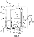
- Such a method with these steps executed simultaneously, allows said installation 1, shown in the exemplary embodiments of figures 1 and 2 , to process a crude liquid containing solvents and non-volatile impurities on a continuous basis.
- step (b) which takes place in the first distillation column 10
- these will not be found at any time in the other elements. of said installation 1, and in particular in the second distillation column 20, and especially the vaporizer exchanger 30.
- Step (h) of compression of the transport vapor VT VTS advantageously makes it possible to limit the vapor requirements of the installation 1 in order to implement the method according to the invention.
- the enthalpy of the vapor is increased, and therefore its temperature and pressure, which makes it possible to be able to reuse it during steps (b) and (f) of extraction of the solvents, intervening respectively in the first distillation column 10 and in the second distillation column 20, and therefore to limit the injection of new steam into the installation 1 in order to implement the process.
- step (h) of compressing the transport vapor VT can be carried out by compressor means 40, comprising for example a mechanical compressor, arranged downstream of the exchanger-evaporator 30 and upstream of the first distillation column 10 and the second distillation column 20.
- the compressor means 40 will perform compression on transport vapor VT, purified from solvents.
- step (h) of compression of the transport vapor VTS can be carried out by compressor means 40, comprising for example a mechanical compressor, arranged upstream of the exchanger-evaporator 30, and downstream of the first column of distillation 10 and of the second distillation column 20.
- the compressor means 40 will perform compression on the VTS transport vapor, loaded with solvents.
- the transport vapor VT and / or the liquid LV intended to be vaporized are purged from the exchanger-evaporator 30 by means of a purge system 60 during a step (j) .
- the transport vapor VT can be purged at the level of a transport vapor outlet 35 VT of the exchanger-evaporator 30, in particular an outlet 35 of purified transport vapor VT, ie not containing no solvents, for example upstream of the second distillation column 20 and of the first distillation column 10.
- the transport steam VT thus purged can optionally be used to supply a steam supply network separate from said installation 1.
- the liquid LV to be vaporized can be purged at the level of an outlet of liquid to be vaporized LV of the exchanger-evaporator 30, in particular an outlet of purified liquid to be vaporized LV, ie containing no solvents, for example downstream of the second distillation column 20 and upstream of the exchanger-evaporator 30.
- the liquid to be vaporized LV thus purged can optionally be used to supply a liquid supply network separate from said installation 1.
- Such a step (j) of purging the transport vapor VT and / or the liquid LV intended to be vaporized advantageously makes it possible to adjust the supply of transport vapor VT and / or of liquid to be vaporized LV from the installation 1. implementing the method according to the invention, for example in order to avoid overheating of the first 10 and / or of the second 20 distillation column, because of an excessively large quantity of transport vapor VT received.
- the non-volatile impurities of the crude liquid LB with which the installation 1 is supplied during step (b) comprise a salt, such as sodium chloride or potassium chloride.
- the salts contained in the raw liquids LB to be treated can degrade the operation of an installation implementing a process for treating liquids. Indeed, such salts will tend to create an ebulioscopic delay at the level of the steam generator device, the LV liquid intended to be vaporized, although no longer containing solvents, still contains the salts, which are not volatile particles. , and which cannot be extracted from a liquid via a distillation column.
- salts can cause fouling or corrosion of the various elements of the installation implementing a liquid treatment process.
- the salts are removed definitively from the installation 1 at the end of step (b), which takes place in the first distillation column 10, which becomes the only element of the installation to come into contact with the salts during the process according to the invention, thus having a “buffer effect” for the rest of the installation 1, including the elements, in particular the second distillation column 20, or else the exchanger-evaporator 30, will not come into contact with said salts.
- the non-volatile impurities of the crude liquid LB with which the installation 1 is supplied during step (b) comprise a fouling material.
- such a fouling material can consist of a leachate, or even a liquid phase of an anaerobic digestion digestate.
- Such fouling materials have harmful effects for an installation making it possible to implement a process for treating a liquid, similar to those of the salts described above.
- the fouling material will only come into contact with the first distillation column 10 of the installation 1, and will be permanently removed from the installation 1 at the end of step (b), preventing it in particular from fouling the other elements 20, 30 of the installation 1.
- Such an installation 1 can advantageously implement the method for treating a liquid according to the invention described above.
- Such an installation 1 also has the advantage that the non-volatile impurities, such as salts, for example NaCl or KCl, or fouling materials, such as leachate or methanization digestates, being evacuated at the level of the first distillation column 10 of said installation 1, do not come into contact with the other elements of the installation, in particular the second distillation column, the exchanger-evaporator 30 or even the compressor means 40.
- the non-volatile impurities such as salts, for example NaCl or KCl
- fouling materials such as leachate or methanization digestates
- Said trickling support means 12, 22 may be, in a manner known per se, in the form of superimposed trays or else in the form of a filling of the metal straw type.
- Each of the distillation columns 10, 20 forms a treatment chamber.
- the raw liquid LB to be treated comprising solvents and non-volatile impurities, is conveyed continuously into the installation 1 by means of the means 11 for conveying the liquids into the installation 1.
- the crude liquid LB to be treated is then introduced by the introduction means 11, in height, at the upper part of the first distillation column 10, while the transport vapor VT is introduced by the introduction means 13 to the lower part of the first distillation column 10.
- the transport vapor VT exchanges with the crude liquid LB to be treated and is charged with solvents.
- the non-volatile impurities are not carried by the transport vapor VT in the first distillation column 10 to the upper part of said first distillation column 10, but are recovered in a condensate LI containing the non-volatile impurities, in the lower part of said first distillation column 10 via recovery means 14 before being discharged via discharge means 15, while the transport vapor VTS, loaded with solvents, is discharged, in the upper part, of the first distillation column 10, by means of means 16 for evacuating the transport vapor VTS.
- non-volatile impurities will be permanently removed from installation 1 and will not interact with the other elements of installation 1.
- the steam generation device 30 comprises an exchanger-evaporator 30 comprising an inlet 31 for the liquid to be vaporized LV, an inlet 33 for a hot stream consisting of the transport vapor VTS leaving the first distillation column 10 and an outlet 39s for the vapor VT generated by said exchanger-evaporator 30 and intended to supply the first distillation column.
- Said exchanger-evaporator is advantageously provided with a primary 30P, provided to receive the transport vapor VTS loaded with solvents, which will provide heat to the liquid to be vaporized LV, and a secondary 30S provided to receive the liquid LV to be vaporized.
- Means 39i for recovering the transport vapor VT make it possible to recover the transport vapor VT, purified at the outlet of the secondary 30S of the exchanger-evaporator 30, in order to supply the first distillation column 10 and the second distillation column 20.
- An outlet 35 for transport vapor VT is provided in the lower part of the exchanger-evaporator and communicates with the means 13, 23 for introducing the transport vapor VT in the lower part of the first distillation column 10 and of the second distillation column 20.
- An outlet 34 is provided to extract the condensate CS loaded with solvents recovered in the lower part of the primary 30P of the exchanger-evaporator 30 and to feed the second distillation column 20, in the upper part, by means of the supply means 21 of the second LT liquid distillation column 20 to be treated, said liquid not comprising any non-volatile impurities.
- the second distillation column 20 comprises means 23 for introducing the transport vapor VT to the lower part of the second distillation column 20.
- the transport vapor VT exchanges with the liquid LT to be treated and is charged with solvents coming from the condensate CS coming from the exchanger-evaporator 30.
- the second distillation column 20 also comprises means 25 for evacuating the transport vapor VTS, loaded with solvents, in the upper part of the second distillation column 20 in order to supply the primary 30P of the exchanger-evaporator 30 by the intermediary of the means 33 for recovering the heat from the transport vapor VTS.
- the compressor means 40 which for example comprise a mechanical compressor, or even a thermocompressor, are provided to compress the transport vapor VT, purified from solvents, generated by the exchanger-evaporator 30, which is conveyed to the means of introduction 13, 23 of the first distillation column 10 and of the second distillation column 20.
- the compressor means 40 which may also comprise a mechanical compressor, or else a thermocompressor, are provided to compress the VTS transport vapor, loaded with solvents, between the means 16, 25 for recovering the VTS transport vapor, loaded with solvents, in the upper part of the first distillation column 10 and of the second distillation column and the inlet for the transport vapor VTS, loaded with solvents, of the exchanger-evaporator 30.
- the compressor means 40 do not compress the clean transport vapor VT (ie purified from solvents), as illustrated in the embodiment of the embodiment. figure 1 , but the VTS transport vapor, loaded with solvents.
- a purge system 60 may be provided in said installation 1 in order to purge the liquid to be vaporized LV, for example upstream of the exchanger-evaporator 30, and / or the transport vapor VT, for example downstream of the 'exchanger-evaporator 30.
- the exchanger-evaporator 30 also has a dewatering outlet 36 for the transport vapor VTCS having supplied its heat to said exchanger-evaporator, and heavily loaded with solvents, and in which a device for condensation 50, separate from said exchanger-evaporator 30, allows the VTCS vapor from said dewatering outlet 36 to be condensed.
- Said condensing device 50 can for example be a condensing unit heater.
- the condensates are wholly or partly recycled or extracted from said installation 1, in particular by undergoing fractional condensation.
- the liquid to be vaporized LV in said exchanger 30 is the purified liquid LV recovered in the lower part of the second distillation column 20 and which is conveyed by means of means 26 to the inlet 31 of said exchanger-evaporator 30.
- the secondary 30S of the exchanger-evaporator 30 is supplied with liquid to be vaporized LV, at the level of the inlet 31 for the liquid to be vaporized, by the liquid LV recovered in the lower part of the second column of distillation 20 by means of the means 24 for recovering the liquid to be vaporized LV.
- said second distillation column 20 also comprises means 24 for recovering the treated liquid LV having fallen in the lower part of the second distillation column 20, said liquid LV being purified from solvents, and being intended to supply the secondary 30S of the exchanger-evaporator 30, at the inlet 31, via feed means 26.
- This liquid LV is obviously purified from any non-volatile impurity, because it has already passed through the first distillation column 10.
- the secondary 30S of the exchanger-evaporator 30 takes the form of substantially vertical evaporation tubes 37 arranged in a heating chamber 38 constituting the primary 30P of the exchanger-evaporator 30, and has means 33 ensuring the introduction of the transport vapor VTS recovered in the chamber 38 and heating the outer wall of said evaporation tubes 37, means 39s for introducing the liquid to be vaporized LV into the evaporation tubes 37 at their upper part, as well as means 39i for recovering the liquid LV having passed through the evaporation tubes, the primary 30P of the exchanger being defined by the volume of the heating chamber 38 outside the tubes 37, the secondary 30S defined in inside the tubes 37.
- the purified water LV having fallen to the lower part of the second distillation column 20 is recovered and introduced by means 39s into the evaporation tubes 37 of the secondary 30S at their upper part.
- This water under the combined action of capillarity and gravity trickles inside the evaporation tubes, and is partially vaporized thanks to the heat transmitted by the wall of the tubes 37.
- the vapor VT produced descends in the tubes 37 and is discharged through the outlet 35 while a part of the liquid LV passes through the tubes 37 and is discharged at their lower part to be recovered in the means 39i; it is LV treated water, purified from solvents.
- the clean vapor VT generated by the exchanger-evaporator 30 is conveyed to said introduction means 13, 23 of the first 10 and of the second 20 distillation column, optionally being compressed by the compressor means 40.
Landscapes
- Chemical & Material Sciences (AREA)
- Chemical Kinetics & Catalysis (AREA)
- Life Sciences & Earth Sciences (AREA)
- Hydrology & Water Resources (AREA)
- Engineering & Computer Science (AREA)
- Environmental & Geological Engineering (AREA)
- Water Supply & Treatment (AREA)
- Organic Chemistry (AREA)
- Organic Low-Molecular-Weight Compounds And Preparation Thereof (AREA)
- Vaporization, Distillation, Condensation, Sublimation, And Cold Traps (AREA)
Priority Applications (4)
| Application Number | Priority Date | Filing Date | Title |
|---|---|---|---|
| PL19151001T PL3679999T3 (pl) | 2019-01-09 | 2019-01-09 | Sposób i instalacja do uzdatniania cieczy |
| DK19151001.5T DK3679999T3 (da) | 2019-01-09 | 2019-01-09 | Fremgangsmåde og anlæg til behandling af en væske |
| EP19151001.5A EP3679999B1 (fr) | 2019-01-09 | 2019-01-09 | Procédé et installation de traitement d'un liquide |
| ES19151001T ES2893578T3 (es) | 2019-01-09 | 2019-01-09 | Proceso e instalación de tratamiento de un líquido |
Applications Claiming Priority (1)
| Application Number | Priority Date | Filing Date | Title |
|---|---|---|---|
| EP19151001.5A EP3679999B1 (fr) | 2019-01-09 | 2019-01-09 | Procédé et installation de traitement d'un liquide |
Publications (2)
| Publication Number | Publication Date |
|---|---|
| EP3679999A1 EP3679999A1 (fr) | 2020-07-15 |
| EP3679999B1 true EP3679999B1 (fr) | 2021-07-07 |
Family
ID=65011914
Family Applications (1)
| Application Number | Title | Priority Date | Filing Date |
|---|---|---|---|
| EP19151001.5A Active EP3679999B1 (fr) | 2019-01-09 | 2019-01-09 | Procédé et installation de traitement d'un liquide |
Country Status (4)
| Country | Link |
|---|---|
| EP (1) | EP3679999B1 (da) |
| DK (1) | DK3679999T3 (da) |
| ES (1) | ES2893578T3 (da) |
| PL (1) | PL3679999T3 (da) |
Families Citing this family (1)
| Publication number | Priority date | Publication date | Assignee | Title |
|---|---|---|---|---|
| FR3115470B1 (fr) * | 2020-10-26 | 2023-01-13 | France Evaporation | Procédé de traitement d'un liquide contenant un solvant dissout et des impuretés non-volatiles |
Family Cites Families (3)
| Publication number | Priority date | Publication date | Assignee | Title |
|---|---|---|---|---|
| DE1114168B (de) * | 1960-08-03 | 1961-09-28 | Bayer Ag | Destillationsvorrichtung mit Waermepumpe |
| FR2939051B1 (fr) | 2008-12-03 | 2012-09-21 | France Evaporation | Installation de traitement de liquides notamment pour le traitement d'effluents |
| WO2010097318A1 (de) * | 2009-02-26 | 2010-09-02 | Basf Se | Verfahren zur destillativen aufarbeitung eines methanol/wasser-gemischs sowie verfahren zur herstellung von alkalimethylaten |
-
2019
- 2019-01-09 ES ES19151001T patent/ES2893578T3/es active Active
- 2019-01-09 EP EP19151001.5A patent/EP3679999B1/fr active Active
- 2019-01-09 DK DK19151001.5T patent/DK3679999T3/da active
- 2019-01-09 PL PL19151001T patent/PL3679999T3/pl unknown
Also Published As
| Publication number | Publication date |
|---|---|
| DK3679999T3 (da) | 2021-10-11 |
| PL3679999T3 (pl) | 2022-01-24 |
| EP3679999A1 (fr) | 2020-07-15 |
| ES2893578T3 (es) | 2022-02-09 |
Similar Documents
| Publication | Publication Date | Title |
|---|---|---|
| FR2773793A1 (fr) | Procede et systeme pour separer un glycol de courants de glycol/saumure | |
| CH631350A5 (fr) | Procede d'extraction d'une substance organique a partir d'une matiere vegetale au moyen de dioxyde de carbone liquide. | |
| FR2608461A1 (fr) | Installation et procede perfectionnes d'extraction de petrole, de gaz et de sous-produits a partir de schistes bitumineux et d'autres matieres impregnees d'hydrocarbures | |
| FR2495175A1 (fr) | Procede et circuit de pyrolyse de matiere cellulosique utilisant le recyclage de l'huile pyrolytique | |
| EP3679999B1 (fr) | Procédé et installation de traitement d'un liquide | |
| EP0873395B2 (fr) | Dispositif pour l'elimination des composants volatils non desires contenus dans un mout de biere | |
| WO2005105255A1 (fr) | Procede et installation de dessalement d'eau de mer par distillation a effets multiples avec compression mecanique et thermique, de vapeur | |
| FR2815966A1 (fr) | Procede de pretraitement, distillation et extraction d'huile usagee | |
| FR3069173A1 (fr) | Procede et installation de traitement d'un liquide | |
| LU84097A1 (fr) | Procede pour extraire les hydrocarbures d'un substrat contenant des hydrocarbures et appareil utilisable pour la mise en oeuvre de ce procede | |
| EP3344732B1 (fr) | Procédé de distillation sous vide d'une charge d'hydrocarbures | |
| WO2011124806A1 (fr) | Installation de dessalement d'eau de mer par distillation a effets multiples | |
| FR2608451A1 (fr) | Procede et installation pour distiller des produits liquides thermosensibles | |
| EP3988193B1 (fr) | Procédé de traitement d'un liquide contenant un solvant dissout et des impuretés non-volatiles | |
| FR2939051A1 (fr) | Installation de traitement de liquides notamment pour le traitement d'effluents | |
| FR3025523A1 (fr) | Procede de distillation de goudron de houille et dispositif permettant sa mise en oeuvre | |
| FR3071851B1 (fr) | Dispositif de distillation pour la production de spiritueux | |
| FR2855170A1 (fr) | Procede de deshydratation d'ethanol et de flegmes ethanoliques par distillation azeotropique en economie d'energie | |
| RU2393347C1 (ru) | Способ подготовки нефти | |
| FR2786708A1 (fr) | Appareil de traitement continu et rapide de liquides, comportant des moyens d'echange de matiere entre des vapeurs volatiles ou des gaz et leur liquide generateur | |
| BE393050A (da) | ||
| EP0049676A1 (fr) | Procédé et colonne d'extraction par solvant | |
| BE363523A (da) | ||
| BE495837A (da) | ||
| BE359594A (da) |
Legal Events
| Date | Code | Title | Description |
|---|---|---|---|
| PUAI | Public reference made under article 153(3) epc to a published international application that has entered the european phase |
Free format text: ORIGINAL CODE: 0009012 |
|
| STAA | Information on the status of an ep patent application or granted ep patent |
Free format text: STATUS: THE APPLICATION HAS BEEN PUBLISHED |
|
| AK | Designated contracting states |
Kind code of ref document: A1 Designated state(s): AL AT BE BG CH CY CZ DE DK EE ES FI FR GB GR HR HU IE IS IT LI LT LU LV MC MK MT NL NO PL PT RO RS SE SI SK SM TR |
|
| AX | Request for extension of the european patent |
Extension state: BA ME |
|
| STAA | Information on the status of an ep patent application or granted ep patent |
Free format text: STATUS: REQUEST FOR EXAMINATION WAS MADE |
|
| 17P | Request for examination filed |
Effective date: 20201006 |
|
| RBV | Designated contracting states (corrected) |
Designated state(s): AL AT BE BG CH CY CZ DE DK EE ES FI FR GB GR HR HU IE IS IT LI LT LU LV MC MK MT NL NO PL PT RO RS SE SI SK SM TR |
|
| GRAP | Despatch of communication of intention to grant a patent |
Free format text: ORIGINAL CODE: EPIDOSNIGR1 |
|
| STAA | Information on the status of an ep patent application or granted ep patent |
Free format text: STATUS: GRANT OF PATENT IS INTENDED |
|
| INTG | Intention to grant announced |
Effective date: 20210215 |
|
| GRAS | Grant fee paid |
Free format text: ORIGINAL CODE: EPIDOSNIGR3 |
|
| GRAA | (expected) grant |
Free format text: ORIGINAL CODE: 0009210 |
|
| STAA | Information on the status of an ep patent application or granted ep patent |
Free format text: STATUS: THE PATENT HAS BEEN GRANTED |
|
| AK | Designated contracting states |
Kind code of ref document: B1 Designated state(s): AL AT BE BG CH CY CZ DE DK EE ES FI FR GB GR HR HU IE IS IT LI LT LU LV MC MK MT NL NO PL PT RO RS SE SI SK SM TR |
|
| REG | Reference to a national code |
Ref country code: GB Ref legal event code: FG4D Free format text: NOT ENGLISH |
|
| REG | Reference to a national code |
Ref country code: AT Ref legal event code: REF Ref document number: 1407989 Country of ref document: AT Kind code of ref document: T Effective date: 20210715 |
|
| REG | Reference to a national code |
Ref country code: IE Ref legal event code: FG4D Free format text: LANGUAGE OF EP DOCUMENT: FRENCH |
|
| REG | Reference to a national code |
Ref country code: DE Ref legal event code: R096 Ref document number: 602019005796 Country of ref document: DE |
|
| REG | Reference to a national code |
Ref country code: FI Ref legal event code: FGE |
|
| REG | Reference to a national code |
Ref country code: DK Ref legal event code: T3 Effective date: 20211005 |
|
| REG | Reference to a national code |
Ref country code: LT Ref legal event code: MG9D |
|
| REG | Reference to a national code |
Ref country code: SE Ref legal event code: TRGR |
|
| REG | Reference to a national code |
Ref country code: NL Ref legal event code: FP |
|
| REG | Reference to a national code |
Ref country code: AT Ref legal event code: MK05 Ref document number: 1407989 Country of ref document: AT Kind code of ref document: T Effective date: 20210707 |
|
| REG | Reference to a national code |
Ref country code: NO Ref legal event code: T2 Effective date: 20210707 |
|
| PG25 | Lapsed in a contracting state [announced via postgrant information from national office to epo] |
Ref country code: RS Free format text: LAPSE BECAUSE OF FAILURE TO SUBMIT A TRANSLATION OF THE DESCRIPTION OR TO PAY THE FEE WITHIN THE PRESCRIBED TIME-LIMIT Effective date: 20210707 Ref country code: AT Free format text: LAPSE BECAUSE OF FAILURE TO SUBMIT A TRANSLATION OF THE DESCRIPTION OR TO PAY THE FEE WITHIN THE PRESCRIBED TIME-LIMIT Effective date: 20210707 Ref country code: BG Free format text: LAPSE BECAUSE OF FAILURE TO SUBMIT A TRANSLATION OF THE DESCRIPTION OR TO PAY THE FEE WITHIN THE PRESCRIBED TIME-LIMIT Effective date: 20211007 Ref country code: LT Free format text: LAPSE BECAUSE OF FAILURE TO SUBMIT A TRANSLATION OF THE DESCRIPTION OR TO PAY THE FEE WITHIN THE PRESCRIBED TIME-LIMIT Effective date: 20210707 Ref country code: HR Free format text: LAPSE BECAUSE OF FAILURE TO SUBMIT A TRANSLATION OF THE DESCRIPTION OR TO PAY THE FEE WITHIN THE PRESCRIBED TIME-LIMIT Effective date: 20210707 Ref country code: PT Free format text: LAPSE BECAUSE OF FAILURE TO SUBMIT A TRANSLATION OF THE DESCRIPTION OR TO PAY THE FEE WITHIN THE PRESCRIBED TIME-LIMIT Effective date: 20211108 |
|
| REG | Reference to a national code |
Ref country code: ES Ref legal event code: FG2A Ref document number: 2893578 Country of ref document: ES Kind code of ref document: T3 Effective date: 20220209 |
|
| PG25 | Lapsed in a contracting state [announced via postgrant information from national office to epo] |
Ref country code: LV Free format text: LAPSE BECAUSE OF FAILURE TO SUBMIT A TRANSLATION OF THE DESCRIPTION OR TO PAY THE FEE WITHIN THE PRESCRIBED TIME-LIMIT Effective date: 20210707 Ref country code: GR Free format text: LAPSE BECAUSE OF FAILURE TO SUBMIT A TRANSLATION OF THE DESCRIPTION OR TO PAY THE FEE WITHIN THE PRESCRIBED TIME-LIMIT Effective date: 20211008 |
|
| REG | Reference to a national code |
Ref country code: DE Ref legal event code: R097 Ref document number: 602019005796 Country of ref document: DE |
|
| PLBE | No opposition filed within time limit |
Free format text: ORIGINAL CODE: 0009261 |
|
| STAA | Information on the status of an ep patent application or granted ep patent |
Free format text: STATUS: NO OPPOSITION FILED WITHIN TIME LIMIT |
|
| PG25 | Lapsed in a contracting state [announced via postgrant information from national office to epo] |
Ref country code: SM Free format text: LAPSE BECAUSE OF FAILURE TO SUBMIT A TRANSLATION OF THE DESCRIPTION OR TO PAY THE FEE WITHIN THE PRESCRIBED TIME-LIMIT Effective date: 20210707 Ref country code: SK Free format text: LAPSE BECAUSE OF FAILURE TO SUBMIT A TRANSLATION OF THE DESCRIPTION OR TO PAY THE FEE WITHIN THE PRESCRIBED TIME-LIMIT Effective date: 20210707 Ref country code: RO Free format text: LAPSE BECAUSE OF FAILURE TO SUBMIT A TRANSLATION OF THE DESCRIPTION OR TO PAY THE FEE WITHIN THE PRESCRIBED TIME-LIMIT Effective date: 20210707 Ref country code: EE Free format text: LAPSE BECAUSE OF FAILURE TO SUBMIT A TRANSLATION OF THE DESCRIPTION OR TO PAY THE FEE WITHIN THE PRESCRIBED TIME-LIMIT Effective date: 20210707 Ref country code: CZ Free format text: LAPSE BECAUSE OF FAILURE TO SUBMIT A TRANSLATION OF THE DESCRIPTION OR TO PAY THE FEE WITHIN THE PRESCRIBED TIME-LIMIT Effective date: 20210707 Ref country code: AL Free format text: LAPSE BECAUSE OF FAILURE TO SUBMIT A TRANSLATION OF THE DESCRIPTION OR TO PAY THE FEE WITHIN THE PRESCRIBED TIME-LIMIT Effective date: 20210707 |
|
| 26N | No opposition filed |
Effective date: 20220408 |
|
| PG25 | Lapsed in a contracting state [announced via postgrant information from national office to epo] |
Ref country code: MC Free format text: LAPSE BECAUSE OF FAILURE TO SUBMIT A TRANSLATION OF THE DESCRIPTION OR TO PAY THE FEE WITHIN THE PRESCRIBED TIME-LIMIT Effective date: 20210707 |
|
| REG | Reference to a national code |
Ref country code: CH Ref legal event code: PL |
|
| PG25 | Lapsed in a contracting state [announced via postgrant information from national office to epo] |
Ref country code: LU Free format text: LAPSE BECAUSE OF NON-PAYMENT OF DUE FEES Effective date: 20220109 |
|
| PG25 | Lapsed in a contracting state [announced via postgrant information from national office to epo] |
Ref country code: FR Free format text: LAPSE BECAUSE OF NON-PAYMENT OF DUE FEES Effective date: 20220131 |
|
| PG25 | Lapsed in a contracting state [announced via postgrant information from national office to epo] |
Ref country code: LI Free format text: LAPSE BECAUSE OF NON-PAYMENT OF DUE FEES Effective date: 20220131 Ref country code: CH Free format text: LAPSE BECAUSE OF NON-PAYMENT OF DUE FEES Effective date: 20220131 |
|
| PG25 | Lapsed in a contracting state [announced via postgrant information from national office to epo] |
Ref country code: IE Free format text: LAPSE BECAUSE OF NON-PAYMENT OF DUE FEES Effective date: 20220109 |
|
| GBPC | Gb: european patent ceased through non-payment of renewal fee |
Effective date: 20230109 |
|
| PG25 | Lapsed in a contracting state [announced via postgrant information from national office to epo] |
Ref country code: GB Free format text: LAPSE BECAUSE OF NON-PAYMENT OF DUE FEES Effective date: 20230109 |
|
| PG25 | Lapsed in a contracting state [announced via postgrant information from national office to epo] |
Ref country code: MK Free format text: LAPSE BECAUSE OF FAILURE TO SUBMIT A TRANSLATION OF THE DESCRIPTION OR TO PAY THE FEE WITHIN THE PRESCRIBED TIME-LIMIT Effective date: 20210707 Ref country code: CY Free format text: LAPSE BECAUSE OF FAILURE TO SUBMIT A TRANSLATION OF THE DESCRIPTION OR TO PAY THE FEE WITHIN THE PRESCRIBED TIME-LIMIT Effective date: 20210707 |
|
| PG25 | Lapsed in a contracting state [announced via postgrant information from national office to epo] |
Ref country code: HU Free format text: LAPSE BECAUSE OF FAILURE TO SUBMIT A TRANSLATION OF THE DESCRIPTION OR TO PAY THE FEE WITHIN THE PRESCRIBED TIME-LIMIT; INVALID AB INITIO Effective date: 20190109 |
|
| PG25 | Lapsed in a contracting state [announced via postgrant information from national office to epo] |
Ref country code: MT Free format text: LAPSE BECAUSE OF FAILURE TO SUBMIT A TRANSLATION OF THE DESCRIPTION OR TO PAY THE FEE WITHIN THE PRESCRIBED TIME-LIMIT Effective date: 20210707 |
|
| PGFP | Annual fee paid to national office [announced via postgrant information from national office to epo] |
Ref country code: NO Payment date: 20251230 Year of fee payment: 8 |
|
| PGFP | Annual fee paid to national office [announced via postgrant information from national office to epo] |
Ref country code: FI Payment date: 20251224 Year of fee payment: 8 Ref country code: DK Payment date: 20251230 Year of fee payment: 8 |
|
| PGFP | Annual fee paid to national office [announced via postgrant information from national office to epo] |
Ref country code: NL Payment date: 20251230 Year of fee payment: 8 |
|
| PGFP | Annual fee paid to national office [announced via postgrant information from national office to epo] |
Ref country code: PL Payment date: 20251223 Year of fee payment: 8 |
|
| PGFP | Annual fee paid to national office [announced via postgrant information from national office to epo] |
Ref country code: SE Payment date: 20260127 Year of fee payment: 8 |
|
| PGFP | Annual fee paid to national office [announced via postgrant information from national office to epo] |
Ref country code: ES Payment date: 20260209 Year of fee payment: 8 |
|
| PGFP | Annual fee paid to national office [announced via postgrant information from national office to epo] |
Ref country code: DE Payment date: 20260114 Year of fee payment: 8 |
|
| PGFP | Annual fee paid to national office [announced via postgrant information from national office to epo] |
Ref country code: BE Payment date: 20260119 Year of fee payment: 8 Ref country code: IT Payment date: 20260107 Year of fee payment: 8 |
|
| PGFP | Annual fee paid to national office [announced via postgrant information from national office to epo] |
Ref country code: TR Payment date: 20260105 Year of fee payment: 8 |