EP3679979B1 - A device for neuromodulation treatment - Google Patents
A device for neuromodulation treatment Download PDFInfo
- Publication number
- EP3679979B1 EP3679979B1 EP20160818.9A EP20160818A EP3679979B1 EP 3679979 B1 EP3679979 B1 EP 3679979B1 EP 20160818 A EP20160818 A EP 20160818A EP 3679979 B1 EP3679979 B1 EP 3679979B1
- Authority
- EP
- European Patent Office
- Prior art keywords
- patient
- control unit
- pulses
- electrode
- electrodes
- Prior art date
- Legal status (The legal status is an assumption and is not a legal conclusion. Google has not performed a legal analysis and makes no representation as to the accuracy of the status listed.)
- Active
Links
Images


Classifications
-
- A—HUMAN NECESSITIES
- A61—MEDICAL OR VETERINARY SCIENCE; HYGIENE
- A61B—DIAGNOSIS; SURGERY; IDENTIFICATION
- A61B5/00—Measuring for diagnostic purposes; Identification of persons
- A61B5/20—Measuring for diagnostic purposes; Identification of persons for measuring urological functions restricted to the evaluation of the urinary system
- A61B5/202—Assessing bladder functions, e.g. incontinence assessment
-
- A—HUMAN NECESSITIES
- A61—MEDICAL OR VETERINARY SCIENCE; HYGIENE
- A61N—ELECTROTHERAPY; MAGNETOTHERAPY; RADIATION THERAPY; ULTRASOUND THERAPY
- A61N1/00—Electrotherapy; Circuits therefor
- A61N1/18—Applying electric currents by contact electrodes
- A61N1/32—Applying electric currents by contact electrodes alternating or intermittent currents
- A61N1/36—Applying electric currents by contact electrodes alternating or intermittent currents for stimulation
- A61N1/36007—Applying electric currents by contact electrodes alternating or intermittent currents for stimulation of urogenital or gastrointestinal organs, e.g. for incontinence control
-
- A—HUMAN NECESSITIES
- A61—MEDICAL OR VETERINARY SCIENCE; HYGIENE
- A61B—DIAGNOSIS; SURGERY; IDENTIFICATION
- A61B5/00—Measuring for diagnostic purposes; Identification of persons
- A61B5/40—Detecting, measuring or recording for evaluating the nervous system
- A61B5/4029—Detecting, measuring or recording for evaluating the nervous system for evaluating the peripheral nervous systems
-
- A—HUMAN NECESSITIES
- A61—MEDICAL OR VETERINARY SCIENCE; HYGIENE
- A61B—DIAGNOSIS; SURGERY; IDENTIFICATION
- A61B5/00—Measuring for diagnostic purposes; Identification of persons
- A61B5/48—Other medical applications
- A61B5/4836—Diagnosis combined with treatment in closed-loop systems or methods
-
- A—HUMAN NECESSITIES
- A61—MEDICAL OR VETERINARY SCIENCE; HYGIENE
- A61B—DIAGNOSIS; SURGERY; IDENTIFICATION
- A61B5/00—Measuring for diagnostic purposes; Identification of persons
- A61B5/68—Arrangements of detecting, measuring or recording means, e.g. sensors, in relation to patient
- A61B5/6801—Arrangements of detecting, measuring or recording means, e.g. sensors, in relation to patient specially adapted to be attached to or worn on the body surface
- A61B5/6813—Specially adapted to be attached to a specific body part
- A61B5/6828—Leg
-
- A—HUMAN NECESSITIES
- A61—MEDICAL OR VETERINARY SCIENCE; HYGIENE
- A61N—ELECTROTHERAPY; MAGNETOTHERAPY; RADIATION THERAPY; ULTRASOUND THERAPY
- A61N1/00—Electrotherapy; Circuits therefor
- A61N1/02—Details
- A61N1/04—Electrodes
- A61N1/0404—Electrodes for external use
- A61N1/0408—Use-related aspects
- A61N1/0456—Specially adapted for transcutaneous electrical nerve stimulation [TENS]
-
- A—HUMAN NECESSITIES
- A61—MEDICAL OR VETERINARY SCIENCE; HYGIENE
- A61N—ELECTROTHERAPY; MAGNETOTHERAPY; RADIATION THERAPY; ULTRASOUND THERAPY
- A61N1/00—Electrotherapy; Circuits therefor
- A61N1/02—Details
- A61N1/04—Electrodes
- A61N1/0404—Electrodes for external use
- A61N1/0472—Structure-related aspects
- A61N1/0492—Patch electrodes
-
- A—HUMAN NECESSITIES
- A61—MEDICAL OR VETERINARY SCIENCE; HYGIENE
- A61N—ELECTROTHERAPY; MAGNETOTHERAPY; RADIATION THERAPY; ULTRASOUND THERAPY
- A61N1/00—Electrotherapy; Circuits therefor
- A61N1/18—Applying electric currents by contact electrodes
- A61N1/32—Applying electric currents by contact electrodes alternating or intermittent currents
- A61N1/36—Applying electric currents by contact electrodes alternating or intermittent currents for stimulation
- A61N1/36014—External stimulators, e.g. with patch electrodes
- A61N1/3603—Control systems
- A61N1/36031—Control systems using physiological parameters for adjustment
-
- A—HUMAN NECESSITIES
- A61—MEDICAL OR VETERINARY SCIENCE; HYGIENE
- A61N—ELECTROTHERAPY; MAGNETOTHERAPY; RADIATION THERAPY; ULTRASOUND THERAPY
- A61N1/00—Electrotherapy; Circuits therefor
- A61N1/18—Applying electric currents by contact electrodes
- A61N1/32—Applying electric currents by contact electrodes alternating or intermittent currents
- A61N1/36—Applying electric currents by contact electrodes alternating or intermittent currents for stimulation
- A61N1/3605—Implantable neurostimulators for stimulating central or peripheral nerve system
- A61N1/36128—Control systems
- A61N1/36135—Control systems using physiological parameters
- A61N1/36139—Control systems using physiological parameters with automatic adjustment
-
- B—PERFORMING OPERATIONS; TRANSPORTING
- B60—VEHICLES IN GENERAL
- B60F—VEHICLES FOR USE BOTH ON RAIL AND ON ROAD; VEHICLES CAPABLE OF TRAVELLING IN OR ON DIFFERENT MEDIA, e.g. AMPHIBIOUS VEHICLES
- B60F1/00—Vehicles for use both on rail and on road; Conversions therefor
-
- A—HUMAN NECESSITIES
- A61—MEDICAL OR VETERINARY SCIENCE; HYGIENE
- A61B—DIAGNOSIS; SURGERY; IDENTIFICATION
- A61B2562/00—Details of sensors; Constructional details of sensor housings or probes; Accessories for sensors
- A61B2562/02—Details of sensors specially adapted for in-vivo measurements
- A61B2562/0219—Inertial sensors, e.g. accelerometers, gyroscopes, tilt switches
-
- G—PHYSICS
- G16—INFORMATION AND COMMUNICATION TECHNOLOGY [ICT] SPECIALLY ADAPTED FOR SPECIFIC APPLICATION FIELDS
- G16H—HEALTHCARE INFORMATICS, i.e. INFORMATION AND COMMUNICATION TECHNOLOGY [ICT] SPECIALLY ADAPTED FOR THE HANDLING OR PROCESSING OF MEDICAL OR HEALTHCARE DATA
- G16H10/00—ICT specially adapted for the handling or processing of patient-related medical or healthcare data
- G16H10/60—ICT specially adapted for the handling or processing of patient-related medical or healthcare data for patient-specific data, e.g. for electronic patient records
- G16H10/65—ICT specially adapted for the handling or processing of patient-related medical or healthcare data for patient-specific data, e.g. for electronic patient records stored on portable record carriers, e.g. on smartcards, RFID tags or CD
-
- G—PHYSICS
- G16—INFORMATION AND COMMUNICATION TECHNOLOGY [ICT] SPECIALLY ADAPTED FOR SPECIFIC APPLICATION FIELDS
- G16H—HEALTHCARE INFORMATICS, i.e. INFORMATION AND COMMUNICATION TECHNOLOGY [ICT] SPECIALLY ADAPTED FOR THE HANDLING OR PROCESSING OF MEDICAL OR HEALTHCARE DATA
- G16H20/00—ICT specially adapted for therapies or health-improving plans, e.g. for handling prescriptions, for steering therapy or for monitoring patient compliance
- G16H20/30—ICT specially adapted for therapies or health-improving plans, e.g. for handling prescriptions, for steering therapy or for monitoring patient compliance relating to physical therapies or activities, e.g. physiotherapy, acupressure or exercising
Definitions
- the invention relates to a neuromodulation device for the stimulation of neurons in the patient's body by means of an electric current having the parameters that are most suitable for treatment of a particular disease and person and which are set on the basis of the patient's bodily feedback.
- the percutaneous tibial nerve stimulation (PTNS) method for treating incontinence uses a needle introduced in close proximity of the nerve in the ankle region, and by means of an electric current connected thereto, it stimulates that nerve as well as the adjacent nerves in the pelvic area.
- This repeated stimulation of the pelvic region can have a significantly positive effect on both the functioning of muscles and the communication between the patient's body and nervous system. Improvement of bladder function by stimulation using electrical current is achieved by repeated sessions lasting several minutes.
- the historic disadvantages of inserting needles into the patient's body include mainly pain, the risk of nerve damage, and also the requirement of a medical professional to carry out the treatment.
- a device measuring the response to nerve stimulation is described in the patent No. WO 2015/066597 .
- Two small perianal electrodes described therein, however, are undoubtedly a difficult solution to be implemented without the presence of a trained medical personnel.
- This device receives a signal from digital input and stores at least a part of the signal in memory. Thus, it keeps a record of the current procedure being performed via a sensor module, and initiates transmission of at least a part of the record to or from the sensor module by means of the communication device in real time in order to determine whether the desired stimulation (compound motor action potential) is being achieved.
- the present invention provides a neuromodulation device for stimulating peripheral nerves as defined by the independent claim 1.
- Preferred embodiments are defined in the appended dependent claims. Aspects, embodiments and examples disclosed herein which do not fall within the scope of the appended claims do not form part of the invention, and are merely provided for illustrative purposes.
- the present invention provides a device for stimulating the peripheral nerves, comprising a memory unit, at least one electrode attached to the patient's body for generating pulses, a control unit connected to the electrode for setting at least one electrode pulse parameter, and further connected to at least one response detector to neuromodulation.
- the response detector to neuromodulation is connected to a control unit for transmitting information on the frequency of movement of at least a part of the patient's body.
- the control unit of the device further sets the flow of current of electrode pulses automatically, depending on information about the frequency value of movement of at least a part of the patient's body.
- the control unit may receive information on the frequency value from the response detector to neuromodulation, or from memory.
- the detector of the device may be an optical sensor, an infrared sensor, an accelerometer, or a capacitive, inductive, thermal, flow, ultrasound, or magnetic sensor.
- an electromyograph can also be used as a detector.
- the detector can make use of more than one sensor.
- the control unit may change the frequency of the electrode pulses until it substantially equals the frequency of the recorded movements.
- the control unit may also change the flow of the current of pulses until the optimum frequency of recorded movement is reached.
- the device may include one or more control units, which are separated.
- the control unit can be a part of the controller, which may further comprise a display device and user input for the operator.
- the control unit may set the frequency of the pulses in a range between 0.1 and 100 Hz and may set the length of the pulses in a range between 0.1 and 10 ms.
- the control unit as per the present invention, may further set the shape of the pulse.
- the control unit of the present device may further set the polarity of the voltage ranging from positive to negative.
- the control unit may communicate with a database stored in the memory, which is the internal memory of the control unit, or in a remote storage unit, available via network services. Here it may store the information on recommended parameters of the flow of the current of pulses.
- the database may further include the patient's personal data, such as but not limited to: information on the patient's age, sex, information on identity and personal data of the patient, for example identification number, number of the insurance, address, social security number, credit card number and so on.
- the control unit may send the information from the database to the remote storage.
- the neuromodulation device may involve a control unit and at least two active electrodes.
- the active electrodes may be attached to the patient's body, so that the first active electrode is attached to either of the patient's legs and the second active electrode is also attached to either of the patient's legs.
- the first electrical pulses in the first active electrode may be delivered to the patient's body, and at the same time or subsequently, other electrical pulses in the second active electrode may be delivered to the patient's body and the flow of the pulse current may be set.
- the preferred method further involves a step of synchronizing the timing of each pulse.
- the active electrodes may be attached in the proximity of branches of a peripheral nerve.
- the active electrodes may be attached to the patient so that the first active electrode is attached to the first branch of the sciatic nerve and another, second, active electrode is attached to another branch of the sciatic nerve.
- One of the following nerves may be stimulated: the lumbosacral plexus, sciatic nerve, common peroneal nerve, tibial nerve, pudendal nerve, superior gluteal nerve, inferior gluteal nerve, posterior cutaneous femoral nerve, obturator internus nerve, piriformis, quadratus femoris nerve, plantar nerve, coccygeal nerve.
- pudendal nerve or tibial nerve or common peroneal may be stimulated: the lumbosacral plexus, sciatic nerve, common peroneal nerve, tibial nerve, pudendal nerve, superior gluteal nerve, inferior gluteal nerve, posterior cutaneous femoral nerve, obtur
- the first active electrode may be attached to one leg of the patient and the second active electrode may be attached to the other leg of the patient.
- the first active electrode may be attached to the first leg of the patient and the second active electrode attached to the same leg.
- a grounding connector may be placed on the patient's body, most advantageously on the patient's suprapubic, hypogastric or sacral area.
- the neuromodulation device includes three major components, as shown in Fig. 5 .
- the first component is a control unit 13, the second one is a detector 14, and the third is an electrode 15.
- the electrode can be of two types.
- the first possible embodiment of the electrode is the one shown in Fig. 4 , which involves a magnet 3, a pole piece 4, the first pole 1 of the electrode and the second pole 8 of the electrode.
- the role of the magnet 3 is to increase the depth range at low stimulation currents. Together with the pole piece 4, it can linearize and concentrate parabolic electric field lines in an axial direction around the axis of the first pole 1 of the electrode. This substantially results in a tunnel effect for direction of movement and concentration of ions as carriers of electrical charges into the intercellular spaces.
- the magnet 3 is permanent and has the shape of a hollow cylinder, with the first pole 1 of the electrode, for example of copper or brass, passing through its center.
- the first pole 1 of the electrode is preferably round and coated with a layer of a suitable material, such as silver.
- the outer casing and the side of the permanent magnet 3 away from the skin are surrounded by the pole piece 4 of diamagnetic material.
- the first pole 1 of the electrode is threaded for affixing a nut 6 and terminates with an adapter 7 for connecting the wire 2.
- the first pole 1 of the electrode is fixed in combination with a spring and the additional bottom part.
- the first pole 1 of the electrode is unthreaded and has a stop edge matching at least a part of the additional bottom part, wherein the first pole 1 of the electrode is fixed by a biasing spring member so that the spring member creates a tension between the first pole 1 of the electrode and, directly or indirectly, the fixing element 5 .
- the annulus-shaped second pole 8 of the electrode is secured to a fixing element 5 while separated from the first pole 1 of the electrode by a gap or another insulator.
- it is a bipolar electrode having the fixed position of the first pole 1 of the electrode and the second pole 8 of the electrode.
- the magnet 3 is separated from the first pole 1 of the electrode by an insulator and possibly also by an air gap.
- the magnet 3 is oriented with its north pole facing the tissue.
- the first pole 1 of the electrode, the magnet 3, the pole piece 4 and the second pole 8 of the electrode are made of materials intended for medical use, and are electrically insulated from each other, except for the area of the magnet 3 pole being in contact with the pole piece.
- the insulation is of biocompatible material, which is also able to withstand frequent sterilization and is preferably also waterproof.
- the magnet 3 can be in the form of an electromagnet.
- a suitable source 9 as obvious to those skilled in the art, by means of a adjustable magnetic excitation, it is possible to set the shape of the area with the highest concentration of the charge carriers, i.e. a kind of a channel.
- several electromagnets are used, by means of their different excitations, it is possible to affect the direction of electric current flow to the tissue, i.e. direction of such a channel. As an example, this can be used for finding the desired nerve, even in the event of inaccurate placement of the electrostimulation device to the skin.
- the DC source 9 is connected between the first pole 1 of the electrode and the second pole 8 of the electrode.
- the frequency can be set between 1 to 15 Hz and the pulses can be monophasic or biphasic, and for example, rectangular, sinusoidal or triangular, with exponential inclines or declines, and widths from 0.1 to 5 ms with a current range from 0 to 50 mA.
- a frequency from 2 to 6 Hz appears to be the most preferred and is very efficient.
- a harness for fixing the device to a particular site and a power supply Proper placement of electrostimulation electrodes is crucial for the efficiency of the entire method and for eliminating the risk of reduced efficiency of the method due to improper handling of the electrode.
- the role of the fixing element 5 is to ensure repeated attachment of the electrodes to the same electrostimulation site.
- a special harness is used which can use the shape of a human body as a fixation point to create a shape that is permanently adapted to the patient and ensures equal conditions for each stimulation session.
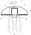
- FIG. 1 and Fig. 2 Another embodiment of the electrode is represented by an embodiment with a conductive magnet.
- This example of a geometrical arrangement of active components is shown in Fig. 1 and Fig. 2 , wherein it includes a diamagnetic wedge 10 , the main magnet 11 , and the pole piece 4 .
- These components provide increased penetration depth of the electric current flowing between the diamagnetic wedge 10 and the passive conductive contact 12 , even at low stimulation currents. They are, due to their configuration, capable of linearizing and concentrating parabolic electric field lines in an axial direction around the axis of the main magnet 11 . This results in an ion channel, limited in the diameter and direction of ion movement by the magnetic field.
- the diamagnetic wedge 10 has two functions. It diverts magnetic field lines from the axis of the main magnet 11 and provides electrical connection with the skin.
- the diamagnetic wedge 10 is made of copper and is in the shape of a cylinder, which is rounded at the end adjacent to the tissue for better contact with the skin and for maximum possible patient comfort.
- the diamagnetic wedge 10 is positioned so that it is completely or at least substantially surrounded by the magnetic field of the main magnet 11. In order to perform its function while being easy to maintain, it is further covered with a layer of gold or other non-toxic and inert material conducting electricity well.
- the outer casing and the base of the main magnet 11 away from the skin are preferably surrounded by the pole piece 4 made of diamagnetic material.
- the diamagnetic wedge 10 on the side away from the skin is connected to the main magnet 11 by means of a conductive adhesive or other conductive connection, and, in addition to the above effects, it also prevents a so-called magnetic short circuit on the side of the main magnet 11 oriented towards the skin.
- the passive conductive contact 12 of the electrode is embodied as a thin copper sheet, which can be gold plated but other diamagnetic materials such as silver, gold, bismuth, carbon and electrically conductive plastics of various compositions can be used as well.
- the passive conductive contact 12 of the electrode is annulus-shaped and is attached to the fixing element 5, thereby being separated from the main magnet 11 by a gap filled with the same insulating material of which the fixing element 5 is made.
- the passive conductive contact 12 can be represented by various types of conductive fabrics or any conductive gel or other conductive material commonly used in medicine.
- the main magnet 11 is represented by a neodymium magnet (NdFeB).
- the main magnet 11 consists of one or, in alternative embodiments, of several adjacently arranged magnets, and it is oriented with its north pole facing the tissue.
- the fixing element 5 and the passive conductive contact 12 of the electrode are made of materials intended for medical use, which are preferably waterproof and resistant to frequent sterilization.
- Fig. 3 shows the field lines of the electrostimulation device.
- a source 9 of voltage is connected to the device between the diamagnetic wedge 10 and the passive conductive contact 12. Its output values of the signal shape and frequency are adjustable. Preferably, frequencies between 0.1 to 100 Hz can be used, and the pulse can be monophasic or biphasic. Pulse shape can be rectangular, sinusoidal or triangular with exponential inclines or declines and the pulse widths from 0.1 to 5 ms or precisely from 1 to 3 ms with an amplitude from 0 to 50 mA. A frequency between 1 to 15 Hz or, more precisely, 2 - 7 Hz appears to be the most preferred and very efficient, but each patient may respond optimally to a different frequency, so individual adjustment plays an important role.
- Another example is a solution of electrostimulation device which does not contain a diamagnetic wedge 10, and is thus suitable also for other applications, in addition to those described above, such as for stimulating superficial nerves, improving the absorption of substances through the skin, and for a better supply of nutrients to the skin.
- this embodiment sees the base of the main magnet 11 as being in direct contact with the skin. While in the embodiment illustrated in the figures, on the side facing the skin, i.e. on the side intended to be applied to the skin, the main magnet 11 is adapted for non-invasive electrical connection to the tissue by being equipped with a diamagnetic wedge 10. In this embodiment, the main magnet 11 is, on the side facing the skin, i.e.
- the fixing element can be made of plastic, rubber, or other material such as a neoprene strap or disposable tape, both of which being glued together or otherwise attached.
- the device is not intended for the treatment of stress incontinence but rather for the treatment of urgent types of incontinence or an overactive bladder (OAB), for example caused by hypersensitivity in nerve receptors in the bladder. Due to a malfunction in these receptors, even when the bladder is one-quarter full, the receptors in the brain will send a false signal leading to an urgent bladder contraction. The patient then feels an immediate need to go to the toilet or, in some cases, urine will leak.
- the purpose of stimulation using the proposed device is the transmission of signals through afferent paths to the brain, which will then restart the receptors in the bladder and these will then return to a normal state.
- the electrode 15 system and the detector 14 are connected via the control unit 13, which controls the entire system.
- the system can include a single electrode 15, or more electrodes 15. These can include transcutaneous, percutaneous, or implantable electrodes. Even when using a single electrode 15, it is possible to determine the optimal frequency; however, for clinically effective stimulation of the peripheral nerves, it is necessary to use two electrodes.
- the electrode 15 is connected to the pulse generator 18. The latter can be of two types.
- the generator 18 is either directly a part of the electrode 15, i.e. it is located within the electrode 15, or it is external.
- An external pulse generator 18 can be located in the controller 16 or, in case of implantable electrodes 15, it remotely powers the stimulator.
- the detector 14 consists of a sensor 17.
- the sensor 17 is an optical sensor 17.
- the optical sensor 17 can have several embodiments, but most preferably it is an optical barrier.
- An optical sensor 17 assembly is shown in detail in Fig. 6 and is described below in the description of the invention.
- the optical barrier includes a transmitter and a receiver.
- the transmitter includes a generator 18, an amplifier 19 and an infrared diode 20 with the optics.
- the generator 18 is set to a frequency of 38 kHz.
- the receiver includes a diaphragm 21, a converging lens 22, an infrared filter 23, a preamplifier 24, a frequency filter 25, a demodulator 26, a level converter 27 and a programmable retarder 28.
- the frequency filter 25 is set to 38 kHz.
- the following parts can be implemented as one component: converging lens 22 , infrared filter 23, preamplifier 24, filter 25 and frequency demodulator 26.
- the foot 31 is located between the transmitter output and the receiver input.
- Other types of optical barriers, such as a reflection optical barrier are not excluded by the invention.
- the optical sensor 17 can consist of one sensor 17 or more optical sensors 17 variously spaced on the detector 14. Each optical sensor 17 of the reflection optical barrier is a transmitter and a receiver at the same time. This makes it possible to detect an object, which gets into the vicinity of said sensor 17.
- the first advantage of an embodiment with multiple optical sensors 17 is that the detector 14 does not need to be set up by the operator as precisely for the patient as when using only one sensor 17. Another advantage is that more detailed information regarding movement is received from several sensors 17, which can be further processed by the control unit 13 in detail.
- the use of an optical sensor 17 is advantageous in terms of simplicity of use because the sensor 17 detects objects with good accuracy even when the distance from the sensor 17 can vary each time by a few centimeters.
- These optical sensors 17 are based on the transmission of light in the infrared or other spectrum.
- the sensors 17 may also be supplemented with a polarizing filter.
- a camera can also be used as an optical sensor 17.
- the camera may include a CCD or CMOS camera with sufficient resolution.
- the optical sensors 17 can be configured to function without modulation of the signal, with modulation of the signal for increased resistance to overloading the optical barrier by ambient light, or in the infrared region with modulation of signal for increased resistance to overloading the optical barrier by ambient light.
- the sensors 17 can be arranged one after another.
- the sensors 17 are placed on the holder, via which they are firmly attached to the rest of the structure.
- the holder with the sensors 17 can be adjusted by means of a tightening or locking element. Then the whole system records the movements of the lower limbs, which are in its vicinity.
- the sensor 17 is used as an accelerometer, which is attached to the patient's body.
- the use of an accelerometer is more user-friendly than other sensors.
- the accelerometer can be attached to the patient's body using a band to which the accelerometer can possibly be incorporated into. Further, the accelerometer is capable of detecting small changes in position.
- the accelerometer is attached to a part of the leg and the movements resulting from the stimulation are measured by the accelerometer.
- capacitive, inductive, thermal, magnetic or ultrasonic sensors 17, direct use of an electromyograph may be used. The disadvantage, compared to optical sensors 17, is the smaller distance at which the sensor 17 can detect an object.
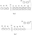
- An example of an ultrasonic sensor 17 is shown in Fig. 7 .
- Such a sensor 17 includes a generator 18 of 50 kHz, an exciter 29, a primary piezo element 30 and a secondary piezo element 32 at a resonance frequency of 50 kHz, an amplifier 33, a frequency filter 34 of 50 kHz, a demodulator 26, a level converter 27 and a programmable retarder 28.
- the limb 31 is located between the first and the second piezo elements.
- the advantage of the sensor 17 providing a digital signal is also that the analog sensors 17 can record the movements induced by the device only via a contact.
- the contact sensors 17 do not provide a high-quality information, because they naturally interfere with the observed phenomenon. In some cases it results in an echo within the sensor 17 caused by multiple recording of the same movement. Ultimately, this leads to poor detection quality and errant determination of improper frequency stimulation, or a different characteristic of voltage for stimulation.
- mechanical sensors 17 also need additional components to provide a clear, noise-free signal.
- the contactless sensors 17 or the accelerometer can be used without any modification between patients.
- the measurement when measuring the induced spasmodic movement of the feet, the measurement must be individually customized to the patient. The feet and physiology of the movements are different for each patient.
- analog sensors 17 When using analog sensors 17, such customization is performed mostly by mechanical/manual re-setting of the sensor 17. This requires technical skill on the part of the operator, usually a doctor. As a result, treatment duration and risk of incorrect recording by the sensor 17 are increased.
- the sensor 17 is capable of sending the information related to frequency and preferably also other information related to the patient's body motion, such as range of motion or speed. Misuse of the sensors 17, usually contact sensors, as well as directly switching the stimulation of the patient, constitute a significant risk and, due to their error rates, do not result in proper therapy. They do not provide any information about frequency or other parameters, such as range of motion or speed, but they directly affect the activity of the electrode 15. If the system is operating with information on the frequency of movement of a part of the patient's body, it can be software-configured to various configurations and can process the information differently. This, inter alia, also provides other advantages, which are described further below.
- control unit 13 In order to send the information on movement frequency, the control unit 13 must be provided with digital information.
- digital information can be realized in two ways. Either when the direct output from the sensor is 17 is digital, or when the analog output must be connected to the A/D converter, which converts the analog signal to a digital one and sends it on to the control unit 13.
- the sensor 17 for detecting movement of the stimulated limb sends the information to the control unit 13.
- the control unit 13 uses the information to directly control the electrodes 15 attached to the patient as feedback for effective neuromodulation of peripheral nerves.
- the induced movements of the legs provide clinical information that the set frequency of stimulation current is correct.
- the control unit 13 is guided to read the frequency spectrum between the preset limit values. These values are already factory-set, and they are 1 Hz and 100 Hz.
- the control unit 13 controls the electrodes 15 in two phases. These phases are the recognition phase and the therapeutic phase. In the recognition phase, the device of the invention searches for an ideal frequency or other parameters of the course of current for the individual patient based on the feedback from the sensor 17.
- the control unit 13 system includes the set rules, defining at what point the frequency of neuromodulation is considered optimum for the patient. Ideally, it is possible to detect each stimulus as a twitch. If the control unit 13 recognizes the ideal frequency, it is switched to a therapeutic regime. In this mode, the control unit 13 maintains the detected frequency, thus leading to stimulation of the peripheral nerves without further changes. This phase can typically take 30 minutes. In some cases, for sufficient efficiency of the clinical procedure, this may take only about two minutes.
- the control unit 13 can be set to include such a condition that once the ideal positive feedback linkage from the sensors 17 disappears, the control unit 13 is switched back to the first recognition phase, and it sets the neighboring frequencies to initially identified frequencies.
- control unit 13 sets other parameters of the pulse as well. One of them is the pulse length, which is between 0.1 and 10 ms. Another factor controlled by the control unit 13 is pulse shape.
- the control unit 13 also sets the voltage polarity ranging from positive to negative. Unlike the approach of stimulation by DC, the biphasic current does not cause electrolysis of tissue, and electrolysis presents a problem for sensitive patients, as it potentially leads to skin problems (irritation of skin, infection).
- the control unit 13 is set in such a way that it calculates the optimum flow of the pulse current x with opposite polarity in order to cancel the effect of electrolysis. This mechanism is also known under the term "charge-balanced pulse". This feature makes the device safer.
- control unit 13 sets the flow of pulse rounds or pulse bursts. This is, for example, 20 pulses applied over a very short time. In terms of a longer time interval, these pulse bursts appear as a single pulse of an irregular shape.
- control unit 13 commanding these parameters is required.
- the control unit 13 uses the information from the controller 16 and the information on frequency of limb movement from the sensor 17.
- the control unit 13 includes a memory unit where the staff can store data for a single patient, including information relating to at least one identified ideal parameter for a given patient.
- the memory of the present invention can be any kind of data storage, either a local or remote one. These storage devices include HDD and SSD hard drives, flash memories, memory cards, RAM devices, CDs, DVDs, Blu-rayTM discs, etc.
- the remote storage units include the ones that are accessible only by connecting the device to a local network or the internet, GSM, such as cloud storage.
- GSM Global System for Mobile communications
- Local network, internet or GSM can all be understood as a network service.
- the network may by created also by a number of presented neuromodulation devices, wherein the first of the neuromodulation devices is connected to remote storage, and the others are connected to this neuromodulation device.
- the indirect connection of other neuromodulation devices connected to the remote storage is preferably wireless.
- the other neuromodulation devices communicate with the remote storage unit through the first neuromodulation device.
- the first neuromodulation device redirects the data from the remote storage unit to the other neuromodulation devices connected to the first neuromodulation device as per the identification part of the communicated data.
- the stored information about the patient effectively reduces the time required for performing the procedure, and it can also serve as additional home therapy.
- the patient has can buy the electrodes 15 intended for domestic use for themselves, allowing the patient or a family member to apply them.
- This type of device also has a control unit 13 which can use the stored information on the identified stimulation parameter and adjust the therapy accordingly.
- the entry of this information to the device depends on the selected storage method, which is not particularly limited by the invention. In a preferred embodiment, it can be, for example, an SD memory card which is inserted into the device in the doctor's office to identify the ideal stimulation parameter and also into the device for home use, where the proper therapeutic settings are as per the identified stimulation parameter.
- the selected storage device can be e.g. cloud memory.
- the stimulation parameter can be entered through the device to the cloud storage and made accessible at the doctor's office or in home therapy by the same or any other device.
- the cloud storage and the stimulation parameter entered thereto may also be accessible through a computer, tablet, mobile phone or other electronic device connected to cloud storage.
- storing patient data has other advantages. Thanks to the determination of individual stimulation parameters, there is no need to store this information in another patient file. On the patient's next visit, it is only necessary to recall the information automatically from the system with no search being necessary. This also prevents a possible error arising from poor handwriting. An incorrectly set parameter does not lead to improvement of the patient's condition.
- the system comprising such information can be further enhanced by including the statistics that are directly related to the use of the device. In addition to information on a particular frequency, the system stores other parameters affecting the pulses described above, such as the polarity of pulses, their length, shape, and others. These statistics are also saved to memory where the therapeutic information is available for a particular patient.
- the amount invoiced to the patient is always determined correctly and fairly.
- these statistics are useful for determining the usability of the device, calculating the avoided costs associated with alternative treatments, calculating service intervals, and so on.
- the control unit 13 can be a single control unit, or the device can include several control units 13, e.g., one for the detector 14 and another for controlling the electrodes 15. If the device involves several control units 13, these units are equipped with communication protocols for continuous information exchange. As a part of the therapeutic device, the control unit 13 also serves as a decision-making actor instead of the doctor. In analogue systems, it was necessary that the doctor directly set the parameters depending on the observation of induced movements or depending on the sensor 17 output for same. This leads to lower therapeutic efficiency.
- the advantage of sending the movement frequency information from the sensor 17 to the control electronics is increasing the safety and efficiency of the product.
- mechanical sensors 17 connected to the electronics which use only the amplified signal from the sensor 17 as an excitation signal for stimulation, a potentially dangerous situation can arise. Due to higher requirements for medical devices, such an approach is not feasible in clinical conditions; therefore, a device must comprise a control unit 13 with included commands for various situations, thus ensuring an increased security. These commands can be a part of the software or firmware of the control unit 13 depending on its technical level.
- the mechanical sensors 17 are also prone to error conditions. They represent a high risk, specifically in cases in which the recording is used as input for stimulation by the electric current.
- the device also involves a controller 16.
- the controller 16 represents user input for controlling the control unit 13, and this input can take various shapes and forms.
- the controller 16 comprises the control unit 13 described above. In alternative embodiments, the control unit 13 is outside the controller 16.
- the controller 16 is part of the structure of the entire device but does not need to be fixed firmly.
- the controller 16 can be loosely attached to the structure, but it can be lockable with respect to the support structure in at least one position.
- the controller 16 involves a display device and a button.
- the button connected to the controller 16 can be a multistep one, enabling more than one instruction to be given depending on the movement of the controller 16 chosen by the operator.
- the display device is used for transferring the information to the operator.
- the display device can show the instructions for using the device, so that the therapy is as effective as possible. These can be in the form of a sequence of instructions that are shown on the display device one by one by the operator's clicking on the button of the controller 16. The displayed information is controlled by the control unit 13 of the device.
- Symptoms of an overactive bladder are, according to the present invention, treated using a neuromodulation device comprising at least two active electrodes capable of generating electrical pulses.
- the first step of the present invention is attaching first one active electrode to a patient's leg and attaching a second active electrode to any of the patient's legs.
- Attaching of any of the active electrodes is to be understood as attaching a removable electrode to the patient's skin (transcutaneous) or attaching any of the active electrodes to the patient's body by penetrating the patient's skin percutaneously or attaching any of the active electrodes by implanting the active electrodes into the patient's leg for long-term implantation.
- the first electrical pulses are generated in the first active electrode into the patient's body and the second electrical pulses are generated in the second active electrode into the patient's body.
- the present invention involves a step of setting a flow of the current of the pulses.
- the present invention further includes a step of synchronizing the timing of each pulse.
- the pulses are delivered to the branches of the patient's nerves, thus stimulating the nerves and delivering the stimulus in the form of the pulse to the target area.
- the target area is the sacral plexus or the sciatic nerve.
- the first electrical and second electrical pulses are generated in turns, thus the interval of the electrical pulses can be as follows: the first electrical pulse, then the second electrical pulse, then the first electrical pulse, and so on.
- the interval can be as follows: the second electrical pulse, the first electrical pulse, the second electrical pulse and so on.
- the electrical pulses can be generated simultaneously at the same time or can be generated independently, such as the first electrical pulse, the second electrical pulse, the first electrical pulse, and so on.
- a third active electrode is attached to the patient's body, for example, a third active electrode capable of generating electrical pulses is attached to either of the patient's legs.
- the third electrode generates the third electrical pulses, which are synchronized so that one of the third electrical pulses, one of the second electrical pulses and one of the first electrical pulses reach the target area simultaneously.
- more active electrodes can be attached to the patient's body in order to generate electrical pulses.
- the active electrode is an electrode such as the electrode described previously and illustrated in Fig. 4 , comprising a magnet 3, a pole piece 4, the first pole 1 of the electrode and the second pole 8 of the electrode.
- Another embodiment of the electrode is the electrode shown in Figure 1 . and described previously.
- the electrodes used are transcutaneous as in the two electrodes described previously or another embodiments of transcutaneous electrodes. Transcutaneous electrodes are advantageous mostly because their usage does not require invasive procedures.
- the percutaneous electrodes capable of penetrating the patient's skin and capable of generating electrical pulses are used as active electrodes.
- the electrodes are long-term implantation electrodes.
- the electrodes for example, the first electrode, the second electrode and the other electrodes can involve one or more conductors.
- the active electrodes of any type are characterized in that they are capable of generating electrical pulses or capable of delivering the electrical pulses generated by a pulse generator to the body of the patient.
- the generator is either directly a part of the electrode, i.e. it is located within the electrode, or it is external.
- An external pulse generator can be located in the controller or, in case of implantable electrodes, it remotely powers the stimulator.
- the electrodes can be inductively "charged".
- the external pulse generator is connected to an inductor, and the electrical pulses are generated in the electrodes by the magnetic field created by the inductor.
- the active electrodes are attached in proximity to the branches of a peripheral nerve so that the electrical pulses generated by any of the electrodes are capable of delivering electrical pulses to the nerve.
- the electrodes are placed, for example, in the area of the knee so that the surface of the electrodes is facing a branch of peripheral nerve through the tissue.
- the electrodes are placed within the vicinity of the branches of a peripheral nerve while not directly touching the branches of a peripheral nerve.
- any of the following nerves are stimulated: the lumbosacral plexus, sciatic nerve, common peroneal, tibial nerve, pudendal nerve, superior gluteal nerve, inferior gluteal nerve, posterior cutaneous femoral nerve, obturator internus nerve, piriformis, quadratus femoris nerve, plantar nerve or coccygeal nerve.
- Most advantageous in treatment of the symptoms of an overactive bladder is stimulation of the peroneal nerve, pudendal nerve, tibial nerve or any combination of the aforementioned nerves.
- Stimulation of the nerves is achieved by sending the electrical pulses through the branches of peripheral nerves and distributing the nerve stimulus to the target area of, for example, other sacral plexus or the sciatic nerve.
- the electrodes can be, as per the present invention, attached to the patient so that the first active electrode is attached to the first branch of a sciatic nerve and the second active electrode is attached to a second branch of the sciatic nerve; in other embodiments, multiple active electrodes can be attached to multiple branches of the sciatic or other nerves in order to stimulate the target area.
- the active electrodes can be both attached to the same leg or be each attached to a different leg of the patient. In some cases, attaching the active electrodes to different legs of the patient increases the healing effect, as the simultaneous effect of stimulation is more easily achievable.
- grounding conductor placed on the patient's body.
- the grounding conductor is in the form of a pad.
- the grounding pad can be placed anywhere on the patient's body.
- the grounding conductor is placed on the patient's suprapubic, hypogastric or sacral area. By placing the grounding conductor in said areas, the healing effect of the method increases. For the grounding conductor attracts the first and second electrical pulses, thus the target area is reached more effectively.
- the grounding conductor can be configured for generating the electrical pulses, wherein in some embodiments, the grounding conductor generates positive electrical pulses and thus has a calming effect on the patient's bladder.
- a variety of electrical pulses may be used. In a preferred embodiment, the following limitations may be used for the electrical pulses.
- the frequency of the first electrical pulses, second electrical pulses or, in some embodiments, the pulses generated by a third, a fourth or other electrodes is between 0.1 Hz and 100 Hz.
- Pulse width of said pulses is between 0.1 ms and 5 ms, and the current of said pulses is between 0 mA and 250 mA, with the voltage of said pulses being between 0 V and 90 V.
- the parameters of pulses therefore vary for individual patients. In one of the preferred embodiments, the parameters vary over the course of the treatment of the patient according to the patient's response to the treatment.
- Adjustment of the parameters can be made by the person providing the treatment or automatically by means of a control unit having a suitable algorithm.
- the best treatment results are achieved by using the following parameters of said pulses: a voltage frequency of between 2.5 Hz and 60 Hz and a pulse width between 0.1 ms and 2.5 ms.
- the Current of said electrical pulses also depends on the type of the electrode used and its surface. Using electrodes which have an active surface of more than 2 cm 2 achieves the most effective treatment results using a current of the said electrical pulses between 15 mA and 250 mA. Using electrodes which have an active surface of between 0.5 cm 2 and 2 cm 2 achieves the most effective treatment results using a current of said pulses between 0 mA and 15 mA.
- an advantageous embodiment should have the shapes of said electrical pulses as substantially rectangular or substantially of the shape of right triangle. Said pulses are monophasic or biphasic.
- a biofeedback signal can be visual or determined means of a sensor.
- the biofeedback can be the form of twitching in the patient's lower limb.
- said pulses are applied to the patient's body in a synchronized manner so that nerve stimuli generated in the patient's nervous system by the first electrical pulses and the nerve stimuli generated in the patient's body by the second electrical pulses reach the target area simultaneously so that the nerve stimulus generated in the patient's nervous system by any of the first electrical pulses and the nerve stimulus generated in the patient's nervous system by any of the second electrical pulses reach the target area at the same time.
- nerve stimuluses are also generated in the patient's nervous system by tertiary electrical pulses and/or by any further electrical pulses generated by any other active electrodes, which are synchronized.
- Synchronization of the pulses provides more effective treatment, so that quicker recovery and shorter treatment sessions are preferably achieved.
- Synchronization of the pulses can be, according to one of the present embodiments, achieved by means of an algorithm stored in the memory of the control unit, wherein the algorithm sets the timing of the generation of the electrical pulses. Multiple inputs can be acquired by the algorithm, such as data from a sensor monitoring biofeedback, duration, and parameters of the first electrical pulses, second electrical pulses and any other electrical pulses, data of the previous treatment sessions of the patient and other relevant data.
- a method of positioning the electrodes is further disclosed, wherein, firstly, an active electrode is attached to the patient's body. Preferably but not exclusively, the attachment is made in the knee area of the patient. After the attachment, electrical pulses are generated in the active electrode. After and/or during the generation of these electrical pulses, the reflex movement of the patient's body part is monitored.
- the reflex movements of the patient's body part are, for example, twitches of the lower limb, and such monitoring can be done either visually or by sensor.
- the monitored reflex movement such as the twitching of the patient's lower limb, is thereafter, or during the monitoring, compared to the expected reflex movement. Determination can be made by the person or by an algorithm.
- the algorithm compares the data acquired by the sensor and compares it to the data stored in the memory of the control unit.
- data can be represented by the number of twitches of the limb per period of time.
- the control unit can visually, acoustically or tactually inform the person of the achievement of sufficient or insufficient reflex movement of the patient's body part. If the reflex movement of at least part of the patient's body is insufficient, the electrode is relocated on the patient's body and the steps are repeated.
- This method enables the user to precisely position the active electrode in order to stimulate the nerves of the patient more effectively.
- the method described above is also suitable for treatment of other medical conditions, such as and not limited to, painful bladder syndrome, fecal incontinence or Low Urinary Tract Dysfunction.
- the active electrode is of a transcutaneous type and the neuromodulation device involves two active electrodes, a grounding electrode, a memory unit, a control unit, a sensor for monitoring the reflex movement of at least a part of the patient's body, such as an accelerometer communicatively coupled to the control unit, and a controller for controlling the neuromodulation device.
- a person such as the patient or the patient's physician, attaches the active electrode onto the patient's body.
- the person attaches the first electrode, for example, in the knee area of the first leg in such manner that the first electrode's active surface faces approximately the peripheral nerve.
- the person further places the grounding electrode, preferably in the form of a pad, on patient's suprapubic, hypogastric or sacral area.
- the person further places the accelerometer on the patient's leg.
- the then person activates the device to start generating the first electrical pulses.
- the neuromodulation device informs the patient of the sufficiency of the induced movements of the part of the patient's body, in this embodiment, the leg.
- the initial pulses are generated with parameters according to the previous treatment sessions of the patient; in cases in which the parameters are not stored in memory, the control unit sets the parameters based on pre-set default parameters.
- the parameters of the first electrical pulses are any of the following frequency intervals: between 0.1 Hz and 100 Hz, a pulse width of between 0.1 ms and 5 ms, a current of between 0 mA and 250 mA, with a voltage between 0 V and 90 V.
- the control unit generates the first electrical pulses and changes the parameters of the pulses.
- the device informs the person, for example, audibly or visually in another manner. For example, by means of a red light, a text display or by means of a predefined sound.
- the neuromodulation device informs the person of sufficient reflex movement either audibly or visually, for example, by means of, say, a green light or by a text display.
- the second active electrode is attached to the patient's second leg in the knee area in the same way as the first electrode.
- the second electrode is further precisely positioned using substantially the same steps as in the foregoing precise positioning of the first active electrode.
- the first electrical pulses and the second electrical pulses are directed to the patient's body, stimulating the target area.
- the flow of the pulse current is set manually or by means of the control unit.
- the parameters of the first electrical pulses and the second electrical pulses are set via the control unit.
- the synchronization of the pulses is achieved by means of the control unit, for example, on the basis of biofeedback, such as the reflex movement of the patient's leg.
- the parameters of the pulses might vary during the treatment session, depending upon the patient's biofeedback. The treatment session takes typically 15 to 45 minutes.
Landscapes
- Health & Medical Sciences (AREA)
- Life Sciences & Earth Sciences (AREA)
- Engineering & Computer Science (AREA)
- Public Health (AREA)
- General Health & Medical Sciences (AREA)
- Animal Behavior & Ethology (AREA)
- Biomedical Technology (AREA)
- Veterinary Medicine (AREA)
- Biophysics (AREA)
- Radiology & Medical Imaging (AREA)
- Nuclear Medicine, Radiotherapy & Molecular Imaging (AREA)
- Heart & Thoracic Surgery (AREA)
- Physiology (AREA)
- Medical Informatics (AREA)
- Molecular Biology (AREA)
- Physics & Mathematics (AREA)
- Pathology (AREA)
- Surgery (AREA)
- Neurology (AREA)
- Gastroenterology & Hepatology (AREA)
- Neurosurgery (AREA)
- Urology & Nephrology (AREA)
- Transportation (AREA)
- Mechanical Engineering (AREA)
- Electrotherapy Devices (AREA)
- Epidemiology (AREA)
- Primary Health Care (AREA)
- Physical Education & Sports Medicine (AREA)
- Magnetic Treatment Devices (AREA)
Description
- The invention relates to a neuromodulation device for the stimulation of neurons in the patient's body by means of an electric current having the parameters that are most suitable for treatment of a particular disease and person and which are set on the basis of the patient's bodily feedback.
- The use of electrical stimulation of neurons in favor of to benefit a human subject is described for example, in
US 13704337 US 7257448 ,WO 2014/113813 A1 ,US 2009/306531 A1 ,WO 2012/106548 A2 ,US 2016/121109 A1 orWO 2008/062395 A1 and is used to treat incontinence, to stimulate muscles for the purpose of simulating exercise and subsequent increase of heart rate, to improve lymphatic drainage of the lower limbs, to stimulate neurons, and for other related applications associated with the positive effects of electric current. - The percutaneous tibial nerve stimulation (PTNS) method for treating incontinence uses a needle introduced in close proximity of the nerve in the ankle region, and by means of an electric current connected thereto, it stimulates that nerve as well as the adjacent nerves in the pelvic area. This repeated stimulation of the pelvic region can have a significantly positive effect on both the functioning of muscles and the communication between the patient's body and nervous system. Improvement of bladder function by stimulation using electrical current is achieved by repeated sessions lasting several minutes. The historic disadvantages of inserting needles into the patient's body include mainly pain, the risk of nerve damage, and also the requirement of a medical professional to carry out the treatment. For a successful treatment, it is important to ensure accurate targeting of the nerves to be stimulated. In practice, the subjective feeling of the patient is used, and most importantly, the plantar flexion caused by nerve stimulation is observed. However, this is not always accurate, and it has proven to be the biggest obstacle in achieving the best success rates.
- A device measuring the response to nerve stimulation is described in the patent No.
WO 2015/066597 . Two small perianal electrodes described therein, however, are undoubtedly a difficult solution to be implemented without the presence of a trained medical personnel. This device receives a signal from digital input and stores at least a part of the signal in memory. Thus, it keeps a record of the current procedure being performed via a sensor module, and initiates transmission of at least a part of the record to or from the sensor module by means of the communication device in real time in order to determine whether the desired stimulation (compound motor action potential) is being achieved. - An example of a detector for touch reading the reflexive movements of muscular groups and generating an electrical signal for feedback control of the impulse stimulation frequency in the resonance regime is described in patent No.
WO 2013/113297 . - An electromyogram device for detection of the patient's body signals is described in documents Nos.
US 20150126894 ,US5800470 , and document No.WO 2005023087 provides an improvement on the electromyogram device. - Until now, such devices required professional application and setting of electric current parameters on the basis of the patient's verbal assessment or observations. Conversely, it can be set at a preset average value for all patients, though this is not suitable for everyone. For example, patients with abnormalities such as high body weight or high skin resistance would see inadequate results from the treatment. Therefore, there is a need for adapting electrical quantities to individual needs. This problem is solved by the system and method for setting its parameters described below.
- Further, the above-described methods tend to show lower treatment efficacy. Application of nerve stimulation is made solely by one active electrode per nerve branch of the sciatic nerve or per limb. Such treatment methods prolong treatment time and requires a large number of treatment sessions, thus inconveniencing both the patients and/or the medical staff.
- The present invention provides a neuromodulation device for stimulating peripheral nerves as defined by the
independent claim 1. Preferred embodiments are defined in the appended dependent claims. Aspects, embodiments and examples disclosed herein which do not fall within the scope of the appended claims do not form part of the invention, and are merely provided for illustrative purposes. - In one aspect the present invention provides a device for stimulating the peripheral nerves, comprising a memory unit, at least one electrode attached to the patient's body for generating pulses, a control unit connected to the electrode for setting at least one electrode pulse parameter, and further connected to at least one response detector to neuromodulation. The response detector to neuromodulation is connected to a control unit for transmitting information on the frequency of movement of at least a part of the patient's body. The control unit of the device further sets the flow of current of electrode pulses automatically, depending on information about the frequency value of movement of at least a part of the patient's body. The control unit may receive information on the frequency value from the response detector to neuromodulation, or from memory. The detector of the device may be an optical sensor, an infrared sensor, an accelerometer, or a capacitive, inductive, thermal, flow, ultrasound, or magnetic sensor. In an alternative embodiment of the invention, an electromyograph can also be used as a detector. In a preferred configuration, the detector can make use of more than one sensor.
- The control unit may change the frequency of the electrode pulses until it substantially equals the frequency of the recorded movements. The control unit may also change the flow of the current of pulses until the optimum frequency of recorded movement is reached.
- The device may include one or more control units, which are separated. The control unit can be a part of the controller, which may further comprise a display device and user input for the operator. The control unit may set the frequency of the pulses in a range between 0.1 and 100 Hz and may set the length of the pulses in a range between 0.1 and 10 ms. The control unit, as per the present invention, may further set the shape of the pulse. The control unit of the present device may further set the polarity of the voltage ranging from positive to negative.
- The control unit may communicate with a database stored in the memory, which is the internal memory of the control unit, or in a remote storage unit, available via network services. Here it may store the information on recommended parameters of the flow of the current of pulses. The database may further include the patient's personal data, such as but not limited to: information on the patient's age, sex, information on identity and personal data of the patient, for example identification number, number of the insurance, address, social security number, credit card number and so on.
- The control unit may send the information from the database to the remote storage. The neuromodulation device may involve a control unit and at least two active electrodes. The active electrodes may be attached to the patient's body, so that the first active electrode is attached to either of the patient's legs and the second active electrode is also attached to either of the patient's legs. After the active electrodes are attached, the first electrical pulses in the first active electrode may be delivered to the patient's body, and at the same time or subsequently, other electrical pulses in the second active electrode may be delivered to the patient's body and the flow of the pulse current may be set. The preferred method further involves a step of synchronizing the timing of each pulse.
- The active electrodes may be attached in the proximity of branches of a peripheral nerve. The active electrodes may be attached to the patient so that the first active electrode is attached to the first branch of the sciatic nerve and another, second, active electrode is attached to another branch of the sciatic nerve. One of the following nerves may be stimulated: the lumbosacral plexus, sciatic nerve, common peroneal nerve, tibial nerve, pudendal nerve, superior gluteal nerve, inferior gluteal nerve, posterior cutaneous femoral nerve, obturator internus nerve, piriformis, quadratus femoris nerve, plantar nerve, coccygeal nerve. In preferred embodiment, pudendal nerve or tibial nerve or common peroneal.
- The first active electrode may be attached to one leg of the patient and the second active electrode may be attached to the other leg of the patient. Alternatively, the first active electrode may be attached to the first leg of the patient and the second active electrode attached to the same leg. The first active electrode may be attached to the back of either knee and the second active electrode may be attached to the back of the other knee. Synchronization of the electrical pulses may be achieved by timing the pulses by to the beginning of each pulse. Timing of pulses may be synchronized as per the time of delivery of the pulse from the first active electrode and the time of delivery of the pulse from the other active electrode in the target area. A grounding connector may be placed on the patient's body, most advantageously on the patient's suprapubic, hypogastric or sacral area.
-
-
Fig. 1 shows an illustrative example of the electrode. -
Fig. 2 shows the same view from below. -
Fig. 3 shows an illustrative example the radiation emitted by the electrode. -
Fig. 4 shows an alternative illustrative embodiment of the electrode. -
Fig. 5 shows an illustrative example of the neuromodulation device. -
Fig. 6 shows the illustrative example of an assembly of the optical sensor in the detector. -
Fig. 7 shows an illustrative example of an assembly of the ultrasonic sensor in the detector. - One example of the neuromodulation device includes three major components, as shown in
Fig. 5 . The first component is acontrol unit 13, the second one is adetector 14, and the third is anelectrode 15. The electrode can be of two types. The first possible embodiment of the electrode is the one shown inFig. 4 , which involves amagnet 3, apole piece 4, thefirst pole 1 of the electrode and thesecond pole 8 of the electrode. The role of themagnet 3 is to increase the depth range at low stimulation currents. Together with thepole piece 4, it can linearize and concentrate parabolic electric field lines in an axial direction around the axis of thefirst pole 1 of the electrode. This substantially results in a tunnel effect for direction of movement and concentration of ions as carriers of electrical charges into the intercellular spaces. In this embodiment, themagnet 3 is permanent and has the shape of a hollow cylinder, with thefirst pole 1 of the electrode, for example of copper or brass, passing through its center. In the area of contact with the skin, thefirst pole 1 of the electrode is preferably round and coated with a layer of a suitable material, such as silver. The outer casing and the side of thepermanent magnet 3 away from the skin are surrounded by thepole piece 4 of diamagnetic material. From the side away from the skin, thefirst pole 1 of the electrode is threaded for affixing anut 6 and terminates with anadapter 7 for connecting thewire 2. Alternatively, thefirst pole 1 of the electrode is fixed in combination with a spring and the additional bottom part. Thefirst pole 1 of the electrode is unthreaded and has a stop edge matching at least a part of the additional bottom part, wherein thefirst pole 1 of the electrode is fixed by a biasing spring member so that the spring member creates a tension between thefirst pole 1 of the electrode and, directly or indirectly, the fixingelement 5 . Thus force is applied in between the stop edge of thefirst pole 1 of the electrode and at least a part of the additional bottom part, resulting in fixing thefirst pole 1 of the electrode. The annulus-shapedsecond pole 8 of the electrode is secured to a fixingelement 5 while separated from thefirst pole 1 of the electrode by a gap or another insulator. Thus, it is a bipolar electrode having the fixed position of thefirst pole 1 of the electrode and thesecond pole 8 of the electrode. Themagnet 3 is separated from thefirst pole 1 of the electrode by an insulator and possibly also by an air gap. Themagnet 3 is oriented with its north pole facing the tissue. Thefirst pole 1 of the electrode, themagnet 3, thepole piece 4 and thesecond pole 8 of the electrode are made of materials intended for medical use, and are electrically insulated from each other, except for the area of themagnet 3 pole being in contact with the pole piece. Also, the insulation is of biocompatible material, which is also able to withstand frequent sterilization and is preferably also waterproof. - Preferably, the
magnet 3 can be in the form of an electromagnet. Using asuitable source 9, as obvious to those skilled in the art, by means of a adjustable magnetic excitation, it is possible to set the shape of the area with the highest concentration of the charge carriers, i.e. a kind of a channel. Moreover, if several electromagnets are used, by means of their different excitations, it is possible to affect the direction of electric current flow to the tissue, i.e. direction of such a channel. As an example, this can be used for finding the desired nerve, even in the event of inaccurate placement of the electrostimulation device to the skin. - The
DC source 9 is connected between thefirst pole 1 of the electrode and thesecond pole 8 of the electrode. The frequency can be set between 1 to 15 Hz and the pulses can be monophasic or biphasic, and for example, rectangular, sinusoidal or triangular, with exponential inclines or declines, and widths from 0.1 to 5 ms with a current range from 0 to 50 mA. A frequency from 2 to 6 Hz appears to be the most preferred and is very efficient. - Further included is a harness for fixing the device to a particular site and a power supply. Proper placement of electrostimulation electrodes is crucial for the efficiency of the entire method and for eliminating the risk of reduced efficiency of the method due to improper handling of the electrode. The role of the fixing
element 5 is to ensure repeated attachment of the electrodes to the same electrostimulation site. To fix the position of the electrode, a special harness is used which can use the shape of a human body as a fixation point to create a shape that is permanently adapted to the patient and ensures equal conditions for each stimulation session. - Another embodiment of the electrode is represented by an embodiment with a conductive magnet. This example of a geometrical arrangement of active components is shown in
Fig. 1 and Fig. 2 , wherein it includes adiamagnetic wedge 10 , themain magnet 11 , and thepole piece 4 . These components provide increased penetration depth of the electric current flowing between thediamagnetic wedge 10 and the passiveconductive contact 12 , even at low stimulation currents. They are, due to their configuration, capable of linearizing and concentrating parabolic electric field lines in an axial direction around the axis of themain magnet 11 . This results in an ion channel, limited in the diameter and direction of ion movement by the magnetic field. Thus, as carriers of electric charge into the intercellular spaces, the ions move along trajectories determined by magnetic field lines. Thediamagnetic wedge 10 has two functions. It diverts magnetic field lines from the axis of themain magnet 11 and provides electrical connection with the skin. In this example, thediamagnetic wedge 10 is made of copper and is in the shape of a cylinder, which is rounded at the end adjacent to the tissue for better contact with the skin and for maximum possible patient comfort. As is evident fromFig. 2 , thediamagnetic wedge 10 is positioned so that it is completely or at least substantially surrounded by the magnetic field of themain magnet 11. In order to perform its function while being easy to maintain, it is further covered with a layer of gold or other non-toxic and inert material conducting electricity well. The outer casing and the base of themain magnet 11 away from the skin are preferably surrounded by thepole piece 4 made of diamagnetic material. Thediamagnetic wedge 10 on the side away from the skin is connected to themain magnet 11 by means of a conductive adhesive or other conductive connection, and, in addition to the above effects, it also prevents a so-called magnetic short circuit on the side of themain magnet 11 oriented towards the skin. In this example, the passiveconductive contact 12 of the electrode is embodied as a thin copper sheet, which can be gold plated but other diamagnetic materials such as silver, gold, bismuth, carbon and electrically conductive plastics of various compositions can be used as well. In the figures, the passiveconductive contact 12 of the electrode is annulus-shaped and is attached to the fixingelement 5, thereby being separated from themain magnet 11 by a gap filled with the same insulating material of which the fixingelement 5 is made. In other embodiments, however, the passiveconductive contact 12 can be represented by various types of conductive fabrics or any conductive gel or other conductive material commonly used in medicine. In this example, themain magnet 11 is represented by a neodymium magnet (NdFeB). Themain magnet 11 consists of one or, in alternative embodiments, of several adjacently arranged magnets, and it is oriented with its north pole facing the tissue. The fixingelement 5 and the passiveconductive contact 12 of the electrode are made of materials intended for medical use, which are preferably waterproof and resistant to frequent sterilization.Fig. 3 shows the field lines of the electrostimulation device. - A
source 9 of voltage is connected to the device between thediamagnetic wedge 10 and the passiveconductive contact 12. Its output values of the signal shape and frequency are adjustable. Preferably, frequencies between 0.1 to 100 Hz can be used, and the pulse can be monophasic or biphasic. Pulse shape can be rectangular, sinusoidal or triangular with exponential inclines or declines and the pulse widths from 0.1 to 5 ms or precisely from 1 to 3 ms with an amplitude from 0 to 50 mA. A frequency between 1 to 15 Hz or, more precisely, 2 - 7 Hz appears to be the most preferred and very efficient, but each patient may respond optimally to a different frequency, so individual adjustment plays an important role. - Another example is a solution of electrostimulation device which does not contain a
diamagnetic wedge 10, and is thus suitable also for other applications, in addition to those described above, such as for stimulating superficial nerves, improving the absorption of substances through the skin, and for a better supply of nutrients to the skin. For non-invasive electrical connection with the tissue, this embodiment sees the base of themain magnet 11 as being in direct contact with the skin. While in the embodiment illustrated in the figures, on the side facing the skin, i.e. on the side intended to be applied to the skin, themain magnet 11 is adapted for non-invasive electrical connection to the tissue by being equipped with adiamagnetic wedge 10. In this embodiment, themain magnet 11 is, on the side facing the skin, i.e. on the side intended to be applied to the skin, adapted for non-invasive electrical connection to the tissue by being coated at least on a part of the surface with epoxy resin, conductive plastic, or metal such as nickel, silver, carbon, gold or platinum. This is again a bipolar electrode, in which themain magnet 11 and the passiveconductive contact 12 are firmly fixed in the fixingelement 5 relative to one another, which is advantageous for re-stimulation of a particular site. As with the other embodiments, it is possible to enhance the effects of the magnetic field usingpole piece 4 of themain magnet 11 as described above, but its use is not required for all applications. - The fixing element can be made of plastic, rubber, or other material such as a neoprene strap or disposable tape, both of which being glued together or otherwise attached.
- The device is not intended for the treatment of stress incontinence but rather for the treatment of urgent types of incontinence or an overactive bladder (OAB), for example caused by hypersensitivity in nerve receptors in the bladder. Due to a malfunction in these receptors, even when the bladder is one-quarter full, the receptors in the brain will send a false signal leading to an urgent bladder contraction. The patient then feels an immediate need to go to the toilet or, in some cases, urine will leak. The purpose of stimulation using the proposed device is the transmission of signals through afferent paths to the brain, which will then restart the receptors in the bladder and these will then return to a normal state.
- The
electrode 15 system and thedetector 14 are connected via thecontrol unit 13, which controls the entire system. As mentioned above, the system can include asingle electrode 15, ormore electrodes 15. These can include transcutaneous, percutaneous, or implantable electrodes. Even when using asingle electrode 15, it is possible to determine the optimal frequency; however, for clinically effective stimulation of the peripheral nerves, it is necessary to use two electrodes. Theelectrode 15 is connected to thepulse generator 18. The latter can be of two types. Thegenerator 18 is either directly a part of theelectrode 15, i.e. it is located within theelectrode 15, or it is external. Anexternal pulse generator 18 can be located in thecontroller 16 or, in case ofimplantable electrodes 15, it remotely powers the stimulator. - The
detector 14 consists of asensor 17. In one exemplary embodiment, thesensor 17 is anoptical sensor 17. Theoptical sensor 17 can have several embodiments, but most preferably it is an optical barrier. Anoptical sensor 17 assembly is shown in detail inFig. 6 and is described below in the description of the invention. In general, the optical barrier includes a transmitter and a receiver. The transmitter includes agenerator 18, anamplifier 19 and aninfrared diode 20 with the optics. Thegenerator 18 is set to a frequency of 38 kHz. The receiver includes adiaphragm 21, a converginglens 22, aninfrared filter 23, apreamplifier 24, afrequency filter 25, ademodulator 26, alevel converter 27 and aprogrammable retarder 28. Thefrequency filter 25 is set to 38 kHz. The following parts can be implemented as one component: converginglens 22 ,infrared filter 23,preamplifier 24,filter 25 andfrequency demodulator 26. In this system of transmitter and receiver, thefoot 31 is located between the transmitter output and the receiver input. Other types of optical barriers, such as a reflection optical barrier, are not excluded by the invention. When using a reflection optical barrier, theoptical sensor 17 can consist of onesensor 17 or moreoptical sensors 17 variously spaced on thedetector 14. Eachoptical sensor 17 of the reflection optical barrier is a transmitter and a receiver at the same time. This makes it possible to detect an object, which gets into the vicinity of saidsensor 17. The first advantage of an embodiment with multipleoptical sensors 17 is that thedetector 14 does not need to be set up by the operator as precisely for the patient as when using only onesensor 17. Another advantage is that more detailed information regarding movement is received fromseveral sensors 17, which can be further processed by thecontrol unit 13 in detail. In general, the use of anoptical sensor 17 is advantageous in terms of simplicity of use because thesensor 17 detects objects with good accuracy even when the distance from thesensor 17 can vary each time by a few centimeters. Theseoptical sensors 17 are based on the transmission of light in the infrared or other spectrum. Thesensors 17 may also be supplemented with a polarizing filter. In addition to a standardinfrared sensor 17, a camera can also be used as anoptical sensor 17. The camera may include a CCD or CMOS camera with sufficient resolution. Further, theoptical sensors 17 can be configured to function without modulation of the signal, with modulation of the signal for increased resistance to overloading the optical barrier by ambient light, or in the infrared region with modulation of signal for increased resistance to overloading the optical barrier by ambient light. - In one possible configuration, the
sensors 17 can be arranged one after another. Thesensors 17 are placed on the holder, via which they are firmly attached to the rest of the structure. The holder with thesensors 17 can be adjusted by means of a tightening or locking element. Then the whole system records the movements of the lower limbs, which are in its vicinity. - In an alternative embodiment, the
sensor 17 is used as an accelerometer, which is attached to the patient's body. The use of an accelerometer is more user-friendly than other sensors. The accelerometer can be attached to the patient's body using a band to which the accelerometer can possibly be incorporated into. Further, the accelerometer is capable of detecting small changes in position. The accelerometer is attached to a part of the leg and the movements resulting from the stimulation are measured by the accelerometer. In an alternative embodiment, capacitive, inductive, thermal, magnetic orultrasonic sensors 17, direct use of an electromyograph may be used. The disadvantage, compared tooptical sensors 17, is the smaller distance at which thesensor 17 can detect an object. An example of anultrasonic sensor 17 is shown inFig. 7 . Such asensor 17 includes agenerator 18 of 50 kHz, anexciter 29, a primarypiezo element 30 and a secondarypiezo element 32 at a resonance frequency of 50 kHz, anamplifier 33, afrequency filter 34 of 50 kHz, ademodulator 26, alevel converter 27 and aprogrammable retarder 28. In the case of thesensor 17, thelimb 31 is located between the first and the second piezo elements. - The advantage of the
sensor 17 providing a digital signal is also that theanalog sensors 17 can record the movements induced by the device only via a contact. When recording the induced movements, thecontact sensors 17 do not provide a high-quality information, because they naturally interfere with the observed phenomenon. In some cases it results in an echo within thesensor 17 caused by multiple recording of the same movement. Ultimately, this leads to poor detection quality and errant determination of improper frequency stimulation, or a different characteristic of voltage for stimulation. Moreover,mechanical sensors 17 also need additional components to provide a clear, noise-free signal. - The
contactless sensors 17 or the accelerometer can be used without any modification between patients. For example, when measuring the induced spasmodic movement of the feet, the measurement must be individually customized to the patient. The feet and physiology of the movements are different for each patient. When usinganalog sensors 17, such customization is performed mostly by mechanical/manual re-setting of thesensor 17. This requires technical skill on the part of the operator, usually a doctor. As a result, treatment duration and risk of incorrect recording by thesensor 17 are increased. - For proper treatment efficiency, it is essential that the
sensor 17 is capable of sending the information related to frequency and preferably also other information related to the patient's body motion, such as range of motion or speed. Misuse of thesensors 17, usually contact sensors, as well as directly switching the stimulation of the patient, constitute a significant risk and, due to their error rates, do not result in proper therapy. They do not provide any information about frequency or other parameters, such as range of motion or speed, but they directly affect the activity of theelectrode 15. If the system is operating with information on the frequency of movement of a part of the patient's body, it can be software-configured to various configurations and can process the information differently. This, inter alia, also provides other advantages, which are described further below. In order to send the information on movement frequency, thecontrol unit 13 must be provided with digital information. Such a device as per the invention, can be realized in two ways. Either when the direct output from the sensor is 17 is digital, or when the analog output must be connected to the A/D converter, which converts the analog signal to a digital one and sends it on to thecontrol unit 13. - With a digital signal from the
sensors 17, the issue of adapting the measurement for each patient does not arise. All the situations in this case are encompassed in the setup of thecontrol unit 13, which takes individuality into account in advance, and the output from thesensors 17 is processed so that it gives the relevant information without any mechanical re-setting of thedetector 14. This applies to both thecontactless sensors 17 and the accelerometer, which can be attached to thefoot 31. - The
sensor 17 for detecting movement of the stimulated limb sends the information to thecontrol unit 13. Here, the information is processed for further use. Thecontrol unit 13 uses the information to directly control theelectrodes 15 attached to the patient as feedback for effective neuromodulation of peripheral nerves. The induced movements of the legs provide clinical information that the set frequency of stimulation current is correct. Thus, thecontrol unit 13 is guided to read the frequency spectrum between the preset limit values. These values are already factory-set, and they are 1 Hz and 100 Hz. Thecontrol unit 13 controls theelectrodes 15 in two phases. These phases are the recognition phase and the therapeutic phase. In the recognition phase, the device of the invention searches for an ideal frequency or other parameters of the course of current for the individual patient based on the feedback from thesensor 17. Thecontrol unit 13 system includes the set rules, defining at what point the frequency of neuromodulation is considered optimum for the patient. Ideally, it is possible to detect each stimulus as a twitch. If thecontrol unit 13 recognizes the ideal frequency, it is switched to a therapeutic regime. In this mode, thecontrol unit 13 maintains the detected frequency, thus leading to stimulation of the peripheral nerves without further changes. This phase can typically take 30 minutes. In some cases, for sufficient efficiency of the clinical procedure, this may take only about two minutes. Thecontrol unit 13 can be set to include such a condition that once the ideal positive feedback linkage from thesensors 17 disappears, thecontrol unit 13 is switched back to the first recognition phase, and it sets the neighboring frequencies to initially identified frequencies. - In addition to frequency, the
control unit 13 sets other parameters of the pulse as well. One of them is the pulse length, which is between 0.1 and 10 ms. Another factor controlled by thecontrol unit 13 is pulse shape. Thecontrol unit 13 also sets the voltage polarity ranging from positive to negative. Unlike the approach of stimulation by DC, the biphasic current does not cause electrolysis of tissue, and electrolysis presents a problem for sensitive patients, as it potentially leads to skin problems (irritation of skin, infection). Thecontrol unit 13 is set in such a way that it calculates the optimum flow of the pulse current x with opposite polarity in order to cancel the effect of electrolysis. This mechanism is also known under the term "charge-balanced pulse". This feature makes the device safer. - In a preferred embodiment, the
control unit 13 sets the flow of pulse rounds or pulse bursts. This is, for example, 20 pulses applied over a very short time. In terms of a longer time interval, these pulse bursts appear as a single pulse of an irregular shape. - For the above-described pulse setting, a
control unit 13 commanding these parameters is required. As an input for the specific setting, thecontrol unit 13 uses the information from thecontroller 16 and the information on frequency of limb movement from thesensor 17. - Clinical studies have revealed that, for effective treatment, it is necessary to repeat the therapy in a patient suffering from incontinence roughly five times before permanent improvement can be achieved. This requires the patient to be subjected to therapy with time breaks while inevitably passing through both the recognition and the therapeutic phases again; therefore, the
control unit 13 includes a memory unit where the staff can store data for a single patient, including information relating to at least one identified ideal parameter for a given patient. The memory of the present invention can be any kind of data storage, either a local or remote one. These storage devices include HDD and SSD hard drives, flash memories, memory cards, RAM devices, CDs, DVDs, Blu-ray™ discs, etc. The remote storage units include the ones that are accessible only by connecting the device to a local network or the internet, GSM, such as cloud storage. Local network, internet or GSM can all be understood as a network service. The network may by created also by a number of presented neuromodulation devices, wherein the first of the neuromodulation devices is connected to remote storage, and the others are connected to this neuromodulation device. The indirect connection of other neuromodulation devices connected to the remote storage is preferably wireless. The other neuromodulation devices communicate with the remote storage unit through the first neuromodulation device. The first neuromodulation device then redirects the data from the remote storage unit to the other neuromodulation devices connected to the first neuromodulation device as per the identification part of the communicated data. - The stored information about the patient effectively reduces the time required for performing the procedure, and it can also serve as additional home therapy. In some cases, the patient has can buy the
electrodes 15 intended for domestic use for themselves, allowing the patient or a family member to apply them. This type of device also has acontrol unit 13 which can use the stored information on the identified stimulation parameter and adjust the therapy accordingly. The entry of this information to the device depends on the selected storage method, which is not particularly limited by the invention. In a preferred embodiment, it can be, for example, an SD memory card which is inserted into the device in the doctor's office to identify the ideal stimulation parameter and also into the device for home use, where the proper therapeutic settings are as per the identified stimulation parameter. In another preferred embodiment, the selected storage device can be e.g. cloud memory. The stimulation parameter can be entered through the device to the cloud storage and made accessible at the doctor's office or in home therapy by the same or any other device. The cloud storage and the stimulation parameter entered thereto may also be accessible through a computer, tablet, mobile phone or other electronic device connected to cloud storage. - In addition to reducing the duration of therapy, storing patient data has other advantages. Thanks to the determination of individual stimulation parameters, there is no need to store this information in another patient file. On the patient's next visit, it is only necessary to recall the information automatically from the system with no search being necessary. This also prevents a possible error arising from poor handwriting. An incorrectly set parameter does not lead to improvement of the patient's condition. The system comprising such information can be further enhanced by including the statistics that are directly related to the use of the device. In addition to information on a particular frequency, the system stores other parameters affecting the pulses described above, such as the polarity of pulses, their length, shape, and others. These statistics are also saved to memory where the therapeutic information is available for a particular patient. Then, the amount invoiced to the patient is always determined correctly and fairly. The same applies to the amount invoiced to the office by the suppliers in cases when the device in the office is charged according to the number of treatments performed. It is also possible to work with such information as a high-quality source for producing such statistics, which can then be used both for clinical purposes, making it possible to predict the improvement in the patient's condition in the future on the basis of the recorded treatment. Furthermore, these statistics are useful for determining the usability of the device, calculating the avoided costs associated with alternative treatments, calculating service intervals, and so on.
- The
control unit 13 can be a single control unit, or the device can includeseveral control units 13, e.g., one for thedetector 14 and another for controlling theelectrodes 15. If the device involvesseveral control units 13, these units are equipped with communication protocols for continuous information exchange. As a part of the therapeutic device, thecontrol unit 13 also serves as a decision-making actor instead of the doctor. In analogue systems, it was necessary that the doctor directly set the parameters depending on the observation of induced movements or depending on thesensor 17 output for same. This leads to lower therapeutic efficiency. - The advantage of sending the movement frequency information from the
sensor 17 to the control electronics is increasing the safety and efficiency of the product. Withmechanical sensors 17 connected to the electronics, which use only the amplified signal from thesensor 17 as an excitation signal for stimulation, a potentially dangerous situation can arise. Due to higher requirements for medical devices, such an approach is not feasible in clinical conditions; therefore, a device must comprise acontrol unit 13 with included commands for various situations, thus ensuring an increased security. These commands can be a part of the software or firmware of thecontrol unit 13 depending on its technical level. Themechanical sensors 17 are also prone to error conditions. They represent a high risk, specifically in cases in which the recording is used as input for stimulation by the electric current. These error conditions can lead to muscle spasm or, worse, to local burns to the patient at the site of theelectrode 15. The electronics able to ensure greater security require the connection ofsensors 17 providing digital information. Using amechanical sensor 17 and safe electronics would require another link between thesensor 17 and thecontrol unit 13, which would increase the total price of the device as well as a possible increased failure rate and inaccuracy by adding another element to the system. - The device also involves a
controller 16. In general, thecontroller 16 represents user input for controlling thecontrol unit 13, and this input can take various shapes and forms. Thecontroller 16 comprises thecontrol unit 13 described above. In alternative embodiments, thecontrol unit 13 is outside thecontroller 16. Thecontroller 16 is part of the structure of the entire device but does not need to be fixed firmly. Thecontroller 16 can be loosely attached to the structure, but it can be lockable with respect to the support structure in at least one position. In one embodiment, thecontroller 16 involves a display device and a button. The button connected to thecontroller 16 can be a multistep one, enabling more than one instruction to be given depending on the movement of thecontroller 16 chosen by the operator. The display device is used for transferring the information to the operator. After beginning therapy, the display device can show the instructions for using the device, so that the therapy is as effective as possible. These can be in the form of a sequence of instructions that are shown on the display device one by one by the operator's clicking on the button of thecontroller 16. The displayed information is controlled by thecontrol unit 13 of the device. - The method of treatment of incontinence using the neuromodulation device described above and also other similar neuromodulation devices is further disclosed. Symptoms of an overactive bladder are, according to the present invention, treated using a neuromodulation device comprising at least two active electrodes capable of generating electrical pulses. The first step of the present invention is attaching first one active electrode to a patient's leg and attaching a second active electrode to any of the patient's legs. Attaching of any of the active electrodes is to be understood as attaching a removable electrode to the patient's skin (transcutaneous) or attaching any of the active electrodes to the patient's body by penetrating the patient's skin percutaneously or attaching any of the active electrodes by implanting the active electrodes into the patient's leg for long-term implantation. Further, the first electrical pulses are generated in the first active electrode into the patient's body and the second electrical pulses are generated in the second active electrode into the patient's body. Further, the present invention involves a step of setting a flow of the current of the pulses. The present invention further includes a step of synchronizing the timing of each pulse.
- After generating the electrical pulses, the pulses are delivered to the branches of the patient's nerves, thus stimulating the nerves and delivering the stimulus in the form of the pulse to the target area. The target area is the sacral plexus or the sciatic nerve. In preferred embodiments, the first electrical and second electrical pulses are generated in turns, thus the interval of the electrical pulses can be as follows: the first electrical pulse, then the second electrical pulse, then the first electrical pulse, and so on. Alternatively, the interval can be as follows: the second electrical pulse, the first electrical pulse, the second electrical pulse and so on. In some of the preferred embodiments, the electrical pulses can be generated simultaneously at the same time or can be generated independently, such as the first electrical pulse, the second electrical pulse, the first electrical pulse, and so on. It is important that one of the first electrical pulses and one of the second electrical pulses reach the target area simultaneously. The simultaneous effect of two independently generated electrical pulses brings much higher effectivity of the treatment compared to the prior art. According to the present invention, more than two active electrodes are used, wherein a third active electrode is attached to the patient's body, for example, a third active electrode capable of generating electrical pulses is attached to either of the patient's legs. The third electrode generates the third electrical pulses, which are synchronized so that one of the third electrical pulses, one of the second electrical pulses and one of the first electrical pulses reach the target area simultaneously. Similarly, more active electrodes can be attached to the patient's body in order to generate electrical pulses.
- The active electrode is an electrode such as the electrode described previously and illustrated in
Fig. 4 , comprising amagnet 3, apole piece 4, thefirst pole 1 of the electrode and thesecond pole 8 of the electrode. Another embodiment of the electrode is the electrode shown inFigure 1 . and described previously. Preferably, the electrodes used are transcutaneous as in the two electrodes described previously or another embodiments of transcutaneous electrodes. Transcutaneous electrodes are advantageous mostly because their usage does not require invasive procedures. In yet another embodiment of the invention, the percutaneous electrodes capable of penetrating the patient's skin and capable of generating electrical pulses are used as active electrodes. In yet another example of the embodiment of the present invention, the electrodes are long-term implantation electrodes. The electrodes, for example, the first electrode, the second electrode and the other electrodes can involve one or more conductors. The active electrodes of any type are characterized in that they are capable of generating electrical pulses or capable of delivering the electrical pulses generated by a pulse generator to the body of the patient. The generator is either directly a part of the electrode, i.e. it is located within the electrode, or it is external. An external pulse generator can be located in the controller or, in case of implantable electrodes, it remotely powers the stimulator. In the embodiment of the invention using electrodes for long-term implantation, the electrodes can be inductively "charged". In this embodiment, the external pulse generator is connected to an inductor, and the electrical pulses are generated in the electrodes by the magnetic field created by the inductor. - In one embodiment, the active electrodes are attached in proximity to the branches of a peripheral nerve so that the electrical pulses generated by any of the electrodes are capable of delivering electrical pulses to the nerve. In the embodiment using transcutaneous electrodes, the electrodes are placed, for example, in the area of the knee so that the surface of the electrodes is facing a branch of peripheral nerve through the tissue. In embodiments using the percutaneous electrodes or the electrodes for long term implantation, the electrodes are placed within the vicinity of the branches of a peripheral nerve while not directly touching the branches of a peripheral nerve.
- In another embodiment any of the following nerves are stimulated: the lumbosacral plexus, sciatic nerve, common peroneal, tibial nerve, pudendal nerve, superior gluteal nerve, inferior gluteal nerve, posterior cutaneous femoral nerve, obturator internus nerve, piriformis, quadratus femoris nerve, plantar nerve or coccygeal nerve. Most advantageous in treatment of the symptoms of an overactive bladder is stimulation of the peroneal nerve, pudendal nerve, tibial nerve or any combination of the aforementioned nerves. Stimulation of the nerves is achieved by sending the electrical pulses through the branches of peripheral nerves and distributing the nerve stimulus to the target area of, for example, other sacral plexus or the sciatic nerve. The electrodes can be, as per the present invention, attached to the patient so that the first active electrode is attached to the first branch of a sciatic nerve and the second active electrode is attached to a second branch of the sciatic nerve; in other embodiments, multiple active electrodes can be attached to multiple branches of the sciatic or other nerves in order to stimulate the target area. The active electrodes can be both attached to the same leg or be each attached to a different leg of the patient. In some cases, attaching the active electrodes to different legs of the patient increases the healing effect, as the simultaneous effect of stimulation is more easily achievable.
- There may be further a grounding conductor placed on the patient's body. Preferably the grounding conductor is in the form of a pad. The grounding pad can be placed anywhere on the patient's body. In one example of , the grounding conductor is placed on the patient's suprapubic, hypogastric or sacral area. By placing the grounding conductor in said areas, the healing effect of the method increases. For the grounding conductor attracts the first and second electrical pulses, thus the target area is reached more effectively. Additionally the grounding conductor can be configured for generating the electrical pulses, wherein in some embodiments, the grounding conductor generates positive electrical pulses and thus has a calming effect on the patient's bladder.
- A variety of electrical pulses may be used. In a preferred embodiment, the following limitations may be used for the electrical pulses. The frequency of the first electrical pulses, second electrical pulses or, in some embodiments, the pulses generated by a third, a fourth or other electrodes is between 0.1 Hz and 100 Hz. Pulse width of said pulses is between 0.1 ms and 5 ms, and the current of said pulses is between 0 mA and 250 mA, with the voltage of said pulses being between 0 V and 90 V. As every patient reacts to treatment differently because of different physiology, the parameters of pulses therefore vary for individual patients. In one of the preferred embodiments, the parameters vary over the course of the treatment of the patient according to the patient's response to the treatment. Adjustment of the parameters can be made by the person providing the treatment or automatically by means of a control unit having a suitable algorithm. For most patients, the best treatment results are achieved by using the following parameters of said pulses: a voltage frequency of between 2.5 Hz and 60 Hz and a pulse width between 0.1 ms and 2.5 ms. The Current of said electrical pulses also depends on the type of the electrode used and its surface. Using electrodes which have an active surface of more than 2 cm2 achieves the most effective treatment results using a current of the said electrical pulses between 15 mA and 250 mA. Using electrodes which have an active surface of between 0.5 cm2 and 2 cm2 achieves the most effective treatment results using a current of said pulses between 0 mA and 15 mA. Using electrodes which have active a surface of less than 0.5 cm2 achieves the most effective treatment results using current of said pulses between 0 mA and 5 mA. The shape of said electrical pulses is also important for improving treatment results; most effective is, as per the present invention, a shape of the electrical pulses having a steep incline. Therefore, an advantageous embodiment should have the shapes of said electrical pulses as substantially rectangular or substantially of the shape of right triangle. Said pulses are monophasic or biphasic.
- In an embodiment, sees the flow of current set correspondingly to a biofeedback signal. Such a biofeedback signal can be visual or determined means of a sensor. Typically, the biofeedback can be the form of twitching in the patient's lower limb.
- In order to ensure highly effective treatment, said pulses are applied to the patient's body in a synchronized manner so that nerve stimuli generated in the patient's nervous system by the first electrical pulses and the nerve stimuli generated in the patient's body by the second electrical pulses reach the target area simultaneously so that the nerve stimulus generated in the patient's nervous system by any of the first electrical pulses and the nerve stimulus generated in the patient's nervous system by any of the second electrical pulses reach the target area at the same time. In other advantageous embodiments of the invention, nerve stimuluses are also generated in the patient's nervous system by tertiary electrical pulses and/or by any further electrical pulses generated by any other active electrodes, which are synchronized. Synchronization of the pulses provides more effective treatment, so that quicker recovery and shorter treatment sessions are preferably achieved. Synchronization of the pulses can be, according to one of the present embodiments, achieved by means of an algorithm stored in the memory of the control unit, wherein the algorithm sets the timing of the generation of the electrical pulses. Multiple inputs can be acquired by the algorithm, such as data from a sensor monitoring biofeedback, duration, and parameters of the first electrical pulses, second electrical pulses and any other electrical pulses, data of the previous treatment sessions of the patient and other relevant data.
- A method of positioning the electrodes is further disclosed, wherein, firstly, an active electrode is attached to the patient's body. Preferably but not exclusively, the attachment is made in the knee area of the patient. After the attachment, electrical pulses are generated in the active electrode. After and/or during the generation of these electrical pulses, the reflex movement of the patient's body part is monitored. The reflex movements of the patient's body part are, for example, twitches of the lower limb, and such monitoring can be done either visually or by sensor. The monitored reflex movement, such as the twitching of the patient's lower limb, is thereafter, or during the monitoring, compared to the expected reflex movement. Determination can be made by the person or by an algorithm. For example, the algorithm compares the data acquired by the sensor and compares it to the data stored in the memory of the control unit. For example, such data can be represented by the number of twitches of the limb per period of time. In case the number of twitches of the lower limb is the same or higher than the number of twitches of the lower limb stored in the memory of the control unit, the reflex movement of the patient's body is considered to be sufficient. Subsequently, the control unit can visually, acoustically or tactually inform the person of the achievement of sufficient or insufficient reflex movement of the patient's body part. If the reflex movement of at least part of the patient's body is insufficient, the electrode is relocated on the patient's body and the steps are repeated.
- This method enables the user to precisely position the active electrode in order to stimulate the nerves of the patient more effectively.
- The method described above is also suitable for treatment of other medical conditions, such as and not limited to, painful bladder syndrome, fecal incontinence or Low Urinary Tract Dysfunction.
- In one of the possible illustrative embodiments the active electrode is of a transcutaneous type and the neuromodulation device involves two active electrodes, a grounding electrode, a memory unit, a control unit, a sensor for monitoring the reflex movement of at least a part of the patient's body, such as an accelerometer communicatively coupled to the control unit, and a controller for controlling the neuromodulation device. A person, such as the patient or the patient's physician, attaches the active electrode onto the patient's body. The person attaches the first electrode, for example, in the knee area of the first leg in such manner that the first electrode's active surface faces approximately the peripheral nerve. The person further places the grounding electrode, preferably in the form of a pad, on patient's suprapubic, hypogastric or sacral area. The person further places the accelerometer on the patient's leg. The then person activates the device to start generating the first electrical pulses. In this illustrative embodiment, the neuromodulation device informs the patient of the sufficiency of the induced movements of the part of the patient's body, in this embodiment, the leg. The initial pulses are generated with parameters according to the previous treatment sessions of the patient; in cases in which the parameters are not stored in memory, the control unit sets the parameters based on pre-set default parameters. The parameters of the first electrical pulses are any of the following frequency intervals: between 0.1 Hz and 100 Hz, a pulse width of between 0.1 ms and 5 ms, a current of between 0 mA and 250 mA, with a voltage between 0 V and 90 V. The control unit generates the first electrical pulses and changes the parameters of the pulses. In case, after a predefined number of first electrical pulses and number of variations of parameter values, the movement of the leg being monitored by the accelerometer is insufficient, the device informs the person, for example, audibly or visually in another manner. For example, by means of a red light, a text display or by means of a predefined sound. The person then repositions the first active electrode and repeats the process until the movement of the leg is sufficient. The neuromodulation device informs the person of sufficient reflex movement either audibly or visually, for example, by means of, say, a green light or by a text display. Once the first active electrode is precisely attached, the person attaches the second active electrode to the patient's body. In this illustrative embodiment, the second active electrode is attached to the patient's second leg in the knee area in the same way as the first electrode. The second electrode is further precisely positioned using substantially the same steps as in the foregoing precise positioning of the first active electrode. As both of the active electrodes are precisely positioned to the patient's body, the first electrical pulses and the second electrical pulses are directed to the patient's body, stimulating the target area. The flow of the pulse current is set manually or by means of the control unit. Preferably, in this illustrative embodiment, the parameters of the first electrical pulses and the second electrical pulses are set via the control unit. In this embodiment, the synchronization of the pulses is achieved by means of the control unit, for example, on the basis of biofeedback, such as the reflex movement of the patient's leg. The parameters of the pulses might vary during the treatment session, depending upon the patient's biofeedback. The treatment session takes typically 15 to 45 minutes.
-
- 1 - first pole of the electrode
- 2 - wire
- 3 - magnet
- 4 - pole piece
- 5 - fixing element
- 6 - nut
- 7 - adapter
- 8 - second pole of the electrode
- 9 - source
- 10 - diamagnetic wedge
- 11 - main magnet
- 12 - passive conductive contact
- 13 - control unit
- 14 - detector
- 15 - electrode
- 16 - controller
- 17 - sensor
- 18 - generator
- 19 - amplifier
- 20 - IR diode
- 21 - diaphragm
- 22 - converging lens
- 23 - IR filter
- 24 - preamplifier
- 25 - frequency filter
- 26 - demodulator
- 27 - level converter
- 28 - programmable retarder
- 29 - exciter
- 30 - first piezo element
- 31 - foot
- 32 - second piezo element
- 33 - amplifier
- 34 - frequency filter
Claims (9)
- A neuromodulation device for stimulating peripheral nerves comprising:a memory;a pulse generator (18);a plurality of electrodes (15) connected to the pulse generator, the plurality of electrodes comprise at least two active electrodes configured to be attached to a patient's body in proximity of branches of at least one peripheral nerve of the patient, wherein each of the at least two active electrodes is adapted to stimulate a different branch of the at least one peripheral nerve by electrical pulses generated by the pulse generator;a control unit (13) connected to each of the at least two active electrodes, the control unit is configured to control flow of the generated pulse to each of the at least two active electrodes;a neuromodulation response detector (14) connected to the control unit and configured to send an information on a reflexive movement of at least a part of the patient's body to the control unit, wherein the reflexive movement of the at least a part of the patient's body is the patient's body response to the stimulation of the at least one branch of the at least one peripheral nerve by electrical pulses generated by the pulse generator, wherein the control unit (13) is configured to automatically set the timing of pulses within the flow of the generated pulses to each of the at least two active electrodes depending on the information from the neuromodulation response detector.
- The neuromodulation device according to claim 1, wherein the neuromodulation detector (14) comprises a one or more sensors (17) configured to monitor the reflexive movement of a part of the patient's body.
- The neuromodulation device according to claim 2, wherein the one or more sensors comprise at least one of a capacitive, an inductive, a thermal, an infrared, a flow, an ultrasound, a magnetic, an electromyograph and/or an optical sensor.
- The neuromodulation device according to any of claim 1 to 3, wherein the at least two active electrodes comprise a first active electrode attachable to one leg of the patient and a second active electrode attachable to the other leg of the patient.
- The neuromodulation device according to claim 4, wherein the control unit is configured to set the timing of the pulses within the flow of generated pulses to the first and the second active electrodes so that the reflexive movement of both legs is synchronized in response to the stimulation of the branches of the at least one peripheral nerve by electrical pulses.
- The neuromodulation device according to any of claims 1 to 5, wherein the control unit is configured to set a pulse shape of the generated pulse by the pulse generator.
- The neuromodulation device according to any of claims 1 to 6, wherein the plurality of electrodes comprises a grounding electrode attachable to patient's body.
- The neuromodulation device according to any of claims 1 to 7, wherein the control unit is configured to communicate with the memory to store in the memory or receive from the memory information concerning an undergone treatment of the patient, an identification of the patient and/or of at least one of the information concerning flow of the current of pulses, current intensity, frequency of pulses and the treatment duration.
- The neuromodulation device according to claim 8, wherein the control unit is further configured to use information stored in the database to automatically alter parameters of a treatment or use of the device.
Priority Applications (5)
| Application Number | Priority Date | Filing Date | Title |
|---|---|---|---|
| HUE20160818A HUE055906T2 (en) | 2016-10-05 | 2016-10-05 | A device for neuromodulation treatment |
| PL20160818T PL3679979T3 (en) | 2016-10-05 | 2016-10-05 | A device for neuromodulation treatment |
| ES20160818T ES2887308T3 (en) | 2016-10-05 | 2016-10-05 | A neuromodulation treatment device |
| EP20160818.9A EP3679979B1 (en) | 2016-10-05 | 2016-10-05 | A device for neuromodulation treatment |
| DK20160818.9T DK3679979T3 (en) | 2016-10-05 | 2016-10-05 | A DEVICE FOR NEUROMODULATION TREATMENT |
Applications Claiming Priority (3)
| Application Number | Priority Date | Filing Date | Title |
|---|---|---|---|
| EP16794208.5A EP3503960B1 (en) | 2016-10-05 | 2016-10-05 | A device for neuromodulation treatment |
| PCT/CZ2016/000113 WO2018064991A1 (en) | 2016-10-05 | 2016-10-05 | A device and method for neuromodulation treatment |
| EP20160818.9A EP3679979B1 (en) | 2016-10-05 | 2016-10-05 | A device for neuromodulation treatment |
Related Parent Applications (1)
| Application Number | Title | Priority Date | Filing Date |
|---|---|---|---|
| EP16794208.5A Division EP3503960B1 (en) | 2016-10-05 | 2016-10-05 | A device for neuromodulation treatment |
Publications (2)
| Publication Number | Publication Date |
|---|---|
| EP3679979A1 EP3679979A1 (en) | 2020-07-15 |
| EP3679979B1 true EP3679979B1 (en) | 2021-06-16 |
Family
ID=57280915
Family Applications (2)
| Application Number | Title | Priority Date | Filing Date |
|---|---|---|---|
| EP20160818.9A Active EP3679979B1 (en) | 2016-10-05 | 2016-10-05 | A device for neuromodulation treatment |
| EP16794208.5A Active EP3503960B1 (en) | 2016-10-05 | 2016-10-05 | A device for neuromodulation treatment |
Family Applications After (1)
| Application Number | Title | Priority Date | Filing Date |
|---|---|---|---|
| EP16794208.5A Active EP3503960B1 (en) | 2016-10-05 | 2016-10-05 | A device for neuromodulation treatment |
Country Status (13)
| Country | Link |
|---|---|
| US (1) | US11420052B2 (en) |
| EP (2) | EP3679979B1 (en) |
| JP (3) | JP6943955B2 (en) |
| KR (2) | KR102805031B1 (en) |
| CN (1) | CN110114111B (en) |
| AU (1) | AU2016425891B2 (en) |
| CA (1) | CA3039724C (en) |
| DK (2) | DK3679979T3 (en) |
| ES (2) | ES2794562T3 (en) |
| HU (1) | HUE055906T2 (en) |
| PL (2) | PL3679979T3 (en) |
| RU (1) | RU2742502C2 (en) |
| WO (1) | WO2018064991A1 (en) |
Cited By (2)
| Publication number | Priority date | Publication date | Assignee | Title |
|---|---|---|---|---|
| US12377272B2 (en) | 2018-12-07 | 2025-08-05 | Avent, Inc. | Device and method to selectively and reversibly modulate a nervous system structure to inhibit pain |
| US12575780B2 (en) | 2015-07-31 | 2026-03-17 | Cala Health, Inc. | Systems, devices, and method for the treatment of osteoarthritis |
Families Citing this family (18)
| Publication number | Priority date | Publication date | Assignee | Title |
|---|---|---|---|---|
| EP3498332B1 (en) | 2013-01-21 | 2021-07-14 | Cala Health, Inc. | Devices for controlling tremor |
| US12453853B2 (en) | 2013-01-21 | 2025-10-28 | Cala Health, Inc. | Multi-modal stimulation for treating tremor |
| EP3148640B1 (en) | 2014-06-02 | 2024-01-24 | Cala Health, Inc. | Systems for peripheral nerve stimulation to treat tremor |
| CA2988586A1 (en) | 2015-06-10 | 2016-12-15 | Cala Health, Inc. | Neuromodulation system for peripheral nerve stimulation with detachable therapy unit |
| CN108348746B (en) | 2015-09-23 | 2021-10-12 | 卡拉健康公司 | System and method for peripheral nerve stimulation in fingers or hands to treat hand tremor |
| EP3405251A4 (en) | 2016-01-21 | 2019-08-28 | Cala Health, Inc. | PERIPHERAL NEUROMODULATION SYSTEMS, METHODS AND DEVICES FOR THE TREATMENT OF DISEASES ASSOCIATED WITH VESIC HYPERACTIVITY |
| CN117959601A (en) | 2016-08-25 | 2024-05-03 | 卡拉健康公司 | Systems and methods for treating cardiac dysfunction via peripheral nerve stimulation |
| EP3606604A4 (en) | 2017-04-03 | 2020-12-16 | Cala Health, Inc. | SYSTEMS, METHODS AND DEVICES FOR PERIPHERAL NEUROMODULATION FOR THE TREATMENT OF DISEASES RELATED TO OVERACTIVE BLADDER |
| EP3740274A4 (en) | 2018-01-17 | 2021-10-27 | Cala Health, Inc. | Systems and methods for treating inflammatory bowel disease through peripheral nerve stimulation |
| CA3110146C (en) | 2018-08-31 | 2023-05-23 | Avation Medical, Inc. | System, method, and apparatus for applying transcutaneous electrical stimulation |
| JP7373565B2 (en) | 2018-11-20 | 2023-11-02 | エヌユーエネルキ, インコーポレイテッド | An electrical stimulation device that applies frequency and peak voltage that are inversely proportional to each other. |
| US12251560B1 (en) | 2019-08-13 | 2025-03-18 | Cala Health, Inc. | Connection quality determination for wearable neurostimulation systems |
| US11890468B1 (en) | 2019-10-03 | 2024-02-06 | Cala Health, Inc. | Neurostimulation systems with event pattern detection and classification |
| ES2980442T3 (en) * | 2019-12-23 | 2024-10-01 | Stimvia S R O | Neuromodulation device |
| CN116322482A (en) * | 2020-07-20 | 2023-06-23 | 爱尔兰国立高威大学 | Diagnosis and Treatment of Pelvic Disorders |
| JP2024513688A (en) | 2021-03-12 | 2024-03-27 | アンバー セラピューティクス リミテッド | Devices, systems and methods for incontinence control |
| WO2025117608A1 (en) * | 2023-11-28 | 2025-06-05 | Hinge Health, Inc. | Variable waveforms and neuromodulation devices capable of implementing the same for comfortable electrical stimulation |
| US12290301B1 (en) | 2024-08-19 | 2025-05-06 | Panacea Spine, LLC | Percutaneous surgical treatment for piriformis syndrome |
Family Cites Families (26)
| Publication number | Priority date | Publication date | Assignee | Title |
|---|---|---|---|---|
| US5800470A (en) | 1994-01-07 | 1998-09-01 | Medtronic, Inc. | Respiratory muscle electromyographic rate responsive pacemaker |
| US5643332A (en) * | 1995-09-20 | 1997-07-01 | Neuromotion Inc. | Assembly for functional electrical stimulation during movement |
| AU2002307832A1 (en) | 2001-01-16 | 2002-09-12 | B.M.R. Research And Development, Ltd. | Apparatus for stimulating a muscle of a subject |
| US20050049517A1 (en) | 2003-09-03 | 2005-03-03 | Motorola, Inc. | Electromyogram method and apparatus |
| US20100174342A1 (en) | 2006-11-26 | 2010-07-08 | Leon Boston | Tremor reduction systems suitable for self-application and use in disabled patients |
| US20090306531A1 (en) * | 2008-06-05 | 2009-12-10 | Eric Claude Leuthardt | Methods and systems for controlling body parts and devices using ipsilateral motor cortex and motor related cortex |
| JP2010187775A (en) | 2009-02-16 | 2010-09-02 | Terumo Corp | Pain relief device |
| US20110137375A1 (en) * | 2009-12-03 | 2011-06-09 | Mcbride Keith | System and method for detection of inversion and eversion of the foot using a multi-chamber insole |
| JP5726285B2 (en) * | 2010-03-22 | 2015-05-27 | リサーチ ファウンデーション オブ ザ シティ ユニバーシティ オブ ニュー ヨーク | Charge enhanced neural electrical stimulation system |
| GB201009977D0 (en) * | 2010-06-15 | 2010-07-21 | Sky Medical Technology Ltd | Incontinence treatment |
| AU2011268245B2 (en) * | 2010-06-17 | 2015-09-17 | InControl Medical, LLC | Urinary incontinence device and method and stimulation device and method |
| WO2012082979A2 (en) * | 2010-12-15 | 2012-06-21 | Ams Research Corporation | Tibial nerve stimulation |
| WO2012106548A2 (en) | 2011-02-02 | 2012-08-09 | Spinal Modulation, Inc. | Devices, systems and methods for the targeted treatment of movement disorders |
| CN102125431B (en) * | 2011-04-02 | 2012-11-21 | 北京品驰医疗设备有限公司 | Nerve plexus stimulation system, nerve plexus stimulator and nerve plexus stimulation method |
| CA2839532A1 (en) | 2011-06-16 | 2012-12-20 | Advanced Uro-Solutions, Llc | Percutaneous tibial nerve stimulator |
| US10092750B2 (en) * | 2011-11-11 | 2018-10-09 | Neuroenabling Technologies, Inc. | Transcutaneous neuromodulation system and methods of using same |
| WO2013113297A1 (en) | 2012-01-31 | 2013-08-08 | Univerzita Karlova V Praze | Electrode for percutaneous neurostimulation therapy and reflex movement detector |
| CN104684611A (en) * | 2012-07-28 | 2015-06-03 | 辛博尔生物电子公司 | Systems and methods for managing pain |
| US8862236B2 (en) * | 2012-08-02 | 2014-10-14 | Health Research, Inc. | Method and device to restore and/or improve nervous system functions by modifying specific nervous system pathways |
| EP3498332B1 (en) * | 2013-01-21 | 2021-07-14 | Cala Health, Inc. | Devices for controlling tremor |
| WO2014151431A2 (en) * | 2013-03-15 | 2014-09-25 | Emkinetics, Inc. | Method and apparatus for transdermal stimulation over the palmar and plantar surfaces |
| EP2986338B8 (en) * | 2013-04-15 | 2021-12-15 | GSK Consumer Healthcare SARL | Transcutaneous electrical nerves stimulator with automatic detection of user sleep-wake state |
| US9603526B2 (en) | 2013-11-01 | 2017-03-28 | CMAP Technology, LLC | Systems and methods for compound motor action potential monitoring with neuromodulation of the pelvis and other body regions |
| GB2525023B (en) | 2014-04-10 | 2017-10-04 | Cardiola Ltd | Apparatus and method for treating a patient having a heart |
| US10679739B2 (en) * | 2014-05-07 | 2020-06-09 | Geneva Healthcare, LLC | Management of implantable cardiac device interrogation data and reports |
| CN105680836A (en) * | 2016-01-05 | 2016-06-15 | 孝感量子机电科技有限公司 | Therapeutic waveform outline generation method and circuit of low and medium frequency therapeutic device |
-
2016
- 2016-10-05 ES ES16794208T patent/ES2794562T3/en active Active
- 2016-10-05 RU RU2019113074A patent/RU2742502C2/en active
- 2016-10-05 KR KR1020247010670A patent/KR102805031B1/en active Active
- 2016-10-05 EP EP20160818.9A patent/EP3679979B1/en active Active
- 2016-10-05 JP JP2019519321A patent/JP6943955B2/en active Active
- 2016-10-05 HU HUE20160818A patent/HUE055906T2/en unknown
- 2016-10-05 US US16/339,790 patent/US11420052B2/en active Active
- 2016-10-05 KR KR1020197012791A patent/KR102654641B1/en active Active
- 2016-10-05 WO PCT/CZ2016/000113 patent/WO2018064991A1/en not_active Ceased
- 2016-10-05 PL PL20160818T patent/PL3679979T3/en unknown
- 2016-10-05 DK DK20160818.9T patent/DK3679979T3/en active
- 2016-10-05 PL PL16794208T patent/PL3503960T3/en unknown
- 2016-10-05 CA CA3039724A patent/CA3039724C/en active Active
- 2016-10-05 EP EP16794208.5A patent/EP3503960B1/en active Active
- 2016-10-05 AU AU2016425891A patent/AU2016425891B2/en active Active
- 2016-10-05 ES ES20160818T patent/ES2887308T3/en active Active
- 2016-10-05 CN CN201680091342.6A patent/CN110114111B/en active Active
- 2016-10-05 DK DK16794208.5T patent/DK3503960T3/en active
-
2021
- 2021-09-09 JP JP2021146801A patent/JP7388747B2/en active Active
-
2023
- 2023-11-08 JP JP2023190910A patent/JP7786744B2/en active Active
Cited By (2)
| Publication number | Priority date | Publication date | Assignee | Title |
|---|---|---|---|---|
| US12575780B2 (en) | 2015-07-31 | 2026-03-17 | Cala Health, Inc. | Systems, devices, and method for the treatment of osteoarthritis |
| US12377272B2 (en) | 2018-12-07 | 2025-08-05 | Avent, Inc. | Device and method to selectively and reversibly modulate a nervous system structure to inhibit pain |
Also Published As
| Publication number | Publication date |
|---|---|
| CN110114111A (en) | 2019-08-09 |
| EP3503960A1 (en) | 2019-07-03 |
| WO2018064991A1 (en) | 2018-04-12 |
| PL3503960T3 (en) | 2020-09-21 |
| JP7388747B2 (en) | 2023-11-29 |
| JP2019529001A (en) | 2019-10-17 |
| US11420052B2 (en) | 2022-08-23 |
| JP2021184904A (en) | 2021-12-09 |
| RU2742502C2 (en) | 2021-02-08 |
| DK3679979T3 (en) | 2021-09-06 |
| DK3503960T3 (en) | 2020-05-25 |
| ES2887308T3 (en) | 2021-12-22 |
| KR20190069458A (en) | 2019-06-19 |
| JP7786744B2 (en) | 2025-12-16 |
| KR102805031B1 (en) | 2025-05-09 |
| AU2016425891A1 (en) | 2019-09-12 |
| CA3039724A1 (en) | 2018-04-12 |
| KR20240070555A (en) | 2024-05-21 |
| RU2019113074A (en) | 2020-11-06 |
| JP2024020324A (en) | 2024-02-14 |
| EP3503960B1 (en) | 2020-03-04 |
| CN110114111B (en) | 2023-03-31 |
| PL3679979T3 (en) | 2021-12-27 |
| AU2016425891B2 (en) | 2023-02-02 |
| US20200038654A1 (en) | 2020-02-06 |
| JP6943955B2 (en) | 2021-10-06 |
| HUE055906T2 (en) | 2022-01-28 |
| CA3039724C (en) | 2025-02-04 |
| KR102654641B1 (en) | 2024-04-04 |
| EP3679979A1 (en) | 2020-07-15 |
| ES2794562T3 (en) | 2020-11-18 |
| RU2019113074A3 (en) | 2020-11-06 |
Similar Documents
| Publication | Publication Date | Title |
|---|---|---|
| EP3679979B1 (en) | A device for neuromodulation treatment | |
| US11896824B2 (en) | Method for neuromodulation treatment of low urinary tract dysfunction | |
| US11839762B2 (en) | Neuromodulation medical treatment device | |
| US11752334B2 (en) | Method for treating a patient having a pelvic floor dysfunction | |
| US11446490B2 (en) | Method for a neuromodulation treatment | |
| US12290681B1 (en) | Electrical neurostimulation treatment of overactive bladder | |
| US8538517B2 (en) | Implant, system and method using implanted passive conductors for routing electrical current | |
| US11638814B2 (en) | Method for neuromodulation treatment of neurodegenerative disease | |
| US20230264019A1 (en) | Method and device for activation of brain regions | |
| US20260077190A1 (en) | Device And Method For Neuromodulation Treatment | |
| US12151105B2 (en) | System and method for automatic vagus nerve stimulation for post-stroke rehabilitation |
Legal Events
| Date | Code | Title | Description |
|---|---|---|---|
| PUAI | Public reference made under article 153(3) epc to a published international application that has entered the european phase |
Free format text: ORIGINAL CODE: 0009012 |
|
| STAA | Information on the status of an ep patent application or granted ep patent |
Free format text: STATUS: REQUEST FOR EXAMINATION WAS MADE |
|
| 17P | Request for examination filed |
Effective date: 20200303 |
|
| AC | Divisional application: reference to earlier application |
Ref document number: 3503960 Country of ref document: EP Kind code of ref document: P |
|
| AK | Designated contracting states |
Kind code of ref document: A1 Designated state(s): AL AT BE BG CH CY CZ DE DK EE ES FI FR GB GR HR HU IE IS IT LI LT LU LV MC MK MT NL NO PL PT RO RS SE SI SK SM TR |
|
| GRAP | Despatch of communication of intention to grant a patent |
Free format text: ORIGINAL CODE: EPIDOSNIGR1 |
|
| STAA | Information on the status of an ep patent application or granted ep patent |
Free format text: STATUS: GRANT OF PATENT IS INTENDED |
|
| INTG | Intention to grant announced |
Effective date: 20210219 |
|
| GRAS | Grant fee paid |
Free format text: ORIGINAL CODE: EPIDOSNIGR3 |
|
| GRAA | (expected) grant |
Free format text: ORIGINAL CODE: 0009210 |
|
| STAA | Information on the status of an ep patent application or granted ep patent |
Free format text: STATUS: THE PATENT HAS BEEN GRANTED |
|
| AC | Divisional application: reference to earlier application |
Ref document number: 3503960 Country of ref document: EP Kind code of ref document: P |
|
| AK | Designated contracting states |
Kind code of ref document: B1 Designated state(s): AL AT BE BG CH CY CZ DE DK EE ES FI FR GB GR HR HU IE IS IT LI LT LU LV MC MK MT NL NO PL PT RO RS SE SI SK SM TR |
|
| REG | Reference to a national code |
Ref country code: GB Ref legal event code: FG4D |
|
| REG | Reference to a national code |
Ref country code: CH Ref legal event code: EP |
|
| REG | Reference to a national code |
Ref country code: DE Ref legal event code: R096 Ref document number: 602016059564 Country of ref document: DE |
|
| REG | Reference to a national code |
Ref country code: AT Ref legal event code: REF Ref document number: 1401803 Country of ref document: AT Kind code of ref document: T Effective date: 20210715 |
|
| REG | Reference to a national code |
Ref country code: IE Ref legal event code: FG4D |
|
| REG | Reference to a national code |
Ref country code: FI Ref legal event code: FGE Ref country code: DK Ref legal event code: T3 Effective date: 20210830 |
|
| REG | Reference to a national code |
Ref country code: NL Ref legal event code: FP |
|
| REG | Reference to a national code |
Ref country code: SE Ref legal event code: TRGR |
|
| REG | Reference to a national code |
Ref country code: LT Ref legal event code: MG9D |
|
| PG25 | Lapsed in a contracting state [announced via postgrant information from national office to epo] |
Ref country code: LT Free format text: LAPSE BECAUSE OF FAILURE TO SUBMIT A TRANSLATION OF THE DESCRIPTION OR TO PAY THE FEE WITHIN THE PRESCRIBED TIME-LIMIT Effective date: 20210616 Ref country code: HR Free format text: LAPSE BECAUSE OF FAILURE TO SUBMIT A TRANSLATION OF THE DESCRIPTION OR TO PAY THE FEE WITHIN THE PRESCRIBED TIME-LIMIT Effective date: 20210616 |
|
| REG | Reference to a national code |
Ref country code: NO Ref legal event code: T2 Effective date: 20210616 |
|
| PG25 | Lapsed in a contracting state [announced via postgrant information from national office to epo] |
Ref country code: GR Free format text: LAPSE BECAUSE OF FAILURE TO SUBMIT A TRANSLATION OF THE DESCRIPTION OR TO PAY THE FEE WITHIN THE PRESCRIBED TIME-LIMIT Effective date: 20210917 Ref country code: RS Free format text: LAPSE BECAUSE OF FAILURE TO SUBMIT A TRANSLATION OF THE DESCRIPTION OR TO PAY THE FEE WITHIN THE PRESCRIBED TIME-LIMIT Effective date: 20210616 Ref country code: LV Free format text: LAPSE BECAUSE OF FAILURE TO SUBMIT A TRANSLATION OF THE DESCRIPTION OR TO PAY THE FEE WITHIN THE PRESCRIBED TIME-LIMIT Effective date: 20210616 |
|
| REG | Reference to a national code |
Ref country code: ES Ref legal event code: FG2A Ref document number: 2887308 Country of ref document: ES Kind code of ref document: T3 Effective date: 20211222 |
|
| REG | Reference to a national code |
Ref country code: HU Ref legal event code: AG4A Ref document number: E055906 Country of ref document: HU |
|
| PG25 | Lapsed in a contracting state [announced via postgrant information from national office to epo] |
Ref country code: SM Free format text: LAPSE BECAUSE OF FAILURE TO SUBMIT A TRANSLATION OF THE DESCRIPTION OR TO PAY THE FEE WITHIN THE PRESCRIBED TIME-LIMIT Effective date: 20210616 Ref country code: RO Free format text: LAPSE BECAUSE OF FAILURE TO SUBMIT A TRANSLATION OF THE DESCRIPTION OR TO PAY THE FEE WITHIN THE PRESCRIBED TIME-LIMIT Effective date: 20210616 Ref country code: PT Free format text: LAPSE BECAUSE OF FAILURE TO SUBMIT A TRANSLATION OF THE DESCRIPTION OR TO PAY THE FEE WITHIN THE PRESCRIBED TIME-LIMIT Effective date: 20211018 Ref country code: EE Free format text: LAPSE BECAUSE OF FAILURE TO SUBMIT A TRANSLATION OF THE DESCRIPTION OR TO PAY THE FEE WITHIN THE PRESCRIBED TIME-LIMIT Effective date: 20210616 Ref country code: SK Free format text: LAPSE BECAUSE OF FAILURE TO SUBMIT A TRANSLATION OF THE DESCRIPTION OR TO PAY THE FEE WITHIN THE PRESCRIBED TIME-LIMIT Effective date: 20210616 |
|
| REG | Reference to a national code |
Ref country code: DE Ref legal event code: R097 Ref document number: 602016059564 Country of ref document: DE |
|
| PLBE | No opposition filed within time limit |
Free format text: ORIGINAL CODE: 0009261 |
|
| STAA | Information on the status of an ep patent application or granted ep patent |
Free format text: STATUS: NO OPPOSITION FILED WITHIN TIME LIMIT |
|
| 26N | No opposition filed |
Effective date: 20220317 |
|
| PG25 | Lapsed in a contracting state [announced via postgrant information from national office to epo] |
Ref country code: AL Free format text: LAPSE BECAUSE OF FAILURE TO SUBMIT A TRANSLATION OF THE DESCRIPTION OR TO PAY THE FEE WITHIN THE PRESCRIBED TIME-LIMIT Effective date: 20210616 |
|
| PG25 | Lapsed in a contracting state [announced via postgrant information from national office to epo] |
Ref country code: MC Free format text: LAPSE BECAUSE OF FAILURE TO SUBMIT A TRANSLATION OF THE DESCRIPTION OR TO PAY THE FEE WITHIN THE PRESCRIBED TIME-LIMIT Effective date: 20210616 |
|
| PG25 | Lapsed in a contracting state [announced via postgrant information from national office to epo] |
Ref country code: LU Free format text: LAPSE BECAUSE OF NON-PAYMENT OF DUE FEES Effective date: 20211005 |
|
| REG | Reference to a national code |
Ref country code: AT Ref legal event code: UEP Ref document number: 1401803 Country of ref document: AT Kind code of ref document: T Effective date: 20210616 |
|
| PG25 | Lapsed in a contracting state [announced via postgrant information from national office to epo] |
Ref country code: CY Free format text: LAPSE BECAUSE OF FAILURE TO SUBMIT A TRANSLATION OF THE DESCRIPTION OR TO PAY THE FEE WITHIN THE PRESCRIBED TIME-LIMIT Effective date: 20210616 |
|
| P01 | Opt-out of the competence of the unified patent court (upc) registered |
Effective date: 20230526 |
|
| PG25 | Lapsed in a contracting state [announced via postgrant information from national office to epo] |
Ref country code: MK Free format text: LAPSE BECAUSE OF FAILURE TO SUBMIT A TRANSLATION OF THE DESCRIPTION OR TO PAY THE FEE WITHIN THE PRESCRIBED TIME-LIMIT Effective date: 20210616 |
|
| PG25 | Lapsed in a contracting state [announced via postgrant information from national office to epo] |
Ref country code: MT Free format text: LAPSE BECAUSE OF FAILURE TO SUBMIT A TRANSLATION OF THE DESCRIPTION OR TO PAY THE FEE WITHIN THE PRESCRIBED TIME-LIMIT Effective date: 20210616 |
|
| PGFP | Annual fee paid to national office [announced via postgrant information from national office to epo] |
Ref country code: FI Payment date: 20250922 Year of fee payment: 10 |
|
| PGFP | Annual fee paid to national office [announced via postgrant information from national office to epo] |
Ref country code: DK Payment date: 20250930 Year of fee payment: 10 |
|
| PGFP | Annual fee paid to national office [announced via postgrant information from national office to epo] |
Ref country code: PL Payment date: 20250922 Year of fee payment: 10 Ref country code: TR Payment date: 20250926 Year of fee payment: 10 Ref country code: NL Payment date: 20250926 Year of fee payment: 10 |
|
| PGFP | Annual fee paid to national office [announced via postgrant information from national office to epo] |
Ref country code: BG Payment date: 20250924 Year of fee payment: 10 |
|
| PGFP | Annual fee paid to national office [announced via postgrant information from national office to epo] |
Ref country code: FR Payment date: 20250916 Year of fee payment: 10 |
|
| PGFP | Annual fee paid to national office [announced via postgrant information from national office to epo] |
Ref country code: IE Payment date: 20250918 Year of fee payment: 10 |
|
| REG | Reference to a national code |
Ref country code: CH Ref legal event code: U11 Free format text: ST27 STATUS EVENT CODE: U-0-0-U10-U11 (AS PROVIDED BY THE NATIONAL OFFICE) Effective date: 20251101 |
|
| PGFP | Annual fee paid to national office [announced via postgrant information from national office to epo] |
Ref country code: HU Payment date: 20250923 Year of fee payment: 10 |
|
| PGFP | Annual fee paid to national office [announced via postgrant information from national office to epo] |
Ref country code: DE Payment date: 20251015 Year of fee payment: 10 |
|
| PGFP | Annual fee paid to national office [announced via postgrant information from national office to epo] |
Ref country code: GB Payment date: 20251023 Year of fee payment: 10 |
|
| PGFP | Annual fee paid to national office [announced via postgrant information from national office to epo] |
Ref country code: NO Payment date: 20250930 Year of fee payment: 10 |
|
| PGFP | Annual fee paid to national office [announced via postgrant information from national office to epo] |
Ref country code: AT Payment date: 20250922 Year of fee payment: 10 |
|
| PGFP | Annual fee paid to national office [announced via postgrant information from national office to epo] |
Ref country code: IT Payment date: 20251007 Year of fee payment: 10 |
|
| PGFP | Annual fee paid to national office [announced via postgrant information from national office to epo] |
Ref country code: BE Payment date: 20251020 Year of fee payment: 10 |
|
| PGFP | Annual fee paid to national office [announced via postgrant information from national office to epo] |
Ref country code: CH Payment date: 20251101 Year of fee payment: 10 Ref country code: SE Payment date: 20251029 Year of fee payment: 10 |
|
| PGFP | Annual fee paid to national office [announced via postgrant information from national office to epo] |
Ref country code: CZ Payment date: 20251003 Year of fee payment: 10 |
|
| PGFP | Annual fee paid to national office [announced via postgrant information from national office to epo] |
Ref country code: ES Payment date: 20251110 Year of fee payment: 10 |