EP3679784A1 - Round baler - Google Patents
Round baler Download PDFInfo
- Publication number
- EP3679784A1 EP3679784A1 EP19151009.8A EP19151009A EP3679784A1 EP 3679784 A1 EP3679784 A1 EP 3679784A1 EP 19151009 A EP19151009 A EP 19151009A EP 3679784 A1 EP3679784 A1 EP 3679784A1
- Authority
- EP
- European Patent Office
- Prior art keywords
- sensor
- bale
- round baler
- speed
- baler
- Prior art date
- Legal status (The legal status is an assumption and is not a legal conclusion. Google has not performed a legal analysis and makes no representation as to the accuracy of the status listed.)
- Granted
Links
Images



Classifications
-
- A—HUMAN NECESSITIES
- A01—AGRICULTURE; FORESTRY; ANIMAL HUSBANDRY; HUNTING; TRAPPING; FISHING
- A01F—PROCESSING OF HARVESTED PRODUCE; HAY OR STRAW PRESSES; DEVICES FOR STORING AGRICULTURAL OR HORTICULTURAL PRODUCE
- A01F15/00—Baling presses for straw, hay or the like
- A01F15/08—Details
- A01F15/0825—Regulating or controlling density or shape of the bale
- A01F15/0833—Regulating or controlling density or shape of the bale for round balers
-
- A—HUMAN NECESSITIES
- A01—AGRICULTURE; FORESTRY; ANIMAL HUSBANDRY; HUNTING; TRAPPING; FISHING
- A01F—PROCESSING OF HARVESTED PRODUCE; HAY OR STRAW PRESSES; DEVICES FOR STORING AGRICULTURAL OR HORTICULTURAL PRODUCE
- A01F15/00—Baling presses for straw, hay or the like
- A01F15/07—Rotobalers, i.e. machines for forming cylindrical bales by winding and pressing
-
- B—PERFORMING OPERATIONS; TRANSPORTING
- B65—CONVEYING; PACKING; STORING; HANDLING THIN OR FILAMENTARY MATERIAL
- B65B—MACHINES, APPARATUS OR DEVICES FOR, OR METHODS OF, PACKAGING ARTICLES OR MATERIALS; UNPACKING
- B65B57/00—Automatic control, checking, warning, or safety devices
- B65B57/02—Automatic control, checking, warning, or safety devices responsive to absence, presence, abnormal feed, or misplacement of binding or wrapping material, containers, or packages
- B65B57/04—Automatic control, checking, warning, or safety devices responsive to absence, presence, abnormal feed, or misplacement of binding or wrapping material, containers, or packages and operating to control, or to stop, the feed of such material, containers, or packages
-
- A—HUMAN NECESSITIES
- A01—AGRICULTURE; FORESTRY; ANIMAL HUSBANDRY; HUNTING; TRAPPING; FISHING
- A01F—PROCESSING OF HARVESTED PRODUCE; HAY OR STRAW PRESSES; DEVICES FOR STORING AGRICULTURAL OR HORTICULTURAL PRODUCE
- A01F15/00—Baling presses for straw, hay or the like
- A01F15/07—Rotobalers, i.e. machines for forming cylindrical bales by winding and pressing
- A01F15/071—Wrapping devices
- A01F2015/076—Wrapping device incorporating sensors
-
- A—HUMAN NECESSITIES
- A01—AGRICULTURE; FORESTRY; ANIMAL HUSBANDRY; HUNTING; TRAPPING; FISHING
- A01F—PROCESSING OF HARVESTED PRODUCE; HAY OR STRAW PRESSES; DEVICES FOR STORING AGRICULTURAL OR HORTICULTURAL PRODUCE
- A01F15/00—Baling presses for straw, hay or the like
- A01F15/07—Rotobalers, i.e. machines for forming cylindrical bales by winding and pressing
- A01F2015/077—Pressing chamber formed by belts and rollers
Definitions
- the present disclosure relates to a round baler.
- the present disclosure relates a variable chamber round baler for intimating an operator of a round baler with information on at least one parameter of a bale, such as, the dimension of a bale and each layer of the bale.
- a baler includes a baling chamber where the agricultural residues from the farm are collected for binding and forming bales with cylindrical layers of crop material.
- the baler includes one or more press means which are transversely positioned within the baler. Typically, the bales are bound inside the baling chamber before being discharged on the ground.
- the press means is formed by one or more endless flexible belt.
- the width of the bale chamber is covered by the endless flexible belt and the sides of the bale chamber are covered by walls.
- the endless flexible belt is routed about rolls.
- the bale is formed by the endless flexible belt.
- the variable chamber baler includes a tensioning arm for maintaining tension in the endless flexible belt during baling.
- bales of desired density it is required to optimize the baling process.
- the operator may be required to adjust the speed of a towing vehicle which tows and powers the baler.
- the problem addressed by the present invention is that of inability of the operator in determining density of the bales and increasing efficiency of the baler.
- a round baler comprising a drive shaft, a pick-up unit operated by a drive shaft, a baling chamber with at least one rotating press means.
- the press means is a flexible endless belt.
- the press means is routed through a plurality of rolling members.
- the pick-up unit is configured to supply a crop material to the baling chamber.
- the rotating press means is configured to press crop material into a cylindrical bale formed by pressed layers of the crop material.
- the round baler includes a first sensor disposed within the baler. The first sensor is configured to determine a diameter change of the bale. A second sensor may be configured to detect a speed of the drive shaft. Alternatively, the speed of the drive shaft is known from other parameters of the round baler.
- the round baler includes a controller, a processor and a display unit.
- the controller may be configured to receive sensed signals of the diameter change from the first sensor and also to receive information of the speed of the drive shaft.
- the processor may be configured to process the speed and the diameter change to determine a thickness of a layer of said crop material.
- the processor is configured to determine the thickness of the layer corresponding to the rotation of the bale.
- the processer may calculate a time interval required for one rotation of the bale. The time interval may be determined as a function of the diameter change and the speed.
- the first sensor may be at least one of a proximity sensor, an angle sensor and a potentiometer.
- the first sensor may be linked to a tensioning arm of the press means, wherein the tensioning arm pivots, moves or changes position according to the change in diameter of the bale.
- the first sensor may be mounted on any other portion which moves with the change in diameter of the bale.
- the first sensor may also be mounted on outer side of the press means.
- the second sensor may be a speed sensor.
- the speed sensor may be a hall-effect based sensor, accelerometer based sensor, variable reluctance speed sensors, eddy current speed sensor, etc.
- the display unit may be configured to indicate thickness of the layer of the crop material for the bale.
- the display unit may indicate the thickness of the layer of crop material as a graphical representation or a numerical value.
- a tractor (10) is used to tow a round baler (12) along the forward towing direction (V).
- the round baler (12) is a variable chamber baler.
- the round baler (12) is powered by a drive shaft (14), driven by a Power Transmission Shaft (PTO, not shown) of the tractor (10).
- PTO Power Transmission Shaft
- all indicated directions and location of the round baler (12), such as, forward, backward, rear, front, up, above, down, left and right shall be determined with reference to the forward towing direction (V) of the round baler (12) in the field.
- the round baler (12) includes a pick-up unit (16) provided at the front end of the round baler (12) to collect the residual product, such as hay, straw or other crop, from the ground and to convey it towards a cutting rotor (not shown), from which the crop enters into a baling chamber (18) of the round baler (12).
- the round baler (12) is mounted on a support frame (20) of a chassis (22) and includes the baling chamber (18) with a plurality of rolls (24) and press means, such as, a flexible endless belt (26), routed around and driven by the rolls (24).
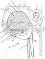
- the round baler (12) is particularly a variable chamber baler, as illustrated in figures 1-3 and 7.
- the flexible endless belt (26) is routed around the rolls (24).
- the flexible endless belt (26) continuously rotates and presses the crop material to form a bale (28).
- the round baler (12) includes a tensioning arm (30) to ensure appropriate tension is maintained in the flexible endless belt (26).
- the tensioning arm (30) moves upwards in response to a growing loop (L) of the belt (26) around the growing bale (28) but maintains an optimum tension in the flexible endless belt (26).
- the tensioning arm (30) may be moved by a hydraulic cylinder (32) and a spring arrangement (34), as schematically illustrated in figure 2 , or solely by a hydraulic cylinder (36), as schematically illustrated in figure 3 .
- a display unit (38) is provided in an operator station (40) of the tractor (10).
- the display unit (38) is configured to continuously indicate change in diameter of the bale (28).
- the diameter of the bale (28) is detected by at least one first sensor (S1).
- the sensor (S1) is positioned on or linked to the tensioning arm (30) and responds to a movement of the tensioning arm (30).
- the first sensor (S1) may be a proximity sensor, an angle sensor, a potentiometer or any other kind of sensor which can be adapted to sense a respective movement of the tensioning arm.
- the sensor (S1) instantaneously indicates the change of the size of the bale (28), in order that the diameter change of the bale (24) is calculated.
- the speed of rotation of the plurality of rolls (24) and hence the operational speed of the flexible endless belt (26) is dependent on the speed of rotation (Vp) of the drive shaft (14), or the PTO respectively.
- the speed of rotation (Vp) of the drive shaft (14) is detected by a second sensor (S2) or derived by other sensing means within the drive train of the tractor (10) indicating the rotation speed of the PTO.
- a controller (42) receives the input from the first sensor (S1) and the second sensor (S2).
- a processor (44) processes the signals received from the first sensor (S1) and the second sensor (S2) to derive a time interval (tb) for completing one rotation of the bale (28).
- a first diameter (D1) of the bale (28) is detected by the sensor (S1) at the end of a preceding rotation, at a first instant of time (T1), as indicated in Figure 6 .
- the processor (44) calculates a time interval (tb) that will be required to complete the subsequent rotation of the bale (28) at a second instant of time (T2).
- the processor (44) computes the first diameter (D1) and the second diameter (D2) for determining the thickness (Th) of the layer (A) of crop material added to the bale (28) between the first instant of time (T1) and the second instant of time (T2), the thickness (Th) of the layer (A) is indicated or displayed in the display unit (38).
- the first sensor (S1) may be positioned at a fixed location on the inner side of the chassis (22) to detect a distance (d) from said fixed location to the surface of the endless belt (26) within a portion of the belt (26) where the belt is building the loop (L) which surrounds the bale (28).
- a distance (d) of the surface of the belt (26) within said loop (L) to the fixed location of the sensor (S1) decreases in proportion to the growing diameter of the bale (28).
- the change of the distance (d) from said fixed location to the surface of the endless belt (26) stays in proportional correlation to the change of diameter of the bale (28) and hence indicates the thickness (Th) of the layer (A) accordingly. Therefore, the sensor (S1), with a fixed location on the inner side of the chassis (22), detects the change of said distance (d) after each rotation of the bale (28) from which the thickness (Th) of the layer (A) can be derived and displayed in the display unit (38).
- the distance (d) from said fixed location to the surface of the endless belt (26) at the second instant of time (T2) subtracted from the distance (d) from said fixed location to the surface of the endless belt (26) at the first instant of time (T1) is equal to the thickness (Th) of the layer (A).
- the first sensor (S1) in this embodiment may be an ultrasonic sensor.
- the operator of the round baler (12) is updated about the thickness (Th) of each layer (A) of the bale (28).
- the operator may be able to optimize the density of the bale (28).
- the information may be also used by the controller (42) to automatically adjust several parameters of the baler (12) to optimize the density of the bale (28). These parameters may include PTO speed, tractor speed, pick-up unit speed and tension of the endless belt (26) adjusted and maintained by the tensioning arm (30).
Landscapes
- Life Sciences & Earth Sciences (AREA)
- Environmental Sciences (AREA)
- Engineering & Computer Science (AREA)
- Mechanical Engineering (AREA)
- Harvester Elements (AREA)
- Storage Of Harvested Produce (AREA)
Abstract
Description
- The present disclosure relates to a round baler. Particularly, the present disclosure relates a variable chamber round baler for intimating an operator of a round baler with information on at least one parameter of a bale, such as, the dimension of a bale and each layer of the bale.
- A baler includes a baling chamber where the agricultural residues from the farm are collected for binding and forming bales with cylindrical layers of crop material. The baler includes one or more press means which are transversely positioned within the baler. Typically, the bales are bound inside the baling chamber before being discharged on the ground. In variable chamber baler, the press means is formed by one or more endless flexible belt. The width of the bale chamber is covered by the endless flexible belt and the sides of the bale chamber are covered by walls. The endless flexible belt is routed about rolls. In a variable chamber baler, the bale is formed by the endless flexible belt. The variable chamber baler, includes a tensioning arm for maintaining tension in the endless flexible belt during baling.
- To form bales of desired density, it is required to optimize the baling process. Currently, to optimize the bale, the operator may be required to adjust the speed of a towing vehicle which tows and powers the baler. However, it might be difficult or not possible for the operator to determine the density of the bales, particularly the change in density of each layer of the crop material . This results in inefficient operation of the baler and causes dissatisfaction to the operator.
- Hence, there is a need for a round baler with an arrangement to provide information to the operator of a variable chamber round baler about the change of density of each layer of the bale.
- The problem addressed by the present invention is that of inability of the operator in determining density of the bales and increasing efficiency of the baler.
- The present invention is defined by the claims, wherein in one embodiment a round baler comprising a drive shaft, a pick-up unit operated by a drive shaft, a baling chamber with at least one rotating press means. The press means is a flexible endless belt. The press means is routed through a plurality of rolling members.
- The pick-up unit is configured to supply a crop material to the baling chamber. The rotating press means is configured to press crop material into a cylindrical bale formed by pressed layers of the crop material. The round baler includes a first sensor disposed within the baler. The first sensor is configured to determine a diameter change of the bale. A second sensor may be configured to detect a speed of the drive shaft. Alternatively, the speed of the drive shaft is known from other parameters of the round baler.
- The round baler includes a controller, a processor and a display unit. The controller may be configured to receive sensed signals of the diameter change from the first sensor and also to receive information of the speed of the drive shaft.
- The processor may be configured to process the speed and the diameter change to determine a thickness of a layer of said crop material. The processor is configured to determine the thickness of the layer corresponding to the rotation of the bale. The processer may calculate a time interval required for one rotation of the bale. The time interval may be determined as a function of the diameter change and the speed.
- The first sensor may be at least one of a proximity sensor, an angle sensor and a potentiometer. The first sensor may be linked to a tensioning arm of the press means, wherein the tensioning arm pivots, moves or changes position according to the change in diameter of the bale. Alternatively, the first sensor may be mounted on any other portion which moves with the change in diameter of the bale. In a further embodiment, the first sensor may also be mounted on outer side of the press means. The second sensor may be a speed sensor. The speed sensor may be a hall-effect based sensor, accelerometer based sensor, variable reluctance speed sensors, eddy current speed sensor, etc.
- The display unit may be configured to indicate thickness of the layer of the crop material for the bale. The display unit may indicate the thickness of the layer of crop material as a graphical representation or a numerical value.
- The drawings show two embodiment examples of the invention, described in more detail below, wherein the brief description of the drawings refers to the accompanying figures in which:
-
Figure 1 illustrates a variable chamber round baler towed by a tractor; -
Figure 2 andFigure 3 illustrates a sectional view of a baling chamber of the variable round baler with a plurality of rolls, flexible endless belt and the tensioning arm with a first embodiment for a sensor mounting; -
Figure 4 schematically illustrates a block diagram for determining the thickness of a bale; -
Figure 5 illustrates diameter of the bale at the end of the preceding rotation of the bale and a subsequent rotation of the bale; and -
Figure 6 schematically illustrates a time duration for detecting the diameters of the bale at the end of each rotation; -
Figure 7 illustrates a sectional view of a baling chamber of the variable round baler with a plurality of rolls, flexible endless belt and the tensioning arm and with an alternative embodiment for a sensor mounting. - Referring to
figure 1 , a tractor (10) is used to tow a round baler (12) along the forward towing direction (V). The round baler (12) is a variable chamber baler. The round baler (12) is powered by a drive shaft (14), driven by a Power Transmission Shaft (PTO, not shown) of the tractor (10). Hereinafter, all indicated directions and location of the round baler (12), such as, forward, backward, rear, front, up, above, down, left and right shall be determined with reference to the forward towing direction (V) of the round baler (12) in the field. The round baler (12) includes a pick-up unit (16) provided at the front end of the round baler (12) to collect the residual product, such as hay, straw or other crop, from the ground and to convey it towards a cutting rotor (not shown), from which the crop enters into a baling chamber (18) of the round baler (12). The round baler (12) is mounted on a support frame (20) of a chassis (22) and includes the baling chamber (18) with a plurality of rolls (24) and press means, such as, a flexible endless belt (26), routed around and driven by the rolls (24). The round baler (12) is particularly a variable chamber baler, as illustrated infigures 1-3 and 7. - The flexible endless belt (26) is routed around the rolls (24). The flexible endless belt (26) continuously rotates and presses the crop material to form a bale (28). The round baler (12) includes a tensioning arm (30) to ensure appropriate tension is maintained in the flexible endless belt (26). As the size of the bale (28) increases, the tensioning arm (30) moves upwards in response to a growing loop (L) of the belt (26) around the growing bale (28) but maintains an optimum tension in the flexible endless belt (26). The tensioning arm (30) may be moved by a hydraulic cylinder (32) and a spring arrangement (34), as schematically illustrated in
figure 2 , or solely by a hydraulic cylinder (36), as schematically illustrated infigure 3 . - Referring to
figures 1 to 3 , a display unit (38) is provided in an operator station (40) of the tractor (10). The display unit (38) is configured to continuously indicate change in diameter of the bale (28). The diameter of the bale (28) is detected by at least one first sensor (S1). The sensor (S1) is positioned on or linked to the tensioning arm (30) and responds to a movement of the tensioning arm (30). The first sensor (S1) may be a proximity sensor, an angle sensor, a potentiometer or any other kind of sensor which can be adapted to sense a respective movement of the tensioning arm. As discussed earlier, as the size of the bale (28) increases, the tensioning arm (30) moves upwards. Hence, the sensor (S1) instantaneously indicates the change of the size of the bale (28), in order that the diameter change of the bale (24) is calculated. - The speed of rotation of the plurality of rolls (24) and hence the operational speed of the flexible endless belt (26) is dependent on the speed of rotation (Vp) of the drive shaft (14), or the PTO respectively. The speed of rotation (Vp) of the drive shaft (14) is detected by a second sensor (S2) or derived by other sensing means within the drive train of the tractor (10) indicating the rotation speed of the PTO.
- Referring to
figure 4, figure 5, figure 6 , a controller (42) receives the input from the first sensor (S1) and the second sensor (S2). A processor (44) processes the signals received from the first sensor (S1) and the second sensor (S2) to derive a time interval (tb) for completing one rotation of the bale (28). Thus, for example, as illustrated inFigure 5 , a first diameter (D1) of the bale (28) is detected by the sensor (S1) at the end of a preceding rotation, at a first instant of time (T1), as indicated inFigure 6 . At the first instant of time (T1), when the diameter (D1) is detected, the processor (44) calculates a time interval (tb) that will be required to complete the subsequent rotation of the bale (28) at a second instant of time (T2). The calculation for the time interval (tb) is provided in equation (i):
- After one rotation of the bale (28), one layer (A) of the crop material is added over the bale (28), thereby changing the first diameter (D1) of the bale (28) to a second diameter (D2) at the end of the preceding rotation. Thus, by adding the time interval (tb), derived from equation (i), to the first instant of time (T1), the processor (44) calculates the second instant of time (T2) when the subsequent rotation will be completed, derived from equation (ii) and (iii):


- A second diameter (D2) of the bale (28), is detected by the first sensor (S1) at the second instant of time (T2) and considered by the processor (44) for further calculation of a layer thickness (Th) of the layer (A) derived from equation (iv):

- As the processor (44) computes the first diameter (D1) and the second diameter (D2) for determining the thickness (Th) of the layer (A) of crop material added to the bale (28) between the first instant of time (T1) and the second instant of time (T2), the thickness (Th) of the layer (A) is indicated or displayed in the display unit (38).
- In accordance with an alternate embodiment, shown in
figure 7 , instead of having the first sensor (S1) positioned on or linked to the tensioning arm (30), the first sensor (S1) may be positioned at a fixed location on the inner side of the chassis (22) to detect a distance (d) from said fixed location to the surface of the endless belt (26) within a portion of the belt (26) where the belt is building the loop (L) which surrounds the bale (28). As the loop (L) grows during a baling process a distance (d) of the surface of the belt (26) within said loop (L) to the fixed location of the sensor (S1) decreases in proportion to the growing diameter of the bale (28). Due to a pre-given routing arrangement of the belt (26) around the rolls (24) and the geometrical dimensions and arrangement of the of the rolls within the baler (12), respectively, the change of the distance (d) from said fixed location to the surface of the endless belt (26) stays in proportional correlation to the change of diameter of the bale (28) and hence indicates the thickness (Th) of the layer (A) accordingly. Therefore, the sensor (S1), with a fixed location on the inner side of the chassis (22), detects the change of said distance (d) after each rotation of the bale (28) from which the thickness (Th) of the layer (A) can be derived and displayed in the display unit (38). In other words, in this embodiment, the distance (d) from said fixed location to the surface of the endless belt (26) at the second instant of time (T2) subtracted from the distance (d) from said fixed location to the surface of the endless belt (26) at the first instant of time (T1) is equal to the thickness (Th) of the layer (A). The first sensor (S1) in this embodiment may be an ultrasonic sensor. - Thus, in accordance with the present invention, the operator of the round baler (12) is updated about the thickness (Th) of each layer (A) of the bale (28). Using the information about the thickness (Th) of each layer (A) of the bale (28), the operator may be able to optimize the density of the bale (28). The information may be also used by the controller (42) to automatically adjust several parameters of the baler (12) to optimize the density of the bale (28). These parameters may include PTO speed, tractor speed, pick-up unit speed and tension of the endless belt (26) adjusted and maintained by the tensioning arm (30).
Claims (10)
- A round baler (12) comprising:a drive shaft (14);a pick-up unit (16) operated by said drive shaft (14), said pick-up unit (16) being configured to supply a crop material;a baling chamber (18) receives said crop material from said pick-up unit (16); andat least one press means (26) disposed within said baling chamber (18), said press means (26) being configured to press crop material into a cylindrical bale (28) formed by pressed layers (A) of the crop material;characterized in that,a first sensor (S1) disposed within said baler (12), said first sensor (S1) being configured to determine a diameter change of said bale (28);a second sensor (S2) configured to detect a speed of the drive shaft (14);a controller (42) configured to receive sensed signals of the speed (Vp) of the drive shaft (14) and the diameter change from said first sensor (S1) and said second sensor (S2) respectively;a processor (44) configured to process said speed (Vp) and said diameter change to determine a thickness (Th) of a layer (A) of said crop material; anda display unit (38) configured to indicate said thickness (Th) of the layer (A) of said crop material for the bale (28).
- The round baler (12) as claimed in claim 1, wherein the processor (44) is configured to determine the thickness (Th) of the layer corresponding to the rotation of the bale (28).
- The round baler (12) as claimed in claim 1 or claim 2, wherein said processer (44) calculates a time interval (tb) required for one rotation of the bale (28).
- The round baler (12) as claimed in claim 3, wherein said time interval (tb) is determined by a function of the diameter change and said speed (Vp).
- The round baler (12) as claimed in one of the claims 1 to 4, wherein the first sensor (S1) is at least one of a proximity sensor, an angle sensor and a potentiometer.
- The round baler (12) as claimed in one of the claims 1 to 5, wherein the first sensor (S1) is linked to a tensioning arm (30) of the press means (26).
- The round baler (12) as claimed in one of the claims 1 to 5, wherein the first sensor (S1) is mounted at a fixed location on an inner side of a chassis (22) of the round baler (12) to detect a distance (d) from said fixed location to the surface of the endless belt (26) within a portion of the belt (26) where the belt is building a loop (L) which surrounds the bale (28).
- The round baler (12) as claimed in one of the claims 1 to 7, wherein the second sensor (S2) is a speed sensor to detect a rotation speed of the drive shaft (14) and/or of the endless belt (26).
- The round baler (12) as claimed in one of the claims 1 to 8, wherein the tensioning arm (30) is operated by a combination of a hydraulic cylinder (32) and a spring (34).
- The round baler (12) as claimed in one of the claims 1 to 8, wherein the tensioning arm (30) is operated by a hydraulic cylinder (32).
Priority Applications (2)
| Application Number | Priority Date | Filing Date | Title |
|---|---|---|---|
| EP19151009.8A EP3679784B1 (en) | 2019-01-09 | 2019-01-09 | Round baler |
| US16/666,447 US20200214219A1 (en) | 2019-01-09 | 2019-10-29 | Method to optimize the density of the bale on a round baler |
Applications Claiming Priority (1)
| Application Number | Priority Date | Filing Date | Title |
|---|---|---|---|
| EP19151009.8A EP3679784B1 (en) | 2019-01-09 | 2019-01-09 | Round baler |
Publications (2)
| Publication Number | Publication Date |
|---|---|
| EP3679784A1 true EP3679784A1 (en) | 2020-07-15 |
| EP3679784B1 EP3679784B1 (en) | 2021-12-01 |
Family
ID=65011916
Family Applications (1)
| Application Number | Title | Priority Date | Filing Date |
|---|---|---|---|
| EP19151009.8A Active EP3679784B1 (en) | 2019-01-09 | 2019-01-09 | Round baler |
Country Status (2)
| Country | Link |
|---|---|
| US (1) | US20200214219A1 (en) |
| EP (1) | EP3679784B1 (en) |
Cited By (4)
| Publication number | Priority date | Publication date | Assignee | Title |
|---|---|---|---|---|
| CN111820017A (en) * | 2020-07-24 | 2020-10-27 | 利辛县江淮扬天汽车有限公司 | Bundling device of corn harvesting and bundling machine |
| EP4356719A1 (en) * | 2022-10-19 | 2024-04-24 | Deere & Company | Round bale pre-completion yield calculation |
| US12490681B2 (en) | 2021-04-20 | 2025-12-09 | Agco Corporation | Systems for monitoring and using mat thickness and bale growth rate |
| EP4714255A1 (en) * | 2024-09-19 | 2026-03-25 | Deere & Company | Control system and method for balers using crop constituents |
Families Citing this family (4)
| Publication number | Priority date | Publication date | Assignee | Title |
|---|---|---|---|---|
| US11134614B2 (en) * | 2018-10-10 | 2021-10-05 | Deere & Company | Productivity increase for a round baler |
| US12336457B2 (en) | 2022-06-23 | 2025-06-24 | Deere & Company | Auxiliary pressure circuit for a round baler |
| US12201065B2 (en) | 2022-11-28 | 2025-01-21 | Deere & Company | Round baler implement having forming belt pin wear detection system |
| CN118923357B (en) * | 2024-09-25 | 2026-03-24 | 安徽海森曼农业机械有限公司 | A belt-driven variable diameter round baler and its control method |
Citations (6)
| Publication number | Priority date | Publication date | Assignee | Title |
|---|---|---|---|---|
| JPH07132019A (en) * | 1993-11-10 | 1995-05-23 | Seirei Ind Co Ltd | Roll baler |
| US5615544A (en) * | 1996-02-13 | 1997-04-01 | New Holland North America, Inc. | System for monitoring the shape of round bales |
| EP1813146A2 (en) * | 2006-01-31 | 2007-08-01 | Deere & Company | Tractor and baler combination with automatic baling and steering control |
| US20120042792A1 (en) * | 2010-08-23 | 2012-02-23 | Smith Kevin M | Automatic bale size calibration on round balers |
| EP2923560A1 (en) * | 2014-03-25 | 2015-09-30 | CNH Industrial Belgium nv | Baling system having a bale position sensor |
| EP3192347A1 (en) * | 2016-01-14 | 2017-07-19 | CNH Industrial Belgium nv | Continuous harvester with crop supply chamber |
Family Cites Families (3)
| Publication number | Priority date | Publication date | Assignee | Title |
|---|---|---|---|---|
| DE19718229A1 (en) * | 1997-04-30 | 1998-11-05 | Claas Usines France | Agricultural round baler |
| FR2811654B1 (en) * | 2000-07-13 | 2003-11-21 | Inst Tech Du Lin | METHOD FOR CONTROLLING THICKNESS OF WOUND TABLECLOTH AND DEVICE FOR IMPLEMENTING SAME |
| US20140261023A1 (en) * | 2013-03-15 | 2014-09-18 | Cnh Industrial America Llc | Bale forming control system and method |
-
2019
- 2019-01-09 EP EP19151009.8A patent/EP3679784B1/en active Active
- 2019-10-29 US US16/666,447 patent/US20200214219A1/en not_active Abandoned
Patent Citations (6)
| Publication number | Priority date | Publication date | Assignee | Title |
|---|---|---|---|---|
| JPH07132019A (en) * | 1993-11-10 | 1995-05-23 | Seirei Ind Co Ltd | Roll baler |
| US5615544A (en) * | 1996-02-13 | 1997-04-01 | New Holland North America, Inc. | System for monitoring the shape of round bales |
| EP1813146A2 (en) * | 2006-01-31 | 2007-08-01 | Deere & Company | Tractor and baler combination with automatic baling and steering control |
| US20120042792A1 (en) * | 2010-08-23 | 2012-02-23 | Smith Kevin M | Automatic bale size calibration on round balers |
| EP2923560A1 (en) * | 2014-03-25 | 2015-09-30 | CNH Industrial Belgium nv | Baling system having a bale position sensor |
| EP3192347A1 (en) * | 2016-01-14 | 2017-07-19 | CNH Industrial Belgium nv | Continuous harvester with crop supply chamber |
Cited By (5)
| Publication number | Priority date | Publication date | Assignee | Title |
|---|---|---|---|---|
| CN111820017A (en) * | 2020-07-24 | 2020-10-27 | 利辛县江淮扬天汽车有限公司 | Bundling device of corn harvesting and bundling machine |
| US12490681B2 (en) | 2021-04-20 | 2025-12-09 | Agco Corporation | Systems for monitoring and using mat thickness and bale growth rate |
| EP4356719A1 (en) * | 2022-10-19 | 2024-04-24 | Deere & Company | Round bale pre-completion yield calculation |
| US12402568B2 (en) | 2022-10-19 | 2025-09-02 | Deere & Company | Round bale pre-completion yield calculation |
| EP4714255A1 (en) * | 2024-09-19 | 2026-03-25 | Deere & Company | Control system and method for balers using crop constituents |
Also Published As
| Publication number | Publication date |
|---|---|
| EP3679784B1 (en) | 2021-12-01 |
| US20200214219A1 (en) | 2020-07-09 |
Similar Documents
| Publication | Publication Date | Title |
|---|---|---|
| EP3679784B1 (en) | Round baler | |
| US10827675B2 (en) | Drive system of a utility vehicle | |
| EP3315016B1 (en) | Round baler and method of creating a yield map for such a round baler | |
| US8141480B2 (en) | Automatic bale size calibration on round balers | |
| EP2700297B1 (en) | Current sensing of actuators on a round baler | |
| US5615544A (en) | System for monitoring the shape of round bales | |
| EP3968752B1 (en) | Variable chamber round baler | |
| EP3461323B1 (en) | Baler with dry matter content detection system | |
| EP4108067B1 (en) | Agricultural implement system with a controller for detecting and mitigating plug conditions | |
| US6248963B1 (en) | Bale-density measuring system for baler | |
| CN110495304B (en) | Round bundling machine | |
| EP4278886A1 (en) | Round baler wrap usage indicator | |
| EP2698055B1 (en) | Measuring distance for bale size in a round baler | |
| EP4188069B1 (en) | A baler and method and apparatus for determining uniformity of the density of a round bale | |
| EP2742795B1 (en) | Even bale block for monitoring bale shape in a round baler | |
| US10750669B2 (en) | Round baler, combination of an agricultural vehicle with such a baler and method for forming round bales | |
| US12029169B2 (en) | Baling machine including a pre-baling chamber rotative packer/stuffer | |
| US12408592B2 (en) | Agricultural baler system with bale stall identification | |
| US9936644B2 (en) | Round baler with apparatus for guiding a pressing belt | |
| US20230115928A1 (en) | Baling Apparatus | |
| EP4570057A1 (en) | Variable speed pickup for round baler | |
| EP4570056A1 (en) | Variable pickup speed control for controlling shape of a round bale | |
| EP4684632A1 (en) | Bale moisture measurement | |
| EP4666836A1 (en) | Agricultural implement system with a controller for detecting and mitigating plug conditions | |
| US20250185547A1 (en) | Feedrate control for round baler |
Legal Events
| Date | Code | Title | Description |
|---|---|---|---|
| PUAI | Public reference made under article 153(3) epc to a published international application that has entered the european phase |
Free format text: ORIGINAL CODE: 0009012 |
|
| STAA | Information on the status of an ep patent application or granted ep patent |
Free format text: STATUS: THE APPLICATION HAS BEEN PUBLISHED |
|
| AK | Designated contracting states |
Kind code of ref document: A1 Designated state(s): AL AT BE BG CH CY CZ DE DK EE ES FI FR GB GR HR HU IE IS IT LI LT LU LV MC MK MT NL NO PL PT RO RS SE SI SK SM TR |
|
| AX | Request for extension of the european patent |
Extension state: BA ME |
|
| STAA | Information on the status of an ep patent application or granted ep patent |
Free format text: STATUS: REQUEST FOR EXAMINATION WAS MADE |
|
| 17P | Request for examination filed |
Effective date: 20210115 |
|
| RBV | Designated contracting states (corrected) |
Designated state(s): AL AT BE BG CH CY CZ DE DK EE ES FI FR GB GR HR HU IE IS IT LI LT LU LV MC MK MT NL NO PL PT RO RS SE SI SK SM TR |
|
| GRAP | Despatch of communication of intention to grant a patent |
Free format text: ORIGINAL CODE: EPIDOSNIGR1 |
|
| STAA | Information on the status of an ep patent application or granted ep patent |
Free format text: STATUS: GRANT OF PATENT IS INTENDED |
|
| INTG | Intention to grant announced |
Effective date: 20210701 |
|
| GRAS | Grant fee paid |
Free format text: ORIGINAL CODE: EPIDOSNIGR3 |
|
| GRAA | (expected) grant |
Free format text: ORIGINAL CODE: 0009210 |
|
| STAA | Information on the status of an ep patent application or granted ep patent |
Free format text: STATUS: THE PATENT HAS BEEN GRANTED |
|
| AK | Designated contracting states |
Kind code of ref document: B1 Designated state(s): AL AT BE BG CH CY CZ DE DK EE ES FI FR GB GR HR HU IE IS IT LI LT LU LV MC MK MT NL NO PL PT RO RS SE SI SK SM TR |
|
| REG | Reference to a national code |
Ref country code: GB Ref legal event code: FG4D |
|
| REG | Reference to a national code |
Ref country code: AT Ref legal event code: REF Ref document number: 1450893 Country of ref document: AT Kind code of ref document: T Effective date: 20211215 Ref country code: CH Ref legal event code: EP |
|
| REG | Reference to a national code |
Ref country code: IE Ref legal event code: FG4D |
|
| REG | Reference to a national code |
Ref country code: DE Ref legal event code: R096 Ref document number: 602019009588 Country of ref document: DE |
|
| REG | Reference to a national code |
Ref country code: LT Ref legal event code: MG9D |
|
| REG | Reference to a national code |
Ref country code: NL Ref legal event code: MP Effective date: 20211201 |
|
| REG | Reference to a national code |
Ref country code: AT Ref legal event code: MK05 Ref document number: 1450893 Country of ref document: AT Kind code of ref document: T Effective date: 20211201 |
|
| PG25 | Lapsed in a contracting state [announced via postgrant information from national office to epo] |
Ref country code: RS Free format text: LAPSE BECAUSE OF FAILURE TO SUBMIT A TRANSLATION OF THE DESCRIPTION OR TO PAY THE FEE WITHIN THE PRESCRIBED TIME-LIMIT Effective date: 20211201 Ref country code: LT Free format text: LAPSE BECAUSE OF FAILURE TO SUBMIT A TRANSLATION OF THE DESCRIPTION OR TO PAY THE FEE WITHIN THE PRESCRIBED TIME-LIMIT Effective date: 20211201 Ref country code: FI Free format text: LAPSE BECAUSE OF FAILURE TO SUBMIT A TRANSLATION OF THE DESCRIPTION OR TO PAY THE FEE WITHIN THE PRESCRIBED TIME-LIMIT Effective date: 20211201 Ref country code: BG Free format text: LAPSE BECAUSE OF FAILURE TO SUBMIT A TRANSLATION OF THE DESCRIPTION OR TO PAY THE FEE WITHIN THE PRESCRIBED TIME-LIMIT Effective date: 20220301 Ref country code: AT Free format text: LAPSE BECAUSE OF FAILURE TO SUBMIT A TRANSLATION OF THE DESCRIPTION OR TO PAY THE FEE WITHIN THE PRESCRIBED TIME-LIMIT Effective date: 20211201 |
|
| PG25 | Lapsed in a contracting state [announced via postgrant information from national office to epo] |
Ref country code: SE Free format text: LAPSE BECAUSE OF FAILURE TO SUBMIT A TRANSLATION OF THE DESCRIPTION OR TO PAY THE FEE WITHIN THE PRESCRIBED TIME-LIMIT Effective date: 20211201 Ref country code: PL Free format text: LAPSE BECAUSE OF FAILURE TO SUBMIT A TRANSLATION OF THE DESCRIPTION OR TO PAY THE FEE WITHIN THE PRESCRIBED TIME-LIMIT Effective date: 20211201 Ref country code: NO Free format text: LAPSE BECAUSE OF FAILURE TO SUBMIT A TRANSLATION OF THE DESCRIPTION OR TO PAY THE FEE WITHIN THE PRESCRIBED TIME-LIMIT Effective date: 20220301 Ref country code: LV Free format text: LAPSE BECAUSE OF FAILURE TO SUBMIT A TRANSLATION OF THE DESCRIPTION OR TO PAY THE FEE WITHIN THE PRESCRIBED TIME-LIMIT Effective date: 20211201 Ref country code: HR Free format text: LAPSE BECAUSE OF FAILURE TO SUBMIT A TRANSLATION OF THE DESCRIPTION OR TO PAY THE FEE WITHIN THE PRESCRIBED TIME-LIMIT Effective date: 20211201 Ref country code: GR Free format text: LAPSE BECAUSE OF FAILURE TO SUBMIT A TRANSLATION OF THE DESCRIPTION OR TO PAY THE FEE WITHIN THE PRESCRIBED TIME-LIMIT Effective date: 20220302 Ref country code: ES Free format text: LAPSE BECAUSE OF FAILURE TO SUBMIT A TRANSLATION OF THE DESCRIPTION OR TO PAY THE FEE WITHIN THE PRESCRIBED TIME-LIMIT Effective date: 20211201 |
|
| PG25 | Lapsed in a contracting state [announced via postgrant information from national office to epo] |
Ref country code: NL Free format text: LAPSE BECAUSE OF FAILURE TO SUBMIT A TRANSLATION OF THE DESCRIPTION OR TO PAY THE FEE WITHIN THE PRESCRIBED TIME-LIMIT Effective date: 20211201 |
|
| PG25 | Lapsed in a contracting state [announced via postgrant information from national office to epo] |
Ref country code: SM Free format text: LAPSE BECAUSE OF FAILURE TO SUBMIT A TRANSLATION OF THE DESCRIPTION OR TO PAY THE FEE WITHIN THE PRESCRIBED TIME-LIMIT Effective date: 20211201 Ref country code: SK Free format text: LAPSE BECAUSE OF FAILURE TO SUBMIT A TRANSLATION OF THE DESCRIPTION OR TO PAY THE FEE WITHIN THE PRESCRIBED TIME-LIMIT Effective date: 20211201 Ref country code: RO Free format text: LAPSE BECAUSE OF FAILURE TO SUBMIT A TRANSLATION OF THE DESCRIPTION OR TO PAY THE FEE WITHIN THE PRESCRIBED TIME-LIMIT Effective date: 20211201 Ref country code: PT Free format text: LAPSE BECAUSE OF FAILURE TO SUBMIT A TRANSLATION OF THE DESCRIPTION OR TO PAY THE FEE WITHIN THE PRESCRIBED TIME-LIMIT Effective date: 20220401 Ref country code: EE Free format text: LAPSE BECAUSE OF FAILURE TO SUBMIT A TRANSLATION OF THE DESCRIPTION OR TO PAY THE FEE WITHIN THE PRESCRIBED TIME-LIMIT Effective date: 20211201 Ref country code: CZ Free format text: LAPSE BECAUSE OF FAILURE TO SUBMIT A TRANSLATION OF THE DESCRIPTION OR TO PAY THE FEE WITHIN THE PRESCRIBED TIME-LIMIT Effective date: 20211201 |
|
| PG25 | Lapsed in a contracting state [announced via postgrant information from national office to epo] |
Ref country code: MC Free format text: LAPSE BECAUSE OF FAILURE TO SUBMIT A TRANSLATION OF THE DESCRIPTION OR TO PAY THE FEE WITHIN THE PRESCRIBED TIME-LIMIT Effective date: 20211201 |
|
| REG | Reference to a national code |
Ref country code: CH Ref legal event code: PL |
|
| REG | Reference to a national code |
Ref country code: DE Ref legal event code: R097 Ref document number: 602019009588 Country of ref document: DE |
|
| PG25 | Lapsed in a contracting state [announced via postgrant information from national office to epo] |
Ref country code: IS Free format text: LAPSE BECAUSE OF FAILURE TO SUBMIT A TRANSLATION OF THE DESCRIPTION OR TO PAY THE FEE WITHIN THE PRESCRIBED TIME-LIMIT Effective date: 20220401 |
|
| REG | Reference to a national code |
Ref country code: BE Ref legal event code: MM Effective date: 20220131 |
|
| PLBE | No opposition filed within time limit |
Free format text: ORIGINAL CODE: 0009261 |
|
| STAA | Information on the status of an ep patent application or granted ep patent |
Free format text: STATUS: NO OPPOSITION FILED WITHIN TIME LIMIT |
|
| PG25 | Lapsed in a contracting state [announced via postgrant information from national office to epo] |
Ref country code: LU Free format text: LAPSE BECAUSE OF NON-PAYMENT OF DUE FEES Effective date: 20220109 Ref country code: DK Free format text: LAPSE BECAUSE OF FAILURE TO SUBMIT A TRANSLATION OF THE DESCRIPTION OR TO PAY THE FEE WITHIN THE PRESCRIBED TIME-LIMIT Effective date: 20211201 Ref country code: AL Free format text: LAPSE BECAUSE OF FAILURE TO SUBMIT A TRANSLATION OF THE DESCRIPTION OR TO PAY THE FEE WITHIN THE PRESCRIBED TIME-LIMIT Effective date: 20211201 |
|
| 26N | No opposition filed |
Effective date: 20220902 |
|
| PG25 | Lapsed in a contracting state [announced via postgrant information from national office to epo] |
Ref country code: SI Free format text: LAPSE BECAUSE OF FAILURE TO SUBMIT A TRANSLATION OF THE DESCRIPTION OR TO PAY THE FEE WITHIN THE PRESCRIBED TIME-LIMIT Effective date: 20211201 Ref country code: BE Free format text: LAPSE BECAUSE OF NON-PAYMENT OF DUE FEES Effective date: 20220131 |
|
| PG25 | Lapsed in a contracting state [announced via postgrant information from national office to epo] |
Ref country code: LI Free format text: LAPSE BECAUSE OF NON-PAYMENT OF DUE FEES Effective date: 20220131 Ref country code: CH Free format text: LAPSE BECAUSE OF NON-PAYMENT OF DUE FEES Effective date: 20220131 |
|
| PG25 | Lapsed in a contracting state [announced via postgrant information from national office to epo] |
Ref country code: IE Free format text: LAPSE BECAUSE OF NON-PAYMENT OF DUE FEES Effective date: 20220109 |
|
| PG25 | Lapsed in a contracting state [announced via postgrant information from national office to epo] |
Ref country code: IT Free format text: LAPSE BECAUSE OF FAILURE TO SUBMIT A TRANSLATION OF THE DESCRIPTION OR TO PAY THE FEE WITHIN THE PRESCRIBED TIME-LIMIT Effective date: 20211201 |
|
| PG25 | Lapsed in a contracting state [announced via postgrant information from national office to epo] |
Ref country code: MK Free format text: LAPSE BECAUSE OF FAILURE TO SUBMIT A TRANSLATION OF THE DESCRIPTION OR TO PAY THE FEE WITHIN THE PRESCRIBED TIME-LIMIT Effective date: 20211201 Ref country code: CY Free format text: LAPSE BECAUSE OF FAILURE TO SUBMIT A TRANSLATION OF THE DESCRIPTION OR TO PAY THE FEE WITHIN THE PRESCRIBED TIME-LIMIT Effective date: 20211201 |
|
| PG25 | Lapsed in a contracting state [announced via postgrant information from national office to epo] |
Ref country code: HU Free format text: LAPSE BECAUSE OF FAILURE TO SUBMIT A TRANSLATION OF THE DESCRIPTION OR TO PAY THE FEE WITHIN THE PRESCRIBED TIME-LIMIT; INVALID AB INITIO Effective date: 20190109 |
|
| PG25 | Lapsed in a contracting state [announced via postgrant information from national office to epo] |
Ref country code: MT Free format text: LAPSE BECAUSE OF FAILURE TO SUBMIT A TRANSLATION OF THE DESCRIPTION OR TO PAY THE FEE WITHIN THE PRESCRIBED TIME-LIMIT Effective date: 20211201 |
|
| PG25 | Lapsed in a contracting state [announced via postgrant information from national office to epo] |
Ref country code: TR Free format text: LAPSE BECAUSE OF FAILURE TO SUBMIT A TRANSLATION OF THE DESCRIPTION OR TO PAY THE FEE WITHIN THE PRESCRIBED TIME-LIMIT Effective date: 20211201 |
|
| PGFP | Annual fee paid to national office [announced via postgrant information from national office to epo] |
Ref country code: GB Payment date: 20260127 Year of fee payment: 8 |
|
| PGFP | Annual fee paid to national office [announced via postgrant information from national office to epo] |
Ref country code: DE Payment date: 20251219 Year of fee payment: 8 |
|
| PGFP | Annual fee paid to national office [announced via postgrant information from national office to epo] |
Ref country code: FR Payment date: 20260126 Year of fee payment: 8 |