EP3679678B1 - Methods and systems for joint access point mimo transmissions - Google Patents
Methods and systems for joint access point mimo transmissions Download PDFInfo
- Publication number
- EP3679678B1 EP3679678B1 EP18779148.8A EP18779148A EP3679678B1 EP 3679678 B1 EP3679678 B1 EP 3679678B1 EP 18779148 A EP18779148 A EP 18779148A EP 3679678 B1 EP3679678 B1 EP 3679678B1
- Authority
- EP
- European Patent Office
- Prior art keywords
- transmission
- devices
- aps
- message
- stas
- Prior art date
- Legal status (The legal status is an assumption and is not a legal conclusion. Google has not performed a legal analysis and makes no representation as to the accuracy of the status listed.)
- Active
Links
- 230000005540 biological transmission Effects 0.000 title claims description 284
- 238000000034 method Methods 0.000 title claims description 42
- 238000012937 correction Methods 0.000 claims description 8
- 230000004044 response Effects 0.000 claims description 8
- YLKFDHTUAUWZPQ-UHFFFAOYSA-N N-Nitrosodi-n-propylamine Chemical compound CCCN(N=O)CCC YLKFDHTUAUWZPQ-UHFFFAOYSA-N 0.000 claims 2
- 238000004891 communication Methods 0.000 description 125
- 230000006870 function Effects 0.000 description 15
- 230000008859 change Effects 0.000 description 14
- 238000013459 approach Methods 0.000 description 12
- 238000005516 engineering process Methods 0.000 description 11
- 230000001413 cellular effect Effects 0.000 description 10
- 238000012545 processing Methods 0.000 description 10
- 239000011159 matrix material Substances 0.000 description 9
- 238000005259 measurement Methods 0.000 description 7
- 230000001360 synchronised effect Effects 0.000 description 6
- OVGWMUWIRHGGJP-WVDJAODQSA-N (z)-7-[(1s,3r,4r,5s)-3-[(e,3r)-3-hydroxyoct-1-enyl]-6-thiabicyclo[3.1.1]heptan-4-yl]hept-5-enoic acid Chemical compound OC(=O)CCC\C=C/C[C@@H]1[C@@H](/C=C/[C@H](O)CCCCC)C[C@@H]2S[C@H]1C2 OVGWMUWIRHGGJP-WVDJAODQSA-N 0.000 description 5
- 101100161473 Arabidopsis thaliana ABCB25 gene Proteins 0.000 description 5
- 101000988961 Escherichia coli Heat-stable enterotoxin A2 Proteins 0.000 description 5
- 101100096893 Mus musculus Sult2a1 gene Proteins 0.000 description 5
- 101150081243 STA1 gene Proteins 0.000 description 5
- 230000003287 optical effect Effects 0.000 description 5
- 238000004590 computer program Methods 0.000 description 4
- 230000010363 phase shift Effects 0.000 description 4
- 230000015572 biosynthetic process Effects 0.000 description 3
- 230000007423 decrease Effects 0.000 description 3
- 230000006855 networking Effects 0.000 description 3
- 230000000737 periodic effect Effects 0.000 description 3
- 230000008569 process Effects 0.000 description 3
- 238000001514 detection method Methods 0.000 description 2
- 239000000835 fiber Substances 0.000 description 2
- 230000000977 initiatory effect Effects 0.000 description 2
- 230000002452 interceptive effect Effects 0.000 description 2
- 230000008520 organization Effects 0.000 description 2
- 230000002441 reversible effect Effects 0.000 description 2
- 230000009471 action Effects 0.000 description 1
- 230000002411 adverse Effects 0.000 description 1
- 230000008901 benefit Effects 0.000 description 1
- 230000002457 bidirectional effect Effects 0.000 description 1
- 230000033228 biological regulation Effects 0.000 description 1
- 238000004364 calculation method Methods 0.000 description 1
- 239000000969 carrier Substances 0.000 description 1
- 239000003795 chemical substances by application Substances 0.000 description 1
- 230000008878 coupling Effects 0.000 description 1
- 238000010168 coupling process Methods 0.000 description 1
- 238000005859 coupling reaction Methods 0.000 description 1
- 238000010586 diagram Methods 0.000 description 1
- 230000006872 improvement Effects 0.000 description 1
- 230000007774 longterm Effects 0.000 description 1
- 230000007246 mechanism Effects 0.000 description 1
- 230000003278 mimic effect Effects 0.000 description 1
- 238000010295 mobile communication Methods 0.000 description 1
- 238000002250 neutron powder diffraction Methods 0.000 description 1
- 239000005022 packaging material Substances 0.000 description 1
- 230000011664 signaling Effects 0.000 description 1
- 230000003595 spectral effect Effects 0.000 description 1
- 238000001228 spectrum Methods 0.000 description 1
- 238000012549 training Methods 0.000 description 1
- 238000012546 transfer Methods 0.000 description 1
- 239000013598 vector Substances 0.000 description 1
Images


Classifications
-
- H—ELECTRICITY
- H04—ELECTRIC COMMUNICATION TECHNIQUE
- H04B—TRANSMISSION
- H04B7/00—Radio transmission systems, i.e. using radiation field
- H04B7/02—Diversity systems; Multi-antenna system, i.e. transmission or reception using multiple antennas
- H04B7/022—Site diversity; Macro-diversity
- H04B7/024—Co-operative use of antennas of several sites, e.g. in co-ordinated multipoint or co-operative multiple-input multiple-output [MIMO] systems
-
- H—ELECTRICITY
- H04—ELECTRIC COMMUNICATION TECHNIQUE
- H04B—TRANSMISSION
- H04B7/00—Radio transmission systems, i.e. using radiation field
- H04B7/02—Diversity systems; Multi-antenna system, i.e. transmission or reception using multiple antennas
- H04B7/04—Diversity systems; Multi-antenna system, i.e. transmission or reception using multiple antennas using two or more spaced independent antennas
- H04B7/0413—MIMO systems
- H04B7/0417—Feedback systems
-
- H—ELECTRICITY
- H04—ELECTRIC COMMUNICATION TECHNIQUE
- H04B—TRANSMISSION
- H04B7/00—Radio transmission systems, i.e. using radiation field
- H04B7/02—Diversity systems; Multi-antenna system, i.e. transmission or reception using multiple antennas
- H04B7/04—Diversity systems; Multi-antenna system, i.e. transmission or reception using multiple antennas using two or more spaced independent antennas
- H04B7/0413—MIMO systems
- H04B7/0456—Selection of precoding matrices or codebooks, e.g. using matrices antenna weighting
-
- H—ELECTRICITY
- H04—ELECTRIC COMMUNICATION TECHNIQUE
- H04L—TRANSMISSION OF DIGITAL INFORMATION, e.g. TELEGRAPHIC COMMUNICATION
- H04L5/00—Arrangements affording multiple use of the transmission path
- H04L5/003—Arrangements for allocating sub-channels of the transmission path
- H04L5/0032—Distributed allocation, i.e. involving a plurality of allocating devices, each making partial allocation
- H04L5/0035—Resource allocation in a cooperative multipoint environment
Landscapes
- Engineering & Computer Science (AREA)
- Signal Processing (AREA)
- Computer Networks & Wireless Communication (AREA)
- Mobile Radio Communication Systems (AREA)
Description
- This application relates generally to wireless communication, and more specifically to systems and methods for joint access point MIMO transmissions.
- Wireless communications systems are widely deployed to provide various types of communication content such as voice, video, packet data, messaging, broadcast, and so on. The wireless communications systems may utilize communications networks to exchange messages among several interacting spatially-separated devices. Networks may be classified according to geographic scope, which could be, for example, a metropolitan area, a local area, or a personal area. Such networks would be designated respectively as a wide area network (WAN), metropolitan area network (MAN), local area network (LAN), wireless local area network (WLAN), or personal area network (PAN). Networks also differ according to the switching/routing technique used to interconnect the various network nodes and devices (e.g., circuit switching vs. packet switching), the type of physical media employed for transmission (e.g., wired vs. wireless), and the set of communication protocols used (e.g., Internet protocol suite, SONET (Synchronous Optical Networking), Ethernet, etc.).
- Wi-Fi or Wi-Fi (e.g., IEEE 802.11) is a technology that allows electronic devices to connect to the WLAN. A Wi-Fi network may include an access point (AP) that may communicate with one or more other electronic devices (e.g., computers, cellular phones, tablets, laptops, televisions, wireless devices, mobile devices, "smart" devices, etc.), which can be referred to as stations (STAs). The AP may be coupled to a network, such as the Internet, and may enable one or more STAs to communicate via the network or with other STAs coupled to the AP. Wireless networks are often preferred when the network elements (e.g., APs or STAs) are mobile and thus have dynamic connectivity needs, or if the network architecture is formed in an ad hoc, rather than fixed, topology. Wireless networks employ intangible physical media in an unguided propagation mode using electromagnetic waves in the radio, microwave, infra-red, optical, etc. frequency bands. Wireless networks advantageously facilitate user mobility and rapid field deployment when compared to fixed wired networks.
- Many wireless networks utilize carrier-sense multiple access with collision detection (CSMA/CD) to share a wireless medium. With CSMA/CD, before transmission of data on the wireless medium, a device may listen to the medium to determine whether another transmission is in progress. If the medium is idle, the device may attempt a transmission. The device may also listen to the medium during its transmission, so as to detect whether the data was successfully transmitted, or if perhaps a collision with a transmission of another device occurred. When a collision is detected, the device may wait for a period of time and then re-attempt the transmission. The use of CSMA/CD allows for a single device to utilize a particular channel (such as a spatial or frequency division multiplexing channel) of a wireless network.
-
US 2014/328242 A1 relates to a protocol flow that can be used in a system for setting up concurrent uplink transmissions from multiple stations to one or more access points. During the sounding period, each AP broadcasts, one at a time in order, a NDP frame to the STAs. Subsequently, each STA sends back, one at a time in order, a BF report or frame which carries the DL channel V matrix and its average sum-rate. The APs, e.g., both AP0 and API, that receive the BF report feedback information from all STAs, select STAs for concurrent UL transmissions, and compute BF matrix for DL data transmission. The DL data packets can be transmitted concurrently from the APs on corresponding DL channels to the selected STAs. -
WO 2014/066785 A1 relates to procedure which enables SCMA. AP1 and AP2 send out null data packet announcement (NDPA) frames. The NDPA frames announce that null data packet (NDP) frames from AP1 and AP2 may follow. This may help the intended STAs prepare for channel estimation and feedback. AP1 may send out a null data packet (NDP) frame which may be used by STA1 to estimate the wireless channel between AP1 and STA1 and which may be used by STA2 to estimate the wireless channel between AP1 and STA2. AP2 may send out an NDP frame which may be used by STA2 to estimate the wireless channel between AP2 and STA2 and may be used by STA1 to estimate the wireless channel between AP2 and STA1. STA1 may send feedback, and STA2 may send feedback. AP1 and AP2 may compute the transmit beamforming vectors and may start actual data transmissions at the same time. -
US 2014/056205 A1 relates to a protocol for channel sounding while compensating for an oscillator frequency offset caused by the different oscillator frequencies for different APs. Initially, the leader AP0 broadcasts an NDPA, followed by an NDP. When the NDPA and NDP are broadcast, AP1 receives those packets, along with the stations. Using the STF and LTF in the preamble of NDPA and NDP, the oscillator frequency offset (OFO) between the APs may be estimated. - Users continue to demand greater and greater capacity from their wireless networks. For example, video streaming over wireless networks is becoming more common. Video teleconferencing may also place additional capacity demands on wireless networks. In order to satisfy the bandwidth and capacity requirements users require, improvements in the ability of a wireless medium to carry and communicate larger and larger amounts of data are needed.
- The invention is defined by the appended claims.
-
-
FIG. 1 schematically illustrates an example wireless communication system in which aspects of the present disclosure may be employed. -
FIG. 2 schematically illustrates an example wireless device that may be employed within the example wireless communication system ofFIG. 1 . -
FIG. 3 schematically illustrates an example configuration of a distributed multiple-access multiple-input multiple-output (MIMO) wireless communication system in accordance with certain embodiments described herein. -
FIG. 4 schematically illustrates example communication options compatible with a distributed MIMO wireless communication system in accordance with certain embodiments described herein. -
FIG. 5 schematically illustrates a plurality of basic service sets (BSSs) of an exemplary distributed MIMO wireless communication system. -
FIG. 6 schematically illustrates an exemplary communication option in a downlink coordinated beamforming (COBF) transmission opportunity of the distributed MIMO wireless communication system ofFIG. 4 . -
FIG. 7A schematically illustrates an example MIMO wireless communication system in which COBF is employed by a plurality of access points (APs) to communicate with a plurality of stations (STAs) belonging to corresponding basic service sets (BSSs), in accordance with certain embodiments described herein. -
FIG. 7B schematically illustrates an example joint transmission multiple-access MIMO wireless communication system in which COBF may be used by the plurality of APs to communicate with the plurality if STAs belonging to their own and other BSSs, in accordance with certain embodiments described herein. -
FIG. 8A schematically illustrates an exemplary communication option in a joint transmission opportunity of the joint communication system ofFIG. 7B , with non-simultaneous STA feedback. -
FIG. 8B schematically illustrates an exemplary communication option in a joint transmission opportunity of the joint communication system ofFIG. 7B , with simultaneous STA feedback. -
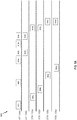
FIG. 9A schematically illustrates an exemplary communication option in a joint transmission opportunity of the joint communication system ofFIG. 7B using non-simultaneous implicit sounding. -
FIG. 9B schematically illustrates an exemplary communication option in a joint transmission opportunity of the joint communication system ofFIG. 7B using simultaneous implicit sounding. -
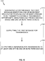
FIG. 10 depicts a method for establishing a distributed MIMO joint transmission opportunity between access points and one or more stations, in accordance with an exemplary embodiment. -
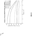
FIG. 11 depicts a graph showing PHY rate performance (e.g., path loss in PHY rates) at different levels of phase drift, in accordance with exemplary embodiments. - The detailed description and drawings are merely illustrative . The invention is defined by the appended claims.
- The word "exemplary" is used herein to mean "serving as an example, instance, or illustration." Any implementation described herein as "exemplary' is not necessarily to be construed as preferred or advantageous over other implementations. The following description is presented to enable any person skilled in the art to make and use the embodiments described herein. Details are set forth in the following description for purpose of explanation. It should be appreciated that one of ordinary skill in the art would realize that the embodiments may be practiced without the use of these specific details. In other instances, well known structures and processes are not elaborated in order not to obscure the description of the disclosed embodiments with unnecessary details. Thus, the present application is not intended to be limited by the implementations shown, but is to be accorded with the widest scope consistent with the principles and features disclosed herein.
- Wireless access network technologies may include various types of wireless local area access networks (WLANs). A WLAN may be used to interconnect nearby devices together, employing widely used access networking protocols. The various aspects described herein may apply to any communication standard, such as Wi-Fi or, more generally, any member of the IEEE 802.11 family of wireless protocols.
- In some implementations, a WLAN includes various devices which access the wireless access network. For example, there may be: access points (also referred to as "APs") and clients (also referred to as stations, or "STAs"). In general, an AP serves as a hub or a base station for the STAs in the WLAN. A STA may be a laptop computer, a personal digital assistant (PDA), a mobile phone, etc. In an example, an STA connects to an AP via a Wi-Fi (e.g., IEEE 802.11 protocol such as 802.1 1ah) compliant wireless link to obtain general connectivity to the Internet or to other wide area access networks. In some implementations an STA may also be used as an AP.
- An AP may comprise, be implemented as, or known as a NodeB, Radio Access network Controller ("RNC"), eNodeB ("eNB"), Base Station Controller ("BSC"), Base Transceiver Station ("BTS"), Base Station ("BS"), Transceiver Function ("TF"), Radio Router, Radio Transceiver, Basic Service Set ("BSS"), Extended Service Set ("ESS"), Radio Base Station ("RBS"), or some other terminology.
- A STA may also comprise, be implemented as, or known as a user terminal, an access terminal ("AT"), a subscriber station, a subscriber unit, a mobile station, a remote station, a remote terminal, a user agent, a user device, a user equipment, or some other terminology. In some implementations an access terminal may comprise a cellular telephone, a cordless telephone, a Session Initiation Protocol ("SIP") phone, a wireless local loop ("WLL") station, a personal digital assistant ("PDA"), a handheld device having wireless connection capability, or some other suitable processing device connected to a wireless modem. Accordingly, one or more aspects taught herein may be incorporated into a phone (e.g., a cellular phone or smartphone), a computer (e.g., a laptop), a portable communication device, a headset, a portable computing device (e.g., a personal data assistant), an entertainment device (e.g., a music or video device, or a satellite radio), a gaming device or system, a global positioning system device, a Node-B (Base-station), or any other suitable device that is configured to communicate via a wireless medium.
- The techniques described herein may be used for various wireless communication networks such as Code Division Multiple Access (CDMA) networks, Spatial Division Multiple Access (SDMA), Time Division Multiple Access (TDMA) networks, Frequency Division Multiple Access (FDMA) networks, Orthogonal FDMA (OFDMA) networks, Single-Carrier FDMA (SC-FDMA) networks, and so forth. The terms "networks" and "systems" are often used interchangeably. A CDMA network may implement a radio technology such as Universal Terrestrial Radio Access (UTRA), cdma2000, etc. UTRA includes Wideband-CDMA (W-CDMA) and Low Chip Rate (LCR). The cdma2000 covers IS-2000, IS-95 and IS-856 standards. An SDMA system may utilize sufficiently different directions to simultaneously transmit data belonging to multiple user terminals. A TDMA network may implement a radio technology such as Global System for Mobile Communications (GSM). An OFDMA network may implement a radio technology such as Evolved UTRA (E-UTRA), IEEE 802.11, IEEE 802.16, IEEE 802.20, Flash-OFDM, etc. UTRA, E-UTRA, and GSM are part of Universal Mobile Telecommunication System (UMTS). Long Term Evolution (LTE) is a release of UMTS that uses E-UTRA. UTRA, E-UTRA, GSM, UMTS and LTE are described in documents from an organization named "3rd Generation Partnership Project" (3GPP). The cdma2000 is described in documents from an organization named "3rd Generation Partnership Project 2" (3GPP2). These various radio technologies and standards are known in the art.
-
FIG. 1 is a diagram that illustrates a multiple-access multiple-input multiple-output (MIMO)system 100 withAP 104 andSTAs 106a-d. For simplicity, only oneAP 104 is shown inFIG. 1 . However, the multiple-access MIMO system 100 is not limited to asingle AP 104 and may include a plurality ofAPs 104. - As described above, the
AP 104 communicates with theSTAs 106a-d (also referred to herein collectively as "the STAs 106" or individually as "the STA 106"). The STA 106 may also be referred to as a base station or using some other terminology. Also as described above, the STA 106 may be fixed or mobile and may also be referred to as a user terminal, a mobile station, a wireless device, or using some other terminology. - The
AP 104 may communicate with one or more STAs 106 at any given moment viacommunication link 110. Thecommunication link 110 can be bidirectional. For example, thecommunication link 110 can include a downlink (DL) and an uplink (UL). The downlink facilitates transmission from theAP 104 to one or more of the STAs 106. The uplink facilitates transmission from one or more of the STAs 106 to theAP 104. - Alternatively, the downlink of the
communication link 110 may be referred to as a forward link or a forward channel, and the uplink of thecommunication link 110 may be referred to as a reverse link or a reverse channel. A STA 106 may in addition to, or alternatively, communicate peer-to-peer with another STA 106. - The
AP 104 may act as a base station and provide wireless communication coverage in a basic service area (BSA). TheAP 104 along with the STAs 106 associated with theAP 104 and that use theAP 104 for communication may be referred to as a basic service set (BSS) 102. It should be noted that thewireless communication system 100 may not have acentral AP 104, but rather may function as a peer-to-peer network (e.g. TDLS, WiFi-Direct) between the STAs 106. Accordingly, the functions of theAP 104 described herein may alternatively be performed by one or more of the STAs 106. - Portions of the following disclosure will describe STAs 106 capable of communicating via any of the communication networks described above (e.g., SDMA). Thus, for such aspects, the
AP 104 may be configured to communicate with both SDMA and non-SDMA STAs. This approach may conveniently allow older versions of STAs (e.g., "legacy" STAs) that do not support SDMA to remain deployed in an enterprise, extending their useful lifetime, while allowing newer SDMA STAs to be introduced as deemed appropriate. - The
MIMO system 100 may employ multiple transmit and multiple receive antennas for data transmission on the downlink and/or the uplink of thecommunication link 110. For example, theAP 104 may be equipped with N antennas and represents the multiple-input (MI) for downlink transmissions and the multiple-output (MO) for uplink transmissions. A set of K selected STAs 106 collectively represents the multiple-output for downlink transmissions and the multiple-input for uplink transmissions. For pure SDMA, it may be desired to have N ≤ K ≤ 1 if the data symbol streams for the K STAs 106 are not multiplexed in code, frequency or time by some means. K may be greater than N if the data symbol streams can be multiplexed using TDMA technique, different code channels with CDMA, disjoint sets of sub-bands with OFDM, and so on. Each selected STA 106 may transmit user-specific data to and/or receive user-specific data from theAP 104. In general, each selected STA 106 may be equipped with one or multiple antennas (i.e., M ≥1). The K selected STAs 106 can have the same number of antennas, or one or more STAs 106 may have a different number of antennas than other STAs 106 or theAP 104. - The
MIMO system 100 may be a time division duplex (TDD) system or a frequency division duplex (FDD) system. For a TDD system, the downlink and uplink share the same frequency band. For an FDD system, the downlink and uplink use different frequency bands. TheMIMO system 100 may also utilize a single carrier or multiple carriers for transmission. Each STA 106 may be equipped with a single antenna (e.g., in order to keep costs down) or multiple antennas (e.g., where the additional cost can be supported). TheMIMO system 100 may also be a TDMA system if the STAs 106 share the same frequency channel by dividing transmission/reception into different time slots, where each time slot may be assigned to a different STA 106. -
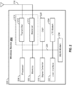
FIG. 2 illustrates various components that may be utilized in awireless device 202 that may be employed within thewireless communication system 100. Thewireless device 202 is an example of a device that may be configured to implement the various methods described herein. Thewireless device 202 may implement one or both of theAP 104 or the STA 106. - The
wireless device 202 may include an electronic hardware processor (also referred to as a "processor") 204 which controls operation of thewireless device 202. Theprocessor 204 may also be referred to as a central processing unit (CPU).Memory 206, which may include both read-only memory (ROM) and random access memory (RAM), provides instructions and data to theprocessor 204. A portion of thememory 206 may also include non-volatile random access memory (NVRAM). Theprocessor 204 may perform logical and arithmetic operations based on program instructions stored within thememory 206. The instructions in thememory 206 may be executable to implement the methods described herein. - The
processor 204 may comprise or be a component of a processing system implemented with one or more electronic hardware processors. The various illustrative logical blocks, modules, and circuits described in connection with the aspects disclosed herein may be implemented within or performed by the processing system, an integrated circuit ("IC"), an access terminal, thewireless device 202, or an access point. The processing system may be implemented using one or more ICs or may be implemented within an IC (e.g., as part of a system on a chip). An IC may comprise a general purpose processor, a digital signal processor (DSP), an application specific integrated circuit (ASIC), a field programmable gate array (FPGA) or other programmable logic device, discrete gate or transistor logic, discrete hardware components, electrical components, optical components, mechanical components, or any combination thereof designed to perform the functions described herein, and may execute codes or instructions that reside within the IC, outside of the IC, or both. A general purpose processor may be a microprocessor, but in the alternative, the processor may be any conventional processor, controller, microcontroller, or state machine. A processor may also be implemented as a combination of computing devices, e.g., a combination of a DSP and a microprocessor, a plurality of microprocessors, one or more microprocessors in conjunction with a DSP core, or any other such configuration. - The processing system may also include machine-readable media for storing software. Software shall be construed broadly to mean any type of instructions, whether referred to as software, firmware, middleware, microcode, hardware description language, or otherwise. Instructions may include code (e.g., in source code format, binary code format, executable code format, or any other suitable format of code). The instructions, when executed by the one or more processors, cause the processing system to perform the various functions described herein.
- The one or more processors may be implemented with any combination of general-purpose microprocessors, microcontrollers, digital signal processors (DSPs), field programmable gate array (FPGAs), programmable logic devices (PLDs), controllers, state machines, gated logic, discrete hardware components, dedicated hardware finite state machines, or any other suitable entities that can perform calculations or other manipulations of information.
- The
wireless device 202 may also include ahousing 208 that may include atransmitter 210 and areceiver 212 to allow transmission and reception of data between thewireless device 202 and a remote location and/or device. Thetransmitter 210 andreceiver 212 may be combined into a transceiver 214. A single or a plurality oftransceiver antennas 216 may be attached to thehousing 208 and electrically coupled to the transceiver 214. Thewireless device 202 may also include multiple transmitters, multiple receivers, and multiple transceivers as understood by a person having ordinary skill in the art. - The
wireless device 202 may also include asignal detector 218 that may be used in an effort to detect and quantify the level of signals received by the transceiver 214. Thesignal detector 218 may detect such signals as total energy, energy per subcarrier per symbol, power spectral density and other signals. - The
wireless device 202 may also include a digital signal processor (DSP) 220 for use in processing signals. In some aspects, the wireless device may also include one or more of auser interface component 222,cellular modem 234, and a wireless LAN (WLAN)modem 238. Thecellular modem 234 may provide for communication using cellular technologies, such as CDMA, GPRS, GSM, UTMS, or other cellular networking technology. TheWLAN modem 238 may provide for communications using one or more WiFi technologies, such as any of the IEEE 802.11 protocol standards. - The various components of the
wireless device 202 may be coupled together by abus 226, which may include a power bus, a control signal bus, and a status signal bus in addition to a data bus. - In certain embodiments, at least the
processor 204 and/or thebus 226 of thewireless device 202 comprises an interface. As used herein, the term interface may refer to hardware or software configured to connect two or more components of thewireless device 202 together. For example, an interface may be a part of theprocessor 204 or thebus 226 and may be configured to allow communication of information or data between two or more components of thewireless device 202. The interface may be integrated into a chip or other device. For example, in some embodiments, an interface may comprise at least a portion of thereceiver 212 configured to receive information or communications from a device such as theantenna 216 or another device. The interface (e.g., of theprocessor 204 or the bus 226) may receive information or data processed by a front end of thewireless device 202 or another device or may process information received. In some embodiments, the interface may comprise thetransmitter 210 configured to transmit or communicate information or data to theantenna 216 or another device. Thus, the interface may transmit information or data or may prepare information or data for outputting for transmission (e.g., via the bus 226). - Certain aspects of the present disclosure support transmitting the UL signal or the DL signal between one or more of the STAs 106 and the
AP 104. In some embodiments, the signals may be transmitted in a multi-user MIMO (MU-MIMO) system. Alternatively, the signals may be transmitted in a multi-user FDMA (MU-FDMA) or similar FDMA system. -
FIG. 3 shows four basic service sets (BSSs) 302a-d ofcommunication system 300. Each BSS includes anaccess point 104a-d, respectively. Eachaccess point 104a-d is associated with at least two stations within itsrespective BSS 302a-d.AP 104a is associated withSTA 106a-b.AP 104b is associated withSTA 106c-d.AP 104c is associated withSTA 106e-f.AP 104d is associated withSTAs 106g-h. AnAP 104 that is associated with a STA 106 may be referred to as a BSS AP for the STA throughout this disclosure. Similarly, anAP 104 for which there is no association with a particular STA 106 may be referred to as an OBSS AP for the STA throughout this disclosure. Associations between anAP 104 and one or more STAs 106 provides for, in part, coordination of communication between devices within the basic service set (BSS) defined by theAP 104 and its associated STAs 106. For example, devices within each BSS may exchange signals with each other. The signals may function to coordinate transmissions from therespective AP 104a-d and stations within the AP'sBSS 302a-d. - The devices shown in
FIG. 3 , including the AP's 104a-d andSTA 106a-h, also share a wireless medium. Sharing of the wireless medium is facilitated, in some aspects, via the use of carrier sense media access with collision detection (CSMA/CD). The disclosed embodiments may provide for a modified version of CSMA/CD that provides for an increase in an ability for theBSSs 302a-d to communicate simultaneously when compared to known systems. - The
stations 106a-h within theBSSs 302a-d may have different abilities to receive transmissions from their associated AP based, at least in part, on their position relative to theother APs 104 and/or STAs 106 outside their respective BSS (OBSS). For example, because thestations OBSS APs 104, these stations may have an ability to receive transmissions from theirrespective BSS AP 104 even when anOBSS AP 104 or STA 106 is transmitting. Stations having such receive characteristics may be referred to as reuse STAs throughout this disclosure. Reuse STAs may have sufficient signal to noise ratios (SINRs) withOBSS APs 104 that they may communicate with other STAs 106 and/orAPs 104 without having to be nulled. - In contrast,
STAs OBSS AP 104. Thus, these stations may have less ability to receive transmissions from theirBSS AP 104 during transmissions fromOBSS APs 104 and/or OBSS STAs 106 due to interference. Stations having such receive characteristics may be referred to as non-reuse or edge STAs 106 throughout this disclosure. - Non-reuse STAs may have insufficient signal to noise ratios (SINRs) with
OBSS APs 104 requiring that they be nulled in order to communicate with other STAs 106 and/orAPs 104 while communications are occurring involving theOBSS APs 104. In some aspects, the disclosed methods and systems may provide for an improved ability for the non-reuse STAs 106 to communicate concurrently while other OBSS devices, such as other APs and STAs, are also communicating on the wireless medium. -
FIG. 4 shows threeexemplary approaches 400 to arbitrating the wireless medium with thecommunication system 300 ofFIG. 3 .Approach 405 utilizes carrier sense media access (CSMA) to perform single BSS multi-user transmissions. For example, each oftransmissions 420a-d may be performed by theBSSs FIG. 3 respectively. The use of traditional CSMA inapproach 405 causes the medium to be utilized by only oneBSS 302 at any point in time. -
Approach 410 utilizes coordinated beamforming (COBF). With the coordinatedbeamforming approach 410, theAPs 104a-d may coordinate transmissions between theirrespective BSSs 302a-d. In some aspects, this coordination may be performed over the wireless medium, or in some aspects, over a back-haul network. In these aspects, the coordination traffic over the backhaul network provided for improved utilization of the wireless medium. - With this approach, reuse STAs 106a, 106d, 106e, and 106h for different BSSs may be scheduled to transmit or receive data concurrently. For example, a relative strength of a communication channel between
STA 106a andAP 104a may allow these two devices to exchange data simultaneously with communication with OBSS devices, such as, for example,AP 104b andSTA 106d. - In addition,
approach 410 allows for non-reuse STAs 106b, 106c, 106f, and 106g to be scheduled for transmission concurrently with OBSS devices. For example,STA 106b, which is withinBSS 302a, may be scheduled to communicate simultaneous with communication betweenAP 104d andSTA 106h ofBSS 302d. Such simultaneous communication between a non-reuse STA (such asSTA 106b) and, for example,AP 104d may be facilitated by schedulingAP 104d to transmit a signal toSTA 106b simultaneous withAP 104d's transmission toSTA 106h. For example,AP 104d may transmit a null signal for dominant interfering signals toSTA 106b. Thus, while transmitting a first signal toSTA 106h,AP 104d may simultaneously transmit a signal nulling the first signal toSTA 106b. Such simultaneous transmission by theAP 104d may be provided by selecting individual antenna(s) of a plurality of antennas provided byAP 104d for each of the transmissions. Such nulling may create reuse opportunities for otherwise non-reuse STAs. COBF may operate in both DL and UL directions with theAPs 104 nulling respective frequencies. - Approach 415 shows an exemplary joint multi-user communication or a distributed MIMO communication across
APs 104a-d within theBSSs 302a-d ofFigure 3 . With thisjoint MIMO approach 415,multiple APs 104, such as a cluster ofAPs 104a-d, may service N 1-SS STAs simultaneously, where N is ~3/4 of a total number of antennas across all APs within the cluster. - Distributed MIMO communications may coordinate a collection of antennas across the
multiple APs 104 within a cluster to transmit to stations 106 within the cluster. Thus, while traditional MIMO methods allocate transmit antennas within a single BSS to stations within the BSS, distributed MIMO provides for allocation of transmit antennas outside a BSS to facilitate communications with stations within the BSS. - In a distributed MIMO communication, a station in one BSS may communicate with one or more access points in another, different BSS. Thus, for example,
station 106a ofBSS 302a ofFIG. 3 may communicate withaccess point 104d, which is inBSS 302d. This communication may occur simultaneously with communication betweenSTA 106a andAP 104a, the BSS AP of theSTA 106a. In some aspects of an uplink distributed MIMO communication, theSTA 106a may conduct one or more uplink communications toAP 104a simultaneously withAP 104d. Alternatively, a downlink distributed MIMO communication may includeAP 104a transmitting data toSTA 106a simultaneously with a transmission fromAP 104d toSTA 106a. - Thus, one or more of the distributed embodiments may utilize MIMO in the form of Cooperative Multipoint (CoMP, also referred to as e.g. Network MIMO (N-MIMO), Distributed MIMO (D-MIMO), or Cooperative MIMO (Co-MIMO), etc) transmission, in which multiple access points maintaining multiple corresponding basic service sets, can conduct respective cooperative or joint communications with one or more STAs 106. CoMP communication between STAs and APs can utilize for example, a joint processing scheme, in which an access point associated with a station (a BSS AP) and an access point that is not associated with a station (a OBSS AP) cooperate to engage in transmitting downlink data to the STA and/or jointly receiving uplink data from the STA. Additionally or alternatively, CoMP communication between an STA and multiple access points can utilize coordinated beamforming, in which a BSS AP and an OBSS AP can cooperate such that an OBSS AP forms a spatial beam for transmission away from the BSS AP and, in some aspects, at least a portion of its associated stations, thereby enabling the BSS AP to communicate with one or more of its associated stations with reduced interference.
- To facilitate the coordinated
beamforming approach 410 or thejoint MIMO approach 415, an understanding of channel conditions between an access point and OBSS devices may provide for greater wireless communication efficiency. -
FIG. 5 schematically illustrates a plurality of basic service sets (BSSs) 302 of an exemplary distributed MIMO wireless communication system. Each hexagon ofFIG. 5 represents an access point and associated stations, collectively referred to as a basic service set (BSS) 302 such as described with respect toFIG. 3 . Theindividual BSSs 302 are grouped into clusters, (C1), (C2), and (C3) in accordance with certain embodiments described herein. - In the example schematically illustrated by
FIG. 5 , a first cluster (C1) comprises fourBSSs 302, a second cluster (C2) comprises fourBSSs 302, and a third cluster (C3) comprises fourBSSs 302. In certain other embodiments, a cluster can comprise 2, 3, 4, 5, or any numbers ofBSSs 302 and a wireless communication system can comprise one or more clusters (e.g., 2, 3, 4, 5 or other numbers of clusters). - In at least some of the disclosed aspects, two or more of the
APs 104a-d fromFigure 3 may negotiate to form a cluster or a portion of a cluster, such as clusters (C1), (C2), and (C3) illustrated inFIG. 5 . In certain embodiments, the cluster (C1) comprisesBSSs 302a-d. In other aspects, cluster configurations may be defined via manual configuration. For example, eachAP 104 may maintain configuration parameters indicating whether theAP 104 is part of one or more clusters (C1), (C2), and (C3), and if so, a cluster identifier for the cluster (C1), (C2), and (C3). In some aspects, the configuration may also indicate whether theAP 104 is acontroller 510 for the cluster (C1), (C2), and (C3). For example, in certain embodiments, theAP 104a of theBSS 302a of cluster (C1) is configured as thecontroller 510 of cluster (C1). - In some of the embodiments disclosed herein, the
controller 510 may take on functions that differ fromAPs 104 that are part of the cluster (C1) but are not thecontroller 510. Thus, in some aspects, two or more ofAPs 104a-d may be included in the same cluster (C1), (C2), and (C3). STAs 106 associated with thoseAPs 104 may also be considered to be included in or part of the cluster (C1), (C2), and (C3) of their associatedAP 104. Therefore, in some aspects theSTAs 106a-h illustrated above may be part of the same cluster (C1), (C2), and (C3). - The cluster (C1), (C2), and (C3) of
APs 104 may coordinate transmissions between themselves and their associatedAPs 104. In some aspects, the cluster (C1), (C2), and (C3) may be identified via a cluster identifier value or number that uniquely identifies the group ofAPs 104 comprising the cluster (C1), (C2), and (C3). In some aspects, during association of a STA 106 with any of theAPs 104 in the cluster (C1), (C2), and (C3), the cluster identifier value is transmitted to the STA 106 during association, for example, in an association response message. The STA 106 may then utilize the cluster identifier value to coordinate communications within the cluster (C1), (C2), and (C3). For example, one or more messages transmitted over the wireless network may include the cluster identifier value, which a receiving STA 106 may use to determine whether or not the message is addressed to the STA 106. - In some embodiments, the cluster (C1), (C2), and (C3) of
APs 104 may also utilize various methods to identify STAs 106 within the cluster (C1), (C2), and (C3). For example, as known methods of generating association identifiers (AIDs) may not provide uniqueness acrossAPs 104, in some aspects, media access control (MAC) addresses may be utilized to identify STAs 106 where appropriate. For example, known messages including user info fields that utilize association identifiers to identify STAs 106 may be modified to contain data derived from station MAC addresses in the disclosed embodiments. Alternatively, methods of generating association identifiers may be modified to ensure uniqueness within a cluster (C1), (C2), and (C3) ofAPs 104. For example, a portion of the association identifier may uniquely identify anAP 104 within the cluster (C1), (C2), and (C3). Stations associated with thataccess point 104 would be assigned association identifiers including the unique identification. This provides unique association identifiers across access points within a cluster (C1), (C2), and (C3). In some other aspects, an association identifier within a cluster (C1), (C2), and (C3) may include the cluster identifier. This may provide for uniqueness across clusters to facilitate future cross-cluster coordination of communication. - In certain embodiments, to perform distributed MIMO communications, devices within two or more BSSs 302 of a cluster (C1), (C2), and (C3) may transmit over a single channel simultaneously (e.g., transmit data from a plurality of
APs 104 of the BSS simultaneously via the single channel, or transmit data from a plurality of stations in different BSSs simultaneously to a single AP). In some aspects, a centralized scheduler may coordinate transmissions across the clusters (C1), (C2), and (C3). For example, coordination may include selecting which devices will transmit simultaneously from multiple BSSs to perform a joint MIMO communication. - Under European Telecommunications Standard Institute (ETSI) regulations, wireless communication systems are generally required to utilize clear channel assessment (CCA) or listen-before-talk (LBT) before allowing access to the wireless network. Generally, two different access modes are allowed in such wireless communication systems: "frame-based" access mode and "load-based" access mode. To utilize coordinated access in an unlicensed spectrum, it is generally desirable for a device on the wireless network to use a safe or allowed mechanism for ignoring same-network deferral while honoring LBT toward other devices on the wireless network. A similar issue arises with licensed assisted access (LAA) systems, which are bound to a fixed frame structure. However, in wireless communication systems which are not bound to a fixed frame structure (e.g., WiFi), a more flexible and/or efficient solution may be used. Certain embodiments described herein advantageously provide a way to enable reuse (e.g., stations able to serve simultaneously without having to be nulled) by synchronizing the physical layer convergence procedure (PLCP) protocol data unit (PPDU) start time, which may be seen as a forced collision. In certain such embodiments, the timing scheme is configured so that energy detect (ED) or power detect (PD) operations do not trigger within the same wireless network at the start of a frame (e.g., having a standard that defines requirements for CCA timing and synchronization).
-
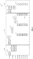
FIG. 6 schematically illustrates an exemplary communication option in a downlink coordinated beamforming (COBF)transmission opportunity 600 of the distributed MIMOwireless communication system 400 ofFIG. 4 . Thetransmission opportunity 600 may comprise three different phases during which one ormore APs 104 may communicate with each other and with corresponding STAs 106 of theirBSSs 302a-d. Each of theAPs 104 of theBSSs 302a-d may apply for or request control of transmissions within thewireless communication system 400. A winningAP 104 may then have control over thetransmission opportunity 600 as shown inFIG. 6 . In some embodiments, the winning AP may beAP 104a. After theAP 104a wins control of thetransmission opportunity 600, theAP 104a may initiate DL COBF transmissions in the obtainedtransmission opportunity 600 over three phases. While thetransmission opportunity 600 relates to DL COBF transmissions, the discussions herein may pertain to any type of communication that may occur in transmission opportunities. - A first phase 602 may correspond to a candidate STA identification period. During the first phase 602, the winning AP (e.g.,
AP 104a) may poll OBSS APs 104 (e.g., the APs forother BSSs 302 than theAP 104a) for their candidate STAs 106 having buffered DL data. Based on the received information and/or identifications, the winning AP,AP 104a, may determine which STAs 106 are to be scheduled for communication during thetransmission opportunity 600. Asecond phase 604 may correspond to a multi-BSS 302 sounding period. During thesecond phase 604, the winningAP 104a may coordinate a multi-BSS 302 sounding during which each collaborating AP 104 (e.g., each of theAPs 104 that intend to communicate during the transmission opportunity 600) identifies scheduled BSS STAs 106 and OBSS non-reuse STAs 106. For example, this may comprise signal strength or other metrics (e.g., beacon RSSI of APs 104) for communications betweenAPs 104 and STAs 106. A third phase 606 may correspond to a DL COBF transmission period. During the third phase 606, each of the collaboratingAPs 104 may simultaneously begin DL COBF transmissions for their scheduled BSS STAs 106 while nulling OBSS non-reuse STAs 106. For example, with reference toFIG. 3 ,AP 104c may transmit DL COBF transmissions toSTAs APs second phase 604 may not be required if theAPs 104 already have knowledge of candidate STAs 106 having DL data buffered and/or when details of the metrics of communications betweenAPs 104 and STAs 106 are known. - During the first phase 602, the
AP 104a may transmit a trigger message or frame 610 directed to OBSS APs 104 (e.g.,APs 104b-104d). In some embodiments, theAP 104a may transmit thetrigger frame 610 to only selectedAPs 104. Thetrigger frame 610 may be transmitted toOBSS APs 104 to determine the candidate STAs 106 that exist for each of theAPs 104 that receive thetrigger frame 610. The candidate STAs 106 may comprise STAs to which data will be transmitted during thetransmission opportunity 600. In thetrigger frame 610, theAP 104a may indicate which one ormore OBSS APs 104 are selected for participation in the transmission opportunity 600 (e.g.,AP 104b andAP 104c). In some embodiments, thetrigger frame 610 also includes identification of non-reuse STAs 106 of theAP 104a BSS 302a (e.g.,STA 106b). In some embodiments, thetrigger frame 610 also includes identification of dimensions ofAP 104a that remain after scheduling the non-reuse and reuse STAs of theAP 104a. - Also during the first phase 602, the
APs AP 104a in the form of high efficiency trigger based PPDUs. In some embodiments, these reports 611 indicate candidate non-reuse STAs 106 for each of theAPs APs AP 104a. - After receiving the reports 611, the
AP 104a may determine a schedule for the STAs 106 that will receive transmissions during thetransmission opportunity 600. In some embodiments, theAP 104a may first schedule non-reuse and reuse STAs 106 that belong to theBSS 302a with theAP 104a. Once the STAs 106 of theBSS 302a are scheduled, theAP 104a may sequentially add OBSS non-reuse STAs 106 if a total required dimension of scheduled STAs 106 is less than a total dimension of theAPs 104a-c. This may assume that each non-reuse STA costs one (1) dimension for eachAP 104a-c. - During the
second phase 604, theAP 104a may transmit a null data packet announcement (NDPA) and scheduling frame along with a null data packet and trigger frame in a communication 615 to the selectedOBSS APs 104b-c. The NDPA and scheduling frame of the communication 615 may indicate scheduled non-reuse STAs 106 of allAPs 104a-c and NDPA start times for eachOBSS AP 104b-c. In some embodiments, the communication 615 may be transmitted to the STAs 106 and the STAs 106 may each transmit a beamforming report (BFRP) frame 616 to theAP 104a in response to the communication 615. Also during thesecond phase 604, theAP 104b may transmit a NDPA, a null data packet (NDP), and a trigger frame in acommunication 617. Similarly, theAP 104c may transmit a NDPA, a NDP, and a trigger frame in a communication 619. Thecommunications 617 and 619 may allow eachAP BSS 302 of theAP 104. Each of the STAs 106 may respond with BFRP frames 618 to thecommunication 617 and BFRP frames 620 to the communication 619. - During the third phase 606, the
AP 104a sends atrigger frame 625 toOBSS APs trigger frame 625 may indicate an initiation of DL COBF transmissions. Once thetrigger frame 625 is transmitted by theAP 104a and once theOBSS APs trigger frame 625, each of theAPs 104a-c may transmit their DL COBF transmissions 626 to their respective scheduled non-reuse STAs 106 while simultaneously nulling the OBSS non-reuse STAs 106. In some embodiments, eachAP 104a-c may add its reuse STAs 106 in or to the DL COBF transmissions 626 if theAP 104 has available dimensions. In some embodiments, the resource units for UL block acknowledgements 627 may be indicated in the NDPA and scheduling frames of one or more of thecommunications 615, 617, and/or 619. -
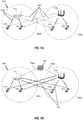
FIG. 7A schematically illustrates an example multiple-access MIMOwireless communication system 700 in which coordinated beamforming (COBF) may be used by access points (APs) 104a-b to communicate with stations (STAs) 106a-d belonging to corresponding basic service sets (BSSs) 302a-b, in accordance with certain embodiments described herein. TheAPs 104, STAs 106, andBSSs 302 illustrated inFIG. 7A have the same functionality as theAPs 104, STAs 106, andBSSs 302 illustrated inFIG. 3 , they are not associated with each other as is illustrated inFIG. 3 but instead are associated as illustrated inFIG. 7A to simplify describingFIG. 7A . - The
APs 104a-b (also referred to herein collectively as "theAPs 104" or individually as "theAP 104") communicate with theSTAs 106a-d (also referred to herein collectively as "the STAs 106" or individually as "the STA 106"). TheAP 104 may also be referred to as a base station or using some other terminology. Also as described above, the STA 106 may be fixed or mobile and may also be referred to as a user terminal, a mobile station, a wireless device, or using some other terminology. - The
APs 104a-b may act as base stations and provide wireless communication coverage in corresponding basic service areas (BSAs). TheAP 104a along with theSTAs 106a-b associated with theAP 104a and that use theAP 104a for communication may be referred to as a basic service set (BSS) 302a. TheAP 104b along with theSTAs 106c-d associated with theAP 104b and that use theAP 104b for communication may be referred to as a basic service set (BSS) 302b. It should be noted that thewireless communication system 700 may not have acentral AP 104, but rather may function as a peer-to-peer network (e.g. TDLS, WiFi-Direct) between the STAs 106. Accordingly, the functions of theAPs 104a-b described herein may alternatively be performed by one or more of the STAs 106. - The
APs 104a-b may communicate with one or more STAs 106 at any given moment via communications links 110. Oneexemplary communication link 110a may facilitate transmission between theAP 104a and one or more of its associated STAs 106a and 106b of theBSS 302a. As shown inFIG. 7A , data transmissions to BSS STAs 106 are shown as solid lines between theAP 104a andSTAs 106a-b andAP 104b andSTAs 106c-d, while steerednull transmissions 705 to OBSS STAs are shown as dashed lines between theAP 104a andSTAs 106c-d andAP 104b andSTAs 106a-b. - Accordingly, each
AP 104a-b may use coordinated beamforming to simultaneously communicate with corresponding BSS (or associated) STAs 106a-d while nulling OBSS (or non-associated) STAs 106a-d. The coordinated beamforming may allow theAPs 104a-b to simultaneously transmit data to respective BSS STAs 106 without causing interfering with the OBSS STAs 106. Therefore, in thesystem 700, transmissions for a particular STA 106 are only transmitted from asingle AP 104 while the STA 106 only receives nulls fromOBSS APs 104. -
FIG. 7B schematically illustrates an example joint transmission multiple-access MIMOwireless communication system 750 in which COBF may be used byAPs 104 to communicate with STAs 106 belonging to their own andother BSSs 302, in accordance with certain embodiments described herein. Similar components and communications as described herein in relation toFIG. 7A will not be described again here. - As described in relation to
FIG. 7A , theAPs 104a-b may communicate with one or more STAs 106 at any given moment via communications links 110. However, contrary to theAPs 104a-b ofFIG. 7A , theAPs 104a-b may both be configured to transmit data to a single STA 106 (e.g.,STA 106a). As shown inFIG. 7B , data transmissions to STAs 106 are shown as solid lines between theAPs 104a-b and all of theSTAs 106a-d. As opposed to thecommunications links 110 shown inFIG. 7A, FIG. 7B includes no steerednull transmissions 705 to OBSS STAs 106 from APs 104 (e.g., no dashed lines between either of theAPs 104a-d and any of theSTAs 106c-d). Instead all of thecommunication links 110 shown, including the identifiedcommunication links 110 fromAP 104b toSTA 106c andSTA 106b, are data transmissions between theAPs 104a-b and theSTAs 106a-d. - When each of the
APs 104a-b are able to transmit data to each STA 106, the data to be transmitted to each STA 106 may be made available to each of theAPs 104a-b so that either of theAPs 104a-b may transmit any portion(s) of the data to the STA 106. Additionally, coordinating the data transmission from theAPs 104a-b and the STA 106 may be more involved than when only asingle AP 104a-b transmits data to the STA 106. - For example, when
multiple APs 104 are each transmitting a portion of the data to the STA 106, the data transmissions of eachAP 104 must be coordinated with theother APs 104 to ensure that data transmissions are not duplicated, that all data is transmitted, that data transmissions do not overlap each other, etc. In some embodiments, a master access point (AP) 104 (e.g.,AP 104a) or an external controller (e.g., central controller 755) controls and/or coordinates the communications between theAPs 104a-b and the STA 106. The central controller 755 (ormaster AP 104a) may establish a backhaul network between itself and all communicatingAPs 104. The backhaul network may comprisebackhaul links master AP 104a) and the communicating APs 104 (e.g.,APs master AP 104a manages the jointtransmission communication system 750, the remainingAPs 104 of the jointtransmission communication system 750 may be slave access points (APs) 104. When thecentral controller 755 manages the jointtransmission communication system 750, then all of theAPs 104 of the jointtransmission communication system 750 may beslave APs 104. In some embodiments, thecentral controller 755 implemented in the jointtransmission communication system 750 may utilize a precoder over an array of antennas (e.g., thetransmitter antennas 216 of all associatedAPs 104, e.g.,APs 104a-b ofFIG. 7B ). The precoder and thecentral controller 755 may coordinate timing synchronization between theAPs 104a-b and the correspondingtransmitter antennas 216. The precoder may ensure that transmissions fromAPs 104 to a STA 106 will not be too strong at other STAs 106. The coordinated timing synchronization may be important whendifferent APs 104a-b are jointly transmitting data transmissions to a single, shared, or multiple STAs 106. - In some embodiments, the
central controller 755 coordinating timing synchronization between theAPs 104 and the STA 106 may also control or manage synchronization between theAPs 104. TheAPs 104 participating in transmitting data to the STA 106 may participate in joint transmissions. In certain embodiments to enable and maintain efficient and complete joint transmissions between theAPs 104 and the STA 106, the phase deltas across theAPs 104 are tracked and/or synchronized. In some embodiments, the phase of anAP 104 can be thought to be equal to or related to a local oscillator ("LO") phase (measured in degrees or radians). If a frequency of the LO is constant (e.g., no jitters), then the phase of the LO changes linearly with time. This may occur for everyAP 104. However, ifdifferent APs 104 have slightly different frequencies at their LOs, then the phase of the APs 104s may diverge with time. Additionally, the effective phase ofAPs 104 may jitter due to phase noise, which may be different for eachAP 104. Moreover, any timing offsets between oneAP 104 and a STA 106 may appear as a phase ramp in frequency in the channel from thatAP 104 to the STA 106. - In certain embodiments, there are different phase-ramps corresponding to
different APs 104 at the same STA 106. Such an arrangement is acceptable when the difference between the phase ramps stays constant. In contrast, a change in relative phase of theAPs 104 beyond a certain amount can result in the precoding no longer being valid. The phase of anAP 104 may refer to a power level of transmission by theAP 104. A change in "relative" phase betweenAPs 104 may cause problems when what is being measure as a relative phase during a sounding period is different from the relative phase at a time of actual transmission. Since precoding for the transmission was done based on what was measured during the sounding period, the precoding may not remain valid if the relative phase during the transmission drifts beyond a certain limit or threshold. The relative phase drift may result in the strength of a signal and/or transmission meant for one user being high enough at a second user to cause interference at the second user. When precoding is working well, each user may only see signals and/or transmissions meant for that user while signals and/or transmissions meant for other users are weak enough to not cause interference for the user. Thus, it may be desirable to maintain phases (or phase deltas) between devices within given amounts or thresholds. - When managing joint transmissions by the
APs 104, the phase deltas (e.g., differences) between the participating APs 104 (e.g., theAPs 104 that are transmitting data to the STA 106) may cause the issues in the joint transmissions described herein. Various benefits may be realized by maintaining phase deltas across theAPs 104. By maintaining the phase deltas, the transmissions may not cause interference between receiving devices. Accordingly, when the phase drift exceeds a threshold amount, the devices (e.g., theAPs - In some embodiments, the phase deltas of the
APs 104 participating in the joint transmissions may be maintained at constant levels during the sounding and transmission periods (e.g., the sounding period and the transmission period described in relation toFIG. 6 ) of distributed MIMO sessions. Alternatively, or additionally, the phase deltas of theAPs 104 participating in the joint transmission may be maintained at approximately a constant level or some other level through periodic phase synchronizations. If the phase deltas of theAPs 104 begin to change from the initial phase delta (e.g., the phase delta begins to increase or decrease), synchronization may be used to "correct" the phase delta (e.g., phase correction) to the initial value or a value substantially similar to the initial value. - In joint transmissions, the
collective antennas 216 of theAPs 104 may mimic or operate as a single antenna array. From the perspective of the receiving STA 106, theantennas 216 of theAPs 104 may be treated or appear as the single antenna array. However, phase drift or phase delta drifts (hereinafter "phase drifts") may disrupt the "single antenna array" operation or view of the collective antennas of theAPs 104. Specifically, while phase drifts may occur in general operation of theAPs 104 and theirantennas 216, these phase drifts may cause the phase differences of theAPs 104 to change between the sounding and data transmission period. As the phase drifts cause phase differences of theAPs 104 between the sounding and the data transmission periods, the joint transmissions by theAPs 104 may be adversely impacted by potentially introducing cross user or cross stream leakage and increasing interference betweenAPs 104 and STAs 106. - Accordingly, such phase drift may desirably be minimized or avoided by synchronizing phases and/or phase drifts and/or by avoiding protocols that may lead to an introduction of relative phase offsets across the
APs 104. In some embodiments, one or more phase drifts may be detected by thecentral controller 755 or a similar component configured to monitor and/or track phase drift and/or phase delta drift between theAPs 104. If a phase drift is detected, then thecentral controller 755 may synchronize the phases of one or more of the "drifting"APs 104. Such synchronization may occur during one or more of the sounding period and the data distribution period. In some embodiments, the synchronization may occur during the data distribution period, for example, when the data distribution period is of an extended duration (e.g., more than a typical data distribution period). Advantageously, phase drifts across STAs 106 do not impact the joint transmissions described herein. - In the joint
transmission communication system 750, the backhaul or similar communication network shown withbackhaul links 755a-b may exist between theAPs 104 participating in the joint transmission. The backhaul links 755a-b may provide for time and/or frequency synchronization between theAPs 104. For example, thebackhaul links 755a-b may allow theAPs 104 to coordinate their clocks and frequencies over which theAPs 104 will communicate. In some implementations, thebackhaul links 755a-b may also be used to share the data to be transmitted and any data received with all of theAPs 104. In some instances, phase synchronization may be performed via thebackhaul links 755a-b as well. - Phase synchronization signals or transmissions may be used to maintain the phase drift or drift of phase difference between
APs 104 to be within a few degrees during the various periods of a communication window or transmission opportunity. The phase synchronization signals may be transmitted by themaster AP 104 or thecentral controller 755. - In certain embodiments when the
APs 104 have a frequency offset of 10Hz between each other, a 1ms time period may result in a 3.6 degree shift in the phase difference between theAPs 104. In some embodiments, the 3.6 degree phase difference shift may be high enough to warrant phase synchronization at approximately 1ms intervals. Accordingly, phase synchronization may be implemented at the beginning of each joint transmission. In some embodiments, depending on a length of the joint transmission, the phase synchronization may be performed during the joint transmission itself. For example, amaster AP 104 may transmit a synchronization frame (e.g., sync frame) to achieve the phase synchronization across theAPs 104. - In some embodiments, the
APs 104 that utilize automatic gain control (AGC) may experience increased phase difference drifts. For example, different gain states that result from the AGC may result in different amplitudes and phases to correspond with the different gain states. Thus, as the gain states for theAPs 104 change, the corresponding amplitudes and phases may change. Thus, in one situation, when aslave AP 104 using AGC attempts to synchronize with the master AP 104 (or the central controller 755), if the gain state of theslave AP 104 is different when the phase synchronization signal is received as compared to the gain state during a previous reference or reference signal, then the phase synchronization may not achieve the desired tight phase drift synchronization. In another situation, channel measurements by the STA 106 may have different gain states fordifferent APs 104. - The joint
transmission communication system 750 may utilize different sounding and transmission period requirements and communications as compared to the sounding and transmission periods shown inFIG. 6 for thesystem 700. For example, theantennas 216 for theAPs 104 of thesystem 700 are sounded in separate NDP/NDPA transmissions (see, for example,communications 615, 617, and 619 ofFIG. 6 ). Each NDP transmission may have its own phase and receipt AGC setting and may be communicated at different times for each of theAPs 104. Accordingly, it may be difficult for thecentral controller 755 to utilize sounding measurements resulting from different NDPs together. Additionally, relative timing among theAP 104 antennas may not be constant across the sounding periods and the transmission periods. - For the joint
transmission communication system 750, the participatingAPs 104 may be sounded together (e.g., at the same time). For example, the NDP transmissions for each of the participatingAPs 104 may be transmitted at the same time. When explicit sounding is used (e.g., when the sounding information is determined by the STA 106 in response to NDPs transmitted by the APs 104), a joint NDP may be transmitted by theAPs 104. The joint NDP may be transmitted by theAPs 104 to all of the STAs 106, as will be described in more detail herein. Another difference between thejoint transmission system 750 and thecommunication system 700 is that in thejoint transmission system 750, feedback received from the STA 106 in response to the NDP transmissions may be received from the STA 106 by any of theAPs 104, which can disseminate the received feedback to theother APs 104 of thesystem 750. In thecommunication system 700, eachAP 104 receives feedback signals from the STA 106 individually with no sharing of feedback information between theAPs 104. In some embodiments, the sharing of feedback (and potentially other information) may be accomplished via thebackhaul links 755a-b. -
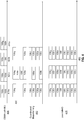
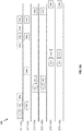
FIGs. 8A-8B schematically illustrate an exemplary communication option in ajoint transmission opportunity joint communication system 750 ofFIG. 7B , with non-simultaneous STA feedback 808 (FIG. 8A ) and simultaneous STA feedback 808 (FIG. 8B ). TheAP 104a may be associated with theSTAs 106a-b. TheAP 104b may be associated with theSTAs 106c-d. Thejoint transmission opportunity 800 may depict two phases corresponding to a sounding period and a transmission period. Group formation may be achieved via thebackhaul links 755a-b. Group formation may correspond to identifying whichAPs 104 and STAs 106 will participate in thejoint transmission opportunity 800. Thejoint transmission system 750 may utilize master andslave APs 104 or thecentral controller 755 and controlled (or slave)APs 104. Furthermore, thejoint transmission system 750 may utilize either explicit or implicit sounding. As described above, explicit sounding occurs when theAPs 104 transmit NDPs to which the STAs 106 respond with feedback measurements. Implicit sounding occurs when the STAs 106 send a communication to theAPs 104 and theAPs 104 generate measurements based on the received communication. - The
joint transmission opportunity 800 may begin with themaster AP 104a transmitting anNDPA message 802. This may coincide with the beginning of the sounding period of thejoint transmission opportunity 800. As utilized herein, the controller (e.g., thecentral controller 755 ofFIG. 7B ) and themaster AP 104a may perform functions, and may be referenced, interchangeably. TheAP 104a that transmits theNDPA 802 may be designated as themaster AP 104a and the remainingAPs 104b may be designated asslave APs 104b. Theslave APs 104b may be responsible for synchronizing with themaster AP 104a, where synchronizing includes synchronizing one or more of time (e.g., clocks), frequency, and phase drift. As described herein, theNDPA 802 may serve to announce a subsequent NDP transmission and may serve as a synchronization message too. - The
NDPA 802 may identify all STAs 106 that will be receiving information via joint transmissions and a number of streams being allocated to each STA 106. In some embodiments, when serving as the synchronization message, theNDPA 802 may include necessary information to synchronize the phase drift between theslave APs 104b. For example, theNDPA 802 may let the slave APs 104 (e.g.,AP 104b) synchronize their frequencies to the master AP 104 (e.g.,AP 104a) frequency. Additionally, theNDPA 802 may provide a reference or reference phase to the slave APs 104 (e.g.,AP 104b). - The sounding period may continue with the
master AP 104 and participatingslave APs 104 each transmittingNDP transmission NDP transmissions APs 104. Following theNDP transmissions master AP 104a may transmit anoptional trigger frame 806a to indicate to the STAs 106 when the STAs 106 should transmit their feedback. - Following the
trigger frame 806a, theSTAs APs 104. In some embodiments, the STAs 106 may transmit the feedback using uplink MU-MIMO transmissions 808. For example, theSTA 106a may transmit feedback viatransmissions 808a-808b while theSTA 106b may transmit feedback viatransmissions 808c-808d. In some embodiments, thetransmissions 808a-808b may be combined into a single PPDU sent to themaster AP 104a even though thetransmissions 808a-808b include feedback from two separate NDPs from themaster AP 104a and theslave AP 104b. - Similarly, the
transmissions 808c-d may be combined into a single PPDU sent to themaster AP 104a. Additionally, theSTA 106c may transmit feedback viatransmissions 808e-808f while theSTA 106d may transmit feedback viatransmissions 808g-808h following a secondoptional trigger frame 806b. The feedback transmitted from STAs 106 may be sent to theAP 104 that sends the trigger because the responding STAs 106 may synchronize to thatAP 104 via the trigger and possibly get power and rate control information in the trigger frame 806 about that feedback transmission. - In some embodiments, the
transmissions 808e-808f and thetransmissions 808g-h are combined into a single PPDU sent to theslave AP 104b. In some embodiments, the receivingAP 104 of thetransmissions 808a-808h may be arbitrary. In some embodiments, the receivingAP 104 may be determined based on theBSS 302 to which the STAs 106 belong (e.g., based on theAP 104 with which the STA 106 is associated). Once theAPs 104 receive thefeedback transmissions 808a-h from their corresponding STAs 106, theAPs 104 may share or disseminate the feedback received over thebackhaul links other APs 104. Thus, the feedback information need only be received by asingle AP 104 for all of theAPs 104 to obtain and utilize the feedback information. - As shown in
FIG. 8A , thefeedback transmissions 808a-808d and 808e-h from theSTAs 106a-b andSTAs 106c-d, respectively, may not be received simultaneously. These feedback transmissions may be received separately because theAPs 104 may be unable to receive feedback from all the STAs 106 simultaneously due to lack of joint MIMO reception in the uplink. This may be a result of a quantity of users and/or streams being supported by theAPs 104 during data transmission. For example, a quantity of antennas of theAPs 104 being used for j oint transmission may limit a quantity of antennas available for reception of feedback. However, if theAPs 104 support joint reception (e.g., where the receive antennas of all theAPs 104 operate as a receive antenna array) and the received measurements (e.g., feedback transmissions 808) from the STAs 106 can be processed together, then the STAs 106 may transmit their feedback transmission simultaneously, as shown inFIG. 8B . - As seen from comparing
FIGs. 8A and8B , by allowing simultaneous feedback from all STAs 106, the duration of the entire joint transmission opportunity may be reduced or additional time may be dedicated to data transmission. However, a natural division may be for feedback to be communicated according toBSS 302 associations and then have the feedback shared via thebackhaul links APs 104 may conclude the sounding period. - The transmission period may include
optional trigger frames 810a-b for phase synchronizing. For example, the trigger frames 810a-b may include similar phase information as theNDPA 802 described above. For example, the trigger frames 810a-b may include a reference or reference phase to theslave APs 104 based on a phase of themaster AP 104. - In some embodiments, the NDPA may plan for a certain number of streams and a certain group or grouping of STAs 106. However, once the
AP 104 receives channel state information ("CSI") from the STAs 106, themaster AP 104 may make changes to the plan. For example, themaster AP 104 change how many streams an STA 106 receives or may choose to exclude one or more STAs 106 from the joint transmission opportunity based on poor channel conditions or high correlations between channels of STAs 106. - In response to the trigger frames 810a-b, the
APs 104 that are participating in the joint transmission may synchronize their phase based on the reference or reference phase and then may transmit their data, e.g., via a distributedMIMO transmission 812a-b. As shown, theAPs 104a-b transmit data during theMIMO transmissions 812a-b simultaneously. There may be multiple instances of the optional trigger frames 810 and MIMO transmissions 812, with two instances shown inFIGs. 8A and8B . The transmission period may be concluded withacknowledgement messages 816a-d being transmitted from each STA 106. In some embodiments, theacknowledgement messages 816a-d may be transmitted simultaneously or in groups according to associatedBSS 302. In some embodiments, theacknowledgement messages 816a-d may be transmitted by the STAs 106 using uplink MIMO transmissions. - Thus, the
joint transmission opportunity FIGs. 8A and8B may be based on NDPA and NDP messages, where oneAP 104 serves as amaster AP 104 and starts the sounding process through anNDPA 802. TheNDPA 802 may also serve the purpose of synchronizingslave APs 104 to themaster AP 104. Once theslave APs 104 are synchronized to themaster AP 104, the slaves andmaster APs 104 may then transmit the NDPs 804 together (e.g., simultaneously). - The STAs 106 may provide channel state information (CSI) as feedback 808 to the NDP 804. The feedback 808 may be received by one
BSS 302 at a time. Such feedback may be one or more of UL MU-MIMO, UL OFDMA, and sequential transmissions. When the feedback 808 is received by oneBSS 302 at a time, the optional trigger 806 may be needed before every BSS's feedback transmissions between corresponding STAs 106 andAP 104. - Once the STAs 106 send their feedback to their
BSS AP 104, theAP 104 shares the CSI with theother APs 104. In some embodiments, theBSSs 302 have STAs 106 transmitting feedback 808 in the UL simultaneously. Alternatively, joint MIMO reception may be used to receive information simultaneously for all STAs 106. Accordingly, the samples received at eachAP 104 antenna need to be exchanged and processed at one place (e.g.,central controller 755 or AP 104) to decode the potentially large simultaneous MIMO feedback reception. Once the feedback is received at theAPs 104, theAPs 104 may transmit their data to the STAs 106, using synchronization frames to maintain desired phase drift constraints. - In some embodiments, the two protocols are modified so that where each
AP 104 sounds separately (e.g., similar to the sounding shown inFIG. 6 ) their feedback is stitched together. -
FIGs. 9A-9B schematically illustrate an exemplary communication option in ajoint transmission opportunity joint communication system 750 ofFIG. 7B using implicit sounding, with non-simultaneous implicit sounding (FIG. 9A ) and simultaneous implicit sounding (FIG. 9B ). TheAP 104a may be associated with theSTA 106a-106b. TheAP 104b may be associated with theSTAs 106c-106d. Thejoint transmission opportunity 800 may depict two phases corresponding to a sounding period and a transmission period. Group formation may be achieved via thebackhaul links FIGs. 9A and9B includes implicit sounding as compared to the explicit sounding ofFIGs. 8A and8B . - The
joint transmission opportunity master AP 104 transmitting anNDPA message 902. This may coincide with the beginning of the sounding period of thejoint transmission opportunity NDPA 902 may serve to announce a subsequent NDP transmission and may also serve as a synchronization message. - The
NDPA 902 may identify all STAs 106 that will be receiving information via joint transmissions and a number of streams being allocated to each STA 106. In some embodiments, when serving as the synchronization message, theNDPA 902 may include necessary information to synchronize the phase drift between theslave APs 104. For example, theNDPA 902 may let theslave APs 104 synchronize their frequencies to themaster AP 104 frequency. Additionally, theNDPA 902 may provide a reference or reference phase to theslave APs 104. - The sounding period may continue with the STAs 106a-d respectively transmitting
uplink NDP messages 904a-d to theAPs 104. AllAPs 104 may receive the NDP messages 904 because everyAP 104 may need to know what channel it will use for each antenna to communicate with participating STAs 106. - In some embodiments, while the STAs 106 are transmitting their
NDP messages 904a-d, themaster AP 104 may transmit a reference or reference signal or asynchronization frame 906, that may allow for phase synchronization between theAPs 104 and/or the STAs 106. Thesynchronization frame 906 may be periodically transmitted by themaster AP 104 including a reference or reference signal that may be used by theother APs 104 and the STAs 106 to enable phase synchronization. In some embodiments, the reference or reference signal maybe embedded on other frames e.g., NDPA frames or trigger frames. One or more synchronization frames 906 may be used as needed to keep the phase drift within desired constraints. - Alternatively, or additionally, phase drift values may range from between 0 and 16 degrees, with the different phase values resulting in different transmission rates at different pathloss values. In some embodiments, phase drift values of less than 12 degrees may provide improved transmission gains over single cell MU-MIMO transmissions.
- One or more of the
APs 104 may use theUL NDPs 904a-d from theSTAs 106a-d to estimate uplink channel information, which may provide for transmit power settings for theAPs 104. Once theSTAs 106a-d transmit the NDPs 904a-d to the AP 104 (e.g.,AP 104a), the sounding period may end and the transmission period may begin. - The transmission period may include
optional trigger frames 910a-b for phase synchronizing. For example, the trigger frames 910a-b may include similar phase information as theNDPA 902 described above. For example, the trigger frames 910a-b may include a reference or reference phase to theslave APs 104 based on a phase of themaster AP 104. In response to the trigger frames 910a-b, theAPs 104 that are participating in the joint transmission may synchronize their phase based on the reference or reference phase and then may transmit their data, e.g., via a distributedMIMO transmission 912a-b. As shown, theAPs 104a-b transmit data during theMIMO transmissions 912a-b simultaneously. There may be multiple instances of the optional trigger frames 910 and MIMO transmissions 912 and 914, with two instances shown inFIGs. 9A and9B . The transmission period may conclude withacknowledgement messages 916a-d being transmitted from each STA 106. In some embodiments, theacknowledgement messages 916a-d may be transmitted simultaneously or in groups according to associatedBSS 302. In some embodiments, theacknowledgement messages 916a-d may be transmitted by the STAs 106 using uplink MIMO transmissions. - The
transmission opportunity 905 ofFIG. 9B is similar to thetransmission opportunity 900FIG. 9A with the exception that theUL NPDs 904a-d are transmitted by the STAs 106 to theAPs 104 simultaneously. - In some embodiments, periodic phase synchronization frames may be used during distributed MU-MIMO transmissions. In some embodiments, the period for the phase synchronization frames may be determined, at least in part, on a time over which the phase drift across the
APs 104 stays within desired constraints or limits. For example, as discussed herein, a phase drift of up to 3.6 degrees may be tolerated for joint transmission systems. Other phase drift values may be tolerated based on performance loss requirements/toleration values and/or other desired performance metrics for maximized joint transmission gains. In some embodiments, one or more of the phase synchronization frames may be combined or integrated into other frames (e.g., the NDPA frames 802/902) or may be standalone frames (e.g., synchronization frame 906). - In some embodiments, NDP multiplexing may be utilized. For example, explicit sounding in joint NDP may apply different methods to multiplex long training fields (LTFs). In implicit sounding, STAs 106 may time division multiplex (TDM) the UL NDPs or the STAs 106 may send the UL NDPs simultaneously and multiplex the LTFs.
- When
multiple APs 104 or STAs 106 are transmitting NDPs at the same time, the streams in LTFs can be multiplexed in a number of ways. In a first way, the LTFs are multiplexed using frequency division multiplexing (FDM), where every stream steps on different tones in each LTF symbol. Alternatively, or additionally, FDM in combination with a P-matrix may be used to multiplex the LTFs. Accordingly, streams for one of theAPs 104 are multiplexed using the P-matrix butdifferent APs 104 use non-overlapping tones. Alternatively, or additionally, P-matrices alone may be used, where the total streams for all theAPs 104 form a single P-matrix that is generally large. Alternatively, or additionally, TDM may be used only, where one stream is allocated one LTF. Finally, alternatively or additionally, TDM may be used in combination with the P-matrix such that the streams of oneAP 104 are multiplexed using P-matrix butdifferent APs 104 are active on different LTF symbols. - As discussed herein, joint transmissions may be sensitive to phase and/or gain offsets. To minimize impact of potential phase and/or gain offsets, transmission power of the
APs 104 may be maintained at a constant (or substantially constant) level between NDP transmission and data transmission. Additionally, or alternatively, AGC states forslave APs 104 that receives phase synchronization messages may need to be maintained at a constant state from the sounding period and through the transmission period. - Additionally, NDP transmissions may be frequency and time synchronized through either the
backhaul links NDPA frame 802/902. In the subsequent transmission period, theAPs 104 may apply the same or similar frequency and time corrections as those applied for NDP transmissions based on the backhaul or the precorrections. In some embodiments, the NDP transmissions may include a preamble in which all theAPs 104 transmit the same content. - Alternatively, or additionally, tracking during LTFs of joint NDPs may be performed. Such tracking may be performed in one or more ways and based on one or more conditions. For example, when the
APs 104 are not all synchronized, multiple linear oscillators (LOs) may need to be tracked, where one LO is tracked perAP 104. This may be different than the tracking in 802.1 1ax/11ac DL MU-MIMO transmission, where only one LO needs to be tracked because only oneAP 104 is transmitting to each STA 106. In some embodiments, aspects of UL MU-MIMO transmissions in 802.11ax may be implemented in the LO tracking. In some embodiments, if NDPs ofdifferent APs 104 are multiplexed using FDM in frequency, then tracking phases of each of theAPs 104 may be simplified. Accordingly, tracking may be performed using pilots fordifferent APs 104 on non-overlapping tones. Alternatively, or additionally, if NDPs ofdifferent APs 104 are multiplexed using TDM in time, then tracking phases of each of theAPs 104 may involve interleaving symbols of oneAP 104 as opposed to having consecutive symbols from asingle AP 104. If P-matrix is used alone and a large P-matrix exists, multi-stream pilots may be used to track, where one stream perAP 104 exists for pilot tones or where a number of streams perAP 104 for pilot tones equals a number of streams given to that AP in the LTF section. Alternatively, or additionally, non-overlapping pilot tones may be assigned to different APs. - As noted above, AGC may introduce difficulties in phase drift identification and correction. For example, different gain states for
APs 104 may lead to amplitude and phase shifts, which may introduce various issues. A first issue may exist whenslave APs 104 attempt to synchronize with themaster AP 104. If the gain state of theslave APs 104 can change, then their gain state may change across different references or reference signals. For example, theslave AP 104 may have a first gain state when a first reference or reference signal is received but a second gain state when a second reference or reference signal is received. Due to the different gain states and different references or reference signals, the change in the phase may not be easily attributable, as it may have been caused by either the change in the gain state between the two reception times or by a phase change in the reference or reference signal itself. Thus, the correction may not work depending on the cause of the phase drift. To counter such an issue, AGC self-calibration may be implemented. For example, theAP 104 may measure a loop back channel at different gain states and observe a phase change relative to a reference gain state level. Thus, theAP 104 may track what changes are pursuant to different gain states and remaining phase differences may be determined to result from phase drift. - Alternatively, or additionally, the issue may be countered by having the
slave APs 104 maintain a fixed gain state for each of themaster AP 104 phase synchronization signals. For example, a signal may be communicated via thebackhaul links master AP 104 is following. Once such a signal is received, theslave APs 104 may know to use a specific gain state (e.g., the gain state that was being used when the original reference or reference signal was received). Alternatively, or additionally, the synchronization signal itself may include an indicator of an AGC setting for channel estimation identifying the signal as a synchronization signal and thereby signaling theslave AP 104 to use a particular AGC state. - As another issue, a channel measurement by
APs 104 based on the NDPs of the STAs 106 in implicit sounding may vary based on the gain state of the measuringAP 104. This issue may be countered by reversing an impact of AGC amplitude and phase shifts per sub-carrier before channels measurements atdifferent APs 104 can be used together. One method may include self-calibration, where eachslave AP 104 corrects for the gain state related phase/amplitude change, and only feedbacks raw channels to themaster AP 104. - In some embodiments,
APs 104 may be calibrated over a period of hours or days to correct for mismatch atAPs 104 when implicit sounding is implemented. For example, a radio frequency (RF) chain of a receiver may have a different amplitude and/or phase than the RF chain of the transmitter. - As described herein, the
backhaul links APs 104. In some embodiments, GPS may be used instead or in addition to the backhaul. Any remaining drift in frequency, timing, or clock drift may result in a phase offset. Such phase offset may be corrected using phase synchronization before and/or during distributed MU-MIMO transmissions. The phase synchronization may be used before all sounding and transmission periods and/or during all sounding and transmission periods to coordinate phases of theAPs 104. When AGC is used with theAPs 104, AGC self-calibration may be used to identify phase shifts caused by phase drift as opposed to phase shifts caused by AGC. Alternatively, or additionally, having theAP 104 maintain or revert its AGC state for phase synchronization signals may allow for determination of the phase draft. -
FIG. 10 depicts amethod 1000 for establishing a distributed MIMO joint transmission opportunity betweenAPs 104 and one or more STAs 106, in accordance with an exemplary embodiment. In some aspects, themethod 1000 discussed below with respect toFIG. 10 may be performed by thewireless device 202. For example, in some aspects, thememory 206 may store instructions that configure theprocessor 204 to perform one or more of the functions discussed below with respect toFIG. 10 . - Some aspects of
method 1000 provide a method of establishing, via afirst AP 104, a distributed MIMO joint transmission opportunity with one or moresecond APs 104 to one or more STAs 106. - In
block 1010, afirst AP 104 generates a first message for transmission to the one or more STAs 106 or first devices and to the one or moresecond APs 104 or third devices. The first message identifies at least one of the one or more STAs 106 for receiving one or more streams to be transmitted during a transmission opportunity, simultaneously from thefirst AP 104 and the one or moresecond APs 104. The first message may further indicate a null data packet transmission by one of thefirst AP 104 or thesecond APs 104. The indication of the STA 106 configured to receive one or more streams may comprise a list of identifiers orBSSs 302 of the STAs 106 that will receive the streams. - In
block 1020, thefirst AP 104 outputs or transmits the first message to the one or moresecond APs 104 and the one or more STAs 106. This transmission may occur over a wireless network or via thebackhaul links - Optionally, at
block 1030, thefirst AP 104 outputs a reference or reference phase signal for transmission to at least one of the one or moresecond APs 104. In some embodiments, the transmission of the reference or reference phase signal may occur over one of the wireless network or thebackhaul links first AP 104 generates the reference or reference phase signal before transmitting the first message. - In some aspects, the first message is generated to include the reference or reference phase signal. In some aspects, the
wireless device 202 further generates a phase synchronization message that includes the generated reference or reference phase signal and transmits the phase synchronization message to thesecond APs 104. In some embodiments, the phase synchronization message may be transmitted via the wireless network or via thebackhaul links second APs 104 on a periodic basis. - In some aspects, the
wireless device 202 further determines a phase drift between a phase of thefirst AP 104 and one or moresecond APs 104, wherein the phase synchronization message is generated and transmitted when the phase drift exceeds a threshold value. - In some aspects, the
wireless device 202 further generates a time synchronization signal to synchronize times between thefirst AP 104 and one or moresecond APs 104. The device also generates a frequency synchronization signal to synchronize frequencies between thefirst AP 104 and one or moresecond APs 104 and transmits the time synchronization signal and the frequency synchronization signal to thesecond APs 104. This transmission may occur over the wireless network or thebackhaul links first AP 104. - In some aspects, the null data packet transmission is transmitted to the STAs 106 in the first message in sync with one or more other null data packets transmitted by the
second APs 104 to the STAs 106. In some aspects, the null data packet is transmitted in sync with the one or more other null data packets based on thesecond APs 104 synchronizing respective phases with the phase of thefirst AP 104 based on the reference or reference phase signal. -
FIG. 11 depicts agraph 1100 showing PHY rate performance (e.g., pathloss in PHY rates) at different levels of phase drift, in accordance with exemplary embodiments. Thegraph 1100 depicts a sum of the PHY rate in Mbps at all participatingAPs 104 for the joint transmission along the y-axis and path loss in dB along the x-axis. Thegraph 1100 also depicts five joint transmissions, each having a different phase error (e.g., phase difference). The phase errors range from 0 to 16 in increments of 4. Thegraph 1100 also depicts a single cell MU-MIMO transmission. - As shown in the
graph 1100, the PHY Rate for all communications decreases as the path loss increases. Thegraph 1100 also indicates that as the phase error increases, the PHY rate decreases. Thus, the joint transmission with the phase error of "0" has the greatest PHY rate of all joint transmissions, regardless of path loss. The joint transmission with the phase error of "4" has the PHY rate greater than all joint transmissions having higher phase error values, regardless of path loss. The joint transmission with the phase error of "8" has the PHY rate greater than all joint transmissions having higher phase error values, regardless of path loss. The joint transmission with the phase error of "12" has the PHY rate greater than all joint transmissions having higher phase error values, regardless of path loss. The joint transmission with the phase error of "16" has the lowest PHY rate shown. The single cell MU-MIMO transmission is shown having a higher PHY rate than both the joint transmissions with phase errors of "12" and "16" until the pathless exceeds approximately 87dB, at which point the single cell MU-MIMO transmission PHY rate drops below that of all shown joint transmissions. - Accordingly, to maximize gains of j oint transmission, the phase error between
APs 104 may preferably be less than 4 degrees. Thus, as relative phase offsets betweenAPs 104 drifts, performance may degrade. In some embodiments, path loss greater than 85dB may not be a general concern in most network layouts, based on the network layout havingmultiple APs 104. - In the above description, reference numbers may have been used in connection with various terms. Where a term is used in connection with a reference number, this may be meant to refer to a specific element that is shown in one or more of the Figures. Where a term is used without a reference number, this may be meant to refer generally to the term without limitation to any particular Figure.
- As used herein, a phrase referring to "at least one of' a list of items refers to any combination of those items, including single members. As a first example, "at least one of a and b" (also "a or b") is intended to cover a, b, and a-b, as well as any combination with multiples of the same element (e.g., a-a, a-a-a, a-a-b, a-b-b, b-b, b-b-b, or any other ordering of a and b). As a second example, "at least one of: a, b, and c" (also "a, b, or c") is intended to cover a, b, c, a-b, a-c, b-c, and a-b-c, as well as any combination with multiples of the same element (e.g., a-a, a-a-a, a-a-b, a-a-c, a-b-b, a-c-c, b-b, b-b-b, b-b-c, c-c, and c-c-c or any other ordering of a, b, and c).
- The various operations of methods described above may be performed by any suitable means capable of performing the operations, such as various hardware and/or software component(s), circuits, and/or module(s). Generally, any operations illustrated in the Figures may be performed by corresponding functional means capable of performing the operations.
- The various illustrative logical blocks, modules and circuits described in connection with the present disclosure may be implemented or performed with a general purpose processor, a digital signal processor (DSP), an application specific integrated circuit (ASIC), a field programmable gate array signal (FPGA) or other programmable logic device (PLD), discrete gate or transistor logic, discrete hardware components or any combination thereof designed to perform the functions described herein. A general purpose processor may be a microprocessor or any commercially available processor, controller, microcontroller or state machine. A processor may also be implemented as a combination of computing devices (e.g., a combination of a DSP and a microprocessor, a plurality of microprocessors, one or more microprocessors in conjunction with a DSP core, or any other such configuration).
- In one or more aspects, the functions described may be implemented in hardware, software, firmware, or any combination thereof. If implemented in software, the functions may be stored on or transmitted over as one or more instructions or code on a computer-readable medium.
- The functions described herein may be stored as one or more instructions on a processor-readable or computer-readable medium. The term "computer-readable medium" refers to any available medium that can be accessed by a computer or processor. By way of example, and not limitation, such a medium may comprise RAM, ROM, EEPROM, flash memory, CD-ROM or other optical disk storage, magnetic disk storage or other magnetic storage devices, or any other medium that can be used to store desired program code in the form of instructions or data structures and that can be accessed by a computer or processor. Disk and disc, as used herein, includes compact disc (CD), laser disc, optical disc, digital versatile disc (DVD), floppy disk and Blu-ray® disc where disks usually reproduce data magnetically, while discs reproduce data optically with lasers. It should be noted that a computer-readable medium may be tangible and non-transitory. The term "computer-program product" refers to a computing device or processor in combination with code or instructions (e.g., a "program") that may be executed, processed or computed by the computing device or processor. As used herein, the term "code" may refer to software, instructions, code or data that is/are executable by a computing device or processor.
- Software or instructions may also be transmitted over a transmission medium. For example, if the software is transmitted from a website, server, or other remote source using a coaxial cable, fiber optic cable, twisted pair, digital subscriber line (DSL), or wireless technologies such as infrared, radio, and microwave, then the coaxial cable, fiber optic cable, twisted pair, DSL, or wireless technologies such as infrared, radio, and microwave are included in the definition of transmission medium.
- Thus, certain aspects may comprise a computer program product for performing the operations presented herein. For example, such a computer program product may comprise a computer readable medium having instructions stored (and/or encoded) thereon, the instructions being executable by one or more processors to perform the operations described herein. For certain aspects, the computer program product may include packaging material.
- Further, it should be appreciated that modules and/or other appropriate means for performing the methods and techniques described herein can be downloaded and/or otherwise obtained by a user terminal and/or base station as applicable. For example, such a device can be coupled to a server to facilitate the transfer of means for performing the methods described herein. In some aspects, the means for outputting may comprise one or more of the
receiver 212, the transceiver 214, theDSP 220, theprocessor 204, thememory 206, thesignal detector 218, thecellular modem 234, theWLAN modem 238, or equivalents thereof. In some aspects, the means for outputting may comprise one or more of thetransmitter 210, the transceiver 214, theDSP 220, theprocessor 204, thememory 206, thecellular modem 234, theWLAN modem 238, or equivalents thereof. In some aspects, the means for generating may comprise one or more of theDSP 220, theprocessor 204, thememory 206, theuser interface 222, thecellular modem 234, theWLAN modem 238, or equivalents thereof. - Alternatively, various methods described herein can be provided via storage means (e.g., RAM, ROM, a physical storage medium such as a compact disc (CD) or floppy disk, etc.), such that a user terminal and/or base station can obtain the various methods upon coupling or providing the storage means to the device. Moreover, any other suitable technique for providing the methods and techniques described herein to a device can be utilized.
- The term "determining" encompasses a wide variety of actions and, therefore, "determining" can include calculating, computing, processing, deriving, investigating, looking up (e.g., looking up in a table, a database or another data structure), ascertaining and the like. Also, "determining" can include receiving (e.g., receiving information), accessing (e.g., accessing data in a memory) and the like. Also, "determining" can include resolving, selecting, choosing, establishing and the like.
- The phrase "based on" does not mean "based only on," unless expressly specified otherwise. In other words, the phrase "based on" describes both "based only on" and "based at least on."
- The invention is defined by the appended claims.
Claims (15)
- A method by a second device for establishing via the second device (104a), corresponding to a first access point, AP, a distributed multiple-input multiple-output, MIMO, joint transmission opportunity with one or more third devices (104b), corresponding to second APs, to one or more first devices (106), corresponding to one or more stations, STAs, the method comprising:generating a first message (802), the first message identifying the one or more first devices for receiving one or more streams to be transmitted during the transmission opportunity, simultaneously from the second device and the one or more third devices;outputting the first message for transmission;outputting a first reference (806) for transmission to the one or more third devices;wherein the first reference is output for transmission after the first message is outputted for transmission but before the one or more first devices receives the one or more streams;transmitting the first message to the one or more third devices and to the one or more first devices;wherein the first reference is being transmitted in a separate transmission included in a synchronization frame (806), to the one or more third devices; andoutputting a second reference (810a-b) for transmission to the one or more third devices after outputting the first reference;wherein the second reference is output for transmission after the first message is outputted for transmission and after the first reference is output for transmission but before the one or more first devices receives the one or more streams;transmitting the second reference, included in a trigger frame (810a-b), to the one or more third devices;wherein a phase difference between the first reference and the second reference is indicative of a phase correction for use by the one or more third devices to transmit the one or more steams simultaneously with the second device during the transmission opportunity; andwherein, in response to the trigger frame, one or more streams are being transmitted (812a-b; 814a-b) during the transmission opportunity, simultaneously from the second device and the one or more third devices via a distributed MIMO joint transmission, the one or more third devices transmitting the one or more streams using the phase correction.
- The method of claim 1, wherein the first message is a null data packet announcement, NDPA.
- The method of any one of claims 1- 2, further comprising precoding data for transmission over an array of antennas, wherein the array of antennas comprises antennas of the second device and antennas of the one or more third devices.
- The method of any one of claims 1- 3, wherein the one or more streams are outputted as a data transmission during a data transmission period of the transmission opportunity.
- The method of any one of claim 1- 4, further comprising:generating a second message that is a null data packet transmission; andoutputting the second message for transmission after the first message is outputted for transmission.
- The method of any one of claims 1- 5, wherein the first reference is indicative of at least one of a phase of the second device, a timing of the second device, and a frequency of the second device.
- The method of any one of claims 1- 6, further comprising:generating a trigger message indicating when the one or more first devices is to transmit feedback; andoutputting the trigger message for transmission to the one or more first devices; andwherein the trigger message further indicates whether the one or more first devices is to simultaneously transmit the feedback or to non-simultaneously transmit the feedback.
- A second device apparatus adapted to establish via the second device (104a), corresponding to a first access point, AP, a distributed multiple-input multiple-output, MIMO, joint transmission opportunity with one or more third devices (104b), corresponding to second APs, to one or more first devices (106), corresponding to one or more stations, STAs, the apparatus being the second device and comprising:means for generating a first message (802), the first message identifying one or more first devices for receiving one or more streams to be transmitted during the transmission opportunity, simultaneously from the second device and the one or more third devices;means for outputting the first message for transmission;wherein the means for outputting is further configured to output a first reference (802; 806) for transmission to the one or more third devices;wherein the means for outputting is further configured to output the first reference for transmission after outputting the first message for transmission but before the one or more first devices receives the one or more streams; andmeans for transmitting the first message to the one or more third devices and to the one or more first devices,wherein the first reference is being transmitted in a separate transmission included in a synchronization frame (806), to the one or more third devices;wherein the means for outputting is further configured to output a second reference (810b) for transmission to at least one of the one or more third devices after outputting the first referencewherein the second reference is output for transmission after the first message is outputted for transmission and after the first reference is output for transmission but before the one or more first devices receives the one or more streams;wherein the means for transmitting is further configured to transmit the second reference, included in a trigger frame (810a-b), to the one or more third devices;wherein a phase difference between the first reference and the second reference is indicative of a phase correction for use by the one or more third devices to transmit the one or more steams simultaneously with the second device during the transmission opportunity; andwherein, in response to the trigger frame, one or more streams are being transmitted (812a-b; 814a-b) during the transmission opportunity, simultaneously from the second device and the one or more third devices via a distributed MIMO joint transmission, the one or more third devices transmitting the one or more streams using the phase correction.
- The apparatus of claim 8, wherein the first message is a null data packet announcement, NDPA.
- The apparatus of any one of claims 8- 9, wherein the means for generating is further configured to precode data for transmission over an array of antennas, wherein the array of antennas comprises antennas of the second device and antennas of the one or more third devices.
- The apparatus of any one of claims 8- 10, wherein the means for outputting is further configured to output the one or more streams as a data transmission during a data transmission period of the transmission opportunity.
- The apparatus of any one of claims 8- 11, wherein the means for generating is further configured to generate a second message that is a null data packet transmission; and
wherein the means for outputting is further configured to output the second message for transmission after outputting the first message for transmission. - The apparatus of any one of claims 8- 12, wherein the first reference is indicative of at least one of a phase of the second device, a timing of the second device, and a frequency of the second device.
- The apparatus of any one of claims 8- 13, wherein the means for generating is further configured to generate a trigger message indicating when the one or more first devices is to transmit feedback;wherein the means for outputting is further configured to output the trigger message for transmission to the one or more first devices; andwherein the trigger message further indicates whether the one or more first devices is to simultaneously transmit the feedback or to non-simultaneously transmit the feedback.
- A computer readable medium comprising instructions which, when executed by a computer, cause the computer to carry out the method of claim 1.
Applications Claiming Priority (3)
| Application Number | Priority Date | Filing Date | Title |
|---|---|---|---|
| US201762556096P | 2017-09-08 | 2017-09-08 | |
| US16/125,654 US10454538B2 (en) | 2017-09-08 | 2018-09-07 | Methods and systems for joint access point MIMO transmissions |
| PCT/US2018/050119 WO2019051338A1 (en) | 2017-09-08 | 2018-09-08 | Methods and systems for joint access point mimo transmissions |
Publications (2)
| Publication Number | Publication Date |
|---|---|
| EP3679678A1 EP3679678A1 (en) | 2020-07-15 |
| EP3679678B1 true EP3679678B1 (en) | 2021-10-20 |
Family
ID=65632142
Family Applications (1)
| Application Number | Title | Priority Date | Filing Date |
|---|---|---|---|
| EP18779148.8A Active EP3679678B1 (en) | 2017-09-08 | 2018-09-08 | Methods and systems for joint access point mimo transmissions |
Country Status (8)
| Country | Link |
|---|---|
| US (1) | US10454538B2 (en) |
| EP (1) | EP3679678B1 (en) |
| JP (1) | JP7024066B2 (en) |
| KR (1) | KR102377029B1 (en) |
| CN (2) | CN113315548B (en) |
| AU (1) | AU2018330296B2 (en) |
| BR (1) | BR112020004686B1 (en) |
| WO (1) | WO2019051338A1 (en) |
Families Citing this family (27)
| Publication number | Priority date | Publication date | Assignee | Title |
|---|---|---|---|---|
| EP3525511B1 (en) * | 2016-11-18 | 2022-01-05 | LG Electronics Inc. | Method for reporting channel information in wireless lan system and device therefor |
| US11552828B2 (en) * | 2018-05-04 | 2023-01-10 | Semiconductor Components Industries, Llc | Beamformer solicited sounding |
| TWI695645B (en) * | 2018-07-06 | 2020-06-01 | 小白投資有限公司 | Wireless network identification method |
| US11096132B2 (en) * | 2018-07-26 | 2021-08-17 | Mediatek Singapore Pte. Ltd. | Joint sounding for multi-user communication in multi-AP WLAN |
| US11051174B2 (en) | 2018-08-17 | 2021-06-29 | Intel Corporation | Grouping of access points (AP) into multi-AP groups to enable coordination of downlink transmissions |
| WO2020045891A1 (en) * | 2018-08-26 | 2020-03-05 | 엘지전자 주식회사 | Method and device for performing joint transmission in wireless lan system |
| US11363549B2 (en) | 2018-08-29 | 2022-06-14 | Avago Technologies International Sales Pte. Limited | Frame formats for distributed MIMO |
| US10797928B2 (en) | 2018-08-29 | 2020-10-06 | Avago Technologies International Sales Pte. Limited | Frame formats for distributed MIMO |
| US11057957B2 (en) * | 2018-10-09 | 2021-07-06 | Cable Television Laboratories, Inc. | Systems and methods for joint wireless transmission and joint wireless reception |
| JP2022047547A (en) * | 2019-01-11 | 2022-03-25 | ソニーグループ株式会社 | Wireless base station and terminal device |
| CN112491498A (en) * | 2019-09-12 | 2021-03-12 | 中兴通讯股份有限公司 | Transmission method, device and computer readable storage medium |
| MX2022003229A (en) * | 2019-09-18 | 2022-04-26 | Ericsson Telefon Ab L M | Simultaneous uplink and downlink transmission using multiple access points. |
| US11764845B2 (en) * | 2019-10-30 | 2023-09-19 | Intel Corporation | Channel state information for multiple access points |
| WO2021084910A1 (en) * | 2019-11-01 | 2021-05-06 | パナソニック インテレクチュアル プロパティ コーポレーション オブ アメリカ | Wireless communication control device and wireless communication control method |
| WO2021093932A1 (en) * | 2019-11-11 | 2021-05-20 | Huawei Technologies Co., Ltd. | Transmitting device cooperation |
| JP7462404B2 (en) * | 2019-11-28 | 2024-04-05 | キヤノン株式会社 | COMMUNICATION DEVICE, CONTROL METHOD, AND PROGRAM |
| WO2021093169A1 (en) * | 2020-01-19 | 2021-05-20 | Zte Corporation | Methods and systems for nulling in wireless communication networks |
| KR20220144825A (en) * | 2020-02-18 | 2022-10-27 | 엘지전자 주식회사 | RTS and CTS transmission in multilink |
| KR20220015834A (en) * | 2020-07-31 | 2022-02-08 | 삼성전자주식회사 | Method for providing information on the communication status of a network in a mobile communication device and device thereof |
| JP2022042188A (en) * | 2020-09-02 | 2022-03-14 | キヤノン株式会社 | Communication apparatus, communication method, and program |
| US11778594B2 (en) * | 2020-10-02 | 2023-10-03 | Hewlett Packard Enterprise Development Lp | Optimized transmissions using A-MPDU and multi-VAP frames |
| US20230102611A1 (en) * | 2021-09-24 | 2023-03-30 | Huawei Technologies Co., Ltd. | Protocol and frame format for coordinated beamforming |
| WO2023078569A1 (en) * | 2021-11-08 | 2023-05-11 | Huawei Technologies Co., Ltd. | Devices and methods for coordinated transmission in a wireless network |
| US11632273B1 (en) * | 2021-12-02 | 2023-04-18 | Qualcomm Incorporated | Processing multiuser multiple-input multiple-output communications having unavailable spatial streams |
| WO2023179837A1 (en) * | 2022-03-21 | 2023-09-28 | Telefonaktiebolaget Lm Ericsson (Publ) | Synchronization for d-mimo |
| WO2024012683A1 (en) * | 2022-07-14 | 2024-01-18 | Telefonaktiebolaget Lm Ericsson (Publ) | Implicit sounding and distributed multiple input multiple output (d-mimo) in wireless local area networks (wlans) |
| US20240146370A1 (en) * | 2022-10-28 | 2024-05-02 | Qualcomm Incorporated | Asymmetric coordinated beamforming |
Family Cites Families (17)
| Publication number | Priority date | Publication date | Assignee | Title |
|---|---|---|---|---|
| AU2003271107A1 (en) * | 2002-10-23 | 2004-05-13 | Sharp Kabushiki Kaisha | Communication management method, central control station, communication station, communication management program, and computer-readable recording medium storing communication management program |
| US8483105B2 (en) * | 2003-10-15 | 2013-07-09 | Qualcomm Incorporated | High speed media access control |
| JP2009065581A (en) * | 2007-09-10 | 2009-03-26 | Nec Corp | Wireless communication system |
| US9642105B2 (en) * | 2009-11-17 | 2017-05-02 | Qualcomm Incorporated | Access terminal-assisted time and/or frequency tracking |
| WO2013023290A1 (en) * | 2011-08-12 | 2013-02-21 | Research In Motion Limited | Methods of channel state information feedback and transmission in coordinated multi-point wireless communications system |
| KR20170001730A (en) * | 2012-04-30 | 2017-01-04 | 인터디지탈 패튼 홀딩스, 인크 | Method and apparatus for supporting coordinated orthogonal block-based resource allocation(cobra) operations |
| US9351297B2 (en) | 2012-08-27 | 2016-05-24 | Huawei Technologies Co., Ltd. | System and method for a collaborative service set |
| JP2015536614A (en) * | 2012-10-26 | 2015-12-21 | インターデイジタル パテント ホールディングス インコーポレイテッド | Uniform WLAN multi-AP physical layer method |
| US9363686B2 (en) * | 2012-12-06 | 2016-06-07 | Qualcomm Incorporated | Method and system for unified rate adaptation for SU-BF and MU-MIMO operation |
| US9615309B2 (en) * | 2013-05-06 | 2017-04-04 | Huawei Technologies Co., Ltd. | System and method for Wi-Fi downlink-uplink protocol design for uplink interference alignment |
| EP3020243A1 (en) * | 2013-07-11 | 2016-05-18 | Interdigital Patent Holdings, Inc. | Methods and procedures for scheduling to sector-edge and non-sector-edge station groups |
| US20150063327A1 (en) * | 2013-08-27 | 2015-03-05 | Qualcomm Incorporated | High efficiency wireless (hew) access point (ap) coordination protocol |
| US9100154B1 (en) * | 2014-03-19 | 2015-08-04 | Magnolia Broadband Inc. | Method and system for explicit AP-to-AP sounding in an 802.11 network |
| US9503911B2 (en) * | 2014-07-24 | 2016-11-22 | Huawei Technologies Co., Ltd. | System and method for coordinated beamforming for overlapping basic service set in WLAN |
| KR102406033B1 (en) * | 2014-11-18 | 2022-06-07 | 뉴라컴 인코포레이티드 | Sounding procedure including uplink multiple-user transmission in a high efficiency wireless lan |
| EP3363140B1 (en) * | 2015-10-12 | 2020-08-12 | Newracom, Inc. | Protection methods for wireless transmissions |
| US20170181187A1 (en) * | 2015-12-16 | 2017-06-22 | Qualcomm Incorporated | Methods and apparatus for negotiating processing time for multiple user uplink |
-
2018
- 2018-09-07 US US16/125,654 patent/US10454538B2/en active Active
- 2018-09-08 WO PCT/US2018/050119 patent/WO2019051338A1/en unknown
- 2018-09-08 JP JP2020513870A patent/JP7024066B2/en active Active
- 2018-09-08 CN CN202110622829.5A patent/CN113315548B/en active Active
- 2018-09-08 KR KR1020207006378A patent/KR102377029B1/en active IP Right Grant
- 2018-09-08 BR BR112020004686-8A patent/BR112020004686B1/en active IP Right Grant
- 2018-09-08 CN CN201880057896.3A patent/CN111066277B/en active Active
- 2018-09-08 AU AU2018330296A patent/AU2018330296B2/en active Active
- 2018-09-08 EP EP18779148.8A patent/EP3679678B1/en active Active
Also Published As
| Publication number | Publication date |
|---|---|
| US10454538B2 (en) | 2019-10-22 |
| CN111066277A (en) | 2020-04-24 |
| JP2020533870A (en) | 2020-11-19 |
| EP3679678A1 (en) | 2020-07-15 |
| KR102377029B1 (en) | 2022-03-18 |
| JP7024066B2 (en) | 2022-02-22 |
| CN113315548A (en) | 2021-08-27 |
| US20190081664A1 (en) | 2019-03-14 |
| AU2018330296B2 (en) | 2022-08-18 |
| CN113315548B (en) | 2023-09-15 |
| AU2018330296A1 (en) | 2020-02-20 |
| CN111066277B (en) | 2021-06-08 |
| KR20200051607A (en) | 2020-05-13 |
| BR112020004686A8 (en) | 2022-11-29 |
| BR112020004686B1 (en) | 2023-01-31 |
| BR112020004686A2 (en) | 2020-09-15 |
| WO2019051338A1 (en) | 2019-03-14 |
Similar Documents
| Publication | Publication Date | Title |
|---|---|---|
| EP3679678B1 (en) | Methods and systems for joint access point mimo transmissions | |
| US11832258B2 (en) | Techniques and apparatuses for waveform signaling for downlink communications | |
| US10779240B2 (en) | Multi-link transmit power control for a plurality of uplink beam pairs | |
| EP4283911A2 (en) | Medium access control (mac) control element signaling for multi-transmission point/multi panel physical downlink shared channel transmission | |
| EP3571777B1 (en) | Methods and systems for cross bss sounding | |
| KR101861033B1 (en) | Systems, methods and devices for opportunistic networking | |
| EP4022989A1 (en) | Initial beam sweep for smart directional repeaters | |
| US11638289B2 (en) | Techniques and apparatuses for nesting a new radio system and a long term evolution system | |
| US10498477B2 (en) | Tracking reference signal configuration design | |
| US20190159220A1 (en) | Methods and systems for uplink mu-mimo scheduling | |
| US11963186B2 (en) | Dynamic repetition and frequency hopping factors for physical uplink control channel | |
| US20180206202A1 (en) | Methods and systems for synchronizing access for distributed mimo communications | |
| US11985617B2 (en) | Full duplex timing advance enhancements | |
| US20220078738A1 (en) | Full duplex timing advance enhancements |
Legal Events
| Date | Code | Title | Description |
|---|---|---|---|
| STAA | Information on the status of an ep patent application or granted ep patent |
Free format text: STATUS: UNKNOWN |
|
| STAA | Information on the status of an ep patent application or granted ep patent |
Free format text: STATUS: THE INTERNATIONAL PUBLICATION HAS BEEN MADE |
|
| PUAI | Public reference made under article 153(3) epc to a published international application that has entered the european phase |
Free format text: ORIGINAL CODE: 0009012 |
|
| STAA | Information on the status of an ep patent application or granted ep patent |
Free format text: STATUS: REQUEST FOR EXAMINATION WAS MADE |
|
| 17P | Request for examination filed |
Effective date: 20200130 |
|
| AK | Designated contracting states |
Kind code of ref document: A1 Designated state(s): AL AT BE BG CH CY CZ DE DK EE ES FI FR GB GR HR HU IE IS IT LI LT LU LV MC MK MT NL NO PL PT RO RS SE SI SK SM TR |
|
| AX | Request for extension of the european patent |
Extension state: BA ME |
|
| DAV | Request for validation of the european patent (deleted) | ||
| DAX | Request for extension of the european patent (deleted) | ||
| STAA | Information on the status of an ep patent application or granted ep patent |
Free format text: STATUS: EXAMINATION IS IN PROGRESS |
|
| 17Q | First examination report despatched |
Effective date: 20210217 |
|
| GRAP | Despatch of communication of intention to grant a patent |
Free format text: ORIGINAL CODE: EPIDOSNIGR1 |
|
| STAA | Information on the status of an ep patent application or granted ep patent |
Free format text: STATUS: GRANT OF PATENT IS INTENDED |
|
| INTG | Intention to grant announced |
Effective date: 20210518 |
|
| GRAS | Grant fee paid |
Free format text: ORIGINAL CODE: EPIDOSNIGR3 |
|
| GRAA | (expected) grant |
Free format text: ORIGINAL CODE: 0009210 |
|
| STAA | Information on the status of an ep patent application or granted ep patent |
Free format text: STATUS: THE PATENT HAS BEEN GRANTED |
|
| AK | Designated contracting states |
Kind code of ref document: B1 Designated state(s): AL AT BE BG CH CY CZ DE DK EE ES FI FR GB GR HR HU IE IS IT LI LT LU LV MC MK MT NL NO PL PT RO RS SE SI SK SM TR |
|
| REG | Reference to a national code |
Ref country code: GB Ref legal event code: FG4D |
|
| REG | Reference to a national code |
Ref country code: CH Ref legal event code: EP |
|
| REG | Reference to a national code |
Ref country code: IE Ref legal event code: FG4D |
|
| REG | Reference to a national code |
Ref country code: DE Ref legal event code: R096 Ref document number: 602018025395 Country of ref document: DE |
|
| REG | Reference to a national code |
Ref country code: AT Ref legal event code: REF Ref document number: 1440814 Country of ref document: AT Kind code of ref document: T Effective date: 20211115 |
|
| REG | Reference to a national code |
Ref country code: LT Ref legal event code: MG9D |
|
| REG | Reference to a national code |
Ref country code: NL Ref legal event code: MP Effective date: 20211020 |
|
| REG | Reference to a national code |
Ref country code: AT Ref legal event code: MK05 Ref document number: 1440814 Country of ref document: AT Kind code of ref document: T Effective date: 20211020 |
|
| PG25 | Lapsed in a contracting state [announced via postgrant information from national office to epo] |
Ref country code: RS Free format text: LAPSE BECAUSE OF FAILURE TO SUBMIT A TRANSLATION OF THE DESCRIPTION OR TO PAY THE FEE WITHIN THE PRESCRIBED TIME-LIMIT Effective date: 20211020 Ref country code: LT Free format text: LAPSE BECAUSE OF FAILURE TO SUBMIT A TRANSLATION OF THE DESCRIPTION OR TO PAY THE FEE WITHIN THE PRESCRIBED TIME-LIMIT Effective date: 20211020 Ref country code: FI Free format text: LAPSE BECAUSE OF FAILURE TO SUBMIT A TRANSLATION OF THE DESCRIPTION OR TO PAY THE FEE WITHIN THE PRESCRIBED TIME-LIMIT Effective date: 20211020 Ref country code: BG Free format text: LAPSE BECAUSE OF FAILURE TO SUBMIT A TRANSLATION OF THE DESCRIPTION OR TO PAY THE FEE WITHIN THE PRESCRIBED TIME-LIMIT Effective date: 20220120 Ref country code: AT Free format text: LAPSE BECAUSE OF FAILURE TO SUBMIT A TRANSLATION OF THE DESCRIPTION OR TO PAY THE FEE WITHIN THE PRESCRIBED TIME-LIMIT Effective date: 20211020 |
|
| PG25 | Lapsed in a contracting state [announced via postgrant information from national office to epo] |
Ref country code: IS Free format text: LAPSE BECAUSE OF FAILURE TO SUBMIT A TRANSLATION OF THE DESCRIPTION OR TO PAY THE FEE WITHIN THE PRESCRIBED TIME-LIMIT Effective date: 20220220 Ref country code: SE Free format text: LAPSE BECAUSE OF FAILURE TO SUBMIT A TRANSLATION OF THE DESCRIPTION OR TO PAY THE FEE WITHIN THE PRESCRIBED TIME-LIMIT Effective date: 20211020 Ref country code: PT Free format text: LAPSE BECAUSE OF FAILURE TO SUBMIT A TRANSLATION OF THE DESCRIPTION OR TO PAY THE FEE WITHIN THE PRESCRIBED TIME-LIMIT Effective date: 20220221 Ref country code: PL Free format text: LAPSE BECAUSE OF FAILURE TO SUBMIT A TRANSLATION OF THE DESCRIPTION OR TO PAY THE FEE WITHIN THE PRESCRIBED TIME-LIMIT Effective date: 20211020 Ref country code: NO Free format text: LAPSE BECAUSE OF FAILURE TO SUBMIT A TRANSLATION OF THE DESCRIPTION OR TO PAY THE FEE WITHIN THE PRESCRIBED TIME-LIMIT Effective date: 20220120 Ref country code: NL Free format text: LAPSE BECAUSE OF FAILURE TO SUBMIT A TRANSLATION OF THE DESCRIPTION OR TO PAY THE FEE WITHIN THE PRESCRIBED TIME-LIMIT Effective date: 20211020 Ref country code: LV Free format text: LAPSE BECAUSE OF FAILURE TO SUBMIT A TRANSLATION OF THE DESCRIPTION OR TO PAY THE FEE WITHIN THE PRESCRIBED TIME-LIMIT Effective date: 20211020 Ref country code: HR Free format text: LAPSE BECAUSE OF FAILURE TO SUBMIT A TRANSLATION OF THE DESCRIPTION OR TO PAY THE FEE WITHIN THE PRESCRIBED TIME-LIMIT Effective date: 20211020 Ref country code: GR Free format text: LAPSE BECAUSE OF FAILURE TO SUBMIT A TRANSLATION OF THE DESCRIPTION OR TO PAY THE FEE WITHIN THE PRESCRIBED TIME-LIMIT Effective date: 20220121 Ref country code: ES Free format text: LAPSE BECAUSE OF FAILURE TO SUBMIT A TRANSLATION OF THE DESCRIPTION OR TO PAY THE FEE WITHIN THE PRESCRIBED TIME-LIMIT Effective date: 20211020 |
|
| REG | Reference to a national code |
Ref country code: DE Ref legal event code: R097 Ref document number: 602018025395 Country of ref document: DE |
|
| PG25 | Lapsed in a contracting state [announced via postgrant information from national office to epo] |
Ref country code: SM Free format text: LAPSE BECAUSE OF FAILURE TO SUBMIT A TRANSLATION OF THE DESCRIPTION OR TO PAY THE FEE WITHIN THE PRESCRIBED TIME-LIMIT Effective date: 20211020 Ref country code: SK Free format text: LAPSE BECAUSE OF FAILURE TO SUBMIT A TRANSLATION OF THE DESCRIPTION OR TO PAY THE FEE WITHIN THE PRESCRIBED TIME-LIMIT Effective date: 20211020 Ref country code: RO Free format text: LAPSE BECAUSE OF FAILURE TO SUBMIT A TRANSLATION OF THE DESCRIPTION OR TO PAY THE FEE WITHIN THE PRESCRIBED TIME-LIMIT Effective date: 20211020 Ref country code: EE Free format text: LAPSE BECAUSE OF FAILURE TO SUBMIT A TRANSLATION OF THE DESCRIPTION OR TO PAY THE FEE WITHIN THE PRESCRIBED TIME-LIMIT Effective date: 20211020 Ref country code: DK Free format text: LAPSE BECAUSE OF FAILURE TO SUBMIT A TRANSLATION OF THE DESCRIPTION OR TO PAY THE FEE WITHIN THE PRESCRIBED TIME-LIMIT Effective date: 20211020 Ref country code: CZ Free format text: LAPSE BECAUSE OF FAILURE TO SUBMIT A TRANSLATION OF THE DESCRIPTION OR TO PAY THE FEE WITHIN THE PRESCRIBED TIME-LIMIT Effective date: 20211020 |
|
| PLBE | No opposition filed within time limit |
Free format text: ORIGINAL CODE: 0009261 |
|
| STAA | Information on the status of an ep patent application or granted ep patent |
Free format text: STATUS: NO OPPOSITION FILED WITHIN TIME LIMIT |
|
| 26N | No opposition filed |
Effective date: 20220721 |
|
| PG25 | Lapsed in a contracting state [announced via postgrant information from national office to epo] |
Ref country code: AL Free format text: LAPSE BECAUSE OF FAILURE TO SUBMIT A TRANSLATION OF THE DESCRIPTION OR TO PAY THE FEE WITHIN THE PRESCRIBED TIME-LIMIT Effective date: 20211020 |
|
| PG25 | Lapsed in a contracting state [announced via postgrant information from national office to epo] |
Ref country code: SI Free format text: LAPSE BECAUSE OF FAILURE TO SUBMIT A TRANSLATION OF THE DESCRIPTION OR TO PAY THE FEE WITHIN THE PRESCRIBED TIME-LIMIT Effective date: 20211020 |
|
| PG25 | Lapsed in a contracting state [announced via postgrant information from national office to epo] |
Ref country code: MC Free format text: LAPSE BECAUSE OF FAILURE TO SUBMIT A TRANSLATION OF THE DESCRIPTION OR TO PAY THE FEE WITHIN THE PRESCRIBED TIME-LIMIT Effective date: 20211020 |
|
| REG | Reference to a national code |
Ref country code: CH Ref legal event code: PL |
|
| REG | Reference to a national code |
Ref country code: BE Ref legal event code: MM Effective date: 20220930 |
|
| PG25 | Lapsed in a contracting state [announced via postgrant information from national office to epo] |
Ref country code: IT Free format text: LAPSE BECAUSE OF FAILURE TO SUBMIT A TRANSLATION OF THE DESCRIPTION OR TO PAY THE FEE WITHIN THE PRESCRIBED TIME-LIMIT Effective date: 20211020 |
|
| PG25 | Lapsed in a contracting state [announced via postgrant information from national office to epo] |
Ref country code: LU Free format text: LAPSE BECAUSE OF NON-PAYMENT OF DUE FEES Effective date: 20220908 |
|
| PG25 | Lapsed in a contracting state [announced via postgrant information from national office to epo] |
Ref country code: LI Free format text: LAPSE BECAUSE OF NON-PAYMENT OF DUE FEES Effective date: 20220930 Ref country code: IE Free format text: LAPSE BECAUSE OF NON-PAYMENT OF DUE FEES Effective date: 20220908 Ref country code: CH Free format text: LAPSE BECAUSE OF NON-PAYMENT OF DUE FEES Effective date: 20220930 |
|
| PG25 | Lapsed in a contracting state [announced via postgrant information from national office to epo] |
Ref country code: BE Free format text: LAPSE BECAUSE OF NON-PAYMENT OF DUE FEES Effective date: 20220930 |
|
| PGFP | Annual fee paid to national office [announced via postgrant information from national office to epo] |
Ref country code: GB Payment date: 20230810 Year of fee payment: 6 |
|
| PGFP | Annual fee paid to national office [announced via postgrant information from national office to epo] |
Ref country code: FR Payment date: 20230807 Year of fee payment: 6 Ref country code: DE Payment date: 20230808 Year of fee payment: 6 |
|
| PG25 | Lapsed in a contracting state [announced via postgrant information from national office to epo] |
Ref country code: CY Free format text: LAPSE BECAUSE OF FAILURE TO SUBMIT A TRANSLATION OF THE DESCRIPTION OR TO PAY THE FEE WITHIN THE PRESCRIBED TIME-LIMIT Effective date: 20211020 |