EP3679656B1 - Initiierung eines strahlabtastungsvorgangs - Google Patents
Initiierung eines strahlabtastungsvorgangs Download PDFInfo
- Publication number
- EP3679656B1 EP3679656B1 EP17769127.6A EP17769127A EP3679656B1 EP 3679656 B1 EP3679656 B1 EP 3679656B1 EP 17769127 A EP17769127 A EP 17769127A EP 3679656 B1 EP3679656 B1 EP 3679656B1
- Authority
- EP
- European Patent Office
- Prior art keywords
- transceiver device
- radio transceiver
- angular spread
- candidate
- sweep procedure
- Prior art date
- Legal status (The legal status is an assumption and is not a legal conclusion. Google has not performed a legal analysis and makes no representation as to the accuracy of the status listed.)
- Active
Links
Images

Classifications
-
- H—ELECTRICITY
- H04—ELECTRIC COMMUNICATION TECHNIQUE
- H04B—TRANSMISSION
- H04B7/00—Radio transmission systems, i.e. using radiation field
- H04B7/02—Diversity systems; Multi-antenna system, i.e. transmission or reception using multiple antennas
- H04B7/04—Diversity systems; Multi-antenna system, i.e. transmission or reception using multiple antennas using two or more spaced independent antennas
- H04B7/06—Diversity systems; Multi-antenna system, i.e. transmission or reception using multiple antennas using two or more spaced independent antennas at the transmitting station
- H04B7/0686—Hybrid systems, i.e. switching and simultaneous transmission
- H04B7/0695—Hybrid systems, i.e. switching and simultaneous transmission using beam selection
- H04B7/06952—Selecting one or more beams from a plurality of beams, e.g. beam training, management or sweeping
-
- H—ELECTRICITY
- H04—ELECTRIC COMMUNICATION TECHNIQUE
- H04B—TRANSMISSION
- H04B7/00—Radio transmission systems, i.e. using radiation field
- H04B7/02—Diversity systems; Multi-antenna system, i.e. transmission or reception using multiple antennas
- H04B7/04—Diversity systems; Multi-antenna system, i.e. transmission or reception using multiple antennas using two or more spaced independent antennas
- H04B7/06—Diversity systems; Multi-antenna system, i.e. transmission or reception using multiple antennas using two or more spaced independent antennas at the transmitting station
- H04B7/0613—Diversity systems; Multi-antenna system, i.e. transmission or reception using multiple antennas using two or more spaced independent antennas at the transmitting station using simultaneous transmission
- H04B7/0615—Diversity systems; Multi-antenna system, i.e. transmission or reception using multiple antennas using two or more spaced independent antennas at the transmitting station using simultaneous transmission of weighted versions of same signal
- H04B7/0619—Diversity systems; Multi-antenna system, i.e. transmission or reception using multiple antennas using two or more spaced independent antennas at the transmitting station using simultaneous transmission of weighted versions of same signal using feedback from receiving side
- H04B7/0621—Feedback content
- H04B7/0626—Channel coefficients, e.g. channel state information [CSI]
-
- H—ELECTRICITY
- H04—ELECTRIC COMMUNICATION TECHNIQUE
- H04W—WIRELESS COMMUNICATION NETWORKS
- H04W36/00—Hand-off or reselection arrangements
- H04W36/06—Reselecting a communication resource in the serving access point
-
- H—ELECTRICITY
- H04—ELECTRIC COMMUNICATION TECHNIQUE
- H04B—TRANSMISSION
- H04B7/00—Radio transmission systems, i.e. using radiation field
- H04B7/02—Diversity systems; Multi-antenna system, i.e. transmission or reception using multiple antennas
- H04B7/04—Diversity systems; Multi-antenna system, i.e. transmission or reception using multiple antennas using two or more spaced independent antennas
- H04B7/06—Diversity systems; Multi-antenna system, i.e. transmission or reception using multiple antennas using two or more spaced independent antennas at the transmitting station
- H04B7/0613—Diversity systems; Multi-antenna system, i.e. transmission or reception using multiple antennas using two or more spaced independent antennas at the transmitting station using simultaneous transmission
- H04B7/0615—Diversity systems; Multi-antenna system, i.e. transmission or reception using multiple antennas using two or more spaced independent antennas at the transmitting station using simultaneous transmission of weighted versions of same signal
- H04B7/0619—Diversity systems; Multi-antenna system, i.e. transmission or reception using multiple antennas using two or more spaced independent antennas at the transmitting station using simultaneous transmission of weighted versions of same signal using feedback from receiving side
- H04B7/0621—Feedback content
- H04B7/0632—Channel quality parameters, e.g. channel quality indicator [CQI]
Definitions
- communications networks there may be a challenge to obtain good performance and capacity for a given communications protocol, its parameters and the physical environment in which the communications network is deployed.
- beamforming could imply that the terminal devices will be not only operatively connected to the network node via a beam but also performs a handover between (narrow) beams instead of between network nodes of different cells, or between transmission and reception points (TRPs) of one and the same network node.
- TRPs transmission and reception points
- beam management One purpose of so-called beam management is thus for the network node to keep track of its served terminal devices with narrow beams (as used at the TRP of the network node and/or at the terminal devices) in order to increase coverage and throughput.
- the so-called new radio (NR) access technology being considered for fifth generation (5G) telecommunications system could utilize so-called massive multiple-input multiple output (MIMO) systems for transmission and reception.
- MIMO massive multiple-input multiple output
- Beamforming is typically used with an aim to improve radio link quality and coverage whilst spatial multiplexing might improve user throughput and capacity.
- antennas such as used for so-called massive MIMO systems, both spatial multiplexing and advanced beamforming can be supported, enabling beamformed spatial multiplexing.
- Beamforming could be implemented by means of analog beamforming, digital beamforming, or hybrid beamforming. Each implementation has its advantages and disadvantages.
- New transmission beams might be tested by transmitting, from the TRP of the network node, reference signals on candidate beams and receiving measurement reports from the terminal devices.
- Different beam sweep procedures can be used to select which candidate beams to test.
- One alternative is to perform an exhaustive beam sweep where all beams are repeatedly tested. This is a simple beam sweep procedure to implement and does not depend on any input information.
- to select all beams as candidate beams might be costly in terms of signaling overhead and may delay the beam switch, thus risking service of the terminal devices to be interrupted.
- US 2008/0310380 A1 describes a system for assisting in providing a wireless communication link between a first communication device and a second communication device based on a plurality of communication paths comprising a history manager for providing, based on a recorded history of communication path states, a proposal for one or more communication paths based on which the communication link can be provided.
- An object of embodiments herein is to provide an efficient beam sweep procedure that does not have the issues and disadvantages noted above.
- the claimed method, radio transceiver device, computer program and computer program product enable the amount of time to find the best beam to the so-called another radio transceiver device to be reduced compared to traditional beam sweep procedures.
- the claimed method, radio transceiver device, computer program and computer program product enable the amount of overhead caused by beam probing device to be reduced compared to traditional beam sweep procedures.
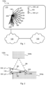
- Fig. 1 is a schematic diagram illustrating a communications network 100a where embodiments presented herein can be applied.
- the communications network 100 could be a third generation (3G) telecommunications network, a fourth generation (4G) telecommunications network, or a fifth (5G) telecommunications network and support any 3GPP telecommunications standard.
- the communications network 100a comprises a radio transceiver device 200 implemented as a network node and configured to, in a radio access network 110, provide network access to another radio transceiver device 300 implemented as a terminal device.
- the radio access network 110 is operatively connected to a core network 120.
- the core network 120 is in turn operatively connected to a service network 130, such as the Internet.
- the radio transceiver device 300 is thereby, via radio transceiver device 200, enabled to access services of, and exchange data with, the service network 130.
- network nodes are radio access network nodes, radio base stations, base transceiver stations, Node Bs, evolved Node Bs, g Node Bs, access points, and access nodes.
- Examples of terminal devices are wireless devices, mobile stations, mobile phones, handsets, wireless local loop phones, user equipment (UE), smartphones, laptop computers, tablet computers, network equipped sensors, network equipped vehicles, and so-called Internet of Things devices.
- the radio transceiver device 200 provides network access in the radio access network 110 by transmitting signals to, and receiving signals from, the radio transceiver device 300 in beams B1, B2, B3, B4, B5, B6, B7, B8.
- the signals could be transmitted from, and received by, a TRP 400 of the radio transceiver device 200.
- the TRP 400 could form an integral part of the radio transceiver device 200 or be physically separated from the radio transceiver device 200.
- radio transceiver device 300 moves in the direction given by arrow 150 from its current position p1 to a new position p2. It might then be needed to perform a beam sweep procedure in order to update which beam to be used for communication between radio transceiver device 200 and radio transceiver device 300
- Performing a beam sweep procedure in all beams B1-B8 might be costly in terms of signaling overhead and may delay the beam switch.
- the search space might be reduced by, in the beam sweep procedure, only considering neighboring beam (in angular sense) to the current beam. For example, assuming that radio transceiver device 300 at position p1 is communicating with radio transceiver device 200 in beam B3, a reduced set of candidate beams could include only beams B2, B3, B4 or only beams B1, B2, B3, B4, B5, which will reduce the signaling overhead.
- to only select beams close in angle to the used beam introduces a risk that the best candidate beam is missed. This is true since it is not always so that a neighboring beam (in angular sense) will be the best beam to switch over to.
- radio transceiver device 300 This might be the case e.g. when movement from position p1 to position p2 involves radio transceiver device 300 to pass from a position with line of sight to the radio transceiver device 200 to a position with no line of sight to the radio transceiver device 200.
- Fig. 2 schematically illustrates a communications network 100b representing a top view of a deployment scenario of the communications network 100a in Fig. 1 .
- movement from position p1 to position p2 causes radio transceiver device 300 to pass around a corner of a physical structure 500a, causing the line of sight to the radio transceiver device 200 to be broken.
- the strongest, and thus best candidate, beam might suddenly change to a beam transmitted in a significantly different angular direction and received by the radio transceiver device 300 at a strong reflection in another physical structure 500b, as exemplified by beam B6. If only beams, such as beams B1, B2, B4, B5, comparatively close in angle to the used beam B3 are tested, the best beam, as represented by beam B6, would be missed in this scenario.
- the embodiments disclosed herein enable the beam sweep procedure to take into account possible reflections from each beam, thus avoiding the best beam to be missed, e.g. in scenarios as disclosed above.
- the embodiments disclosed herein particularly relate to mechanisms for initiating a beam sweep procedure.
- a radio transceiver device 200 a method performed by the radio transceiver device 200, a computer program product comprising code, for example in the form of a computer program, that when run on a radio transceiver device 200, causes the radio transceiver device 200 to perform the method.
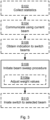
- Fig. 3 illustrating a method for initiating a beam sweep procedure as performed by the radio transceiver device 200 according to an embodiment.
- the radio transceiver device 200 is configured to perform step S108: S108: The radio transceiver device 200 initiates, for a candidate beam set, a beam sweep procedure for communication with another radio transceiver device 300. Each beam in the candidate beam set has an associated angular spread value. During the beam sweep procedure, beams in the candidate beam set are swept in an order weighted according to the angular spread values.
- Beams with high angular spread values might then be swept with higher priority than beams with low angular spread values. Further, beams with high angular spread values might then be selected with higher priority than beams with low angular spread values when determining which beams to include in the candidate beam set.
- one of the criteria is thus to capture the possibility of using beams that have reflective objects in their environment. Beams having reflective objects in their environment might cover areas far off in angle compared to the actual respective pointing directions of these beams. That is, in some aspects the angular spread value associated with a given beam in the candidate beam set represents an indication of reflectiveness of that given beam.
- the radio transceiver device 200 is configured to perform (optional) step S102: S102: The radio transceiver device 200 collects statistics of angular spread values per beam at least in the candidate beam set.
- the angular spread values per beam might then be aggregated, e.g. by calculating the average angular spread value per beam.
- Statistics of the angular spread values might be collected during comparatively long times, such as from several hours to several weeks or more. It could be that the radio transceiver device 200 collects statistics of angular spread values per beam only in the candidate beam set or in all possible beams.
- the radio transceiver device 200 has an ongoing communication with the radio transceiver device 300 when the beam sweep procedure is initiated.
- the radio transceiver device 200 is configured to perform (optional) step S104: S104: The radio transceiver device 200 communicates, using a current beam, with the radio transceiver device 300 before initiating the beam sweep procedure. The beam sweep procedure is then for continued communication with the radio transceiver device 300.
- the herein disclosed mechanisms can thus be used to reduce the risk of service interruption.
- the beam sweep procedure could thus be used for an initial connection where the radio transceiver device 300 only listens to signals transmitted in the beams during the beam sweep procedure.
- the radio transceiver device 300 is camping on a cell served by the radio transceiver device 200.
- beams in the candidate beam set are swept in an order weighted according to the angular spread values.
- the order is weighted so as to prioritize higher angular spread values over lower angular spread values. That is, this might cause beams with comparatively high angular spread values to be swept before beams with comparatively low angular spread values are swept.
- beams with comparatively high angular spread values are swept more often than beams with comparatively low angular spread values.
- less than all possible beams are included in the candidate beam set.
- the candidate beam set only includes beams with angular spread values larger than a threshold value.
- the threshold value could be set by the network, such as in a node of the radio access network 110 or in a node of the core network 120.
- the order in which the beams are swept, and/or how many times each beam is swept might depend on other factors, or parameters as well.
- the order in which the beams of the candidate beam set are swept might also depend on the angular direction, or pointing direction, of the beams so as to not miss beams that are close in angular direction to the currently used beam. That is, according to an embodiment the order further is weighted so as to prioritize smaller difference in angular direction to the current beam over larger angular difference to the current beam. Hence, this might enable a balance between prioritizing beams with high angular spread values and beams close in angular direction to the currently used beam.
- the angular spread value for a given beam in the candidate beam set is given by a channel property of a physical radio propagation channel as experienced in that given beam. That is, since each beam has a different angular pointing direction, the physical radio propagation channel might be unique for each beam and thus the physical radio propagation channel as experienced in a first given beam might be different from the physical radio propagation channel as experienced in a second given beam. There could be different ways to estimate, or measure the channel property. In some aspects the channel property is based on estimates and/or measures of sounding reference signals or on channel state information (CSI) reports.
- CSI channel state information
- the channel property is a rank value, a delay spread, and/or a singular value ratio (SVR) for the physical radio propagation channel.
- the rank generally depends on the angular spread at the transmitter (i.e., at the TRP 400) and at the receiver (i.e., at the radio transceiver device 300).
- Angular spread generally depends on the existence (or lack thereof) of multiple radio propagation paths between transmitter and receiver in different angular directions and might therefore be regarded as an indication of reflections in the coverage area of the beam.
- the rank increases with more reflections from surrounding objects, such as in the presence of physical structures 500a, 500b.
- the radio transceiver device 200 has an ongoing communication with the radio transceiver device 300 when the beam sweep procedure is initiated. A current beam is used for the ongoing communication. It could then be that the radio transceiver device 200 obtains an indication of a need to switch from the current beam to another beam in order to continue the communication with the radio transceiver device 300.
- the radio transceiver device 200 is configured to perform (optional) step S106: S106: The radio transceiver device 200 obtains an indication to switch from the current beam to another beam for continued communication with the radio transceiver device 300.
- Such indications are received signal strength from the radio transceiver device 300 being below a threshold value, reception of a report from the radio transceiver device 300 indicating that the received signal strength from the radio transceiver device 200 is below a threshold value, lack of an anticipated message (such as a response message or an acknowledgment message) from the radio transceiver device 300 within a predefined time limit, etc.
- the radio transceiver device 200 can initiate the beam sweep procedure.
- the current beam is generated by beamforming of an antenna arrangement of the radio transceiver device 200.
- the radio transceiver device 200 is configured to perform (optional) step S108a as part of initiating the beam sweep procedure in step S108: S108a: The radio transceiver device 200 adjusts weight values of the beamforming so as to sweep through the beams in the candidate beam set according to the order.
- the antenna arrangement is provided at at least one TRP 400 of the radio transceiver device 200. That is, one and the same radio transceiver device 200 could be configured to perform beam sweeping using at least one TRP 400.
- weight values of the beamforming are adjusted.
- the weight values are precoder weights being applied to a signal to be transmitted by the antenna arrangement.
- the beam sweep procedure comprises transmission of beam reference signals, such as channel state information reference signals (CSI-RS) in the candidate beam set.
- CSI-RS channel state information reference signals
- the radio transceiver device 300 the measures on the received reference signals and reports back a signal quality measure per beam (such as signal strength and/or rank value) to the radio transceiver device 200 for the radio transceiver device 200 to be able to determine which beam in the candidate beam set to use for communications with the radio transceiver device 300.
- CSI-RS channel state information reference signals
- the beam sweep procedure thus results in that a beam in the candidate beam set is selected for continued communication with the radio transceiver device 300.
- one of the candidate beams is selected for communication with the radio transceiver device 300.
- the radio transceiver device 200 is configured to perform (optional) step S110: S110: The radio transceiver device 200 initiates a switch to one of the beams in the candidate beam set for communication with the radio transceiver device 300.
- the selection criteria for which beam to switch to is based on at least one of signal strength and rank.
- the beam in the candidate beam set to which the switch is initiated is selected based on at least one of signal strength and rank value.
- the signal strength value is represented by a signal to noise ratio (SNR) value, a signal to interference plus noise ratio (SINR) value, a path loss value, or a channel quality indicator (CQI) value.
- SNR signal to noise ratio
- SINR signal to interference plus noise ratio
- CQI channel quality indicator
- rank value is represented by a channel rank value, a spatial multiplexing rank value, channel state information (CSI) report, a singular value ratio (SVR), a condition number, or a rank indicator (RI).
- CSI channel state information
- SVR singular value ratio
- RI rank indicator
- the signal strength value and the rank value are jointly obtained as a channel capacity measure.
- Fig. 4 schematically illustrates, in terms of a number of functional units, the components of a radio transceiver device 200 according to an embodiment.
- Processing circuitry 210 is provided using any combination of one or more of a suitable central processing unit (CPU), multiprocessor, microcontroller, digital signal processor (DSP), etc., capable of executing software instructions stored in a computer program product 610 (as in Fig. 6 ), e.g. in the form of a storage medium 230.
- the processing circuitry 210 may further be provided as at least one application specific integrated circuit (ASIC), or field programmable gate array (FPGA).
- ASIC application specific integrated circuit
- FPGA field programmable gate array
- the processing circuitry 210 is configured to cause the radio transceiver device 200 to perform a set of operations, or steps, S102-S110, as disclosed above.
- the storage medium 230 may store the set of operations
- the processing circuitry 210 may be configured to retrieve the set of operations from the storage medium 230 to cause the radio transceiver device 200 to perform the set of operations.
- the set of operations may be provided as a set of executable instructions.
- the processing circuitry 210 is thereby arranged to execute methods as herein disclosed.
- the storage medium 230 may also comprise persistent storage, which, for example, can be any single one or combination of magnetic memory, optical memory, solid state memory or even remotely mounted memory.
- the radio transceiver device 200 may further comprise a communications interface 220 at least configured for communications with other entities, nodes, functions and devices, such as the radio transceiver device 300, within the communications network 100.
- the communications interface 220 may comprise one or more transmitters and receivers, comprising analogue and digital components. Signals could be transmitted from, and received by, a TRP 400 of the radio transceiver device 200.
- the TRP 400 could form an integral part of the radio transceiver device 200 or be physically separated from the radio transceiver device 200.
- the communications interface 220 might thus optionally comprise the TRP 400.
- the processing circuitry 210 controls the general operation of the radio transceiver device 200 e.g. by sending data and control signals to the communications interface 220 and the storage medium 230, by receiving data and reports from the communications interface 220, and by retrieving data and instructions from the storage medium 230.
- Other components, as well as the related functionality, of the radio transceiver device 200 are omitted in order not to obscure the concepts presented herein.
- Fig. 5 schematically illustrates, in terms of a number of functional modules, the components of a radio transceiver device 200 according to an embodiment.
- the radio transceiver device 200 of Fig. 5 comprises an initiate module 210d configured to perform step S108.
- the radio transceiver device 200 of Fig. 5 may further comprise a number of optional functional modules, such as any of a collect module 210a configured to perform step S102, a communications module 210b configured to perform step S104, an obtain module 210c configured to perform step S106, an adjust module 210e configured to perform step S108a, and an initiate module 210f configured to perform step S110.
- each functional module 210a-210f may in one embodiment be implemented only in hardware and in another embodiment with the help of software, i.e., the latter embodiment having computer program instructions stored on the storage medium 230 which when run on the processing circuitry makes the radio transceiver device 200 perform the corresponding steps mentioned above in conjunction with Fig 5 .
- the modules correspond to parts of a computer program, they do not need to be separate modules therein, but the way in which they are implemented in software is dependent on the programming language used.
- one or more or all functional modules 210a-210f may be implemented by the processing circuitry 210, possibly in cooperation with the communications interface 220 and/or the storage medium 230.
- the processing circuitry 210 may thus be configured to from the storage medium 230 fetch instructions as provided by a functional module 210a-210f and to execute these instructions, thereby performing any steps as disclosed herein.
- the radio transceiver device 200 may be provided as a standalone device or as a part of at least one further device.
- the radio transceiver device 200 may be provided in a node of the radio access network 110 (as in the illustrative example of Fig. 1 ) or in a node of the core network 120.
- functionality of the radio transceiver device 200 may be distributed between at least two devices, or nodes. These at least two nodes, or devices, may either be part of the same network part (such as the radio access network or the core network) or may be spread between at least two such network parts.
- a first portion of the instructions performed by the radio transceiver device 200 may be executed in a first device, and a second portion of the of the instructions performed by the radio transceiver device 200 may be executed in a second device; the herein disclosed embodiments are not limited to any particular number of devices on which the instructions performed by the radio transceiver device 200 may be executed.
- the methods according to the herein disclosed embodiments are suitable to be performed by a radio transceiver device 200 residing in a cloud computational environment. Therefore, although a single processing circuitry 210 is illustrated in Fig. 4 the processing circuitry 210 may be distributed among a plurality of devices, or nodes. The same applies to the functional modules 210a-210f of Fig. 5 and the computer program 620 of Fig. 6 (see below).
- Fig. 6 shows one example of a computer program product 610 comprising computer readable storage medium 630.
- a computer program 620 can be stored, which computer program 620 can cause the processing circuitry 210 and thereto operatively coupled entities and devices, such as the communications interface 220 and the storage medium 230, to execute methods according to embodiments described herein.
- the computer program 620 and/or computer program product 610 may thus provide means for performing any steps as herein disclosed.
- the computer program product 610 is illustrated as an optical disc, such as a CD (compact disc) or a DVD (digital versatile disc) or a Blu-Ray disc.
- the computer program product 610 could also be embodied as a memory, such as a random access memory (RAM), a read-only memory (ROM), an erasable programmable read-only memory (EPROM), or an electrically erasable programmable read-only memory (EEPROM) and more particularly as a non-volatile storage medium of a device in an external memory such as a USB (Universal Serial Bus) memory or a Flash memory, such as a compact Flash memory.
- the computer program 620 is here schematically shown as a track on the depicted optical disk, the computer program 620 can be stored in any way which is suitable for the computer program product 610.
Landscapes
- Engineering & Computer Science (AREA)
- Computer Networks & Wireless Communication (AREA)
- Signal Processing (AREA)
- Mobile Radio Communication Systems (AREA)
Claims (15)
- Verfahren zum Initiieren eines Strahlablenkungsvorgangs, wobei das Verfahren durch eine Funksendeempfängervorrichtung (200) durchgeführt wird, wobei das Verfahren Folgendes umfasst:Initiieren (S108), für einen Kandidatenstrahlsatz, eines Strahlablenkungsvorgangs für die Kommunikation mit einer anderen Funksendeempfängervorrichtung (300),wobei jedem Strahl in dem Kandidatenstrahlsatz ein Winkelspreizungswert zugeordnet ist, wobei der Winkelspreizungswert für einen vorgegebenen Strahl in dem Kandidatenstrahlsatz aus einer Kanaleigenschaft des physikalischen Funkausbreitungskanals bestimmt wird, wie er in diesem vorgegebenen Strahl erfahren wird, undwobei während des Strahlablenkungsvorgangs Strahlen in dem Kandidatenstrahlsatz in einer Reihenfolge abgelenkt werden, die gemäß den Winkelspreizungswerten gewichtet ist.
- Verfahren nach Anspruch 1, ferner Folgendes umfassend:
Kommunizieren (S104), unter Verwendung eines aktuellen Strahls, mit der anderen Funksendeempfängervorrichtung (300) vor dem Initiieren des Strahlablenkungsvorgangs und wobei der Strahlablenkungsvorgang für die fortgesetzte Kommunikation mit der anderen Funksendeempfängervorrichtung (300) vorgesehen ist. - Verfahren nach Anspruch 1 oder 2, wobei die Reihenfolge so gewichtet ist, dass höhere Winkelspreizungswerte gegenüber niedrigeren Winkelspreizungswerten priorisiert werden.
- Verfahren nach einem der vorhergehenden Ansprüche, wobei der Winkelspreizungswert, der einem vorgegebenen Strahl in dem Kandidatenstrahlsatz zugeordnet ist, eine Angabe der Reflexionen darstellt, die der vorgegebene Strahl in seiner vorgegebenen Umgebung erfahren kann.
- Verfahren nach einem der vorhergehenden Ansprüche, wobei die Kanaleigenschaft auf Sounding-Referenz-Signalen oder auf einem Kanalzustandsinformationsbericht basiert.
- Verfahren nach einem der vorhergehenden Ansprüche, wobei die Kanaleigenschaft mindestens eines von Folgendem ist: einem Kanalrangwert, der dem für jeden Strahl verwendeten Rang entspricht, einer Verzögerungsspreizung und einem Singularwertverhältnis (singulär value ratio - SVR) für den physikalischen Funkausbreitungskanal.
- Verfahren nach einem der vorhergehenden Ansprüche, wobei der Kandidatenstrahlsatz nur Strahlen mit Winkelspreizungswerten beinhaltet, die größer als ein Schwellenwert sind.
- Verfahren nach einem der vorhergehenden Ansprüche, wobei die Reihenfolge ferner so gewichtet ist, dass eine kleinere Differenz der Winkelrichtung zu dem aktuellen Strahl gegenüber einer größeren Winkeldifferenz zu dem aktuellen Strahl priorisiert wird.
- Verfahren nach einem der vorhergehenden Ansprüche, wobei der Strahlablenkungsvorgang die Übertragung von Strahlreferenzsignalen, wie Kanalzustandsinformationsreferenzsignalen (channel state information reference signals - CSI-RS), umfasst.
- Verfahren nach einem der vorhergehenden Ansprüche, ferner Folgendes umfassend:
Sammeln (S102) von Statistiken von Winkelspreizungswerten pro Strahl mindestens in dem Kandidatenstrahlsatz zur Verwendung beim Schätzen des jeweiligen Winkelspreizungswerts. - Verfahren nach einem der vorhergehenden Ansprüche, ferner Folgendes umfassend:
Erhalten (S106) einer Angabe zum Umschalten von dem aktuellen Strahl zu einem anderen Strahl für die fortgesetzte Kommunikation mit der anderen Funksendeempfängervorrichtung (300) . - Funksendeempfängervorrichtung (200) zum Initiieren eines Strahlablenkungsvorgangs, wobei die Funksendeempfängervorrichtung (200) eine Verarbeitungsschaltung (210) umfasst, wobei die Verarbeitungsschaltung konfiguriert ist, um die Funksendeempfängervorrichtung (200) zu Folgendem zu veranlassen:Initiieren, für einen Kandidatenstrahlsatz, eines Strahlablenkungsvorgangs für die Kommunikation mit einer anderen Funksendeempfängervorrichtung (300), wobei jedem Strahl in dem Kandidatenstrahlsatz ein Winkelspreizungswert zugeordnet ist, wobei der Winkelspreizungswert für einen vorgegebenen Strahl in dem Kandidatenstrahlsatz aus einer Kanaleigenschaft eines physikalischen Funkausbreitungskanals bestimmt wird, wie er in diesem vorgegebenen Strahl erfahren wird; undwobei während des Strahlablenkungsvorgangs Strahlen in dem Kandidatenstrahlsatz in einer Reihenfolge abgelenkt werden, die gemäß den Winkelspreizungswerten gewichtet ist.
- Funksendeempfängervorrichtung (200) nach Anspruch 12, die ferner dazu konfiguriert ist, eines der Verfahren nach den Ansprüchen 2 bis 11 durchzuführen.
- Computerprogramm (620) zum Initiieren eines Strahlablenkungsvorgangs, wobei das Computerprogramm Computercode umfasst, der, wenn er auf einer Verarbeitungsschaltung (210) einer Funksendeempfängervorrichtung (200) ausgeführt wird, die Funksendeempfängervorrichtung (200) zu Folgendem veranlasst:Initiieren (S108), für einen Kandidatenstrahlsatz, eines Strahlablenkungsvorgangs für die Kommunikation mit einer anderen Funksendeempfängervorrichtung (300),wobei jedem Strahl in dem Kandidatenstrahlsatz ein Winkelspreizungswert zugeordnet ist, wobei der Winkelspreizungswert für einen vorgegebenen Strahl in dem Kandidatenstrahlsatz aus einer Kanaleigenschaft eines physikalischen Funkausbreitungskanals bestimmt wird, wie er in diesem vorgegebenen Strahl erfahren wird, undwobei während des Strahlablenkungsvorgangs Strahlen in dem Kandidatenstrahlsatz in einer Reihenfolge abgelenkt werden, die gemäß den Winkelspreizungswerten gewichtet ist.
- Computerprogrammprodukt (610), umfassend ein Computerprogramm (620) nach Anspruch 13 und ein computerlesbares Speichermedium (630), auf dem das Computerprogramm gespeichert ist.
Applications Claiming Priority (1)
| Application Number | Priority Date | Filing Date | Title |
|---|---|---|---|
| PCT/SE2017/050881 WO2019050440A1 (en) | 2017-09-06 | 2017-09-06 | INITIATION OF A BEAM SCANNING PROCEDURE |
Publications (3)
| Publication Number | Publication Date |
|---|---|
| EP3679656A1 EP3679656A1 (de) | 2020-07-15 |
| EP3679656B1 true EP3679656B1 (de) | 2024-12-11 |
| EP3679656C0 EP3679656C0 (de) | 2024-12-11 |
Family
ID=59914502
Family Applications (1)
| Application Number | Title | Priority Date | Filing Date |
|---|---|---|---|
| EP17769127.6A Active EP3679656B1 (de) | 2017-09-06 | 2017-09-06 | Initiierung eines strahlabtastungsvorgangs |
Country Status (3)
| Country | Link |
|---|---|
| US (1) | US11012138B2 (de) |
| EP (1) | EP3679656B1 (de) |
| WO (1) | WO2019050440A1 (de) |
Families Citing this family (8)
| Publication number | Priority date | Publication date | Assignee | Title |
|---|---|---|---|---|
| US11184125B2 (en) * | 2018-01-31 | 2021-11-23 | Qualcomm Incorporated | Network triggered reference signal coverage extension in wireless communication |
| US11206071B2 (en) | 2019-08-20 | 2021-12-21 | Qualcomm Incorporated | System and method for switching beamforming modes in millimeter wave systems |
| WO2021214512A1 (en) * | 2020-04-20 | 2021-10-28 | Telefonaktiebolaget Lm Ericsson (Publ) | Beam management for a radio transceiver device |
| US11515920B2 (en) * | 2020-08-07 | 2022-11-29 | Qualcomm Incorporated | Techniques for managing beams in multiple frequency bands |
| FI20206061A1 (en) | 2020-10-26 | 2022-04-27 | Nokia Technologies Oy | LINK BUDGET EVALUATION |
| US12294432B2 (en) | 2021-05-04 | 2025-05-06 | Telefonaktiebolaget Lm Ericsson (Publ) | Estimating angular spread of a wireless channel |
| CN113891468B (zh) * | 2021-10-09 | 2025-05-30 | 重庆两江卫星移动通信有限公司 | 一种卫星通信终端快速接入方法及系统 |
| CN119908075A (zh) * | 2022-09-30 | 2025-04-29 | Oppo广东移动通信有限公司 | 无线通信的方法、终端设备和网络设备 |
Citations (1)
| Publication number | Priority date | Publication date | Assignee | Title |
|---|---|---|---|---|
| US20080310380A1 (en) * | 2007-06-12 | 2008-12-18 | Sony Deutschland Gmbh | Adaptive history aware beam steering |
Family Cites Families (10)
| Publication number | Priority date | Publication date | Assignee | Title |
|---|---|---|---|---|
| US8508409B2 (en) * | 2008-11-04 | 2013-08-13 | Nec Corporation | Control method of wireless communication system, wireless communication system, adjustment method of array weight vector, and wireless communication device |
| KR101839386B1 (ko) | 2011-08-12 | 2018-03-16 | 삼성전자주식회사 | 무선 통신 시스템에서의 적응적 빔포밍 장치 및 방법 |
| US9876549B2 (en) * | 2014-05-23 | 2018-01-23 | Mediatek Inc. | Methods for efficient beam training and communications apparatus and network control device utilizing the same |
| US9786985B2 (en) * | 2014-08-27 | 2017-10-10 | Intel IP Corporation | Apparatus, system and method of beamforming training |
| CN106160807A (zh) * | 2015-04-09 | 2016-11-23 | 株式会社Ntt都科摩 | 波束选择方法、移动台和基站 |
| KR102205239B1 (ko) * | 2015-05-13 | 2021-01-20 | 텔레호낙티에볼라게트 엘엠 에릭슨(피유비엘) | 빔포밍 |
| US10069555B2 (en) * | 2016-04-13 | 2018-09-04 | Qualcomm Incorporated | System and method for beam management |
| WO2018174895A1 (en) * | 2017-03-24 | 2018-09-27 | Sony Mobile Communications Inc. | Systems, methods and devices for beam selection in a wireless communication system |
| US10404350B2 (en) * | 2017-06-05 | 2019-09-03 | Telefonaktiebolaget Lm Ericsson (Publ) | Beam management systems and methods |
| US10440727B2 (en) * | 2017-08-29 | 2019-10-08 | Telefonaktiebolaget Lm Ericsson (Publ) | Co-scheduling of terminal devices |
-
2017
- 2017-09-06 EP EP17769127.6A patent/EP3679656B1/de active Active
- 2017-09-06 US US16/638,569 patent/US11012138B2/en active Active
- 2017-09-06 WO PCT/SE2017/050881 patent/WO2019050440A1/en not_active Ceased
Patent Citations (1)
| Publication number | Priority date | Publication date | Assignee | Title |
|---|---|---|---|---|
| US20080310380A1 (en) * | 2007-06-12 | 2008-12-18 | Sony Deutschland Gmbh | Adaptive history aware beam steering |
Also Published As
| Publication number | Publication date |
|---|---|
| US20200220604A1 (en) | 2020-07-09 |
| WO2019050440A9 (en) | 2019-06-06 |
| WO2019050440A1 (en) | 2019-03-14 |
| US11012138B2 (en) | 2021-05-18 |
| EP3679656C0 (de) | 2024-12-11 |
| EP3679656A1 (de) | 2020-07-15 |
Similar Documents
| Publication | Publication Date | Title |
|---|---|---|
| EP3679656B1 (de) | Initiierung eines strahlabtastungsvorgangs | |
| EP3165022B1 (de) | Netzwerkknoten und verfahren zum treffen einer mobilitätsentscheidung unter berücksichtigung der strahlformungsfähigkeiten der benachbarten knoten | |
| EP3788724B1 (de) | Strahlverwaltung und teilnahme in einem strahlverwaltungsverfahren | |
| US10681674B2 (en) | Beam training for a radio transceiver device | |
| EP3639393B1 (de) | Strahlauswahl für kommunikationssignale | |
| EP3552319B1 (de) | Konfiguration von strahlformungseinstellungen für einen drahtlosen funksendeempfänger | |
| US10505607B2 (en) | Beam training for a wireless device | |
| US11089607B2 (en) | Co-scheduling of terminal devices | |
| EP3701637A1 (de) | Strahltraining eines funksendeempfängers | |
| EP3516783B1 (de) | Strahlfindungsverfahren | |
| EP3676964B1 (de) | Strahlenverwaltung in einer zelle | |
| CN112585883A (zh) | 来自网络节点的波束成形的信号传输 | |
| WO2023101578A1 (en) | Interference suppression in a wireless communication network | |
| EP3619817B1 (de) | Strahlformung basierend auf kombinierten strahlen | |
| US11522568B2 (en) | Identification of low performing radio branch |
Legal Events
| Date | Code | Title | Description |
|---|---|---|---|
| STAA | Information on the status of an ep patent application or granted ep patent |
Free format text: STATUS: UNKNOWN |
|
| STAA | Information on the status of an ep patent application or granted ep patent |
Free format text: STATUS: THE INTERNATIONAL PUBLICATION HAS BEEN MADE |
|
| PUAI | Public reference made under article 153(3) epc to a published international application that has entered the european phase |
Free format text: ORIGINAL CODE: 0009012 |
|
| STAA | Information on the status of an ep patent application or granted ep patent |
Free format text: STATUS: REQUEST FOR EXAMINATION WAS MADE |
|
| 17P | Request for examination filed |
Effective date: 20200319 |
|
| AK | Designated contracting states |
Kind code of ref document: A1 Designated state(s): AL AT BE BG CH CY CZ DE DK EE ES FI FR GB GR HR HU IE IS IT LI LT LU LV MC MK MT NL NO PL PT RO RS SE SI SK SM TR |
|
| AX | Request for extension of the european patent |
Extension state: BA ME |
|
| DAV | Request for validation of the european patent (deleted) | ||
| DAX | Request for extension of the european patent (deleted) | ||
| STAA | Information on the status of an ep patent application or granted ep patent |
Free format text: STATUS: EXAMINATION IS IN PROGRESS |
|
| 17Q | First examination report despatched |
Effective date: 20210322 |
|
| GRAP | Despatch of communication of intention to grant a patent |
Free format text: ORIGINAL CODE: EPIDOSNIGR1 |
|
| STAA | Information on the status of an ep patent application or granted ep patent |
Free format text: STATUS: GRANT OF PATENT IS INTENDED |
|
| INTG | Intention to grant announced |
Effective date: 20230727 |
|
| GRAJ | Information related to disapproval of communication of intention to grant by the applicant or resumption of examination proceedings by the epo deleted |
Free format text: ORIGINAL CODE: EPIDOSDIGR1 |
|
| STAA | Information on the status of an ep patent application or granted ep patent |
Free format text: STATUS: EXAMINATION IS IN PROGRESS |
|
| INTC | Intention to grant announced (deleted) | ||
| GRAP | Despatch of communication of intention to grant a patent |
Free format text: ORIGINAL CODE: EPIDOSNIGR1 |
|
| STAA | Information on the status of an ep patent application or granted ep patent |
Free format text: STATUS: GRANT OF PATENT IS INTENDED |
|
| INTG | Intention to grant announced |
Effective date: 20240701 |
|
| GRAS | Grant fee paid |
Free format text: ORIGINAL CODE: EPIDOSNIGR3 |
|
| GRAA | (expected) grant |
Free format text: ORIGINAL CODE: 0009210 |
|
| STAA | Information on the status of an ep patent application or granted ep patent |
Free format text: STATUS: THE PATENT HAS BEEN GRANTED |
|
| AK | Designated contracting states |
Kind code of ref document: B1 Designated state(s): AL AT BE BG CH CY CZ DE DK EE ES FI FR GB GR HR HU IE IS IT LI LT LU LV MC MK MT NL NO PL PT RO RS SE SI SK SM TR |
|
| REG | Reference to a national code |
Ref country code: GB Ref legal event code: FG4D |
|
| REG | Reference to a national code |
Ref country code: CH Ref legal event code: EP |
|
| REG | Reference to a national code |
Ref country code: IE Ref legal event code: FG4D |
|
| REG | Reference to a national code |
Ref country code: DE Ref legal event code: R096 Ref document number: 602017086707 Country of ref document: DE |
|
| U01 | Request for unitary effect filed |
Effective date: 20250106 |
|
| U07 | Unitary effect registered |
Designated state(s): AT BE BG DE DK EE FI FR IT LT LU LV MT NL PT RO SE SI Effective date: 20250115 |
|
| PG25 | Lapsed in a contracting state [announced via postgrant information from national office to epo] |
Ref country code: HR Free format text: LAPSE BECAUSE OF FAILURE TO SUBMIT A TRANSLATION OF THE DESCRIPTION OR TO PAY THE FEE WITHIN THE PRESCRIBED TIME-LIMIT Effective date: 20241211 |
|
| PG25 | Lapsed in a contracting state [announced via postgrant information from national office to epo] |
Ref country code: ES Free format text: LAPSE BECAUSE OF FAILURE TO SUBMIT A TRANSLATION OF THE DESCRIPTION OR TO PAY THE FEE WITHIN THE PRESCRIBED TIME-LIMIT Effective date: 20241211 |
|
| PG25 | Lapsed in a contracting state [announced via postgrant information from national office to epo] |
Ref country code: NO Free format text: LAPSE BECAUSE OF FAILURE TO SUBMIT A TRANSLATION OF THE DESCRIPTION OR TO PAY THE FEE WITHIN THE PRESCRIBED TIME-LIMIT Effective date: 20250311 |
|
| PG25 | Lapsed in a contracting state [announced via postgrant information from national office to epo] |
Ref country code: GR Free format text: LAPSE BECAUSE OF FAILURE TO SUBMIT A TRANSLATION OF THE DESCRIPTION OR TO PAY THE FEE WITHIN THE PRESCRIBED TIME-LIMIT Effective date: 20250312 |
|
| PG25 | Lapsed in a contracting state [announced via postgrant information from national office to epo] |
Ref country code: RS Free format text: LAPSE BECAUSE OF FAILURE TO SUBMIT A TRANSLATION OF THE DESCRIPTION OR TO PAY THE FEE WITHIN THE PRESCRIBED TIME-LIMIT Effective date: 20250311 |
|
| PG25 | Lapsed in a contracting state [announced via postgrant information from national office to epo] |
Ref country code: SM Free format text: LAPSE BECAUSE OF FAILURE TO SUBMIT A TRANSLATION OF THE DESCRIPTION OR TO PAY THE FEE WITHIN THE PRESCRIBED TIME-LIMIT Effective date: 20241211 |
|
| PG25 | Lapsed in a contracting state [announced via postgrant information from national office to epo] |
Ref country code: PL Free format text: LAPSE BECAUSE OF FAILURE TO SUBMIT A TRANSLATION OF THE DESCRIPTION OR TO PAY THE FEE WITHIN THE PRESCRIBED TIME-LIMIT Effective date: 20241211 |
|
| PG25 | Lapsed in a contracting state [announced via postgrant information from national office to epo] |
Ref country code: IS Free format text: LAPSE BECAUSE OF FAILURE TO SUBMIT A TRANSLATION OF THE DESCRIPTION OR TO PAY THE FEE WITHIN THE PRESCRIBED TIME-LIMIT Effective date: 20250411 |
|
| PG25 | Lapsed in a contracting state [announced via postgrant information from national office to epo] |
Ref country code: SK Free format text: LAPSE BECAUSE OF FAILURE TO SUBMIT A TRANSLATION OF THE DESCRIPTION OR TO PAY THE FEE WITHIN THE PRESCRIBED TIME-LIMIT Effective date: 20241211 |
|
| PG25 | Lapsed in a contracting state [announced via postgrant information from national office to epo] |
Ref country code: CZ Free format text: LAPSE BECAUSE OF FAILURE TO SUBMIT A TRANSLATION OF THE DESCRIPTION OR TO PAY THE FEE WITHIN THE PRESCRIBED TIME-LIMIT Effective date: 20241211 |
|
| PGFP | Annual fee paid to national office [announced via postgrant information from national office to epo] |
Ref country code: GB Payment date: 20250929 Year of fee payment: 9 |
|
| PLBE | No opposition filed within time limit |
Free format text: ORIGINAL CODE: 0009261 |
|
| STAA | Information on the status of an ep patent application or granted ep patent |
Free format text: STATUS: NO OPPOSITION FILED WITHIN TIME LIMIT |
|
| U20 | Renewal fee for the european patent with unitary effect paid |
Year of fee payment: 9 Effective date: 20250929 |
|
| 26N | No opposition filed |
Effective date: 20250912 |