EP3679590B1 - Fire rated radio frequency cable - Google Patents
Fire rated radio frequency cable Download PDFInfo
- Publication number
- EP3679590B1 EP3679590B1 EP18854197.3A EP18854197A EP3679590B1 EP 3679590 B1 EP3679590 B1 EP 3679590B1 EP 18854197 A EP18854197 A EP 18854197A EP 3679590 B1 EP3679590 B1 EP 3679590B1
- Authority
- EP
- European Patent Office
- Prior art keywords
- tape
- layer
- fire retardant
- outer conductor
- conductor
- Prior art date
- Legal status (The legal status is an assumption and is not a legal conclusion. Google has not performed a legal analysis and makes no representation as to the accuracy of the status listed.)
- Active
Links
Images



Classifications
-
- H—ELECTRICITY
- H01—ELECTRIC ELEMENTS
- H01B—CABLES; CONDUCTORS; INSULATORS; SELECTION OF MATERIALS FOR THEIR CONDUCTIVE, INSULATING OR DIELECTRIC PROPERTIES
- H01B11/00—Communication cables or conductors
- H01B11/18—Coaxial cables; Analogous cables having more than one inner conductor within a common outer conductor
- H01B11/1869—Construction of the layers on the outer side of the outer conductor
-
- H—ELECTRICITY
- H01—ELECTRIC ELEMENTS
- H01B—CABLES; CONDUCTORS; INSULATORS; SELECTION OF MATERIALS FOR THEIR CONDUCTIVE, INSULATING OR DIELECTRIC PROPERTIES
- H01B7/00—Insulated conductors or cables characterised by their form
- H01B7/17—Protection against damage caused by external factors, e.g. sheaths or armouring
- H01B7/29—Protection against damage caused by extremes of temperature or by flame
- H01B7/295—Protection against damage caused by extremes of temperature or by flame using material resistant to flame
-
- H—ELECTRICITY
- H01—ELECTRIC ELEMENTS
- H01B—CABLES; CONDUCTORS; INSULATORS; SELECTION OF MATERIALS FOR THEIR CONDUCTIVE, INSULATING OR DIELECTRIC PROPERTIES
- H01B11/00—Communication cables or conductors
- H01B11/18—Coaxial cables; Analogous cables having more than one inner conductor within a common outer conductor
- H01B11/1834—Construction of the insulation between the conductors
- H01B11/1856—Discontinuous insulation
- H01B11/1865—Discontinuous insulation having the shape of a bead
-
- H—ELECTRICITY
- H01—ELECTRIC ELEMENTS
- H01B—CABLES; CONDUCTORS; INSULATORS; SELECTION OF MATERIALS FOR THEIR CONDUCTIVE, INSULATING OR DIELECTRIC PROPERTIES
- H01B3/00—Insulators or insulating bodies characterised by the insulating materials; Selection of materials for their insulating or dielectric properties
- H01B3/02—Insulators or insulating bodies characterised by the insulating materials; Selection of materials for their insulating or dielectric properties mainly consisting of inorganic substances
- H01B3/08—Insulators or insulating bodies characterised by the insulating materials; Selection of materials for their insulating or dielectric properties mainly consisting of inorganic substances quartz; glass; glass wool; slag wool; vitreous enamels
-
- H—ELECTRICITY
- H01—ELECTRIC ELEMENTS
- H01B—CABLES; CONDUCTORS; INSULATORS; SELECTION OF MATERIALS FOR THEIR CONDUCTIVE, INSULATING OR DIELECTRIC PROPERTIES
- H01B11/00—Communication cables or conductors
- H01B11/18—Coaxial cables; Analogous cables having more than one inner conductor within a common outer conductor
-
- Y—GENERAL TAGGING OF NEW TECHNOLOGICAL DEVELOPMENTS; GENERAL TAGGING OF CROSS-SECTIONAL TECHNOLOGIES SPANNING OVER SEVERAL SECTIONS OF THE IPC; TECHNICAL SUBJECTS COVERED BY FORMER USPC CROSS-REFERENCE ART COLLECTIONS [XRACs] AND DIGESTS
- Y02—TECHNOLOGIES OR APPLICATIONS FOR MITIGATION OR ADAPTATION AGAINST CLIMATE CHANGE
- Y02A—TECHNOLOGIES FOR ADAPTATION TO CLIMATE CHANGE
- Y02A30/00—Adapting or protecting infrastructure or their operation
Definitions
- Coaxial cable is used to transmit electrical signals.
- a coaxial cable is made up of a center (or inner) conductor that is encapsulated by a helically wound dielectric insulating material (hereinafter referred to simply as "dielectric"), or any other suitable extruded forms of dielectric.
- the dielectric is overlaid with an outer conductor, which is annularly or helically corrugated.
- the dielectric is used to maintain a spacing (or gap) between the inner conductor and the outer conductor, where this spacing is necessary to obtain a prescribed characteristic impedance for the coaxial cable.
- the gap is often referred to as an "air gap", since it is desirable that air be the separator between the inner and outer conductors, notwithstanding the presence of the dielectric (which itself acts as a spacer).
- the entire assembly can be encased within an outer protective jacket.
- Such cables also known as radio frequency (RF) coaxial cables, are used for in-building communication and often for emergency communication systems. Given their use of emergency communications, such RF coaxial cables are now being required to pass International Building Code (IBC) / International Fire Code (IFC), Local Building Code / Local Fire Code, National Fire Protection Association (NFPA) 72, Chapter 24, NFPA 1221, and potentially NFPA 5000.
- IBC International Building Code
- IFC International Fire Code
- NFPA National Fire Protection Association
- the dielectric melts it fails in its purpose to keep the inner and outer conductors separated. Consequently, the inner conductor will short circuit with the outer conductor. When this happens, the coaxial cable is no longer usable for communication.
- Some other known dielectrics may withstand the temperature of a fire, and have sufficient strength to maintain the characteristic impedance, but are unsuitable because they significantly attenuate signals transmitted via the coaxial cable at normal temperatures.
- US 2 576 163 A discloses a concentric conductor electric cable with magnetic screen.
- EP 0 150 879 A2 discloses a flame resistant coaxial high frequency cable.
- US 2004/118591 A1 discloses a transmission line for radio frequency communications.
- such an outer protective barrier may be made up of a fire retardant tape such as one or more of the following: a) a woven glass substrate coated on both sides with a fire retardant compound, e.g., a mica tape, b) stainless steel, e.g., 304, 316, or steel tape, e.g., A606, c) copper tape, e.g., 110, which may be the same alloy used for the outer conductor, d) copper clad with stainless steel tape, or e) woven glass tape.
- a fire retardant tape such as one or more of the following: a) a woven glass substrate coated on both sides with a fire retardant compound, e.g., a mica tape, b) stainless steel, e.g., 304, 316, or steel tape, e.g., A606, c) copper tape, e.g., 110, which may be the same alloy used for the outer conductor, d) copper clad with stainless steel tape
- the metal tap layer and the fire retardant layer functions to seal the cable from air intrusion so as to prevent the oxidation and resulting degradation of outer/inner copper conductors, e.g., their conversion to cupric oxide, while also functioning to reinforce the structure of the cable during a fire and when the inventive cable is subjected to water jet spray, e.g., at the end of the Circuit Integrity UL 2196 test.
- a fire retardant thermoplastic jacket material may also be used to further enhance an inventive cable's ability to withstand high temperature and provide additional structural rigidity.
- a fire retardant tape may be incorporated to protect the jacket material from sharp edges of any incorporated metal tape and to help while the stainless steel tape, if employed.
- the inventive cable includes a dielectric that functions to separate the inner and outer conductors.
- a dielectric that functions to separate the inner and outer conductors.
- such a dielectric is not affected by fire and can maintain its performance during a fire and the temperatures related thereto.
- a coaxial cable may comprise an inner conductor, an outer conductor provided around the inner conductor, a dielectric provided comprising at least one layer of tape arranged around the outer conductor, wherein the tape layer is configured to prevent oxidation of the conductors.
- the tape layer may comprise at least three layers: (i) a proximal, with respect to the outer conductor, fire retardant tape layer, (ii) a distal, with respect to the outer conductor, fire retardant tape layer, and (iii) a metal tape layer between the proximal and distal fire retardant tape layers, for example.
- the tape layer may comprise a number of different fire retardant materials or material combinations, such as a steel, stainless steel, copper or copper clad with stainless steel, woven glass, woven glass substrate coated on both sides with a fire retardant compound.
- the dielectric may comprise, for example, an embedded ceramic, ceramic beads encapsulated with a fire retardant tape, (small) ceramic beads encapsulated in a flame retardant ceramic fiber mesh or ceramic beads inserted in a plastic dielectric tape.
- the small ceramic beads may comprise Al 2 O 3
- the mesh may comprise Al 2 O 3 and SiO 3 , for example.
- the inventive coaxial cable may comprise a fire retardant jacket configured annularly around the tape layer.
- a fire retardant jacket may comprise a fire retardant thermoplastic material, for example.
- the inventive cable may further comprise a tape layer (e.g., a metal layer of tape) and an additional tape layer configured annularly between the tape layer and the fire retardant jacket.
- the outer conductor of the inventive coaxial cable may be coated with an intumescent fire retardant paint, or a jacket formed over the outer conductor of an intumescent fire retardant compound.
- coaxial cables in accordance with embodiments of the disclosure are configured to survive and function in the face of the above-described tests and conditions.
- FIG. 1 shows an example of an outer conductor 1a, 1b, where the same type of conductor is shown before (1a) and after (1b) exposure to air and high temperature, e.g., fire conditions.
- the conductor shown in (1b) illustrates the effects of the formation of cupric oxide from copper due to such conditions.
- a new coaxial cable includes an outer structure or barrier that functions to seal the coaxial cable from air and protect an outer and inner conductor from oxidation during a fire.
- an outer protective barrier may include a fire retardant tape comprising one or more of the following: a) a woven glass substrate coated on both sides with a fire retardant compound, e.g., a mica tape, b) stainless steel, e.g., 304, 316, or steel tape, e.g., A606, c) copper tape, e.g., 110, which may be the same alloy used for the outer conductor, d) copper clad with stainless steel tape, or e) woven glass tape.
- a fire retardant tape comprising one or more of the following: a) a woven glass substrate coated on both sides with a fire retardant compound, e.g., a mica tape, b) stainless steel, e.g., 304, 316, or steel tape, e.g., A606,
- the metal tape layer and the fire retardant tape layer function to seal the cable from air intrusion so as to prevent the oxidation and resulting degradation of outer/inner copper conductors (i.e., prevent or minimize their conversion to cupric oxide), while also functioning to reinforce the structure of the cable during a fire, and/or when the inventive cable is subjected to a water jet spray, e.g., at the end of the UL 2196 test.
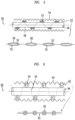
- FIGs. 2-3 and 5-7 show various configurations of inventive coaxial cables in accordance with the principles of the disclosure, while FIG. 4 illustrates an exemplary configuration of a suitable dielectric.
- FIG. 2 shows an illustrative, inventive cable 10 according to an embodiment of the disclosure.
- Inventive cable 10 is shown in a schematic view (a), an illustration (b), and a cut-away view (c) of the illustration of (b), the three views in combination illustrating inventive aspects of cable 10.
- an outer barrier may include two layers, denoted 12 and 14, of fire retardant tape (e.g., a mica-based tape) on either side of a stainless steel tape 16 (e.g., type 304, 316).
- Inner conductor 18 and outer conductor 20 are also shown, with a dielectric 22 disposed in the gap between inner conductor 18 and outer conductor 20.
- View (c) best illustrates the location of dielectric 22.
- Dielectric 22 may comprise ceramic beads 23 encapsulated within a fire retardant tape 25. Dielectric 22 functions to hold center conductor 18 in place with respect to outer conductor 20. It should be understood that other forms of ceramic beads, e.g., Al 2 O 3 , can be used.
- the barrier may further include a fire retardant jacket material 24 that is configured to surround fire retardant tape layer 12.
- stainless steel tape layer 16 may comprise a material that has a melting temperature of 1400-1455°C (2550-2651 °F), which is much higher than the melting temperature of a pure copper conductor (1083°C, 1981°F). Note that the UL 2196 test temperature is 1010°C (1850°F) and, thus, very close to the melting temperature of outer copper conductor 20.
- stainless steel tape 16 functions to shield outer conductor 20 from direct exposure to heat and air, and significantly reinforces the structural integrity of cable 10.
- Fire retardant tape 14 between outer copper conductor 20 and stainless steel tape 16 functions to seal outer conductor 20 from air at extreme temperatures to prevent the formation of cupric oxide.
- Fire retardant tape 12 functions to project jacket material 24 from sharp edges of stainless steel tape 16 and also shield stainless steel tape 16.
- fire retardant tapes 12 and 14 with fire retardant jacket 24 function to reinforce cable 10 and prevent copper conductors 18, 20 from oxidation and degradation.
- Cable 30 comprises two layers of fire retardant tape 32, 34 (e.g., a mica-based tape, ceramic tape (Al 2 O 3 and SiO 3 ), silica tape (SiO 3 ), or mesh braid (comprising Al 2 O 3 and SiO 3 ), and the like) between which is a steel tape 36 (e.g., A606 alloy).
- Cable 30 further comprises a fire retardant jacket material 38 (e.g., a flame retardant thermoplastic elastomer) that is configured to surround outer flame retardant tape 32. Similar to the arrangement of FIG.
- the combination of fire retardant tapes 32 and 34, steel tape 36, and fire retardant jacket 38 functions to protect copper conductors 40, 42 from degradation and oxidation.
- Center conductor 40 is held in place by a dielectric 44 that helically surrounds conductor 40 and may comprise a ceramic rope, for example. It should be understood, however, that other forms of a ceramic may be used.
- a substantially pure copper tape may be used in lieu of the steel or stainless steel tape.
- the copper tape may start to bond to itself when subjected to the extreme temperatures of a fire.
- Such self-bonding functions to create a tightly-sealed copper tube around outer conductor 42.
- Outer fire retardant tape 32 which is distal to inner conductor 40, functions to form a bond with the copper tape and slow the formation of cupric oxide.
- inner fire retardant tape 34 which is provided between copper tape 36 and outer conductor 42, functions to bond both copper layers, and create a tight seal to prevent oxidation of inner conductor 40 and outer conductor 42.
- fire retardant thermoplastic jacket 38 (e.g., elastomer) also functions to further enhance the inventive cable's ability to withstand high temperatures and provide additional structural rigidity.
- an additional fire retardant tape (not shown) may be included and function to protect jacket 38 from sharp edges of any metal tape and to help shield the tape.
- cable 30 may further comprise a thermal insulating layer 46 provided over outer conductor 42 that may be held in place by outer protective layers of tape 42, 44 to slow the rate of temperature increases to the inner core of cable 30.
- thermal insulating layer 46 may comprise an intumescent fire retardant paint, or a separate jacket of an intumescent fire retardant compound disposed over outer conductor 42.
- cable 30 may include a dielectric 44 that functions to separate inner conductor 40 from outer conductor 42, where the dielectric may comprise an embedded ceramic, for example.
- FIG. 4 shows an illustrative embodiment of a dielectric 100 that functions to separate an inner conductor from an outer conductor (the conductors not illustrated in FIG. 4 , but are clearly shown in FIGs. 2 and 3 ).
- Dielectric 100 may comprise a plurality of small ceramic beads 110a - 110n, where "n" indicates the last bead.
- each bead may comprise Al 2 O 3 .
- Dielectric 100 may further comprise a flame retardant ceramic fiber mesh 120 (e.g., made of Al 2 O 3 and SiO 3 ), for example, where mesh 120 may be braided.
- a flame retardant ceramic fiber mesh 120 e.g., made of Al 2 O 3 and SiO 3
- mesh 120 may be braided.
- Use of such a dielectric 100 to function as a separator helps to ensure that a required gap (e.g., air gap) between a center conductor and an outer conductor remains substantially constant, even in the presence of extreme temperatures inside the associated coaxial cable due to a fire.
- dielectric 52 may comprise small ceramic beads 53 in a fiber mesh 55, which may be further encapsulated in flame retardant tape 58.
- FIG. 6 shows another illustrative embodiment of a cable 60 that comprises a dielectric 62 that functions to separate an outer conductor 64 from an inner conductor 66.
- Dielectric 62 may comprise ceramic beads 63 that may be inserted in a plastic, fire retardant dielectric tape 65.
- Dielectric 62 may comprise Al 2 O 3 and SiO 3 (or only Al 2 O 3 , and may be configured as a rope or mesh.
- plastic dielectric tape 65 will melt, but beads 63, made of an aluminum oxide ceramic, for example, will not. Instead, beads 63 will function to maintain the necessary spacing between outer conductor 64 and inner conductor 66 and prevent a short circuit from being created between the two.
- dielectric 62 functions to hold inner conductor 66 and outer conductor 64 in place and allow for RF signals to pass through even at extreme temperatures, compared to existing cables.
- the air cable between the cable's center (inner) conductor and outer conductor should be maintained in order to achieve a certain characteristic impedance of the cable.
- the change in the voltage standing wave ratio of samples of the inventive cable that include a dielectric that comprises ceramic beads encapsulated within a fire retardant tape did not exceed a value of 1.23.
- the configuration of an RF cable determines the attenuation of an RF signal. Further, the attenuation due to a dielectric increases in proportion to the frequency of the RF signal being transmitted through the associated cable. In fact, the attenuation is independent of cable size and is determined only by the quantity and quality of the dielectric material.
- the inventors also conducted tests ond 7/8" or 1 ⁇ 2" coaxial cables that incorporated thick air dielectrics.
- the incorporation of stainless steel tape and flame retardant tapes provided protection for the cables (i.e., minimized degradation).
- FIG. 7 shows another illustrative embodiment of a coaxial cable 70 configured in accordance with the principles of the disclosure.
- cable 70 includes a tape 72 that includes both a layer of copper cladding 72a and a layer of stainless steel tape 72b.
- Tape 72 functions to reflect and resist heat generated by a fire, for example.
- Tape 72 may be configured annularly around an inner conductor 74 such that copper cladding 72a is proximal to (i.e., faces) inner conductor 74, while stainless steel tape 72b is proximal to (faces) an outer barrier (not shown).
- Cable 70 may also comprise a dielectric 78, described elsewhere herein.
- dielectric 78 may comprise 99.9% Quartzel silica (SiO 3 ) or 3M Nextel 440ceramic (Al 2 O 3 and SiO 3 ) ropes.
- a coaxial cable must be flexible enough to be able to route through tight spaces during installation within a building, for example. Accordingly, various embodiments disclosed herein may be configured to satisfy industry-specified bend specifications and can be produced in large quantities.
Landscapes
- Chemical & Material Sciences (AREA)
- Inorganic Chemistry (AREA)
- Insulated Conductors (AREA)
- Communication Cables (AREA)
Applications Claiming Priority (2)
| Application Number | Priority Date | Filing Date | Title |
|---|---|---|---|
| US201762556296P | 2017-09-08 | 2017-09-08 | |
| PCT/CN2018/104657 WO2019047929A1 (en) | 2017-09-08 | 2018-09-07 | FIRE RESISTANT RADIO FREQUENCY CABLE |
Publications (3)
| Publication Number | Publication Date |
|---|---|
| EP3679590A1 EP3679590A1 (en) | 2020-07-15 |
| EP3679590A4 EP3679590A4 (en) | 2021-05-12 |
| EP3679590B1 true EP3679590B1 (en) | 2023-08-09 |
Family
ID=65633478
Family Applications (1)
| Application Number | Title | Priority Date | Filing Date |
|---|---|---|---|
| EP18854197.3A Active EP3679590B1 (en) | 2017-09-08 | 2018-09-07 | Fire rated radio frequency cable |
Country Status (7)
| Country | Link |
|---|---|
| US (1) | US11152138B2 (enExample) |
| EP (1) | EP3679590B1 (enExample) |
| JP (2) | JP7237940B2 (enExample) |
| KR (1) | KR102497173B1 (enExample) |
| CN (1) | CN111095442B (enExample) |
| AU (1) | AU2018328574B2 (enExample) |
| WO (1) | WO2019047929A1 (enExample) |
Families Citing this family (11)
| Publication number | Priority date | Publication date | Assignee | Title |
|---|---|---|---|---|
| EP3679590B1 (en) * | 2017-09-08 | 2023-08-09 | Nokia Shanghai Bell Co., Ltd. | Fire rated radio frequency cable |
| WO2019236336A1 (en) * | 2018-06-06 | 2019-12-12 | Trilogy Communications, Inc. | Electrical cable and methods of making the same |
| US12283400B2 (en) * | 2019-07-18 | 2025-04-22 | Rfs Technologies, Inc. | Dielectric structure, a method of manufacturing thereof and a fire rated radio frequency cable having the dielectric structure |
| US10726974B1 (en) | 2019-12-13 | 2020-07-28 | American Fire Wire, Inc. | Fire resistant coaxial cable for distributed antenna systems |
| US11328837B2 (en) | 2020-01-24 | 2022-05-10 | Nokia Shanghai Bell Co., Ltd. | Fire rated multiconductor cable |
| US11942233B2 (en) * | 2020-02-10 | 2024-03-26 | American Fire Wire, Inc. | Fire resistant corrugated coaxial cable |
| WO2021215044A1 (ja) * | 2020-04-21 | 2021-10-28 | 東京特殊電線株式会社 | 同軸フラットケーブル |
| CN112071494B (zh) * | 2020-08-21 | 2021-11-23 | 齐齐哈尔沈江线缆制造有限公司 | 一种自闭合式半开放阻燃电缆 |
| US11746603B2 (en) * | 2022-03-06 | 2023-09-05 | Joe Fox | Drill string tool comprising coaxial dielectric segments |
| JP2025509658A (ja) * | 2022-03-16 | 2025-04-11 | カーライル・インターコネクト・テクノロジーズ・インコーポレイテッド | 編組SiO2コアを有する同軸ケーブル |
| US12469621B1 (en) | 2024-09-24 | 2025-11-11 | American Fire Wire, Inc. | Fire resistant radiating coaxial cable |
Family Cites Families (30)
| Publication number | Priority date | Publication date | Assignee | Title |
|---|---|---|---|---|
| BE472664A (enExample) * | 1945-05-10 | |||
| JPS5363685U (enExample) | 1976-10-25 | 1978-05-29 | ||
| FR2534735B1 (fr) | 1982-10-15 | 1985-07-05 | Habia Sa | Revetement isolant |
| US4549041A (en) * | 1983-11-07 | 1985-10-22 | Fujikura Ltd. | Flame-retardant cross-linked composition and flame-retardant cable using same |
| DE3402762A1 (de) | 1984-01-27 | 1985-08-01 | Philips Patentverwaltung Gmbh, 2000 Hamburg | Flammwidriges koaxiales hochfrequenzkabel |
| US4800351A (en) * | 1987-09-10 | 1989-01-24 | Andrew Corporation | Radiating coaxial cable with improved flame retardancy |
| JPH01109607A (ja) | 1987-10-22 | 1989-04-26 | Showa Electric Wire & Cable Co Ltd | 難燃性らせん漏洩同軸ケーブル |
| EP0503129A1 (de) | 1991-03-09 | 1992-09-16 | kabelmetal electro GmbH | Koaxiales elektrisches Hochfrequenzkabel |
| US5422614A (en) * | 1993-02-26 | 1995-06-06 | Andrew Corporation | Radiating coaxial cable for plenum applications |
| JPH0727021U (ja) | 1993-10-21 | 1995-05-19 | 矢崎総業株式会社 | 耐火ケーブル |
| DE19737759A1 (de) | 1997-08-29 | 1999-03-04 | Alsthom Cge Alcatel | Koaxiales Hochfrequenz-Kabel |
| US20020117325A1 (en) * | 2001-02-23 | 2002-08-29 | Mennone Michael P. | Flame resistant cable structure |
| US20030122636A1 (en) | 2001-12-28 | 2003-07-03 | Dibenedetto Arturo | Radio frequency coaxial cable and method for making same |
| US20040118591A1 (en) | 2002-12-20 | 2004-06-24 | Radio Frequency Systems, Inc. | Transmission line for radio frequency communications |
| US20050183878A1 (en) * | 2004-02-23 | 2005-08-25 | Herbort Tom A. | Plenum cable |
| JP3738774B2 (ja) | 2004-04-15 | 2006-01-25 | 住友電気工業株式会社 | シールド電線 |
| CN200986608Y (zh) | 2006-12-19 | 2007-12-05 | 昆山火凤凰线缆有限公司 | 矿物绝缘金属护套四合一耐火光电缆 |
| KR20090104367A (ko) * | 2008-03-31 | 2009-10-06 | 이광주 | 자동차용 점화 니크롬선 케이블 |
| CN201522890U (zh) * | 2009-10-20 | 2010-07-07 | 常州八益电缆有限公司 | 核电站用低烟无卤阻燃型同轴电缆 |
| CN202633485U (zh) | 2012-06-18 | 2012-12-26 | 江苏帝诚线缆有限公司 | 一种射频同轴电缆 |
| US20140037956A1 (en) * | 2012-08-01 | 2014-02-06 | Umesh Kumar Sopory | High voltage high temperature heater cables, connectors, and insulations |
| CN203931596U (zh) * | 2014-06-04 | 2014-11-05 | 安徽华宇电缆集团有限公司 | 一种船用及海洋工程用同轴射频电缆 |
| US9757599B2 (en) * | 2014-09-10 | 2017-09-12 | Dymat Construction Products, Inc. | Systems and methods for fireproofing cables and other structural members |
| CN104616823A (zh) * | 2015-01-31 | 2015-05-13 | 丁年生 | 一种耐高温同轴电缆 |
| US10373738B2 (en) * | 2015-05-08 | 2019-08-06 | Radix Wire & Cable, Llc | Insulated wire construction with liner |
| CN204787819U (zh) | 2015-07-09 | 2015-11-18 | 广东金贝尔通信科技有限公司 | 射频同轴电缆烧结炉隔热保温结构 |
| CN205122263U (zh) * | 2015-10-08 | 2016-03-30 | 杭州创远电缆有限公司 | 一种防火视频电缆 |
| CN106373650B (zh) * | 2016-11-08 | 2018-07-03 | 四川明星电缆股份有限公司 | 一种第三代核电站用同轴电缆及制造工艺 |
| CN206471151U (zh) | 2017-01-23 | 2017-09-05 | 浙江吉祥电缆制造有限公司 | 一种多芯耐火同轴电缆 |
| EP3679590B1 (en) * | 2017-09-08 | 2023-08-09 | Nokia Shanghai Bell Co., Ltd. | Fire rated radio frequency cable |
-
2018
- 2018-09-07 EP EP18854197.3A patent/EP3679590B1/en active Active
- 2018-09-07 AU AU2018328574A patent/AU2018328574B2/en active Active
- 2018-09-07 CN CN201880058189.6A patent/CN111095442B/zh active Active
- 2018-09-07 JP JP2020513749A patent/JP7237940B2/ja active Active
- 2018-09-07 WO PCT/CN2018/104657 patent/WO2019047929A1/en not_active Ceased
- 2018-09-07 KR KR1020207009711A patent/KR102497173B1/ko active Active
- 2018-09-07 US US16/644,232 patent/US11152138B2/en active Active
-
2022
- 2022-01-17 JP JP2022004933A patent/JP2022043350A/ja active Pending
Also Published As
| Publication number | Publication date |
|---|---|
| KR20200051704A (ko) | 2020-05-13 |
| JP2020533740A (ja) | 2020-11-19 |
| CN111095442A (zh) | 2020-05-01 |
| KR102497173B1 (ko) | 2023-02-07 |
| JP7237940B2 (ja) | 2023-03-13 |
| AU2018328574B2 (en) | 2022-08-18 |
| CA3074522A1 (en) | 2019-03-14 |
| US11152138B2 (en) | 2021-10-19 |
| US20200211739A1 (en) | 2020-07-02 |
| WO2019047929A1 (en) | 2019-03-14 |
| AU2018328574A1 (en) | 2020-03-19 |
| EP3679590A4 (en) | 2021-05-12 |
| CN111095442B (zh) | 2024-05-24 |
| JP2022043350A (ja) | 2022-03-15 |
| EP3679590A1 (en) | 2020-07-15 |
Similar Documents
| Publication | Publication Date | Title |
|---|---|---|
| US11152138B2 (en) | Fire rated radio frequency cable | |
| CN113178279B (zh) | 耐火多导体电缆 | |
| US9773585B1 (en) | Fire resistant coaxial cable | |
| US20190237221A1 (en) | Method of Testing a Fire Resistant Coaxial Cable | |
| JP2020533740A5 (enExample) | ||
| WO2008142385A1 (en) | Fire-resistant cable | |
| US20240221978A1 (en) | Method of Installing Fire Resistant Corrugated Coaxial Cable | |
| US20250232891A1 (en) | Dielectric structure, a method of manufacturing thereof and a fire rated radio frequency cable having the dielectric structure | |
| CA3074522C (en) | Fire rated radio frequency cable | |
| WO2019236336A1 (en) | Electrical cable and methods of making the same | |
| CN212461187U (zh) | 一种防火耐高温型电缆 | |
| KR102152767B1 (ko) | 복합 전선 | |
| EP2413331A1 (en) | Flexible middle voltage (3.6/6 kV - 6/10 kV - 8.7/15 kV - 12/20 kV) electric cable resistant against fire, mechanical impacts and water jets, according to the Standard BS 7846:2009 CAT. F60 | |
| CN219143854U (zh) | 一种环保型中压阻燃耐火电缆 | |
| EP3886121B1 (en) | Fire-resistant cable | |
| CN211654409U (zh) | 一种具有高防火性的布电线 | |
| CN223728490U (zh) | 一种矿物防火电缆 | |
| KR20240136586A (ko) | 내화 동축 케이블 | |
| CN223941571U (zh) | 一种中压防火电缆 | |
| CN104835562B (zh) | 一种矿物质绝缘防火电缆 | |
| CN113674898A (zh) | 航空用耐腐蚀、耐老化、耐低温及高温的阻燃尼龙电线 | |
| KR20250174470A (ko) | 내화 동축 케이블 | |
| KR20250174442A (ko) | 내화 동축 케이블 | |
| TW202217864A (zh) | 防燃性電纜 | |
| CN107240453A (zh) | 一种耐高温阻燃电缆 |
Legal Events
| Date | Code | Title | Description |
|---|---|---|---|
| STAA | Information on the status of an ep patent application or granted ep patent |
Free format text: STATUS: THE INTERNATIONAL PUBLICATION HAS BEEN MADE |
|
| PUAI | Public reference made under article 153(3) epc to a published international application that has entered the european phase |
Free format text: ORIGINAL CODE: 0009012 |
|
| STAA | Information on the status of an ep patent application or granted ep patent |
Free format text: STATUS: REQUEST FOR EXAMINATION WAS MADE |
|
| 17P | Request for examination filed |
Effective date: 20200325 |
|
| AK | Designated contracting states |
Kind code of ref document: A1 Designated state(s): AL AT BE BG CH CY CZ DE DK EE ES FI FR GB GR HR HU IE IS IT LI LT LU LV MC MK MT NL NO PL PT RO RS SE SI SK SM TR |
|
| AX | Request for extension of the european patent |
Extension state: BA ME |
|
| DAV | Request for validation of the european patent (deleted) | ||
| DAX | Request for extension of the european patent (deleted) | ||
| A4 | Supplementary search report drawn up and despatched |
Effective date: 20210412 |
|
| RIC1 | Information provided on ipc code assigned before grant |
Ipc: H01B 7/295 20060101AFI20210406BHEP Ipc: H01B 11/18 20060101ALI20210406BHEP |
|
| STAA | Information on the status of an ep patent application or granted ep patent |
Free format text: STATUS: EXAMINATION IS IN PROGRESS |
|
| 17Q | First examination report despatched |
Effective date: 20220127 |
|
| GRAP | Despatch of communication of intention to grant a patent |
Free format text: ORIGINAL CODE: EPIDOSNIGR1 |
|
| STAA | Information on the status of an ep patent application or granted ep patent |
Free format text: STATUS: GRANT OF PATENT IS INTENDED |
|
| INTG | Intention to grant announced |
Effective date: 20230309 |
|
| GRAS | Grant fee paid |
Free format text: ORIGINAL CODE: EPIDOSNIGR3 |
|
| GRAA | (expected) grant |
Free format text: ORIGINAL CODE: 0009210 |
|
| STAA | Information on the status of an ep patent application or granted ep patent |
Free format text: STATUS: THE PATENT HAS BEEN GRANTED |
|
| AK | Designated contracting states |
Kind code of ref document: B1 Designated state(s): AL AT BE BG CH CY CZ DE DK EE ES FI FR GB GR HR HU IE IS IT LI LT LU LV MC MK MT NL NO PL PT RO RS SE SI SK SM TR |
|
| REG | Reference to a national code |
Ref country code: GB Ref legal event code: FG4D |
|
| REG | Reference to a national code |
Ref country code: CH Ref legal event code: EP |
|
| REG | Reference to a national code |
Ref country code: DE Ref legal event code: R096 Ref document number: 602018055184 Country of ref document: DE |
|
| REG | Reference to a national code |
Ref country code: IE Ref legal event code: FG4D |
|
| REG | Reference to a national code |
Ref country code: LT Ref legal event code: MG9D |
|
| REG | Reference to a national code |
Ref country code: NL Ref legal event code: MP Effective date: 20230809 |
|
| REG | Reference to a national code |
Ref country code: AT Ref legal event code: MK05 Ref document number: 1598489 Country of ref document: AT Kind code of ref document: T Effective date: 20230809 |
|
| PG25 | Lapsed in a contracting state [announced via postgrant information from national office to epo] |
Ref country code: GR Free format text: LAPSE BECAUSE OF FAILURE TO SUBMIT A TRANSLATION OF THE DESCRIPTION OR TO PAY THE FEE WITHIN THE PRESCRIBED TIME-LIMIT Effective date: 20231110 |
|
| PG25 | Lapsed in a contracting state [announced via postgrant information from national office to epo] |
Ref country code: IS Free format text: LAPSE BECAUSE OF FAILURE TO SUBMIT A TRANSLATION OF THE DESCRIPTION OR TO PAY THE FEE WITHIN THE PRESCRIBED TIME-LIMIT Effective date: 20231209 |
|
| PG25 | Lapsed in a contracting state [announced via postgrant information from national office to epo] |
Ref country code: SE Free format text: LAPSE BECAUSE OF FAILURE TO SUBMIT A TRANSLATION OF THE DESCRIPTION OR TO PAY THE FEE WITHIN THE PRESCRIBED TIME-LIMIT Effective date: 20230809 Ref country code: RS Free format text: LAPSE BECAUSE OF FAILURE TO SUBMIT A TRANSLATION OF THE DESCRIPTION OR TO PAY THE FEE WITHIN THE PRESCRIBED TIME-LIMIT Effective date: 20230809 Ref country code: PT Free format text: LAPSE BECAUSE OF FAILURE TO SUBMIT A TRANSLATION OF THE DESCRIPTION OR TO PAY THE FEE WITHIN THE PRESCRIBED TIME-LIMIT Effective date: 20231211 Ref country code: NO Free format text: LAPSE BECAUSE OF FAILURE TO SUBMIT A TRANSLATION OF THE DESCRIPTION OR TO PAY THE FEE WITHIN THE PRESCRIBED TIME-LIMIT Effective date: 20231109 Ref country code: NL Free format text: LAPSE BECAUSE OF FAILURE TO SUBMIT A TRANSLATION OF THE DESCRIPTION OR TO PAY THE FEE WITHIN THE PRESCRIBED TIME-LIMIT Effective date: 20230809 Ref country code: LV Free format text: LAPSE BECAUSE OF FAILURE TO SUBMIT A TRANSLATION OF THE DESCRIPTION OR TO PAY THE FEE WITHIN THE PRESCRIBED TIME-LIMIT Effective date: 20230809 Ref country code: LT Free format text: LAPSE BECAUSE OF FAILURE TO SUBMIT A TRANSLATION OF THE DESCRIPTION OR TO PAY THE FEE WITHIN THE PRESCRIBED TIME-LIMIT Effective date: 20230809 Ref country code: IS Free format text: LAPSE BECAUSE OF FAILURE TO SUBMIT A TRANSLATION OF THE DESCRIPTION OR TO PAY THE FEE WITHIN THE PRESCRIBED TIME-LIMIT Effective date: 20231209 Ref country code: HR Free format text: LAPSE BECAUSE OF FAILURE TO SUBMIT A TRANSLATION OF THE DESCRIPTION OR TO PAY THE FEE WITHIN THE PRESCRIBED TIME-LIMIT Effective date: 20230809 Ref country code: GR Free format text: LAPSE BECAUSE OF FAILURE TO SUBMIT A TRANSLATION OF THE DESCRIPTION OR TO PAY THE FEE WITHIN THE PRESCRIBED TIME-LIMIT Effective date: 20231110 Ref country code: FI Free format text: LAPSE BECAUSE OF FAILURE TO SUBMIT A TRANSLATION OF THE DESCRIPTION OR TO PAY THE FEE WITHIN THE PRESCRIBED TIME-LIMIT Effective date: 20230809 Ref country code: AT Free format text: LAPSE BECAUSE OF FAILURE TO SUBMIT A TRANSLATION OF THE DESCRIPTION OR TO PAY THE FEE WITHIN THE PRESCRIBED TIME-LIMIT Effective date: 20230809 |
|
| PG25 | Lapsed in a contracting state [announced via postgrant information from national office to epo] |
Ref country code: PL Free format text: LAPSE BECAUSE OF FAILURE TO SUBMIT A TRANSLATION OF THE DESCRIPTION OR TO PAY THE FEE WITHIN THE PRESCRIBED TIME-LIMIT Effective date: 20230809 |
|
| PG25 | Lapsed in a contracting state [announced via postgrant information from national office to epo] |
Ref country code: ES Free format text: LAPSE BECAUSE OF FAILURE TO SUBMIT A TRANSLATION OF THE DESCRIPTION OR TO PAY THE FEE WITHIN THE PRESCRIBED TIME-LIMIT Effective date: 20230809 |
|
| PG25 | Lapsed in a contracting state [announced via postgrant information from national office to epo] |
Ref country code: SM Free format text: LAPSE BECAUSE OF FAILURE TO SUBMIT A TRANSLATION OF THE DESCRIPTION OR TO PAY THE FEE WITHIN THE PRESCRIBED TIME-LIMIT Effective date: 20230809 Ref country code: RO Free format text: LAPSE BECAUSE OF FAILURE TO SUBMIT A TRANSLATION OF THE DESCRIPTION OR TO PAY THE FEE WITHIN THE PRESCRIBED TIME-LIMIT Effective date: 20230809 Ref country code: ES Free format text: LAPSE BECAUSE OF FAILURE TO SUBMIT A TRANSLATION OF THE DESCRIPTION OR TO PAY THE FEE WITHIN THE PRESCRIBED TIME-LIMIT Effective date: 20230809 Ref country code: EE Free format text: LAPSE BECAUSE OF FAILURE TO SUBMIT A TRANSLATION OF THE DESCRIPTION OR TO PAY THE FEE WITHIN THE PRESCRIBED TIME-LIMIT Effective date: 20230809 Ref country code: DK Free format text: LAPSE BECAUSE OF FAILURE TO SUBMIT A TRANSLATION OF THE DESCRIPTION OR TO PAY THE FEE WITHIN THE PRESCRIBED TIME-LIMIT Effective date: 20230809 Ref country code: CZ Free format text: LAPSE BECAUSE OF FAILURE TO SUBMIT A TRANSLATION OF THE DESCRIPTION OR TO PAY THE FEE WITHIN THE PRESCRIBED TIME-LIMIT Effective date: 20230809 Ref country code: SK Free format text: LAPSE BECAUSE OF FAILURE TO SUBMIT A TRANSLATION OF THE DESCRIPTION OR TO PAY THE FEE WITHIN THE PRESCRIBED TIME-LIMIT Effective date: 20230809 |
|
| REG | Reference to a national code |
Ref country code: CH Ref legal event code: PL |
|
| REG | Reference to a national code |
Ref country code: DE Ref legal event code: R097 Ref document number: 602018055184 Country of ref document: DE |
|
| PG25 | Lapsed in a contracting state [announced via postgrant information from national office to epo] |
Ref country code: LU Free format text: LAPSE BECAUSE OF NON-PAYMENT OF DUE FEES Effective date: 20230907 |
|
| REG | Reference to a national code |
Ref country code: BE Ref legal event code: MM Effective date: 20230930 |
|
| PG25 | Lapsed in a contracting state [announced via postgrant information from national office to epo] |
Ref country code: LU Free format text: LAPSE BECAUSE OF NON-PAYMENT OF DUE FEES Effective date: 20230907 Ref country code: IT Free format text: LAPSE BECAUSE OF FAILURE TO SUBMIT A TRANSLATION OF THE DESCRIPTION OR TO PAY THE FEE WITHIN THE PRESCRIBED TIME-LIMIT Effective date: 20230809 Ref country code: MC Free format text: LAPSE BECAUSE OF FAILURE TO SUBMIT A TRANSLATION OF THE DESCRIPTION OR TO PAY THE FEE WITHIN THE PRESCRIBED TIME-LIMIT Effective date: 20230809 |
|
| PLBE | No opposition filed within time limit |
Free format text: ORIGINAL CODE: 0009261 |
|
| STAA | Information on the status of an ep patent application or granted ep patent |
Free format text: STATUS: NO OPPOSITION FILED WITHIN TIME LIMIT |
|
| REG | Reference to a national code |
Ref country code: IE Ref legal event code: MM4A |
|
| PG25 | Lapsed in a contracting state [announced via postgrant information from national office to epo] |
Ref country code: IE Free format text: LAPSE BECAUSE OF NON-PAYMENT OF DUE FEES Effective date: 20230907 |
|
| 26N | No opposition filed |
Effective date: 20240513 |
|
| PG25 | Lapsed in a contracting state [announced via postgrant information from national office to epo] |
Ref country code: CH Free format text: LAPSE BECAUSE OF NON-PAYMENT OF DUE FEES Effective date: 20230930 |
|
| PG25 | Lapsed in a contracting state [announced via postgrant information from national office to epo] |
Ref country code: IE Free format text: LAPSE BECAUSE OF NON-PAYMENT OF DUE FEES Effective date: 20230907 Ref country code: CH Free format text: LAPSE BECAUSE OF NON-PAYMENT OF DUE FEES Effective date: 20230930 Ref country code: SI Free format text: LAPSE BECAUSE OF FAILURE TO SUBMIT A TRANSLATION OF THE DESCRIPTION OR TO PAY THE FEE WITHIN THE PRESCRIBED TIME-LIMIT Effective date: 20230809 |
|
| PG25 | Lapsed in a contracting state [announced via postgrant information from national office to epo] |
Ref country code: BE Free format text: LAPSE BECAUSE OF NON-PAYMENT OF DUE FEES Effective date: 20230930 |
|
| PG25 | Lapsed in a contracting state [announced via postgrant information from national office to epo] |
Ref country code: BG Free format text: LAPSE BECAUSE OF FAILURE TO SUBMIT A TRANSLATION OF THE DESCRIPTION OR TO PAY THE FEE WITHIN THE PRESCRIBED TIME-LIMIT Effective date: 20230809 |
|
| PG25 | Lapsed in a contracting state [announced via postgrant information from national office to epo] |
Ref country code: BG Free format text: LAPSE BECAUSE OF FAILURE TO SUBMIT A TRANSLATION OF THE DESCRIPTION OR TO PAY THE FEE WITHIN THE PRESCRIBED TIME-LIMIT Effective date: 20230809 |
|
| PG25 | Lapsed in a contracting state [announced via postgrant information from national office to epo] |
Ref country code: CY Free format text: LAPSE BECAUSE OF FAILURE TO SUBMIT A TRANSLATION OF THE DESCRIPTION OR TO PAY THE FEE WITHIN THE PRESCRIBED TIME-LIMIT; INVALID AB INITIO Effective date: 20180907 |
|
| PG25 | Lapsed in a contracting state [announced via postgrant information from national office to epo] |
Ref country code: HU Free format text: LAPSE BECAUSE OF FAILURE TO SUBMIT A TRANSLATION OF THE DESCRIPTION OR TO PAY THE FEE WITHIN THE PRESCRIBED TIME-LIMIT; INVALID AB INITIO Effective date: 20180907 |
|
| PGFP | Annual fee paid to national office [announced via postgrant information from national office to epo] |
Ref country code: DE Payment date: 20250730 Year of fee payment: 8 |
|
| PGFP | Annual fee paid to national office [announced via postgrant information from national office to epo] |
Ref country code: GB Payment date: 20250731 Year of fee payment: 8 |
|
| PGFP | Annual fee paid to national office [announced via postgrant information from national office to epo] |
Ref country code: FR Payment date: 20250808 Year of fee payment: 8 |
|
| PG25 | Lapsed in a contracting state [announced via postgrant information from national office to epo] |
Ref country code: TR Free format text: LAPSE BECAUSE OF FAILURE TO SUBMIT A TRANSLATION OF THE DESCRIPTION OR TO PAY THE FEE WITHIN THE PRESCRIBED TIME-LIMIT Effective date: 20230809 |
|
| REG | Reference to a national code |
Ref country code: DE Ref legal event code: R081 Ref document number: 602018055184 Country of ref document: DE Owner name: NOKIA SOLUTIONS (SHANGHAI) CO., LTD., CN Free format text: FORMER OWNER: NOKIA SHANGHAI BELL CO., LTD., SHANGHAI, CN |