EP3679369B1 - Bestimmung von eigenschaften eines kohlenwasserstofffluids - Google Patents
Bestimmung von eigenschaften eines kohlenwasserstofffluids Download PDFInfo
- Publication number
- EP3679369B1 EP3679369B1 EP17784995.7A EP17784995A EP3679369B1 EP 3679369 B1 EP3679369 B1 EP 3679369B1 EP 17784995 A EP17784995 A EP 17784995A EP 3679369 B1 EP3679369 B1 EP 3679369B1
- Authority
- EP
- European Patent Office
- Prior art keywords
- chamber
- volume
- hydrocarbon fluid
- pressure
- fluid
- Prior art date
- Legal status (The legal status is an assumption and is not a legal conclusion. Google has not performed a legal analysis and makes no representation as to the accuracy of the status listed.)
- Active
Links
Images


Classifications
-
- G—PHYSICS
- G01—MEASURING; TESTING
- G01N—INVESTIGATING OR ANALYSING MATERIALS BY DETERMINING THEIR CHEMICAL OR PHYSICAL PROPERTIES
- G01N33/00—Investigating or analysing materials by specific methods not covered by groups G01N1/00 - G01N31/00
- G01N33/26—Oils; Viscous liquids; Paints; Inks
- G01N33/28—Oils, i.e. hydrocarbon liquids
- G01N33/2823—Raw oil, drilling fluid or polyphasic mixtures
-
- E—FIXED CONSTRUCTIONS
- E21—EARTH OR ROCK DRILLING; MINING
- E21B—EARTH OR ROCK DRILLING; OBTAINING OIL, GAS, WATER, SOLUBLE OR MELTABLE MATERIALS OR A SLURRY OF MINERALS FROM WELLS
- E21B49/00—Testing the nature of borehole walls; Formation testing; Methods or apparatus for obtaining samples of soil or well fluids, specially adapted to earth drilling or wells
- E21B49/08—Obtaining fluid samples or testing fluids, in boreholes or wells
- E21B49/087—Well testing, e.g. testing for reservoir productivity or formation parameters
- E21B49/0875—Well testing, e.g. testing for reservoir productivity or formation parameters determining specific fluid parameters
-
- G—PHYSICS
- G01—MEASURING; TESTING
- G01N—INVESTIGATING OR ANALYSING MATERIALS BY DETERMINING THEIR CHEMICAL OR PHYSICAL PROPERTIES
- G01N1/00—Sampling; Preparing specimens for investigation
- G01N1/02—Devices for withdrawing samples
- G01N1/10—Devices for withdrawing samples in the liquid or fluent state
- G01N1/18—Devices for withdrawing samples in the liquid or fluent state with provision for splitting samples into portions
-
- G—PHYSICS
- G01—MEASURING; TESTING
- G01N—INVESTIGATING OR ANALYSING MATERIALS BY DETERMINING THEIR CHEMICAL OR PHYSICAL PROPERTIES
- G01N25/00—Investigating or analyzing materials by the use of thermal means
- G01N25/16—Investigating or analyzing materials by the use of thermal means by investigating thermal coefficient of expansion
-
- G—PHYSICS
- G01—MEASURING; TESTING
- G01N—INVESTIGATING OR ANALYSING MATERIALS BY DETERMINING THEIR CHEMICAL OR PHYSICAL PROPERTIES
- G01N33/00—Investigating or analysing materials by specific methods not covered by groups G01N1/00 - G01N31/00
- G01N33/24—Earth materials
- G01N33/241—Earth materials for hydrocarbon content
-
- G—PHYSICS
- G01—MEASURING; TESTING
- G01N—INVESTIGATING OR ANALYSING MATERIALS BY DETERMINING THEIR CHEMICAL OR PHYSICAL PROPERTIES
- G01N33/00—Investigating or analysing materials by specific methods not covered by groups G01N1/00 - G01N31/00
- G01N33/26—Oils; Viscous liquids; Paints; Inks
- G01N33/28—Oils, i.e. hydrocarbon liquids
- G01N33/2835—Specific substances contained in the oils or fuels
- G01N33/2841—Gas in oils, e.g. hydrogen in insulating oils
-
- G—PHYSICS
- G01—MEASURING; TESTING
- G01N—INVESTIGATING OR ANALYSING MATERIALS BY DETERMINING THEIR CHEMICAL OR PHYSICAL PROPERTIES
- G01N7/00—Analysing materials by measuring the pressure or volume of a gas or vapour
-
- G—PHYSICS
- G01—MEASURING; TESTING
- G01N—INVESTIGATING OR ANALYSING MATERIALS BY DETERMINING THEIR CHEMICAL OR PHYSICAL PROPERTIES
- G01N1/00—Sampling; Preparing specimens for investigation
- G01N1/02—Devices for withdrawing samples
- G01N1/10—Devices for withdrawing samples in the liquid or fluent state
- G01N2001/1062—Sampling under constant temperature, pressure, or the like
-
- G—PHYSICS
- G01—MEASURING; TESTING
- G01N—INVESTIGATING OR ANALYSING MATERIALS BY DETERMINING THEIR CHEMICAL OR PHYSICAL PROPERTIES
- G01N9/00—Investigating density or specific gravity of materials; Analysing materials by determining density or specific gravity
- G01N9/26—Investigating density or specific gravity of materials; Analysing materials by determining density or specific gravity by measuring pressure differences
Definitions
- the present invention relates to a method for determining at least one property of a hydrocarbon fluid, such as e.g. compressibility, vapor pressure, gas/oil volume ratio, etc. as well an apparatus suitable for implementing this method.
- a hydrocarbon fluid such as e.g. compressibility, vapor pressure, gas/oil volume ratio, etc.
- Hydrocarbon fluids contained in or recovered from subterranean formations are complex fluids containing many different chemical compounds.
- PVT pressure-volume-temperature
- the equipment due to the large volume of the chamber, the equipment has a large dead volume, which may result in poor accuracy.
- step (c) comprises measuring a pressure both in the first chamber and in the second chamber.
- the absolute pressure in the first chamber at step (a) is from 100 to 1000 bar, preferably from 200 to 800 bar, more preferably from 350 to 600 bar.
- the temperature in the first chamber is equal to the temperature in the second chamber during all of steps (b) and (c).
- the ratio of the fixed volume of the first chamber to the fixed volume of the second chamber is from 0.2 to 5, preferably from 0.5 to 2, and more preferably is from 0.8 to 1.25.
- the property of the hydrocarbon fluid is selected from a compressibility, a gas / oil volume ratio, a vapor pressure and a thermal expansion coefficient.
- the method comprises a step of calculating at least one value of the property of the hydrocarbon fluid, said calculation being based on:
- the transfer system comprises a rotative valve which comprises a rotative body having one or more cavities, said cavities being configured for alternatively being:
- the ratio of the volume of the first chamber to the volume of the second chamber is from 0.2 to 5, preferably from 0.5 to 2, and more preferably is from 0.8 to 1.25.
- the apparatus comprises at least one temperature sensor, preferably in the first chamber and/or in the second chamber.
- the apparatus further comprises:
- the analysis data pertain to a property of the hydrocarbon fluid selected from a compressibility, a gas / oil volume ratio, a vapor pressure and a thermal expansion coefficient.
- the apparatus comprises a control module which is configured to send instructions for actuating the transfer system.
- the invention also relates to a computer-readable storage medium on which this computer program is stored.
- the present invention addresses the need expressed in the prior art.
- the invention provides an improved method of measuring properties of a complex hydrocarbon fluid, which is easier to implement and relies on equipment having a smaller size.
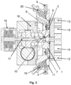
- the apparatus of the invention comprises a first chamber 1, a second chamber 2, a transfer system 3 and a feeding system 4.
- the apparatus of the invention can be designed so as to accommodate elevated pressure within the first chamber 1, the second chamber 2 and the transfer system 3.
- the apparatus is thus preferably constructed so that it can accommodate an absolute pressure of at least 50 bar, more preferably of at least 100 bar, even more preferably of at least 200 bar, and most preferably of at least 500 bar, in at least the first chamber 1 and the transfer system 3, and desirably also in the second chamber 2.
- a main block 11 which can be made of stainless steel or any other pressure-resistant material, wherein channels are e.g. carved and/or drilled so as to form the first chamber 1, the second chamber 2, as well as conduits leading to and from each of the first chamber 1 and the second chamber 2.
- the channels forming the first chamber 1 and second chamber 2 in the main block 11 may have open surfaces which are closed by one or, as illustrated, by two respective side blocks 12, 13 which are firmly fixed to and pressed against the main block 11 over the respective chambers 1, 2.
- respective windows 14, 15 may be provided in these side blocks 12, 13 so that the contents of the chambers 1, 2 may be monitored from the outside, owing to a monitoring system.
- these windows 14, 15 may be made of sapphire, or any other transparent or translucid material able to withstand high pressure.
- the monitoring system may comprise respective cameras so as to e.g. optically analyze the contents of the chambers 1, 2.
- Both of the first chamber 1 and second chamber 2 are provided with respective pressure sensors 7, 8.
- the main block may be provided with cutouts communicating with the chambers 1, 2, opposite the side blocks 12, 13.
- the pressure sensors 7, 8 may be inserted into these cutouts.
- one open surface area of each chamber 1, 2 may be closed by a respective pressure sensor 7, 8, opposite the respective side block 12, 13.
- the part of each pressure sensor 7, 8 in contact with the inside of the respective chamber 1, 2 can be in particular a deformable membrane the position of which depends on the pressure within the respective chamber 1, 2.
- the feeding system 4 may comprise a conduit leading to the first chamber 1, as well as a connector for connecting the feeding system 4 to a source of fluid, such as a source of hydrocarbon fluid.
- the conduit can be e.g. drilled within the main block 11, and it can be in fluid communication with the connector.
- a venting system 6 is provided for transferring fluid contained in the second chamber 2 to a third chamber, not shown on the drawings.
- the venting system 6 may comprise a conduit leading to the second chamber 2 as well as a connector for connecting the venting system 6 to directly to the third chamber, or to an external conduit in fluid communication with the third chamber.
- the conduit of the venting system leading to the second chamber 2 can be e . g . drilled within the main block 11, and it can be in fluid communication with the connector.
- this third chamber is preferably of a significantly larger volume than the first chamber 1 and the second chamber 2.
- the third chamber could also be provided within the main block 11 similarly to the first chamber 1 and the second chamber 2.
- fluid ingress and egress to and from the first chamber 1 can be performed via two respective conduits, one which is part of the feeding system 4 and the other one (hereafter referred to as "the first conduit 23 ") which leads to the transfer system 3.
- a closing mechanism can be provided to close the feeding system 4 and thereby isolate the first chamber 1 from the external source of fluid.
- said closing mechanism is a needle valve 19.
- fluid ingress and egress to and from the second chamber 2 can be performed via two respective conduits, one which is part of the venting system 6 and the other one (hereafter referred to as "the second conduit 23 ") which leads to the transfer system 3.
- a closing mechanism can be provided to close the venting system 6 and thereby isolate the second chamber 2 from the third chamber.
- said closing mechanism is a needle valve 20.
- a purge system 5 is provided for purging at least one of the first chamber 1 and second chamber 2.
- the purge system comprises a third conduit 25 connected to the transfer system 3, which can be e . g . drilled within the main block 11, as well as a connector for connecting the purge system 5 to a purging device configured to provide a vacuum within the first chamber 1 and/or the second chamber 2.
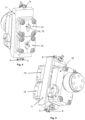
- the rotative body 9 can be firmly pressed against the main block 11 (the cavities 21, 22 being on the surface in contact with the main block 11).
- the rotative body 9 is preferably made of an elastomeric material such as polyimide (for instance of the brand Vespel ® ).
- polyimide for instance of the brand Vespel ®
- the rotative body 9 can rotate against the main block 11 in a leak-tight manner.
- rotation of the rotative body 9 can be effected owing to a shaft 17 driven by an engine 16.
- a speed reducing mechanism 18 is advantageously connected to the shaft 17, so as to provide a fine control of the angular position of the rotative body 9.
- the reducing factor can be for instance from 10 to 10,000, preferably from 100 to 5,000, more preferably from 500 to 2,000.
- a reducing factor of 1,000, for instance, means that 1,000 rotations of the engine-driven shaft 17 correspond to only one full rotation of the rotative body 9.
- the reducing mechanism 18 can for instance drive an intermediate part 10 which bears against the rotative body 9, so as to firmly compress said rotative body 9 against the main block 11.
- the intermediate part 10 may for instance be made of ceramics or stainless steel. It may be disk-shaped.
- the first chamber 1 and the second chamber 2 are of a fixed, i.e. constant volume.
- these chambers 1, 2 are not provided with a piston or any other volume variation device.
- the presence of a pressure sensor in each chamber may result in infinitesimal variations in volume, as the pressure sensor typically comprises a deformable membrane.
- infinitesimal variations in volume have no significant impact on the method described below and can thus be neglected.
- the volume of the first chamber 1 and of the second chamber 2 may be different.
- the ratio of the volume of the first chamber 1 to the volume of the second chamber 2 may thus range from 0.2 to 5, preferably from 0.5 to 2, and more preferably is from 0.8 to 1.25. More preferably, the volume of the first chamber 1 is substantially identical to the volume of the second chamber 2 (ratio of 1).
- first chamber 1 or the second chamber 2 may have a relatively flat shape defined in a main plane.
- the first chamber 1 or the second chamber 2 may have a main axis from an inlet to an outlet of the chamber.
- cross-section of the first chamber 1 or the second chamber 2 (and preferably both) which is orthogonal to the main axis may progressively increase and then progressively decrease from the inlet to the outlet, so that the first chamber 1 or the second chamber 2 (and preferably both) may assume a general diamond or lozenge shape in the main plane. This can be in particular useful to accurately monitor the position of a gas-liquid interface in the respective chamber if necessary.
- each cavity 21, 22 in the rotative body 9 may range from e.g. 0.005 ⁇ L to 10 ⁇ L, preferably from 0.01 ⁇ L to 2 ⁇ L, more preferably from 0.02 to 1 ⁇ L.
- the volume of the third chamber when present, may range from e.g. 1 mL to 10 L, preferably from 10 mL to 1 L, and more preferably from 50 mL to 200 mL.
- the apparatus is preferably provided with one or more temperature sensors (such as thermocouples) and is also preferably provided with a temperature regulation system, which may comprise a heating and/or cooling system. For instance, use may be made of a refrigerant circuit and/or resistive heating.
- more than one set of first chamber 1, second chamber 2, transfer system 3 and associated conduits, connectors and piping may be provided in the apparatus. This can be useful if several measurements are to be performed in parallel so as to achieve a more accurate determination of the properties of the fluid based on a statistical analysis.
- the apparatus of the invention may also comprise - or be associated in a larger system with - an analysis module and/or a control module.
- the analysis module may receive data from the various pressure and/or temperature sensors, from the monitoring system, from the user and/or from the control module and provide analysis data as an output.
- the maximum dimension of the apparatus may be less than 1 m, preferably less than 60 cm, more preferably less than 40 cm.
- the volume occupied by the apparatus may be less than 100 L, preferably less than 50 L, more preferably less than 30 L, and most preferably less than 15 L.
- the apparatus may be portable. It may also be placed in an extraction well if desired.
- the hydrocarbon fluid used in the method of the invention is preferably a hydrocarbon fluid recovered from a subterranean formation. It is preferably a complex fluid comprising various hydrocarbon compounds and optionally water as well as contaminants or chemicals used in the process of hydrocarbon recovery (surfactants, carbon dioxide, etc.).
- the purge system 5 may be connected to the first chamber 1 and/or the second chamber 2, for example via the transfer system 3 as illustrated, and a vacuum may be applied so as to substantially empty the first chamber 1 and/or the second chamber 2.
- the first chamber 1 and/or the second chamber 2 may thus be depressurized down to an absolute pressure of less than 0.1 bar, or less than 0.01 bar, or less than 0.002 bar or less than 0.001 bar.
- the first chamber 1 is fluidically isolated from the second chamber 2 by a proper setting of the transfer system 3.
- the second chamber 2 is also fluidically isolated from the third chamber (not shown) by closing the venting system 6 (e.g. owing to the needle valve 20).
- the first chamber 1 is filled with hydrocarbon fluid owing to the feeding system 4.
- the hydrocarbon fluid is introduced into the first chamber 1 under elevated pressure, i.e. preferably at an absolute pressure of at least 50 bar, or at least 100 bar, or at least 200 bar, or at least 300 bar, or at least 400 bar, or at least 500 bar.
- elevated pressure i.e. preferably at an absolute pressure of at least 50 bar, or at least 100 bar, or at least 200 bar, or at least 300 bar, or at least 400 bar, or at least 500 bar.
- possible absolute pressure ranges at this step are from 100 to 1000 bar, preferably from 200 to 800 bar, more preferably from 350 to 600 bar.
- the hydrocarbon fluid in the first chamber 1 is preferably in a liquid and/or supercritical state. It preferably does not comprise any gaseous fraction.
- the pressure of the hydrocarbon fluid in the first chamber 1 at the introduction stage can be achieved directly owing to the pressure of the source of hydrocarbon fluid, notably if the apparatus is placed within an extraction well so as to collect hydrocarbon fluid from the subterranean formation in situ.
- a pump may be used to pressurize the hydrocarbon fluid directed to the apparatus.
- the method of the invention comprises a succession of respective steps of:
- step (b) are repeated a plurality of times, for instance from 5 to 1,000 times, preferably from 10 to 500 times, more preferably from 20 to 200 times, wherein at least some of the successive samples of step (b) have different volumes.
- the pressure in the second chamber 2 is initially low, as the second chamber 2 is initially substantially empty.
- the pressure in the second chamber 2 at this stage can be 1 bar or less than 1 bar if the second chamber 2 has been purged as described above.
- the pressure of the first chamber 1 is initially high, as described above. Successive samples of hydrocarbon fluid are thus transferred from the first chamber 1 to the second chamber 2 owing to this difference in pressure, by properly actuating the transfer system 3. Therefore, the pressure in the first chamber 1 tends to decrease over time while the pressure in the second chamber 2 tends to increase over time.
- stage C can be performed simultaneously with stage D and/or E, if a different cavity 21 is used at stage C than at stage D and/or E.
- the pressure in the second chamber 2 is lower than the pressure in the first chamber 1, such that:
- the hydrocarbon fluid in the first chamber 1 comprises at least two phases, including a gaseous phase and a liquid phase.
- either samples of the liquid phase or samples of the gaseous phase in the first chamber 1 may be transferred to the second chamber 2.
- conduit connecting the first chamber 1 to the transfer system 3 may be connected at the top of the first chamber 1 (the first chamber 1 being below the second chamber 2, and the transfer system 3 being between the two chambers 1, 2). In this case, samples of the gaseous phase are transferred from the first chamber 1 to the second chamber 2.
- Switching from one configuration to the other may be easily performed simply by turning the apparatus upside down.
- the transfers of samples may be stopped once the pressure in the first chamber 1 is equal to the pressure in the second chamber 2, or they can be stopped before reaching that point.
- all samples may have the same unitary volume, or samples of different volumes may be used. Using samples having a larger volume may be advantageous if the measured pressure tends to vary little at each step, whereas using samples having a smaller volume may be advantageous if the measured pressure tends to vary a lot at each step.
- the vapor pressure of the hydrocarbon fluid at a given temperature may be determined as follows.
- the pressure in the first chamber 1 is plotted as a function of the cumulative volume of fluid transferred from the first chamber 1 to the second chamber 2.
- the vapor pressure is reached when the first bubble of gas appears in the first chamber 1. This corresponds to a sudden change in the slope of the plotted pressure.
Landscapes
- Life Sciences & Earth Sciences (AREA)
- Chemical & Material Sciences (AREA)
- Health & Medical Sciences (AREA)
- Physics & Mathematics (AREA)
- Engineering & Computer Science (AREA)
- General Health & Medical Sciences (AREA)
- Immunology (AREA)
- Pathology (AREA)
- General Physics & Mathematics (AREA)
- Biochemistry (AREA)
- Analytical Chemistry (AREA)
- Geology (AREA)
- Medicinal Chemistry (AREA)
- Food Science & Technology (AREA)
- Chemical Kinetics & Catalysis (AREA)
- Oil, Petroleum & Natural Gas (AREA)
- General Chemical & Material Sciences (AREA)
- Mining & Mineral Resources (AREA)
- General Life Sciences & Earth Sciences (AREA)
- Environmental & Geological Engineering (AREA)
- Hydrology & Water Resources (AREA)
- Fluid Mechanics (AREA)
- Geochemistry & Mineralogy (AREA)
- Remote Sensing (AREA)
- Sampling And Sample Adjustment (AREA)
Claims (15)
- Verfahren zum Bestimmen mindestens einer Eigenschaft eines Kohlenwasserstofffluids, umfassend:(a) Bereitstellen einer ersten Kammer (1), die mit dem Kohlenwasserstofffluid gefüllt ist, und einer zweiten Kammer (2), die im Wesentlichen leer ist, wobei jede von der ersten Kammer (1) und der zweiten Kammer (2) ein festes Volumen aufweisen;(b) Übertragen einer Probe von Kohlenwasserstofffluid von der ersten Kammer (1) in die zweite Kammer (2);(c) Messen eines Drucks in mindestens einer von der ersten Kammer (1) und der zweiten Kammer (2);
dadurch gekennzeichnet, dass das Verfahren ferner Folgendes umfasst(d) mehrmaliges Wiederholen von Schritt (b) und (c), wobei zumindest einige der aufeinanderfolgenden Proben von Schritt (b) unterschiedliche Volumen aufweisen. - Verfahren nach Anspruch 1, wobei Schritt (c) ein Messen eines Drucks sowohl in der ersten Kammer (1) als auch in der zweiten Kammer (2) umfasst.
- Verfahren nach einem der Ansprüche 1 bis 2, wobei das Volumen der bei jedem Schritt (b) übertragenen Probe von 0,005 µl bis 10 µl, vorzugsweise von 0,01 µl bis 2 µl, bevorzugter von 0,02 bis 1 µl ist und/oder wobei der absolute Druck in der ersten Kammer (1) bei Schritt (a) von 100 bis 1000 bar, vorzugsweise von 200 bis 800 bar, bevorzugter von 350 bis 600 bar ist.
- Verfahren nach einem der Ansprüche 1 bis 3, wobei:- die Temperatur in der ersten Kammer (1) und in der zweiten Kammer (2) während aller Schritte (b) und (c) auf demselben vorbestimmten Wert ist; und/oder- die Temperatur in der ersten Kammer (1) während aller Schritte (b) und (c) gleich wie die Temperatur in der zweiten Kammer (2) ist; oder- das Verfahren einen oder mehrere Schritte (c) umfasst, wobei die Temperatur in der ersten Kammer (1) und/oder der zweiten Kammer (2) einen ersten Wert aufweist, gefolgt von einem oder mehreren Schritten (c), wobei die Temperatur in der ersten Kammer (1) und/oder der zweiten Kammer (2) einen zweiten Wert aufweist, der sich von dem ersten Wert unterscheidet.
- Verfahren nach einem der Ansprüche 1 bis 4, wobei:- das Volumen der ersten Kammer (1) von 5 µl bis 2 ml, vorzugsweise von 10 µl bis 1 ml, bevorzugter von 50 µl bis 200 µl ist; und/oder- das Volumen der zweiten Kammer (2) von 5 µl bis 2 ml, vorzugsweise von 10 µl bis 1 ml, bevorzugter 50 µl bis 200 µl ist; undwobei vorzugsweise das Verhältnis des festen Volumens der ersten Kammer (1) zu dem festen Volumen der zweiten Kammer (2) von 0,2 bis 5, vorzugsweise von 0,5 bis 2 und bevorzugter von 0,8 bis 1,25 ist.
- Verfahren nach einem der Ansprüche 1 bis 5, das außerdem mindestens einen folgenden Schritt umfasst:
(e) Übertragen eines Teils der Kohlenwasserstoffflüssigkeit, die in der ersten Kammer (1) oder in der zweiten Kammer (2) enthalten ist, in eine dritte Kammer und Messen eines Drucks in der dritten Kammer; und
wobei das Volumen der dritten Kammer vorzugsweise mindestens 10-mal, vorzugsweise mindestens 20-mal, bevorzugter mindestens 100-mal größer ist als das Volumen der ersten Kammer (1) und als das Volumen der zweiten Kammer (2). - Verfahren nach einem der Ansprüche 1 bis 6, umfassend nach mindestens einigen der Schritte (b) den folgenden zusätzlichen Schritt:
(c') Bestimmen des Anteils des Volumens von mindestens einer von der ersten Kammer (1) und der zweiten Kammer (2), der von gasförmigem Kohlenwasserstofffluid oder von flüssigem Kohlenwasserstofffluid eingenommen wird. - Verfahren nach einem der Ansprüche 1 bis 7, wobei die Eigenschaft des Kohlenwasserstofffluids ausgewählt ist aus einer Kompressibilität, einem Gas-/Öl-Volumenverhältnis, einem Dampfdruck und einem Wärmeausdehnungskoeffizienten; und/oder wobei das Verfahren einen Schritt eines Berechnens mindestens eines Werts der Eigenschaft des Kohlenwasserstofffluids umfasst, wobei die Berechnung auf Folgendem basiert:- zumindest einigen der Druckmessungen der Schritte (c);- optional der Druckmessung in der dritten Kammer, sofern sie durchgeführt wird;- optional der Bestimmung des Anteils des Volumens der ersten Kammer (1) und/oder der zweiten Kammer (2), der von einem gasförmigen Kohlenwasserstofffluid oder von einem flüssigen Kohlenwasserstofffluid eingenommen wird, sofern sie durchgeführt wird;- optional einer oder mehreren Temperaturmessungen in der ersten Kammer (1) und/oder der zweiten Kammer (2).
- Vorrichtung zum Bestimmen mindestens einer Eigenschaft eines Kohlenwasserstofffluids, umfassend:- eine erste Kammer (1), die ein festes Volumen aufweist und mit einem Drucksensor (7) versehen ist;- ein Zuführsystem (4) zum Einleiten eines Kohlenwasserstofffluids in die erste Kammer (1);- eine zweite Kammer (2), die ein festes Volumen aufweist und mit einem Drucksensor (8) versehen ist;- ein Übertragungssystem (3), das konfiguriert ist, um nacheinander Proben von Kohlenwasserstofffluid von der ersten Kammer (1) in die zweite Kammer (2) zu übertragen;- optional ein Steuermodul, das konfiguriert ist, um Anweisungen zum Betätigen des Übertragungssystems (3) zu senden;- dadurch gekennzeichnet, dass das Übertragungssystem (3) konfiguriert ist, um nacheinander Proben von Kohlenwasserstofffluid mit unterschiedlichen Volumen zu übertragen.
- Vorrichtung nach Anspruch 9, wobei das Übertragungssystem (3) ein Drehventil umfasst, das einen Drehkörper (9) umfasst, der einen oder mehrere Hohlräumen (21, 22) aufweist, wobei die Hohlräume (21, 22) konfiguriert sind, um alternativ wie folgt zu sein:- in Fluidverbindung mit der ersten Kammer (1),- in Fluidverbindung mit der zweiten Kammer (2), und- weder in Fluidverbindung mit der ersten Kammer (1) noch in Fluidverbindung mit der zweiten Kammer (2),abhängig von einer Winkelstellung des Drehkörpers (9).
- Vorrichtung nach einem der Ansprüche 9 bis 10, wobei:- das Volumen der ersten Kammer (1) von 5 µl bis 2 ml, vorzugsweise von 10 µl bis 1 ml, bevorzugter von 50 µl bis 200 µl ist; und/oder- das Volumen der zweiten Kammer (2) von 5 µl bis 2 ml, vorzugsweise von 10 µl bis 1 ml, bevorzugter 50 µl bis 200 µl ist; und/oder- das Verhältnis des Volumens der ersten Kammer (1) zu dem Volumen der zweiten Kammer (2) von 0,2 bis 5, vorzugsweise von 0,5 bis 2 und bevorzugter von 0,8 bis 1,25 ist.
- Vorrichtung nach einem der Ansprüche 9 bis 11, umfassend mindestens einen Temperatursensor, vorzugsweise in der ersten Kammer (1) und/oder in der zweiten Kammer (2), und/oder umfassend ein Temperaturregelsystem, das zum Regulieren der Temperatur in der ersten Kammer (1) und/oder in der zweiten Kammer (2) konfiguriert ist, wobei das Temperaturregelsystem vorzugsweise ausgewählt ist aus einem Widerstandsheizsystem, einem Kältemittelkreislauf und Kombinationen davon und/oder umfassend ein Überwachungssystem zum Bestimmen des Anteils des Volumens von mindestens einer von der ersten Kammer (1) und der zweiten Kammer (2), der von einem gasförmigen Kohlenwasserstofffluid oder einem flüssigen Kohlenwasserstofffluid eingenommen wird, das Überwachungssystem vorzugsweise umfassend eine Kamera.
- Vorrichtung nach einem der Ansprüche 9 bis 12, ferner umfassend:- eine dritte Kammer, die mit einem Drucksensor versehen ist;- ein Entlüftungssystem (6), das konfiguriert ist, um einen Teil des Kohlenwasserstofffluids aus der ersten Kammer (1) und/oder der zweiten Kammer (2) in die dritte Kammer zu übertragen, wobei das Volumen der dritten Kammer vorzugsweise mindestens 10-mal, vorzugsweise mindestens 20-mal, bevorzugter mindestens 100-mal größer ist als das Volumen der ersten Kammer (1) und als das Volumen der zweiten Kammer (2).
- Vorrichtung nach einem der Ansprüche 9 bis 13, umfassend ein Analysemodul, das konfiguriert ist, um Daten als Eingangssignal zu empfangen, von:- dem Drucksensor (7) der ersten Kammer (1) und/oder dem Drucksensor (8) der zweiten Kammer (2);- optional von dem mindestens einen Temperatursensor, sofern vorhanden;- optional dem Drucksensor der dritten Kammer, sofern vorhanden;- optional dem Überwachungssystem, sofern vorhanden;wobei das Analysemodul konfiguriert ist, um eine Berechnung basierend auf den Eingabedaten durchzuführen und Analysedaten als Ausgabe bereitzustellen, und wobei die Analysedaten vorzugsweise zu einer Eigenschaft des Kohlenwasserstofffluids gehören, die ausgewählt ist aus einer Kompressibilität, einem Gas-/Öl-Volumenverhältnis, einem Dampfdruck und einem Wärmeausdehnungskoeffizienten.
- Computerprogramm, umfassend Anweisungen zum Implementieren des Verfahrens nach einem der Ansprüche 1 bis 8 in der Vorrichtung nach einem der Ansprüche 9 bis 14, wenn das Computerprogramm auf einem Computer ausgeführt wird.
Applications Claiming Priority (1)
| Application Number | Priority Date | Filing Date | Title |
|---|---|---|---|
| PCT/IB2017/001188 WO2019048899A1 (en) | 2017-09-05 | 2017-09-05 | DETERMINING THE PROPERTIES OF A HYDROCARBON FLUID |
Publications (2)
| Publication Number | Publication Date |
|---|---|
| EP3679369A1 EP3679369A1 (de) | 2020-07-15 |
| EP3679369B1 true EP3679369B1 (de) | 2025-03-19 |
Family
ID=60120082
Family Applications (1)
| Application Number | Title | Priority Date | Filing Date |
|---|---|---|---|
| EP17784995.7A Active EP3679369B1 (de) | 2017-09-05 | 2017-09-05 | Bestimmung von eigenschaften eines kohlenwasserstofffluids |
Country Status (3)
| Country | Link |
|---|---|
| US (1) | US11486808B2 (de) |
| EP (1) | EP3679369B1 (de) |
| WO (1) | WO2019048899A1 (de) |
Families Citing this family (2)
| Publication number | Priority date | Publication date | Assignee | Title |
|---|---|---|---|---|
| EP3973145B1 (de) | 2019-05-22 | 2024-02-14 | TotalEnergies OneTech | Vorrichtung zur bestimmung eines flüssigkeitsvolumens in einer flüssigkeitsprobe |
| WO2021005393A1 (en) * | 2019-07-08 | 2021-01-14 | Total Se | A device for determining a volume of gas in a sample |
Citations (2)
| Publication number | Priority date | Publication date | Assignee | Title |
|---|---|---|---|---|
| WO1996010745A1 (fr) * | 1994-09-30 | 1996-04-11 | Institut Français Du Petrole | Dispositif pour determiner sur un site d'exploitation des caracteristiques d'echantillons de fluides petroliers par exemple |
| FR3033893A1 (fr) * | 2015-03-17 | 2016-09-23 | Jose Sanchez | Cellule de caracterisation thermodynamique de fluide sous pression |
Family Cites Families (8)
| Publication number | Priority date | Publication date | Assignee | Title |
|---|---|---|---|---|
| US3528439A (en) * | 1969-07-23 | 1970-09-15 | Mobil Oil Corp | Vapor-liquid ratio monitor |
| US3780590A (en) | 1972-10-30 | 1973-12-25 | Texaco Inc | On-stream sample collecting mechanism for high pressure liquids |
| US4543819A (en) * | 1983-10-19 | 1985-10-01 | Chevron Research Company | Vapor-liquid ratio analyzer |
| US6698394B2 (en) * | 1999-03-23 | 2004-03-02 | Thomas Engine Company | Homogenous charge compression ignition and barrel engines |
| US7526953B2 (en) * | 2002-12-03 | 2009-05-05 | Schlumberger Technology Corporation | Methods and apparatus for the downhole characterization of formation fluids |
| US20160168933A1 (en) | 2008-06-30 | 2016-06-16 | Mathena, Inc. | Intelligent sensor systems and methods |
| PE20121270A1 (es) | 2009-07-30 | 2012-10-07 | Sgs North America Inc | Analisis de presion-volumen-temperatura de fluidos presurizados |
| WO2016094474A1 (en) | 2014-12-10 | 2016-06-16 | Mathena, Inc. | Intelligent sensor systems and methods |
-
2017
- 2017-09-05 EP EP17784995.7A patent/EP3679369B1/de active Active
- 2017-09-05 US US16/644,385 patent/US11486808B2/en active Active
- 2017-09-05 WO PCT/IB2017/001188 patent/WO2019048899A1/en not_active Ceased
Patent Citations (2)
| Publication number | Priority date | Publication date | Assignee | Title |
|---|---|---|---|---|
| WO1996010745A1 (fr) * | 1994-09-30 | 1996-04-11 | Institut Français Du Petrole | Dispositif pour determiner sur un site d'exploitation des caracteristiques d'echantillons de fluides petroliers par exemple |
| FR3033893A1 (fr) * | 2015-03-17 | 2016-09-23 | Jose Sanchez | Cellule de caracterisation thermodynamique de fluide sous pression |
Also Published As
| Publication number | Publication date |
|---|---|
| US20210063293A1 (en) | 2021-03-04 |
| WO2019048899A1 (en) | 2019-03-14 |
| US11486808B2 (en) | 2022-11-01 |
| EP3679369A1 (de) | 2020-07-15 |
Similar Documents
| Publication | Publication Date | Title |
|---|---|---|
| RU2503012C2 (ru) | Pvt-анализ сжатых флюидов | |
| CN105960509A (zh) | 油井生产分析系统 | |
| US20110185809A1 (en) | Universal flash system and apparatus for petroleum reservoir fluids study | |
| BR112013004490B1 (pt) | Aparelho para medir propriedade termodinâmicas de fluidos de reservatório, e método para medir propriedades termodinâmicas de fluidos de reservatório | |
| NO312785B1 (no) | Fremgangsmåte og instrument for å fremskaffe pröver av formasjonsfluid | |
| US8109158B2 (en) | Sampling apparatus | |
| NO315956B1 (no) | Fremgangsmåte for bestemmelse av fluiders egenskaper | |
| NO311853B1 (no) | Apparat for å trekke ut et fluid-sampel fra en formasjon samt fremgangsmåte for bestemmelse av fluid-sampelets volum | |
| US9752430B2 (en) | Apparatus and method for measuring phase behavior | |
| EP3679369B1 (de) | Bestimmung von eigenschaften eines kohlenwasserstofffluids | |
| NO317549B1 (no) | Anordning for utforelse av termodynamiske malinger pa flerfasefluider med meget hoye trykk og temperaturer | |
| KR20150047884A (ko) | 용존가스를 포함하는 장심도 지하수용 시료채취장치 및 채취방법 | |
| NL9401588A (nl) | Inrichting voor het meten van de thermodynamische eigenschappen van een koolwaterstoffenmonster. | |
| EP0506737B1 (de) | Probenehmer zum erhalten von proben von in einem schacht vorhandenen flüssigkeiten | |
| EP3973145B1 (de) | Vorrichtung zur bestimmung eines flüssigkeitsvolumens in einer flüssigkeitsprobe | |
| GB2602825A (en) | Method and system for testing a fluid sample | |
| Cao et al. | Fabrication and test of a filling station for micro/miniature devices | |
| RU2515218C1 (ru) | Способ испытания изделия на герметичность | |
| US12007034B2 (en) | Injection valve for an analysis apparatus | |
| RU2787665C1 (ru) | Устройство, узел и способ для определения объема жидкости в образце флюида | |
| CN114086932B (zh) | 一种用于稠油注高温气相溶剂实验的产出控制装置与方法 | |
| WO2025019866A1 (en) | Method and apparatus to measure pressurized density in a sampling loop | |
| JPS588737B2 (ja) | ガス抽出装置 | |
| CN121253711A (zh) | 一种脱气效率预先配气测量仪、单筒循环式测量仪、双筒循环式测量仪及其控制方法 | |
| BR112021023309B1 (pt) | Dispositivo e método para determinar um volume de líquido em uma amostra de fluido e conjunto |
Legal Events
| Date | Code | Title | Description |
|---|---|---|---|
| STAA | Information on the status of an ep patent application or granted ep patent |
Free format text: STATUS: UNKNOWN |
|
| STAA | Information on the status of an ep patent application or granted ep patent |
Free format text: STATUS: THE INTERNATIONAL PUBLICATION HAS BEEN MADE |
|
| PUAI | Public reference made under article 153(3) epc to a published international application that has entered the european phase |
Free format text: ORIGINAL CODE: 0009012 |
|
| STAA | Information on the status of an ep patent application or granted ep patent |
Free format text: STATUS: REQUEST FOR EXAMINATION WAS MADE |
|
| 17P | Request for examination filed |
Effective date: 20200309 |
|
| AK | Designated contracting states |
Kind code of ref document: A1 Designated state(s): AL AT BE BG CH CY CZ DE DK EE ES FI FR GB GR HR HU IE IS IT LI LT LU LV MC MK MT NL NO PL PT RO RS SE SI SK SM TR |
|
| AX | Request for extension of the european patent |
Extension state: BA ME |
|
| RAP1 | Party data changed (applicant data changed or rights of an application transferred) |
Owner name: TOTAL SE |
|
| DAV | Request for validation of the european patent (deleted) | ||
| DAX | Request for extension of the european patent (deleted) | ||
| RIN1 | Information on inventor provided before grant (corrected) |
Inventor name: COUCHOU-MEILLOT, GILLES |
|
| RAP1 | Party data changed (applicant data changed or rights of an application transferred) |
Owner name: TOTALENERGIES ONETECH |
|
| STAA | Information on the status of an ep patent application or granted ep patent |
Free format text: STATUS: EXAMINATION IS IN PROGRESS |
|
| 17Q | First examination report despatched |
Effective date: 20220810 |
|
| REG | Reference to a national code |
Ipc: G01N0033240000 Ref country code: DE Ref legal event code: R079 Ref document number: 602017088413 Country of ref document: DE Free format text: PREVIOUS MAIN CLASS: G01N0033280000 Ipc: G01N0033240000 |
|
| GRAP | Despatch of communication of intention to grant a patent |
Free format text: ORIGINAL CODE: EPIDOSNIGR1 |
|
| STAA | Information on the status of an ep patent application or granted ep patent |
Free format text: STATUS: GRANT OF PATENT IS INTENDED |
|
| RIC1 | Information provided on ipc code assigned before grant |
Ipc: G01N 33/28 20060101ALI20240926BHEP Ipc: G01N 7/00 20060101ALI20240926BHEP Ipc: G01N 9/26 20060101ALI20240926BHEP Ipc: G01N 1/18 20060101ALI20240926BHEP Ipc: G01N 1/10 20060101ALI20240926BHEP Ipc: G01N 33/24 20060101AFI20240926BHEP |
|
| INTG | Intention to grant announced |
Effective date: 20241017 |
|
| P01 | Opt-out of the competence of the unified patent court (upc) registered |
Free format text: CASE NUMBER: APP_60083/2024 Effective date: 20241106 |
|
| GRAS | Grant fee paid |
Free format text: ORIGINAL CODE: EPIDOSNIGR3 |
|
| GRAA | (expected) grant |
Free format text: ORIGINAL CODE: 0009210 |
|
| STAA | Information on the status of an ep patent application or granted ep patent |
Free format text: STATUS: THE PATENT HAS BEEN GRANTED |
|
| AK | Designated contracting states |
Kind code of ref document: B1 Designated state(s): AL AT BE BG CH CY CZ DE DK EE ES FI FR GB GR HR HU IE IS IT LI LT LU LV MC MK MT NL NO PL PT RO RS SE SI SK SM TR |
|
| REG | Reference to a national code |
Ref country code: GB Ref legal event code: FG4D |
|
| REG | Reference to a national code |
Ref country code: CH Ref legal event code: EP |
|
| REG | Reference to a national code |
Ref country code: DE Ref legal event code: R096 Ref document number: 602017088413 Country of ref document: DE |
|
| REG | Reference to a national code |
Ref country code: IE Ref legal event code: FG4D |
|
| REG | Reference to a national code |
Ref country code: NL Ref legal event code: FP |
|
| PG25 | Lapsed in a contracting state [announced via postgrant information from national office to epo] |
Ref country code: RS Free format text: LAPSE BECAUSE OF FAILURE TO SUBMIT A TRANSLATION OF THE DESCRIPTION OR TO PAY THE FEE WITHIN THE PRESCRIBED TIME-LIMIT Effective date: 20250619 |
|
| PG25 | Lapsed in a contracting state [announced via postgrant information from national office to epo] |
Ref country code: FI Free format text: LAPSE BECAUSE OF FAILURE TO SUBMIT A TRANSLATION OF THE DESCRIPTION OR TO PAY THE FEE WITHIN THE PRESCRIBED TIME-LIMIT Effective date: 20250319 |
|
| REG | Reference to a national code |
Ref country code: LT Ref legal event code: MG9D |
|
| PG25 | Lapsed in a contracting state [announced via postgrant information from national office to epo] |
Ref country code: HR Free format text: LAPSE BECAUSE OF FAILURE TO SUBMIT A TRANSLATION OF THE DESCRIPTION OR TO PAY THE FEE WITHIN THE PRESCRIBED TIME-LIMIT Effective date: 20250319 |
|
| PG25 | Lapsed in a contracting state [announced via postgrant information from national office to epo] |
Ref country code: LV Free format text: LAPSE BECAUSE OF FAILURE TO SUBMIT A TRANSLATION OF THE DESCRIPTION OR TO PAY THE FEE WITHIN THE PRESCRIBED TIME-LIMIT Effective date: 20250319 |
|
| PG25 | Lapsed in a contracting state [announced via postgrant information from national office to epo] |
Ref country code: GR Free format text: LAPSE BECAUSE OF FAILURE TO SUBMIT A TRANSLATION OF THE DESCRIPTION OR TO PAY THE FEE WITHIN THE PRESCRIBED TIME-LIMIT Effective date: 20250620 Ref country code: BG Free format text: LAPSE BECAUSE OF FAILURE TO SUBMIT A TRANSLATION OF THE DESCRIPTION OR TO PAY THE FEE WITHIN THE PRESCRIBED TIME-LIMIT Effective date: 20250319 |
|
| REG | Reference to a national code |
Ref country code: AT Ref legal event code: MK05 Ref document number: 1777337 Country of ref document: AT Kind code of ref document: T Effective date: 20250319 |
|
| PG25 | Lapsed in a contracting state [announced via postgrant information from national office to epo] |
Ref country code: SE Free format text: LAPSE BECAUSE OF FAILURE TO SUBMIT A TRANSLATION OF THE DESCRIPTION OR TO PAY THE FEE WITHIN THE PRESCRIBED TIME-LIMIT Effective date: 20250319 |
|
| PG25 | Lapsed in a contracting state [announced via postgrant information from national office to epo] |
Ref country code: SM Free format text: LAPSE BECAUSE OF FAILURE TO SUBMIT A TRANSLATION OF THE DESCRIPTION OR TO PAY THE FEE WITHIN THE PRESCRIBED TIME-LIMIT Effective date: 20250319 |
|
| PG25 | Lapsed in a contracting state [announced via postgrant information from national office to epo] |
Ref country code: ES Free format text: LAPSE BECAUSE OF FAILURE TO SUBMIT A TRANSLATION OF THE DESCRIPTION OR TO PAY THE FEE WITHIN THE PRESCRIBED TIME-LIMIT Effective date: 20250319 Ref country code: PT Free format text: LAPSE BECAUSE OF FAILURE TO SUBMIT A TRANSLATION OF THE DESCRIPTION OR TO PAY THE FEE WITHIN THE PRESCRIBED TIME-LIMIT Effective date: 20250721 |
|
| PG25 | Lapsed in a contracting state [announced via postgrant information from national office to epo] |
Ref country code: IT Free format text: LAPSE BECAUSE OF FAILURE TO SUBMIT A TRANSLATION OF THE DESCRIPTION OR TO PAY THE FEE WITHIN THE PRESCRIBED TIME-LIMIT Effective date: 20250319 Ref country code: PL Free format text: LAPSE BECAUSE OF FAILURE TO SUBMIT A TRANSLATION OF THE DESCRIPTION OR TO PAY THE FEE WITHIN THE PRESCRIBED TIME-LIMIT Effective date: 20250319 |
|
| PG25 | Lapsed in a contracting state [announced via postgrant information from national office to epo] |
Ref country code: AT Free format text: LAPSE BECAUSE OF FAILURE TO SUBMIT A TRANSLATION OF THE DESCRIPTION OR TO PAY THE FEE WITHIN THE PRESCRIBED TIME-LIMIT Effective date: 20250319 |
|
| PG25 | Lapsed in a contracting state [announced via postgrant information from national office to epo] |
Ref country code: CZ Free format text: LAPSE BECAUSE OF FAILURE TO SUBMIT A TRANSLATION OF THE DESCRIPTION OR TO PAY THE FEE WITHIN THE PRESCRIBED TIME-LIMIT Effective date: 20250319 Ref country code: EE Free format text: LAPSE BECAUSE OF FAILURE TO SUBMIT A TRANSLATION OF THE DESCRIPTION OR TO PAY THE FEE WITHIN THE PRESCRIBED TIME-LIMIT Effective date: 20250319 |
|
| PG25 | Lapsed in a contracting state [announced via postgrant information from national office to epo] |
Ref country code: RO Free format text: LAPSE BECAUSE OF FAILURE TO SUBMIT A TRANSLATION OF THE DESCRIPTION OR TO PAY THE FEE WITHIN THE PRESCRIBED TIME-LIMIT Effective date: 20250319 |
|
| PG25 | Lapsed in a contracting state [announced via postgrant information from national office to epo] |
Ref country code: SK Free format text: LAPSE BECAUSE OF FAILURE TO SUBMIT A TRANSLATION OF THE DESCRIPTION OR TO PAY THE FEE WITHIN THE PRESCRIBED TIME-LIMIT Effective date: 20250319 |
|
| PG25 | Lapsed in a contracting state [announced via postgrant information from national office to epo] |
Ref country code: IS Free format text: LAPSE BECAUSE OF FAILURE TO SUBMIT A TRANSLATION OF THE DESCRIPTION OR TO PAY THE FEE WITHIN THE PRESCRIBED TIME-LIMIT Effective date: 20250719 |
|
| REG | Reference to a national code |
Ref country code: DE Ref legal event code: R097 Ref document number: 602017088413 Country of ref document: DE |
|
| PG25 | Lapsed in a contracting state [announced via postgrant information from national office to epo] |
Ref country code: DK Free format text: LAPSE BECAUSE OF FAILURE TO SUBMIT A TRANSLATION OF THE DESCRIPTION OR TO PAY THE FEE WITHIN THE PRESCRIBED TIME-LIMIT Effective date: 20250319 |
|
| PLBE | No opposition filed within time limit |
Free format text: ORIGINAL CODE: 0009261 |
|
| STAA | Information on the status of an ep patent application or granted ep patent |
Free format text: STATUS: NO OPPOSITION FILED WITHIN TIME LIMIT |
|
| REG | Reference to a national code |
Ref country code: CH Ref legal event code: L10 Free format text: ST27 STATUS EVENT CODE: U-0-0-L10-L00 (AS PROVIDED BY THE NATIONAL OFFICE) Effective date: 20260128 |
|
| 26N | No opposition filed |
Effective date: 20251222 |