EP3679165B1 - Reduction gas generation from saturated top gas - Google Patents
Reduction gas generation from saturated top gas Download PDFInfo
- Publication number
- EP3679165B1 EP3679165B1 EP18756247.5A EP18756247A EP3679165B1 EP 3679165 B1 EP3679165 B1 EP 3679165B1 EP 18756247 A EP18756247 A EP 18756247A EP 3679165 B1 EP3679165 B1 EP 3679165B1
- Authority
- EP
- European Patent Office
- Prior art keywords
- gas
- saturator
- water
- top gas
- dry
- Prior art date
- Legal status (The legal status is an assumption and is not a legal conclusion. Google has not performed a legal analysis and makes no representation as to the accuracy of the status listed.)
- Active
Links
- 230000009467 reduction Effects 0.000 title claims description 48
- 229920006395 saturated elastomer Polymers 0.000 title claims description 36
- XLYOFNOQVPJJNP-UHFFFAOYSA-N water Chemical compound O XLYOFNOQVPJJNP-UHFFFAOYSA-N 0.000 claims description 288
- 239000007789 gas Substances 0.000 claims description 254
- 239000002351 wastewater Substances 0.000 claims description 54
- 238000000034 method Methods 0.000 claims description 43
- 239000000203 mixture Substances 0.000 claims description 41
- 238000006477 desulfuration reaction Methods 0.000 claims description 32
- 230000023556 desulfurization Effects 0.000 claims description 32
- 230000008569 process Effects 0.000 claims description 32
- 239000002737 fuel gas Substances 0.000 claims description 27
- 238000002360 preparation method Methods 0.000 claims description 19
- VNWKTOKETHGBQD-UHFFFAOYSA-N methane Chemical compound C VNWKTOKETHGBQD-UHFFFAOYSA-N 0.000 claims description 18
- 229910044991 metal oxide Inorganic materials 0.000 claims description 17
- 150000004706 metal oxides Chemical class 0.000 claims description 17
- 238000001816 cooling Methods 0.000 claims description 12
- 229930195733 hydrocarbon Natural products 0.000 claims description 12
- 150000002430 hydrocarbons Chemical class 0.000 claims description 12
- 239000000463 material Substances 0.000 claims description 12
- 238000001833 catalytic reforming Methods 0.000 claims description 10
- 238000002156 mixing Methods 0.000 claims description 10
- 239000003345 natural gas Substances 0.000 claims description 9
- 239000004215 Carbon black (E152) Substances 0.000 claims description 5
- 238000004519 manufacturing process Methods 0.000 claims description 4
- 238000011144 upstream manufacturing Methods 0.000 claims description 2
- 238000005259 measurement Methods 0.000 claims 2
- XLOMVQKBTHCTTD-UHFFFAOYSA-N Zinc monoxide Chemical compound [Zn]=O XLOMVQKBTHCTTD-UHFFFAOYSA-N 0.000 description 20
- XEEYBQQBJWHFJM-UHFFFAOYSA-N Iron Chemical compound [Fe] XEEYBQQBJWHFJM-UHFFFAOYSA-N 0.000 description 14
- 239000011787 zinc oxide Substances 0.000 description 10
- 239000000428 dust Substances 0.000 description 9
- 238000002347 injection Methods 0.000 description 9
- 239000007924 injection Substances 0.000 description 9
- 238000011084 recovery Methods 0.000 description 9
- UQSXHKLRYXJYBZ-UHFFFAOYSA-N Iron oxide Chemical compound [Fe]=O UQSXHKLRYXJYBZ-UHFFFAOYSA-N 0.000 description 8
- 238000002407 reforming Methods 0.000 description 8
- 239000003463 adsorbent Substances 0.000 description 6
- 239000000112 cooling gas Substances 0.000 description 6
- 239000004744 fabric Substances 0.000 description 6
- 229910052742 iron Inorganic materials 0.000 description 6
- 239000007788 liquid Substances 0.000 description 6
- 230000006835 compression Effects 0.000 description 5
- 238000007906 compression Methods 0.000 description 5
- 230000002349 favourable effect Effects 0.000 description 5
- 235000013980 iron oxide Nutrition 0.000 description 5
- 239000007787 solid Substances 0.000 description 5
- RWSOTUBLDIXVET-UHFFFAOYSA-N Dihydrogen sulfide Chemical compound S RWSOTUBLDIXVET-UHFFFAOYSA-N 0.000 description 4
- 230000008901 benefit Effects 0.000 description 4
- 238000009529 body temperature measurement Methods 0.000 description 4
- 238000006243 chemical reaction Methods 0.000 description 4
- 238000009833 condensation Methods 0.000 description 4
- 230000005494 condensation Effects 0.000 description 4
- 230000003993 interaction Effects 0.000 description 4
- 238000007726 management method Methods 0.000 description 4
- 238000004064 recycling Methods 0.000 description 4
- 150000003464 sulfur compounds Chemical class 0.000 description 4
- OKTJSMMVPCPJKN-UHFFFAOYSA-N Carbon Chemical compound [C] OKTJSMMVPCPJKN-UHFFFAOYSA-N 0.000 description 3
- 229910052799 carbon Inorganic materials 0.000 description 3
- 229910052739 hydrogen Inorganic materials 0.000 description 3
- 239000001257 hydrogen Substances 0.000 description 3
- 230000002706 hydrostatic effect Effects 0.000 description 3
- 238000012856 packing Methods 0.000 description 3
- 238000012545 processing Methods 0.000 description 3
- 230000001105 regulatory effect Effects 0.000 description 3
- 239000010802 sludge Substances 0.000 description 3
- UGFAIRIUMAVXCW-UHFFFAOYSA-N Carbon monoxide Chemical compound [O+]#[C-] UGFAIRIUMAVXCW-UHFFFAOYSA-N 0.000 description 2
- UFHFLCQGNIYNRP-UHFFFAOYSA-N Hydrogen Chemical compound [H][H] UFHFLCQGNIYNRP-UHFFFAOYSA-N 0.000 description 2
- PXHVJJICTQNCMI-UHFFFAOYSA-N Nickel Chemical compound [Ni] PXHVJJICTQNCMI-UHFFFAOYSA-N 0.000 description 2
- NINIDFKCEFEMDL-UHFFFAOYSA-N Sulfur Chemical compound [S] NINIDFKCEFEMDL-UHFFFAOYSA-N 0.000 description 2
- 229910002091 carbon monoxide Inorganic materials 0.000 description 2
- 239000003054 catalyst Substances 0.000 description 2
- 239000003153 chemical reaction reagent Substances 0.000 description 2
- 238000004140 cleaning Methods 0.000 description 2
- 238000002485 combustion reaction Methods 0.000 description 2
- 238000009826 distribution Methods 0.000 description 2
- 230000000694 effects Effects 0.000 description 2
- VBMVTYDPPZVILR-UHFFFAOYSA-N iron(2+);oxygen(2-) Chemical class [O-2].[Fe+2] VBMVTYDPPZVILR-UHFFFAOYSA-N 0.000 description 2
- 238000001465 metallisation Methods 0.000 description 2
- 239000000243 solution Substances 0.000 description 2
- 239000000126 substance Substances 0.000 description 2
- 229910052717 sulfur Inorganic materials 0.000 description 2
- 239000011593 sulfur Substances 0.000 description 2
- 238000012546 transfer Methods 0.000 description 2
- RYGMFSIKBFXOCR-UHFFFAOYSA-N Copper Chemical compound [Cu] RYGMFSIKBFXOCR-UHFFFAOYSA-N 0.000 description 1
- 229910000831 Steel Inorganic materials 0.000 description 1
- HCHKCACWOHOZIP-UHFFFAOYSA-N Zinc Chemical compound [Zn] HCHKCACWOHOZIP-UHFFFAOYSA-N 0.000 description 1
- 238000010521 absorption reaction Methods 0.000 description 1
- 238000009825 accumulation Methods 0.000 description 1
- 230000004888 barrier function Effects 0.000 description 1
- 239000000969 carrier Substances 0.000 description 1
- 229910017052 cobalt Inorganic materials 0.000 description 1
- 239000010941 cobalt Substances 0.000 description 1
- GUTLYIVDDKVIGB-UHFFFAOYSA-N cobalt atom Chemical compound [Co] GUTLYIVDDKVIGB-UHFFFAOYSA-N 0.000 description 1
- 239000000470 constituent Substances 0.000 description 1
- 238000011109 contamination Methods 0.000 description 1
- 229910052802 copper Inorganic materials 0.000 description 1
- 239000010949 copper Substances 0.000 description 1
- 238000007872 degassing Methods 0.000 description 1
- 238000000151 deposition Methods 0.000 description 1
- 230000008021 deposition Effects 0.000 description 1
- 238000010586 diagram Methods 0.000 description 1
- 238000007599 discharging Methods 0.000 description 1
- 238000010891 electric arc Methods 0.000 description 1
- 230000005611 electricity Effects 0.000 description 1
- 238000005516 engineering process Methods 0.000 description 1
- 238000001704 evaporation Methods 0.000 description 1
- 230000008020 evaporation Effects 0.000 description 1
- 238000000605 extraction Methods 0.000 description 1
- 239000002803 fossil fuel Substances 0.000 description 1
- 230000005484 gravity Effects 0.000 description 1
- JEGUKCSWCFPDGT-UHFFFAOYSA-N h2o hydrate Chemical compound O.O JEGUKCSWCFPDGT-UHFFFAOYSA-N 0.000 description 1
- 238000010438 heat treatment Methods 0.000 description 1
- 150000002431 hydrogen Chemical class 0.000 description 1
- 229910000037 hydrogen sulfide Inorganic materials 0.000 description 1
- 239000011133 lead Substances 0.000 description 1
- 229910052751 metal Inorganic materials 0.000 description 1
- 239000002184 metal Substances 0.000 description 1
- 229910052759 nickel Inorganic materials 0.000 description 1
- 239000002245 particle Substances 0.000 description 1
- 238000000746 purification Methods 0.000 description 1
- 230000005855 radiation Effects 0.000 description 1
- 238000011946 reduction process Methods 0.000 description 1
- 230000036633 rest Effects 0.000 description 1
- 238000000926 separation method Methods 0.000 description 1
- 239000010865 sewage Substances 0.000 description 1
- 239000011343 solid material Substances 0.000 description 1
- 239000007858 starting material Substances 0.000 description 1
- 239000010959 steel Substances 0.000 description 1
- 239000002562 thickening agent Substances 0.000 description 1
- 229910052725 zinc Inorganic materials 0.000 description 1
- 239000011701 zinc Substances 0.000 description 1
Images


Classifications
-
- C—CHEMISTRY; METALLURGY
- C21—METALLURGY OF IRON
- C21B—MANUFACTURE OF IRON OR STEEL
- C21B13/00—Making spongy iron or liquid steel, by direct processes
- C21B13/0033—In fluidised bed furnaces or apparatus containing a dispersion of the material
-
- C—CHEMISTRY; METALLURGY
- C21—METALLURGY OF IRON
- C21B—MANUFACTURE OF IRON OR STEEL
- C21B13/00—Making spongy iron or liquid steel, by direct processes
- C21B13/004—Making spongy iron or liquid steel, by direct processes in a continuous way by reduction from ores
-
- C—CHEMISTRY; METALLURGY
- C21—METALLURGY OF IRON
- C21B—MANUFACTURE OF IRON OR STEEL
- C21B13/00—Making spongy iron or liquid steel, by direct processes
- C21B13/0073—Selection or treatment of the reducing gases
-
- C—CHEMISTRY; METALLURGY
- C21—METALLURGY OF IRON
- C21B—MANUFACTURE OF IRON OR STEEL
- C21B2100/00—Handling of exhaust gases produced during the manufacture of iron or steel
- C21B2100/20—Increasing the gas reduction potential of recycled exhaust gases
- C21B2100/22—Increasing the gas reduction potential of recycled exhaust gases by reforming
-
- C—CHEMISTRY; METALLURGY
- C21—METALLURGY OF IRON
- C21B—MANUFACTURE OF IRON OR STEEL
- C21B2100/00—Handling of exhaust gases produced during the manufacture of iron or steel
- C21B2100/40—Gas purification of exhaust gases to be recirculated or used in other metallurgical processes
- C21B2100/42—Sulphur removal
-
- C—CHEMISTRY; METALLURGY
- C21—METALLURGY OF IRON
- C21B—MANUFACTURE OF IRON OR STEEL
- C21B2100/00—Handling of exhaust gases produced during the manufacture of iron or steel
- C21B2100/40—Gas purification of exhaust gases to be recirculated or used in other metallurgical processes
- C21B2100/44—Removing particles, e.g. by scrubbing, dedusting
-
- C—CHEMISTRY; METALLURGY
- C21—METALLURGY OF IRON
- C21B—MANUFACTURE OF IRON OR STEEL
- C21B2100/00—Handling of exhaust gases produced during the manufacture of iron or steel
- C21B2100/60—Process control or energy utilisation in the manufacture of iron or steel
- C21B2100/64—Controlling the physical properties of the gas, e.g. pressure or temperature
-
- Y—GENERAL TAGGING OF NEW TECHNOLOGICAL DEVELOPMENTS; GENERAL TAGGING OF CROSS-SECTIONAL TECHNOLOGIES SPANNING OVER SEVERAL SECTIONS OF THE IPC; TECHNICAL SUBJECTS COVERED BY FORMER USPC CROSS-REFERENCE ART COLLECTIONS [XRACs] AND DIGESTS
- Y02—TECHNOLOGIES OR APPLICATIONS FOR MITIGATION OR ADAPTATION AGAINST CLIMATE CHANGE
- Y02P—CLIMATE CHANGE MITIGATION TECHNOLOGIES IN THE PRODUCTION OR PROCESSING OF GOODS
- Y02P10/00—Technologies related to metal processing
- Y02P10/10—Reduction of greenhouse gas [GHG] emissions
- Y02P10/122—Reduction of greenhouse gas [GHG] emissions by capturing or storing CO2
Definitions
- the application relates to a method and a device for reducing metal oxides to metallized material by contact with hot reducing gas, a dry, dust-free top gas being obtained which is catalytically reformed together with gaseous hydrocarbons to produce the reducing gas.
- Processes for the direct reduction of iron oxide carriers by means of a reducing gas produced by reforming natural gas are known, for example the MIDREX® process as in WO2011 / 012448 and WO2011 / 012452 described.
- a reaction taking place in the reformer is CH 4 + H 2 O ⁇ CO + 3 H 2
- the water vapor content of the raw gas mixture to be reformed is a determining factor.
- CO 2 is introduced into the raw gas mixture to be reformed by adding natural gas to the top gas withdrawn from the reduction shaft during direct reduction after processing.
- the top gas withdrawn from the reduction shaft is very dusty. Therefore dedusting is necessary, on the one hand to avoid dust-related wear of devices such as compressors and lines that are necessary for recycling the top gas - as part of the raw gas mixture for the reformer and subsequently as part of the reducing gas for the reduction shaft - to avoid dust-related wear in the reformer, and on the other hand to avoid accumulation of dust, as well as to avoid obstruction of the reforming in the reformer.
- the disadvantage of wet dedusting is that large amounts of process water are required under high pressure, which are in direct contact with the process gases.
- the dust separated from the gas accumulates as wet sludge in a classifier or a thickener and has to be further treated in a complex manner.
- the disadvantage of dry dedusting is that the temperature of the top gas is practically not reduced in the dedusting step itself, and the water vapor content of the top gas is correspondingly not reduced by condensation. Correspondingly instructs Top gas dedusted in this way has a water vapor content that is unfavorably high and fluctuating for subsequent reforming. Cooling following dry dust removal is therefore necessary in order to condense part of the water vapor and keep it at a controlled level.
- WO 2013/027084 A1 discloses a method for producing direct reduced iron (DRI) from iron ores and reducing the cost and energy requirements of steel production using a fossil fuel-derived gas containing sulfur compounds and BTX, the gas being heated in a gas heater in which Heat is present from a previously heated solid material transferred to the gas.
- the hot gas is passed through a bed of DRI particles, iron oxides, or an equivalent material outside the reduction reactor, where the material adsorbs sulfur compounds and destroys the BTX.
- the gas resulting from this treatment which is free of sulfur compounds and BTX, is combined with a reducing gas stream that is withdrawn from the reduction reactor after H20 and CO2 have been at least partially removed in order to regenerate its reduction potential with or without prior purification treatment.
- U.S. 5,958,107 A discloses a method of postponing the conversion of CO to H2 so that the gas content can be reduced to a level where preheating for direct reduction to 800-900 ° C can be achieved, with carbon deposition not being a factor.
- the setting of the water vapor content or the setting of the target value for the temperature of the saturation water can be a control or regulation.
- the target value for the temperature of the saturation water can be a certain temperature or a temperature range, called the temperature target range.
- the setting of the water vapor content can also aim at a specific water vapor content or a range of values, called the water vapor target range.
- Cold water refers to water intended for introduction into the saturator, which has a lower temperature than the hot water.
- Hot water has a higher temperature than cold water. It can be warm process water - in the sense that it has a higher temperature than cold water - that occurs elsewhere in the process for reducing metal oxides - for example, water that is used to cool hot gases within the reduction process is used, such as for the cooling of seal gas in the seal gas cooler or a subset of the reformed gas in one Gas coolers and their warm water returns - often also called pure process water - are collected in a water basin; saturator wastewater can also be discharged into this water basin. It is possible from this water basin with combined warm water returns to supply a quantity of water to a cooling system - for example in heat exchangers - and to use it as cold water after cooling.
- the water vapor content of the dry, dedusted top gas is set in countercurrent with the saturation water.
- the saturator is, for example, a packed column through which the saturation water flows in countercurrent to the dry, dedusted top gas.
- a packed column typically has a water distributor above the packing to be wetted, the latter consisting of random packings or structured packing or the like, in order to ensure good heat and mass transfer.
- a droplet separator - demister - is typically installed above the water distributor or at the outlet of the packed column in order to prevent droplets from being carried along with the gas flow.
- Metal oxides are preferably understood to mean iron oxides or starting materials containing iron oxide. Furthermore, according to the Richardson-Jeffes diagram, for example oxidic ores of nickel, copper, lead, and cobalt can be reduced.
- the reduction is preferably a direct reduction.
- the metallized material is preferably the product of direct reduction.
- the metal oxides are preferably reduced to largely metallized metal - that is, a degree of metallization of, for example, typically greater than or equal to 90%, preferably greater than or equal to 92% -, for example sponge iron, also called DRI direct reduced iron.
- the degree of metallization is the ratio between metallic iron and total iron.
- the product of the direct reduction of iron oxide-containing feedstocks for example DRI or HDRI, is preferably hot briquetted, for example processed into hot briquetted iron HBI.
- it can also be discharged in the hot state from the reduction shaft in which the direct reduction takes place and used directly in the steelworks - for example by adding it in a hot state to an electric arc furnace.
- Dry dedusting takes place, for example, by means of fabric filters such as cloth or bag filters.
- fabric filters such as cloth or bag filters.
- coarse dedusting based on, for example, a cyclone or dust bag can also be provided.
- the entire top gas can be dedusted dry, or a quantitative proportion of the top gas.
- the reducing gas can be obtained entirely by catalytic reforming of a raw gas mixture; but it can also contain components that do not come from the catalytic reforming of the raw gas mixture.
- the raw gas mixture is prepared at least on the basis of gaseous hydrocarbons and of at least a partial amount of the dry dedusted top gas.
- gaseous hydrocarbons preferably natural gas
- gas mixtures which contain one or more gaseous hydrocarbons.
- gas mixture is, for example, natural gas. All of the dry, dust-free top gas can be used to prepare the raw gas mixture; however, only a portion of the dry, dedusted top gas can be used for this purpose.
- the water vapor content of the dry dedusted top gas intended for the preparation of the raw gas mixture is set in a saturator in countercurrent with saturation water.
- the water vapor content of the top gas intended for the preparation of the raw gas mixture is set to a desired value or a desired range of values.
- a method step for this purpose is to set the temperature of the saturation water to a target value while mixing cold water with hot water to produce the saturation water.
- dry, dust-free top gas has a water vapor content of around 20 to 30% by volume.
- the water vapor content can also rise to over 30% by volume, for example 32% by volume.
- the aim is to set a water vapor content that is favorable for later reforming.
- the target value for the temperature of the saturation water is selected in such a way that, after the interaction with the dry dedusted top gas, a water vapor content in the top gas that is favorable for the subsequent reforming results.
- the water vapor content of the dry, dedusted top gas intended for the preparation of the raw gas mixture is adjusted in a saturator in countercurrent with saturation water.
- the water vapor content of the dry, dedusted top gas intended for the preparation of the raw gas mixture is either only set in a saturator in countercurrent with saturation water, or - in addition to further measures - it is also set in a saturator in countercurrent with saturation water.
- additional measures such as the addition of steam or the injection of liquid water, for example by means of single-substance or two-substance nozzles, can also be carried out. For example, such additional measures can be helpful when starting up the plant.
- dry dedusting has the advantage that, unlike sludge, dust does not have to be laboriously dried before it can be used again.
- dry dedusting Compared to wet dedusting, dry dedusting has the advantage that there is less pressure loss, and accordingly less power and power consumption is required for the following compressors to achieve the desired pressures.
- the dry, dedusted top gas emerging from the saturator is called saturated top gas.
- the temperature of the saturation water is regulated in such a way that the temperature and / or the water vapor content of the saturated top gas correspond to a target value or a target range.
- the water vapor content is also defined thermodynamically via the temperature.
- the target value is 323-373 K, preferably 338-363 K, both limits being included in each case.
- the process is operated at a pressure of 1 bar g, the result is a possible water vapor content of 6-51 percent by volume by volume; operating at 2 bar g results in a possible water vapor content of 4-34 percent by volume by volume. Values of 10-20% by volume of water vapor are desired.
- At least part of the hot water which has a higher temperature than the cold water is saturator waste water discharged from the saturator. Since the top gas is dry-dedusted beforehand, the saturator wastewater can be used for such purposes. Without dry dedusting beforehand, the dust load carried along as sludge would make it difficult or impossible to use it as saturator wastewater.
- the part of the saturator wastewater used as hot water is used as hot water immediately after leaving the saturator. Before it is used as hot water, it is not fed into a water basin, where it is combined with other warm water returns from other points in the process for reducing metal oxides, before it is used as warm water - possibly as a mixture with the other warm water returns - the saturator is fed. Instead, the saturator wastewater is used as hot water immediately after leaving the saturator.
- the part of the saturator wastewater used as warm water is fed into a water basin - and there, if necessary, combined with other warm water returns from other points in the process for reducing metal oxides - before it is used as warm water - possibly as a mixture with the other warm water Water returns - fed to the saturator.
- the water vapor content of the dry, dedusted top gas is set in countercurrent with the saturation water.
- the so-called saturator wastewater is discharged from the countercurrent area in which the interaction takes place.
- the saturator wastewater has a higher temperature than the saturation water at the inlet to the saturator due to the higher gas inlet temperature into the saturator and the condensation taking place therein.
- the procedure according to the invention has a particularly favorable effect when starting up a plant, since a rapid increase in the temperature of the saturation water is possible if a relatively large amount of saturator wastewater is added to the cold water as hot water to increase the temperature. This saves, for example, the effort of increasing the temperature of cold water compared to a variant in which hot water of a different origin is taken from a water basin, whereby some time would be required when starting up a system to bring the water in the water basin to the desired temperature.
- the higher temperature of the saturation water is reached quickly and the associated higher temperature of the dry, dedusted top gas emerging from the saturator, a certain sufficiently high water vapor content can quickly be achieved.
- the amount of saturator wastewater usually exceeds the amount of the supplied saturation water; in addition, the saturation water is also formed using a lot of cold water. Therefore, not all of the saturator wastewater is typically mixed with cold water to produce saturation water; only a partial amount is added to the cold water for the purpose of producing the saturation water. Saturator wastewater that is not mixed directly with the cold water can be fed into a basin for clean process water or pure process water, as due to the prior dry dedusting of the top gas with the interaction in countercurrent in the saturator, there is practically no contamination of the saturation water.
- the procedure according to the invention thus offers the advantage that the warm water required for setting the temperature of the saturation water does not have to be generated and / or brought in at great expense, but is obtained in the saturator itself - as saturator waste water - and, if necessary, used for the mixture in close proximity to the saturator without great effort can be.
- desulfurization of the top gas takes place during and / or after the dry dedusting.
- a solid adsorbent can be introduced into the flow of the top gas on which hydrogen sulfide H 2 S is adsorbed; Separation from the flow of the top gas then takes place during dry dedusting.
- desulfurization based on zinc oxide ZnO can take place, which requires temperatures of 473-723 K, preferably 623-723 K, for efficient implementation.
- the top gas usually has a temperature of 623 - 673 K.
- Desulfurization after the dry dedusting can also take place by means of a wet process with a desulfurization liquid - for example water containing reagents for desulfurization - such as after a reaction sequence H 2 S + 1 ⁇ 2 O 2 ⁇ H 2 O + S.
- a desulfurization liquid - for example water containing reagents for desulfurization - such as after a reaction sequence H 2 S + 1 ⁇ 2 O 2 ⁇ H 2 O + S.
- a first step for example, an absorption of hydrogen sulfide H 2 S in water H 2 O can take place.
- the desulfurization by means of a wet process can take place, for example, in a wet desulfurization unit before entering the saturator.
- the wet desulfurization unit can be designed separately from the saturator.
- the wet desulphurisation unit can also be present together with the saturator in a common wet desulphurisation / saturation unit, the gas first passing through the wet desulphurisation and then the saturator.
- the desulphurisation by means of a wet process can also take place in the saturator by injecting the appropriate desulphurisation liquid; for example, some or all of the saturation water may also contain reagents for desulfurization.
- saturator waste water can be used at least as a portion of the desulphurisation liquid.
- the temperature of the top gas is reduced before the dry dedusting; for example to temperatures in the range of 423-533K, in order to avoid damage to dry dedusting devices such as cloth or bag filters.
- a temperature after dry dedusting of 473-533 K is preferred.
- the temperature of the top gas is before the dry dedusting by indirect heat exchange in a Heat recovery system reduced.
- extracted heat can be used, for example, to generate steam, or to preheat natural gas, or to preheat fuel gas for the reformer, or to preheat gas to be reformed before it is introduced into the reformer.
- the temperature of the top gas is reduced before the dry dedusting by injecting water or a combination of indirect heat exchange and injecting water. This is not very expensive in terms of apparatus, and an increased water vapor content is not a problem with regard to the saturator that follows later.
- the temperature of the top gas is reduced by introducing cooling gas before the dry dedusting.
- the gas acting as cooling gas which has a lower temperature than the top gas, can, for example, be saturated top gas - that is, taken after the saturator.
- a portion of the dry, dedusted top gas is fed to a reformer for catalytic reforming as a fuel gas component. Due to the dedusting or desulfurization that took place beforehand, the product of the combustion in the reformer - the reformer exhaust gas - will emit little dust and little SO x into the environment. Compared to wet dedusting, a higher temperature of the dedusted top gas contributes to an energetically more favorable combustion in the reformer; In addition, due to the higher temperature, the top gas contains more water vapor to improve the heat transfer through radiation. If necessary, at least a portion of this fuel gas component is cooled.
- the cooled fuel gas component obtained in this way can be used to introduce cooling gas to reduce the temperature of the top gas.
- the water vapor content of the dry, dedusted top gas intended for the preparation of the raw gas mixture is set in a saturator in countercurrent with saturation water. This can be done by supplying all of the dry, dedusted top gas intended for the preparation of the raw gas mixture to a saturator to adjust its water vapor content - several saturators connected in parallel and / or in succession are also possible.
- a portion of the dry, dedusted top gas intended for the preparation of the raw gas mixture can also have no adjustment of the water vapor content in one Saturators are subjected to, but in a bypass of the - or the saturators - saturators are passed, in which the remainder of the dry dedusted top gas intended for the preparation of the raw gas mixture - i.e. dry dedusted top gas intended for the preparation of the raw gas mixture minus portion - setting of the water vapor content is subjected, and subsequently the portion and the rest are combined.
- the dry dedusted top gas intended for the preparation of the raw gas mixture thus results in a water vapor content corresponding to the values of the remainder and portion.
- the desired water vapor content after the combination of the remainder and portion is also set in the saturator. It is advantageous that the remainder in which the water vapor content was set - with a temperature loss occurred - with the hotter portion - at which there was no temperature loss due to the adjustment of the water vapor content - the temperature of the mixture obtained during the combination increases compared to the temperature of the The rest. This is advantageous to ensure that the dew point is exceeded before the gas flow from dry, dust-free saturated top gas is fed into downstream compressors. Such a feed is necessary to increase the pressure for the subsequent reforming and reduction in a reduction unit - for example a reduction shaft.
- the solution according to the invention with bypass is more energy-saving, since comparatively less energy expenditure has to be made for the bypass than for the return of hot gas after compression.
- the reduction unit can be, for example, a fixed bed reactor or a fluidized bed reactor.
- the dry dedusting device is based, for example, on fabric filters such as cloth or bag filters.
- the saturator is, for example, a packed column through which the saturation water flows in countercurrent to the dry, dedusted top gas.
- the saturated gas line emanating from the saturator carries dry, dedusted top gas emerging from the saturator, which is also called saturated top gas. It opens into the raw gas supply line.
- the setting device can be a control device or a regulating device.
- a device according to the invention is suitable for carrying out a method according to the invention.
- a saturator sewer pipe extends from the saturator.
- the saturator sewer pipe serves to discharge saturator sewage from the saturator.
- the saturator waste water line opens into the hot water supply line or a return line branches off from the saturator waste water line and opens into the hot water supply line.
- the junction and the mouth are preferably only at a slight height difference in order to reduce the effort required to overcome pressure differences that occur as a result of height differences.
- a desulfurization device is present in the top gas discharge line.
- it can be a device for adding solid adsorbent to the flow of the top gas.
- a desulfurization device is present in the dedusting line. It can be a device, for example, which contains zinc oxide ZnO in one or more containers arranged in parallel and in which the dedusted gas is largely freed of H2S when flowing through and in contact with ZnO.
- the zinc material loaded with sulfur is then replaced from time to time.
- a fuel gas component line is present, which starts from the dedusting line, and in a fuel gas supply line for supplying fuel gas into the reformer flows out.
- a gas cooling device is present in the fuel gas component line, or in any auxiliary branch of the fuel gas component line that may be present.
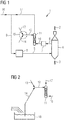
- FIG. 1 schematically shows an example of a device 1 according to the invention for reducing metal oxides 2 to metallized material 3 in a reduction unit 4.
- Metal oxides 2 are fed into the reduction unit 4, here a fixed bed reactor, at the top. They pass through the reduction shaft of the fixed bed reactor following the force of gravity, whereby they are reduced by contact in countercurrent with hot reducing gas introduced via the reducing gas supply line 5.
- the metallized material 3 - for example sponge iron - is removed from the reduction unit at the bottom - special discharge devices are not shown separately for the sake of clarity.
- the used reducing gas is discharged as so-called top gas from the top of the reduction unit 4 via a top gas discharge line 6 and into a Dry dedusting device 7 passed.
- the reducing gas is prepared in a reformer 8 by catalytic reforming of a raw gas mixture, at least on the basis of gaseous hydrocarbons - in the case of this example natural gas - and of dry-dusted top gas.
- the raw gas mixture is fed to the reformer via the raw gas feed line 9.
- the reducing gas prepared in the reformer 8 is fed to the reduction unit 4 via the reducing gas supply line 5 starting from the reformer 8.
- a dedusting line 10 extends from the dry dedusting device 7, through which dry dedusted top gas intended for the preparation of the raw gas mixture is led into the saturator 11 - here a packed column.
- the water vapor content of the dry, dedusted top gas is set in the saturator 11 by flowing through it in countercurrent with mass and heat exchange with saturation water.
- the saturation water is supplied to the saturator 11 via the saturation water supply line 12.
- An adjusting device 15 for adjusting the temperature of the saturation water by mixing hot water with cold water is provided.
- the hot water has a higher temperature than the cold water; the temperature of the saturation water is set to a target value by mixing hot water and cold water.
- the water basin 18 can be filled, for example, by introducing warm water returns from other points in the process for reducing metal oxides, indicated by 3 line openings on the left edge of the water basin.
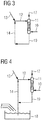
- FIG 3 For the sub-area Figure 1 around the saturator 11 Figure 3 with more details on how the hot water is drained from the saturator.
- a saturator waste water line 19 emanating from the saturator 11 is shown, which in turn opens into the hot water supply line 14.
- the saturator waste water line 19 serves to discharge saturator waste water from the saturator 11.
- the saturator wastewater will not be like in Figure 5 shown schematically, completely introduced into a water basin before it is fed to the saturator for use as warm water as a mixture with the other warm water returns. Instead, the saturator wastewater is used as hot water immediately after leaving the saturator.
- a partial flow, resulting from water condensation of the top gas and cold water supply, is discharged to a water basin, which is in Figure 3 but is not shown separately.
- FIG 4 shows more clearly an embodiment in which the hot water variants from Figure 2 and 3 are shown united at the same time.
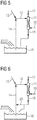
- FIG. 5 separately shows the detail that the saturator sewer line 19 has an opening into the water basin 18. Part of the hot water will therefore be saturator wastewater.
- Figure 6 shows an embodiment in which the variants of Figures 4 and 5 are united - the saturator sewer pipe has an opening into the water basin 18, and from the saturator sewer pipe 19
- a return line 20 branches off and opens into the hot water supply line 14.
- the branch and the mouth of the return line 20 are only at a slight height difference in order to reduce the effort required to overcome pressure differences that occur as a result of height differences.
- FIG. 7 shows an embodiment in a to Figure 1 analogous representation in which desulphurisation of the top gas also takes place during dry dedusting.
- a desulfurization device 21 is present in the top gas discharge line 6;
- this desulfurization device serves to introduce a solid adsorbent 22 into the flow of the top gas; it can be, for example, an addition pipe through which the adsorbent 22 is introduced into the top gas discharge line 6.
- the adsorbent is separated and there adsorbs sulfur or sulfur compounds, for example hydrogen sulfide H2S, from the top gas.
- FIG 8 shows an embodiment in a to Figure 1 analogous representation in which desulphurisation of the top gas also takes place after dry dedusting.
- a desulfurization device 23 is provided in the dedusting line 10.
- An optionally available bypass for operating situations in which at least a portion of the dry, dedusted top gas should not pass through the desulfurization device 23 is shown in dashed lines.
- the desulfurization device 23 operates, for example, on the basis of zinc oxide ZnO; a container containing zinc oxide is flowed through by the dry, dedusted top gas, which is desulphurized.
- FIG 9 shows an embodiment in a to Figure 1 analogous representation in which the temperature of the top gas is reduced before the dry dedusting.
- the temperature of the top gas is reduced by indirect heat exchange in a heat recovery system 24 - in the illustrated case with an indirect heat exchanger - in the top gas discharge line 6.
- the temperature of the top gas can be reduced before the dry dedusting by injecting water or a combination of indirect heat exchanger and water injection.
- the separate illustration of a water injection device instead of or in addition to the heat recovery system 24 is dispensed with for the sake of clarity.
- the temperature of the top gas can be reduced before the dry dedusting by supplying cooling gas into the flow of the top gas.
- a separate illustration of a cooling gas inlet instead of or in addition to the heat recovery system 24 and / or the water injection device is dispensed with for the sake of clarity.
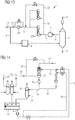
- Figure 10 shows an embodiment in a to Figure 1 analogous representation in which a subset of the top gas - optionally dry dedusted - optionally after desulfurization, not shown for the sake of clarity - is fed to the reformer 8 as a fuel gas component for the catalytic reforming.
- the energy for reforming is provided by burning a fuel gas; details of these known aspects are not shown for the sake of clarity.
- FIG 10 there is a fuel gas component line 25 which emanates from the dedusting line 10 and opens into a fuel gas supply line 26 for supplying fuel gas into the reformer 8.
- a gas cooling device can be present in the fuel gas component line 25, or an optionally existing branch of the fuel gas component line; this is not shown for the sake of clarity.
- the cooled fuel gas component can be combined with uncooled fuel gas components or fed to the reducing gas for cooling. If hot water is produced during cooling, it can be used as hot water for the saturator 11.
- Figure 11 shows an embodiment in a to Figure 1 analog representation in which two saturators 27a, 27b are connected in parallel.
- Figure 12 shows in to Figure 11 A largely analogous representation of an embodiment in which, unlike in the previous figures, not the entire subset of the dry, dedusted top gas that is provided for the preparation of the reducing gas is used to adjust its water vapor content to a saturator - the two saturators 27a, 27b connected in parallel are also possible - is fed.
- a portion of the partial amount of the dry dedusted top gas, which is provided for the preparation of the reducing gas is not subjected to any adjustment of the water vapor content in a saturator, but is passed in a bypass 28 to the saturators 27a, 27b.
- the remainder of the partial amount is subjected to adjustment of the water vapor content in the saturators 27a, 27b.
- the portion and the remainder of the subset are then combined.
- the resulting increase in temperature compared to the temperature of the rest is advantageous for the necessary feed into downstream compressors.
- Figure 13 shows in one too Figure 12 A largely analogous representation of a compressor 29 present in the saturated gas line 17 Figure 12
- the bypass 28 already discussed opens into the saturated gas line 17 upstream of the compressor 29.
- Dashed lines as optionally available are a return of a portion of the dry, dedusted saturated top gas heated by compression into the gas flow fed to the compression for the purpose of increasing the temperature in this gas flow.
- Figure 14 shows a section from a device according to the invention, the reduction unit, reformer and dry dedusting not being shown for the sake of clarity. Reference symbols that have already been used are possibly used for the same device parts.
- a dry dedusted top gas is fed through the dedusting line 10 to the saturator 11.
- a bypass 28 extends from the dedusting line 10, through which a portion is led past the saturator. The remainder is introduced into the saturator through the dedusting line 10.
- several saturators could also be connected in parallel.
- the pack is shown schematically with a section marked by an X.
- a demister is shown schematically by a narrow hatched zone at the upper end of the saturator.
- the saturated top gas is discharged from the saturator 10 via the saturated gas line 17.
- the saturator waste water is discharged from the saturator 11 through the saturator waste water line 19.
- An optionally available degasser 30 with an associated air supply 31 is shown in the saturator waste water line 19. Behind the degasser, the saturator waste water line opens into a water basin 18 into which degassed saturator waste water is introduced.
- a seal gas cooler line 32 and a reformed gas cooler line 33 - for guiding process water from a cooler for reformed gas - through which warm process water is introduced into the water basin 18, each with a degasser
- a device part 34 is also shown which can be a control valve or a siphon seal. It can also be seen how a return line 20 emanates from the saturator waste water line 19 and opens into the hot water supply line 14 downstream of a pump.
- hot water is fed to the saturator waste water via the hot water supply line 14.
- the hot water supply line 14 arises from the water basin 18.
- the combined quantities are supplied to the saturator together with cold water from the cold water supply line 13 via the saturation water supply line 12.
- the cold water supply line 13 branches off from the hot water supply line 14. This contains a heat exchanger for cooling the hot water - this produces cold water which is fed to the saturator 11 together with saturator waste water and hot water from the hot water supply line 13 as saturation water via the saturation water supply line 12.
- pumps and control valves are shown in the various lines.
- the distribution of the saturation water in the saturator 11 is shown schematically with indicated distribution nozzles.
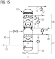
- FIG. 15 shows a section from a device according to the invention, the reduction unit, reformer and dry dedusting not being shown for the sake of clarity. Reference symbols that have already been used are possibly used for the same device parts.
- Desulphurization takes place after the dry dedusting, top gas which has been dry dedusted is passed through the dedusting line 10 to the wet desulfurization saturation unit 35 fed.
- the wet desulfurization saturation unit 35 In the upper part of the wet desulphurisation saturation unit 35 there is a saturator 36, in the lower part a wet desulphurisation unit 37. Gas entering the saturator 36 from the wet desulphurisation unit 37 is shown with dotted arrows.
- the wet desulphurisation unit 37 has a supply line 38, discharge line 39, and recycling line 40 including a pump for supplying fresh, discharging used, and recycling used desulphurisation liquid.
- the saturator has saturation water supply line 12, saturator waste water line 19 and return line 20. Via a feed line 41, saturator waste water can be fed into the feed line 38 for desulfurization liquid.
- An optionally available bypass line 42 starting from the dedusting line 10 opens into the wet desulfurization saturation unit 35 at the end of the wet desulfurization unit 37 on the saturator side.
- the amount of dry, dedusted top gas fed to both the wet desulphurization unit 37 and the saturator 36 can also be regulated; if necessary, only saturation, but no desulfurization, is necessary for the reformer.
- a desulfurized, saturated top gas is discharged from the wet desulfurization saturation unit 35 via the saturated gas line 17.
Description
Reduktionsgasgewinnung aus gesättigtem TopgasExtraction of reducing gas from saturated top gas
Die Anmeldung betrifft ein Verfahren und eine Vorrichtung zur Reduktion von Metalloxiden zu metallisiertem Material durch Kontakt mit heißem Reduktionsgas, wobei ein trocken entstaubtes Topgas anfällt, das gemeinsam mit gasförmigen Kohlenwasserstoffen zur Herstellung des Reduktionsgases katalytisch reformiert wird.The application relates to a method and a device for reducing metal oxides to metallized material by contact with hot reducing gas, a dry, dust-free top gas being obtained which is catalytically reformed together with gaseous hydrocarbons to produce the reducing gas.
Verfahren zur Direktreduktion von Eisenoxidträgern mittels eines durch Reformierung von Erdgas hergestellten Reduktionsgases sind bekannt, beispielsweise das MIDREX®-Verfahren wie in
Eine im Reformer ablaufende Reaktion ist
CH4 + H2O → CO + 3 H2
A reaction taking place in the reformer is
CH 4 + H 2 O → CO + 3 H 2
Entsprechend ist der Wasserdampfgehalt des zu reformierenden Rohgasgemischs ein bestimmender Faktor.Accordingly, the water vapor content of the raw gas mixture to be reformed is a determining factor.
Eine weitere im Reformer ablaufende Reaktion ist:
CH4 + CO2 → 2 CO + 2 H2
Another reaction taking place in the reformer is:
CH 4 + CO 2 → 2 CO + 2 H 2
CO2 wird beispielsweise in das zu reformierende Rohgasgemisch eingebracht, indem bei der Direktreduktion aus dem Reduktionsschacht abgezogenes Topgas nach Aufbereitung Erdgas zugemischt wird.For example, CO 2 is introduced into the raw gas mixture to be reformed by adding natural gas to the top gas withdrawn from the reduction shaft during direct reduction after processing.
Das aus dem Reduktionsschacht abgezogene Topgas ist sehr staubbeladen. Daher ist eine Entstaubung notwendig, einerseits zur Vermeidung von staubbedingtem Verschleiß von Vorrichtungen wie Kompressoren und Leitungen, die zur Rezyklierung des Topgases - als Bestandteil des Rohgasgemisches für den Reformer und darauffolgend als Bestandteil des Reduktionsgases für den Reduktionsschacht - notwendig sind, zur Vermeidung von staubbedingtem Verschleiß im Reformer, und andererseits zur Vermeidung von Anlagerungen des Staubes, sowie zur Vermeidung von Behinderung der Reformierung im Reformer.The top gas withdrawn from the reduction shaft is very dusty. Therefore dedusting is necessary, on the one hand to avoid dust-related wear of devices such as compressors and lines that are necessary for recycling the top gas - as part of the raw gas mixture for the reformer and subsequently as part of the reducing gas for the reduction shaft - to avoid dust-related wear in the reformer, and on the other hand to avoid accumulation of dust, as well as to avoid obstruction of the reforming in the reformer.
Die Anwendung von Nassentstaubung - beispielsweise mittels Venturiwäschern - und von Trockenentstaubung sind bekannt.The use of wet dedusting - for example by means of venturi scrubbers - and dry dedusting are known.
Bei der Nassentstaubung ist nachteilig, dass große Prozesswassermengen unter hohem Druck benötigt werden, welche im direkten Kontakt mit den Prozessgasen stehen. Der vom Gas abgeschiedene Staub fällt als nasser Schlamm in einem Klassierer beziehungsweise einem Eindicker an und muss aufwändig weiterbehandelt werden.The disadvantage of wet dedusting is that large amounts of process water are required under high pressure, which are in direct contact with the process gases. The dust separated from the gas accumulates as wet sludge in a classifier or a thickener and has to be further treated in a complex manner.
Bei der Trockenentstaubung ist nachteilig, dass die Temperatur des Topgases beim Entstaubungsschritt selbst praktisch nicht reduziert wird, und der Wasserdampfgehalt des Topgases entsprechend nicht durch Kondensation reduziert wird. Entsprechend weist ein derartig entstaubtes Topgas einen Wasserdampfgehalt auf, der für spätere Reformierung ungünstig hoch und schwankend ist. Eine auf die Trockenentstaubung folgende Kühlung ist daher notwendig, um einen Teil des Wasserdampfes zu kondensieren und auf einen kontrollierten Wert zu halten.
Diese beiden Patentanmeldungen sind relevante Beispiele für den Stand der Technik.These two patent applications are relevant examples of the prior art.
Es ist die Aufgabe der vorliegenden Anmeldung, ein Verfahren und eine Vorrichtung bereitzustellen, das bei Trockenentstaubung eine einfache, wenig aufwändige und zügig auf verschiedene Anforderungen der Verfahrensführung reaktionsfähige Einstellung des Wasserdampfgehaltes erlaubt. Ebenso soll eine zur Erreichung dieser Ziele fähige Vorrichtung bereitgestellt werden.It is the object of the present application to provide a method and a device which, in the case of dry dedusting, allows the water vapor content to be set in a simple, inexpensive and rapid manner that is responsive to various requirements of the process management. Likewise, a device capable of achieving these goals is to be provided.
Diese Aufgabe wird gelöst durch ein Verfahren zur Reduktion von Metalloxiden zu metallisiertem Material durch Kontakt mit heißem Reduktionsgas, wobei ein Topgas anfällt, wobei Trockenentstaubung des Topgases stattfindet, und wobei das Reduktionsgas zumindest zum Teil durch katalytische Reformierung eines Rohgasgemischs erhalten wird,
wobei das Rohgasgemisch zumindest auf Basis von
- gasförmigen Kohlenwasserstoffen, bevorzugt Erdgas, und von
- zumindest einer Teilmenge des trocken entstaubten Topgases
dadurch gekennzeichnet, dass
der Wasserdampfgehalt des für die Zubereitung des Rohgasgemisches bestimmten trocken entstaubten Topgases entweder nur in einem Sättiger im Gegenstrom mit Sättigungswasser, oder auch in einem Sättiger im Gegenstrom mit Sättigungswasser, eingestellt wird,
wobei die Temperatur des Sättigungswassers unter Vermischung von Kaltwasser mit einem Warmwasser, das eine höhere Temperatur als das Kaltwasser hat, zur Herstellung des Sättigungswassers auf einen Zielwert eingestellt wird, und eine Portion des für die Zubereitung des Rohgasgemisches bestimmten trocken entstaubten Topgases in einem Bypass (28) an dem Sättiger (11) vorbeigeführt wird, in dem der Rest des für die Zubereitung des Rohgasgemisches bestimmten trocken entstaubten Topgases Einstellung des Wasserdampfgehaltes unterworfen wird, und nachfolgend eine Vereinigung der Portion und des Restes erfolgt.This object is achieved by a method for reducing metal oxides to metallized material by contact with hot reducing gas, with a top gas being produced, with Dry dedusting of the top gas takes place, and the reducing gas is obtained at least in part by catalytic reforming of a raw gas mixture,
wherein the raw gas mixture at least on the basis of
- gaseous hydrocarbons, preferably natural gas, and of
- at least a portion of the dry dedusted top gas
characterized in that
the water vapor content of the dry, dedusted top gas intended for the preparation of the raw gas mixture is set either only in a saturator in countercurrent with saturation water, or also in a saturator in countercurrent with saturation water,
wherein the temperature of the saturation water is set to a target value by mixing cold water with hot water, which has a higher temperature than the cold water, for the production of the saturation water, and a portion of the dry, dedusted top gas intended for the preparation of the raw gas mixture in a bypass (28 ) is passed past the saturator (11), in which the remainder of the dry, dedusted top gas intended for the preparation of the raw gas mixture is subjected to adjustment of the water vapor content, and subsequently the portion and the remainder are combined.
Die Einstellung des Wasserdampfgehaltes beziehungsweise die Einstellung des Zielwertes für die Temperatur des Sättigungswassers kann eine Steuerung oder eine Regelung sein.The setting of the water vapor content or the setting of the target value for the temperature of the saturation water can be a control or regulation.
Der Zielwert für die Temperatur des Sättigungswassers kann eine bestimmte Temperatur oder ein Temperaturbereich sein, genannt Temperatur-Zielbereich. Ebenso kann die Einstellung des Wasserdampfgehaltes einen bestimmten Wasserdampfgehalt zum Ziel haben oder einen Wertebereich, genannt Wasserdampf-Zielbereich. Kaltwasser bezeichnet zur Einführung in den Sättiger vorgesehenes Wasser, das eine geringere Temperatur als das Warmwasser hat.The target value for the temperature of the saturation water can be a certain temperature or a temperature range, called the temperature target range. The setting of the water vapor content can also aim at a specific water vapor content or a range of values, called the water vapor target range. Cold water refers to water intended for introduction into the saturator, which has a lower temperature than the hot water.
Warmwasser hat eine höhere Temperatur als das Kaltwasser. Es kann sich um ein warmes - in dem Sinne, dass es eine höhere Temperatur als das Kaltwasser hat - Prozesswasser handeln, das in dem Verfahren zur Reduktion von Metalloxiden an anderer Stelle anfällt - beispielsweise um Wasser, welches zum Kühlen von heißen Gasen innerhalb des Reduktionsverfahrens verwendet wird, wie für die Kühlung von Sealgas im Sealgaskühler oder einer Teilmenge des reformierten Gases in einem Gaskühler, und deren warme Wasserrückläufe - häufig auch Rein-Prozesswasser genannt -in einem Wasserbecken gesammelt werden; auch Sättigerabwasser kann in dieses Wasserbecken eingeleitet werden.
Es ist möglich, aus diesem Wasserbecken mit vereinigten warmen Wasserrückläufen eine Wassermenge einer Kühlung - beispielsweise in Wärmetauschern - zuzuführen und nach der Kühlung als Kaltwasser zu verwenden.Hot water has a higher temperature than cold water. It can be warm process water - in the sense that it has a higher temperature than cold water - that occurs elsewhere in the process for reducing metal oxides - for example, water that is used to cool hot gases within the reduction process is used, such as for the cooling of seal gas in the seal gas cooler or a subset of the reformed gas in one Gas coolers and their warm water returns - often also called pure process water - are collected in a water basin; saturator wastewater can also be discharged into this water basin.
It is possible from this water basin with combined warm water returns to supply a quantity of water to a cooling system - for example in heat exchangers - and to use it as cold water after cooling.
Im Sättiger wird der Wasserdampfgehalt des trocken entstaubten Topgases im Gegenstrom mit Sättigungswasser eingestellt.In the saturator, the water vapor content of the dry, dedusted top gas is set in countercurrent with the saturation water.
Der Sättiger ist beispielsweise eine vom Sättigungswasser im Gegenstrom zum trocken entstaubten Topgas durchströmte Packungskolonne. Eine solche Packungskolonne weist typischerweise einen Wasserverteiler oberhalb der zu benetzenden Packung, letztere bestehend aus Füllkörpern oder einer strukturierten Packung oder ähnlichem auf, um einen guten Wärme- und Stoffaustausch zu gewährleisten. Oberhalb des Wasserverteilers oder am Austritt der Packungskolonne ist typischerweise ein Tröpfchenabscheider - Demister - eingebaut um den Mitriss von Tröpfchen mit dem Gasstrom zu verhindern.The saturator is, for example, a packed column through which the saturation water flows in countercurrent to the dry, dedusted top gas. Such a packed column typically has a water distributor above the packing to be wetted, the latter consisting of random packings or structured packing or the like, in order to ensure good heat and mass transfer. A droplet separator - demister - is typically installed above the water distributor or at the outlet of the packed column in order to prevent droplets from being carried along with the gas flow.
Unter Metalloxiden werden bevorzugt Eisenoxide beziehungsweise eisenoxid-hältige Einsatzstoffe verstanden. Weiters können aber auch, gemäß Richardson-Jeffes-Diagramm, beispielsweise oxidische Erze von Nickel, Kupfer, Blei, Kobalt, reduziert werden.Metal oxides are preferably understood to mean iron oxides or starting materials containing iron oxide. Furthermore, according to the Richardson-Jeffes diagram, for example oxidic ores of nickel, copper, lead, and cobalt can be reduced.
Die Reduktion ist bevorzugt eine Direktreduktion.The reduction is preferably a direct reduction.
Das metallisierte Material ist bevorzugt das Produkt der Direktreduktion.The metallized material is preferably the product of direct reduction.
Die Reduktion der Metalloxide erfolgt bevorzugt zu weitgehend metallisiertem Metall - das heißt, dass ein Metallisierungsgrad von beispielsweise typischerweise größer gleich 90% vorliegt, bevorzugt größer gleich 92% - , beispielsweise Eisenschwamm, auch genannt DRI direct reduced iron. Der Metallisierungsgrad ist das Verhältnis zwischen metallischem Eisen und Gesamteisen.The metal oxides are preferably reduced to largely metallized metal - that is, a degree of metallization of, for example, typically greater than or equal to 90%, preferably greater than or equal to 92% -, for example sponge iron, also called DRI direct reduced iron. The degree of metallization is the ratio between metallic iron and total iron.
Das Produkt der Direktreduktion von eisenoxid-hältigen Einsatzstoffen, beispielsweise DRI oder HDRI, wird bevorzugt heiß brikettiert, beispielsweise zu hot briquetted iron HBI verarbeitet. Es kann aber auch im heißen Zustand aus dem Reduktionsschacht, in dem die Direktreduktion stattfindet, ausgetragen, und direkt im Stahlwerk genutzt werden - beispielsweise durch Zugabe in heißem Zustand in einen Elektrolichtbogenofen.The product of the direct reduction of iron oxide-containing feedstocks, for example DRI or HDRI, is preferably hot briquetted, for example processed into hot briquetted iron HBI. However, it can also be discharged in the hot state from the reduction shaft in which the direct reduction takes place and used directly in the steelworks - for example by adding it in a hot state to an electric arc furnace.
Die Trockenentstaubung erfolgt beispielsweise mittels Gewebefiltern wie beispielsweise Tuch- oder Schlauchfiltern. Für eine Grobentstaubung vor den Gewebefiltern kann auch eine Grobentstaubung auf Basis von beispielsweise Zyklon oder Staubsack vorgesehen sein.
Es kann das gesamte Topgas trocken entstaubt werden, oder ein mengenmäßiger Anteil des Topgases.Dry dedusting takes place, for example, by means of fabric filters such as cloth or bag filters. For coarse dedusting in front of the fabric filters, coarse dedusting based on, for example, a cyclone or dust bag can also be provided.
The entire top gas can be dedusted dry, or a quantitative proportion of the top gas.
Das Reduktionsgas kann vollständig durch katalytische Reformierung eines Rohgasgemisches erhalten werden; es kann aber auch Bestandteile enthalten, die nicht aus der katalytischen Reformierung des Rohgasgemisches stammen.The reducing gas can be obtained entirely by catalytic reforming of a raw gas mixture; but it can also contain components that do not come from the catalytic reforming of the raw gas mixture.
Das Rohgasgemisch wird zumindest auf Basis von gasförmigen Kohlenwasserstoffen und von zumindest einer Teilmenge des trocken entstaubten Topgases zubereitet.The raw gas mixture is prepared at least on the basis of gaseous hydrocarbons and of at least a partial amount of the dry dedusted top gas.
Die Formulierung "auf Basis von gasförmigen Kohlenwasserstoffen, bevorzugt Erdgas," umfasst sowohl einen einzelnen gasförmigen Kohlenwasserstoff, als auch Gasgemische, die einen oder mehrere gasförmige Kohlenwasserstoffe enthalten. Ein solches Gasgemisch ist beispielsweise Erdgas.
Es kann das gesamte trocken entstaubte Topgas verwendet werden, um das Rohgasgemisch zuzubereiten; es kann aber auch nur eine Teilmenge des trocken entstaubten Topgases dazu verwendet werden.The phrase “based on gaseous hydrocarbons, preferably natural gas,” encompasses both a single gaseous hydrocarbon and gas mixtures which contain one or more gaseous hydrocarbons. Such a gas mixture is, for example, natural gas.
All of the dry, dust-free top gas can be used to prepare the raw gas mixture; however, only a portion of the dry, dedusted top gas can be used for this purpose.
Der Wasserdampfgehalt des für die Zubereitung des Rohgasgemisches bestimmten trocken entstaubten Topgases wird in einem Sättiger im Gegenstrom mit Sättigungswasser eingestellt.The water vapor content of the dry dedusted top gas intended for the preparation of the raw gas mixture is set in a saturator in countercurrent with saturation water.
Bei der erfindungsgemäßen Verfahrensführung wird nach der Trockenentstaubung der Wasserdampfgehalt des für die Zubereitung des Rohgasgemisches bestimmten Topgases auf einen gewünschten Wert beziehungsweise einen gewünschten Wertebereich eingestellt. Erfindungsgemäß findet dazu als ein Verfahrensschritt statt, die Temperatur des Sättigungswassers unter Vermischung von Kaltwasser mit einem Warmwasser zur Herstellung des Sättigungswassers auf einen Zielwert einzustellen. In der Regel hat trocken entstaubtes Topgas einen Wasserdampfgehalt von etwa 20 bis 30 Volums%. Im Falle einer Kühlung durch Wassereindüsung vor der Trockenentstaubung kann der Wasserdampfgehalt auch auf über 30 Volums% , beispielsweise 32 Volums%, ansteigen.
Ziel ist es, einen für eine spätere Reformierung günstigen Wasserdampfgehalt einzustellen.In the procedure according to the invention, after the dry dedusting, the water vapor content of the top gas intended for the preparation of the raw gas mixture is set to a desired value or a desired range of values. According to the invention, a method step for this purpose is to set the temperature of the saturation water to a target value while mixing cold water with hot water to produce the saturation water. As a rule, dry, dust-free top gas has a water vapor content of around 20 to 30% by volume. In the event of cooling by water injection before dry dedusting, the water vapor content can also rise to over 30% by volume, for example 32% by volume.
The aim is to set a water vapor content that is favorable for later reforming.
Der Zielwert für die Temperatur des Sättigungswassers wird so gewählt, dass sich nach der Wechselwirkung mit dem trocken entstaubten Topgas ein für die spätere Reformierung günstiger Wasserdampfgehalt im Topgas ergibt.The target value for the temperature of the saturation water is selected in such a way that, after the interaction with the dry dedusted top gas, a water vapor content in the top gas that is favorable for the subsequent reforming results.
Der Wasserdampfgehalt des für die Zubereitung des Rohgasgemisches bestimmten trocken entstaubten Topgases wird in einem Sättiger im Gegenstrom mit Sättigungswasser eingestellt.
Der Wasserdampfgehalt des zur Zubereitung des Rohgasgemisches bestimmten trocken entstaubten Topgases wird dabei entweder nur in einem Sättiger im Gegenstrom mit Sättigungswasser eingestellt, oder er wird - zusätzlich zu weiteren Maßnahmen - auch in einem Sättiger im Gegenstrom mit Sättigungswasser eingestellt. Zur Einstellung des Wasserdampfgehaltes können also zusätzlich auch weitere Maßnahmen wie die Zugabe von Dampf oder die Einspritzung von flüssigem Wasser, beispielsweise mittels Einstoff- oder Zweistoffdüsen - erfolgen. Beispielsweise können solche zusätzlichen Maßnahmen beim Anfahren der Anlage hilfreich sein. Sie können auch hilfreich sein, um Feinregulierung oder schnellere - im Vergleich zum Sättiger - Regelung des Wasserdampfgehaltes zu erzielen. Das könnte beispielsweise gewünscht sein zur Problembehebung oder -vermeidung beim Reformerbetrieb, beispielsweise zur Vermeidung von Kohlenstoffablagerungen am Reformerkatalysator. Mittels Sättiger sollen zumindest 70 % des Wasserdampfgehaltes beigetragen werden.The water vapor content of the dry, dedusted top gas intended for the preparation of the raw gas mixture is adjusted in a saturator in countercurrent with saturation water.
The water vapor content of the dry, dedusted top gas intended for the preparation of the raw gas mixture is either only set in a saturator in countercurrent with saturation water, or - in addition to further measures - it is also set in a saturator in countercurrent with saturation water. To adjust the water vapor content, additional measures such as the addition of steam or the injection of liquid water, for example by means of single-substance or two-substance nozzles, can also be carried out. For example, such additional measures can be helpful when starting up the plant. They can also be helpful in order to achieve fine adjustment or faster - compared to the saturator - regulation of the water vapor content. This could be desired, for example, to solve or avoid problems when operating the reformer, for example to avoid carbon deposits on the reformer catalyst. At least 70% of the water vapor content should be contributed by means of a saturator.
Zur Einstellung der Temperatur des Sättigungswassers können zusätzlich auch weitere Maßnahmen wie Kühlung oder Heizung erfolgen.To set the temperature of the saturation water, additional measures such as cooling or heating can also be carried out.
Aufgrund der erfindungsgemäßen Einflussnahme auf den Wasserdampfgehalt lässt sich die Gefahr von Kohlenstoffablagerungen am Katalysator im Reformer vermindern, was seine Lebensdauer und Verfügbarkeit erhöht. Besonders günstig ist der Effekt beim Anfahren einer Anlage.Due to the influence according to the invention on the water vapor content, the risk of carbon deposits on the catalyst in the reformer can be reduced, which increases its service life and availability. The effect is particularly favorable when starting up a system.
Im Vergleich zu einer herkömmlichen Verfahrensführung, beispielsweise mit Nassentstaubung, ist bei der erfindungsgemäßen Verfahrensführung vorteilhaft, dass im Reduktionsgas höhere Wasserstoff H2 zu Kohlenmonoxid CO Verhältnisse H2/CO einstellbar sind. Der Wasserdampfgehalt bei der Reformierung bestimmt das Verhältnis von CO und H2 im Reduktionsgas; durch die Einstellung des Wasserdampfgehaltes im entstaubten Topgas - gegebenenfalls in einem im Vergleich zu herkömmlicher Verfahrensführung weiteren Bereich - lässt sich somit der Ablauf der Reduktion beeinflussen. Wasserstoffreduktion ist schneller und überwiegend endotherm, Kohlenmonoxidreduktion ist langsamer als Wasserstoffreduktion und überwiegend exotherm. Flexible Einstellbarkeit erleichtert ökonomische Verfahrensführung. Bei schnell erreichter höherer Temperatur des Sättigungswassers und damit einhergehender höherer Temperatur des aus dem Sättiger austretenden trocken entstaubten Topgases kann schnell ein bestimmter ausreichend hoher Wasserdampfgehalt erzielt werden.In comparison to a conventional procedure, for example with wet dedusting, it is advantageous in the procedure according to the invention that higher hydrogen H 2 to carbon monoxide CO ratios H 2 / CO can be set in the reducing gas. The water vapor content during reforming determines the ratio of CO and H2 in the reducing gas; By setting the water vapor content in the dedusted top gas - possibly in a wider range compared to conventional process management - the course of the reduction can thus be influenced. Hydrogen reduction is faster and predominantly endothermic, carbon monoxide reduction is slower than hydrogen reduction and predominantly exothermic. Flexible adjustability facilitates economic process management. When the higher temperature of the saturation water is reached quickly and the associated higher temperature of the from the saturator escaping dry dust-free top gas, a certain sufficiently high water vapor content can be achieved quickly.
Bestehende Anlagen mit Nassentstaubung können einfach auf Trockenentstaubung umgerüstet und so für die Durchführung des Verfahrens vorbereitet werden. Das Ersetzen von Venturiwäschern durch Trockenfilter erfordert nur relativ geringe Investitionen. Vorteilhaft ist im Vergleich zu einem Betrieb mit Nassentstaubung auch, dass aus anderen Stellen des Verfahrens zur Reduktion von Metalloxiden stammende Abwässer mit hohem Feststoffanteil - beispielsweise aus der Entstaubung von Gasen aus der Heißbrikettierung, aus der Entstaubung von Gasen aus Heißtransportvorrichtungen, aus der Entstaubung von Sperrgasen aus Reduktionsreaktoren - nicht durch gemeinsame Aufarbeitung mit vergleichsweise wenig Feststoffe führendem Abwasser verdünnt werden. Das macht die Aufarbeitung solcher Abwässer einfacher.Existing systems with wet dedusting can easily be converted to dry dedusting and thus prepared for the implementation of the process. Replacing venturi scrubbers with dry filters requires relatively little investment. In comparison to operation with wet dedusting, it is also advantageous that waste water with a high solid content originating from other points in the process for the reduction of metal oxides - for example from the dedusting of gases from hot briquetting, from the dedusting of gases from hot transport devices, from the dedusting of barrier gases from reduction reactors - cannot be diluted by joint processing with wastewater containing comparatively few solids. This makes the processing of such wastewater easier.
Gegenüber einer Nassentstaubung bietet sich durch die Trockenentstaubung der Vorteil, dass Staub im Gegensatz zu Schlamm vor einer Weiterverwendung nicht aufwändig getrocknet werden muss.Compared to wet dedusting, dry dedusting has the advantage that, unlike sludge, dust does not have to be laboriously dried before it can be used again.
Gegenüber einer Nassentstaubung bietet sich durch die Trockenentstaubung der Vorteil, dass weniger Druckverlust auftritt, und entsprechend für folgende Kompressoren weniger Leistung und Stromverbrauch notwendig ist zur Erzielung gewünschter Drücke.Compared to wet dedusting, dry dedusting has the advantage that there is less pressure loss, and accordingly less power and power consumption is required for the following compressors to achieve the desired pressures.
Nach einer bevorzugten Ausführungsform werden Kaltwasser und Warmwasser einer Regelung unterworfen vermischt, die auf Basis von
- Temperaturmessung des Sättigungswassers,
und/oder - Temperaturmessung des gesättigten Topgases,
und - einer Sollwertvorgabe für die Temperatur und/oder den Wasserdampfgehalt des gesättigten Topgases und/oder einer Zielwertvorgabe für die Temperatur des Sättigungswassers
- Temperature measurement of the saturation water,
and or - Temperature measurement of the saturated top gas,
and - a target value specification for the temperature and / or the water vapor content of the saturated top gas and / or a target value specification for the temperature of the saturation water
Das aus dem Sättiger austretende trocken entstaubte Topgas wird gesättigtes Topgas genannt.The dry, dedusted top gas emerging from the saturator is called saturated top gas.
Die Temperatur des Sättigungswassers wird derart geregelt, dass die Temperatur und/oder der Wasserdampfgehalt des gesättigten Topgases einem Zielwert beziehungsweise einem Zielbereich entsprechen. Über die Temperatur ist thermodynamisch auch der Wasserdampfgehalt definiert.The temperature of the saturation water is regulated in such a way that the temperature and / or the water vapor content of the saturated top gas correspond to a target value or a target range. The water vapor content is also defined thermodynamically via the temperature.
Nach einer bevorzugten Ausführungsform ist der Zielwert 323 - 373 K, bevorzugt 338 - 363 K, wobei die beiden Grenzen jeweils mit eingeschlossen sind. Bei Betrieb des Verfahrens bei einem Druck von 1 barg ergibt sich ein möglicher Wasserdampfgehalt von 6-51 Volumsprozent Vol%; bei Betrieb bei 2 barg ergibt sich ein möglicher Wasserdampfgehalt von 4-34 Volumsprozent Vol%. Gewünscht sind Werte von 10 - 20 Vol% Wasserdampfgehalt.According to a preferred embodiment, the target value is 323-373 K, preferably 338-363 K, both limits being included in each case. When the process is operated at a pressure of 1 bar g, the result is a possible water vapor content of 6-51 percent by volume by volume; operating at 2 bar g results in a possible water vapor content of 4-34 percent by volume by volume. Values of 10-20% by volume of water vapor are desired.
Nach einer vorteilhaften Ausführungsform ist zumindest ein Teil des Warmwassers, das eine höhere Temperatur als das Kaltwasser hat, aus dem Sättiger abgeführtes Sättigerabwasser.
Da vorab eine Trockenentstaubung des Topgases erfolgt, ist das Sättigerabwasser für so eine Nutzung brauchbar. Ohne Trockenentstaubung vorab würde die als Schlamm mitgeführte Staubfracht die Nutzung als Sättigerabwasser erschweren oder verhindern.According to an advantageous embodiment, at least part of the hot water which has a higher temperature than the cold water is saturator waste water discharged from the saturator.
Since the top gas is dry-dedusted beforehand, the saturator wastewater can be used for such purposes. Without dry dedusting beforehand, the dust load carried along as sludge would make it difficult or impossible to use it as saturator wastewater.
Nach einer bevorzugten Variante wird der als Warmwasser genutzte Teil des Sättigerabwassers direkt nach dem Verlassen des Sättigers der Nutzung als Warmwasser zugeführt. Er wird also vor der Nutzung als Warmwasser nicht in ein Wasserbecken eingeleitet, und dort gegebenenfalls mit anderen warmen Wasserrückläufen aus anderen Stellen des Verfahrens zur Reduktion von Metalloxiden vereinigt, bevor er zur Nutzung als Warmwasser - gegebenenfalls als Gemisch mit den anderen warmen Wasserrückläufen - dem Sättiger zugeführt wird. Stattdessen wird das Sättigerabwasser direkt nach dem Verlassen des Sättigers der Nutzung als Warmwasser zugeführt.According to a preferred variant, the part of the saturator wastewater used as hot water is used as hot water immediately after leaving the saturator. Before it is used as hot water, it is not fed into a water basin, where it is combined with other warm water returns from other points in the process for reducing metal oxides, before it is used as warm water - possibly as a mixture with the other warm water returns - the saturator is fed. Instead, the saturator wastewater is used as hot water immediately after leaving the saturator.
Nach einer anderen Variante wird der als Warmwasser genutzte Teil des Sättigerabwassers in ein Wasserbecken eingeleitet - und dort gegebenenfalls mit anderen warmen Wasserrückläufen aus anderen Stellen des Verfahrens zur Reduktion von Metalloxiden vereinigt -, bevor er zur Nutzung als Warmwasser - gegebenenfalls als Gemisch mit den anderen warmen Wasserrückläufen - dem Sättiger zugeführt wird.According to another variant, the part of the saturator wastewater used as warm water is fed into a water basin - and there, if necessary, combined with other warm water returns from other points in the process for reducing metal oxides - before it is used as warm water - possibly as a mixture with the other warm water Water returns - fed to the saturator.
Im Sättiger wird der Wasserdampfgehalt des trocken entstaubten Topgases im Gegenstrom mit Sättigungswasser eingestellt. Nach der Wechselwirkung im Gegenstrom wird das sogenannte Sättigerabwasser aus dem Gegenstrombereich, in dem die Wechselwirkung stattfindet, abgeführt. Das Sättigerabwasser weist aufgrund der höheren Gaseintrittstemperatur in den Sättiger und der darin stattfindenden Kondensation eine höhere Temperatur als das Sättigungswasser am Eintritt in den Sättiger auf.In the saturator, the water vapor content of the dry, dedusted top gas is set in countercurrent with the saturation water. After the countercurrent interaction, the so-called saturator wastewater is discharged from the countercurrent area in which the interaction takes place. The saturator wastewater has a higher temperature than the saturation water at the inlet to the saturator due to the higher gas inlet temperature into the saturator and the condensation taking place therein.
Das Sättigerabwasser verlässt den Sättiger unter Druck
- hydrostatischer Druck plus Gasdruck des eingeleiteten entstaubten Topgases. Daher kann aus dem Sättiger abgeführtes Sättigerabwasser, welches unter diesem Druck steht, einfach mit Kaltwasser vermischt werden. Die Vermischung wird auch dadurch vereinfacht, dass sie in der unmittelbaren Nähe des Sättigers stattfinden kann - ohne große Höhenunterschiede und damit hydrostatische Drücke überwinden zu müssen. Entsprechend müssen Pumpen, die Sättigerabwasser via Vermischung mit Kaltwasser in den Sättiger rezirkulieren, nicht zur Überwindung großer Höhenunterschiede und/oder Druckverluste ausgelegt sein
- sie können kleiner sein und verbrauchen daher weniger Strom.
- hydrostatic pressure plus gas pressure of the introduced dedusted top gas. Therefore, saturator wastewater discharged from the saturator, which is under this pressure, can simply be mixed with cold water. Mixing is also simplified by the fact that it can take place in the immediate vicinity of the saturator - without having to overcome large differences in height and thus hydrostatic pressures. Accordingly, pumps that recirculate saturator wastewater into the saturator by mixing with cold water do not have to be designed to overcome large differences in height and / or pressure losses
- they can be smaller and therefore use less electricity.
Besonders günstig wirkt sich die erfindungsgemäße Verfahrensführung beim Anfahren einer Anlage aus, da eine schnelle Erhöhung der Temperatur des Sättigungswassers möglich ist, wenn verhältnismäßig viel Sättigerabwasser als Warmwasser zur Temperaturerhöhung dem Kaltwasser zugemischt wird. Das erspart beispielsweise Aufwand zur Temperaturerhöhung von Kaltwasser gegenüber einer Variante, bei der Warmwasser anderer Herkunft aus einem Wasserbecken entnommen wird, wobei gerade beim Anfahren einer Anlage einige Zeit benötigt werden würde, um das Wasser im Wasserbecken auf die gewünschte Temperatur zu bringen. Bei schnell erreichter höherer Temperatur des Sättigungswassers und damit einhergehender höherer Temperatur des aus dem Sättiger austretenden trocken entstaubten Topgases kann schnell ein bestimmter ausreichend hoher Wasserdampfgehalt erzielt werden.The procedure according to the invention has a particularly favorable effect when starting up a plant, since a rapid increase in the temperature of the saturation water is possible if a relatively large amount of saturator wastewater is added to the cold water as hot water to increase the temperature. This saves, for example, the effort of increasing the temperature of cold water compared to a variant in which hot water of a different origin is taken from a water basin, whereby some time would be required when starting up a system to bring the water in the water basin to the desired temperature. When the higher temperature of the saturation water is reached quickly and the associated higher temperature of the dry, dedusted top gas emerging from the saturator, a certain sufficiently high water vapor content can quickly be achieved.
Aufgrund von Kondensation von Wasserdampf im Sättiger übersteigt die Sättigerabwassermenge in der Regel die Menge des zugeführten Sättigungswassers; außerdem wird das Sättigungswasser auch unter Verwendung einer Menge von Kaltwasser gebildet. Daher wird in der Regel nicht das gesamte Sättigerabwasser mit Kaltwasser gemischt, um Sättigungswasser herzustellen; lediglich eine Teilmenge wird dem Kaltwasser zwecks Herstellung des Sättigungswassers zugemischt. Nicht direkt mit dem Kaltwasser gemischtes Sättigerabwasser kann in ein Becken für sauberes Prozesswasser beziehungsweise Rein-Prozesswasser geleitet werden, da aufgrund der vorhergehenden Trockenentstaubung des Topgases bei der Wechselwirkung im Gegenstrom im Sättiger praktisch keine Verschmutzung des Sättigungswassers erfolgt. Dabei kann es zweckmäßig sein, vor Einleitung in das Becken zu kühlen, denn das Sättigerabwasser steht gegebenenfalls unter einem erhöhten Druck und Temperatur, so dass infolge Entspannung bei der Einleitung in das Becken erhöhte Verdampfung auftreten könnte. Die fachgerechte Entsorgung oder Reinigung von verschmutztem Sättigerabwasser wäre wesentlich aufwändiger; bei Einleitung in bestehende Entsorgungsbeziehungsweise Reinigungssysteme für anderweitig anfallende Prozessabwässer müssten diese größer ausgelegt werden.
Nach Abkühlung des Sättigerabwassers kann es als Kaltwasser wiederverwendet werden; bei einer solchen Kreislaufführung werden diffuse CO-Emissionen des Verfahrens zur Reduktion von Metalloxiden vermindert.Due to condensation of water vapor in the saturator, the amount of saturator wastewater usually exceeds the amount of the supplied saturation water; in addition, the saturation water is also formed using a lot of cold water. Therefore, not all of the saturator wastewater is typically mixed with cold water to produce saturation water; only a partial amount is added to the cold water for the purpose of producing the saturation water. Saturator wastewater that is not mixed directly with the cold water can be fed into a basin for clean process water or pure process water, as due to the prior dry dedusting of the top gas with the interaction in countercurrent in the saturator, there is practically no contamination of the saturation water. It can be useful to cool before it is discharged into the basin, because the saturator wastewater may be under increased pressure and temperature, so that increased evaporation could occur as a result of relaxation when it is discharged into the basin. The professional disposal or cleaning of polluted saturator wastewater would be much more time-consuming; in the case of introduction into existing disposal or cleaning systems for otherwise occurring process wastewater, these would have to be designed larger.
After the saturator wastewater has cooled down, it can be reused as cold water; With such a cycle, diffuse CO emissions from the process for reducing metal oxides are reduced.
Die erfindungsgemäße Verfahrensführung bietet also den Vorteil, dass für eine Temperatureinstellung des Sättigungswassers benötigtes warmes Wasser nicht aufwändig erzeugt und/oder herangeschafft werden muss, sondern im Sättiger selbst anfällt - als Sättigerabwasser - und ohne großen Aufwand gegebenenfalls in unmittelbarer Nähe zum Sättiger für die Mischung genutzt werden kann.The procedure according to the invention thus offers the advantage that the warm water required for setting the temperature of the saturation water does not have to be generated and / or brought in at great expense, but is obtained in the saturator itself - as saturator waste water - and, if necessary, used for the mixture in close proximity to the saturator without great effort can be.
Je geringer die Sättigerabwassermenge ist, die zum Becken geführt wird, desto geringer ist auch die Menge an darin gelösten Gasbestandteilen. Diese geringeren Wassermengen können einfach in Entgasungsvorrichtungen weitgehend von darin gelösten Bestandteilen befreit und sicher entsorgt werden.The lower the amount of saturator wastewater that is led to the basin, the lower the amount of gas components dissolved in it. These smaller amounts of water can be largely freed from the dissolved constituents in degassing devices and safely disposed of.
Bei einer Umrüstung bestehender Anlagen mit Nassentstaubung auf Trockenentstaubung können gegebenenfalls vorhandene Rezirkulationspumpen am Venturiwäscher für die Zuführung des Sättigerabwassers zum Kaltwasser wiederverwertet werden, da sie auch für diese Aufgabe geeignet sein werden, wenn keine großen hydrostatischen Drücke überwunden werden müssen.When converting existing systems with wet dedusting to dry dedusting, existing recirculation pumps on the venturi scrubber can be reused for supplying the saturator wastewater to the cold water, as they will also be suitable for this task if no large hydrostatic pressures have to be overcome.
Nach einer vorteilhaften Ausführungsform erfolgt während und/oder nach der Trockenentstaubung Entschwefelung des Topgases. Beispielsweise kann vor der Trockenentstaubung ein festes Adsorptionsmittel in den Strom des Topgases eingebracht werden, an dem Schwefelwasserstoff H2S adsorbiert wird; Abscheidung aus dem Strom des Topgases erfolgt dann bei der Trockenentstaubung. Beispielsweise kann nach der Trockenentstaubung Entschwefelung auf Basis von Zinkoxid ZnO erfolgen, was für effiziente Durchführung Temperaturen von 473 - 723 K, bevorzugt 623 - 723 K, erfordert. Das Topgas hat in der Regel eine Temperatur von 623 - 673 K.According to an advantageous embodiment, desulfurization of the top gas takes place during and / or after the dry dedusting. For example, before the dry dedusting, a solid adsorbent can be introduced into the flow of the top gas on which hydrogen sulfide H 2 S is adsorbed; Separation from the flow of the top gas then takes place during dry dedusting. For example, after the dry dedusting, desulfurization based on zinc oxide ZnO can take place, which requires temperatures of 473-723 K, preferably 623-723 K, for efficient implementation. The top gas usually has a temperature of 623 - 673 K.
Entschwefelung nach der Trockenentstaubung kann auch mittels eines Nassverfahrens mit einer Entschwefelungsflüssigkeit - beispielsweise Reagenzien zur Entschwefelung enthaltendes Wasser - erfolgen, wie beispielsweise nach einem Reaktionsablauf
H2S + ½ O2 → H2O + S.
Desulfurization after the dry dedusting can also take place by means of a wet process with a desulfurization liquid - for example water containing reagents for desulfurization - such as after a reaction sequence
H 2 S + ½ O 2 → H 2 O + S.
Dabei kann ein einem ersten Schritt beispielsweise eine Absorption von Schwefelwasserstoff H2S in Wasser H2O erfolgen.In a first step, for example, an absorption of hydrogen sulfide H 2 S in water H 2 O can take place.
Die Entschwefelung mittels eines Nassverfahrens kann beispielsweise in einem Nassentschwefelungsaggregat vor dem Eintritt in den Sättiger erfolgen. Das Nassentschwefelungsaggregat kann dabei separat vom Sättiger ausgeführt sein. Das Nassentschwefelungsaggregat kann auch gemeinsam mit dem Sättiger in einem gemeinsamen Nassentschwefelungs-Sättigungs-Aggregat vorhanden sein, wobei das Gas zuerst die Nassentschwefelung durchläuft und dann den Sättiger.
Die Entschwefelung mittels eines Nassverfahrens kann auch im Sättiger erfolgen durch Eindüsung entsprechender Entschwefelungsflüssigkeit; beispielsweise kann ein Teil oder das ganze Sättigungswasser auch Reagenzien zur Entschwefelung enthalten.
Nach einer Ausführungsform kann Sättigerabwasser zumindest als Teilmenge der Entschwefelungsflüssigkeit genutzt werden.The desulfurization by means of a wet process can take place, for example, in a wet desulfurization unit before entering the saturator. The wet desulfurization unit can be designed separately from the saturator. The wet desulphurisation unit can also be present together with the saturator in a common wet desulphurisation / saturation unit, the gas first passing through the wet desulphurisation and then the saturator.
The desulphurisation by means of a wet process can also take place in the saturator by injecting the appropriate desulphurisation liquid; for example, some or all of the saturation water may also contain reagents for desulfurization.
According to one embodiment, saturator waste water can be used at least as a portion of the desulphurisation liquid.
Nach einer vorteilhaften Ausführungsform wird vor der Trockenentstaubung die Temperatur des Topgases vermindert; beispielsweise auf Temperaturen im Bereich von 423-533K, um Beschädigung von Trockenentstaubungsvorrichtungen wie beispielsweise Tuch- oder Schlauchfiltern zu vermeiden. Um danach eine Entschwefelung auf Basis von ZnO noch effizient durchführen zu können, ist eine Temperatur nach der Trockenentstaubung von 473 - 533 K bevorzugt.According to an advantageous embodiment, the temperature of the top gas is reduced before the dry dedusting; for example to temperatures in the range of 423-533K, in order to avoid damage to dry dedusting devices such as cloth or bag filters. In order to still be able to efficiently carry out desulfurization based on ZnO afterwards, a temperature after dry dedusting of 473-533 K is preferred.
Nach einer vorteilhaften Ausführungsform wird die Temperatur des Topgases vor der Trockenentstaubung durch indirekten Wärmeaustausch in einer Wärmerückgewinnungsanlage vermindert. Dabei kann entzogene Wärme beispielsweise zur Dampferzeugung genutzt werden, oder zur Vorwärmung von Erdgas, oder zur Vorwärmung von Brenngas für den Reformer, oder zur Vorwärmung von zu reformierendem Gas vor Einleitung in den Reformer.According to an advantageous embodiment, the temperature of the top gas is before the dry dedusting by indirect heat exchange in a Heat recovery system reduced. Here, extracted heat can be used, for example, to generate steam, or to preheat natural gas, or to preheat fuel gas for the reformer, or to preheat gas to be reformed before it is introduced into the reformer.
Nach einer vorteilhaften Ausführungsform wird die Temperatur des Topgases vor der Trockenentstaubung durch Wassereindüsung oder eine Kombination von indirektem Wärmeaustausch und Wassereindüsung vermindert. Das ist apparativ wenig aufwendig, und erhöhter Wasserdampfgehalt ist hinsichtlich des später folgenden Sättigers unproblematisch.According to an advantageous embodiment, the temperature of the top gas is reduced before the dry dedusting by injecting water or a combination of indirect heat exchange and injecting water. This is not very expensive in terms of apparatus, and an increased water vapor content is not a problem with regard to the saturator that follows later.
Nach einer vorteilhaften Ausführungsform wird die Temperatur des Topgases vor der Trockenentstaubung durch Kühlgaseinleitung vermindert. Das als Kühlgas wirkende Gas, das eine geringere Temperatur hat als das Topgas, kann beispielsweise gesättigtes Topgas - also entnommen nach dem Sättiger - sein.According to an advantageous embodiment, the temperature of the top gas is reduced by introducing cooling gas before the dry dedusting. The gas acting as cooling gas, which has a lower temperature than the top gas, can, for example, be saturated top gas - that is, taken after the saturator.
Apparativ können auch Vorkehrungen zur Durchführbarkeit mehrerer Ausführungsformen zur Verminderung der Temperatur des Topgases vor der Trockenentstaubung getroffen werden; beispielsweise durch einen Bypass ausgehend zwischen einer Wassereindüsungsvorrichtung und einer Wärmerückgewinnungsanlage, durch welchen die Wärmerückgewinnungsanlage vom Strom des Topgases umgangen werden kann. Dadurch ist es möglich, das Gas, welches um die Wärmerückgewinnungsanlage herumgeführt wird, noch ausreichend mit einer Wassereindüsungsvorrichtung zu kühlen.In terms of equipment, provisions can also be made for the feasibility of several embodiments for reducing the temperature of the top gas before the dry dedusting; for example, through a bypass starting between a water injection device and a heat recovery system, through which the heat recovery system can be bypassed by the flow of the top gas. This makes it possible to cool the gas that is routed around the heat recovery system sufficiently with a water injection device.
Nach einer vorteilhaften Ausführungsform wird eine Teilmenge des trocken entstaubten Topgases, gegebenenfalls nach Entschwefelung, einem Reformer für die katalytische Reformierung als Brenngaskomponente zugeführt. Aufgrund der vorher erfolgten Entstaubung beziehungsweise Entschwefelung wird das Produkt der Verbrennung im Reformer - das Reformerabgas - wenig Staub und wenig SOx in die Umwelt emittieren. Gegenüber einer Nassentstaubung höhere Temperatur des entstaubten Topgases trägt zu einer energetisch günstigeren Verbrennung im Reformer bei; außerdem enthält das Topgas aufgrund der höheren Temperatur mehr Wasserdampf zur Verbesserung der Wärmeübertragung durch Strahlung. Gegebenenfalls wird zumindest eine Teilmenge dieser Brenngaskomponente gekühlt. Derart erhaltene gekühlte Brenngaskomponente kann zur Kühlgaseinleitung zur Verminderung der Temperatur des Topgases genutzt werden. Speziell bei Nutzung eines Sättigers ist es vorteilhaft, Abwasser eines Kühlers für die Brenngaskomponente gemeinsam mit dem Sättigerabwasser weiter zu behandeln.According to an advantageous embodiment, a portion of the dry, dedusted top gas, optionally after desulfurization, is fed to a reformer for catalytic reforming as a fuel gas component. Due to the dedusting or desulfurization that took place beforehand, the product of the combustion in the reformer - the reformer exhaust gas - will emit little dust and little SO x into the environment. Compared to wet dedusting, a higher temperature of the dedusted top gas contributes to an energetically more favorable combustion in the reformer; In addition, due to the higher temperature, the top gas contains more water vapor to improve the heat transfer through radiation. If necessary, at least a portion of this fuel gas component is cooled. The cooled fuel gas component obtained in this way can be used to introduce cooling gas to reduce the temperature of the top gas. Especially when using a saturator, it is advantageous to further treat waste water from a cooler for the fuel gas component together with the saturator waste water.
Es wird erfindungsgemäß der Wasserdampfgehalt des für die Zubereitung des Rohgasgemisches bestimmten trocken entstaubten Topgases in einem Sättiger im Gegenstrom mit Sättigungswasser eingestellt. Das kann dadurch erfolgen, dass das gesamte für die Zubereitung des Rohgasgemisches bestimmte trocken entstaubte Topgas zur Einstellung seines Wasserdampfgehaltes einem Sättiger - auch mehrere parallel und/oder aufeinanderfolgend geschaltete Sättiger sind möglich - zugeführt wird. Es kann aber auch eine Portion des für die Zubereitung des Rohgasgemisches bestimmten trocken entstaubten Topgases keiner Einstellung des Wasserdampfgehaltes in einem Sättiger unterworfen werden, sondern in einem Bypass an dem - oder den Sättigern - Sättiger vorbeigeführt werden, in dem der Rest des für die Zubereitung des Rohgasgemisches bestimmten trocken entstaubten Topgases- also für die Zubereitung des Rohgasgemisches bestimmtes trocken entstaubtes Topgas minus Portion - Einstellung des Wasserdampfgehaltes unterworfen wird, und nachfolgend eine Vereinigung der Portion und des Restes erfolgen. Insgesamt ergibt sich also nach der Vereinigung für das für die Zubereitung des Rohgasgemisches bestimmte trocken entstaubte Topgas ein Wasserdampfgehalt entsprechend den Werten von Rest und Portion. Infolge der Einstellung des Wasserdampfgehaltes des Restes im Sättiger wird der nach der Vereinigung von Rest und Portion gewünschte Wasserdampfgehalt auch im Sättiger eingestellt. Vorteilhaft ist dabei, dass der Rest, in dem der Wasserdampfgehalt eingestellt wurde - wobei ein Temperaturverlust auftrat - , mit der heißeren Portion - an der kein Temperaturverlust durch Einstellung des Wasserdampfgehaltes eintrat - die Temperatur des bei der Vereinigung erhaltenen Gemischs anhebt im Vergleich zur Temperatur des Restes. Das ist zur Sicherstellung einer Überschreitung des Taupunktes vor einer Einspeisung des Gasstroms aus trocken entstaubtem gesättigtem Topgas in nachgeschaltete Kompressoren vorteilhaft. Eine solche Einspeisung ist zur Druckerhöhung für die später folgende Reformierung und Reduktion in einem Reduktionaggregat - beispielsweise einem Reduktionsschacht - notwendig. Im Vergleich zu einer Rückführung eines Anteils von durch Kompression erhitztem trocken entstaubtem gesättigtem Topgas in den der Kompression zugeführten Gasstrom zwecks Temperaturerhöhung in diesem Gasstrom aus trocken entstaubter gesättigter Teilmenge ist die erfindungsgemäße Lösung mit Bypass energiesparender, da für den Bypass vergleichsweise weniger energetischer Aufwand getrieben werden muss als für Rückführung von heißem Gas nach Kompression.According to the invention, the water vapor content of the dry, dedusted top gas intended for the preparation of the raw gas mixture is set in a saturator in countercurrent with saturation water. This can be done by supplying all of the dry, dedusted top gas intended for the preparation of the raw gas mixture to a saturator to adjust its water vapor content - several saturators connected in parallel and / or in succession are also possible. However, a portion of the dry, dedusted top gas intended for the preparation of the raw gas mixture can also have no adjustment of the water vapor content in one Saturators are subjected to, but in a bypass of the - or the saturators - saturators are passed, in which the remainder of the dry dedusted top gas intended for the preparation of the raw gas mixture - i.e. dry dedusted top gas intended for the preparation of the raw gas mixture minus portion - setting of the water vapor content is subjected, and subsequently the portion and the rest are combined. Overall, after the combination, the dry dedusted top gas intended for the preparation of the raw gas mixture thus results in a water vapor content corresponding to the values of the remainder and portion. As a result of the adjustment of the water vapor content of the remainder in the saturator, the desired water vapor content after the combination of the remainder and portion is also set in the saturator. It is advantageous that the remainder in which the water vapor content was set - with a temperature loss occurred - with the hotter portion - at which there was no temperature loss due to the adjustment of the water vapor content - the temperature of the mixture obtained during the combination increases compared to the temperature of the The rest. This is advantageous to ensure that the dew point is exceeded before the gas flow from dry, dust-free saturated top gas is fed into downstream compressors. Such a feed is necessary to increase the pressure for the subsequent reforming and reduction in a reduction unit - for example a reduction shaft. In comparison to a return of a proportion of saturated top gas, which has been heated by compression and which has been dryly dedusted, into the gas stream fed to the compression for the purpose of increasing the temperature in this gas stream from dry With a saturated partial amount dedusted, the solution according to the invention with bypass is more energy-saving, since comparatively less energy expenditure has to be made for the bypass than for the return of hot gas after compression.
Ein weiterer Gegenstand der vorliegenden Anmeldung ist eine Vorrichtung zur Reduktion von Metalloxiden zu metallisiertem Material durch Kontakt mit heißem Reduktionsgas in einem Reduktionsaggregat,
- mit einem Reformer zur katalytischen Reformierung eines Rohgasgemischs, in welchen eine Rohgaszufuhrleitung mündet,
- mit einer Reduktionsgaszufuhrleitung, die vom Reformer ausgeht und in das Reduktionsaggregat mündet,
- mit einer Topgasabfuhrleitung, die vom Reduktionsaggregat ausgeht und in eine Trockenentstaubungsvorrichtung mündet,
- mit einer Kohlenwasserstoffzufuhrleitung, die in die Rohgaszufuhrleitung mündet,
ein Sättiger zur Einstellung des Wasserdampfgehaltes des trocken entstaubten Topgases vorhanden ist, von dem eine Sattgasleitung zur Führung von gesättigtem Topgas ausgeht, welche in die Rohgaszufuhrleitung mündet,
und eine von der Trockenentstaubungsvorrichtung ausgehende Entstaubungsleitung zur Führung von trocken entstaubtem Topgas eine Mündung in den Sättiger aufweist,
und eine Sättigungswasserzufuhrleitung zur Zufuhr von Sättigungswasser in den Sättiger mündet,
und eine Kaltwasserzufuhrleitung zur Zufuhr von Kaltwasser in die Sättigungswasserzufuhrleitung mündet,
und eine Warmwasserzufuhrleitung zur Zufuhr von Warmwasser in die Sättigungswasserzufuhrleitung mündet,
und eine Einstellvorrichtung zur Einstellung der Temperatur des Sättigungswassers durch Vermischung von Warmwasser mit Kaltwasser vorhanden ist.Another object of the present application is a device for reducing metal oxides to metallized material by contact with hot reducing gas in a reduction unit,
- with a reformer for the catalytic reforming of a raw gas mixture into which a raw gas feed line opens,
- with a reducing gas feed line that starts from the reformer and opens into the reduction unit,
- with a top gas discharge line that starts from the reduction unit and opens into a dry dedusting device,
- with a hydrocarbon feed line which opens into the raw gas feed line,
there is a saturator for adjusting the water vapor content of the dry, dedusted top gas, from which a saturated gas line for the guidance of saturated top gas emanates, which opens into the raw gas supply line,
and a dedusting line emanating from the dry dedusting device for guiding dry dedusted top gas has an opening into the saturator,
and a saturation water supply line for supplying saturation water opens into the saturator,
and a cold water supply line for supplying cold water opens into the saturation water supply line,
and a hot water supply line for supplying hot water opens into the saturation water supply line,
and an adjusting device for adjusting the temperature of the saturation water by mixing hot water with cold water is provided.
Das Reduktionsaggregat kann beispielsweise ein Festbettreaktor sein oder ein Wirbelschichtreaktor.The reduction unit can be, for example, a fixed bed reactor or a fluidized bed reactor.
Die Trockenentstaubungsvorrichtung ist beispielsweise auf Basis von Gewebefiltern wie beispielsweise Tuch- oder Schlauchfiltern.The dry dedusting device is based, for example, on fabric filters such as cloth or bag filters.
Der Sättiger ist beispielsweise eine vom Sättigungswasser im Gegenstrom zum trocken entstaubten Topgas durchströmte Packungskolonne.The saturator is, for example, a packed column through which the saturation water flows in countercurrent to the dry, dedusted top gas.
Die vom Sättiger ausgehende Sattgasleitung führt aus dem Sättiger austretendes trocken entstaubtes Topgas, welches auch gesättigtes Topgas genannt wird. Sie mündet in die Rohgaszufuhrleitung.The saturated gas line emanating from the saturator carries dry, dedusted top gas emerging from the saturator, which is also called saturated top gas. It opens into the raw gas supply line.
Die Einstellvorrichtung kann eine Steuervorrichtung oder eine Regelvorrichtung sein.The setting device can be a control device or a regulating device.
Eine erfindungsgemäße Vorrichtung ist geeignet zur Durchführung eines erfindungsgemäßen Verfahrens.A device according to the invention is suitable for carrying out a method according to the invention.
Nach einer vorteilhaften Ausführungsform ist die Einstellvorrichtung eine Regelvorrichtung, die
- zumindest einen Temperatursensor zur Messung der Temperatur des Sättigungswassers umfasst und/oder,
- zumindest einen Temperatursensor zur Messung der Temperatur des gesättigten Topgases umfasst.
- comprises at least one temperature sensor for measuring the temperature of the saturation water and / or,
- comprises at least one temperature sensor for measuring the temperature of the saturated top gas.
Von dem Sättiger geht eine Sättigerabwasserleitung aus. Die Sättigerabwasserleitung dient dazu, Sättigerabwasser aus dem Sättiger abzuführen. Nach einer vorteilhaften Ausführungsform mündet die Sättigerabwasserleitung in die Warmwasserzufuhrleitung oder zweigt von der Sättigerabwasserleitung eine Rückführleitung ab, die in die Warmwasserzufuhrleitung mündet. Vorzugsweise befinden sich die Abzweigung und die Mündung nur auf einem geringen Höhenunterschied, um den Aufwand zur Überwindung von infolge von Höhenunterschieden auftretenden Druckunterschieden zu vermindern.A saturator sewer pipe extends from the saturator. The saturator sewer pipe serves to discharge saturator sewage from the saturator. According to an advantageous embodiment, the saturator waste water line opens into the hot water supply line or a return line branches off from the saturator waste water line and opens into the hot water supply line. The junction and the mouth are preferably only at a slight height difference in order to reduce the effort required to overcome pressure differences that occur as a result of height differences.
Nach einer vorteilhaften Ausführungsform ist in der Topgasabfuhrleitung eine Entschwefelungsvorrichtung vorhanden. Es kann sich beispielsweise um eine Vorrichtung zur Zugabe von festem Adsorptionsmittel in den Strom des Topgases handeln.According to an advantageous embodiment, a desulfurization device is present in the top gas discharge line. For example, it can be a device for adding solid adsorbent to the flow of the top gas.
Nach einer vorteilhaften Ausführungsform ist in der Entstaubungsleitung eine Entschwefelungsvorrichtung vorhanden. Es kann sich beispielsweise um eine Vorrichtung handeln, welche in einem oder mehreren parallel angeordneten Behältern Zinkoxid ZnO enthält und bei welchem das entstaubte Gas beim Durchströmen und in Kontakt mit ZnO von H2S weitgehend befreit wird.
ZnO + H2S → ZnS+H2O
According to an advantageous embodiment, a desulfurization device is present in the dedusting line. It can be a device, for example, which contains zinc oxide ZnO in one or more containers arranged in parallel and in which the dedusted gas is largely freed of H2S when flowing through and in contact with ZnO.
ZnO + H 2 S → ZnS + H 2 O
Das mit Schwefel beladene Zink-Material wird dann von Zeit zu Zeit wieder ausgetauscht.The zinc material loaded with sulfur is then replaced from time to time.
Nach einer vorteilhaften Ausführungsform ist in der Topgasabfuhrleitung vorhanden zumindest ein Mitglied der Gruppe bestehend aus den Mitgliedern:
- Wärmerückgewinnungsanlage, bevorzugt mit indirektem Wärmetauscher,
- Wassereindüsungsvorrichtung,
- Mündung einer Kühlgaseinleitung.
- Heat recovery system, preferably with indirect heat exchanger,
- Water injection device,
- Mouth of a cooling gas inlet.
Nach einer vorteilhaften Ausführungsform ist eine Brenngaskomponentenleitung vorhanden, die von der Entstaubungsleitung ausgeht, und in
eine Brenngaszufuhrleitung zur Zufuhr von Brenngas in den Reformer
mündet.According to an advantageous embodiment, a fuel gas component line is present, which starts from the dedusting line, and in
a fuel gas supply line for supplying fuel gas into the reformer
flows out.
Nach einer vorteilhaften Ausführungsform ist in der Brenngaskomponentenleitung, oder einem gegebenenfalls vorhandenen Nebenast der Brenngaskomponentenleitung, eine Gaskühlvorrichtung vorhanden.According to an advantageous embodiment, a gas cooling device is present in the fuel gas component line, or in any auxiliary branch of the fuel gas component line that may be present.
Anhand der folgenden schematischen beispielhaften Figuren wird die vorliegende Erfindung anhand von schematisch dargestellten beispielhaften Ausführungsformen erläutert.
-
Figur 1 - erfindungsgemäßen Vorrichtung.
-
Figuren 2bis 6 -
Figuren 7bis 10zu Figur 1 weitgehend analogen Darstellungen. -
Figuren 11bis 13 -
Figur 14 -
Figur 15
-
Figure 1 shows an overall view of a - device according to the invention.
-
Figures 2 to 6 show embodiments of partial areas of a device according to the invention. -
Figures 7 to 10 show embodiments in toFigure 1 largely analogous representations. -
Figures 11 to 13 show embodiments with several saturators connected in parallel. -
Figure 14 shows a section from a device according to the invention. -
Figure 15 shows a section from a device according to the invention with a wet desulfurization saturation unit.
Von der Trockenentstaubungsvorrichtung 7 geht eine Entstaubungsleitung 10 aus, durch welche für die Zubereitung des Rohgasgemisches bestimmtes trocken entstaubtes Topgas in den Sättiger 11 - hier eine Packungskolonne - geführt wird. In dem Sättiger 11 wird der Wasserdampfgehalt des trocken entstaubten Topgases eingestellt, indem es ihn im Gegenstrom unter Stoff- und Wärmeaustausch mit Sättigungswasser durchläuft. Dem Sättiger 11 wird das Sättigungswasser über die Sättigungswasserzufuhrleitung 12 zugeführt. In die Sättigungswasserzufuhrleitung 12 münden eine Kaltwasserzufuhrleitung 13 zur Zufuhr von Kaltwasser in die Sättigungswasserzufuhrleitung 12, und eine Warmwasserzufuhrleitung 14 zur Zufuhr von Warmwasser in die Sättigungswasserzufuhrleitung 12. Eine Einstellvorrichtung 15 zur Einstellung der Temperatur des Sättigungswassers durch Vermischung von Warmwasser mit Kaltwasser ist vorhanden. Das Warmwasser hat eine höhere Temperatur als das Kaltwasser; die Temperatur des Sättigungswassers wird unter Vermischung von Warmwasser und Kaltwasser auf einen Zielwert eingestellt.
A
Das Rohgasgemisch wird im dargestellten Beispiel durch Zusammenführung von Erdgas aus einer Kohlenwasserstoffzufuhrleitung 16 und von trocken entstaubtem Topgas, welches den Sättiger 11 durchlaufen hat - also gesättigtem Topgas -, aus einer Sattgasleitung 17 erhalten.
Die Einstellvorrichtung kann eine Regelvorrichtung sein, die einen Temperatursensor zur Messung der Temperatur des Sättigungswassers umfasst und/oder, einen Temperatursensor zur Messung der Temperatur des gesättigten Topgases umfasst. Das ist zur besseren Übersichtlichkeit nicht extra dargestellt. In diesem Fall würde die Vermischung von Kaltwasser und Warmwasser einer Regelung unterworfen werden, die auf Basis von
- Temperaturmessung des Sättigungswassers,
und/oder - Temperaturmessung des gesättigten Topgases,
und - einer Sollwertvorgabe für die Temperatur und/oder den Wasserdampfgehalt des gesättigten Topgases und/oder einer Zielwertvorgabe für die Temperatur des Sättigungswassers
regelt.
The setting device can be a control device which comprises a temperature sensor for measuring the temperature of the saturation water and / or comprises a temperature sensor for measuring the temperature of the saturated top gas. This is not shown separately for the sake of clarity. In this case, the mixing of cold water and hot water would be subject to a regulation based on
- Temperature measurement of the saturation water,
and or - Temperature measurement of the saturated top gas,
and - a target value specification for the temperature and / or the water vapor content of the saturated top gas and / or a target value specification for the temperature of the saturation water
regulates.
Für den Teilbereich aus
Für den Teilbereich aus
Wie schematisch dargestellt ist, befinden sich die Abzweigung und die Mündung der Rückführleitung 20 nur auf einem geringen Höhenunterschied, um den Aufwand zur Überwindung von infolge von Höhenunterschieden auftretenden Druckunterschieden zu vermindern.
As is shown schematically, the branch and the mouth of the
Auf die Darstellung von gegebenenfalls vorhandenen Entgasern, mit denen Sättigerabwasser vor Einfüllung in das Wasserbecken entgast wird, wurde in den
Alternativ dazu kann die Temperatur des Topgases vor der Trockenentstaubung durch Wassereindüsung oder eine Kombination von indirektem Wärmetauscher und Wassereindüsung vermindert werden. Auf die gesonderte Darstellung einer Wassereindüsungsvorrichtung anstelle oder zusätzlich zur Wärmerückgewinnungsanlage 24 wird aus Gründen der Übersichtlichkeit verzichtet. Alternativ dazu oder in Kombination mit Wassereindüsung und/oder Wärmetausch kann die Temperatur des Topgases vor der Trockenentstaubung durch Zufuhr von Kühlgas in den Strom des Topgases gesenkt werden. Auf die gesonderte Darstellung einer Kühlgaseinleitung anstelle von oder zusätzlich zu Wärmerückgewinnungsanlage 24 und/oder Wassereindüsungsvorrichtung wird aus Gründen der Übersichtlichkeit verzichtet.
Alternatively, the temperature of the top gas can be reduced before the dry dedusting by injecting water or a combination of indirect heat exchanger and water injection. The separate illustration of a water injection device instead of or in addition to the
In der Brenngaskomponentenleitung 25, oder einem gegebenenfalls vorhandenen Nebenast der Brenngaskomponentenleitung, kann eine Gaskühlvorrichtung vorhanden sein; das ist zur besseren Übersichtlichkeit nicht dargestellt. Die gekühlte Brenngaskomponente kann mit ungekühlter Brenngaskomponenten vereinigt werden, oder zur Kühlung dem Reduktionsgas zugeführt werden. Falls bei der Kühlung warmes Wasser anfällt, kann es als Warmwasser für den Sättiger 11 genutzt werden.
A gas cooling device can be present in the fuel
Von der Warmwasserzufuhrleitung 14 zweigt die Kaltwasserzufuhrleitung 13 ab. Diese enthält einen Wärmetauscher zum Kühlen des Warmwassers - damit wird Kaltwasser hergestellt, welches dem Sättiger 11 zusammen mit Sättigerabwasser und Warmwasser aus der Warmwasserzufuhrleitung 13 als Sättigungswasser über die Sättigungswasserzufuhrleitung 12 zugeführt wird. Zudem sind in den verschiedenen Leitungen Pumpen und Regelventile gezeigt. Die Verteilung des Sättigungswassers im Sättiger 11 ist mit angedeuteten Verteilungsdüsen schematisch dargestellt.
The cold
Eine optional vorhandene von der Entstaubungsleitung 10 ausgehende Umgehungsleitung 42 mündet am sättigerseitigen Ende des Nassentschwefelungsaggregates 37 in das Nassentschwefelungs-Sättigungs-Aggregat 35 ein. Darüber kann die sowohl dem Nassentschwefelungsaggregat 37 als auch dem Sättiger 36 zugeführte Menge von trocken entstaubtem Topgas geregelt werden; gegebenenfalls ist für den Reformer nur Sättigung, aber keine Entschwefelung notwendig. Oben wird aus dem Nassentschwefelungs-Sättigungs-Aggregat 35 über die Sattgasleitung 17 ein entschwefeltes gesättigtes Topgas ausgeleitet.
An optionally
Wenn für das Verständnis des jeweils diskutierten Details nicht notwendig, wurde zur besseren Übersichtlichkeit in den Figuren gegebenenfalls auf eine Darstellung von Elementen verzichtet, beispielsweise auf die Darstellung von Sättigungswasserzufuhrleitung, Kaltwasserzufuhrleitung, Warmwasserzufuhrleitung.If this is not necessary for the understanding of the particular discussed detail, elements have been omitted for better clarity in the figures, for example the representation of Saturated water supply pipe, cold water supply pipe, hot water supply pipe.
Einzelne oder mehrere der in den Figuren gezeigten Ausführungsformen können auch kombiniert werden. Obwohl die Erfindung im Detail durch die bevorzugten Ausführungsbeispiele näher illustriert und beschrieben wurde, so ist die Erfindung nicht durch die offenbarten Beispiele eingeschränkt und andere Variationen können vom Fachmann hieraus abgeleitet werden, ohne den Schutzumfang aus den Ansprüchen zu verlassen.Individual or several of the embodiments shown in the figures can also be combined. Although the invention has been illustrated and described in more detail by the preferred exemplary embodiments, the invention is not restricted by the disclosed examples and other variations can be derived therefrom by the person skilled in the art without departing from the scope of protection from the claims.
-
WO2011/012448WO2011 / 012448 -
WO2011/012452WO2011 / 012452
- 11
- Vorrichtung zur Reduktion von MetalloxidenDevice for the reduction of metal oxides
- 22
- MetalloxideMetal oxides
- 33
- Metallisiertes MaterialMetallized material
- 44th
- ReduktionsaggregatReduction unit
- 55
- ReduktionsgaszufuhrleitungReducing gas supply line
- 66th
- TopgasabfuhrleitungTop gas discharge line
- 77th
- TrockenentstaubungsvorrichtungDry dedusting device
- 88th
- Reformerreformer
- 99
- RohgaszufuhrleitungRaw gas supply line
- 1010
- EntstaubungsleitungDedusting line
- 1111
- SättigerSatiator
- 1212th
- SättigungswasserzufuhrleitungSaturation water supply line
- 1313th
- KaltwasserzufuhrleitungCold water supply pipe
- 1414th
- WarmwasserzufuhrleitungHot water supply pipe
- 1515th
- EinstellvorrichtungAdjustment device
- 1616
- KohlenwasserstoffzufuhrleitungHydrocarbon feed line
- 1717th
- SattgasleitungSaturated gas line
- 1818th
- WasserbeckenWater basin
- 1919th
- SättigerabwasserleitungSaturator sewer
- 2020th
- RückführleitungReturn line
- 2121
- EntschwefelungsvorrichtungDesulfurization device
- 2222nd
- AdsorptionsmittelAdsorbent
- 2323
- EntschwefelungsvorrichtungDesulfurization device
- 2424
- WärmerückgewinnungsanlageHeat recovery system
- 2525th
- BrenngaskomponentenleitungFuel gas component line
- 2626th
- BrenngaszufuhrleitungFuel gas supply line
- 27a,27b27a, 27b
- SättigerSatiator
- 2828
- Bypassbypass
- 2929
- Kompressorcompressor
- 3030th
- EntgaserDegasser
- 3131
- LuftzufuhrAir supply
- 3232
- SealgaskühlerleitungSeal gas cooler line
- 3333
- ReformgaskühlerleitungReform gas cooler line
- 3434
- VorrichtungsteilDevice part
- 3535
- Nassentschwefelungs-Sättigungs-AggregatWet desulphurisation saturation unit
- 3636
- SättigerSatiator
- 3737
- NassentschwefelungsaggregatWet desulphurization unit
- 3838
- ZufuhrleitungSupply line
- 3939
- AbfuhrleitungDischarge line
- 4040
- RezyklierungsleitungRecycling management
- 4141
- EinspeisleitungFeed line
- 4242
- UmgehungsleitungBypass line
Claims (13)
- Process for reducing metal oxides (2) to metallized material (3) by contact with hot reduction gas, giving a top gas, wherein dry dedusting of the top gas takes place, and wherein the reduction gas is at least partly obtained by catalytic reforming of a crude gas mixture,
wherein the crude gas mixture is prepared at least on the basis of- gaseous hydrocarbons, preferably natural gas, and- at least a portion of the dry-dedusted top gas,characterized in that
the water vapor content of the dry-dedusted top gas intended for the preparation of the crude gas mixture is adjusted either solely in a saturator in countercurrent with saturation water or else in a saturator (11) in countercurrent with saturation water, wherein the temperature of the saturation water, by mixing cold water with a hot water having a higher temperature than the cold water, is adjusted to a target value for production of the saturation water,
and a portion of the dry-dedusted top gas intended for the preparation of the crude gas mixture is guided in a bypass (28) past the saturator (11), in which the remainder of the dry-dedusted top gas intended for the preparation of the crude gas mixture is subjected to adjustment of the water vapor content,
and the portion and the remainder are subsequently combined. - Process according to Claim 1, wherein cold water and hot water are mixed under closed-loop control based on- measurement of the saturation water temperature,
and/or- measurement of the saturated top gas temperature,
and- a target value set for the temperature and/or the water vapor content of the saturated top gas and/or a target value set for the temperature of the saturation water. - Process according to either of Claims 1 and 2, characterized in that at least some of the hot water is saturator wastewater removed from the saturator (11).
- Process according to any of Claims 1 to 3, characterized in that the top gas is desulfurized during and/or after the dry dedusting.
- Process according to any of Claims 1 to 4, characterized in that the dry dedusting is preceded by reducing the temperature of the top gas.
- Process according to any of Claims 1 to 5, characterized in that a portion of the dry-dedusted top gas, optionally after desulfurization, is sent to a reformer (8) for catalytic reforming as a fuel gas component.
- Apparatus for reduction of metal oxides (2) to metallized material (3) by contact with hot reduction gas in a reduction aggregate (4),- comprising a reformer (8) for catalytic reforming of a crude gas mixture, which is fed by a crude gas supply conduit (9),- comprising a reduction gas supply conduit (5) that starts from the reformer (8) and opens into the reduction aggregate (4),- comprising a top gas removal conduit (6) that starts from the reduction aggregate (4) and opens into a dry dedusting apparatus (7),- comprising a hydrocarbon supply conduit (16) that opens into the crude gas supply conduit (9),characterized in that
a saturator (11) for adjusting the water vapor content of the dry-dedusted top gas is present, from which a saturated gas conduit (17) for guiding of saturated top gas starts and opens into the crude gas supply conduit (9),
and a dedusting conduit (10) starting from the dry dedusting apparatus (7) for guiding of dry-dedusted top gas has an opening into the saturator (11),
and a saturation water supply conduit (12) for supplying saturation water opens into the saturator (11),
and a cold water supply conduit (13) for supplying cold water opens into the saturation water supply conduit (12),
and a hot water supply conduit (14) for supplying hot water opens into the saturation water supply conduit (12),
and an adjustment apparatus (15) for adjusting the temperature of the saturation water by mixing hot water with cold water is present,
and there is present a bypass (28) which is suitable for guiding dry-dedusted top gas past the saturator (11) and, viewed in flow direction of the top gas from the reduction aggregate to the saturator, branches off from the dedusting conduit (10) upstream of the saturator and opens into the saturated gas conduit (17) downstream of the saturator. - Apparatus according to Claim 7, characterized in that the adjustment apparatus (15) is a closed-loop control apparatus comprising- at least one temperature sensor for measuring the temperature of the saturation water and/or- at least one temperature sensor for measuring the temperature of the saturated top gas.
- Apparatus according to Claim 7 or 8, wherein a saturator wastewater conduit (19) starts from the saturator (11), characterized in that the saturator wastewater conduit opens into the hot water supply conduit or in that a recycle conduit (20) branches off from the saturator wastewater conduit (19) and opens into the hot water supply conduit (14).
- Apparatus according to any of Claims 7 to 9, characterized in that a desulfurization apparatus (21) is present in the top gas removal conduit (6).
- Apparatus according to any of Claims 7 to 10, characterized in that a desulfurization apparatus (21) is present in the dedusting conduit (10).
- Apparatus according to any of Claims 7 to 11, characterized in that a fuel gas component conduit (25) is present, which starts from the dedusting conduit (10) and opens into a fuel gas supply conduit (26) for supplying fuel gas to the reformer (8).
- Apparatus according to Claim 12, characterized in that a gas cooling apparatus is present in the fuel gas component conduit (25) or any secondary branch present in the fuel gas component conduit (25).
Applications Claiming Priority (2)
| Application Number | Priority Date | Filing Date | Title |
|---|---|---|---|
| EP17189556.8A EP3453773A1 (en) | 2017-09-06 | 2017-09-06 | Reduction gas generation from saturated top gas |
| PCT/EP2018/072726 WO2019048243A1 (en) | 2017-09-06 | 2018-08-23 | Reduction gas extraction from saturated top gas |
Publications (2)
| Publication Number | Publication Date |
|---|---|
| EP3679165A1 EP3679165A1 (en) | 2020-07-15 |
| EP3679165B1 true EP3679165B1 (en) | 2021-07-21 |
Family
ID=59968906
Family Applications (2)
| Application Number | Title | Priority Date | Filing Date |
|---|---|---|---|
| EP17189556.8A Withdrawn EP3453773A1 (en) | 2017-09-06 | 2017-09-06 | Reduction gas generation from saturated top gas |
| EP18756247.5A Active EP3679165B1 (en) | 2017-09-06 | 2018-08-23 | Reduction gas generation from saturated top gas |
Family Applications Before (1)
| Application Number | Title | Priority Date | Filing Date |
|---|---|---|---|
| EP17189556.8A Withdrawn EP3453773A1 (en) | 2017-09-06 | 2017-09-06 | Reduction gas generation from saturated top gas |
Country Status (7)
| Country | Link |
|---|---|
| US (1) | US11078549B2 (en) |
| EP (2) | EP3453773A1 (en) |
| CA (1) | CA3072804A1 (en) |
| MX (1) | MX2020002506A (en) |
| RU (1) | RU2764893C2 (en) |
| SA (1) | SA520411471B1 (en) |
| WO (1) | WO2019048243A1 (en) |
Families Citing this family (1)
| Publication number | Priority date | Publication date | Assignee | Title |
|---|---|---|---|---|
| EP4273271A1 (en) * | 2022-05-05 | 2023-11-08 | Primetals Technologies Austria GmbH | Control of temperature and nox content for reduction gas |
Family Cites Families (11)
| Publication number | Priority date | Publication date | Assignee | Title |
|---|---|---|---|---|
| US5958107A (en) * | 1993-12-15 | 1999-09-28 | Bechtel Croup, Inc. | Shift conversion for the preparation of reducing gas |
| AT406379B (en) * | 1995-10-10 | 2000-04-25 | Voest Alpine Ind Anlagen | METHOD FOR DIRECTLY REDUCING PARTICULAR IRON-OXIDATED MATERIAL AND SYSTEM FOR IMPLEMENTING THE METHOD |
| US5673724A (en) * | 1996-05-13 | 1997-10-07 | Abel; Jack | Faucet |
| US8097172B2 (en) * | 2004-09-30 | 2012-01-17 | Aker Kvaerner, Inc. | Recovery of organic compounds using a saturator |
| CN1995402B (en) * | 2006-01-06 | 2011-11-16 | 伊尔技术有限公司 | Method for directly reducing iron oxide to metallic iron by using coke oven gas and the like |
| US7788930B2 (en) * | 2007-05-01 | 2010-09-07 | General Electric Company | Methods and systems for gas moisturization control |
| AT507632A1 (en) * | 2008-11-21 | 2010-06-15 | Siemens Vai Metals Tech Gmbh | METHOD AND DEVICE FOR GENERATING A SYNTHESIS OXYGEN |
| AT508522B1 (en) | 2009-07-31 | 2011-04-15 | Siemens Vai Metals Tech Gmbh | REFORMERGAS-BASED REDUCTION PROCESS WITH REDUCED NOX EMISSION |
| AT508523B1 (en) | 2009-07-31 | 2011-04-15 | Siemens Vai Metals Tech Gmbh | REFORM GAS-BASED REDUCTION PROCESS AND DEVICE WITH DECARBONIZING THE COMBUSTION GAS FOR THE REFORMER |
| US9546409B2 (en) * | 2011-08-20 | 2017-01-17 | Hyl Technologies, S.A. De C.V. | Process for producing direct reduced iron (DRI) utilizing gases derived from coal |
| RU2612330C2 (en) | 2014-12-30 | 2017-03-07 | Открытое акционерное общество "Научно-исследовательский институт металлургической теплотехники" (ОАО "ВНИИМТ") | Method of direct reduction of materials containing metal oxides to produce melt metal and device for carrying out method |
-
2017
- 2017-09-06 EP EP17189556.8A patent/EP3453773A1/en not_active Withdrawn
-
2018
- 2018-08-23 WO PCT/EP2018/072726 patent/WO2019048243A1/en active Search and Examination
- 2018-08-23 RU RU2020111413A patent/RU2764893C2/en active
- 2018-08-23 CA CA3072804A patent/CA3072804A1/en active Pending
- 2018-08-23 MX MX2020002506A patent/MX2020002506A/en unknown
- 2018-08-23 US US16/644,418 patent/US11078549B2/en active Active
- 2018-08-23 EP EP18756247.5A patent/EP3679165B1/en active Active
-
2020
- 2020-03-04 SA SA520411471A patent/SA520411471B1/en unknown
Also Published As
| Publication number | Publication date |
|---|---|
| RU2020111413A (en) | 2021-10-06 |
| WO2019048243A1 (en) | 2019-03-14 |
| EP3453773A1 (en) | 2019-03-13 |
| RU2764893C2 (en) | 2022-01-24 |
| US11078549B2 (en) | 2021-08-03 |
| US20200216921A1 (en) | 2020-07-09 |
| MX2020002506A (en) | 2020-07-20 |
| RU2020111413A3 (en) | 2021-11-30 |
| SA520411471B1 (en) | 2023-02-20 |
| EP3679165A1 (en) | 2020-07-15 |
| CA3072804A1 (en) | 2019-03-14 |
Similar Documents
| Publication | Publication Date | Title |
|---|---|---|
| DE60103070T2 (en) | METHOD AND DEVICE FOR OBTAINING SULFUR FROM GAS FLOWS CONTAINING SULFUR HYDROGEN | |
| DE3121206C2 (en) | Solid waste gasification method | |
| DE2461153C3 (en) | Process for the reduction of iron ore by means of reducing gas in a shaft furnace | |
| AT507632A1 (en) | METHOD AND DEVICE FOR GENERATING A SYNTHESIS OXYGEN | |
| AT511430B1 (en) | METHOD AND DEVICE FOR DISCHARGING AND COOLING CONVERTERGAS | |
| AT507113A1 (en) | METHOD AND APPARATUS FOR ENERGY AND CO2 EMISSION OPTIMIZED IRON PRODUCTION | |
| DE3039838A1 (en) | METHOD AND SYSTEM FOR REDUCING IRON OXIDE TO METALIZED IRON | |
| AT509224B1 (en) | METHOD AND DEVICE FOR CONTROLLING THE TEMPERATURE OF PROCESS GASES FROM PLANTS FOR THE PRODUCTION OF REPRODUCTION FOR THE USE OF A RELAXATION TURBINE | |
| AT511892A1 (en) | METHOD FOR THE TREATMENT OF EXHAUST GASES FROM PLANTS FOR THE PRODUCTION OF RAW CHEMISTRY AND / OR SYNTHESEGAS | |
| DE2651309C3 (en) | Method and device for the direct reduction of metal oxide | |
| DD202181A5 (en) | ANNEX TO THE DIRECT REDUCTION OF IRON OXIDE TO METALLIC IRON | |
| DE2735565C2 (en) | Single-heat process for the generation of reducing gases consisting essentially of carbon oxide and hydrogen for ore reductions and apparatus for its implementation | |
| EP3679165B1 (en) | Reduction gas generation from saturated top gas | |
| AT403929B (en) | METHOD FOR GENERATING A REDUCING GAS FOR THE REDUCTION OF METAL ORE, AND SYSTEM FOR IMPLEMENTING THE METHOD | |
| DE102007059542A1 (en) | Process and apparatus for disposal of exhaust gases | |
| EP2650385A1 (en) | Method and device for the manufacture of liquid pig iron and/or sponge iron | |
| DE102013203277B4 (en) | Washing water and circulating water in a gasification plant with reduced wear | |
| EP2516684A1 (en) | Method and device for providing reduction gas from generator gas | |
| AT409386B (en) | Process and installation for the direct reduction of particulate oxide-containing ores | |
| DD257267A5 (en) | METHOD AND DEVICE FOR GENERATING A RECYCLED, DEGREASED SYNTHETIC FUEL GAS | |
| WO2014095111A1 (en) | Superheating of an export gas used in a reduction process, in order to balance out amount fluctuations, and device | |
| DE19622150A1 (en) | Process for the recovery of heavy metals from the residue of a plant for the partial oxidation of oil | |
| DE102021112487A1 (en) | Device and method for heat recovery from exhaust gases | |
| WO2022028730A1 (en) | Device and method for producing methanol from carbon dioxide | |
| DE1925662B2 (en) | METHOD AND DEVICE FOR DIRECT REDUCTION OF LITTLE IRON ORES, PELLETS, AGGLOMERATES, ETC. |
Legal Events
| Date | Code | Title | Description |
|---|---|---|---|
| STAA | Information on the status of an ep patent application or granted ep patent |
Free format text: STATUS: UNKNOWN |
|
| STAA | Information on the status of an ep patent application or granted ep patent |
Free format text: STATUS: THE INTERNATIONAL PUBLICATION HAS BEEN MADE |
|
| PUAI | Public reference made under article 153(3) epc to a published international application that has entered the european phase |
Free format text: ORIGINAL CODE: 0009012 |
|
| STAA | Information on the status of an ep patent application or granted ep patent |
Free format text: STATUS: REQUEST FOR EXAMINATION WAS MADE |
|
| 17P | Request for examination filed |
Effective date: 20200406 |
|
| AK | Designated contracting states |
Kind code of ref document: A1 Designated state(s): AL AT BE BG CH CY CZ DE DK EE ES FI FR GB GR HR HU IE IS IT LI LT LU LV MC MK MT NL NO PL PT RO RS SE SI SK SM TR |
|
| AX | Request for extension of the european patent |
Extension state: BA ME |
|
| DAV | Request for validation of the european patent (deleted) | ||
| DAX | Request for extension of the european patent (deleted) | ||
| GRAP | Despatch of communication of intention to grant a patent |
Free format text: ORIGINAL CODE: EPIDOSNIGR1 |
|
| STAA | Information on the status of an ep patent application or granted ep patent |
Free format text: STATUS: GRANT OF PATENT IS INTENDED |
|
| INTG | Intention to grant announced |
Effective date: 20210319 |
|
| GRAS | Grant fee paid |
Free format text: ORIGINAL CODE: EPIDOSNIGR3 |
|
| GRAA | (expected) grant |
Free format text: ORIGINAL CODE: 0009210 |
|
| STAA | Information on the status of an ep patent application or granted ep patent |
Free format text: STATUS: THE PATENT HAS BEEN GRANTED |
|
| AK | Designated contracting states |
Kind code of ref document: B1 Designated state(s): AL AT BE BG CH CY CZ DE DK EE ES FI FR GB GR HR HU IE IS IT LI LT LU LV MC MK MT NL NO PL PT RO RS SE SI SK SM TR |
|
| REG | Reference to a national code |
Ref country code: GB Ref legal event code: FG4D Free format text: NOT ENGLISH |
|
| REG | Reference to a national code |
Ref country code: CH Ref legal event code: EP |
|
| REG | Reference to a national code |
Ref country code: DE Ref legal event code: R096 Ref document number: 502018006249 Country of ref document: DE |
|
| REG | Reference to a national code |
Ref country code: AT Ref legal event code: REF Ref document number: 1412676 Country of ref document: AT Kind code of ref document: T Effective date: 20210815 |
|
| REG | Reference to a national code |
Ref country code: IE Ref legal event code: FG4D Free format text: LANGUAGE OF EP DOCUMENT: GERMAN |
|
| REG | Reference to a national code |
Ref country code: SE Ref legal event code: TRGR |
|
| REG | Reference to a national code |
Ref country code: LT Ref legal event code: MG9D |
|
| REG | Reference to a national code |
Ref country code: NO Ref legal event code: T2 Effective date: 20210721 |
|
| REG | Reference to a national code |
Ref country code: NL Ref legal event code: MP Effective date: 20210721 |
|
| PG25 | Lapsed in a contracting state [announced via postgrant information from national office to epo] |
Ref country code: LT Free format text: LAPSE BECAUSE OF FAILURE TO SUBMIT A TRANSLATION OF THE DESCRIPTION OR TO PAY THE FEE WITHIN THE PRESCRIBED TIME-LIMIT Effective date: 20210721 Ref country code: BG Free format text: LAPSE BECAUSE OF FAILURE TO SUBMIT A TRANSLATION OF THE DESCRIPTION OR TO PAY THE FEE WITHIN THE PRESCRIBED TIME-LIMIT Effective date: 20211021 Ref country code: NL Free format text: LAPSE BECAUSE OF FAILURE TO SUBMIT A TRANSLATION OF THE DESCRIPTION OR TO PAY THE FEE WITHIN THE PRESCRIBED TIME-LIMIT Effective date: 20210721 Ref country code: PT Free format text: LAPSE BECAUSE OF FAILURE TO SUBMIT A TRANSLATION OF THE DESCRIPTION OR TO PAY THE FEE WITHIN THE PRESCRIBED TIME-LIMIT Effective date: 20211122 Ref country code: RS Free format text: LAPSE BECAUSE OF FAILURE TO SUBMIT A TRANSLATION OF THE DESCRIPTION OR TO PAY THE FEE WITHIN THE PRESCRIBED TIME-LIMIT Effective date: 20210721 Ref country code: HR Free format text: LAPSE BECAUSE OF FAILURE TO SUBMIT A TRANSLATION OF THE DESCRIPTION OR TO PAY THE FEE WITHIN THE PRESCRIBED TIME-LIMIT Effective date: 20210721 Ref country code: ES Free format text: LAPSE BECAUSE OF FAILURE TO SUBMIT A TRANSLATION OF THE DESCRIPTION OR TO PAY THE FEE WITHIN THE PRESCRIBED TIME-LIMIT Effective date: 20210721 Ref country code: FI Free format text: LAPSE BECAUSE OF FAILURE TO SUBMIT A TRANSLATION OF THE DESCRIPTION OR TO PAY THE FEE WITHIN THE PRESCRIBED TIME-LIMIT Effective date: 20210721 |
|
| PG25 | Lapsed in a contracting state [announced via postgrant information from national office to epo] |
Ref country code: PL Free format text: LAPSE BECAUSE OF FAILURE TO SUBMIT A TRANSLATION OF THE DESCRIPTION OR TO PAY THE FEE WITHIN THE PRESCRIBED TIME-LIMIT Effective date: 20210721 Ref country code: LV Free format text: LAPSE BECAUSE OF FAILURE TO SUBMIT A TRANSLATION OF THE DESCRIPTION OR TO PAY THE FEE WITHIN THE PRESCRIBED TIME-LIMIT Effective date: 20210721 Ref country code: GR Free format text: LAPSE BECAUSE OF FAILURE TO SUBMIT A TRANSLATION OF THE DESCRIPTION OR TO PAY THE FEE WITHIN THE PRESCRIBED TIME-LIMIT Effective date: 20211022 |
|
| REG | Reference to a national code |
Ref country code: CH Ref legal event code: PL |
|
| REG | Reference to a national code |
Ref country code: DE Ref legal event code: R097 Ref document number: 502018006249 Country of ref document: DE Ref country code: BE Ref legal event code: MM Effective date: 20210831 |
|
| PG25 | Lapsed in a contracting state [announced via postgrant information from national office to epo] |
Ref country code: LI Free format text: LAPSE BECAUSE OF NON-PAYMENT OF DUE FEES Effective date: 20210831 Ref country code: DK Free format text: LAPSE BECAUSE OF FAILURE TO SUBMIT A TRANSLATION OF THE DESCRIPTION OR TO PAY THE FEE WITHIN THE PRESCRIBED TIME-LIMIT Effective date: 20210721 Ref country code: CH Free format text: LAPSE BECAUSE OF NON-PAYMENT OF DUE FEES Effective date: 20210831 |
|
| PLBE | No opposition filed within time limit |
Free format text: ORIGINAL CODE: 0009261 |
|
| STAA | Information on the status of an ep patent application or granted ep patent |
Free format text: STATUS: NO OPPOSITION FILED WITHIN TIME LIMIT |
|
| PG25 | Lapsed in a contracting state [announced via postgrant information from national office to epo] |
Ref country code: SM Free format text: LAPSE BECAUSE OF FAILURE TO SUBMIT A TRANSLATION OF THE DESCRIPTION OR TO PAY THE FEE WITHIN THE PRESCRIBED TIME-LIMIT Effective date: 20210721 Ref country code: SK Free format text: LAPSE BECAUSE OF FAILURE TO SUBMIT A TRANSLATION OF THE DESCRIPTION OR TO PAY THE FEE WITHIN THE PRESCRIBED TIME-LIMIT Effective date: 20210721 Ref country code: RO Free format text: LAPSE BECAUSE OF FAILURE TO SUBMIT A TRANSLATION OF THE DESCRIPTION OR TO PAY THE FEE WITHIN THE PRESCRIBED TIME-LIMIT Effective date: 20210721 Ref country code: MC Free format text: LAPSE BECAUSE OF FAILURE TO SUBMIT A TRANSLATION OF THE DESCRIPTION OR TO PAY THE FEE WITHIN THE PRESCRIBED TIME-LIMIT Effective date: 20210721 Ref country code: EE Free format text: LAPSE BECAUSE OF FAILURE TO SUBMIT A TRANSLATION OF THE DESCRIPTION OR TO PAY THE FEE WITHIN THE PRESCRIBED TIME-LIMIT Effective date: 20210721 Ref country code: CZ Free format text: LAPSE BECAUSE OF FAILURE TO SUBMIT A TRANSLATION OF THE DESCRIPTION OR TO PAY THE FEE WITHIN THE PRESCRIBED TIME-LIMIT Effective date: 20210721 Ref country code: AL Free format text: LAPSE BECAUSE OF FAILURE TO SUBMIT A TRANSLATION OF THE DESCRIPTION OR TO PAY THE FEE WITHIN THE PRESCRIBED TIME-LIMIT Effective date: 20210721 |
|
| 26N | No opposition filed |
Effective date: 20220422 |
|
| PG25 | Lapsed in a contracting state [announced via postgrant information from national office to epo] |
Ref country code: IE Free format text: LAPSE BECAUSE OF NON-PAYMENT OF DUE FEES Effective date: 20210823 Ref country code: FR Free format text: LAPSE BECAUSE OF NON-PAYMENT OF DUE FEES Effective date: 20210921 Ref country code: BE Free format text: LAPSE BECAUSE OF NON-PAYMENT OF DUE FEES Effective date: 20210831 |
|
| GBPC | Gb: european patent ceased through non-payment of renewal fee |
Effective date: 20220823 |
|
| PG25 | Lapsed in a contracting state [announced via postgrant information from national office to epo] |
Ref country code: CY Free format text: LAPSE BECAUSE OF FAILURE TO SUBMIT A TRANSLATION OF THE DESCRIPTION OR TO PAY THE FEE WITHIN THE PRESCRIBED TIME-LIMIT Effective date: 20210721 |
|
| P01 | Opt-out of the competence of the unified patent court (upc) registered |
Effective date: 20230530 |
|
| PG25 | Lapsed in a contracting state [announced via postgrant information from national office to epo] |
Ref country code: HU Free format text: LAPSE BECAUSE OF FAILURE TO SUBMIT A TRANSLATION OF THE DESCRIPTION OR TO PAY THE FEE WITHIN THE PRESCRIBED TIME-LIMIT; INVALID AB INITIO Effective date: 20180823 |
|
| PGFP | Annual fee paid to national office [announced via postgrant information from national office to epo] |
Ref country code: LU Payment date: 20230821 Year of fee payment: 6 |
|
| PG25 | Lapsed in a contracting state [announced via postgrant information from national office to epo] |
Ref country code: GB Free format text: LAPSE BECAUSE OF NON-PAYMENT OF DUE FEES Effective date: 20220823 |
|
| PGFP | Annual fee paid to national office [announced via postgrant information from national office to epo] |
Ref country code: NO Payment date: 20230824 Year of fee payment: 6 Ref country code: IT Payment date: 20230825 Year of fee payment: 6 Ref country code: AT Payment date: 20230822 Year of fee payment: 6 |
|
| PGFP | Annual fee paid to national office [announced via postgrant information from national office to epo] |
Ref country code: SE Payment date: 20230821 Year of fee payment: 6 Ref country code: DE Payment date: 20230821 Year of fee payment: 6 |