EP3679110B1 - Spektral- und phasenmodulierte abstimmbare doppelbrechungsvorrichtungen - Google Patents
Spektral- und phasenmodulierte abstimmbare doppelbrechungsvorrichtungen Download PDFInfo
- Publication number
- EP3679110B1 EP3679110B1 EP18756302.8A EP18756302A EP3679110B1 EP 3679110 B1 EP3679110 B1 EP 3679110B1 EP 18756302 A EP18756302 A EP 18756302A EP 3679110 B1 EP3679110 B1 EP 3679110B1
- Authority
- EP
- European Patent Office
- Prior art keywords
- liquid crystal
- polarisation
- window
- layer
- tunable
- Prior art date
- Legal status (The legal status is an assumption and is not a legal conclusion. Google has not performed a legal analysis and makes no representation as to the accuracy of the status listed.)
- Active
Links
Images


Classifications
-
- G—PHYSICS
- G02—OPTICS
- G02B—OPTICAL ELEMENTS, SYSTEMS OR APPARATUS
- G02B5/00—Optical elements other than lenses
- G02B5/30—Polarising elements
- G02B5/3083—Birefringent or phase retarding elements
-
- C—CHEMISTRY; METALLURGY
- C09—DYES; PAINTS; POLISHES; NATURAL RESINS; ADHESIVES; COMPOSITIONS NOT OTHERWISE PROVIDED FOR; APPLICATIONS OF MATERIALS NOT OTHERWISE PROVIDED FOR
- C09K—MATERIALS FOR MISCELLANEOUS APPLICATIONS, NOT PROVIDED FOR ELSEWHERE
- C09K19/00—Liquid crystal materials
-
- E—FIXED CONSTRUCTIONS
- E06—DOORS, WINDOWS, SHUTTERS, OR ROLLER BLINDS IN GENERAL; LADDERS
- E06B—FIXED OR MOVABLE CLOSURES FOR OPENINGS IN BUILDINGS, VEHICLES, FENCES OR LIKE ENCLOSURES IN GENERAL, e.g. DOORS, WINDOWS, BLINDS, GATES
- E06B3/00—Window sashes, door leaves, or like elements for closing wall or like openings; Layout of fixed or moving closures, e.g. windows in wall or like openings; Features of rigidly-mounted outer frames relating to the mounting of wing frames
- E06B3/66—Units comprising two or more parallel glass or like panes permanently secured together
- E06B3/67—Units comprising two or more parallel glass or like panes permanently secured together characterised by additional arrangements or devices for heat or sound insulation or for controlled passage of light
- E06B3/6715—Units comprising two or more parallel glass or like panes permanently secured together characterised by additional arrangements or devices for heat or sound insulation or for controlled passage of light specially adapted for increased thermal insulation or for controlled passage of light
-
- E—FIXED CONSTRUCTIONS
- E06—DOORS, WINDOWS, SHUTTERS, OR ROLLER BLINDS IN GENERAL; LADDERS
- E06B—FIXED OR MOVABLE CLOSURES FOR OPENINGS IN BUILDINGS, VEHICLES, FENCES OR LIKE ENCLOSURES IN GENERAL, e.g. DOORS, WINDOWS, BLINDS, GATES
- E06B9/00—Screening or protective devices for wall or similar openings, with or without operating or securing mechanisms; Closures of similar construction
- E06B9/24—Screens or other constructions affording protection against light, especially against sunshine; Similar screens for privacy or appearance; Slat blinds
-
- G—PHYSICS
- G02—OPTICS
- G02B—OPTICAL ELEMENTS, SYSTEMS OR APPARATUS
- G02B5/00—Optical elements other than lenses
- G02B5/20—Filters
- G02B5/28—Interference filters
- G02B5/284—Interference filters of etalon type comprising a resonant cavity other than a thin solid film, e.g. gas, air, solid plates
-
- G—PHYSICS
- G02—OPTICS
- G02F—OPTICAL DEVICES OR ARRANGEMENTS FOR THE CONTROL OF LIGHT BY MODIFICATION OF THE OPTICAL PROPERTIES OF THE MEDIA OF THE ELEMENTS INVOLVED THEREIN; NON-LINEAR OPTICS; FREQUENCY-CHANGING OF LIGHT; OPTICAL LOGIC ELEMENTS; OPTICAL ANALOGUE/DIGITAL CONVERTERS
- G02F1/00—Devices or arrangements for the control of the intensity, colour, phase, polarisation or direction of light arriving from an independent light source, e.g. switching, gating or modulating; Non-linear optics
- G02F1/01—Devices or arrangements for the control of the intensity, colour, phase, polarisation or direction of light arriving from an independent light source, e.g. switching, gating or modulating; Non-linear optics for the control of the intensity, phase, polarisation or colour
- G02F1/13—Devices or arrangements for the control of the intensity, colour, phase, polarisation or direction of light arriving from an independent light source, e.g. switching, gating or modulating; Non-linear optics for the control of the intensity, phase, polarisation or colour based on liquid crystals, e.g. single liquid crystal display cells
- G02F1/132—Thermal activation of liquid crystals exhibiting a thermo-optic effect
-
- G—PHYSICS
- G02—OPTICS
- G02F—OPTICAL DEVICES OR ARRANGEMENTS FOR THE CONTROL OF LIGHT BY MODIFICATION OF THE OPTICAL PROPERTIES OF THE MEDIA OF THE ELEMENTS INVOLVED THEREIN; NON-LINEAR OPTICS; FREQUENCY-CHANGING OF LIGHT; OPTICAL LOGIC ELEMENTS; OPTICAL ANALOGUE/DIGITAL CONVERTERS
- G02F1/00—Devices or arrangements for the control of the intensity, colour, phase, polarisation or direction of light arriving from an independent light source, e.g. switching, gating or modulating; Non-linear optics
- G02F1/01—Devices or arrangements for the control of the intensity, colour, phase, polarisation or direction of light arriving from an independent light source, e.g. switching, gating or modulating; Non-linear optics for the control of the intensity, phase, polarisation or colour
- G02F1/13—Devices or arrangements for the control of the intensity, colour, phase, polarisation or direction of light arriving from an independent light source, e.g. switching, gating or modulating; Non-linear optics for the control of the intensity, phase, polarisation or colour based on liquid crystals, e.g. single liquid crystal display cells
- G02F1/133—Constructional arrangements; Operation of liquid crystal cells; Circuit arrangements
- G02F1/1333—Constructional arrangements; Manufacturing methods
- G02F1/1335—Structural association of cells with optical devices, e.g. polarisers or reflectors
- G02F1/133502—Antiglare, refractive index matching layers
-
- G—PHYSICS
- G02—OPTICS
- G02F—OPTICAL DEVICES OR ARRANGEMENTS FOR THE CONTROL OF LIGHT BY MODIFICATION OF THE OPTICAL PROPERTIES OF THE MEDIA OF THE ELEMENTS INVOLVED THEREIN; NON-LINEAR OPTICS; FREQUENCY-CHANGING OF LIGHT; OPTICAL LOGIC ELEMENTS; OPTICAL ANALOGUE/DIGITAL CONVERTERS
- G02F1/00—Devices or arrangements for the control of the intensity, colour, phase, polarisation or direction of light arriving from an independent light source, e.g. switching, gating or modulating; Non-linear optics
- G02F1/01—Devices or arrangements for the control of the intensity, colour, phase, polarisation or direction of light arriving from an independent light source, e.g. switching, gating or modulating; Non-linear optics for the control of the intensity, phase, polarisation or colour
- G02F1/13—Devices or arrangements for the control of the intensity, colour, phase, polarisation or direction of light arriving from an independent light source, e.g. switching, gating or modulating; Non-linear optics for the control of the intensity, phase, polarisation or colour based on liquid crystals, e.g. single liquid crystal display cells
- G02F1/133—Constructional arrangements; Operation of liquid crystal cells; Circuit arrangements
- G02F1/1333—Constructional arrangements; Manufacturing methods
- G02F1/1335—Structural association of cells with optical devices, e.g. polarisers or reflectors
- G02F1/133504—Diffusing, scattering, diffracting elements
-
- G—PHYSICS
- G02—OPTICS
- G02F—OPTICAL DEVICES OR ARRANGEMENTS FOR THE CONTROL OF LIGHT BY MODIFICATION OF THE OPTICAL PROPERTIES OF THE MEDIA OF THE ELEMENTS INVOLVED THEREIN; NON-LINEAR OPTICS; FREQUENCY-CHANGING OF LIGHT; OPTICAL LOGIC ELEMENTS; OPTICAL ANALOGUE/DIGITAL CONVERTERS
- G02F1/00—Devices or arrangements for the control of the intensity, colour, phase, polarisation or direction of light arriving from an independent light source, e.g. switching, gating or modulating; Non-linear optics
- G02F1/01—Devices or arrangements for the control of the intensity, colour, phase, polarisation or direction of light arriving from an independent light source, e.g. switching, gating or modulating; Non-linear optics for the control of the intensity, phase, polarisation or colour
- G02F1/13—Devices or arrangements for the control of the intensity, colour, phase, polarisation or direction of light arriving from an independent light source, e.g. switching, gating or modulating; Non-linear optics for the control of the intensity, phase, polarisation or colour based on liquid crystals, e.g. single liquid crystal display cells
- G02F1/133—Constructional arrangements; Operation of liquid crystal cells; Circuit arrangements
- G02F1/1333—Constructional arrangements; Manufacturing methods
- G02F1/1335—Structural association of cells with optical devices, e.g. polarisers or reflectors
- G02F1/133528—Polarisers
-
- G—PHYSICS
- G02—OPTICS
- G02F—OPTICAL DEVICES OR ARRANGEMENTS FOR THE CONTROL OF LIGHT BY MODIFICATION OF THE OPTICAL PROPERTIES OF THE MEDIA OF THE ELEMENTS INVOLVED THEREIN; NON-LINEAR OPTICS; FREQUENCY-CHANGING OF LIGHT; OPTICAL LOGIC ELEMENTS; OPTICAL ANALOGUE/DIGITAL CONVERTERS
- G02F1/00—Devices or arrangements for the control of the intensity, colour, phase, polarisation or direction of light arriving from an independent light source, e.g. switching, gating or modulating; Non-linear optics
- G02F1/01—Devices or arrangements for the control of the intensity, colour, phase, polarisation or direction of light arriving from an independent light source, e.g. switching, gating or modulating; Non-linear optics for the control of the intensity, phase, polarisation or colour
- G02F1/13—Devices or arrangements for the control of the intensity, colour, phase, polarisation or direction of light arriving from an independent light source, e.g. switching, gating or modulating; Non-linear optics for the control of the intensity, phase, polarisation or colour based on liquid crystals, e.g. single liquid crystal display cells
- G02F1/133—Constructional arrangements; Operation of liquid crystal cells; Circuit arrangements
- G02F1/1333—Constructional arrangements; Manufacturing methods
- G02F1/1335—Structural association of cells with optical devices, e.g. polarisers or reflectors
- G02F1/13363—Birefringent elements, e.g. for optical compensation
-
- G—PHYSICS
- G02—OPTICS
- G02F—OPTICAL DEVICES OR ARRANGEMENTS FOR THE CONTROL OF LIGHT BY MODIFICATION OF THE OPTICAL PROPERTIES OF THE MEDIA OF THE ELEMENTS INVOLVED THEREIN; NON-LINEAR OPTICS; FREQUENCY-CHANGING OF LIGHT; OPTICAL LOGIC ELEMENTS; OPTICAL ANALOGUE/DIGITAL CONVERTERS
- G02F1/00—Devices or arrangements for the control of the intensity, colour, phase, polarisation or direction of light arriving from an independent light source, e.g. switching, gating or modulating; Non-linear optics
- G02F1/01—Devices or arrangements for the control of the intensity, colour, phase, polarisation or direction of light arriving from an independent light source, e.g. switching, gating or modulating; Non-linear optics for the control of the intensity, phase, polarisation or colour
- G02F1/13—Devices or arrangements for the control of the intensity, colour, phase, polarisation or direction of light arriving from an independent light source, e.g. switching, gating or modulating; Non-linear optics for the control of the intensity, phase, polarisation or colour based on liquid crystals, e.g. single liquid crystal display cells
- G02F1/133—Constructional arrangements; Operation of liquid crystal cells; Circuit arrangements
- G02F1/1333—Constructional arrangements; Manufacturing methods
- G02F1/1337—Surface-induced orientation of the liquid crystal molecules, e.g. by alignment layers
-
- G—PHYSICS
- G02—OPTICS
- G02F—OPTICAL DEVICES OR ARRANGEMENTS FOR THE CONTROL OF LIGHT BY MODIFICATION OF THE OPTICAL PROPERTIES OF THE MEDIA OF THE ELEMENTS INVOLVED THEREIN; NON-LINEAR OPTICS; FREQUENCY-CHANGING OF LIGHT; OPTICAL LOGIC ELEMENTS; OPTICAL ANALOGUE/DIGITAL CONVERTERS
- G02F1/00—Devices or arrangements for the control of the intensity, colour, phase, polarisation or direction of light arriving from an independent light source, e.g. switching, gating or modulating; Non-linear optics
- G02F1/01—Devices or arrangements for the control of the intensity, colour, phase, polarisation or direction of light arriving from an independent light source, e.g. switching, gating or modulating; Non-linear optics for the control of the intensity, phase, polarisation or colour
- G02F1/13—Devices or arrangements for the control of the intensity, colour, phase, polarisation or direction of light arriving from an independent light source, e.g. switching, gating or modulating; Non-linear optics for the control of the intensity, phase, polarisation or colour based on liquid crystals, e.g. single liquid crystal display cells
- G02F1/133—Constructional arrangements; Operation of liquid crystal cells; Circuit arrangements
- G02F1/1333—Constructional arrangements; Manufacturing methods
- G02F1/1343—Electrodes
- G02F1/13439—Electrodes characterised by their electrical, optical, physical properties; materials therefor; method of making
-
- G—PHYSICS
- G02—OPTICS
- G02F—OPTICAL DEVICES OR ARRANGEMENTS FOR THE CONTROL OF LIGHT BY MODIFICATION OF THE OPTICAL PROPERTIES OF THE MEDIA OF THE ELEMENTS INVOLVED THEREIN; NON-LINEAR OPTICS; FREQUENCY-CHANGING OF LIGHT; OPTICAL LOGIC ELEMENTS; OPTICAL ANALOGUE/DIGITAL CONVERTERS
- G02F1/00—Devices or arrangements for the control of the intensity, colour, phase, polarisation or direction of light arriving from an independent light source, e.g. switching, gating or modulating; Non-linear optics
- G02F1/01—Devices or arrangements for the control of the intensity, colour, phase, polarisation or direction of light arriving from an independent light source, e.g. switching, gating or modulating; Non-linear optics for the control of the intensity, phase, polarisation or colour
- G02F1/13—Devices or arrangements for the control of the intensity, colour, phase, polarisation or direction of light arriving from an independent light source, e.g. switching, gating or modulating; Non-linear optics for the control of the intensity, phase, polarisation or colour based on liquid crystals, e.g. single liquid crystal display cells
- G02F1/137—Devices or arrangements for the control of the intensity, colour, phase, polarisation or direction of light arriving from an independent light source, e.g. switching, gating or modulating; Non-linear optics for the control of the intensity, phase, polarisation or colour based on liquid crystals, e.g. single liquid crystal display cells characterised by the electro-optical or magneto-optical effect, e.g. field-induced phase transition, orientation effect, guest-host interaction or dynamic scattering
-
- E—FIXED CONSTRUCTIONS
- E06—DOORS, WINDOWS, SHUTTERS, OR ROLLER BLINDS IN GENERAL; LADDERS
- E06B—FIXED OR MOVABLE CLOSURES FOR OPENINGS IN BUILDINGS, VEHICLES, FENCES OR LIKE ENCLOSURES IN GENERAL, e.g. DOORS, WINDOWS, BLINDS, GATES
- E06B9/00—Screening or protective devices for wall or similar openings, with or without operating or securing mechanisms; Closures of similar construction
- E06B9/24—Screens or other constructions affording protection against light, especially against sunshine; Similar screens for privacy or appearance; Slat blinds
- E06B2009/2417—Light path control; means to control reflection
-
- E—FIXED CONSTRUCTIONS
- E06—DOORS, WINDOWS, SHUTTERS, OR ROLLER BLINDS IN GENERAL; LADDERS
- E06B—FIXED OR MOVABLE CLOSURES FOR OPENINGS IN BUILDINGS, VEHICLES, FENCES OR LIKE ENCLOSURES IN GENERAL, e.g. DOORS, WINDOWS, BLINDS, GATES
- E06B9/00—Screening or protective devices for wall or similar openings, with or without operating or securing mechanisms; Closures of similar construction
- E06B9/24—Screens or other constructions affording protection against light, especially against sunshine; Similar screens for privacy or appearance; Slat blinds
- E06B2009/2464—Screens or other constructions affording protection against light, especially against sunshine; Similar screens for privacy or appearance; Slat blinds featuring transparency control by applying voltage, e.g. LCD, electrochromic panels
-
- G—PHYSICS
- G02—OPTICS
- G02F—OPTICAL DEVICES OR ARRANGEMENTS FOR THE CONTROL OF LIGHT BY MODIFICATION OF THE OPTICAL PROPERTIES OF THE MEDIA OF THE ELEMENTS INVOLVED THEREIN; NON-LINEAR OPTICS; FREQUENCY-CHANGING OF LIGHT; OPTICAL LOGIC ELEMENTS; OPTICAL ANALOGUE/DIGITAL CONVERTERS
- G02F1/00—Devices or arrangements for the control of the intensity, colour, phase, polarisation or direction of light arriving from an independent light source, e.g. switching, gating or modulating; Non-linear optics
- G02F1/01—Devices or arrangements for the control of the intensity, colour, phase, polarisation or direction of light arriving from an independent light source, e.g. switching, gating or modulating; Non-linear optics for the control of the intensity, phase, polarisation or colour
- G02F1/13—Devices or arrangements for the control of the intensity, colour, phase, polarisation or direction of light arriving from an independent light source, e.g. switching, gating or modulating; Non-linear optics for the control of the intensity, phase, polarisation or colour based on liquid crystals, e.g. single liquid crystal display cells
- G02F1/133—Constructional arrangements; Operation of liquid crystal cells; Circuit arrangements
- G02F1/1333—Constructional arrangements; Manufacturing methods
- G02F1/1335—Structural association of cells with optical devices, e.g. polarisers or reflectors
- G02F1/133528—Polarisers
- G02F1/133548—Wire-grid polarisers
-
- G—PHYSICS
- G02—OPTICS
- G02F—OPTICAL DEVICES OR ARRANGEMENTS FOR THE CONTROL OF LIGHT BY MODIFICATION OF THE OPTICAL PROPERTIES OF THE MEDIA OF THE ELEMENTS INVOLVED THEREIN; NON-LINEAR OPTICS; FREQUENCY-CHANGING OF LIGHT; OPTICAL LOGIC ELEMENTS; OPTICAL ANALOGUE/DIGITAL CONVERTERS
- G02F1/00—Devices or arrangements for the control of the intensity, colour, phase, polarisation or direction of light arriving from an independent light source, e.g. switching, gating or modulating; Non-linear optics
- G02F1/01—Devices or arrangements for the control of the intensity, colour, phase, polarisation or direction of light arriving from an independent light source, e.g. switching, gating or modulating; Non-linear optics for the control of the intensity, phase, polarisation or colour
- G02F1/13—Devices or arrangements for the control of the intensity, colour, phase, polarisation or direction of light arriving from an independent light source, e.g. switching, gating or modulating; Non-linear optics for the control of the intensity, phase, polarisation or colour based on liquid crystals, e.g. single liquid crystal display cells
- G02F1/133—Constructional arrangements; Operation of liquid crystal cells; Circuit arrangements
- G02F1/1333—Constructional arrangements; Manufacturing methods
- G02F1/1335—Structural association of cells with optical devices, e.g. polarisers or reflectors
- G02F1/13356—Structural association of cells with optical devices, e.g. polarisers or reflectors characterised by the placement of the optical elements
- G02F1/133565—Structural association of cells with optical devices, e.g. polarisers or reflectors characterised by the placement of the optical elements inside the LC elements, i.e. between the cell substrates
-
- G—PHYSICS
- G02—OPTICS
- G02F—OPTICAL DEVICES OR ARRANGEMENTS FOR THE CONTROL OF LIGHT BY MODIFICATION OF THE OPTICAL PROPERTIES OF THE MEDIA OF THE ELEMENTS INVOLVED THEREIN; NON-LINEAR OPTICS; FREQUENCY-CHANGING OF LIGHT; OPTICAL LOGIC ELEMENTS; OPTICAL ANALOGUE/DIGITAL CONVERTERS
- G02F1/00—Devices or arrangements for the control of the intensity, colour, phase, polarisation or direction of light arriving from an independent light source, e.g. switching, gating or modulating; Non-linear optics
- G02F1/01—Devices or arrangements for the control of the intensity, colour, phase, polarisation or direction of light arriving from an independent light source, e.g. switching, gating or modulating; Non-linear optics for the control of the intensity, phase, polarisation or colour
- G02F1/13—Devices or arrangements for the control of the intensity, colour, phase, polarisation or direction of light arriving from an independent light source, e.g. switching, gating or modulating; Non-linear optics for the control of the intensity, phase, polarisation or colour based on liquid crystals, e.g. single liquid crystal display cells
- G02F1/133—Constructional arrangements; Operation of liquid crystal cells; Circuit arrangements
- G02F1/1333—Constructional arrangements; Manufacturing methods
- G02F1/1335—Structural association of cells with optical devices, e.g. polarisers or reflectors
- G02F1/13363—Birefringent elements, e.g. for optical compensation
- G02F1/133638—Waveplates, i.e. plates with a retardation value of lambda/n
-
- G—PHYSICS
- G02—OPTICS
- G02F—OPTICAL DEVICES OR ARRANGEMENTS FOR THE CONTROL OF LIGHT BY MODIFICATION OF THE OPTICAL PROPERTIES OF THE MEDIA OF THE ELEMENTS INVOLVED THEREIN; NON-LINEAR OPTICS; FREQUENCY-CHANGING OF LIGHT; OPTICAL LOGIC ELEMENTS; OPTICAL ANALOGUE/DIGITAL CONVERTERS
- G02F1/00—Devices or arrangements for the control of the intensity, colour, phase, polarisation or direction of light arriving from an independent light source, e.g. switching, gating or modulating; Non-linear optics
- G02F1/01—Devices or arrangements for the control of the intensity, colour, phase, polarisation or direction of light arriving from an independent light source, e.g. switching, gating or modulating; Non-linear optics for the control of the intensity, phase, polarisation or colour
- G02F1/13—Devices or arrangements for the control of the intensity, colour, phase, polarisation or direction of light arriving from an independent light source, e.g. switching, gating or modulating; Non-linear optics for the control of the intensity, phase, polarisation or colour based on liquid crystals, e.g. single liquid crystal display cells
- G02F1/137—Devices or arrangements for the control of the intensity, colour, phase, polarisation or direction of light arriving from an independent light source, e.g. switching, gating or modulating; Non-linear optics for the control of the intensity, phase, polarisation or colour based on liquid crystals, e.g. single liquid crystal display cells characterised by the electro-optical or magneto-optical effect, e.g. field-induced phase transition, orientation effect, guest-host interaction or dynamic scattering
- G02F1/13756—Devices or arrangements for the control of the intensity, colour, phase, polarisation or direction of light arriving from an independent light source, e.g. switching, gating or modulating; Non-linear optics for the control of the intensity, phase, polarisation or colour based on liquid crystals, e.g. single liquid crystal display cells characterised by the electro-optical or magneto-optical effect, e.g. field-induced phase transition, orientation effect, guest-host interaction or dynamic scattering the liquid crystal selectively assuming a light-scattering state
-
- G—PHYSICS
- G02—OPTICS
- G02F—OPTICAL DEVICES OR ARRANGEMENTS FOR THE CONTROL OF LIGHT BY MODIFICATION OF THE OPTICAL PROPERTIES OF THE MEDIA OF THE ELEMENTS INVOLVED THEREIN; NON-LINEAR OPTICS; FREQUENCY-CHANGING OF LIGHT; OPTICAL LOGIC ELEMENTS; OPTICAL ANALOGUE/DIGITAL CONVERTERS
- G02F2202/00—Materials and properties
- G02F2202/36—Micro- or nanomaterials
-
- G—PHYSICS
- G02—OPTICS
- G02F—OPTICAL DEVICES OR ARRANGEMENTS FOR THE CONTROL OF LIGHT BY MODIFICATION OF THE OPTICAL PROPERTIES OF THE MEDIA OF THE ELEMENTS INVOLVED THEREIN; NON-LINEAR OPTICS; FREQUENCY-CHANGING OF LIGHT; OPTICAL LOGIC ELEMENTS; OPTICAL ANALOGUE/DIGITAL CONVERTERS
- G02F2203/00—Function characteristic
- G02F2203/01—Function characteristic transmissive
-
- G—PHYSICS
- G02—OPTICS
- G02F—OPTICAL DEVICES OR ARRANGEMENTS FOR THE CONTROL OF LIGHT BY MODIFICATION OF THE OPTICAL PROPERTIES OF THE MEDIA OF THE ELEMENTS INVOLVED THEREIN; NON-LINEAR OPTICS; FREQUENCY-CHANGING OF LIGHT; OPTICAL LOGIC ELEMENTS; OPTICAL ANALOGUE/DIGITAL CONVERTERS
- G02F2203/00—Function characteristic
- G02F2203/06—Polarisation independent
-
- G—PHYSICS
- G02—OPTICS
- G02F—OPTICAL DEVICES OR ARRANGEMENTS FOR THE CONTROL OF LIGHT BY MODIFICATION OF THE OPTICAL PROPERTIES OF THE MEDIA OF THE ELEMENTS INVOLVED THEREIN; NON-LINEAR OPTICS; FREQUENCY-CHANGING OF LIGHT; OPTICAL LOGIC ELEMENTS; OPTICAL ANALOGUE/DIGITAL CONVERTERS
- G02F2413/00—Indexing scheme related to G02F1/13363, i.e. to birefringent elements, e.g. for optical compensation, characterised by the number, position, orientation or value of the compensation plates
- G02F2413/01—Number of plates being 1
Definitions
- the present application relates to the field of tunable spectrum, intensity and phase modulation devices.
- the present application relates to a liquid crystal composite tunable device for fast polarisation-independent light modulation.
- Tunable spectrum, intensity and phase modulation devices such as liquid crystals
- Tunable spectrum, intensity and phase modulation devices have recently become of great interest due to their ability to provide spectral filtering, intensity modulation, polarisation control, tunable lensing and other many applications in privacy and smart windows, optical imaging, sensing and optical telecommunications.
- these devices show some serious drawbacks, such as strong incidence angle and polarisation dependence, slow speed and narrow tuning range.
- the present application describes new birefringence-tunable devices, such as liquid crystals, which are built to solve the aforementioned problems. These devices can be used, for example, in privacy windows and other photonic applications.
- the term “about” is understood as within a range of normal tolerance in the art, for example within two standard deviations of the mean. In one embodiment, the term “about” means within 10% of the reported numerical value of the number with which it is being used, preferably within 5% of the reported numerical value. For example, the term “about” can be immediately understood as within 10%, 9%, 8%, 7%, 6%, 5%, 4%, 3%, 2%, 1%, 0.5%, 0.1%, 0.05%, or 0.01% of the stated value. In other embodiments, the term “about” can mean a higher tolerance of variation depending on for instance the experimental technique used. Said variations of a specified value are understood by the skilled person and are within the context of the present invention.
- a numerical range of "about 1 to about 5" should be interpreted to include not only the explicitly recited values of about 1 to about 5, but also include individual values and sub-ranges within the indicated range. Thus, included in this numerical range are individual values such as 2, 3, and 4 and sub-ranges, for example from 1-3, from 2-4, and from 3-5, as well as 1, 2, 3, 4, 5, or 6, individually. This same principle applies to ranges reciting only one numerical value as a minimum or a maximum. Unless otherwise clear from context, all numerical values provided herein are modified by the term "about”.
- an index-matching material is a substance, such as liquid, gel or liquid crystal, which has a refraction index that closely approximates that of another substance, such as glass or polymer.
- a mismatch between the refraction indices of the two substances in optical devices usually causes serious problems, such as spherical aberration, reduction of the effective numerical aperture by total internal reflection, and "fish tank” effect.
- the "refractive index mismatch” finds its application in the present invention as will be discussed below.
- the composite structure of the present embodiment made of liquid crystal and porous microparticles, is used in the LCD to modulate the incident light intensity with no polarisation dependence. Such device can therefore be used as a controlled transparency window.
- the idea behind the invention is that the refractive index mismatch between the microparticles and the liquid crystal, which surrounds and infiltrates these microparticles, is tunable upon applying external fields such as electric or magnetic.
- the refractive index mismatch can also be tunable under thermal or optical impact.
- microparticle we mean a particle having spatial dimensions typically in the range of about 0.5-20 microns.
- the porous microparticles may be dielectric, magnetic or metallic, preferably with high porosity, and may have a shape of tubes, rods, hollow fibres or shells.
- the aforementioned size of these microparticles is approximately in the order of magnitude or larger than the incident light wavelength.
- the isotropic index is close to the refractive index n ⁇ .
- the microparticles used in the device of the present embodiments are preferably porous.
- These porous microparticles may be functional and made of thermochromic material such as vanadium oxide, tungsten oxide, zinc oxide or titanium oxide which allows their transparency to be controlled thermally or electrically, or thermally and electrically.
- the microparticles may also be magnetic, photosensitive, fluorescent or electrochromic.
- the LCD of the present embodiments comprises the transparent panels (1) coated with a transparent conductive electrode (TCE) layer and with an exemplary alignment layer, and the composite made of porous microparticles (2) surrounded by liquid crystal molecules (3).
- Fig. 1a illustrates a scattering state of the LCD in which the microparticles infiltrated with the liquid crystal molecules act as scattering centres due to large refractive index mismatch.
- Fig. 1b illustrates a transparent state of the LCD in which the liquid crystal molecules are oriented on the average along one direction and hence, the refractive index mismatch is minimized.
- the composite structure of the embodiments may also be transparent at zero voltage and scatters at high voltage, for example when the liquid crystal material has a negative dielectric anisotropy and homoetropically aligned.
- microparticles may also be prepared at room temperature from a raw solid material, such as the surfactant dimethyloctadecyl[3-(trimethoxysilyl)-propyl]ammonium chloride (DMOAP) or N-methyl-3-aminopropyltrimethoxy-silane (MAP).
- DMOAP dimethyloctadecyl[3-(trimethoxysilyl)-propyl]ammonium chloride
- MAP N-methyl-3-aminopropyltrimethoxy-silane
- This solid material preferably has its melting point slightly lower than that of the liquid crystal used in the composite.
- the composite is prepared by dissolving the raw material and mixing it with the liquid crystal above the melting point, followed by cooling to room temperature, which then form microparticles embedded in the liquid crystal matrix.
- both the liquid crystal and the raw material of the microparticles may be dissolved in a common solvent such as toluene and the composite is formed upon heating to the isotropic temperature, thus causing the solvent to evaporate and remaining with the LC-microparticles composite. Since usually the surfactants cause the LC molecules to align perpendicular to the substrates plane, then assuming the LC molecules have positive dielectric anisotropy, they will not switch upon applying an electric field.
- the liquid crystal having negative dielectric anisotropy which will then result in a composite exhibiting reversed behaviour, that is transparent at zero voltage and scattering at high enough voltage.
- the microparticles concentration in said composite is less than 50%, and preferably less than 30%, for providing optimum contrast of the device upon switching it between different orientational states of the liquid crystal for privacy and smart window applications. This concentration is further more preferably less than 0.5%, and for other non-scattering photonic devices applications even more preferably less than 0.1%, for avoiding significant light scattering.
- microparticles in the LC composite device of the present invention does not provide significant scattering but can improve the switching speed between different orientational states of the liquid crystal, because of reducing the viscoelastic relaxation time.
- the scattering becomes small and consequently, the device may then be used as a tunable birefringence or phase plate.
- the microparticles concentration is thus small enough to make sure that the scattering is insignificant and the device is used for phase, retardation or wavelength modulation, yet maintaining the faster operation in any one of the configurations of the present invention.
- porous microparticles examples include glass, ceramic, metallic, ferromagnetic, photosensitive, or organic microspheres, which are mixed in a liquid crystal with 1-15% concentration.
- the microparticles may also be partially oxidized porous silicon microspheres or any other porous dielectric microstructures. Oxidation level of the porous material determines its adsorption degree, colour, refractive index and a scattering degree of the composite. Therefore, tunable architectural privacy windows, which are made from this material according to the present invention, exhibit different colours.
- Another preferable embodiment of the microparticles is to have their melting point less than that of the liquid crystal and maybe designed to fall near the surrounding ambient temperature above which, the device will stop to be scattering.
- thermochromic type device switching between scattering and non-scattering or vice versa depending on the temperature.
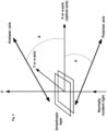
- liquid crystal molecules are frequently rod-shaped aligned, such that their long axes are on the average in the same direction making an angle ⁇ , called the tilt angle, with the normal to the transparent panels.
- the panels (1) are usually made of glass treated at their facing surfaces with transparent conducting oxide (TCO) as electrodes and a thin polymer layer to provide mono-domain alignment of the liquid crystal (LC) molecules.
- TCO transparent conducting oxide
- Some glass micro-spheres are inserted to act as spacers to determine the thickness of the device.
- liquid crystal modes which by their nature exhibite isotropic change of the refractive index such as blue phases of short pitch, and polymer dispersed liquid crystals with small LC droplets.
- Variable index modes are important to provide phase-only modulations which is of importance for spatial light modulators.
- LCD electro-optic modes which are based on the effective birefringence variation and the optic axis rotation, when an electric field is applied between the two electrodes.
- Non-limiting examples include the hybrid mode, twisted nematic mode, in-plane switching mode, pi-cell, vertically-aligned LC, smectic modes, chiral smectic mode, flexo-electric mode, smectic A, dual frequency mode, cholesteric LC with small pitch, blue phases, heliconical LC phases, distorted helix ferroelectric (DHF), and surface stabilized ferroelectric LC (SSFLC).
- the smectic and cholesteric modes exhibit other characteristics when microparticles are embedded in them.
- Another problem solved in the present invention is the strong dependence on the angle of incidence.
- the retardation vanishes and phase modulation becomes asymmetric with respect to the normal to the transparent panels.
- each light beam may experience different phase retardation.
- the devices of the embodiments are capable of extending their angular field of view. Slow switching speed attributed to the majority of the existing LCDs, particularly when thick liquid crystal layers are used, is also overcome by the devices of the present embodiments.
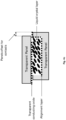
- the composite structure may be formed from liquid crystal by creating random liquid crystal micro-domains on at least one of the panels, so that there is a large index mismatch between neighbouring micro-domains at one orientational state of the liquid crystal. This mismatch actually decreases as the liquid crystal molecular orientation changes with external field tuning.
- the alignment layer deposited on the transparent panels is made of random liquid crystal micro-domains by one of the methods of nano-patterning of the transparent conductive electrode (TCE) layer or photo-alignment of the photosensitive polymer layer or thin chalcogenide glass.
- the liquid crystal micro-domains are created with refractive index mismatching between them at one state (for example, parallel n ⁇ ) and nearly full matching at the other state (for example, perpendicular n ⁇ ), which is tuned by an external field.
- the index matching or mismatching states can be reversed depending on whether the micro-domains are hydrophilic or hydrophobic and whether the liquid crystal has negative or positive dielectric anisotropy.
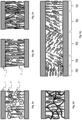
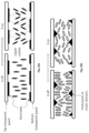
- Figs. 3a-3e illustrating the above embodiment describing the scattering medium which is achieved by having micro-domains at the panels randomly oriented.
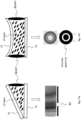
- the microparticles (2) may have a different shape, thereby resulting in different formed structures of the micro-domains.
- Fig. 3a shows random micro-fibres (2) inside the liquid crystal (3) medium.
- Fig. 3b shows random micro-posts or micro-walls (2) oriented almost perpendicular between the two transparent panels (1), and the liquid crystal molecules (3) filling the space between them and maybe even infiltrating them at least partially.
- the micro-posts (2) may have various shapes, such as helices, cones or zigzag shapes, which can reduce the angular dependence of the scattering.
- Fig. 3c shows a skeleton structure of the micro-posts filled with the liquid crystal.
- Fig. 3d shows a mesoporous matrix of random micro-fibres filled with the liquid crystal.
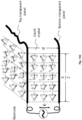
- Fig. 3e illustrates an exemplary device of the embodiments with one of the panels having different micro-domains (R1-R5) that can induce different liquid crystal molecular orientations so that the refractive index mismatch between the neighbouring domains is large at one orientational state of the liquid crystal molecules and becomes smaller at different orientational states.
- the random orientation of the micro-domains causes large scattering at zero voltage. But when the voltage increases, the index mismatch between the micro-domains starts to decrease and so does the scattering. Furthermore, the colour of the device may be tuned by selecting different sizes of the microparticles, different raw materials, different porosities or different refractive indices. As noted above, the porous silicon microparticles having different porosity and oxidation levels produce different colours of scattered light. Mesoporous silicon matrix at different oxidation levels is another possibility for a random scattering structure which becomes tunable when infiltrated with liquid crystals.
- the porous microparticles may be functionalised with an organic or inorganic molecular layer or nano-layer to control the way the liquid crystal molecules are oriented on their surface and to maximise the randomness of the micro-regions comprising the microparticles and the liquid crystal surrounding.
- the pores size of the microparticles is not limited and can range from few nm in diameter to hundreds of nm or even more. The larger the number of pores and their diameter, the better as long as they are on the micron scale because then the effective index of the infiltrated microparticle becomes closer to one of the principal refractive indices of the liquid crystal and their density becomes closer to that of the liquid crystal thus minimising sedimentation effects over time.
- Organic or non-organic tubes normally used for drug delivery can be used as the porous microparticles to produce the composite structure of the embodiments.
- organic particles are cochleates which are cigar-like microstructures consisting of a series of lipid bilayers, formed as a result of the condensation of small unilamellar negatively charged liposomes.
- cochleates which are cigar-like microstructures consisting of a series of lipid bilayers, formed as a result of the condensation of small unilamellar negatively charged liposomes.
- PS small phosphatidylserine
- Electron microscopy images usually show a typical cochleate cylinder characterised by the elongated shape and by the tight packed bilayers.
- Cochleates are usually prepared by mixing DOPS (dioleoyl phosphatidylserine) with DMPS (dimyristoyl phosphatidylserine) at the 9:1 molar ratio, and then freeze dried to get the powder form.
- DOPS dioleoyl phosphatidylserine
- DMPS diimyristoyl phosphatidylserine
- the samples are dialysed before freeze drying to remove salts.
- the obtained dry powder can be directly used for analysis or by further preparing a suspension.
- the suspension samples are dried at room temperature under vacuum.
- the suspension of the cochleate particles should be sonicated to temporarily disrupt aggregates and avoid sedimentation of the particles.
- the organic porous microstructure fiber maybe made from raw cotton, waste paper or other organic materials.
- Such structure when embedded between the two transparent panels of the embodiments and filled with the liquid crystal, forms the liquid crystal composite tunable device of the present invention.
- the micro-particles are functionalised with a nano-layer of material that can cause preferable orientation of the liquid crystal molecules in the vicinity of the micro-particles. This will result in a randomly deformed structure which reveals to higher switching contrast.
- An example of such nano-layer coating is a surfactant, but any other functionalisation material may be suitable.
- the microparticles or the mesoporous structure shown in Fig. 3d is made of thermochromic material, such as vanadium oxide, which is dielectric at room temperature, but becomes metallic above its transition temperature.
- thermochromic material such as vanadium oxide
- the device incorporating the vanadium oxide microparticles can in part strongly scatter the infrared radiation from the sun in the summer period and in part reflect or absorb it, while the transmission in the visible range can still be made high enough with proper selection of the voltage applied to the device.
- Such device may act both as a privacy window and smart window at the same time.
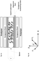
- the device may also be formed on a single layer of thermochromic material, such as vanadium oxide, a multi-layered structure or periodic structure containing vanadium oxide or any electrochromic material or phase change material, such as Ge 2 Sb 2 Te 5 (GST) (chalcogenide glass), on one side of a window, while the composite liquid crystal layer is adjacent to it.
- thermochromic material such as vanadium oxide, a multi-layered structure or periodic structure containing vanadium oxide or any electrochromic material or phase change material, such as Ge 2 Sb 2 Te 5 (GST) (chalcogenide glass)
- thermochromic material helps in reducing reflections from the smart window structure boundary, thereby improving the transmission characteristics of the window. Birefringence of liquid crystals is reduced with the incident light wavelength. Therefore, at high temperatures, it is possible to adjust the voltage in order to maintain less reflection in the visible range of the spectrum while the reflection in the infra-red remains high.
- the liquid crystal layer in the device of the embodiments has two roles: first, to provide the privacy window with its functionality, and second, to actively control the Fresnel reflection from the thermochromic material interface thus improving its contrast in the infrared range and increasing the transmission in the visible range.
- the randomly aligned micro-domains formed in the composite structure of the embodiments result in strong scattering at zero voltage.
- the liquid crystal molecules in all the micro-domains reorient themselves with the electric field direction, thereby gradually decreasing the scattering as the voltage increases.
- the device of this embodiment is used in the thermochromic smart window, first, to turn the window to become both smart and privacy window, and second, to improve the transmission characteristics of the smart window by modulation of the Fresnel reflection properties with the liquid crystal composite tunable device of the present invention.
- the index matched or mismatched states can be reversed depending on whether the walls of the embedded micro-domains are hydrophilic or hydrophobic and whether the LC has negative or positive dielectric anisotropy.
- Bistability of the devices can also be achieved depending on the choice of the liquid crystal, for example ferroelectric LC are known to exhibit bistability as well as metal-organic liquid crystalline compounds.
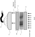
- the LCD of the embodiments may also be tuned optically by depositing a photosensitive layer, such as an intrinsic photo-conducting layer or photodiode structure, on at least one of the transparent panels. At least part of the solar spectrum impinging on the photo-sensitive layer side changes the voltage drop across the liquid crystal layer, thereby modulating the scattering.
- Some photo-conducting layers such as chalcogenide layers, can be made thin to transmit large part of the incident light. They can also act as photo-alignment layers.
- a photosensitive layer capable of absorbing the UV part of the solar spectrum and converting it into voltage drop across the device.
- such layer also provides protection from the UV radiation.
- Example of such highly efficient UV photoconductive layer is an aluminium-doped zinc-oxide nanorod array annealed in oxygen environment.
- photo-conducting polymers can be used as the photosensitive layers for visible light, while InGaAs can be used as a photoconductive layer in the short wave infrared range (SWIR).
- SWIR short wave infrared range
- a single layer is deposited on one of the transparent panels or two layers are deposited on the two panels on top of the transparent conductive electrode layer.
- Other examples of more transparent photovoltaic device include Cu based chalcogenide glasses, mixed with perovskites and using highly transparent electrodes such as metal grids.
- This optically-addressed device can be used as a smart window capable of self-controlling its transparency depending on the sunlight intensity. In the summer period, the solar intensity is strong, so this window may automatically dim and keep the house cold, while in the winter period, when there is no strong sunlight, the window may brighten, thereby keeping the house warm.
- the use of a photoconductive or photovoltaic layer in conjunction with the composite structure allows modulating the smart window's transparency by the photo-voltage or resistance change due to the incident sunlight shining on the window.
- Fig. 4a schematically showing a typical birefringent device, which in the present exemplary case is a nematic liquid crystal device having an antiparallel geometry.
- the geometry of the dielectric tensor associated with the liquid crystal molecules is shown in Fig. 4b .
- the polariser and analyser are installed to obtain intensity- or wavelength-modulation. For phase-only modulation, only polariser is installed, while for polarisation-independent operation, neither polariser, nor analyser is required.
- an improved gap uniformity can be obtained by etching one of the glass substrates with the etch depth equals to the desired cell gap.
- the panel surfaces are then coated with the necessary layers of transparent conducting oxide and alignment materials, and with optional layers, such as dielectric mirrors for a Fabry-Perot cavity tunable filter or photoconductive layers.
- the second (bottom) panel is not etched, but simply pressed and glued to the bottom of the device without spaces.
- the substrates are laterally shifted by an offset so that the connection area is exposed on both substrates from right and from left.
- etching techniques chemical, ion-beam or laser-beam
- different means for easy electrical connections are possible, for example by drilling holes in the transparent panels followed by filling them with a conducting material. This is important for pixelated devices in which the number of electrical connections increases with the number of pixels.
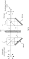
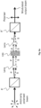
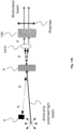
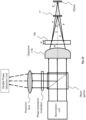
- a polarisation liquid-crystal retarder system with improved light throughput comprising the LCD of the present invention is shown in Fig. 5a . It is based on the Mach-Zehnder interferometer configuration having an arbitrarily polarised beam split with a conventional polarised beam splitter (4) into two orthogonally polarised and collimated beams P and S.
- the conventional Mach-Zehnder interferometer determines the relative phase shift variations between these two collimated beams derived by splitting light from a single source. The generated phase shifts between the two beams P and S is caused by the sample or a change in length of one of the paths.
- the P-beam passes through the liquid crystal device (100) of the embodiments oriented at 90 degrees, meaning that its optic axis is parallel to (or along) the P-polarisation direction. Hence, this beam is affected by the extraordinary refractive index that varies with the applied voltage.
- the S-beam passes through another section of the LCD (100) and is affected by the ordinary refractive index, which does not vary with the applied voltage.
- This is similar to the situation when the incident light beam is linearly polarised at 45 degrees to the optics axis.
- Figs. 5b, 5c and 5d schematically showing three uses of the output modulated beam from Fig. 5a .
- the modulated beam is passing through an optical etalon having an output transfer function of multiple narrow spectral bands, so that by modulating the LCD (100), the output spectrum includes multiple narrow spectral bands variable with the voltage.
- the modulated beam is passing through an output of an illuminator connected to an optical fibre which can be used remotely as a light source with various spectroscopic or imaging systems.
- Fig. 5b the modulated beam is passing through an optical etalon having an output transfer function of multiple narrow spectral bands, so that by modulating the LCD (100), the output spectrum includes multiple narrow spectral bands variable with the voltage.
- the modulated beam is passing through an output of an illuminator connected to an optical fibre which can be used remotely as a light source with various spectroscopic or imaging systems.
- the modulated beam being reflected or transmitted through a sample is then directed to a parallel detector or to an imaging system either for spectral measurement applications, or for hyperspectral imaging purposes, respectively.
- a half-waveplate or polarisation rotator should be inserted in the S-beam path both before and after the cell, so that the beam passing the cell becomes P-polarised, and then converted back to S to be reflected by the polarised beam splitter (4).
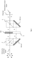
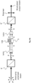
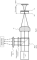
- Fig. 6 showing the similar configuration as above, but with the bottom cell (5) empty (without liquid crystal inside) or with the filled cell oriented at 0 degree.
- the S-beam is now passing through either the empty bottom cell or a filled cell oriented at 0 degree (5).
- the filled cell must be oriented at zero degree so that both the P- and S-polarisation have the same phase modulation.
- this configuration can work without the output polariser and for the phase-only polarisation-independent modulation, which is useful in tunable lensing and wavefront modulation.
- the polarisation-independent phase modulation can also be achieved in this configuration, provided that, for example, a half-waveplate or polarisation rotator is inserted in the path of the S-beam both before and after the cell, so that the light beam passing the cell (5) becomes P-polarised and converted back to S to be reflected by the polarised beam splitter (4).
- the calculated phase retardation will increase by a factor of 3-4, which allows thinning of the liquid crystal layer by the same factor. Since switching time of nematic liquid crystals is proportional to the square value of the thickness, the response time of the device may be improved by a factor of 9-16.
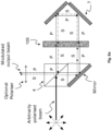
- Fig. 7 illustrating the system of the embodiments based on the Michelson interferometer that uses polarisation conversion mirrors in both arms for light throughput and speed improvement.
- the whole device maybe a single solid unit with the arms glued (using the refractive index matching glue) to the sides of the polarised beam splitter (4).
- the conventional Michelson interferometer uses a beam splitter splitting a light beam into two arms. Each of those light beams is reflected back toward a beam splitter which then combines their amplitudes using the superposition principle. The resulting interference pattern that is not directed back toward the source is typically directed to some type of photoelectric detector or camera.
- the S-polarised beam is first transmitted through either an empty cell (5) or a filled cell positioned at 0 degree, reflected from a first polarisation conversion mirror (6') converting the beam to P-polarisation, and then transmitted through a second polarisation conversion mirror (6").
- the polarised P-beam is then directed to the filled LCD (100) oriented at 90 degrees, reflected from the second polarisation conversion mirror (6"), then converted to S-polarisation and again reflected from the first polarisation conversion mirror (6') to recombine with the beam from the other interferometer channel.
- the polarisation conversion can be performed by several means, for example using a quarter waveplate (QWP) and regular mirror, a Faraday mirror, a metallic grating with the Gaussian profile of the gratings lines or other means.
- QWP quarter waveplate
- regular mirror a Faraday mirror
- metallic grating with the Gaussian profile of the gratings lines or other means.
- the cell (5) in the bottom arm can be empty to enhance the retardation modulation or filled, oriented at 0 degree to provide polarisation-independent phase modulation. In the latter case, the output polariser is not necessary.
- a Sagnac interferometer (or a ring interferometer) is based on a phenomenon of interference that is elicited by rotation.
- a beam of incident light is split and the two beams are made to follow the same path but in opposite directions.
- the two beams are allowed to exit the ring and undergo interference.
- the relative phases of the two exiting beams, and thus the position of the interference fringes are shifted according to the angular velocity of the apparatus.
- the interferometer when the interferometer is at rest with respect to the earth, the light travels at a constant speed. However, when the interferometer system is spun, one beam of light will slow with respect to the other beam of light.
- Fibre-optic and ring-laser gyroscopes are based on this phenomenon.
- Fig. 8a showing a polarisation liquid-crystal retarder system with improved light throughput based on the Sagnac interferometer configuration.
- the P and S-beams pass twice through the LCD (100) with the help of a retroreflector (7) or two mirrors.
- the configuration shown in Fig. 8b is similar to the previous configuration shown in Fig. 8a , but has an empty cell (5) (without liquid crystal).
- the empty cell (5) can be filled with the liquid crystal, but then it should be oriented at 0 degree, and no output polariser is needed.
- polarisation-independent phase-only modulation is achieved, which is important for many applications including polarisation-independent virtual reality applications and tunable focusing.
- the Sagnac interferometer configurations which are shown in Figs. 8a-8b , may be further supplemented with a polarisation conversion mirror (6) installed instead of the retroreflector (7).
- the respective Sagnac interferometer configurations are shown in Fig. 8c-8d .
- the retroreflector (7) or the polarisation conversion mirror (6) may constitute one of the transparent panels (1) of the LCD (100) of the embodiments, or attached with refractive index-matching glue to one of the external sides of the transparent panels (1).
- a Wollaston polariser consists of two birefringent right-angle triangle prisms cemented together, such that their optical axes are perpendicular. It separates randomly polarised or unpolarised light into two orthogonal linearly polarised outgoing beams. As light passes through such polariser, a symmetric deviation between the ordinary and extraordinary beams is created. The resulting beams are of orthogonal linear polarisation states and have equal intensity and a large angular deviation, which is determined by the prisms' wedge angle and the wavelength of the light.
- Commercial Wollaston polarisers are available with divergence angles from 15° to about 45°.
- a Rochon polariser is very similar to the Wollaston polariser, but the ordinary beam passes through the prism without deviation.
- the Rochon polariser also consists of two birefringent material prisms in optical contact with one another. As the ordinary beam is not deviated on both sides of the prism, the ordinary and extraordinary beams remain collinear through the first prism. Upon entering the second prism, the ordinary rays do not experience a change in the refractive index and pass through the prism without deviation, while the extraordinary rays refract at the interface.
- Fig. 9a showing a polarisation liquid-crystal retarder system of the embodiments incorporating either two Wollaston polarisers or two Rochon polarisers (8' and 8").
- these two polarisers have the property of splitting the incident beam into two orthogonally polarised beams with a small angle in between.
- the two P- and S-beams are then collimated using a lens, passes the liquid crystal device (100) of the present invention, collected again and recombined by a polariser at the output.
- Fig. 9b The similar configuration, but with the bottom cell (5) empty (without liquid crystal) or filled with the liquid crystal and positioned at 0 degree is shown in Fig. 9b .
- one beam passes through the filled LCD (100) and the other beam passes through the empty bottom cell (5) or filled and oriented at 0 degrees.
- ⁇ 2 ⁇ d ( n e -1) / ⁇ , which is larger. Therefore, the latter configuration shown in Fig. 9b with the empty bottom cell (5) is preferable.
- polarisation independent modulation is achieved and no need for the output polariser.
- the polarisation-independent phase modulation can also be achieved in all the configurations shown in Figs. 9a-9c , provided that, for example, a half-waveplate or polarisation rotator is inserted in the path of the S-beam both before and after the cell, so that the light beam passing the cell (5) becomes P-polarised and converted back to S to be recombined with the other beam in the Wollaston or Rochon polariser.
- Fig. 10 showing the Mach-Zehnder interferometer configuration with two channels. It is similar to the configuration shown in Fig. 5a except that there are two LCDs (100' and 100"), and their optic axes are aligned at 45 degrees with respect to the P or S polarisations, both at the top and at the bottom of the system. As a result, the two beams become modulated, and when passing through the output polarised beam splitter (4), two modulated channels of the same or differently modulated beams are obtained.
- This configuration has no loss in light throughput and the advantage of having two modulated beams at the same time, which can be useful for measuring two different samples simultaneously.
- the system configuration shown in Fig. 11 may be combined with coloured parallel detectors.
- coloured parallel detectors As an example, consider an output of three wavelengths centred at the standard colour camera band at 450nm, 550 and 650nm. Since the three bands are tuned, three spectral images are obtained at each voltage, and the final number of spectral images obtained is the number of the voltages multiplied by 3.
- the Fabry-Pérot resonator with the LCD of the present invention it is possible to design the Fabry-Pérot resonator with the LCD of the present invention to produce peaks centred at the major wavelengths of the coloured pixels, and by tuning them the larger number of spectral images can be obtained.
- the dielectric mirrors (6) in Fig. 11 may be made in a way that the reflection and transmission through the device exhibit interference with no need for polarisers, for example by having different reflectivity at different wavelengths.
- the tunable birefringent element (TBE) sandwiched between these two mirrors can then tune these colours by applying an external field. If the TBE layer is made thick enough, then the colours can disappear at the high retardation state, because the different interference orders become close to each other. As the retardation decreases, for example by applying voltage to the LCD (100), the interference orders become separated and colours start to appear depending on the applied voltage or temperature.
- an interference-based smart window can be built.
- the system configurations of the above embodiments, which incorporate both the LCD (100) and the empty cell (5) can be used for measurements of a refractive index or thickness of transparent materials.
- These configurations acting as orthogonal polarisation interferometers have the LCD sample arm (100) with the S-polarisation and the empty cell reference arm (5) with the P-polarised beam.
- the reference arm may contain the cell filled with liquid crystal or tunable birefringent element instead and then should be positioned at 0 degree.
- the output phase of the light traversing the sample can be measured similar to the phase-shift interferometry by providing different known phase changes to the P-polarised beam passing the tunable birefringent element.
- the output analyser is a must in this case in order to combine the two beams.
- phase change of the light traversing the sample from the output signal after the output analyser by providing at least three known different phase differences between the reference and sample arms.
- This can be used for refractive index measurement of gases and liquids flowing through the empty cell or for solid transparent materials. In the case of the solid transparent materials, it is possible to measure their thickness, assuming that the refractive index is known. Alternatively, it is also possible to extract intrinsic birefringence in the sample and calculate stresses in the sample material, for example, in glass.
- the system of the present invention can be configured to convert one of the polarisations into the other.
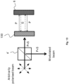
- the system shown in Fig. 12a has a spatial separation configuration, while the system shown in Fig. 12b has an angular separation configuration.
- the polarisation conversion in Fig. 12a is done with the help of the polarised beam splitters (4) and polarisation conversion mirrors (6).
- the configuration shown in Fig. 12b has a further advantage of using the flat elements, such as a wire grid polariser (9) or an achromatic quarter waveplate (not shown).
- the wire grid polariser (9) lets the P-polarisation to pass, but reflects the S polarisation. Consequently, the S-polarised beam upon reflection from the polarisation conversion mirror (6) becomes P-polarised, thus passing through the wire grid polariser (9) at different angle from the initial P-polarised beam.
- the angles of the two beams should be small in order to avoid any modulation variations over different sections of the beams.
- the liquid crystal device (100) positioned at 45 degrees, capable of minimising the angle dependence, such as pi-cell, is preferably used in this case.
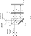
- Fig. 13 showing a polarisation liquid-crystal retarder system with a polarisation conversion mirror (6) for polarisation-independent phase-only modulation.
- the polarisation conversion mirror (6) is installed behind the LCD (100) oriented at an arbitrary angle.
- the polarisation conversion mirror (6) may comprise a quarter waveplate (QWP) combined with a mirror, or it can be made of a metallic grating with the grating lines having Gaussian profile.
- QWP quarter waveplate
- a Faraday rotator can also operate as the polarisation conversion mirror (6) in the reflection mode.
- the P polarisation is converted to S upon reflection, while S converts to P.
- the two polarisations accumulate the same phase modulation as shown in Fig. 13 .
- the retarder does not have to be oriented at a specific angle for the polarisation-independent phase-only modulation to occur.
- the assembly of an arbitrarily oriented retarder and polarisation conversion mirror acts as a polarisation-independent phase-only modulator with the phase modulation equal to 2 ⁇ av .
- the beam splitter (4') shown in Fig. 13 is optional and may be removed if the light incidence is at oblique angle.
- the Sagnac configurations shown in Figs. 8a-8d can be used in this system.
- the optic axis rotates in the plane of the transparent panels and is characterised by the angle ⁇ .
- the presented polarisation-independent phase-modulation configuration can also work with ferroelectric liquid crystals which are faster.
- the exemplary liquid crystal modes in which the optic axis remains in the plane of the LCD transparent panels are the in-plane switching mode shown in Fig. 15a and the ferroelectric mode shown in Fig. 15b .
- Another exemplary liquid crystal mode is shown in Figs. 16a-16b illustrating the LCD with compensating waveplates and other modes containing multiple domains: (a) a patterned vertically aligned mode; and (b) a multi-domain vertically aligned mode, in two voltage regimes (switched of and switched on).
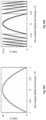
- the LCD of the present invention can be modified to exhibit coloured bands on its surface which can be tuned with the voltage.
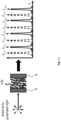
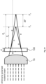
- Fig. 17a showing a wedge-type LCD of the present embodiments with partially reflecting panels (10). Each panel (10) is coated with a transparent electrode and alignment layer.
- the coloured interference bands appear on the facets of the wedge which can be selected serially using the slit aperture. These coloured bands correspond to the maxima in transmission or reflection.
- Fig. 17a showing a wedge-type LCD of the present embodiments with partially reflecting panels (10).
- Each panel (10) is coated with a transparent electrode and alignment layer.
- the wedge can be spherical, thereby producing the spectral (coloured) concentric rings appearing on the surface.
- These coloured rings can be selected using the annular aperture.
- the same effect can be obtained using a flat uniform LCD with highly resistive electrodes at high-frequency operation, so the voltage across the electrode is non-uniform and the colours will therefore appear due to the voltage distribution.
- the voltage non-uniformity in this case is a function of the frequency and electrical resistance.
- the highly resistive electrodes have conducting contacts on one side for activating the linear wedge and an annular contact around the liquid crystal active area for activating the spherical wedge.
- the beam-steering effect can be made tunable with the voltage because of the linear refractive index gradient.
- the tunable lensing effect can be created by applying symmetric voltage profile when using the annular highly conducting electrodes around the liquid crystal active area. This tunable lensing effect makes it possible to use a polarisation-independent tunable lens in the configurations of the embodiments described above for polarisation-independent phase-only modulation.
- a tunable filtering system comprising the LCD (100) of the present invention with a passive linearly-variable bandpass filter (11), which is commercially available, for example from Delta Optical Thin Film, and prepared on a transparent substrate.
- the common mode of using such filters is by mechanically moving them. However, mechanical motion is slow and might add noise to the imaging or sensing system.
- the LCD (100) is combined with the linearly-variable passive filter (11), and therefore, it is capable of selecting one or more different transmitted spectral passbands at a time.
- a lens system (12) then directs the filtered beam and couples it into an optical fibre (13), or focuses it onto an imaging or sensing system (not shown in the figure).
- the LCD of the present invention may be pixelated.
- Such pixelated LCD (100) is integrated within a polarisation-independent assembly (14) which is shown in Fig. 18 .
- the pixelated LCD (100) further comprises two polarisers (not shown here) positioned either in a parallel or crossed configuration, so that the voltage on each pixel or group of pixels facing the beam coming from one single passband is transmitted, while all other bands are blocked.
- Fig. 20 schematically shows a tunable filtering system comprising the LCD of the present invention with a dispersive element (15) having appropriate optics.
- the dispersive element (15) can be a prism or grating and can produce the array of filtered beams.
- the system of the present embodiment can operate also in a reflection mode with appropriate and commercially available mirrors, lenses and polarised beam splitters arrangements.
- the linearly-variable passive filter (11) of the previous configuration may also be replaced with a passive wedged cavity similar to that shown in Figs. 17a-17b , but without the voltage applied to the liquid crystal layer.
- the linearly-variable passive filter (11) may be replaced with an empty cavity or a cavity filled with any passive material.
- the pixelated LC device of Figs. 18 and 20 should select an annular zone which is variable with the voltage applied.
- Fig. 21 schematically showing a double-focus system comprising the LCD (100) of the present invention and a birefringent plate, a lens or a lens system (16) installed in the path of a converging beam.
- ⁇ F LC d LC tan ⁇ i tan ⁇ e ⁇ tan ⁇ o , which for small angles can be approximated as AF LC ⁇ d LC ( n e - n o ) / n e n o .
- Fig. 21 schematically showing an orthogonally-polarised beam in-line interferometer based on the system configuration shown in Fig. 21 .
- a polarisation splitting mirror (17) reflecting only the ordinary wave is introduced at the focal plane F o (ordinary), thereby producing a reference beam, while the object of interest is located at the focal plane F e (extraordinary).
- the polarisation splitting mirror (17) may be made of a planar wire grid polariser or using the multi-layered flat polarizing beam splitter available from 3M industries.
- the two orthogonally polarised beams are split into three channels, and a waveplate is inserted in each channel to produce different phase shifts.
- the two orthogonal polarisations are then recombined at an analyser plane located before each detector (camera or single detector).
- this interferometer can still operate as an in-line parallel-beam interferometer (an orthogonal-polarisation interferometer with parallel beams), and may be used for serial phase modulation.
- this interferometer in the field (where sub-nm resolution range and the axial direction matter), for example surface topography, focus tracking and vibrometry.
- FIG. 23 schematically showing an orthogonally-polarised beam in-line interferometer having the cholesteric LCD (100) of the present invention combined with a quarter waveplate (19).
- the quarter waveplate (19) is inserted near the object of interest within the focal region of a microscope objective (18) and within the temporal coherence region of the beam, so that both left and right circularly polarised beams are reflected from within the focal region of the objective (18).
- the reflected wave from the cholesteric LCD (100) is circularly polarised having the same helicity as the cholesteric LC helix, while the transmitted wave has the opposite helicity. This selective reflection phenomenon is also known as the circular Bragg reflection phenomenon.
- the two beams are brought together to interfere on a detector.
- At least three phase shifts can be introduced between the two beams serially using a modulator, or in parallel using at least three channels having different phase shifts. Since the two interfering beams are now circularly polarised, the phase shifts can be introduced by passing the two beams through the linear polarisers positioned at different orientations without the need for waveplates.
- the serial phase modulation can be achieved by rotating the linear polariser. Since the LCD (100) reflects one circular polarisation at certain range of wavelengths, the operating wavelengths can be chosen to be within the reflection band of the LCD (100).
- the double focus for two orthogonally linearly-polarised beams can also be achieved using an LC lens or a combination of the LC phase-only spatial light modulator with a standard lens.
- a parabolic radial mask is written on the spatial light modulator plane with large number of pixels.
- the ordinary wave is not affected this way. It is focused in the close proximity to the original focal plane of the lens.
- the extraordinary wave is to the contrary modulated and shifted by the amount determined by the maximum phase written on the spatial light modulator and on the numerical aperture of the lens.
- ⁇ f ⁇ max / ⁇ NA 2 .
- Polarisation-independent tunable focusing can then be obtained by cascading two devices oriented at 90 degrees to each other, or by combining the proposed device with the polarisation-independent assembly configuration described above.
- the spatial light modulator may be used to extend the depth of field of the imaging system by placing it in the exit pupil plane and writing the annular regions on it that provide equal phase shifts, but variable from one annulus to another.
- the spatial light modulator uses several parabolic profiles of the phase, each corresponding to slightly different focal point. The combination of the several focus regions provides an extended depth of field. Alternatively, one can scan the different phase shift masks fast enough, so that an average image is obtained with the extended depth of field. Minor image processing can then bring the image back to nearly the same quality as the original focused image.
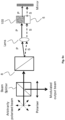
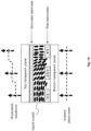
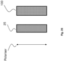
- a wide-range tunable spectral filter comprises a coupling medium (20), such as a prism, gratings, a waveguide or an optical fibre, coated with a multilayer structure comprising a thin absorbing layer (21), such as metal (for example, chromium metal of 4-8-nm thickness) in contact with said coupling medium (20), a low refractive index dielectric layer (22) (for example, magnesium fluoride having few hundreds nanometre thickness) on top of said absorbing layer (21), the liquid crystal composite tunable device (LCD) (100) of the present invention superimposed on top of said dielectric layer (22), a transparent electrode layer (23) coating the top transparent panel (1) of said LCD (100), and a semi-infinite dielectric medium layer (24) on top of said electrode layer (23).
- a coupling medium (20) such as a prism, gratings, a waveguide or an optical fibre
- a multilayer structure comprising a thin absorbing layer (21), such as metal (for example,
- the resonance maybe interpreted in several terms, such as a special type of a guided mode resonance, Fano resonance or coupled waveguides resonance. Tunability can be achieved by modulating an external magnetic field, electric field, optical field or thermal field applied to the filter. Since for this device, the modulation required is phase-only, then the LCD layer (100) maybe even replaced with other electro-optic, magneto-optic, photosensitive or thermo-optic material, which may provide easier means of preparation or operation or maybe exhibiting ultrafast tuning of the resonance wavelength.
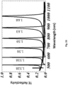
- the dielectric layer (22) thickness affects strongly the full width at half maximum, and it is possible to get extremely narrow peaks by increasing the thickness of this layer. This is not possible by either using plasmonic structures because of their high absorption, or by the standard guided mode resonant structure at a wide spectral range as demonstrated here.
- the incident light beam can be generated after polarisation splitting using one of the system configurations of the embodiments described above.
- the entire system based on this backward resonating structure further comprises polarisation conversion elements to get the two polarisation components modulated similarly by the same device.
- the tunable spectral filter of the present embodiment can be combined with the system configurations described above to achieve polarisation-independent operation
- the absorbing layer (21) and its combination with the dielectric layer (22) allows propagation of several types of surface electromagnetic waves, such as Zennick wave, Tamm wave, or surface plasmon resonance wave.
- the LCD (100) of the present invention incorporated in this tunable spectral filter is thick enough to allow guided waves.
- the interaction between the two different types of waves (surface electromagnetic waves and guided waves) causes a resonance in reflection due to constructive interference in the backward direction.
- the location of this resulting resonance is highly sensitive to the liquid crystal properties and therefore, can be used as a tunable filter or a refractive index sensor.
- the advantages of this tunable filter is in its wide range tuning, narrowband and fast response because the thickness of the LCD layer can be thinner than 1 micron for visible range operation.
- other electro-optic, magneto-optic, photosensitive or thermo-optic materials can be used instead of the LCD layer.
- Fig. 25 shows a simulated transverse electric reflectivity from the wide-range tunable spectral filter of the above embodiment shown in Fig. 24 .
- the coupling medium (20) is an SF11 glass prism
- the angle of incidence inside the prism is 52 degrees
- the stack of layers is 6-nm Cr (21) / 575-nm MgF 2 (22) / 603-nm liquid crystal (100) oriented so that the extraordinary mode is excited and the refractive index is variable as shown near each resonance peak/MgF 2 layer (22).
- the liquid crystal composite tunable device of the present invention can be used in privacy or smart windows.
- the system comprising the LCD (100) of the present invention for use in such tunable windows is illustrated in Fig. 26 and further comprises a polariser and an achromatic waveplate (25).
- the achromatic waveplate (25) is tunable and designed to manipulate the polarisation state of the incident light and its transmission through the LCD (100), which is in turn controlled via the tunable achromatic waveplate (25).
- Helical anisotropic LCDs such as chiral smectic LCDs, cholesteric LCDs, heliconical LCDs, or helical photonic crystals prepared by the oblique angle deposition technique, are examples of the LCDs of the present invention used in the privacy or smart windows of the embodiments.
- These helical structures reflect only one circular polarisation which has the same helicity of the helical structure. The circular polarisation having the opposite helicity is transmitted through.
- the polariser shown in Fig. 26 is preferably reflective, such as a metallic wire-grid polariser reflecting one component of the unpolarised solar spectrum, while the other component is transmitted. Nearly 50% reflection from the polariser surface prevents seeing clearly from one side of the privacy window, whereas the other side of the window is completely transparent for seeing due to the light part that transmitted through.
- the linear polarisation is transmitted through the tunable achromatic waveplate (25) which can be at several switching states:
- Figs. 27a-27b shows a prototype privacy window of the present invention with no voltage applied on the left and with applied voltage on the right.
- Fig. 27a shows this privacy window based on the LCD (100) of the present invention comprising the porous microparticles made of porous silica of about 2-3 ⁇ m in size and 4% concentration.
- the liquid crystal used in this example is Nematic BL036 purchased from Merck, and the gap thickness was 12 ⁇ m.
- Fig. 27b further shows this window based on the LCD of the present invention comprising non-porous silica microspheres of 2.54 ⁇ m and 4% concentration.
- the liquid crystal used in this example was also Nematic BL036 purchased from Merck, and the gap thickness was 12 ⁇ m.
- the tunable window described herein may also be used to transmit 50% of the visible light of the solar spectrum at all times while controlling the transmission of the infrared light. This can be accomplished by choosing the pitch of the helix to be in the microns range and the achromatic waveplate to operate in the infrared range. This way the window acts as a smart window to keep the house cool during the summer period and warm during the winter period.
- two LCDs of the present invention having their optic axis preferably oriented at 90 degrees with respect to each other, may be combined in one system.
- the incident polarisation is at 45 degrees with respect to the optic axis of the first LCD in the system.
- Such system when driven at different voltages applied to the two different LCDs, provides excellent tunability between an achromatic half wave, a quarter waveplate and a full waveplate.
- an achromatic tunable lens comprises the LCD of the present invention.
- an imaging system comprises an achromatic tunable lens, which is a refractive lens, and a diffractive lens, for example the Fresnel-type lens having a negative dispersion.
- the focal length of this diffractive lens is dependent on the wavelength of the incident light, so that the longer the wavelength is, the shorter the focal length is, which is opposite to the focal length dispersion of a refractive lens.
- Fig. 28a shows a parabolic profile of the optical path difference (wavelength) of a refractive lens with the M maximum. Since the dispersion of glasses and LC materials is such that the refractive index decreases as the wavelength increases, it is evident from the above equation of the focal length f that the focal length increases as the wavelength increases. In other words, the blue colour is focused first, then the green colour and then the red colour. This phenomenon is usually observed with the human eye, which is a typical refractive lens.
- Fig. 28b showing the corresponding segmented profile of the refractive index represented in a wrapped way of a diffractive Fresnel lens.
- the lens radius is divided into five regions and the phase is wrapped five times so that the maximum optical path difference at each zone is M/5 waves.
- the zones become denser as the distance from the centre increases.
- the radius of zone j is given by r j ⁇ j ⁇ 0 f , where ⁇ 0 , is the design wavelength. Because of this specific design for the specific wavelength, the focal length varies with the wavelength in an opposite way to the refractive lens.
- the red colour is now focused first, then the green and then the blue, opposite to the dispersion of the refractive lens.
- the focal length at the design wavelength has the dispersion due to the refractive index dispersion according to the above equation of the focal length f .
- the diffractive lens zones are made from a material having the standard refractive index dispersion (index decreases with the wavelength), some compensation may occur, and the final focal length of the Fresnel lens might not have significant dispersion.
- this is not enough in many cases where the achromatic operation is required, for example in imaging systems.
- n g ⁇ A 1 + B 1 ⁇ 2 + C 1 ⁇ 4 , where A 1 , B 1 and C 1 are constants, the dispersion of the focal length of the diffractive lens behaves approximately as follows: f ⁇ ⁇ ⁇ 0 2 d R 2 ⁇ A 2 + B 2 ⁇ + C 2 ⁇ 3 , where A 2 , B 2 and C 2 are the Cauchy coefficients for the dispersion function of the refractive index of the Fresnel lens material.
- the refractive and diffractive lenses in their achromatic combination should be of the same power to minimise the requirement on the refractive index dispersion relation. It is also possible to choose them both to be made of the liquid crystal composite of the present invention and tune them so that at each external field the focal length obtained is wavelength-independent in a wide spectral range.
- the diffractive element zones maybe optimised both in their width and in their optical path difference so that each zone is capable of minimising the chromatic aberration. Assuming the zones corresponding to one designed wavelength are r j 2 ⁇ j ⁇ 1 f 2 , then it is possible to introduce other zones between them that would correspond to a different design wavelength r j 2 ⁇ j ⁇ 2 f 2 . As a result, the obtained generalised Fresnel lens is suitable for wide range of wavelengths. In a particular embodiment of a manufacturing method shown in Fig. 29 and described below, these zones are created as annulus on the transparent electrodes having widths much less than the designed width of the Fresnel zone defined by r j+ 1 - r j .
- Fresnel zone structure provides a further degree of freedom to adjust the phase profile, so as to minimise chromatic aberrations, extend the depth of field and avoid the polarisation dependence.
- Another advantage of having the fine structure of each Fresnel zone to be created of many annuli is a possibility to create different phase profiles interlaced with each other.
- Each profile can be designed to be appropriate for a specific wavelengths region or specific focus region, so that the extended depth of field and achromatic operations are obtained.
- phase profiles can be found using large variety of optimisation algorithms known in the art such as neural nets, simulated annealing and machine learning.
- part of the sub-Fresnel zones are nano-patterned with lines in one direction, but other sub-Fresnel zones are patterned with lines in the perpendicular direction. This is important because the LC molecules orientation follows the nano-grid pattern direction, and therefore, some regions of the Fresnel lens provide focusing for one polarisation (for instance, transverse-electric), and other regions with the perpendicular orientation provide tunable focusing of the orthogonal polarisation (such as transverse-magnetic).
- the manufacturing method comprises the following steps:
- the annular regions and sub-regions are replaced with rectangular lines or sub-lines so that the tunable achromatic lens becomes a tunable achromatic cylindrical lens.
Landscapes
- Physics & Mathematics (AREA)
- Nonlinear Science (AREA)
- Chemical & Material Sciences (AREA)
- General Physics & Mathematics (AREA)
- Optics & Photonics (AREA)
- Crystallography & Structural Chemistry (AREA)
- Mathematical Physics (AREA)
- Engineering & Computer Science (AREA)
- Structural Engineering (AREA)
- Civil Engineering (AREA)
- Spectroscopy & Molecular Physics (AREA)
- Architecture (AREA)
- Organic Chemistry (AREA)
- Materials Engineering (AREA)
- Liquid Crystal (AREA)
Claims (15)
- Abstimmbare Flüssigkristallverbundvorrichtung (100) zur schnellen polarisationsunabhängigen Modulation eines einfallenden Lichtbündels, umfassend:(a) zwei Stütz- und Funktionsscheiben (1), die aus transparentem Material hergestellt sind, wie etwa Glas oder transparentem flexiblem Material, wobei mindestens eine von ihnen mit einem transparenten leitenden Oxid beschichtet ist, das eine transparente leitfähige Elektrodenschicht bildet, die in Pixel gemustert ist, und mit optional mindestens einer zusätzlichen Schicht, die aus einer Ausrichtungsschicht, Antireflexbeschichtungsschicht, thermochromen oder elektrochromen Schicht, photoleitfähigen oder photoempfindlichen Schicht ausgewählt ist;wobei die abstimmbare Flüssigkristallverbundvorrichtung (100) dadurch gekennzeichnet ist, dass sie Folgendes umfasst:(b) eine Verbundstruktur, die zwischen den zwei Scheiben eingelegt ist und aus einem Flüssigkristall (3) und porösen Mikropartikeln (2), die durch den Flüssigkristall umgeben und mit dem Flüssigkristall infiltriert sind, hergestellt ist;wobei(i) die porösen Mikropartikel einen durchschnittlichen Brechungsindex aufweisen, der ungefähr gleich einem der Hauptbrechungsindizes von Flüssigkristallen ist, und räumliche Abmessungen im Bereich von etwa 0,3-30 Mikron aufweisen;(ii) ein effektiver Brechungsindex der porösen Mikropartikel mit dem des Flüssigkristalls in einem Orientierungszustand (zum Beispiel parallel n∥) des Flüssigkristalls übereinstimmt und in einem anderen Orientierungszustand (zum Beispiel senkrecht n⊥) des Flüssigkristalls über eine große Fehlanpassung verfügt;(iii) eine Brechungsindexfehlanpassung zwischen den Mikropartikeln und dem Flüssigkristall durch Anlegen eines externen elektrischen oder magnetischen Felds thermisch oder optisch abgestimmt wird, wobei die transparente leitfähige Elektrodenschicht in Pixel gemustert ist und wobei das externe Feld an jedes Pixel einzeln oder an eine Gruppe der Pixel angelegt wird, wodurch sich ergibt, dass die Vorrichtung verpixelt wird, wobei jedes Pixel so eingestellt wird, dass es die Polarisation, Intensität oder Phase eines optischen Bündels modifiziert, wodurch die Vorrichtung zu einem räumlichen oder Polarisationslichtmodulator wird, um die Bildqualität zu verbessern und polarimetrische oder ellipsometrische Bilder zu erzeugen; und(iv) die Konzentration der Mikropartikel in dem Verbundstoff im Bereich von 0,1 %-50 % liegt, um einen optimalen Kontrast der Vorrichtung beim Umschalten derselben zwischen unterschiedlichen Orientierungszuständen des Flüssigkristalls bereitzustellen, wenn die Vorrichtung als Streuvorrichtung verwendet wird, und unter 0,1 % liegt, um eine signifikante Lichtstreuung zu vermeiden, wenn die Vorrichtung als Spektrum-, Phasen- oder Polarisationsmodulator verwendet wird.
- Vorrichtung nach Anspruch 1, wobei die Mikropartikel aus photoempfindlichem, thermochromem oder elektrochromem Material hergestellt sind, wobei die Mikropartikel in der Lage sind, die Infrarotstrahlung von der Sonne stark zu streuen und sie teilweise zu reflektieren oder zu absorbieren, während sie das Licht im sichtbaren Bereich durchlassen, wodurch das Fenster gleichzeitig zu einem thermochromen intelligenten Fenster und Sichtschutzfenster wird.
- Vorrichtung nach Anspruch 1, wobei mindestens eine der Scheiben ferner mit einer dünnen Polymerschicht beschichtet ist, um die Ausrichtungsschicht über der transparenten leitfähigen Elektrodenschicht zu bilden, um eine Monodomänenausrichtung der Flüssigkristallmoleküle bereitzustellen.
- Vorrichtung nach Anspruch 3, wobei die Ausrichtungsschicht aus zufälligen Flüssigkristall-Mikrodomänen durch Nanomusterung der transparenten leitfähigen Elektrodenschicht oder durch Photoausrichtung der photoempfindlichen Polymerschicht hergestellt ist.
- Vorrichtung nach Anspruch 4, wobei die benachbarten zufälligen Flüssigkristall-Mikrodomänen in einem Orientierungszustand des Flüssigkristalls eine große Brechungsindexfehlanpassung untereinander und in einem anderen Orientierungszustand nahezu vollständige Anpassung aufweisen.
- Vorrichtung nach Anspruch 5, wobei die Brechungsindexfehlanpassung durch Modulieren der Stärke, der Frequenz oder des Tastverhältnisses des externen Felds abgestimmt wird.
- Vorrichtung nach Anspruch 1, wobei die photoempfindliche Schicht eine intrinsische photoleitende Schicht oder eine Photodiodenschicht ist und die Brechungsindexfehlanpassung zwischen den Mikropartikeln und dem Flüssigkristall optisch abstimmbar ist.
- Intelligentes Fenster oder Sichtschutzfenster, umfassend die Vorrichtung nach Anspruch 1.
- Intelligentes Fenster oder Sichtschutzfenster, umfassend die Vorrichtung nach Anspruch 7, wobei das Fenster dazu ausgestaltet ist, seine Transparenz in Abhängigkeit von der Intensität des einfallenden Lichts selbst zu steuern.
- Intelligentes Fenster oder Sichtschutzfenster nach Anspruch 8, ferner umfassend eine achromatische Wellenplatte und einen Polarisator, wobei die Wellenplatte abstimmbar ist und dazu ausgestaltet ist, den Polarisationszustand des einfallenden Lichts und seine Durchlässigkeit durch die Vorrichtung zu manipulieren, wobei die Vorrichtung wiederum über die abstimmbare achromatische Wellenplatte gesteuert wird.
- Intelligentes Fenster oder Sichtschutzfenster nach Anspruch 10, wobei der Polarisator reflektierend ist oder der Polarisator ein metallischer Drahtgitterpolarisator ist, der dazu konfiguriert ist, eine Polarisationskomponente von unpolarisiertem Licht zu reflektieren und seine andere Polarisationskomponente durchzulassen.
- Intelligentes Fenster oder Sichtschutzfenster nach Anspruch 8, wobei der Flüssigkristall in der Vorrichtung eine helikale anisotrope oder helikale photonische Struktur ist, die durch die Technik der Schrägwinkelabscheidung gefertigt ist, wobei der Flüssigkristall in der Lage ist, nur zirkulare Polarisation mit der gleichen Helizität wie die helikale Struktur zu reflektieren und die zirkulare Polarisation mit der entgegengesetzten Helizität durchzulassen.
- Intelligentes Fenster oder Sichtschutzfenster nach Anspruch 10, wobei der Flüssigkristall in der Vorrichtung eine helikale anisotrope oder helikale photonische Struktur ist, die durch die Technik der Schrägwinkelabscheidung gefertigt ist, wobei der Flüssigkristall in der Lage ist, nur zirkulare Polarisation mit der gleichen Helizität wie die helikale Struktur zu reflektieren und die zirkulare Polarisation mit der entgegengesetzten Helizität durchzulassen.
- Intelligentes Fenster oder Sichtschutzfenster nach Anspruch 13, wobei die abstimmbare achromatische Wellenplatte dazu konfiguriert ist, entweder eingeschaltet zu sein, wodurch sie als achromatische Viertelwellenplatte wirkt und somit das durch sie hindurchtretende Licht in zirkular polarisiert mit der entgegengesetzten Helizität wie die Helix der helikalen Struktur umwandelt, oder ausgeschaltet zu sein, wodurch sie als Viertelwellenplatte mit einer Phasenverzögerungsverschiebung von 180 Grad gegenüber dem vorherigen Zustand wirkt und somit das durch sie hindurchtretende Licht in zirkular polarisiert mit der gleichen Helizität wie die Helix der helikalen Struktur umwandelt, oder in einen Zwischenzustand geschaltet zu sein, wodurch sie elliptisch polarisiertes Licht bereitstellt und somit das durch das Fenster hindurchtretende Licht allmählich steuert.
- Intelligentes Fenster oder Sichtschutzfenster nach Anspruch 13, wobei die Steigung und Doppelbrechung der helikalen Struktur so ausgewählt sind, dass sie über das Phänomen der zirkularen Bragg-Reflexion im Infrarotbereich verfügen, und die achromatische Wellenplatte dazu ausgestaltet ist, in demselben Bereich betrieben zu werden.
Applications Claiming Priority (3)
| Application Number | Priority Date | Filing Date | Title |
|---|---|---|---|
| US201762553954P | 2017-09-04 | 2017-09-04 | |
| US201862623566P | 2018-01-30 | 2018-01-30 | |
| PCT/IL2018/050756 WO2019043682A1 (en) | 2017-09-04 | 2018-07-11 | SPECIFIC AND PHASE MODULATING TUNABLE BIREFRINGENCE DEVICES |
Publications (2)
| Publication Number | Publication Date |
|---|---|
| EP3679110A1 EP3679110A1 (de) | 2020-07-15 |
| EP3679110B1 true EP3679110B1 (de) | 2025-03-19 |
Family
ID=63254758
Family Applications (1)
| Application Number | Title | Priority Date | Filing Date |
|---|---|---|---|
| EP18756302.8A Active EP3679110B1 (de) | 2017-09-04 | 2018-07-11 | Spektral- und phasenmodulierte abstimmbare doppelbrechungsvorrichtungen |
Country Status (4)
| Country | Link |
|---|---|
| US (2) | US11112671B2 (de) |
| EP (1) | EP3679110B1 (de) |
| IL (1) | IL273042A (de) |
| WO (1) | WO2019043682A1 (de) |
Families Citing this family (13)
| Publication number | Priority date | Publication date | Assignee | Title |
|---|---|---|---|---|
| WO2020005965A1 (en) * | 2018-06-25 | 2020-01-02 | The Regents Of The University Of California | Optically-transparent, thermally-insulating nanoporous coatings and monoliths |
| CN109188700B (zh) * | 2018-10-30 | 2021-05-11 | 京东方科技集团股份有限公司 | 光学显示系统及ar/vr显示装置 |
| CN111221197B (zh) * | 2019-11-05 | 2022-12-27 | 武汉邮电科学研究院有限公司 | 一种超表面硅基液晶复合空间光调制器 |
| US11733598B2 (en) * | 2019-12-04 | 2023-08-22 | Liqxtal Technology Inc. | Tunable light projector |
| CN113514998B (zh) * | 2020-04-10 | 2022-07-05 | 中国科学院苏州纳米技术与纳米仿生研究所 | 柔性可调谐聚焦透镜及其制备方法 |
| CN114966970B (zh) * | 2021-02-22 | 2024-04-12 | 中国计量大学 | 基于锗锑碲纳米柱阵列动态可调的透射型波片及其制备方法 |
| JP2022163925A (ja) * | 2021-04-15 | 2022-10-27 | 浜松ホトニクス株式会社 | 光補正係数予測方法、光補正係数予測装置、機械学習方法、機械学習の前処理方法、及び学習済みの学習モデル |
| JP2022163926A (ja) * | 2021-04-15 | 2022-10-27 | 浜松ホトニクス株式会社 | 光補正係数予測方法、光補正係数予測装置、機械学習方法、機械学習の前処理方法、及び学習済みの学習モデル |
| US11422429B1 (en) * | 2021-04-21 | 2022-08-23 | Ii-Vi Delaware, Inc. | Tunable optical wedge for beam steering |
| US12422621B2 (en) | 2021-10-07 | 2025-09-23 | Purdue Research Foundation | Spectral compression system and methods of using same |
| WO2024103282A1 (zh) * | 2022-11-16 | 2024-05-23 | 京东方科技集团股份有限公司 | 显示模组及其制备方法和显示装置 |
| CN115857214B (zh) * | 2022-12-06 | 2024-10-11 | 青岛智海牧洋科技有限公司 | 一种液晶偏振膜及其制备方法 |
| WO2025026549A1 (en) * | 2023-08-02 | 2025-02-06 | Huawei Technologies Co., Ltd. | A polarization-independent phase modulator |
Family Cites Families (5)
| Publication number | Priority date | Publication date | Assignee | Title |
|---|---|---|---|---|
| JPH0713137A (ja) * | 1993-06-29 | 1995-01-17 | Suzuki Yushi Kogyo Kk | 液晶内包無機中空微粒子とそれを用いた液晶表示装置 |
| US5760860A (en) * | 1994-02-25 | 1998-06-02 | The Secretary Of State For Defense In Her Britannic Majesty's Government Of The United Kingdom Of Great Britain And Northern Ireland | Electro-optic scattering type devices with color polariser for switchable color |
| KR20070107439A (ko) * | 2006-05-03 | 2007-11-07 | 삼성전자주식회사 | 액정 재료, 그의 제조방법 및 이를 이용한 액정 소자 |
| WO2016046815A1 (en) * | 2014-09-22 | 2016-03-31 | Yissum Research Development Company Of The Hebrew University Of Jerusalem Ltd. | Lc-based optical display system |
| KR101526823B1 (ko) * | 2014-12-03 | 2015-06-05 | 현대자동차주식회사 | 에어로겔을 이용한 스마트 윈도우 |
-
2018
- 2018-07-11 EP EP18756302.8A patent/EP3679110B1/de active Active
- 2018-07-11 US US16/644,637 patent/US11112671B2/en active Active
- 2018-07-11 WO PCT/IL2018/050756 patent/WO2019043682A1/en not_active Ceased
-
2020
- 2020-03-03 IL IL273042A patent/IL273042A/en unknown
-
2021
- 2021-04-19 US US17/234,341 patent/US11567381B2/en active Active
Also Published As
| Publication number | Publication date |
|---|---|
| US20210240019A1 (en) | 2021-08-05 |
| US11112671B2 (en) | 2021-09-07 |
| US11567381B2 (en) | 2023-01-31 |
| IL273042A (en) | 2020-04-30 |
| US20210072570A1 (en) | 2021-03-11 |
| WO2019043682A1 (en) | 2019-03-07 |
| EP3679110A1 (de) | 2020-07-15 |
Similar Documents
| Publication | Publication Date | Title |
|---|---|---|
| US11567381B2 (en) | Spectral and phase modulation tunable birefringence devices | |
| US11774824B2 (en) | Spectral and phase modulation tunable birefringence devices | |
| Tabiryan et al. | Advances in transparent planar optics: enabling large aperture, ultrathin lenses | |
| Kobashi et al. | Planar optics with patterned chiral liquid crystals | |
| Li et al. | Polymer‐stabilized blue phase liquid crystals for photonic applications | |
| Wen et al. | Metasurface for characterization of the polarization state of light | |
| Rafayelyan et al. | Ultrabroadband gradient-pitch Bragg-Berry mirrors | |
| US9298050B2 (en) | Terahertz in-plane and terahertz out-of-plane switching liquid crystal devices | |
| Sang et al. | Bandwidth tunable guided-mode resonance filter using contact coupled gratings at oblique incidence | |
| Isaacs et al. | Investigation of liquid crystal Fabry–Perot tunable filters: design, fabrication, and polarization independence | |
| US12140846B2 (en) | Spectral and phase modulation tunable birefringence devices | |
| Yang et al. | Dynamic optical spin Hall effect in chitosan-coated all-dielectric metamaterials for a biosensing platform | |
| Ren et al. | Active optical switches based on polarization-tuned guided-mode resonance filters for optical communication | |
| Abu Aisheh et al. | Fast tunable metamaterial liquid crystal achromatic waveplate | |
| US10146094B2 (en) | Tunable achromatic waveplates | |
| Zografopoulos et al. | Design of switchable guided-mode resonant filters in zenithal-bistable liquid-crystal gratings | |
| Sasaki et al. | Liquid crystal cells with subwavelength metallic gratings for transmissive terahertz elements with electrical tunability | |
| Zhang et al. | MWIR/LWIR filter based on Liquid–Crystal Fabry–Perot structure for tunable spectral imaging detection | |
| Petriashvili et al. | Crystal Smectic G Phase Retarder for the Real-Time Spatial-Temporal Modulation of Optical Information | |
| Aharon et al. | Liquid crystal wavelength-independent continuous polarization rotator | |
| Buzin et al. | Hybrid Tamm and quasi-BIC microcavity modes | |
| Gunyakov et al. | Polarization exchange of optical eigenmode pair in twisted-nematic Fabry-Pérot resonator | |
| Kanseri | Tunability in the polarization of light using nematic liquid crystal | |
| Nasir et al. | Electro-tunable optical cavity filters in near-infrared regime | |
| Tabiryan et al. | Fabricating vector vortex waveplates for coronagraphy |
Legal Events
| Date | Code | Title | Description |
|---|---|---|---|
| STAA | Information on the status of an ep patent application or granted ep patent |
Free format text: STATUS: UNKNOWN |
|
| STAA | Information on the status of an ep patent application or granted ep patent |
Free format text: STATUS: THE INTERNATIONAL PUBLICATION HAS BEEN MADE |
|
| PUAI | Public reference made under article 153(3) epc to a published international application that has entered the european phase |
Free format text: ORIGINAL CODE: 0009012 |
|
| STAA | Information on the status of an ep patent application or granted ep patent |
Free format text: STATUS: REQUEST FOR EXAMINATION WAS MADE |
|
| 17P | Request for examination filed |
Effective date: 20200316 |
|
| AK | Designated contracting states |
Kind code of ref document: A1 Designated state(s): AL AT BE BG CH CY CZ DE DK EE ES FI FR GB GR HR HU IE IS IT LI LT LU LV MC MK MT NL NO PL PT RO RS SE SI SK SM TR |
|
| AX | Request for extension of the european patent |
Extension state: BA ME |
|
| DAV | Request for validation of the european patent (deleted) | ||
| DAX | Request for extension of the european patent (deleted) | ||
| STAA | Information on the status of an ep patent application or granted ep patent |
Free format text: STATUS: EXAMINATION IS IN PROGRESS |
|
| 17Q | First examination report despatched |
Effective date: 20220422 |
|
| GRAP | Despatch of communication of intention to grant a patent |
Free format text: ORIGINAL CODE: EPIDOSNIGR1 |
|
| STAA | Information on the status of an ep patent application or granted ep patent |
Free format text: STATUS: GRANT OF PATENT IS INTENDED |
|
| INTG | Intention to grant announced |
Effective date: 20241022 |
|
| GRAS | Grant fee paid |
Free format text: ORIGINAL CODE: EPIDOSNIGR3 |
|
| GRAA | (expected) grant |
Free format text: ORIGINAL CODE: 0009210 |
|
| STAA | Information on the status of an ep patent application or granted ep patent |
Free format text: STATUS: THE PATENT HAS BEEN GRANTED |
|
| AK | Designated contracting states |
Kind code of ref document: B1 Designated state(s): AL AT BE BG CH CY CZ DE DK EE ES FI FR GB GR HR HU IE IS IT LI LT LU LV MC MK MT NL NO PL PT RO RS SE SI SK SM TR |
|
| REG | Reference to a national code |
Ref country code: GB Ref legal event code: FG4D |
|
| REG | Reference to a national code |
Ref country code: CH Ref legal event code: EP |
|
| REG | Reference to a national code |
Ref country code: DE Ref legal event code: R096 Ref document number: 602018080271 Country of ref document: DE |
|
| REG | Reference to a national code |
Ref country code: IE Ref legal event code: FG4D |
|
| PG25 | Lapsed in a contracting state [announced via postgrant information from national office to epo] |
Ref country code: RS Free format text: LAPSE BECAUSE OF FAILURE TO SUBMIT A TRANSLATION OF THE DESCRIPTION OR TO PAY THE FEE WITHIN THE PRESCRIBED TIME-LIMIT Effective date: 20250619 |
|
| PG25 | Lapsed in a contracting state [announced via postgrant information from national office to epo] |
Ref country code: FI Free format text: LAPSE BECAUSE OF FAILURE TO SUBMIT A TRANSLATION OF THE DESCRIPTION OR TO PAY THE FEE WITHIN THE PRESCRIBED TIME-LIMIT Effective date: 20250319 |
|
| REG | Reference to a national code |
Ref country code: LT Ref legal event code: MG9D |
|
| PG25 | Lapsed in a contracting state [announced via postgrant information from national office to epo] |
Ref country code: NO Free format text: LAPSE BECAUSE OF FAILURE TO SUBMIT A TRANSLATION OF THE DESCRIPTION OR TO PAY THE FEE WITHIN THE PRESCRIBED TIME-LIMIT Effective date: 20250619 |
|
| PG25 | Lapsed in a contracting state [announced via postgrant information from national office to epo] |
Ref country code: HR Free format text: LAPSE BECAUSE OF FAILURE TO SUBMIT A TRANSLATION OF THE DESCRIPTION OR TO PAY THE FEE WITHIN THE PRESCRIBED TIME-LIMIT Effective date: 20250319 |
|
| PG25 | Lapsed in a contracting state [announced via postgrant information from national office to epo] |
Ref country code: LV Free format text: LAPSE BECAUSE OF FAILURE TO SUBMIT A TRANSLATION OF THE DESCRIPTION OR TO PAY THE FEE WITHIN THE PRESCRIBED TIME-LIMIT Effective date: 20250319 |
|
| PG25 | Lapsed in a contracting state [announced via postgrant information from national office to epo] |
Ref country code: GR Free format text: LAPSE BECAUSE OF FAILURE TO SUBMIT A TRANSLATION OF THE DESCRIPTION OR TO PAY THE FEE WITHIN THE PRESCRIBED TIME-LIMIT Effective date: 20250620 Ref country code: BG Free format text: LAPSE BECAUSE OF FAILURE TO SUBMIT A TRANSLATION OF THE DESCRIPTION OR TO PAY THE FEE WITHIN THE PRESCRIBED TIME-LIMIT Effective date: 20250319 |
|
| REG | Reference to a national code |
Ref country code: NL Ref legal event code: MP Effective date: 20250319 |
|
| REG | Reference to a national code |
Ref country code: AT Ref legal event code: MK05 Ref document number: 1776969 Country of ref document: AT Kind code of ref document: T Effective date: 20250319 |
|
| PG25 | Lapsed in a contracting state [announced via postgrant information from national office to epo] |
Ref country code: NL Free format text: LAPSE BECAUSE OF FAILURE TO SUBMIT A TRANSLATION OF THE DESCRIPTION OR TO PAY THE FEE WITHIN THE PRESCRIBED TIME-LIMIT Effective date: 20250319 |
|
| PG25 | Lapsed in a contracting state [announced via postgrant information from national office to epo] |
Ref country code: SE Free format text: LAPSE BECAUSE OF FAILURE TO SUBMIT A TRANSLATION OF THE DESCRIPTION OR TO PAY THE FEE WITHIN THE PRESCRIBED TIME-LIMIT Effective date: 20250319 |
|
| PG25 | Lapsed in a contracting state [announced via postgrant information from national office to epo] |
Ref country code: SM Free format text: LAPSE BECAUSE OF FAILURE TO SUBMIT A TRANSLATION OF THE DESCRIPTION OR TO PAY THE FEE WITHIN THE PRESCRIBED TIME-LIMIT Effective date: 20250319 |
|
| PG25 | Lapsed in a contracting state [announced via postgrant information from national office to epo] |
Ref country code: ES Free format text: LAPSE BECAUSE OF FAILURE TO SUBMIT A TRANSLATION OF THE DESCRIPTION OR TO PAY THE FEE WITHIN THE PRESCRIBED TIME-LIMIT Effective date: 20250319 Ref country code: PT Free format text: LAPSE BECAUSE OF FAILURE TO SUBMIT A TRANSLATION OF THE DESCRIPTION OR TO PAY THE FEE WITHIN THE PRESCRIBED TIME-LIMIT Effective date: 20250721 |
|
| PGFP | Annual fee paid to national office [announced via postgrant information from national office to epo] |
Ref country code: DE Payment date: 20250722 Year of fee payment: 8 |
|
| PG25 | Lapsed in a contracting state [announced via postgrant information from national office to epo] |
Ref country code: IT Free format text: LAPSE BECAUSE OF FAILURE TO SUBMIT A TRANSLATION OF THE DESCRIPTION OR TO PAY THE FEE WITHIN THE PRESCRIBED TIME-LIMIT Effective date: 20250319 Ref country code: PL Free format text: LAPSE BECAUSE OF FAILURE TO SUBMIT A TRANSLATION OF THE DESCRIPTION OR TO PAY THE FEE WITHIN THE PRESCRIBED TIME-LIMIT Effective date: 20250319 |
|
| PGFP | Annual fee paid to national office [announced via postgrant information from national office to epo] |
Ref country code: GB Payment date: 20250722 Year of fee payment: 8 |
|
| PG25 | Lapsed in a contracting state [announced via postgrant information from national office to epo] |
Ref country code: AT Free format text: LAPSE BECAUSE OF FAILURE TO SUBMIT A TRANSLATION OF THE DESCRIPTION OR TO PAY THE FEE WITHIN THE PRESCRIBED TIME-LIMIT Effective date: 20250319 |
|
| PG25 | Lapsed in a contracting state [announced via postgrant information from national office to epo] |
Ref country code: EE Free format text: LAPSE BECAUSE OF FAILURE TO SUBMIT A TRANSLATION OF THE DESCRIPTION OR TO PAY THE FEE WITHIN THE PRESCRIBED TIME-LIMIT Effective date: 20250319 Ref country code: CZ Free format text: LAPSE BECAUSE OF FAILURE TO SUBMIT A TRANSLATION OF THE DESCRIPTION OR TO PAY THE FEE WITHIN THE PRESCRIBED TIME-LIMIT Effective date: 20250319 |
|
| PG25 | Lapsed in a contracting state [announced via postgrant information from national office to epo] |
Ref country code: RO Free format text: LAPSE BECAUSE OF FAILURE TO SUBMIT A TRANSLATION OF THE DESCRIPTION OR TO PAY THE FEE WITHIN THE PRESCRIBED TIME-LIMIT Effective date: 20250319 |
|
| PG25 | Lapsed in a contracting state [announced via postgrant information from national office to epo] |
Ref country code: SK Free format text: LAPSE BECAUSE OF FAILURE TO SUBMIT A TRANSLATION OF THE DESCRIPTION OR TO PAY THE FEE WITHIN THE PRESCRIBED TIME-LIMIT Effective date: 20250319 |
|
| PG25 | Lapsed in a contracting state [announced via postgrant information from national office to epo] |
Ref country code: IS Free format text: LAPSE BECAUSE OF FAILURE TO SUBMIT A TRANSLATION OF THE DESCRIPTION OR TO PAY THE FEE WITHIN THE PRESCRIBED TIME-LIMIT Effective date: 20250719 |
|
| REG | Reference to a national code |
Ref country code: DE Ref legal event code: R097 Ref document number: 602018080271 Country of ref document: DE |
|
| PG25 | Lapsed in a contracting state [announced via postgrant information from national office to epo] |
Ref country code: DK Free format text: LAPSE BECAUSE OF FAILURE TO SUBMIT A TRANSLATION OF THE DESCRIPTION OR TO PAY THE FEE WITHIN THE PRESCRIBED TIME-LIMIT Effective date: 20250319 |
|
| PLBE | No opposition filed within time limit |
Free format text: ORIGINAL CODE: 0009261 |
|
| STAA | Information on the status of an ep patent application or granted ep patent |
Free format text: STATUS: NO OPPOSITION FILED WITHIN TIME LIMIT |
|
| REG | Reference to a national code |
Ref country code: CH Ref legal event code: L10 Free format text: ST27 STATUS EVENT CODE: U-0-0-L10-L00 (AS PROVIDED BY THE NATIONAL OFFICE) Effective date: 20260128 |
|
| REG | Reference to a national code |
Ref country code: CH Ref legal event code: H13 Free format text: ST27 STATUS EVENT CODE: U-0-0-H10-H13 (AS PROVIDED BY THE NATIONAL OFFICE) Effective date: 20260224 |
|
| 26N | No opposition filed |
Effective date: 20251222 |
|
| PG25 | Lapsed in a contracting state [announced via postgrant information from national office to epo] |
Ref country code: LU Free format text: LAPSE BECAUSE OF NON-PAYMENT OF DUE FEES Effective date: 20250711 |
|
| REG | Reference to a national code |
Ref country code: BE Ref legal event code: MM Effective date: 20250731 |
|
| PG25 | Lapsed in a contracting state [announced via postgrant information from national office to epo] |
Ref country code: BE Free format text: LAPSE BECAUSE OF NON-PAYMENT OF DUE FEES Effective date: 20250731 |
|
| PG25 | Lapsed in a contracting state [announced via postgrant information from national office to epo] |
Ref country code: FR Free format text: LAPSE BECAUSE OF NON-PAYMENT OF DUE FEES Effective date: 20250731 |
|
| PG25 | Lapsed in a contracting state [announced via postgrant information from national office to epo] |
Ref country code: CH Free format text: LAPSE BECAUSE OF NON-PAYMENT OF DUE FEES Effective date: 20250731 |