EP3679109B1 - Coolant - Google Patents
Coolant Download PDFInfo
- Publication number
- EP3679109B1 EP3679109B1 EP18768787.6A EP18768787A EP3679109B1 EP 3679109 B1 EP3679109 B1 EP 3679109B1 EP 18768787 A EP18768787 A EP 18768787A EP 3679109 B1 EP3679109 B1 EP 3679109B1
- Authority
- EP
- European Patent Office
- Prior art keywords
- refrigerant
- heat exchanger
- temperature
- cooling circuit
- cooling
- Prior art date
- Legal status (The legal status is an assumption and is not a legal conclusion. Google has not performed a legal analysis and makes no representation as to the accuracy of the status listed.)
- Active
Links
- 239000002826 coolant Substances 0.000 title description 3
- 239000003507 refrigerant Substances 0.000 claims description 227
- 238000001816 cooling Methods 0.000 claims description 145
- 238000012360 testing method Methods 0.000 claims description 102
- CURLTUGMZLYLDI-UHFFFAOYSA-N Carbon dioxide Chemical compound O=C=O CURLTUGMZLYLDI-UHFFFAOYSA-N 0.000 claims description 98
- RWRIWBAIICGTTQ-UHFFFAOYSA-N difluoromethane Chemical compound FCF RWRIWBAIICGTTQ-UHFFFAOYSA-N 0.000 claims description 68
- 229910002092 carbon dioxide Inorganic materials 0.000 claims description 50
- 239000001569 carbon dioxide Substances 0.000 claims description 50
- 239000000203 mixture Substances 0.000 claims description 42
- 238000001704 evaporation Methods 0.000 claims description 33
- 230000008020 evaporation Effects 0.000 claims description 30
- GTLACDSXYULKMZ-UHFFFAOYSA-N pentafluoroethane Chemical compound FC(F)C(F)(F)F GTLACDSXYULKMZ-UHFFFAOYSA-N 0.000 claims description 28
- 238000011144 upstream manufacturing Methods 0.000 claims description 20
- 238000010438 heat treatment Methods 0.000 claims description 13
- 239000000463 material Substances 0.000 claims description 10
- 230000003750 conditioning effect Effects 0.000 claims description 3
- 230000007704 transition Effects 0.000 claims description 2
- 238000007710 freezing Methods 0.000 description 14
- 230000008014 freezing Effects 0.000 description 14
- 239000007789 gas Substances 0.000 description 12
- 230000008859 change Effects 0.000 description 10
- 239000007788 liquid Substances 0.000 description 8
- 238000005057 refrigeration Methods 0.000 description 7
- 230000000694 effects Effects 0.000 description 6
- 230000001105 regulatory effect Effects 0.000 description 5
- 239000000126 substance Substances 0.000 description 5
- 230000006835 compression Effects 0.000 description 4
- 238000007906 compression Methods 0.000 description 4
- 238000013461 design Methods 0.000 description 4
- 230000009467 reduction Effects 0.000 description 4
- 238000010792 warming Methods 0.000 description 4
- 230000000712 assembly Effects 0.000 description 3
- 238000000429 assembly Methods 0.000 description 3
- 230000008901 benefit Effects 0.000 description 3
- 238000010586 diagram Methods 0.000 description 3
- 239000003063 flame retardant Substances 0.000 description 3
- 238000002156 mixing Methods 0.000 description 3
- 230000003068 static effect Effects 0.000 description 2
- XLYOFNOQVPJJNP-UHFFFAOYSA-N water Substances O XLYOFNOQVPJJNP-UHFFFAOYSA-N 0.000 description 2
- MIZLGWKEZAPEFJ-UHFFFAOYSA-N 1,1,2-trifluoroethene Chemical group FC=C(F)F MIZLGWKEZAPEFJ-UHFFFAOYSA-N 0.000 description 1
- CBENFWSGALASAD-UHFFFAOYSA-N Ozone Chemical compound [O-][O+]=O CBENFWSGALASAD-UHFFFAOYSA-N 0.000 description 1
- 238000004378 air conditioning Methods 0.000 description 1
- 238000013459 approach Methods 0.000 description 1
- QVGXLLKOCUKJST-UHFFFAOYSA-N atomic oxygen Chemical compound [O] QVGXLLKOCUKJST-UHFFFAOYSA-N 0.000 description 1
- 238000009835 boiling Methods 0.000 description 1
- 238000006243 chemical reaction Methods 0.000 description 1
- 238000004590 computer program Methods 0.000 description 1
- 238000009833 condensation Methods 0.000 description 1
- 230000005494 condensation Effects 0.000 description 1
- 239000000110 cooling liquid Substances 0.000 description 1
- 230000001419 dependent effect Effects 0.000 description 1
- 238000005516 engineering process Methods 0.000 description 1
- 239000012530 fluid Substances 0.000 description 1
- 125000001153 fluoro group Chemical group F* 0.000 description 1
- XUCNUKMRBVNAPB-UHFFFAOYSA-N fluoroethene Chemical compound FC=C XUCNUKMRBVNAPB-UHFFFAOYSA-N 0.000 description 1
- 239000005431 greenhouse gas Substances 0.000 description 1
- 238000002347 injection Methods 0.000 description 1
- 239000007924 injection Substances 0.000 description 1
- 238000009434 installation Methods 0.000 description 1
- 230000003993 interaction Effects 0.000 description 1
- 230000007257 malfunction Effects 0.000 description 1
- 238000004519 manufacturing process Methods 0.000 description 1
- 238000000034 method Methods 0.000 description 1
- 238000013021 overheating Methods 0.000 description 1
- 229910052760 oxygen Inorganic materials 0.000 description 1
- 239000001301 oxygen Substances 0.000 description 1
- 230000008569 process Effects 0.000 description 1
- 238000012545 processing Methods 0.000 description 1
- 150000003384 small molecules Chemical class 0.000 description 1
Images

Classifications
-
- C—CHEMISTRY; METALLURGY
- C09—DYES; PAINTS; POLISHES; NATURAL RESINS; ADHESIVES; COMPOSITIONS NOT OTHERWISE PROVIDED FOR; APPLICATIONS OF MATERIALS NOT OTHERWISE PROVIDED FOR
- C09K—MATERIALS FOR MISCELLANEOUS APPLICATIONS, NOT PROVIDED FOR ELSEWHERE
- C09K5/00—Heat-transfer, heat-exchange or heat-storage materials, e.g. refrigerants; Materials for the production of heat or cold by chemical reactions other than by combustion
- C09K5/02—Materials undergoing a change of physical state when used
- C09K5/04—Materials undergoing a change of physical state when used the change of state being from liquid to vapour or vice versa
- C09K5/041—Materials undergoing a change of physical state when used the change of state being from liquid to vapour or vice versa for compression-type refrigeration systems
- C09K5/044—Materials undergoing a change of physical state when used the change of state being from liquid to vapour or vice versa for compression-type refrigeration systems comprising halogenated compounds
- C09K5/045—Materials undergoing a change of physical state when used the change of state being from liquid to vapour or vice versa for compression-type refrigeration systems comprising halogenated compounds containing only fluorine as halogen
-
- F—MECHANICAL ENGINEERING; LIGHTING; HEATING; WEAPONS; BLASTING
- F25—REFRIGERATION OR COOLING; COMBINED HEATING AND REFRIGERATION SYSTEMS; HEAT PUMP SYSTEMS; MANUFACTURE OR STORAGE OF ICE; LIQUEFACTION SOLIDIFICATION OF GASES
- F25B—REFRIGERATION MACHINES, PLANTS OR SYSTEMS; COMBINED HEATING AND REFRIGERATION SYSTEMS; HEAT PUMP SYSTEMS
- F25B40/00—Subcoolers, desuperheaters or superheaters
-
- F—MECHANICAL ENGINEERING; LIGHTING; HEATING; WEAPONS; BLASTING
- F25—REFRIGERATION OR COOLING; COMBINED HEATING AND REFRIGERATION SYSTEMS; HEAT PUMP SYSTEMS; MANUFACTURE OR STORAGE OF ICE; LIQUEFACTION SOLIDIFICATION OF GASES
- F25B—REFRIGERATION MACHINES, PLANTS OR SYSTEMS; COMBINED HEATING AND REFRIGERATION SYSTEMS; HEAT PUMP SYSTEMS
- F25B7/00—Compression machines, plants or systems, with cascade operation, i.e. with two or more circuits, the heat from the condenser of one circuit being absorbed by the evaporator of the next circuit
-
- F—MECHANICAL ENGINEERING; LIGHTING; HEATING; WEAPONS; BLASTING
- F25—REFRIGERATION OR COOLING; COMBINED HEATING AND REFRIGERATION SYSTEMS; HEAT PUMP SYSTEMS; MANUFACTURE OR STORAGE OF ICE; LIQUEFACTION SOLIDIFICATION OF GASES
- F25B—REFRIGERATION MACHINES, PLANTS OR SYSTEMS; COMBINED HEATING AND REFRIGERATION SYSTEMS; HEAT PUMP SYSTEMS
- F25B9/00—Compression machines, plants or systems, in which the refrigerant is air or other gas of low boiling point
- F25B9/002—Compression machines, plants or systems, in which the refrigerant is air or other gas of low boiling point characterised by the refrigerant
- F25B9/006—Compression machines, plants or systems, in which the refrigerant is air or other gas of low boiling point characterised by the refrigerant the refrigerant containing more than one component
-
- G—PHYSICS
- G01—MEASURING; TESTING
- G01N—INVESTIGATING OR ANALYSING MATERIALS BY DETERMINING THEIR CHEMICAL OR PHYSICAL PROPERTIES
- G01N1/00—Sampling; Preparing specimens for investigation
- G01N1/28—Preparing specimens for investigation including physical details of (bio-)chemical methods covered elsewhere, e.g. G01N33/50, C12Q
- G01N1/42—Low-temperature sample treatment, e.g. cryofixation
-
- C—CHEMISTRY; METALLURGY
- C09—DYES; PAINTS; POLISHES; NATURAL RESINS; ADHESIVES; COMPOSITIONS NOT OTHERWISE PROVIDED FOR; APPLICATIONS OF MATERIALS NOT OTHERWISE PROVIDED FOR
- C09K—MATERIALS FOR MISCELLANEOUS APPLICATIONS, NOT PROVIDED FOR ELSEWHERE
- C09K2205/00—Aspects relating to compounds used in compression type refrigeration systems
- C09K2205/10—Components
- C09K2205/106—Carbon dioxide
-
- C—CHEMISTRY; METALLURGY
- C09—DYES; PAINTS; POLISHES; NATURAL RESINS; ADHESIVES; COMPOSITIONS NOT OTHERWISE PROVIDED FOR; APPLICATIONS OF MATERIALS NOT OTHERWISE PROVIDED FOR
- C09K—MATERIALS FOR MISCELLANEOUS APPLICATIONS, NOT PROVIDED FOR ELSEWHERE
- C09K2205/00—Aspects relating to compounds used in compression type refrigeration systems
- C09K2205/10—Components
- C09K2205/12—Hydrocarbons
- C09K2205/122—Halogenated hydrocarbons
-
- C—CHEMISTRY; METALLURGY
- C09—DYES; PAINTS; POLISHES; NATURAL RESINS; ADHESIVES; COMPOSITIONS NOT OTHERWISE PROVIDED FOR; APPLICATIONS OF MATERIALS NOT OTHERWISE PROVIDED FOR
- C09K—MATERIALS FOR MISCELLANEOUS APPLICATIONS, NOT PROVIDED FOR ELSEWHERE
- C09K2205/00—Aspects relating to compounds used in compression type refrigeration systems
- C09K2205/10—Components
- C09K2205/12—Hydrocarbons
- C09K2205/126—Unsaturated fluorinated hydrocarbons
-
- C—CHEMISTRY; METALLURGY
- C09—DYES; PAINTS; POLISHES; NATURAL RESINS; ADHESIVES; COMPOSITIONS NOT OTHERWISE PROVIDED FOR; APPLICATIONS OF MATERIALS NOT OTHERWISE PROVIDED FOR
- C09K—MATERIALS FOR MISCELLANEOUS APPLICATIONS, NOT PROVIDED FOR ELSEWHERE
- C09K2205/00—Aspects relating to compounds used in compression type refrigeration systems
- C09K2205/10—Components
- C09K2205/12—Hydrocarbons
- C09K2205/128—Perfluorinated hydrocarbons
-
- C—CHEMISTRY; METALLURGY
- C09—DYES; PAINTS; POLISHES; NATURAL RESINS; ADHESIVES; COMPOSITIONS NOT OTHERWISE PROVIDED FOR; APPLICATIONS OF MATERIALS NOT OTHERWISE PROVIDED FOR
- C09K—MATERIALS FOR MISCELLANEOUS APPLICATIONS, NOT PROVIDED FOR ELSEWHERE
- C09K2205/00—Aspects relating to compounds used in compression type refrigeration systems
- C09K2205/34—The mixture being non-azeotropic
-
- F—MECHANICAL ENGINEERING; LIGHTING; HEATING; WEAPONS; BLASTING
- F25—REFRIGERATION OR COOLING; COMBINED HEATING AND REFRIGERATION SYSTEMS; HEAT PUMP SYSTEMS; MANUFACTURE OR STORAGE OF ICE; LIQUEFACTION SOLIDIFICATION OF GASES
- F25B—REFRIGERATION MACHINES, PLANTS OR SYSTEMS; COMBINED HEATING AND REFRIGERATION SYSTEMS; HEAT PUMP SYSTEMS
- F25B2400/00—General features or devices for refrigeration machines, plants or systems, combined heating and refrigeration systems or heat-pump systems, i.e. not limited to a particular subgroup of F25B
- F25B2400/04—Refrigeration circuit bypassing means
- F25B2400/0409—Refrigeration circuit bypassing means for the evaporator
-
- F—MECHANICAL ENGINEERING; LIGHTING; HEATING; WEAPONS; BLASTING
- F25—REFRIGERATION OR COOLING; COMBINED HEATING AND REFRIGERATION SYSTEMS; HEAT PUMP SYSTEMS; MANUFACTURE OR STORAGE OF ICE; LIQUEFACTION SOLIDIFICATION OF GASES
- F25B—REFRIGERATION MACHINES, PLANTS OR SYSTEMS; COMBINED HEATING AND REFRIGERATION SYSTEMS; HEAT PUMP SYSTEMS
- F25B2400/00—General features or devices for refrigeration machines, plants or systems, combined heating and refrigeration systems or heat-pump systems, i.e. not limited to a particular subgroup of F25B
- F25B2400/04—Refrigeration circuit bypassing means
- F25B2400/0411—Refrigeration circuit bypassing means for the expansion valve or capillary tube
-
- F—MECHANICAL ENGINEERING; LIGHTING; HEATING; WEAPONS; BLASTING
- F25—REFRIGERATION OR COOLING; COMBINED HEATING AND REFRIGERATION SYSTEMS; HEAT PUMP SYSTEMS; MANUFACTURE OR STORAGE OF ICE; LIQUEFACTION SOLIDIFICATION OF GASES
- F25B—REFRIGERATION MACHINES, PLANTS OR SYSTEMS; COMBINED HEATING AND REFRIGERATION SYSTEMS; HEAT PUMP SYSTEMS
- F25B2600/00—Control issues
- F25B2600/02—Compressor control
- F25B2600/026—Compressor control by controlling unloaders
- F25B2600/0261—Compressor control by controlling unloaders external to the compressor
-
- F—MECHANICAL ENGINEERING; LIGHTING; HEATING; WEAPONS; BLASTING
- F25—REFRIGERATION OR COOLING; COMBINED HEATING AND REFRIGERATION SYSTEMS; HEAT PUMP SYSTEMS; MANUFACTURE OR STORAGE OF ICE; LIQUEFACTION SOLIDIFICATION OF GASES
- F25B—REFRIGERATION MACHINES, PLANTS OR SYSTEMS; COMBINED HEATING AND REFRIGERATION SYSTEMS; HEAT PUMP SYSTEMS
- F25B2600/00—Control issues
- F25B2600/25—Control of valves
- F25B2600/2501—Bypass valves
-
- F—MECHANICAL ENGINEERING; LIGHTING; HEATING; WEAPONS; BLASTING
- F25—REFRIGERATION OR COOLING; COMBINED HEATING AND REFRIGERATION SYSTEMS; HEAT PUMP SYSTEMS; MANUFACTURE OR STORAGE OF ICE; LIQUEFACTION SOLIDIFICATION OF GASES
- F25B—REFRIGERATION MACHINES, PLANTS OR SYSTEMS; COMBINED HEATING AND REFRIGERATION SYSTEMS; HEAT PUMP SYSTEMS
- F25B9/00—Compression machines, plants or systems, in which the refrigerant is air or other gas of low boiling point
- F25B9/002—Compression machines, plants or systems, in which the refrigerant is air or other gas of low boiling point characterised by the refrigerant
- F25B9/008—Compression machines, plants or systems, in which the refrigerant is air or other gas of low boiling point characterised by the refrigerant the refrigerant being carbon dioxide
-
- G—PHYSICS
- G01—MEASURING; TESTING
- G01N—INVESTIGATING OR ANALYSING MATERIALS BY DETERMINING THEIR CHEMICAL OR PHYSICAL PROPERTIES
- G01N17/00—Investigating resistance of materials to the weather, to corrosion, or to light
- G01N17/002—Test chambers
Definitions
- Refrigerants should also be as easy to use as possible, ie they should not require complex technical conversion of a cooling device. Particularly in the case of refrigerants with a temperature glide > 3 K, it is necessary to adapt an expansion device and a heat exchanger or evaporator of the relevant cooling circuit to the evaporation temperature of the refrigerant and to provide appropriate control.
- refrigerants that are used for static operation of a cooling device ie a cooling device with a temperature at the heat exchanger or evaporator that is essentially constant over a longer period of time
- dynamic operation Cooling device are formed with a relatively rapid temperature change at the heat exchanger.
- Such dynamic cooling devices are installed in test chambers, among other things, so that a refrigerant used must be able to be used within a large temperature range.
- the refrigerant in the heat exchanger undergoes a phase change, with the refrigerant being a refrigerant mixture made up of a mass fraction of carbon dioxide and a mass fraction of at least one other component, with the mass fraction of carbon dioxide in the refrigerant mixture being 33 to 38 percent by weight, the further component being pentafluoroethane and difluoromethane, a proportion by weight of pentafluoroethane being 33.5 to 31 percent by weight, and a proportion by weight of difluoromethane being 33.5 to 31 percent by weight.
- a mass fraction of carbon dioxide can be 35 mass percent
- a mass fraction of pentafluoroethane can be 32.5 mass percent
- a mass fraction of difluoromethane can be 32.5 mass percent.
- the refrigerant mixture can therefore consist of three components alone. A mass fraction of the components difluoromethane and pentafluoroethane is then equal.
- a mixture of carbon dioxide with pentafluoroethane and difluoromethane has proven particularly advantageous.
- This Refrigerant mixture can have a temperature glide > 7 K at evaporation pressures around 1 bar.
- This refrigerant mixture also leads to a reduction in the freezing point, which depends on the concentration. Therefore, if the mass fractions deviate from the specified mass fractions, flammable and non-flammable refrigerant mixtures can result for different temperature applications.
- the temperature control device can also include a control device with at least one pressure sensor and/or at least one temperature sensor in the cooling circuit, wherein a solenoid valve can be actuated by means of the control device depending on a measured temperature or pressure.
- the control device can include means for data processing, which process data sets from sensors and control the solenoid valves. A regulation of a function of the cooling device can then also be adapted to the refrigerant used, for example via a corresponding computer program.
- the control device can signal a malfunction and, if necessary, cause the test chamber to be switched off in order to protect the test chamber and the test material from damage due to critical or undesired operating states of the test chamber.
- the cooling device is only operated below the critical point of the refrigerant. If the cooling device is operated below the triple point of the refrigerant, it can be ruled out that the refrigerant will reach a supercritical state. It is then also not necessary to design the cooling device for operation in the supercritical state, as a result of which costs for designing the cooling device can be saved.
- the refrigerant can be evaporated at a suction pressure or evaporation pressure in a pressure range from 0.3 to 5 bar absolute.
- the use of the refrigerant within this pressure range enables a cost-effective design of the cooling circuit, since then no special, pressure-stable assemblies and components are required to form the low-pressure side of the cooling circuit.
- the refrigerant used can have a temperature glide of ⁇ 10 K, preferably ⁇ 15 K, particularly preferably ⁇ 18 K.
- a temperature glide of the refrigerant should not be > 20 K so that a cooling device can be operated sensibly.
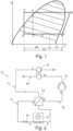
- the 1 shows a pressure-enthalpy diagram (log p/h diagram) for the refrigerant circulating in the cooling circuit 11, which is a zeotropic refrigerant.
- log p/h diagram a pressure-enthalpy diagram for the refrigerant circulating in the cooling circuit 11, which is a zeotropic refrigerant.
- the refrigerant is sucked in and compressed before the compressor 13, so that a pressure corresponding to the position B downstream of the compressor 13 is achieved.
- the refrigerant is compressed by the compressor 13 and then liquefied in the condenser 14 according to position C.
- the refrigerant passes through the internal heat exchanger 19 on the high-pressure side 17 and is further cooled there, so that the position C′ in the direction of flow before the expansion element 15 is reached.
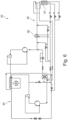
- the 4 shows a cooling device 30 which, in contrast to the cooling device 3 is formed with a first bypass 31 and a second bypass 32.
- a controllable second expansion element 33 is arranged in the first bypass 31 , the first bypass 31 being designed as an internal supplementary cooling system 34 .
- the first bypass 31 is connected to the cooling circuit 24 directly downstream of the condenser 27 upstream of the internal heat exchanger 29 and downstream of the heat exchanger 25 and upstream of the internal heat exchanger 29 in the flow direction.
- the first bypass 31 thus bridges the expansion element 28 with the heat exchanger 25, with the internal heat exchanger 29 evaporating via the second expansion element 33 Refrigerant can be supplied.
Description
Die Erfindung betrifft ein Kältemittel für eine Kühleinrichtung sowie eine Prüfkammer mit dem Kältemittel sowie eine Verwendung eines Kältemittels, wobei das Kältemittel für eine Kühleinrichtung mit einem Kühlkreislauf mit zumindest einem Wärmeübertrager, in dem das Kältemittel eine Phasenänderung durchläuft, aus einem Kältemittelgemisch aus einem Masseanteil Kohlendioxid und einem Masseanteil mindestens einer weiteren Komponente besteht, wobei die weitere Komponente Pentafluorethan und Difluormethan ist.The invention relates to a refrigerant for a cooling device and a test chamber with the refrigerant and a use of a refrigerant, the refrigerant for a cooling device having a cooling circuit with at least one heat exchanger, in which the refrigerant undergoes a phase change, from a refrigerant mixture of a mass fraction of carbon dioxide and a mass fraction of at least one further component, the further component being pentafluoroethane and difluoromethane.
Derartige Kältemittel zirkulieren im Allgemeinen innerhalb eines geschlossenen Kühlkreislaufs von Kühleinrichtungen und erfahren nacheinander verschiedene Änderungen eines Aggregatzustandes. Dabei sollen Kältemittel sollen so beschaffen sein, dass sie in einem Kühlkreislauf innerhalb einer vorgenannten Temperaturdifferenz verwendbar sind. Aus dem Stand der Technik sind sogenannte Einstoffkältemittel und auch Kältemittelgemische aus zumindest zwei Stoffen bekannt. Eine Benennung der Kältemittel erfolgt nach DIN 8960 Absatz 6.Such refrigerants generally circulate within a closed cooling circuit of cooling devices and successively experience various changes in an aggregate state. Refrigerants should be such that they can be used in a cooling circuit within an aforementioned temperature difference. So-called single-component refrigerants and also refrigerant mixtures of at least two substances are known from the prior art. The refrigerants are named according to DIN 8960 paragraph 6.
Infolge gesetzlicher Bestimmungen darf ein Kältemittel nicht wesentlich zum Ozonabbau in der Atmosphäre oder der globalen Erwärmung beitragen. So können im Wesentlichen keine fluorierten Gase oder chlorierten Stoffe als Kältemittel eingesetzt werden, weshalb natürliche Kältemittel beziehungsweise Gase in Frage kommen. Darüber hinaus sollte ein Kältemittel nicht brennbar sein, um unter anderem eine Befüllung, einen Versand und einen Betrieb eines Kühlkreislaufs nicht aufgrund eventuell einzuhaltender Sicherheitsvorschriften zu erschweren. Auch verteuert sich die Herstellung eines Kühlkreislaufs durch die Verwendung eines brennbaren Kältemittels infolge der dadurch erforderlichen konstruktiven Maßnahmen. Unter Brennbarkeit wird hier die Eigenschaft des Kältemittels verstanden, mit Umgebungssauerstoff unter Freisetzung von Wärme zu reagieren. Ein Kältemittel ist insbesondere dann brennbar, wenn es in die Brandklasse C nach der europäischen Norm EN2 beziehungsweise der DIN 378 Klassen A2, A2L und A3 fällt.By law, a refrigerant must not contribute significantly to atmospheric ozone depletion or global warming. Essentially no fluorinated gases or chlorinated substances can be used as refrigerants, which is why natural refrigerants or gases can be considered. In addition, a refrigerant should not be flammable so that, among other things, filling, shipping and operation of a cooling circuit is not made more difficult due to safety regulations that may have to be observed. The production of a cooling circuit also becomes more expensive as a result of the use of a flammable refrigerant as a result of the design measures required as a result. Combustibility is understood here to mean the property of the refrigerant to react with ambient oxygen with the release of heat. A refrigerant is particularly flammable if it falls into fire class C according to the European standard EN2 or DIN 378 classes A2, A2L and A3.
Darüber hinaus sollte ein Kältemittel ein relativ geringes CO2-Äquivalent aufweisen, das heißt ein relatives Treibhauspotential oder auch Global Warming Potential (GWP) sollte möglichst gering sein, um eine indirekte Schädigung der Umwelt durch das Kältemittel bei Freisetzung zu vermeiden. Das GWP gibt an, wieviel eine festgelegte Masse eines Treibhausgases zur globalen Erwärmung beiträgt, wobei als Vergleichswert Kohlendioxid dient. Der Wert beschreibt die mittlere Erwärmungswirkung über einen bestimmten Zeitraum, wobei hier zur Vergleichbarkeit 20 Jahre festgelegt werden. Zur Definition des relativen CO2-Äquivalents beziehungsweise GWPs wird auf den fünften Sachstandsbericht des Intergovernmental Panel on Climate Change (IPCC), Assessment Report, Appendix 8.A, Table 8.A.1 verwiesen.In addition, a refrigerant should have a relatively low CO 2 equivalent, ie a relative greenhouse potential or global warming potential (GWP) should be as low as possible in order to avoid indirect damage to the environment by the refrigerant when it is released. The GWP indicates how much a specified mass of a greenhouse gas contributes to global warming, using carbon dioxide as a comparison value. The value describes the average warming effect over a certain period of time, with 20 years being specified here for comparability. For the definition of the relative CO 2 equivalent or GWP, reference is made to the fifth assessment report of the Intergovernmental Panel on Climate Change (IPCC), Assessment Report, Appendix 8.A, Table 8.A.1.
Nachteilig bei Kältemitteln mit geringem GWP, beispielsweise < 2500, ist, dass diese Kältemittel in den für einen Kühlkreislauf relevanten Temperaturbereichen eine teilweise deutlich verringerte Kälteleistung im Vergleich zu Kältemitteln mit vergleichsweise größerem GWP aufweisen. Mit Kältemittelgemischen, die einen vergleichsweise hohen Masseanteil an Kohlendioxid aufweisen, kann ein niedriger GWP erzielt werden, wobei diese Kältemittelgemische aufgrund der unterschiedlichen, miteinander gemischten Stoffe zeotrope Eigenschaften aufweisen können, was wiederum bei vielen Kühlkreisläufen unerwünscht ist.The disadvantage of refrigerants with a low GWP, for example <2500, is that in the temperature ranges relevant for a cooling circuit, these refrigerants have a partially significantly reduced refrigerating capacity compared to refrigerants with a comparatively larger GWP. A low GWP can be achieved with refrigerant mixtures that have a comparatively high mass fraction of carbon dioxide, with these refrigerant mixtures being able to have zeotropic properties due to the different substances mixed with one another, which in turn is undesirable in many cooling circuits.
Bei einem zeotropen Kältemittelgemisch erfolgt ein Phasenübergang über einen Temperaturbereich, den sogenannten Temperaturglide. Als Temperaturglide wird dabei eine Differenz zwischen der Siedetemperatur und der Taupunkttemperatur bei konstantem Druck angesehen. Bei zeotropen Kältemittelgemischen ist regelmäßig ein hoher Masseanteil einer nicht brennbaren Komponente des Kältemittelgemisches enthalten, wobei diese sich jedoch durch einen vergleichsweise hohen GWP auszeichnet. Kohlendioxid erscheint zunächst als eine Komponente für ein Kältemittelgemisch geeignet, da dieses nicht brennbar ist und einen niedrigen GWP aufweist. Bei einer Mischung von Kohlendioxid mit einer weiteren Komponente ist jedoch wesentlich, dass, sofern die weitere Komponente brennbar ist, ein Masseanteil an Kohlendioxid vergleichsweise groß sein muss. Dies ist jedoch wiederum nachteilig, da Kohlendioxid eine Gefriertemperatur bzw. einen Gefrierpunkt von -56,6 °C aufweist, was eine Erzielung von Temperaturen bis -60 °C bei einer hohen Kohlendioxidkonzentration kaum ermöglicht.In a zeotropic refrigerant mixture, a phase transition takes place over a temperature range, the so-called temperature glide. A difference between the boiling temperature and the dew point temperature at constant pressure is considered a temperature glide. Zeotropic refrigerant mixtures regularly contain a high proportion by mass of a non-flammable component of the refrigerant mixture, which, however, is characterized by a comparatively high GWP. Carbon dioxide initially appears suitable as a component for a refrigerant mixture, since it is non-flammable and has a low GWP. In the case of a mixture of carbon dioxide with a further component, however, it is essential that, if the further component is combustible, a mass fraction of carbon dioxide must be comparatively large. However, this is in turn disadvantageous, since carbon dioxide has a freezing temperature or a freezing point of -56.6° C., which hardly makes it possible to achieve temperatures down to -60° C. with a high carbon dioxide concentration.
Auch sollen Kältemittel möglichst einfach einsetzbar sein, d.h. keinen aufwendigen technischen Umbau einer Kühleinrichtung erfordern. Insbesondere bei Kältemitteln mit einem Temperaturglide > 3 K ist es erforderlich, ein Expansionsorgan und einen Wärmeübertrager bzw. Verdampfer des betreffenden Kühlkreislaufs an die Verdampfungstemperatur des Kältemittels anzupassen und eine entsprechende Regelung vorzusehen. Weiter ist zu unterscheiden zwischen Kältemitteln, die für einen statischen Betrieb einer Kühleinrichtung, d.h. einer Kühleinrichtung mit einer im Wesentlichen über einen längeren Zeitraum konstanten Temperatur am Wärmetauscher bzw. Verdampfer, und einer dynamischen Kühleinrichtung mit einem vergleichsweise schnellen Temperaturwechsel am Wärmeübertrager ausgebildet sind. Derartige dynamische Kühleinrichtungen sind unter anderem in Prüfkammern verbaut, so dass ein verwendetes Kältemittel innerhalb eines großen Temperaturbereichs einsetzbar sein muss.Refrigerants should also be as easy to use as possible, ie they should not require complex technical conversion of a cooling device. Particularly in the case of refrigerants with a temperature glide > 3 K, it is necessary to adapt an expansion device and a heat exchanger or evaporator of the relevant cooling circuit to the evaporation temperature of the refrigerant and to provide appropriate control. A distinction must also be made between refrigerants that are used for static operation of a cooling device, ie a cooling device with a temperature at the heat exchanger or evaporator that is essentially constant over a longer period of time, and dynamic operation Cooling device are formed with a relatively rapid temperature change at the heat exchanger. Such dynamic cooling devices are installed in test chambers, among other things, so that a refrigerant used must be able to be used within a large temperature range.
Prüfkammern werden regelmäßig zur Überprüfung von physikalischen und/oder chemischen Eigenschaften von Gegenständen, insbesondere Vorrichtungen eingesetzt. So sind Temperaturprüfschränke oder Klimaprüfschränke bekannt, innerhalb derer Temperaturen in einem Bereich von -60°C bis +180°C eingestellt werden können. Bei Klimaprüfschränken können ergänzend gewünschte Klimabedingungen eingestellt werden, denen dann die Vorrichtung beziehungsweise das Prüfgut über einen definierten Zeitraum ausgesetzt wird. Derartige Prüfkammern sind regelmäßig beziehungsweise teilweise als ein mobiles Gerät ausgebildet, welches lediglich mit erforderlichen Versorgungsleitungen mit einem Gebäude verbunden ist und alle zur Temperierung und Klimatisierung erforderlichen Baugruppen umfasst. Eine Temperierung eines das zu prüfende Prüfgut aufnehmenden Prüfraums erfolgt regelmäßig in einem Umluftkanal innerhalb des Prüfraums. Der Umluftkanal bildet einen Luftbehandlungsraum im Prüfraum aus, in dem Wärmetauscher zur Erwärmung oder Kühlung der den Umluftkanal beziehungsweise den Prüfraum durchströmenden Luft angeordnet sind. Dabei saugt ein Lüfter beziehungsweise ein Ventilator die im Prüfraum befindliche Luft an und leitet sie im Umluftkanal zu den jeweiligen Wärmetauschern. Das Prüfgut kann so temperiert oder auch einem definierten Temperaturwechsel ausgesetzt werden. Während eines Prüfintervals kann dann eine Temperatur zwischen einem Temperaturmaximum und einem Temperaturminimum der Prüfkammer wiederholt wechseln. Eine derartige Prüfkammer ist beispielsweise aus der
Das in einem Kühlkreislauf zirkulierende Kältemittel muss so beschaffen sein, dass es im Kühlkreislauf innerhalb der vorgenannten Temperaturdifferenz verwendbar ist. Insbesondere kann eine Taupunkttemperatur des Kältemittels nicht höher sein als eine minimale Temperatur des zu erreichenden Temperaturbereiches des Kühlkreislaufs, da sonst bei einem Verdampfen des Kältemittels in dem Wärmeübertrager, der zur Kühlung des Prüfraums dient, die minimale Temperatur nicht erreichbar wäre. Die Taupunkttemperatur von azeotropischen Kältemitteln wird unmittelbar nach dem Expansionsorgan in dem Wärmeübertrager erreicht. Gerade Kühlkreisläufe für Prüfräume erfordern zur präzisen Temperierung der Prüfkammer eine sehr hohe räumliche Temperaturkonstanz, wie sie mit zeotropischen Kältemitteln nicht oder nur mit Einschränkungen erzielbar ist. Eine hohe Temperaturkonstanz ist hier nicht erzielbar, da sich die Taupunkttemperatur beziehungsweise ein Taupunkt des zeotropischen Kältemittels in Abhängigkeit einer Temperatur im Prüfraum im Bereich des Wärmetauschers im Prüfraum durch Temperaturdifferenzen örtlich verschieben kann. Eine Verwendung zeotropischer Kältemittel beziehungsweise von Kältemitteln mit Temperaturglide in Kühlkreisläufen von Prüfkammern wird daher vermieden.The refrigerant circulating in a refrigeration cycle must be such that it is within the aforementioned temperature difference in the refrigeration cycle is usable. In particular, a dew point temperature of the refrigerant cannot be higher than a minimum temperature of the temperature range to be reached in the cooling circuit, since otherwise the minimum temperature would not be achievable if the refrigerant evaporates in the heat exchanger that is used to cool the test chamber. The dew point temperature of azeotropic refrigerants is reached immediately after the expansion device in the heat exchanger. Especially cooling circuits for test rooms require a very high spatial temperature constancy for precise temperature control of the test chamber, which cannot be achieved with zeotropic refrigerants or can only be achieved to a limited extent. A high temperature constancy cannot be achieved here, since the dew point temperature or a dew point of the zeotropic refrigerant can shift locally depending on a temperature in the test room in the area of the heat exchanger in the test room due to temperature differences. The use of zeotropic refrigerants or refrigerants with temperature glide in cooling circuits of test chambers is therefore avoided.
Weiter sind Kühleinrichtungen bekannt, bei denen ein zeotropes Kältemittelgemisch sukzessive verdampft wird. Das heißt Stoffkomponenten des Kältemittels werden nacheinander über ein Expansionsorgan verdampft. Derartige Kühleinrichtungen werden auch als Gemischkaskadenanlage bezeichnet und sind zur Ausbildung einer im Wesentlichen statischen Tieftemperatur geeignet.Cooling devices are also known in which a zeotropic refrigerant mixture is successively evaporated. This means that the material components of the refrigerant are vaporized one after the other via an expansion device. Cooling devices of this type are also referred to as mixture cascade systems and are suitable for forming an essentially static low temperature.
Aus der
Der vorliegenden Erfindung liegt daher die Aufgabe zugrunde, ein Kältemittel für eine Kühleinrichtung, eine Prüfkammer mit einem Kältemittel sowie eine Verwendung eines Kältemittels vorzuschlagen, mit dem beziehungsweise der Temperaturen bis mindestens -60°C umweltfreundlich und sicher erzielbar sind.The present invention is therefore based on the object of proposing a refrigerant for a cooling device, a test chamber with a refrigerant and the use of a refrigerant with which or temperatures down to at least -60°C can be achieved in an environmentally friendly and safe manner.
Diese Aufgabe wird durch ein Kältemittel mit den Merkmalen des Anspruchs 1, eine Prüfkammer mit den Merkmalen des Anspruchs 4 und eine Verwendung eines Kältemittels mit den Merkmalen des Anspruchs 10 gelöst.This object is achieved by a refrigerant having the features of claim 1, a test chamber having the features of claim 4 and the use of a refrigerant having the features of
Bei dem erfindungsgemäßen Kältemittel für eine Kühleinrichtung mit einem Kühlkreislauf mit zumindest einem Wärmeübertrager, durchläuft das Kältemittel in dem Wärmeübertrager eine Phasenänderung, wobei das Kältemittel ein Kältemittelgemisch aus einem Masseanteil Kohlendioxid und einem Masseanteil mindestens einer weiteren Komponente ist, wobei der Masseanteil Kohlendioxid an dem Kältemittelgemisch 33 bis 38 Masseprozent beträgt, wobei die weitere Komponente Pentafluorethan und Difluormethan ist, wobei ein Masseanteil Pentafluorethan 33,5 bis 31 Masseprozent, und ein Masseanteil Difluormethan 33,5 bis 31 Masseprozent beträgt.In the refrigerant according to the invention for a cooling device with a cooling circuit with at least one heat exchanger, the refrigerant in the heat exchanger undergoes a phase change, with the refrigerant being a refrigerant mixture made up of a mass fraction of carbon dioxide and a mass fraction of at least one other component, with the mass fraction of carbon dioxide in the refrigerant mixture being 33 to 38 percent by weight, the further component being pentafluoroethane and difluoromethane, a proportion by weight of pentafluoroethane being 33.5 to 31 percent by weight, and a proportion by weight of difluoromethane being 33.5 to 31 percent by weight.
Kohlendioxid (CO2) ist auch als Kältemittel bzw. Komponente unter der Bezeichnung R744, Pentafluorethan (C2HF5) unter der Bezeichnung R125 und Difluormethan (CH2F2) unter der Bezeichnung R32, Trifluorethylen unter der Bezeichnung R1123, 1,1-Difluorethen (C2H2F2) unter der Bezeichnung R-1132a, Fluorethen (C2H3F) unter der Bezeichnung R1141 gemäß DIN 8960 in der zuletzt gültigen Fassung vor dem Prioritätstag der Anmeldung bekannt.Carbon dioxide (CO 2 ) is also available as a refrigerant or component under the designation R744, pentafluoroethane (C 2 HF 5 ) under the designation R125 and difluoromethane (CH 2 F 2 ) under the designation R32, trifluoroethylene under the designation R1123, 1.1 -Difluoroethene (C 2 H 2 F 2 ) known under the name R-1132a, fluoroethene (C 2 H 3 F) known under the name R1141 according to DIN 8960 in the last valid version before the priority date of the application.
Erfindungsgemäß ist ein Kältemittelgemisch aus Kohlendioxid und einem bzw. mehreren fluorierten Kältemitteln vorgesehen, die einen geringen GWP aufweisen und nicht oder eingeschränkt brennbar sind. Ein Anteil an Kohlendioxid muss dabei möglichst gering sein, da sonst ein Gefrierpunkt des Kältemittelgemisches mit einem steigenden Masseanteil von Kohlendioxid zunimmt. Ein geringerer Masseanteil an Kohlendioxid mindert jedoch eine das GWP reduzierende Wirkung des Kohlendioxids.According to the invention, a refrigerant mixture of carbon dioxide and one or more fluorinated refrigerants is provided, which has a low GWP and is not or only partially flammable. A proportion of carbon dioxide must be as low as possible, since otherwise a freezing point of the refrigerant mixture increases with an increasing mass proportion of carbon dioxide. However, a lower mass fraction of carbon dioxide reduces the GWP-reducing effect of carbon dioxide.
So weisen teilfluorierte Kältemittel einen deutlich höheren GWP als Kohlendioxid auf, wobei diese jedoch auch eine verbesserte brandhemmende Wirkung haben. Insbesondere Pentafluorethan und Difluormethan enthalten eine erhebliche Menge an Fluoratomen, was zu einem unerwünscht hohen GWP führt. Wie sich überraschenderweise herausgestellt hat, kann jedoch mit einem Kältemittelgemisch mit einem Masseanteil Kohlendioxid von 33 bis 38 Masseprozent mit Pentafluorethan und Difluormethan ein ausreichend niedriger GWP, d.h. beispielsweise < 150 erzielt werden. Wie sich ebenfalls herausgestellt hat ist eine brandhemmende Wirkung von Pentafluorethan vergleichsweise größer als die von Kohlendioxid. Durch ein Hinzufügen von Difluormethan als dritte Komponente des Kältemittelgemisches können die negativen Eigenschaften des Pentafluorethans und des Kohlendioxids darüber hinaus reduziert werden. So ist ein Kältemittelgemisch mit Pentafluorethan und Difluormethan als nicht brennbar einzustufen. Gleichzeitig weist Difluormethan mit Kohlendioxid eine tiefere Gefriertemperatur auf als mit Pentafluorethan. Folglich kann mit einem Gemisch aus Pentafluorethan, Difluormethan und Kohlendioxid eine geringere Gefriertemperatur als mit Pentafluorethan und Kohlendioxid alleine erreicht werden. Difluormethan senkt damit den Gefrierpunkt des Kältemittelgemisches signifikant ab, wobei ein bestimmter Masseanteil an Kohlendioxid erforderlich ist, damit das Kältemittelgemisch nicht brennbar ist. Gleichzeitig erzeugt Difluormethan jedoch eine hohe Verdichtungsendtemperatur, weshalb Difluormethan als alleiniger Mischungspartner für Kohlendioxid nur eingeschränkt geeignet ist. Pentafluorethan kann einen Gefrierpunkt des Kältemittelgemisches nicht so weit absenken wie Difluormethan, hat aber eine im Vergleich zu Kohlendioxid höhere flammhemmende Wirkung, was vorteilhaft ist.Partially fluorinated refrigerants have a significantly higher GWP than carbon dioxide, but they also have an improved fire-retardant effect. In particular, pentafluoroethane and difluoromethane contain a significant amount of fluorine atoms, resulting in an undesirably high GWP. As has surprisingly been found, however, a sufficiently low GWP, i.e. <150, for example, can be achieved with a refrigerant mixture with a mass fraction of carbon dioxide of 33 to 38 mass percent with pentafluoroethane and difluoromethane. As has also been found, a fire-retardant effect of pentafluoroethane is comparatively greater than that of carbon dioxide. By adding difluoromethane as the third component of the refrigerant mixture, the negative properties of pentafluoroethane and carbon dioxide can be further reduced. A refrigerant mixture with pentafluoroethane and difluoromethane is classified as non-flammable. At the same time, difluoromethane has a lower freezing temperature with carbon dioxide than with pentafluoroethane. Consequently, a lower freezing temperature can be achieved with a mixture of pentafluoroethane, difluoromethane and carbon dioxide than with pentafluoroethane and carbon dioxide alone. Difluoromethane thus significantly lowers the freezing point of the refrigerant mixture, with a certain mass fraction of carbon dioxide being required so that the refrigerant mixture is non-flammable. At the same time, however, difluoromethane generates a high compression end temperature, which is why difluoromethane is only suitable to a limited extent as the sole mixing partner for carbon dioxide. Pentafluoroethane cannot lower a freezing point of the mixed refrigerant as much as difluoromethane, but has a higher flame retardancy compared to carbon dioxide, which is advantageous.
Das Kohlendioxid ist besonders vorteilhaft mit Pentafluorethan und/oder Difluormethan mischbar, wenn der Masseanteil an Kohlendioxid an dem Kältemittelgemisch 31 bis 46 Masseprozent beträgt. Eine Gefriertemperatur des Kältemittelgemisches kann durch die Zugabe der genannten Komponenten reduziert werden. Die Reduktion kann dabei derart eingestellt werden, dass zum einen der Gefrierpunkt des Kältemittelgemisches niedriger ist als die angestrebte Verdampfungstemperatur und gleichzeitig der zu der Verdampfungstemperatur gehörige Dampfdruck der über oder nur gering unter dem Umgebungsdruck liegen darf.The carbon dioxide is particularly advantageously miscible with pentafluoroethane and/or difluoromethane if the proportion by mass of carbon dioxide in the refrigerant mixture is 31 to 46 percent by mass. A freezing temperature of the refrigerant mixture can be achieved by adding the above components are reduced. The reduction can be set in such a way that the freezing point of the refrigerant mixture is lower than the desired evaporation temperature and at the same time the vapor pressure associated with the evaporation temperature can be above or only slightly below the ambient pressure.
Pentofluorethan ist nicht brennbar, so dass auch alle Gemische mit ihm und Kohlendioxid nicht brennbar sind. Die Gefrierpunktreduktion ist verglichen mit Difluormethan und R1123 weniger stark ausgeprägt. Sein GWP ist mit 3150 deutlich höher als der anderer möglicher Komponenten. Es kann daher auch durch andere Stoffe partiell im Kältemittelgemisch substituiert werden um den GWP des Kältemittelgemisches zu reduzieren. Die brandhemmende Wirkung von Pentofluorethan ist stärker als die von Kohlendioxid, so dass ein Masseanteil an Kohlendioxid im Kältemittelgemisch reduziert werden kann was den Gefrierpunkt weiter senkt, die nicht Brennbarkeit weiterhin gewährleistet aber den GWP erhöht.Pentofluoroethane is non-flammable, so all mixtures with it and carbon dioxide are also non-flammable. The freezing point reduction is less pronounced compared to difluoromethane and R1123. At 3150, its GWP is significantly higher than that of other possible components. It can therefore also be partially substituted by other substances in the refrigerant mixture in order to reduce the GWP of the refrigerant mixture. The fire retardant effect of pentofluoroethane is stronger than that of carbon dioxide, so a mass fraction of carbon dioxide in the refrigerant mixture can be reduced, which further lowers the freezing point, still ensures non-flammability but increases the GWP.
Difluormethan kann als kleines Molekül bezeichnet werden, was dazu führt das bei der Verdichtung von Difluormethan im Vergleich zu größeren und schwereren Molekülen wie Pentofluorethan die Verdichtungsendtemperatur bei gleichen technischen Randbedingungen höher liegt. Die Kältemittel R410A und R410B zeigen niedrigerer Verdichtungsendtemperaturen als Difluormethan, weswegen sie sich insbesondere als Gemischpartner mit Kohlendioxid anbieten.Difluoromethane can be described as a small molecule, which means that when difluoromethane is compressed, the final compression temperature is higher when compared to larger and heavier molecules such as pentofluoroethane with the same technical boundary conditions. The refrigerants R410A and R410B show lower compression end temperatures than difluoromethane, which is why they are particularly suitable as mixture partners with carbon dioxide.
In einer weiteren Ausführungsform kann bei dem Kältemittel ein Masseanteil Kohlendioxid 35 Masseprozent, ein Masseanteil Pentafluorethan 32,5 Masseprozent, und ein Masseanteil Difluormethan 32,5 Masseprozent betragen. Das Kältemittelgemisch kann demnach alleine aus drei Komponenten bestehen. Ein Masseanteil der Komponenten Difluormethan und Pentafluorethan ist dann gleich groß. Wie vorstehend bereits beschrieben, hat sich eine Mischung von Kohlendioxid mit Pentafluorethan und Difluormethan als besonders vorteilhaft herausgestellt. Dieses Kältemittelgemisch kann einen Temperaturgleit > 7 K bei Verdampfungsdrücken um 1 bar aufweisen. Weiter führt dieses Kältemittelgemisch zu einer Reduktion des Gefrierpunktes, welche Konzentrationsabhängig ist. Es können sich daher, bei von den angegebenen Masseanteilen abweichenden Masseanteilen, brennbare und nicht brennbare Kältemittelgemische für unterschiedliche Temperaturanwendungen ergeben.In a further embodiment, in the refrigerant, a mass fraction of carbon dioxide can be 35 mass percent, a mass fraction of pentafluoroethane can be 32.5 mass percent, and a mass fraction of difluoromethane can be 32.5 mass percent. The refrigerant mixture can therefore consist of three components alone. A mass fraction of the components difluoromethane and pentafluoroethane is then equal. As already described above, a mixture of carbon dioxide with pentafluoroethane and difluoromethane has proven particularly advantageous. This Refrigerant mixture can have a temperature glide > 7 K at evaporation pressures around 1 bar. This refrigerant mixture also leads to a reduction in the freezing point, which depends on the concentration. Therefore, if the mass fractions deviate from the specified mass fractions, flammable and non-flammable refrigerant mixtures can result for different temperature applications.
Weiter kann ein Masseanteil Kohlendioxid 35 Masseprozent und ein Masseanteil des Kältemittels R410A 65 Masseprozent betragen. Das Kältemittel R410A enthält gleiche Masseanteile von Pentafluorethan und Difluormethan. Das Kältemittel R410A ist als bereits ausgebildetes Kältemittelgemisch einfach am Markt verfügbar, so dass das Kältemittel lediglich durch Mischen von Kohlendioxid mit R410A kostengünstig und einfach ausgebildet werden kann.Furthermore, a mass fraction of carbon dioxide can be 35 mass percent and a mass fraction of the refrigerant R410A can be 65 mass percent. R410A refrigerant contains equal parts by weight of pentafluoroethane and difluoromethane. The refrigerant R410A is easily available on the market as a refrigerant mixture that has already been formed, so that the refrigerant can be formed inexpensively and easily simply by mixing carbon dioxide with R410A.
In der nachfolgenden Tabelle ist mit dem Beispiel 4 ein Kältemittel entsprechend den zuvor beschriebenen Ausführungsformen angegeben.
Die erfindungsgemäße Prüfkammer zur Konditionierung von Luft umfasst einen gegenüber einer Umgebung verschließbaren und temperaturisolierten Prüfraum zur Aufnahme von Prüfgut, und eine Temperiervorrichtung zur Temperierung des Prüfraums, wobei mittels der Temperiervorrichtung eine Temperatur in einem Temperaturbereich von -60 °C bis +180 °C innerhalb des Prüfraums ausbildbar ist, wobei die Temperiervorrichtung eine Kühleinrichtung mit einem Kühlkreislauf mit einem erfindungsgemäßen Kältemittel, einem Wärmeübertrager, einem Verdichter, einem Kondensator und einem Expansionsorgan aufweist. Zu den Vorteilen der erfindungsgemäßen Prüfkammer wird auf die Vorteilsbeschreibung des erfindungsgemäßen Kältemittels verwiesen.The test chamber according to the invention for conditioning air comprises a test space that can be closed off from the environment and is temperature-insulated for receiving test material, and a temperature control device for temperature control of the test space, with the temperature control device being used to set a temperature in a temperature range from -60 °C to +180 °C within the Test space can be formed, the temperature control device having a cooling device with a cooling circuit with a refrigerant according to the invention, a heat exchanger, a compressor, a condenser and an expansion element. For the advantages of the test chamber according to the invention, reference is made to the description of the advantages of the refrigerant according to the invention.
Mittels der Temperiervorrichtung kann eine Temperatur in einem Temperaturbereich von -60 °C bis +180 °C, bevorzugt -80 °C bis +180 °C, besonders bevorzugt -100 °C bis +180 °C, innerhalb des Prüfraums ausgebildet werden. Im Gegensatz zu einer Gemischkaskadenanlage kann hier das Kältemittel mit allen im Kältemittel enthaltenen Stoffkomponenten gleichzeitig über das Expansionsorgan verdampft werden. Da ein Gefrierpunkt des Kohlendioxids bei -56,6 °C liegt, sind Kältemittelgemische, die einen großen Masseanteil an Kohlendioxid enthalten, prinzipiell nicht mehr zur Erzielung von Temperaturen unter -56,6 °C geeignet. Durch die Verwendung des erfindungsgemäßen Kältemittels wird es jedoch möglich, eine Taupunkttemperatur des Kältemittels von unter -60 °C zu erzielen.A temperature in a temperature range from -60° C. to +180° C., preferably -80° C. to +180° C., particularly preferably -100° C. to +180° C., can be generated within the test chamber by means of the temperature control device. In contrast to a mixture cascade system, the refrigerant can be evaporated here with all the components contained in the refrigerant at the same time via the expansion device. Since the freezing point of carbon dioxide is -56.6 °C, refrigerant mixtures that contain a large proportion by mass of carbon dioxide are in principle no longer suitable for achieving temperatures below -56.6 °C. However, the use of the refrigerant according to the invention makes it possible to achieve a dew point temperature of the refrigerant below -60°C.
Der Kühlkreislauf kann einen internen Wärmeübertrager aufweisen, wobei der interne Wärmeübertrager an einer Hochdruckseite des Kühlkreislaufs in einer Strömungsrichtung vor dem Expansionsorgan und nachfolgend dem Kondensator, und an einer Niederdruckseite des Kühlkreislaufs in einer Strömungsrichtung vor dem Verdichter und nachfolgend dem Wärmeübertrager angeschlossen sein kann. Durch den Einsatz des internen Wärmetauschers und die damit durchgeführte Kühlung des verflüssigten Kältemittels der Hochdruckseite können Temperaturen unter -56 °C leicht erreicht werden. Dabei kann die Verdampfungstemperatur des mittels des internen Wärmeübertragers gekühlten Kältemittels am Expansionsorgan relativ zu einer Verdampfungstemperatur eines ungekühlten Kältemittels abgesenkt werden. Die über den internen Wärmetauscher von der Niederdruckseite auf die Hochdruckseite übertragene Kälteleistung kann somit zumindest teilweise, bevorzugt ausschließlich zur Absenkung der Verdampfungstemperatur des Kältemittels am Expansionsorgan genutzt werden. Weiter wird es überhaupt erst möglich, ein zeotropes Kältemittel mit einem Temperaturglide zu verwenden, da dann der Ort der Taupunkttemperatur des Kältemittels beziehungsweise der Taupunkt des Kältemittels in den internen Wärmeübertrager verschoben werden kann. Infolge des Temperaturglides des zeotropen Kältemittels kann die erzielte Taupunkttemperatur des Kältemittels vergleichsweise hoch sein und so eine weitergehende Abkühlung des Wärmeübertragers verhindern.The refrigeration circuit can have an internal heat exchanger, the internal heat exchanger being on a high-pressure side of the refrigeration circuit in a flow direction before the expansion device and subsequently the condenser, and on a low-pressure side of the refrigeration circuit can be connected in a direction of flow before the compressor and then the heat exchanger. By using the internal heat exchanger and the cooling of the liquefied refrigerant on the high-pressure side that is carried out with it, temperatures below -56 °C can easily be achieved. The evaporation temperature of the refrigerant cooled by means of the internal heat exchanger can be lowered on the expansion element relative to an evaporation temperature of an uncooled refrigerant. The cooling capacity transferred via the internal heat exchanger from the low-pressure side to the high-pressure side can thus be used at least partially, preferably exclusively, to lower the evaporation temperature of the refrigerant on the expansion element. Furthermore, it is only possible to use a zeotropic refrigerant with a temperature glide, since the location of the dew point temperature of the refrigerant or the dew point of the refrigerant can then be shifted into the internal heat exchanger. As a result of the temperature glide of the zeotropic refrigerant, the achieved dew point temperature of the refrigerant can be comparatively high and thus prevent further cooling of the heat exchanger.
Es kann daher nur ein Teil des Kältemittels in dem Wärmeübertrager verdampft und der nicht nutzbare Teil des Nassdampfanteils des Kältemittels in den internen Wärmeübertrager verlagert werden. Insgesamt wird es so möglich, auch Kältemittel mit einem Masseanteil an Kohlendioxid, die einerseits umweltfreundlich sind aber andererseits zeotrope Eigenschaften aufweisen, zur Ausbildung niedriger Temperaturen in einem Prüfraum zu verwenden. Wenn ein Teil des Temperaturglides beziehungsweise ein Teil des Nassdampfes des Kältemittels von dem Wärmeübertrager im Prüfraum in den internen Wärmeübertrager verlagert wird, wird es darüber hinaus möglich, mit dem zeotropen Kältemittel eine vergleichsweise verbesserte Temperaturkonstanz zu erzielen. Eine über den Wärmeübertrager abgegebene Kälteleistung kann dann nur innerhalb eines Abschnitts des Temperaturglides erzeugt werden, so dass eine Verschiebung des Taupunktes des Kältemittels im Kühlkreislauf kaum eine Temperaturkonstanz des Wärmeübertragers beeinflussen kann. Weiter kann vorgesehen sein, dass hier lediglich ein einziger Wärmetauscher zur Kühlung eines Mediums, hier der Luft im Prüfraum, verwendet wird.Therefore, only part of the refrigerant can be evaporated in the heat exchanger and the non-usable part of the wet vapor component of the refrigerant can be relocated to the internal heat exchanger. Overall, it is thus possible to use refrigerants with a mass fraction of carbon dioxide, which on the one hand are environmentally friendly but on the other hand have zeotropic properties, to form low temperatures in a test room. If part of the temperature glide or part of the wet vapor of the refrigerant is shifted from the heat exchanger in the test room to the internal heat exchanger, it is also possible to achieve a comparatively improved temperature consistency with the zeotropic refrigerant. A cooling output delivered via the heat exchanger can then only be generated within a section of the temperature glide, so that a shift in the dew point of the refrigerant in the cooling circuit can hardly affect the temperature constancy of the heat exchanger. Furthermore, it can be provided that here only a single heat exchanger is used for cooling a medium, here the air in the test chamber.
Der Wärmeübertrager kann derart dimensioniert ausgebildet sein, dass das Kältemittel nur teilweise in dem Wärmeübertrager verdampfen kann. Hieraus ergibt sich der Vorteil, dass der Taupunkt beziehungsweise der Ort der Taupunkttemperatur des Kältemittels aus dem Wärmeübertrager heraus, in den internen Wärmeübertrager verschoben werden kann. Aufgrund eines Temperaturglides des zeotropen Kältemittels wird bei dem teilweisen Verdampfen des Kältemittels in dem Wärmeübertrager eine niedrigere Temperatur im Wärmeübertrager erzielt, als bei dem nachfolgenden, restlichen Verdampfen des Kältemittels in dem internen Wärmeübertrager.The heat exchanger can be dimensioned in such a way that the refrigerant can only partially evaporate in the heat exchanger. This results in the advantage that the dew point or the location of the dew point temperature of the refrigerant can be shifted out of the heat exchanger into the internal heat exchanger. Due to a temperature glide of the zeotropic refrigerant, a lower temperature is achieved in the heat exchanger during the partial evaporation of the refrigerant in the heat exchanger than during the subsequent remaining evaporation of the refrigerant in the internal heat exchanger.
In einer Ausführungsform der Prüfkammer kann der Wärmeübertrager in dem Prüfraum angeordnet sein. Auch kann der Wärmeübertrager dann in einem Luftbehandlungsraum des Prüfraums angeordnet sein, so dass von einem Lüfter umgewälzte Luft mit einem Wärmeübertrager in Kontakt gelangen kann. So wird es möglich eine umgewälzte Luftmenge des Prüfraums mittels der Kühleinrichtung über den Wärmeübertrager im Prüfraum direkt abzukühlen. Die Prüfkammer kann dann den Kühlkreislauf als einen alleinigen, einzigen Kühlkreislauf aufweisen. Der Kühlkreislauf ist dann direkt an den Prüfraum angeschlossen.In one embodiment of the test chamber, the heat exchanger can be arranged in the test space. The heat exchanger can then also be arranged in an air treatment room of the test room, so that air circulated by a fan can come into contact with a heat exchanger. This makes it possible to directly cool down a circulated amount of air in the test room by means of the cooling device via the heat exchanger in the test room. The test chamber can then have the cooling circuit as a sole, single cooling circuit. The cooling circuit is then connected directly to the test room.
In einer weiteren Ausführungsform der Prüfkammer kann der Kondensator als ein Kaskaden-Wärmeübertrager eines weiteren Kühlkreislaufs der Kühleinrichtung ausgebildet sein. Demnach kann die Prüfkammer dann zumindest zwei Kühlkreisläufe aufweisen, wobei der Kühlkreislauf eine zweite Stufe der Kühleinrichtung und ein weiterer Kühlkreislauf, der dann dem Kühlkreislauf vorgelagert ist, eine erste Stufe der Kühleinrichtung ausbilden kann. Der Kondensator dient dann als ein Kaskaden-Wärmeübertrager beziehungsweise Wärmeübertrager für den Kühlkreislauf. Bei dieser Ausführungsform einer Prüfkammer wird es möglich, besonders niedrige Temperaturen in dem Prüfraum auszubilden.In a further embodiment of the test chamber, the condenser can be designed as a cascade heat exchanger of a further cooling circuit of the cooling device. Accordingly, the test chamber can then have at least two cooling circuits, wherein the cooling circuit can form a second stage of the cooling device and a further cooling circuit, which is then upstream of the cooling circuit, can form a first stage of the cooling device. The condenser then serves as a cascade heat exchanger or heat exchanger for the cooling circuit. In this embodiment of a test chamber, it is possible to form particularly low temperatures in the test space.
Die Temperiervorrichtung kann eine Heizeinrichtung mit einer Heizung und einem Heiz-Wärmeübertrager in dem Prüfraum aufweisen. Die Heizeinrichtung kann beispielsweise eine elektrische Widerstandsheizung sein, die den Heiz-Wärmeübertrager beheizt, derart, dass über den Heiz-Wärmeübertrager eine Temperaturerhöhung in dem Prüfraum ermöglicht wird. Wenn der Wärmeübertrager und der Heiz-Wärmeübertrager mittels einer Regeleinrichtung zur Kühlung oder Wärmung der im Prüfung umgewälzten Luft gezielt gesteuert werden können, kann mittels der Temperiervorrichtung innerhalb des Prüfraums eine Temperatur in dem vorstehend angegebenen Temperaturbereich ausgebildet werden. Dabei kann unabhängig vom Prüfgut beziehungsweise eines Betriebszustandes des Prüfgutes eine zeitliche Temperaturkonstanz von ±1 K, vorzugsweise ±0,3 K bis ±0,5 K oder kleiner ±0,3 K während eines Prüfintervalls in dem Prüfraum ausgebildet werden. Unter einem Prüfintervall wird je ein Zeitabschnitt eines vollständigen Prüfzeitraums verstanden, in dem das Prüfgut einer im Wesentlichen gleichbleibenden Temperatur oder Klimabedingung ausgesetzt wird. Der Heiz-Wärmeübertrager kann zusammen mit dem Wärmeübertrager des Kühlkreislaufs derart kombiniert sein, dass ein gemeinsamer Wärmeübertragerkörper ausgebildet ist, der vom Kältemittel durchströmbar ist und der Heizelemente einer elektrischen Widerstandsheizung aufweist. Der Kondensator kann mit einer Luftkühlung oder Wasserkühlung oder einer anderen Kühlflüssigkeit ausgebildet sein. Prinzipiell kann der Kondensator mit jedem geeigneten Fluid gekühlt werden. Wesentlich ist, dass die am Kondensator anfallende Wärmelast über die Luftkühlung oder Wasserkühlung so abgeführt wird, dass das Kältemittel so kondensieren kann, dass es vollständig verflüssigt ist.The temperature control device can have a heating device with a heater and a heating heat exchanger in the test chamber. The heating device can be an electrical resistance heater, for example, which heats the heating and heat exchanger in such a way that the heating and heat exchanger allows the temperature in the test chamber to be increased. If the heat exchanger and the heating heat exchanger can be specifically controlled by means of a control device for cooling or heating the air circulated during the test, a temperature in the above-mentioned temperature range can be formed within the test chamber by means of the temperature control device. A temperature constancy of ±1 K, preferably ±0.3 K to ±0.5 K or less than ±0.3 K can be established during a test interval in the test room, independently of the test item or an operating state of the test item. A test interval is understood to mean a time segment of a complete test period in which the test material is exposed to an essentially constant temperature or climatic condition. The heating heat exchanger can be combined with the heat exchanger of the cooling circuit in such a way that a common heat exchanger body is formed, through which the refrigerant can flow and which has heating elements of an electrical resistance heater. The condenser can be designed with air cooling or water cooling or another cooling liquid. In principle, the condenser can be cooled with any suitable fluid. It is essential that the heat load occurring at the condenser is dissipated via air cooling or water cooling in such a way that the refrigerant can condense so that it is completely liquefied.
Im Kühlkreislauf kann ein erster Bypass mit zumindest einem regelbaren zweiten Expansionsorgan ausgebildet sein, wobei der erste Bypass in einer Strömungsrichtung vor dem internen Wärmeübertrager und nachfolgend dem Kondensator an den Kühlkreislauf angeschlossen sein kann, wobei der erste Bypass als regelbare interne Ergänzungskühlung ausgebildet sein kann. Der erste Bypass kann so eine Rückeinspritzeinrichtung für Kältemittel ausbilden. Demnach kann von dem regelbaren zweiten Expansionsorgan im internen Wärmeübertrager auf der Niederdruckseite Kältemittel zugeführt werden. Der erste Bypass kann dann an der Niederdruckseite des Kühlkreislaufs in einer Strömungsrichtung vor dem internen Wärmeübertrager und nachfolgend dem Wärmeübertrager angeschlossen sein. Das durch das zweite Expansionsorgan gekühlte beziehungsweise seinem Temperaturniveau abgesenkte Kältemittel kann dann durch den internen Wärmeübertrager hindurch geleitet werden und eine Kühlung des Kältemittels auf der Hochdruckseite des internen Wärmeübertragers verstärken. Auch wird eine Kühlleistung des internen Wärmeübertragers dadurch noch genauer regelbar.A first bypass with at least one controllable second expansion element can be configured in the cooling circuit, wherein the first bypass can be connected to the cooling circuit upstream of the internal heat exchanger and downstream of the condenser in a direction of flow, wherein the first bypass can be configured as controllable internal supplementary cooling. The first bypass can thus form a return injection device for refrigerant. Accordingly, coolant can be supplied from the controllable second expansion element in the internal heat exchanger on the low-pressure side. The first bypass can then be connected to the low-pressure side of the cooling circuit in a direction of flow upstream of the internal heat exchanger and subsequently the heat exchanger. The refrigerant which has been cooled or whose temperature level has been reduced by the second expansion element can then be conducted through the internal heat exchanger and cooling of the refrigerant on the high-pressure side of the internal heat exchanger can be intensified. A cooling capacity of the internal heat exchanger can also be regulated even more precisely as a result.
In dem Kühlkreislauf kann ein zweiter Bypass mit zumindest einem dritten Expansionsorgan ausgebildet sein, wobei der zweite Bypass das Expansionsorgan in Strömungsrichtung nachfolgend dem Kondensator und vor dem internen Wärmeübertrager überbrückt, wobei über das dritte Expansionsorgan das Kältemittel so dosierbar ist, dass eine Sauggastemperatur und/oder ein Sauggasdruck des Kältemittels auf der Niederdruckseite des Kühlkreislaufs vor dem Verdichter geregelt werden kann. Dadurch kann unter anderem verhindert werden, dass der Verdichter, bei dem es sich beispielsweise um einen Kompressor handeln kann, eventuell überhitzt dann beschädigt wird. Folglich kann über den zweiten Bypass durch Betätigung des dritten Expansionsorgans vor dem Verdichter befindliches gasförmiges Kältemittel durch Zudosieren von noch flüssigem Kältemittel gekühlt werden. Eine Betätigung des dritten Expansionsorgans kann durch eine Steuervorrichtung erfolgen, die ihrerseits mit einem Druck- und/oder Temperatursensor in einem Kühlkreislauf vor dem Verdichter gekoppelt ist. Besonders vorteilhaft ist es, wenn über den zweiten Bypass eine Sauggastemperatur von ≤ 30 °C eingestellt werden kann. Auch kann das Kältemittel so dosiert werden, dass eine Betriebsdauer des Verdichters regelbar ist. Prinzipiell ist es nachteilig, wenn der Verdichter beziehungsweise Kompressor vielfach eingeschaltet und ausgeschaltet wird. Eine Lebensdauer eines Kompressors kann verlängert werden, wenn dieser längere Zeitabschnitte in Betrieb ist. Über den zweiten Bypass kann ein Kältemittel an dem Expansionsorgan oder dem Kondensator vorbeigeführt werden, um beispielsweise ein automatisches Abschalten des Kompressors zu verzögern und eine Betriebsdauer des Kompressors zu verlängern.A second bypass with at least one third expansion element can be configured in the cooling circuit, with the second bypass bypassing the expansion element downstream of the condenser and upstream of the internal heat exchanger in the flow direction, with the refrigerant being able to be metered via the third expansion element in such a way that a suction gas temperature and/or a suction gas pressure of the refrigerant on the low-pressure side of the refrigeration circuit can be regulated before the compressor. Among other things, this can prevent the compressor, which can be a compressor, for example, from overheating and then being damaged. Consequently, gaseous refrigerant located upstream of the compressor can be cooled via the second bypass by actuating the third expansion element by metering in refrigerant that is still liquid. The third expansion element can be actuated by a control device, which in turn is provided with a pressure and/or temperature sensor in a cooling circuit coupled to the compressor. It is particularly advantageous if a suction gas temperature of ≦30° C. can be set via the second bypass. The refrigerant can also be metered in such a way that the operating time of the compressor can be regulated. In principle, it is disadvantageous if the compressor or compressor is switched on and off many times. A lifespan of a compressor can be extended if it is operated for longer periods of time. A refrigerant can be routed past the expansion element or the condenser via the second bypass, for example in order to delay an automatic switch-off of the compressor and to extend the operating time of the compressor.
In dem Kühlkreislauf kann ein weiterer Bypass mit zumindest einem weiteren Expansionsorgan ausgebildet sein, wobei der weitere Bypass den Verdichter in Strömungsrichtung nachfolgend dem Verdichter und vor dem Kondensator überbrückt, derart, dass eine Sauggastemperatur und/oder ein Sauggasdruck des Kältemittels auf der Niederdruckseite des Kühlkreislaufs vor dem Verdichter regelbar sein kann, und/oder dass eine Druckdifferenz zwischen der Hochdruckseite und einer Niederdruckseite des Kühlkreislaufs ausgeglichen werden kann. Der zweite Bypass kann ergänzend mit einem einstellbaren oder regelbaren Ventil, beispielsweise einem Magnetventil ausgestattet sein. Durch die Verbindung von Hochdruckseite und Niederdruckseite über das weitere Expansionsorgan kann sichergestellt werden, dass bei einem Anlagenstillstand das so verdichtete und gasförmige Kältemittel von der Hochdruckseite allmählich auf die Niederdruckseite des Kühlkreislaufs strömt. So wird auch bei geschlossenem Expansionsorgan sichergestellt, dass ein allmählicher Druckausgleich zwischen der Hochdruckseite und der Niederdruckseite erfolgt. Ein Querschnitt des weiteren Expansionsorgans kann dabei so bemessen sein, dass ein Überströmen des Kältemittels von der Hochdruckseite zu der Niederdruckseite einen normalen Betrieb der Kühleinrichtung nur unwesentlich beeinflusst. Gleichwohl kann vorgesehen sein, dass vor dem Verdichter befindliches gasförmiges Kältemittel durch Zudosieren von dem flüssigen Kältemittel über den weiteren Bypass gekühlt wird.A further bypass with at least one further expansion element can be configured in the cooling circuit, with the further bypass bypassing the compressor downstream of the compressor and in front of the condenser in the flow direction in such a way that a suction gas temperature and/or a suction gas pressure of the refrigerant is on the low-pressure side of the cooling circuit the compressor can be regulated, and/or that a pressure difference between the high-pressure side and a low-pressure side of the cooling circuit can be compensated. The second bypass can additionally be equipped with an adjustable or controllable valve, for example a solenoid valve. By connecting the high-pressure side and the low-pressure side via the additional expansion element, it can be ensured that when the system is at a standstill, the gaseous refrigerant compressed in this way gradually flows from the high-pressure side to the low-pressure side of the cooling circuit. This ensures that even when the expansion device is closed, there is a gradual pressure equalization between the high-pressure side and the low-pressure side. A cross section of the further expansion element can be dimensioned in such a way that an overflow of the refrigerant from the high-pressure side to the low-pressure side only has an insignificant effect on normal operation of the cooling device. Nevertheless, it can be provided that the gaseous refrigerant located in front of the compressor is cooled by metering in the liquid refrigerant via the additional bypass.
Der interne Wärmeübertrager kann weiter als eine Unterkühlstrecke oder ein Wärmetauscher, insbesondere Plattenwärmetauscher, ausgebildet sein. Die Unterkühlstrecke kann bereits durch zwei aneinander anliegende Leitungsabschnitte des Kühlkreislaufs ausgebildet sein.The internal heat exchanger can also be designed as a sub-cooling section or a heat exchanger, in particular a plate heat exchanger. The sub-cooling section can already be formed by two line sections of the cooling circuit that are in contact with one another.
Das Expansionsorgan kann ein Drosselorgan und ein Magnetventil aufweisen, wobei über das Drosselorgan und das Magnetventil Kältemittel dosiert werden kann. Das Drosselorgan kann ein einstellbares Ventil oder eine Kapillare sein, über das dann mittels des Magnetventils Kältemittel geleitet wird. Das Magnetventil kann seinerseits mittels einer Regeleinrichtung betätigt werden.The expansion element can have a throttle element and a magnetic valve, it being possible for refrigerant to be metered via the throttle element and the magnetic valve. The throttle element can be an adjustable valve or a capillary, through which refrigerant is then conducted by means of the magnetic valve. The solenoid valve can in turn be actuated by means of a control device.
Auch kann die Temperiervorrichtung eine Regeleinrichtung mit zumindest einem Drucksensor und/oder zumindest einem Temperatursensor in dem Kühlkreislauf umfassen, wobei ein Magnetventil mittels der Regeleinrichtung in Abhängigkeit von einer gemessen Temperatur beziehungsweise eines Drucks betätigt werden kann. Die Regeleinrichtung kann Mittel zur Datenverarbeitung umfassen, die Datensätze von Sensoren verarbeiten und die Magnetventile ansteuern. Eine Regelung einer Funktion der Kühleinrichtung kann dann auch, beispielsweise über ein entsprechendes Computerprogramm, an das verwendete Kältemittel angepasst sein. Weiter kann die Regeleinrichtung eine Betriebsstörung signalisieren und gegebenenfalls eine Abschaltung der Prüfkammer veranlassen, um die Prüfkammer und das Prüfgut vor einer Beschädigung durch kritische oder unerwünschte Betriebszustände der Prüfkammer zu schützen.The temperature control device can also include a control device with at least one pressure sensor and/or at least one temperature sensor in the cooling circuit, wherein a solenoid valve can be actuated by means of the control device depending on a measured temperature or pressure. The control device can include means for data processing, which process data sets from sensors and control the solenoid valves. A regulation of a function of the cooling device can then also be adapted to the refrigerant used, for example via a corresponding computer program. Furthermore, the control device can signal a malfunction and, if necessary, cause the test chamber to be switched off in order to protect the test chamber and the test material from damage due to critical or undesired operating states of the test chamber.
Bei der erfindungsgemäßen Verwendung eines Kältemittels, bestehend aus einem Kältemittelgemisch aus einem Masseanteil Kohlendioxid von 33 bis 38 Masseprozent Masseprozent und einem Masseanteil mindestens einer weiteren Komponente, wobei die weitere Komponente Pentafluorethan und Difluormethan ist, wobei ein Masseanteil Pentafluorethan 33,5 bis 31 Masseprozent, und ein Masseanteil Difluormethan 33,5 bis 31 Masseprozent beträgt, wird das Kältemittel zur Konditionierung von Luft in einem gegenüber einer Umgebung verschließbaren und temperaturisolierten Prüfraum einer Prüfkammer zur Aufnahme von Prüfgut verwendet, wobei mittels einer Kühleinrichtung einer Temperiervorrichtung der Prüfkammer, mit einem Kühlkreislauf mit dem Kältemittel, einem Wärmeübertrager, einem Verdichter, einem Kondensator und einem Expansionsorgan, eine Temperatur in einem Temperaturbereich von -60 °C bis +180 °C, bevorzugt -70 °C bis +180 °C, besonders bevorzugt -80 °C bis +180 °C, innerhalb des Prüfraums ausgebildet wird.When using a refrigerant according to the invention, consisting of a refrigerant mixture of a mass fraction of carbon dioxide from 33 to 38 mass percent mass percent and a mass fraction of at least one other component, the other component being pentafluoroethane and is difluoromethane, with a mass fraction of pentafluoroethane being 33.5 to 31 mass percent and a mass fraction of difluoromethane being 33.5 to 31 mass percent, the refrigerant is used to condition air in a test space of a test chamber that can be closed off from the environment and is temperature-insulated to accommodate test material , a temperature in a temperature range of -60 °C to +180 °C, preferably -70 °C, by means of a cooling device of a temperature control device of the test chamber, with a cooling circuit with the refrigerant, a heat exchanger, a compressor, a condenser and an expansion element to +180 °C, particularly preferably -80 °C to +180 °C, is formed within the test room.
Das Kältemittel kann mittels eines internen Wärmeübertragers des Kühlkreislaufs, angeschlossen an einer Hochdruckseite des Kühlkreislaufs in einer Strömungsrichtung vor dem Expansionsorgan und nachfolgend dem Kondensator, und an einer Niederdruckseite des Kühlkreislaufs in einer Strömungsrichtung vor dem Verdichter und nachfolgend dem Wärmeübertrager, der Hochdruckseite gekühlt werden, wobei die Kühlung des Kältemittels der Hochdruckseite mittels des internen Wärmeübertragers zur Absenkung einer Verdampfungstemperatur am Expansionsorgan genutzt werden kann. Während der Absenkung der Verdampfungstemperatur des Kältemittels der Hochdruckseite kann ein Saugdruck des Kältemittels der Niederdruckseite konstant gehalten werden. Ein größerer anlagentechnischer Aufwand, beispielsweise eine ergänzende Regelung des Saugdrucks, wie auch über eine Regelung des Expansionsorgans in Abhängigkeit des Saugdrucks, ist dann nicht zwingend erforderlich. Insbesondere kann der Verdichter dann auch mit einer konstanten Leistung, unabhängig von einem Betriebszustand des Kühlkreislaufs, betrieben werden. Gerade bei einer Verwendung von Kolbenpumpen als Verdichter ist es wesentlich, dass diese zur Erzielung einer langen Lebensdauer über lange Zeiträume und konstanter Drehzahl im Einsatz sind.The refrigerant can be cooled by means of an internal heat exchanger of the cooling circuit, connected to a high-pressure side of the cooling circuit in a flow direction before the expansion element and downstream of the condenser, and on a low-pressure side of the cooling circuit in a flow direction before the compressor and downstream of the heat exchanger, the high-pressure side, where the cooling of the refrigerant on the high-pressure side can be used by means of the internal heat exchanger to lower an evaporation temperature on the expansion element. During the lowering of the evaporation temperature of the high-pressure side refrigerant, a suction pressure of the low-pressure side refrigerant can be kept constant. A greater outlay in terms of system technology, for example additional regulation of the suction pressure, as well as regulation of the expansion element as a function of the suction pressure, is then not absolutely necessary. In particular, the compressor can then also be operated with a constant power, independently of an operating state of the cooling circuit. When piston pumps are used as compressors, it is essential that they are used over long periods of time and at a constant speed in order to achieve a long service life.
Das Kältemittel der Hochdruckseite kann von dem Kältemittel der Niederdruckseite bei einem konstanten Saugdruck auf der Niederdruckseite mittels des internen Wärmeübertragers gekühlt werden. Folglich kann das Kältemittel kann auf einer Verdampfungsstrecke des Kühlkreislaufs von dem Expansionsorgan bis einschließlich dem internen Wärmeübertrager bei einem konstanten Saugdruck verdampfen. Bei dem konstanten Saugdruck beziehungsweise Verdampfungsdruck des Kältemittels kann dann das Kältemittel von dem Expansionsorgan mit einer niedrigen Verdampfungstemperatur bis hin zu dem internen Wärmeübertrager mit einer hohen Verdampfungstemperatur entsprechend dem Temperaturglide des Kältemittels verdampfen. Die durch den Temperaturglide sich ergebende Taupunkttemperatur kann dabei über der Temperatur des zu kühlenden Mediums beziehungsweise der Luft in dem Prüfraum liegen. Sobald eine Verdampfungstemperatur des Kältemittels bei gleichem Saugdruck der Temperatur der zu kühlenden Luft in dem Prüfraum entspricht, kann keine weitere Abkühlung der Luft erzielt werden. Die Taupunkttemperatur, die im weiteren Wärmetauscher erreicht wird, liegt jedoch noch unter der Flüssigkeitstemperatur des Kältemittels auf der Hochdruckseite des internen Wärmeübertragers, so dass eine Flüssigkeitstemperatur des Kältemittels weiter reduziert werden kann. Demnach kann eine Verdampfungstemperatur nach dem Expansionsorgan ohne eine Veränderung des Saugdrucks abgesenkt und damit eine weitergehende Kühlung der Luft in dem Prüfraum erzielt werden.The high-pressure side refrigerant can be cooled by the low-pressure side refrigerant at a constant suction pressure on the low-pressure side by means of the internal heat exchanger. Consequently, the refrigerant can evaporate at a constant suction pressure on an evaporation path of the refrigeration cycle from the expansion element up to and including the internal heat exchanger. At the constant suction pressure or evaporation pressure of the refrigerant, the refrigerant can then evaporate from the expansion element with a low evaporation temperature to the internal heat exchanger with a high evaporation temperature in accordance with the temperature glide of the refrigerant. The dew point temperature resulting from the temperature glide can be above the temperature of the medium to be cooled or the temperature of the air in the test room. As soon as an evaporation temperature of the refrigerant corresponds to the temperature of the air to be cooled in the test space at the same suction pressure, no further cooling of the air can be achieved. However, the dew point temperature that is reached in the further heat exchanger is still below the liquid temperature of the refrigerant on the high-pressure side of the internal heat exchanger, so that a liquid temperature of the refrigerant can be further reduced. Accordingly, an evaporation temperature downstream of the expansion element can be lowered without changing the suction pressure, and further cooling of the air in the test chamber can thus be achieved.
So kann eine erste Teilmenge des über das Expansionsorgan geleiteten Kältemittels in dem Wärmeübertrager und eine zweite Teilmenge des Kältemittels in dem internen Wärmeübertrager verdampft werden. Eine Verdampfungsstrecke des Kühlkreislaufs, innerhalb dem das Kältemittel verdampft, kann sich von dem Expansionsorgan bis hin zu dem internen Wärmeübertrager erstrecken. Dabei kann die Verdampfungsstrecke durch den internen Wärmeübertrager verlaufen, wobei vorzugsweise ein Taupunkt des Kältemittels an einem Ausgang des internen Wärmeübertragers in Strömungsrichtung vor dem Verdichter liegen kann. Ein Verhältnis der ersten Teilmenge zu der zweiten Teilmenge kann sich während eines Betriebs des Kühlkreislaufs in Abhängigkeit einer Temperatur in dem Prüfraum beziehungsweise an dem Wärmeübertrager verändern. Beispielsweise kann sich bei einer vergleichsweise großen Temperaturdifferenz zwischen der Temperatur des Wärmeübertragers und einer Temperatur im Prüfraum eine beschleunigte Erwärmung des Kältemittels im Wärmeübertrager ergeben, die zu einer Verschiebung des Taupunkts des Kältemittels bis hin zu einem Eingang des internen Wärmeübertragers oder Ausgang des Wärmeübertragers in Strömungsrichtung vor dem Verdichter führt. Eine derartige Verschiebung des Taupunktes kann toleriert werden, so lange noch keine vergleichsweise niedrige Temperatur beziehungsweise Soll-Temperatur im Prüfraum ausgebildet ist. Nähert sich die Temperatur des Wärmetauschers der Temperatur im Prüfraum an, erfolgt eine Verschiebung des Taupunktes und damit eine Vergrößerung der zweiten Teilmenge relativ zur ersten Teilmenge des Kältemittels.In this way, a first subset of the refrigerant routed via the expansion element can be evaporated in the heat exchanger and a second subset of the refrigerant can be evaporated in the internal heat exchanger. An evaporation section of the cooling circuit, within which the refrigerant evaporates, can extend from the expansion element to the internal heat exchanger. In this case, the evaporation section can run through the internal heat exchanger, with a dew point of the refrigerant at an outlet of the internal heat exchanger preferably being able to be in front of the compressor in the direction of flow. A ratio of first subset to the second subset can change during operation of the cooling circuit depending on a temperature in the test chamber or at the heat exchanger. For example, a comparatively large temperature difference between the temperature of the heat exchanger and a temperature in the test room can result in accelerated heating of the refrigerant in the heat exchanger, which can lead to a shift in the dew point of the refrigerant up to an inlet of the internal heat exchanger or an outlet of the heat exchanger in the direction of flow the compressor. Such a shift in the dew point can be tolerated as long as there is no comparatively low temperature or target temperature in the test room. If the temperature of the heat exchanger approaches the temperature in the test room, the dew point shifts and the second subset increases in relation to the first subset of the refrigerant.
Die Absenkung der Verdampfungstemperatur des Kältemittels der Hochdruckseite kann selbstregelnd erfolgen. Je nach Temperatur am Wärmeübertrager kann nicht mehr verdampfendes Kältemittel aus diesem in Strömungsrichtung ausgeleitet werden, da in diesem Fall die Temperatur am Wärmeübertrager nicht mehr ausreicht um einen Phasenwechsel des Kältemittels zu erzeugen. So wird Nassdampf beziehungsweise flüssiges Kältemittel im internen Wärmeübertrager nachverdampft, da hier ein Temperaturunterschied zwischen der Hochdruckseite und der Niederdruckseite immer größer als am Wärmeübertrager sein kann. Wenn mittels des internen Wärmeübertragers eine Temperatur des flüssigen Kältemittels vor dem Expansionsorgan durch den Wärmeaustausch am internen Wärmeübertrager reduziert wird, erhöht sich die Energiedichte des Kältemittels vor dem Expansionsorgan und die damit erzielbare Temperaturdifferenz am Wärmeübertrager. Eine Regelung des Zusammenspiels von Expansionsorgan, Wärmeübertrager und internem Wärmeübertrager ist prinzipiell nicht erforderlich.The lowering of the evaporation temperature of the refrigerant on the high-pressure side can take place in a self-regulating manner. Depending on the temperature at the heat exchanger, refrigerant that is no longer evaporating can be discharged from it in the direction of flow, since in this case the temperature at the heat exchanger is no longer sufficient to generate a phase change in the refrigerant. Wet steam or liquid refrigerant is re-evaporated in the internal heat exchanger, since the temperature difference between the high-pressure side and the low-pressure side can always be greater here than at the heat exchanger. If the temperature of the liquid refrigerant upstream of the expansion element is reduced by means of the internal heat exchanger due to the heat exchange at the internal heat exchanger, the energy density of the refrigerant upstream of the expansion element and the temperature difference that can be achieved at the heat exchanger increase. In principle, it is not necessary to regulate the interaction between the expansion element, the heat exchanger and the internal heat exchanger.
Besonders vorteilhaft ist es, wenn die Kühleinrichtung ausschließlich unterhalb des kritischen Punktes des Kältemittels betrieben wird. Wenn die Kühleinrichtung unterhalb des Tripelpunktes des Kältemittels betrieben wird, kann ein Erreichen eines überkritischen Zustands des Kältemittels ausgeschlossen werden. So ist es dann auch nicht erforderlich, die Kühleinrichtung für einen Betrieb im überkritischen Zustand auszubilden, wodurch Kosten zur Ausbildung der Kühleinrichtung eingespart werden können.It is particularly advantageous if the cooling device is only operated below the critical point of the refrigerant. If the cooling device is operated below the triple point of the refrigerant, it can be ruled out that the refrigerant will reach a supercritical state. It is then also not necessary to design the cooling device for operation in the supercritical state, as a result of which costs for designing the cooling device can be saved.
Der konstante Saugdruck kann insbesondere auch während einer Absenkung der Verdampfungstemperatur des Kältemittels der Hochdruckseite durch den internen Wärmeübertrager aufrechterhalten werden. Demnach ist die Kühlung des Kältemittels der Hochdruckseite über den internen Wärmeübertrager auch zumindest teilweise oder auch ausschließlich zur Absenkung einer Verdampfungstemperatur des Kältemittels am Expansionsorgan nutzbar.In particular, the constant suction pressure can also be maintained by the internal heat exchanger during a reduction in the evaporation temperature of the refrigerant on the high-pressure side. Accordingly, the cooling of the refrigerant on the high-pressure side via the internal heat exchanger can also be used at least partially or exclusively to lower an evaporation temperature of the refrigerant on the expansion element.
Eine Taupunkttemperatur des Kältemittels kann höher sein als eine Minimaltemperatur des Temperaturbereichs. Bei den aus dem Stand der Technik bekannten Prüfkammern ist dann mit einem derartigen Kältemittel nicht mehr die Minimaltemperatur des Temperaturbereichs im Prüfraum ausbildbar, sondern eine vergleichsweise höhere Minimaltemperatur, die im wesentlichen der Taupunkttemperatur des Kältemittels entspricht. Bei der erfindungsgemäßen Prüfkammer kann jedoch ein Kältemittel verwendet werden, dessen Taupunkttemperatur höher ist als eine erzielbare Minimaltemperatur des Temperaturbereichs, da das verflüssigte Kältemittel auf der Hochdruckseite mittels des internen Wärmeübertragers gekühlt werden kann, sodass eine Verdampfungstemperatur des Kältemittels am Expansionsorgan vergleichsweise geringer sein kann.A dew point temperature of the refrigerant can be higher than a minimum temperature of the temperature range. In the test chambers known from the prior art, the minimum temperature of the temperature range in the test chamber can then no longer be formed with such a refrigerant, but rather a comparatively higher minimum temperature which essentially corresponds to the dew point temperature of the refrigerant. In the test chamber according to the invention, however, a refrigerant can be used whose dew point temperature is higher than an achievable minimum temperature of the temperature range, since the liquefied refrigerant on the high-pressure side can be cooled by means of the internal heat exchanger, so that an evaporation temperature of the refrigerant at the expansion element can be comparatively lower.
Das Kältemittel kann bei einem Saugdruck beziehungsweise Verdampfungsdruck in einem Druckbereich von 0,3 bis 5 bar absolut verdampft werden. Der Einsatz des Kältemittels innerhalb dieses Druckbereichs ermöglicht eine kostengünstige Ausbildung des Kühlkreislaufs, da dann keine besonderen, druckstabilen Baugruppen und Komponenten zur Ausbildung der Niederdruckseite des Kühlkreislaufs erforderlich sind.The refrigerant can be evaporated at a suction pressure or evaporation pressure in a pressure range from 0.3 to 5 bar absolute. The use of the refrigerant within this pressure range enables a cost-effective design of the cooling circuit, since then no special, pressure-stable assemblies and components are required to form the low-pressure side of the cooling circuit.
Auch kann das Kältemittel bei einem Kondensationsdruck in einem Druckbereich von 5 bis 35 bar absolut kondensiert werden. Auch hier kann die Hochdruckseite dann mit Baugruppen und Komponenten ausgebildet werden, die nicht an vergleichsweise höhere Drücke angepasst sein müssen.The refrigerant can also be condensed at a condensation pressure in a pressure range from 5 to 35 bar absolute. Here, too, the high-pressure side can then be formed with assemblies and components that do not have to be adapted to comparatively higher pressures.
Weiter kann das verwendete Kältemittel einen Temperaturglide von ≥ 10 K, bevorzugt ≥ 15 K, besonders bevorzugt ≥ 18 K aufweisen. Ein Temperaturglide des Kältemittels sollte dabei nicht > 20 K sein, damit eine Kühleinrichtung sinnvoll betrieben werden kann.Furthermore, the refrigerant used can have a temperature glide of ≧10 K, preferably ≧15 K, particularly preferably ≧18 K. A temperature glide of the refrigerant should not be > 20 K so that a cooling device can be operated sensibly.
Das verwendete Kältemittel kann ein relatives CO2-Äquivalent, bezogen auf 20 Jahre, von < 2500, bevorzugt < 1500, besonders bevorzugt < 500, aufweisen. Folglich kann das Kältemittel wenig umweltschädigend sein.The refrigerant used can have a relative CO 2 equivalent, based on 20 years, of <2500, preferably <1500, particularly preferably <500. Consequently, the refrigerant can be little harmful to the environment.
Das verwendete Kältemittel kann nicht brennbar sein. Wenn das Kältemittel nicht brennbar ist, wird es möglich, den Kühlkreislauf und insbesondere eine Prüfkammer kostengünstiger auszubilden, da keine besonderen Sicherheitsvorkehrungen hinsichtlich Brennbarkeit des Kältemittels zu beachten sind. Das Kältemittel kann dann zumindest nicht der Brandklasse C und/oder der Kältemittelsicherheitsgruppe A1 zugeordnet werden. Darüber hinaus wird ein Versand beziehungsweise ein Transport des Kühlkreislaufs vereinfacht, da der Kühlkreislauf bereits vor einem Transport, unabhängig von der Transportart mit dem Kältemittel befüllt werden kann. Bei brennbarem Kältemittel ist gegebenenfalls erst eine Befüllung im Rahmen einer Inbetriebnahme am Aufstellort möglich. Weiter ist eine Verwendung des nicht brennbaren Kältemittels bei vorhandenen Zündquellen möglich.The refrigerant used cannot be flammable. If the refrigerant is not flammable, it is possible to design the cooling circuit and in particular a test chamber more cost-effectively, since no special safety precautions with regard to the flammability of the refrigerant need to be observed. The refrigerant can then at least not be assigned to fire class C and/or refrigerant safety group A1. In addition, shipping or transport of the cooling circuit is simplified, since the cooling circuit can already be filled with the refrigerant before transport, regardless of the type of transport. In the case of flammable refrigerants, filling may only be possible during commissioning at the installation site. It is also possible to use the non-flammable refrigerant where ignition sources are present.
Weitere Ausführungsformen einer Verwendung ergeben sich aus den Merkmalsbeschreibungen der auf den Vorrichtungsanspruch 1 rückbezogenen Unteransprüche.Further embodiments of a use emerge from the feature descriptions of the dependent claims referring back to the device claim 1 .
Nachfolgend werden bevorzugte Ausführungsformen der Erfindung unter Bezugnahme auf die beigefügten Zeichnungen näher erläutert.Preferred embodiments of the invention are explained in more detail below with reference to the accompanying drawings.
Es zeigen:
- Fig. 1
- ein Druck-Enthalpie-Diagramm für ein Kältemittel;
- Fig. 2
- eine schematische Darstellung einer ersten Ausführungsform einer Kühleinrichtung;
- Fig. 3
- eine schematische Darstellung einer zweiten Ausführungsform einer Kühleinrichtung;
- Fig. 4
- eine schematische Darstellung einer dritten Ausführungsform einer Kühleinrichtung;
- Fig. 5
- eine schematische Darstellung einer vierten Ausführungsform einer Kühleinrichtung;
- Fig. 6
- eine schematische Darstellung einer fünften Ausführungsform einer Kühleinrichtung.
- 1
- a pressure-enthalpy diagram for a refrigerant;
- 2
- a schematic representation of a first embodiment of a cooling device;
- 3
- a schematic representation of a second embodiment of a cooling device;
- 4
- a schematic representation of a third embodiment of a cooling device;
- figure 5
- a schematic representation of a fourth embodiment of a cooling device;
- 6
- a schematic representation of a fifth embodiment of a cooling device.
Die
Die
Bei dem Kältemittel handelt es sich um ein Kältemittelgemisch aus einem Masseanteil Kohlendioxid von 33 bis 38 Masseprozent und einem Masseanteil mindestens einer weiteren Komponente, wobei die weitere Komponente Pentafluorethan und Difluormethan ist. Prinzipiell ist es möglich, in dem Kühlkreislauf 11 und den nachfolgend beschriebenen Kühlkreisläufen das in der vorstehenden Tabelle aufgeführte Kältemittel 4 zu verwenden.The refrigerant is a refrigerant mixture made up of a proportion by mass of carbon dioxide of 33 to 38 percent by mass and a proportion by mass of at least one further component, the further component being pentafluoroethane and difluoromethane. In principle it is possible to use the refrigerant 4 listed in the table above in the
Die
Die
Die
Die
Claims (12)
- A refrigerant for a cooling device (10, 23, 30, 36, 43) having a cooling circuit (11, 24, 39, 44) comprising at least one heat exchanger (12, 25, 47) in which the refrigerant undergoes a phase transition, the refrigerant being a refrigerant mixture composed of a mass fraction of carbon dioxide (CO2) and a mass fraction of at least one other component, the other component being pentafluoroethane (C2HF5) and difluoromethane (CH2F2),
characterized in that
the mass fraction of carbon dioxide in the refrigerant mixture is 33 to 38 mass percent, a mass fraction of pentafluoroethane being 33.5 to 31 mass percent, and a mass fraction of difluoromethane being 33.5 to 31 mass percent. - The refrigerant according to claim 1,
characterized in that
a mass fraction of carbon dioxide is 35 mass percent, a mass fraction of pentafluoroethane is 32.5 mass percent, and a mass fraction of difluoromethane is 32.5 mass percent. - The refrigerant according to claim 1 or 2,
characterized in that
a mass fraction of carbon dioxide is 35 mass percent, and a mass fraction of refrigerant R410A is 65 mass percent. - A test chamber for conditioning air, the test chamber comprising a test space which serves to receive test material and which can be sealed against an environment and is temperature-insulated, and a temperature control device for controlling the temperature of the test space, a temperature in a temperature range of -60 °C to +180 °C being establishable within the test space by means of the temperature control device, the temperature control device having a cooling device (10, 23, 30, 36, 43) comprising a cooling circuit (11, 24, 39, 44) with a refrigerant according to any one of the preceding claims, a heat exchanger (12, 25, 47), a compressor (13, 26), a condenser (14, 27, 38) and an expansion element (15, 28).
- The test chamber according to claim 4,
characterized in that
the cooling circuit (11, 24, 39, 44) has an internal heat exchanger (19, 29, 46), the internal heat exchanger being connected to a high-pressure side (17) of the cooling circuit upstream of the expansion element (15, 28) and downstream of the condenser (14, 27, 38) and to a low-pressure side (18) of the cooling circuit upstream of the compressor (13, 26) and downstream of the heat exchanger (12, 25, 47). - The test chamber according to claim 4 or 5,
characterized in that
the heat exchanger (12, 25, 47) is of such a size that the refrigerant can only partially evaporate in the heat exchanger. - The test chamber according to any one of claims 4 to 6,
characterized in that
the condenser (14, 27, 38) is realized as a cascade heat exchanger (40) of another cooling circuit (36, 43) of the cooling device. - The test chamber according to any one of claims 4 to 7,
characterized in that
the temperature control device has a heating device comprising a heater and a heating heat exchanger in the test space. - The test chamber according to any one of claims 4 to 8,
characterized in that
a first bypass (31) having at least one controllable second expansion element (33) is realized in the cooling circuit (24, 39, 44), the first bypass being connected to the cooling circuit upstream of the internal heat exchanger (29, 46) and downstream of the condenser (27, 38), the first bypass being realized as an additional controllable internal cooling (34). - A use of a refrigerant consisting of a refrigerant mixture composed of a mass fraction of carbon dioxide (CO2) of 33 to 38 mass percent, and a mass fraction of at least one other component, the other component being pentafluoroethane (C2HF5) and difluoromethane (CH2F2), a mass fraction of pentafluoroethane being 33.5 to 31 mass percent, and a mass fraction of difluoromethane being 33.5 to 31 mass percent, for conditioning air in a test space of a test chamber, the test space serving to receive test material and being sealed against an environment and temperature-insulated, a cooling device (10, 23, 30, 36, 43) of a temperature control device of the test chamber, which comprises a cooling circuit (11, 24, 39, 44) with the refrigerant, a heat exchanger (12, 25, 47), a compressor (13, 26), a condenser (14, 27, 38) and an expansion element (15, 25, 28), being used to establish a temperature in a temperature range of -60 °C to +180 °C, preferably -70 °C to +180 °C, particularly preferably -80 °C to +180 °C, within the test space.
- The use according to claim 10,
characterized in that
an internal heat exchanger (19, 29, 46) of the cooling circuit (11, 24, 39, 44), which is connected to a high-pressure side (17) of the cooling circuit upstream of the expansion element (15, 25, 28) and downstream of the condenser (14, 27, 38) and to a low-pressure side (18) of the cooling circuit upstream of the compressor (13, 26) and downstream of the heat exchanger (12, 25, 47), is used to cool the refrigerant of the high-pressure side, the cooling of the refrigerant of the high-pressure side by means of the internal heat exchanger being used to lower an evaporation temperature at the expansion element. - The use according to claim 10 or 11,
characterized in that
the refrigerant of the high-pressure side (17) is cooled by the refrigerant of the low-pressure side (18) at a constant suction pressure on the low-pressure side by means of the internal heat exchanger (19, 29, 46).
Priority Applications (2)
| Application Number | Priority Date | Filing Date | Title |
|---|---|---|---|
| EP21204822.7A EP3964556B1 (en) | 2017-09-08 | 2018-08-23 | Test chamber |
| EP20196966.4A EP3786255A1 (en) | 2017-09-08 | 2018-08-23 | Coolant |
Applications Claiming Priority (3)
| Application Number | Priority Date | Filing Date | Title |
|---|---|---|---|
| DE102017120786 | 2017-09-08 | ||
| DE102017216363.1A DE102017216363A1 (en) | 2017-09-08 | 2017-09-14 | refrigerant |
| PCT/EP2018/072819 WO2019048250A1 (en) | 2017-09-08 | 2018-08-23 | Coolant |
Related Child Applications (4)
| Application Number | Title | Priority Date | Filing Date |
|---|---|---|---|
| EP21204822.7A Division-Into EP3964556B1 (en) | 2017-09-08 | 2018-08-23 | Test chamber |
| EP21204822.7A Division EP3964556B1 (en) | 2017-09-08 | 2018-08-23 | Test chamber |
| EP20196966.4A Division-Into EP3786255A1 (en) | 2017-09-08 | 2018-08-23 | Coolant |
| EP20196966.4A Division EP3786255A1 (en) | 2017-09-08 | 2018-08-23 | Coolant |
Publications (2)
| Publication Number | Publication Date |
|---|---|
| EP3679109A1 EP3679109A1 (en) | 2020-07-15 |
| EP3679109B1 true EP3679109B1 (en) | 2023-06-07 |
Family
ID=65441190
Family Applications (3)
| Application Number | Title | Priority Date | Filing Date |
|---|---|---|---|
| EP21204822.7A Active EP3964556B1 (en) | 2017-09-08 | 2018-08-23 | Test chamber |
| EP18768787.6A Active EP3679109B1 (en) | 2017-09-08 | 2018-08-23 | Coolant |
| EP20196966.4A Pending EP3786255A1 (en) | 2017-09-08 | 2018-08-23 | Coolant |
Family Applications Before (1)
| Application Number | Title | Priority Date | Filing Date |
|---|---|---|---|
| EP21204822.7A Active EP3964556B1 (en) | 2017-09-08 | 2018-08-23 | Test chamber |
Family Applications After (1)
| Application Number | Title | Priority Date | Filing Date |
|---|---|---|---|
| EP20196966.4A Pending EP3786255A1 (en) | 2017-09-08 | 2018-08-23 | Coolant |
Country Status (9)
| Country | Link |
|---|---|
| US (1) | US11584875B2 (en) |
| EP (3) | EP3964556B1 (en) |
| JP (1) | JP2020533474A (en) |
| KR (1) | KR20200051588A (en) |
| CN (1) | CN111183201A (en) |
| DE (3) | DE102017012212A1 (en) |
| ES (2) | ES2965363T3 (en) |
| SG (1) | SG11202001938RA (en) |
| WO (1) | WO2019048250A1 (en) |
Families Citing this family (12)
| Publication number | Priority date | Publication date | Assignee | Title |
|---|---|---|---|---|
| DE102017012212A1 (en) * | 2017-09-08 | 2019-03-14 | Technische Universität Dresden | refrigerant |
| DE102017216361A1 (en) * | 2017-09-14 | 2019-03-14 | Weiss Umwelttechnik Gmbh | Process for the conditioning of air |
| EP3584515B1 (en) * | 2018-06-19 | 2023-08-23 | Weiss Technik GmbH | Test chamber and method |
| DE102019105676B4 (en) * | 2019-03-06 | 2021-05-06 | Weiss Umwelttechnik Gmbh | Refrigerant and its use |
| EP3730587B1 (en) * | 2019-04-26 | 2021-12-08 | Weiss Technik GmbH | Coolant |
| EP3865788A1 (en) * | 2020-02-11 | 2021-08-18 | WEISS UMWELTTECHNIK GmbH | Cooling device, test chamber and method |
| EP3904785B1 (en) | 2020-04-27 | 2022-08-24 | Weiss Technik GmbH | Test chamber and method for conditioning of air |
| IT202100018296A1 (en) * | 2021-07-12 | 2023-01-12 | Irinox S P A | REFRIGERATOR FOR FOOD PRODUCTS |
| CN113801635A (en) * | 2021-09-02 | 2021-12-17 | 上海交通大学 | Binary near-azeotropic refrigerant mixture for new energy automobile heat pump |
| CN113899034A (en) * | 2021-09-27 | 2022-01-07 | 深圳朴坂科技有限公司 | All-weather air conditioning device capable of generating power and outputting power |
| EP4317857A1 (en) | 2022-08-02 | 2024-02-07 | Weiss Technik GmbH | Test chamber and method |
| EP4317843A1 (en) | 2022-08-02 | 2024-02-07 | Weiss Technik GmbH | Test chamber and method for operation |
Citations (1)
| Publication number | Priority date | Publication date | Assignee | Title |
|---|---|---|---|---|
| US20150153076A1 (en) * | 2012-08-23 | 2015-06-04 | Mitsubishi Electric Corporation | Refrigeration apparatus |
Family Cites Families (26)
| Publication number | Priority date | Publication date | Assignee | Title |
|---|---|---|---|---|
| DE3818321A1 (en) | 1988-05-30 | 1989-12-07 | Heraeus Voetsch Gmbh | CLIMATE CHECK CHAMBER |
| CA2105565C (en) * | 1991-03-18 | 2003-11-04 | Robert Gerard Richard | Non-azeotropic refrigerant compositions comprising difluoromethane; 1,1,1-trifluoroethane; or propane |
| DE4116274C2 (en) * | 1991-05-17 | 1998-03-19 | Forschungszentrum Fuer Kaeltet | Refrigerant |
| JPH10502960A (en) * | 1994-07-14 | 1998-03-17 | イー・アイ・デュポン・ドゥ・ヌムール・アンド・カンパニー | Refrigerant composition |
| GB9516921D0 (en) * | 1995-08-18 | 1995-10-18 | Ici Plc | Refrigerant compositions |
| US6176102B1 (en) * | 1998-12-30 | 2001-01-23 | Praxair Technology, Inc. | Method for providing refrigeration |
| WO2001019519A1 (en) * | 1999-09-16 | 2001-03-22 | Mirai Electronics Ab | A climatic test chamber system and a method for the operation thereof |
| US7238299B2 (en) * | 2002-11-01 | 2007-07-03 | Honeywell International Inc. | Heat transfer fluid comprising difluoromethane and carbon dioxide |
| CN101914368A (en) * | 2010-07-09 | 2010-12-15 | 天津大学 | Transcritical power cycle mixed working medium |
| EP2980508B1 (en) * | 2013-03-29 | 2018-01-17 | Panasonic Healthcare Holdings Co., Ltd. | Dual refrigeration device |
| WO2015045355A1 (en) * | 2013-09-27 | 2015-04-02 | パナソニックヘルスケア株式会社 | Refrigeration device |
| CN105579790B (en) * | 2013-09-27 | 2017-04-05 | 松下健康医疗控股株式会社 | Refrigerating plant |
| JP6262035B2 (en) * | 2014-03-14 | 2018-01-17 | Jxtgエネルギー株式会社 | Refrigerator oil and working fluid composition for refrigerator |
| WO2016194847A1 (en) * | 2015-06-01 | 2016-12-08 | 旭硝子株式会社 | Working medium for heat cycle, composition for heat cycle system, and heat cycle system |
| JP6486847B2 (en) * | 2016-02-19 | 2019-03-20 | エスペック株式会社 | Environmental test equipment |
| DE102016204378A1 (en) * | 2016-03-16 | 2017-09-21 | Weiss Umwelttechnik Gmbh | test chamber |
| DE102017012212A1 (en) * | 2017-09-08 | 2019-03-14 | Technische Universität Dresden | refrigerant |
| DE102017216361A1 (en) * | 2017-09-14 | 2019-03-14 | Weiss Umwelttechnik Gmbh | Process for the conditioning of air |
| CN111492030A (en) * | 2017-11-27 | 2020-08-04 | Rpl控股有限公司 | Low GWP refrigerant blends |
| ES2937914T3 (en) * | 2019-01-23 | 2023-04-03 | Weiss Technik Gmbh | Refrigerant |
| EP3686261B1 (en) * | 2019-01-23 | 2024-02-28 | Weiss Technik GmbH | Coolant |
| DE102019105682B4 (en) * | 2019-03-06 | 2022-11-10 | Weiss Technik Gmbh | Refrigerant and its use |
| DE102019105664A1 (en) * | 2019-03-06 | 2020-09-10 | Weiss Umwelttechnik Gmbh | Refrigerant |
| DE102019105676B4 (en) * | 2019-03-06 | 2021-05-06 | Weiss Umwelttechnik Gmbh | Refrigerant and its use |
| EP3865788A1 (en) * | 2020-02-11 | 2021-08-18 | WEISS UMWELTTECHNIK GmbH | Cooling device, test chamber and method |
| EP3910043A1 (en) * | 2020-05-14 | 2021-11-17 | WEISS UMWELTTECHNIK GmbH | Coolant |
-
2017
- 2017-09-14 DE DE102017012212.1A patent/DE102017012212A1/en active Pending
- 2017-09-14 DE DE102017216363.1A patent/DE102017216363A1/en active Pending
- 2017-09-14 DE DE102017012211.3A patent/DE102017012211A1/en active Pending
-
2018
- 2018-08-23 EP EP21204822.7A patent/EP3964556B1/en active Active
- 2018-08-23 ES ES21204822T patent/ES2965363T3/en active Active
- 2018-08-23 SG SG11202001938RA patent/SG11202001938RA/en unknown
- 2018-08-23 EP EP18768787.6A patent/EP3679109B1/en active Active
- 2018-08-23 EP EP20196966.4A patent/EP3786255A1/en active Pending
- 2018-08-23 JP JP2020535296A patent/JP2020533474A/en active Pending
- 2018-08-23 KR KR1020207004907A patent/KR20200051588A/en not_active Application Discontinuation
- 2018-08-23 WO PCT/EP2018/072819 patent/WO2019048250A1/en unknown
- 2018-08-23 ES ES18768787T patent/ES2955048T3/en active Active
- 2018-08-23 US US16/645,143 patent/US11584875B2/en active Active
- 2018-08-23 CN CN201880057748.1A patent/CN111183201A/en active Pending
Patent Citations (1)
| Publication number | Priority date | Publication date | Assignee | Title |
|---|---|---|---|---|
| US20150153076A1 (en) * | 2012-08-23 | 2015-06-04 | Mitsubishi Electric Corporation | Refrigeration apparatus |
Also Published As
| Publication number | Publication date |
|---|---|
| ES2965363T3 (en) | 2024-04-15 |
| DE102017012211A1 (en) | 2019-03-14 |
| JP2020533474A (en) | 2020-11-19 |
| EP3964556B1 (en) | 2023-08-23 |
| EP3786255A1 (en) | 2021-03-03 |
| WO2019048250A1 (en) | 2019-03-14 |
| US20210040366A1 (en) | 2021-02-11 |
| EP3964556A1 (en) | 2022-03-09 |
| US11584875B2 (en) | 2023-02-21 |
| KR20200051588A (en) | 2020-05-13 |
| DE102017012212A1 (en) | 2019-03-14 |
| SG11202001938RA (en) | 2020-04-29 |
| ES2955048T3 (en) | 2023-11-28 |
| DE102017216363A1 (en) | 2019-03-14 |
| CN111183201A (en) | 2020-05-19 |
| EP3679109A1 (en) | 2020-07-15 |
Similar Documents
| Publication | Publication Date | Title |
|---|---|---|
| EP3679109B1 (en) | Coolant | |
| DE102019105676B4 (en) | Refrigerant and its use | |
| EP3430325B1 (en) | Test chamber | |
| EP3705550B1 (en) | Coolant | |
| EP3682175A1 (en) | Air-conditioning method and device | |
| EP3686261B1 (en) | Coolant | |
| EP3705551A1 (en) | Coolant | |
| EP3511695B1 (en) | Test chamber | |
| DE112016000357B4 (en) | Working medium for a heat cycle | |
| EP3686260B1 (en) | Coolant | |
| EP3865788A1 (en) | Cooling device, test chamber and method | |
| EP3584512A1 (en) | Test chamber and method | |
| EP3910043A1 (en) | Coolant | |
| EP3926021A1 (en) | Coolant | |
| EP3699515A1 (en) | Temperature-controlled chamber and method | |
| EP3730587B1 (en) | Coolant | |
| EP3904785B1 (en) | Test chamber and method for conditioning of air | |
| DE102014213542A1 (en) | Method for operating a heat pump with at least two evaporators | |
| EP4317841A1 (en) | Test chamber and method for controlling | |
| DE102019001639A1 (en) | Cooling circuit, heat pump | |
| EP4317857A1 (en) | Test chamber and method |
Legal Events
| Date | Code | Title | Description |
|---|---|---|---|
| STAA | Information on the status of an ep patent application or granted ep patent |
Free format text: STATUS: UNKNOWN |
|
| STAA | Information on the status of an ep patent application or granted ep patent |
Free format text: STATUS: THE INTERNATIONAL PUBLICATION HAS BEEN MADE |
|
| PUAI | Public reference made under article 153(3) epc to a published international application that has entered the european phase |
Free format text: ORIGINAL CODE: 0009012 |
|
| STAA | Information on the status of an ep patent application or granted ep patent |
Free format text: STATUS: REQUEST FOR EXAMINATION WAS MADE |
|
| 17P | Request for examination filed |
Effective date: 20200324 |
|
| AK | Designated contracting states |
Kind code of ref document: A1 Designated state(s): AL AT BE BG CH CY CZ DE DK EE ES FI FR GB GR HR HU IE IS IT LI LT LU LV MC MK MT NL NO PL PT RO RS SE SI SK SM TR |
|
| AX | Request for extension of the european patent |
Extension state: BA ME |
|
| DAV | Request for validation of the european patent (deleted) | ||
| DAX | Request for extension of the european patent (deleted) | ||
| STAA | Information on the status of an ep patent application or granted ep patent |
Free format text: STATUS: EXAMINATION IS IN PROGRESS |
|
| 17Q | First examination report despatched |
Effective date: 20210416 |
|
| RAP3 | Party data changed (applicant data changed or rights of an application transferred) |
Owner name: TECHNISCHE UNIVERSITAET DRESDEN Owner name: WEISS TECHNIK GMBH |
|
| RAP3 | Party data changed (applicant data changed or rights of an application transferred) |
Owner name: TECHNISCHE UNIVERSITAET DRESDEN Owner name: WEISS TECHNIK GMBH |
|
| RIN1 | Information on inventor provided before grant (corrected) |
Inventor name: HAACK, CHRISTIAN Inventor name: HESSE, ULLRICH Inventor name: GOEPFERT, TOBIAS |
|
| GRAP | Despatch of communication of intention to grant a patent |
Free format text: ORIGINAL CODE: EPIDOSNIGR1 |
|
| STAA | Information on the status of an ep patent application or granted ep patent |
Free format text: STATUS: GRANT OF PATENT IS INTENDED |
|
| INTG | Intention to grant announced |
Effective date: 20230110 |
|
| GRAS | Grant fee paid |
Free format text: ORIGINAL CODE: EPIDOSNIGR3 |
|
| GRAA | (expected) grant |
Free format text: ORIGINAL CODE: 0009210 |
|
| STAA | Information on the status of an ep patent application or granted ep patent |
Free format text: STATUS: THE PATENT HAS BEEN GRANTED |
|
| AK | Designated contracting states |
Kind code of ref document: B1 Designated state(s): AL AT BE BG CH CY CZ DE DK EE ES FI FR GB GR HR HU IE IS IT LI LT LU LV MC MK MT NL NO PL PT RO RS SE SI SK SM TR |
|
| REG | Reference to a national code |
Ref country code: GB Ref legal event code: FG4D Free format text: NOT ENGLISH |
|
| RIN1 | Information on inventor provided before grant (corrected) |
Inventor name: HAACK, CHRISTIAN Inventor name: HESSE, ULLRICH Inventor name: GOEPFERT, TOBIAS |
|
| REG | Reference to a national code |
Ref country code: CH Ref legal event code: EP Ref country code: AT Ref legal event code: REF Ref document number: 1574997 Country of ref document: AT Kind code of ref document: T Effective date: 20230615 |
|
| REG | Reference to a national code |
Ref country code: DE Ref legal event code: R096 Ref document number: 502018012389 Country of ref document: DE |
|
| P01 | Opt-out of the competence of the unified patent court (upc) registered |
Effective date: 20230524 |
|
| REG | Reference to a national code |
Ref country code: LT Ref legal event code: MG9D |
|
| REG | Reference to a national code |
Ref country code: NL Ref legal event code: MP Effective date: 20230607 |
|
| PG25 | Lapsed in a contracting state [announced via postgrant information from national office to epo] |
Ref country code: SE Free format text: LAPSE BECAUSE OF FAILURE TO SUBMIT A TRANSLATION OF THE DESCRIPTION OR TO PAY THE FEE WITHIN THE PRESCRIBED TIME-LIMIT Effective date: 20230607 Ref country code: NO Free format text: LAPSE BECAUSE OF FAILURE TO SUBMIT A TRANSLATION OF THE DESCRIPTION OR TO PAY THE FEE WITHIN THE PRESCRIBED TIME-LIMIT Effective date: 20230907 |
|
| PGFP | Annual fee paid to national office [announced via postgrant information from national office to epo] |
Ref country code: IT Payment date: 20230728 Year of fee payment: 6 Ref country code: GB Payment date: 20230710 Year of fee payment: 6 Ref country code: ES Payment date: 20230901 Year of fee payment: 6 |
|
| REG | Reference to a national code |
Ref country code: ES Ref legal event code: FG2A Ref document number: 2955048 Country of ref document: ES Kind code of ref document: T3 Effective date: 20231128 |
|
| PG25 | Lapsed in a contracting state [announced via postgrant information from national office to epo] |
Ref country code: RS Free format text: LAPSE BECAUSE OF FAILURE TO SUBMIT A TRANSLATION OF THE DESCRIPTION OR TO PAY THE FEE WITHIN THE PRESCRIBED TIME-LIMIT Effective date: 20230607 Ref country code: NL Free format text: LAPSE BECAUSE OF FAILURE TO SUBMIT A TRANSLATION OF THE DESCRIPTION OR TO PAY THE FEE WITHIN THE PRESCRIBED TIME-LIMIT Effective date: 20230607 Ref country code: LV Free format text: LAPSE BECAUSE OF FAILURE TO SUBMIT A TRANSLATION OF THE DESCRIPTION OR TO PAY THE FEE WITHIN THE PRESCRIBED TIME-LIMIT Effective date: 20230607 Ref country code: LT Free format text: LAPSE BECAUSE OF FAILURE TO SUBMIT A TRANSLATION OF THE DESCRIPTION OR TO PAY THE FEE WITHIN THE PRESCRIBED TIME-LIMIT Effective date: 20230607 Ref country code: HR Free format text: LAPSE BECAUSE OF FAILURE TO SUBMIT A TRANSLATION OF THE DESCRIPTION OR TO PAY THE FEE WITHIN THE PRESCRIBED TIME-LIMIT Effective date: 20230607 Ref country code: GR Free format text: LAPSE BECAUSE OF FAILURE TO SUBMIT A TRANSLATION OF THE DESCRIPTION OR TO PAY THE FEE WITHIN THE PRESCRIBED TIME-LIMIT Effective date: 20230908 |
|
| PGFP | Annual fee paid to national office [announced via postgrant information from national office to epo] |
Ref country code: FR Payment date: 20230821 Year of fee payment: 6 |
|
| PG25 | Lapsed in a contracting state [announced via postgrant information from national office to epo] |
Ref country code: FI Free format text: LAPSE BECAUSE OF FAILURE TO SUBMIT A TRANSLATION OF THE DESCRIPTION OR TO PAY THE FEE WITHIN THE PRESCRIBED TIME-LIMIT Effective date: 20230607 |
|
| PG25 | Lapsed in a contracting state [announced via postgrant information from national office to epo] |
Ref country code: SK Free format text: LAPSE BECAUSE OF FAILURE TO SUBMIT A TRANSLATION OF THE DESCRIPTION OR TO PAY THE FEE WITHIN THE PRESCRIBED TIME-LIMIT Effective date: 20230607 |
|
| PG25 | Lapsed in a contracting state [announced via postgrant information from national office to epo] |
Ref country code: IS Free format text: LAPSE BECAUSE OF FAILURE TO SUBMIT A TRANSLATION OF THE DESCRIPTION OR TO PAY THE FEE WITHIN THE PRESCRIBED TIME-LIMIT Effective date: 20231007 |
|
| PG25 | Lapsed in a contracting state [announced via postgrant information from national office to epo] |
Ref country code: SM Free format text: LAPSE BECAUSE OF FAILURE TO SUBMIT A TRANSLATION OF THE DESCRIPTION OR TO PAY THE FEE WITHIN THE PRESCRIBED TIME-LIMIT Effective date: 20230607 Ref country code: SK Free format text: LAPSE BECAUSE OF FAILURE TO SUBMIT A TRANSLATION OF THE DESCRIPTION OR TO PAY THE FEE WITHIN THE PRESCRIBED TIME-LIMIT Effective date: 20230607 Ref country code: RO Free format text: LAPSE BECAUSE OF FAILURE TO SUBMIT A TRANSLATION OF THE DESCRIPTION OR TO PAY THE FEE WITHIN THE PRESCRIBED TIME-LIMIT Effective date: 20230607 Ref country code: PT Free format text: LAPSE BECAUSE OF FAILURE TO SUBMIT A TRANSLATION OF THE DESCRIPTION OR TO PAY THE FEE WITHIN THE PRESCRIBED TIME-LIMIT Effective date: 20231009 Ref country code: IS Free format text: LAPSE BECAUSE OF FAILURE TO SUBMIT A TRANSLATION OF THE DESCRIPTION OR TO PAY THE FEE WITHIN THE PRESCRIBED TIME-LIMIT Effective date: 20231007 Ref country code: EE Free format text: LAPSE BECAUSE OF FAILURE TO SUBMIT A TRANSLATION OF THE DESCRIPTION OR TO PAY THE FEE WITHIN THE PRESCRIBED TIME-LIMIT Effective date: 20230607 Ref country code: CZ Free format text: LAPSE BECAUSE OF FAILURE TO SUBMIT A TRANSLATION OF THE DESCRIPTION OR TO PAY THE FEE WITHIN THE PRESCRIBED TIME-LIMIT Effective date: 20230607 |
|
| PGFP | Annual fee paid to national office [announced via postgrant information from national office to epo] |
Ref country code: DE Payment date: 20231023 Year of fee payment: 6 |
|
| PG25 | Lapsed in a contracting state [announced via postgrant information from national office to epo] |
Ref country code: PL Free format text: LAPSE BECAUSE OF FAILURE TO SUBMIT A TRANSLATION OF THE DESCRIPTION OR TO PAY THE FEE WITHIN THE PRESCRIBED TIME-LIMIT Effective date: 20230607 |
|
| REG | Reference to a national code |
Ref country code: DE Ref legal event code: R097 Ref document number: 502018012389 Country of ref document: DE |
|
| PG25 | Lapsed in a contracting state [announced via postgrant information from national office to epo] |
Ref country code: MC Free format text: LAPSE BECAUSE OF FAILURE TO SUBMIT A TRANSLATION OF THE DESCRIPTION OR TO PAY THE FEE WITHIN THE PRESCRIBED TIME-LIMIT Effective date: 20230607 |
|
| REG | Reference to a national code |
Ref country code: CH Ref legal event code: PL |
|
| PG25 | Lapsed in a contracting state [announced via postgrant information from national office to epo] |
Ref country code: MC Free format text: LAPSE BECAUSE OF FAILURE TO SUBMIT A TRANSLATION OF THE DESCRIPTION OR TO PAY THE FEE WITHIN THE PRESCRIBED TIME-LIMIT Effective date: 20230607 |
|
| REG | Reference to a national code |
Ref country code: DE Ref legal event code: R081 Ref document number: 502018012389 Country of ref document: DE Owner name: WEISS TECHNIK GMBH, DE Free format text: FORMER OWNERS: TECHNISCHE UNIVERSITAET DRESDEN, 01069 DRESDEN, DE; WEISS TECHNIK GMBH, 35447 REISKIRCHEN, DE |
|
| PLBE | No opposition filed within time limit |
Free format text: ORIGINAL CODE: 0009261 |
|
| STAA | Information on the status of an ep patent application or granted ep patent |
Free format text: STATUS: NO OPPOSITION FILED WITHIN TIME LIMIT |
|
| PG25 | Lapsed in a contracting state [announced via postgrant information from national office to epo] |
Ref country code: LU Free format text: LAPSE BECAUSE OF NON-PAYMENT OF DUE FEES Effective date: 20230823 |