EP3678950B1 - A machine for conveying containers - Google Patents
A machine for conveying containers Download PDFInfo
- Publication number
- EP3678950B1 EP3678950B1 EP18773848.9A EP18773848A EP3678950B1 EP 3678950 B1 EP3678950 B1 EP 3678950B1 EP 18773848 A EP18773848 A EP 18773848A EP 3678950 B1 EP3678950 B1 EP 3678950B1
- Authority
- EP
- European Patent Office
- Prior art keywords
- pressing device
- carriage
- auxiliary
- constrained
- machine
- Prior art date
- Legal status (The legal status is an assumption and is not a legal conclusion. Google has not performed a legal analysis and makes no representation as to the accuracy of the status listed.)
- Active
Links
Images



Classifications
-
- B—PERFORMING OPERATIONS; TRANSPORTING
- B65—CONVEYING; PACKING; STORING; HANDLING THIN OR FILAMENTARY MATERIAL
- B65G—TRANSPORT OR STORAGE DEVICES, e.g. CONVEYORS FOR LOADING OR TIPPING, SHOP CONVEYOR SYSTEMS OR PNEUMATIC TUBE CONVEYORS
- B65G54/00—Non-mechanical conveyors not otherwise provided for
- B65G54/02—Non-mechanical conveyors not otherwise provided for electrostatic, electric, or magnetic
-
- B—PERFORMING OPERATIONS; TRANSPORTING
- B65—CONVEYING; PACKING; STORING; HANDLING THIN OR FILAMENTARY MATERIAL
- B65C—LABELLING OR TAGGING MACHINES, APPARATUS, OR PROCESSES
- B65C9/00—Details of labelling machines or apparatus
- B65C9/06—Devices for presenting articles in predetermined attitude or position at labelling station
-
- B—PERFORMING OPERATIONS; TRANSPORTING
- B65—CONVEYING; PACKING; STORING; HANDLING THIN OR FILAMENTARY MATERIAL
- B65G—TRANSPORT OR STORAGE DEVICES, e.g. CONVEYORS FOR LOADING OR TIPPING, SHOP CONVEYOR SYSTEMS OR PNEUMATIC TUBE CONVEYORS
- B65G47/00—Article or material-handling devices associated with conveyors; Methods employing such devices
- B65G47/74—Feeding, transfer, or discharging devices of particular kinds or types
- B65G47/88—Separating or stopping elements, e.g. fingers
- B65G47/8807—Separating or stopping elements, e.g. fingers with one stop
- B65G47/8815—Reciprocating stop, moving up or down in the path of the article
-
- B—PERFORMING OPERATIONS; TRANSPORTING
- B65—CONVEYING; PACKING; STORING; HANDLING THIN OR FILAMENTARY MATERIAL
- B65G—TRANSPORT OR STORAGE DEVICES, e.g. CONVEYORS FOR LOADING OR TIPPING, SHOP CONVEYOR SYSTEMS OR PNEUMATIC TUBE CONVEYORS
- B65G2201/00—Indexing codes relating to handling devices, e.g. conveyors, characterised by the type of product or load being conveyed or handled
- B65G2201/02—Articles
- B65G2201/0235—Containers
- B65G2201/0244—Bottles
-
- B—PERFORMING OPERATIONS; TRANSPORTING
- B65—CONVEYING; PACKING; STORING; HANDLING THIN OR FILAMENTARY MATERIAL
- B65G—TRANSPORT OR STORAGE DEVICES, e.g. CONVEYORS FOR LOADING OR TIPPING, SHOP CONVEYOR SYSTEMS OR PNEUMATIC TUBE CONVEYORS
- B65G2205/00—Stopping elements used in conveyors to stop articles or arrays of articles
Definitions
- the present invention relates to a machine for conveying containers. Specifically, the invention relates to the movement mechanism of the press suitable for blocking in position the container transported into the conveying machines.
- the invention relates to the technical field of linear motors and of how these, coupled with conveyor machines, enable transport of containers along the production line.
- conveying machines used for operating on containers are, at least for the most part, of the rotating carousel type.
- the carousel has, on a periphery thereof, predefined container supporting stations (commonly referred to as a "support plate") on which the containers to be treated are positioned.
- the carousel has a central rotation axis and for the support plates has respective rotation axes parallel to the central axis.
- Each support plate is rotatable about itself by taking the movement mechanically from the rotation of the carousel (for example by means of cam members or the like) or, in the most recent machines, is provided with its own electric motor that is commandable by a control unit independently with respect to the rotation of the carousel.
- the container loaded on the support plate can be rotated according to the operating units arranged along the carousel.
- a suitable detecting sensor for example, in order to make errors due to the displacement or falling of the container, it becomes necessary to keep the latter firmly in position on the rotating support plate by use of a jack.
- This constraining system using a jack can be mounted on magnetised carriages, which, coupled with a specific guide, define a linear motor, of which the magnetised carriages are the rotor while the guide is the stator.
- a pressure system which consists of a press that is vertically movable either due to a pneumatic system, for example an air system, or due to a spring system, in which a jack presses the top of a container downwards due to the compressive or extensive work of a spring.
- a first drawback, however, is natural wear on the components used, and in this specific case the spring.
- the spring system is not capable of guaranteeing a constant pressure, as with the case of the pneumatic system, as the force generated depends linearly on the length of the compression or extension of the spring itself (Hooke's law).
- a correct dimensioning of the structure of the device comprising the spring is necessary; in fact, it is usually necessary to have a stroke of about 35 mm for the movement of the jack and for the compression or extension of the spring.
- the pneumatic system even if capable of generating the same pressure all the time, independently of the displacement of the jack, would need a pressure regulator for each valve associated to each container and a rotary air distributor, thus complicating the structure and increasing the final cost.
- a further drawback of the prior art relates to the fact that the rated height of the containers, in reality, is not always the same but can vary by more or less, even by up to a few millimetres, which compromises the operation of the spring system.
- the containers are usually made of glass or plastic, but these two materials are capable of withstanding different maximum pressures, while the spring system is dimensioned such as to work in a single configuration, so changing the containers would make it necessary to reconfigure the whole spring system
- DE 10 2013 100627 A1 discloses a machine for conveying containers, comprising: a guide extending along an advancement direction of the containers; a main carriage slidably mounted on said guide, said guide and said main carriage together defining a main linear motor; at least an auxiliary carriage slidably mounted on said guide, said guide and said auxiliary carriage together defining an auxiliary linear motor; a holding device mounted on said main carriage and mobile between a raised position and a lowered position in which the holding device lifts or lowers the container; a control unit electrically connected to said guide and configured for controlling the sliding of the main carriage and said auxiliary carriage on said guide and a reciprocal distance thereof; actuating means operatively connected to said holding device and configured for moving said holding device between said raised position and said lowered position; said actuating means being operatively interposed between said holding device and said auxiliary carriage, and being activatable following the variation of the reciprocal distance between said main carriage and said auxiliary carriage; said control unit being configured for commanding the variation of the reciprocal distance between the
- DE 10 2010 020958 A1 and DE10 2011 086708 A1 disclose machines for conveying containers with guides and pressing devices mounted on carriages, the carriages forming linear motors with said guides.
- the technical task of the present invention is to provide a machine for conveying containers, which obviates the above-mentioned drawback of the prior art, with reference to a pressing device used to constrain in position a container placed on a rotating support and in movement along a guide of the machine itself.
- An object of the present invention is the possibility of using a constraining system of the container capable of generating always the same pressure on the top of the container, independently of the movement carried out by the pressing device due to the variability of the height of the containers transported.
- a further object of the present invention is the use of a constraining system which does not increase the complexity of the structure of the conveying machine with the addition of electrical circuits or pneumatic systems.
- a final object of the present invention is the use of a constraining system which is capable of operating with both containers made of a plastic material and with glass containers, without any need to have to replace parts, to have to carry out calibrations or to have to use specific positioning sensors.
- the present invention relates to a machine for conveying containers which comprises, at the top of the containers, a guide extending along an advancement direction of the containers, a main carriage and an auxiliary carriage slidably mounted on the guide, with which both the carriages define a linear motor, and a pressing device mounted on the main carriage, which is movable between a raised rest position and a lowered constrained position in which the pressing device applies a pressing force on the top of a container.
- Each container is supported from below by a support plate that is normally mobile and preferably mounted on a carriage which defines a further base linear motor.
- the machine further comprises a control unit electrically connected to the guide and configured for controlling the sliding of the main carriage and the auxiliary carriage on the guide and a mutual distance thereof, and actuating means operatively connected to the pressing device and configured for moving said pressing device between the raised rest position and said lowered constrained position.
- the control unit is configured for commanding the variation of the mutual distance between the main carriage and the auxiliary carriage so as to activate said actuating means, which is operatively interposed between the pressing device and the auxiliary carriage.
- the main carriage and the auxiliary carriage are controllable independently of one another.
- the machine comprises at least two auxiliary carriages slidably mounted on the guide, in such a way that the main carriage is interposed therebetween and each auxiliary carriage is operatively connected to the pressing device by respective actuating means.
- having a main carriage interposed between two auxiliary carriages gives stability to the structure at the time when the pressing device is moved. Further, in a case where both the auxiliary carriages are moved in the same way towards the main carriage, the total force produced will be double that of the same movement of a single auxiliary carriage towards the main carriage.
- the actuating means comprises a linkage, a first end of which is connected to the auxiliary carriage and a second end is connected to the pressing device, so that a variation of the relative distance between said main carriage and at least one auxiliary carriage induces a displacement of the pressing device between the raised rest position and the lowered constrained position.
- this linkage may comprise three levers, each of which has a first end constrained at a same point and a second end constrained at a different point between said pressing means, said main carriage and said auxiliary carriage.
- the actuating means comprises a rack connected to the auxiliary carriage and at least one nut-female screw movement system comprising the pressing device.
- the actuating means comprises at least one connecting rod and at least one crank associated to the connecting rod.
- the connecting rod has a first end constrained to the auxiliary carriage and a second end associated to the crank, while the latter is connected to the pressing device by conversion means for converting the rotary motion into a rectilinear motion.
- the conversion means comprises a screw-female screw movement system which includes the pressing device constrained to the main carriage, in such a way that the rotation of the pressing device is prevented and movement between the raised rest position and the lowered constrained position is enabled.
- the actuating means comprises a linkage, which has a first end constrained to the auxiliary carriage and a second end constrained to a pinion, which is mounted on the main carriage.
- the pinion is also capable of rotating about the constraining point and enables displacement of the pressing device between the raised rest position and the lowered constrained position, as it is associated to a threaded portion thereof, due to the reciprocal displacement between the main carriage and the carriage.
- the actuating means comprises a cam system having at least one shaped profile solidly constrained to the auxiliary carriage and operatively associated to a slider solidly constrained to the pressing device in order to cause movement between said raised rest position and said lowered constrained position.
- the actuating means comprises at least one actuator cylinder comprising a first piston connected to said auxiliary carriage, a second piston connected to said pressing device and a volume of fluid interposed between said first and second pistons.
- the use of one of the suggested actuating means enables having application of a constant pressure value on the top of the container, independently of how much the pressing device has moved from the raised rest position to the lowered constrained position.
- control unit is configured to control the distance between the auxiliary carriage and the main carriage according to the maximum stroke that the pressing device must carry out (for example according to the height of the container). This control is performed by controlling the currents/voltages of the electrical circuits arranged along the guide.
- a limit value of maximum stroke of the pressing device is preferably set, which defines the minimum distance limit between the auxiliary carriage and the main carriage.
- control unit is configured to control the pressure value exerted by the pressing device on the top of the container.
- This pressure value is a function of the force with which the auxiliary carriage pushes towards the main carriage or vice versa.
- a maximum pressure limit value of the pressing device is preferably set, according to the characteristics of the container (for example plastic, glass, .). This maximum pressure value is converted into a maximum current/voltage value which is supplied to the electrical circuits.
- control unit is configured to manage the electrical magnitudes of the electrical circuits of the guide so as to control the thrust force of a carriage towards the other one and thus the pressure of the pressing device on the container.
- control unit is configured to carry out two checks in a parallel way:
- the present invention relates to the technical field of machines for conveying containers, specifically to the constraining system from above of the containers during movement thereof along the production line.
- reference numeral 100 denotes in its entirety a machine for conveying containers, as shown in figure 1 .
- Figure 2 shows, with a schematic bottom view, a guide 1 which extends along an advancement direction 1a of the containers and on which at least one main carriage 2 and at least one auxiliary carriage 3 are mounted.
- the guide 1 can be made up of a plurality of tracks along which the various carriages are arranged, or of a single track electrically connected to a single control unit 5 for better management of the movement of the main carriage 2 and the auxiliary carriage 3.
- the guide 1 is manufactured using a metallic material, generally ferromagnetic, and is electrically connected to a control unit 5 capable of precisely controlling the supply of electric current from a generator, for induction of a specific magnetic field.
- the auxiliary carriage 3 provided with a magnet or made of a conductor material, defines together with the guide 1 a linear motor, where also in this case the guide 1 is the stator and the auxiliary carriage 3 is the rotor.
- the control unit 5 is programmed for a precise control of the electric current to be supplied to a specific portion of the guide 1, in such a way that the latter generates a specific magnetic field for a precise movement of the main carriage 2 and/or of the auxiliary carriage 3.
- the main carriage 2, comprising the pressing device 4, is the carriage carrying out the vertical constraint of the containers during the movement thereof along the production line.
- the pressing device 4 is therefore capable of performing a vertical displacement along an axis coinciding with the main axis of the container, between a raised rest position, in which the pressing device 4 and the container are not in contact, and a lowered constrained position in which the pressing device 4 applies pressure on the top of a container.
- the pressing device 4 is capable of rotating about the main axis in order to follow the rotary movement of the support of the container and, consequently, of the container itself during some operations that take place along the production line, such as labelling.
- the pressing device 4 is rotationally independent of the axial movement between the two positions with respect to a movement axis. In practice, the pressing device 4 does not rotate during the axial movement, but remains idle. In still other words, the pressing device 4 is movable only axially (without rotation).
- the auxiliary carriage 3 is positioned upstream or downstream of the main carriage 2, with respect to the advancement direction 1a of the containers, as it has the function of accompanying the movement of the main carriage 2 in order to be able to impart the vertical translation movement to the pressing device 4.
- the actuating means 6 is interposed between the main carriage 2 and the auxiliary carriage 3, which actuating means 6, once activated, is capable of inducing the vertical translational motion to the pressing device 4 to which the means is operatively associated.
- the main carriage 2 and the auxiliary carriage 3 define a linear motor with the guide 1 and can be translated along the advancement direction 1a of the guide 1 with not necessarily equal specific velocities due to the programming of the control unit 5, which manages position and velocity with great precision, as the mutual distance thereof can be varied in order to activate the operation of the actuating means 6 with the consequent vertical movement of the pressing device 4.
- the actuating means 6 comprises a lever, the ends of which are constrained to the auxiliary carriage 3 and to the pressing device 4.
- the approaching between the main carriage 2 and the auxiliary carriage 3 causes a rotation of the lever about the end constrained to the auxiliary carriage 3 with a consequent vertical downwards displacement of the pressing device 4, constrained to the opposite end of the lever itself.
- the displacement of the pressing device 4 between a raised rest position, in which the main carriage 2 and the auxiliary carriage 3 are at the maximum distance, and a lowered constrained position, in which the main carriage 2 and the auxiliary carriage 3 are at a minimum distance enables application of a pressing force on the container of a first force value (for example 100 N).
- the main carriage 2 can be interposed between two auxiliary carriages 3, each of which has actuating means 6, in the specific case a lever, with a first end constrained to the auxiliary carriage 3 itself and a second end constrained to the pressing device 4.
- actuating means 6 in the specific case a lever
- the relative displacement between the auxiliary carriages 3 and the main carriage 2 imposes a vertical displacement of the pressing device 4.
- the auxiliary carriages 3, having actuating means 6 located mirror-like with respect to the pressing device 4 must synchronously move close to and away from the main carriage 2, generating a pressure on the container that can reach a second force value that is substantially double with respect to the first one (for example 200 N).
- Figure 3c illustrates a further embodying feature of the invention, in which the actuating means 6, interposed between an auxiliary carriage 3 and a main carriage 2, comprises a linkage 10 composed of three levers, each of which has a first end constrained at a same point 11, while each of the second ends 12, 13, 14 is constrained at a different point to the others; specifically they are constrained to the main carriage 2, to the auxiliary carriage 3 and to the pressing device 4.
- the only constraint between the lever and the pressing device 4 is able to translate, as it is capable of translating the pressing device 4 itself. In this way, with respect to the first embodying feature of the invention, it is possible to almost double the pressure that the pressing device 4 is capable of applying to the underlying container.
- Figure 3d illustrates an embodiment of the invention in which the actuating means 6 comprises a rack 20 connected to the auxiliary carriage 3, the relative movement of which with respect to the main carriage 2 leads to the vertical translation of the pressing device 4 due to a screw-female screw movement system 21 associated to the rack 20.
- FIG. 3e A further aspect of the invention is described in figure 3e , in which a main carriage 2 is interposed between two auxiliary carriages 3, and the actuating means 6 capable of moving the pressing device 4 comprises a connecting rod-crank system, one for the connection of each auxiliary carriage 3 with the pressing device 4.
- the crank 31 is located on the main carriage 2 and the rotation axis thereof coincides with the translation axis of the pressing device 4, to which it is operatively connected.
- the connecting rod 30 has a first end 32 constrained to the auxiliary carriage 3 and a second end 33 connected to the crank 31 present on the main carriage 2.
- the variation of the relative distance between the main carriage 2 and the auxiliary carriage 3 activates the connecting rod-crank system, which in turn is capable of imparting the translation motion to the pressing device 4 owing to a conversion system 34 for converting the rotary motion in rectilinear motion comprising a screw-female screw system.
- the two cranks 31 are arranged mutually offset by a non-zero angle of less than 180°, preferably comprised between 45° and 135°, still more preferably 90°.
- Figure 3f shows an aspect of the invention in which the main carriage 2 is interposed between two auxiliary carriages 3, the main carriage 2 being connected to each of them by specific actuating means 6.
- actuating means 6 comprises a linkage 40 having a first end 41 constrained to the auxiliary carriage 3 and a second end 42 constrained to a pinion 43, which is mounted on the main carriage 2 and is able to rotate about the constraining point.
- the variation in the relative distance between the main carriage 2 and the auxiliary carriage 3 causes the movement of the linkage 40, which induces the rotation of the pinion 43 which in turn, being associated to a counter-shaped portion 44 of the pressing device 4, determines the vertical translation of the latter.
- FIG. 3g A further viable aspect of the invention is shown in figure 3g , in which the actuating means 6 interposed between a main carriage 2 and an auxiliary carriage 3 comprises a cam system 50, the shaped profile 51 of which is solidly constrained to the auxiliary carriage 3 and is operatively associated to a slider 52 which is instead solidly constrained to the pressing device 4.
- the movement of the auxiliary carriage 3 and, consequently, of the shaped profile 51 with respect to the main carriage 2 determines the sliding of the slider 52 internally of the shape of the shaped profile 51, forcing the pressing device 4 to make a vertical translation.
- the actuating means 6 comprises an actuator cylinder 60 containing a volume 63 of a compressible fluid interposed between a first piston 61 and a second piston 62.
- the approaching of the auxiliary carriage 3, to which the first piston 61 is connected, to the main carriage 2 determines the compression of the volume 63 of the fluid in the actuator cylinder 60 by the first piston 61, with a consequent displacement of the second piston 62, to which the pressing device 4 is connected, in order to maintain the condition of balance of the system.
- the horizontal translation of the first piston 61 generates a vertical translation of the second piston 62, and thus the vertical translation of the pressing device 4 between a raised rest position and a lowered constrained position.
- the machine 100 is normally inserted in a broader context of a system for conveying containers in which each container is directed (by a guide 1, spacing means and an input star) on a plate of the machine 100 which transports the container along the advancement direction 1a up to an outlet star for extracting the container from the machine 100 itself.
- the machine 100 preferably comprises a base guide arranged below the containers on which carriages for transport of the containers are mounted.
- a rotating plate is mounted on each carriage to set a respective container in rotation.
- Each carriage with the guide in turn defines a base linear motor for transport of the container.
- the guide 1 is arranged above the base guide and the two guides preferably extend substantially parallel to one another. Further, the movement of the base carriage is synchronised with the movement of the main carriage 2 so that the container remains upright.
- each container passes through various units each capable of carrying out different tasks, for example, initially the first device that encounters the container is a detecting device which samples the profile of the container in the search for a recognition sign with respect to which the first label is to be applied, then the container encounters a first labelling unit which applies the first label and, possibly, other work units with different purposes.
- the first device that encounters the container is a detecting device which samples the profile of the container in the search for a recognition sign with respect to which the first label is to be applied
- the container encounters a first labelling unit which applies the first label and, possibly, other work units with different purposes.
- the container In addition to being moved along the advancement direction 1a of the guide 1, the container is also set in rotation about a main axis thereof, so that the operating station, stationary with respect to the guide 1, can carry out the functions for which it is programmed, such as the orientation and the application of labels.
- a pressing device 4 due to actuating means 6 operatively connected, applies a pressing force from above in a downwards direction in order to keep the container in position during the movement and carrying-out of the operations in the work stations.
- the pressing device 4 is installed on a main carriage 2 slidably mounted on the guide 1, mirror-like with respect to the guide used for transport of the containers but superiorly distanced, as it is thus capable of following the translational and rotational movements of the container along the advancement direction 1a.
- the pressing device 4 and the actuating means 6 advantageously do not comprise a spring.
Landscapes
- Engineering & Computer Science (AREA)
- Mechanical Engineering (AREA)
- Transmission Devices (AREA)
- Specific Conveyance Elements (AREA)
- Press Drives And Press Lines (AREA)
- Special Conveying (AREA)
Description
- The present invention relates to a machine for conveying containers. Specifically, the invention relates to the movement mechanism of the press suitable for blocking in position the container transported into the conveying machines.
- The invention relates to the technical field of linear motors and of how these, coupled with conveyor machines, enable transport of containers along the production line.
- At present, conveying machines used for operating on containers are, at least for the most part, of the rotating carousel type. The carousel has, on a periphery thereof, predefined container supporting stations (commonly referred to as a "support plate") on which the containers to be treated are positioned. In particular, the carousel has a central rotation axis and for the support plates has respective rotation axes parallel to the central axis. Each support plate is rotatable about itself by taking the movement mechanically from the rotation of the carousel (for example by means of cam members or the like) or, in the most recent machines, is provided with its own electric motor that is commandable by a control unit independently with respect to the rotation of the carousel. In this way, the container loaded on the support plate can be rotated according to the operating units arranged along the carousel. For example, in order to carry out labelling operations on the container, it is necessary to perform a preliminary rotation of the container on itself in order to detect the application position of the label (by means of a suitable detecting sensor) in order then to arrange the container in the position prior to or at the labelling unit. During this procedure, in order not to make errors due to the displacement or falling of the container, it becomes necessary to keep the latter firmly in position on the rotating support plate by use of a jack. This constraining system using a jack, as illustrated in patent
WO2017103813 , can be mounted on magnetised carriages, which, coupled with a specific guide, define a linear motor, of which the magnetised carriages are the rotor while the guide is the stator. - However, the present technology has some drawbacks that the invention seeks to obviate.
- In fact, for this purpose a pressure system is normally used, which consists of a press that is vertically movable either due to a pneumatic system, for example an air system, or due to a spring system, in which a jack presses the top of a container downwards due to the compressive or extensive work of a spring.
- A first drawback, however, is natural wear on the components used, and in this specific case the spring.
- Further, the spring system is not capable of guaranteeing a constant pressure, as with the case of the pneumatic system, as the force generated depends linearly on the length of the compression or extension of the spring itself (Hooke's law). Once the spring has been chosen, which is characterised by a specific elastic constant value, a correct dimensioning of the structure of the device comprising the spring is necessary; in fact, it is usually necessary to have a stroke of about 35 mm for the movement of the jack and for the compression or extension of the spring. Alternatively, the pneumatic system, even if capable of generating the same pressure all the time, independently of the displacement of the jack, would need a pressure regulator for each valve associated to each container and a rotary air distributor, thus complicating the structure and increasing the final cost.
- A further drawback of the prior art relates to the fact that the rated height of the containers, in reality, is not always the same but can vary by more or less, even by up to a few millimetres, which compromises the operation of the spring system.
- Lastly, the containers are usually made of glass or plastic, but these two materials are capable of withstanding different maximum pressures, while the spring system is dimensioned such as to work in a single configuration, so changing the containers would make it necessary to reconfigure the whole spring system
-
DE 10 2013 100627 A1 discloses a machine for conveying containers, comprising: a guide extending along an advancement direction of the containers; a main carriage slidably mounted on said guide, said guide and said main carriage together defining a main linear motor; at least an auxiliary carriage slidably mounted on said guide, said guide and said auxiliary carriage together defining an auxiliary linear motor; a holding device mounted on said main carriage and mobile between a raised position and a lowered position in which the holding device lifts or lowers the container; a control unit electrically connected to said guide and configured for controlling the sliding of the main carriage and said auxiliary carriage on said guide and a reciprocal distance thereof; actuating means operatively connected to said holding device and configured for moving said holding device between said raised position and said lowered position; said actuating means being operatively interposed between said holding device and said auxiliary carriage, and being activatable following the variation of the reciprocal distance between said main carriage and said auxiliary carriage; said control unit being configured for commanding the variation of the reciprocal distance between the main carriage and the auxiliary carriage so as to activate said actuating means. -
DE 10 2010 020958 A1 andDE10 2011 086708 A1 disclose machines for conveying containers with guides and pressing devices mounted on carriages, the carriages forming linear motors with said guides. - In this context, the technical task of the present invention is to provide a machine for conveying containers, which obviates the above-mentioned drawback of the prior art, with reference to a pressing device used to constrain in position a container placed on a rotating support and in movement along a guide of the machine itself.
- An object of the present invention is the possibility of using a constraining system of the container capable of generating always the same pressure on the top of the container, independently of the movement carried out by the pressing device due to the variability of the height of the containers transported.
- A further object of the present invention is the use of a constraining system which does not increase the complexity of the structure of the conveying machine with the addition of electrical circuits or pneumatic systems.
- Lastly, a final object of the present invention is the use of a constraining system which is capable of operating with both containers made of a plastic material and with glass containers, without any need to have to replace parts, to have to carry out calibrations or to have to use specific positioning sensors.
- In general, the present invention relates to a machine for conveying containers which comprises, at the top of the containers, a guide extending along an advancement direction of the containers, a main carriage and an auxiliary carriage slidably mounted on the guide, with which both the carriages define a linear motor, and a pressing device mounted on the main carriage, which is movable between a raised rest position and a lowered constrained position in which the pressing device applies a pressing force on the top of a container.
- Each container is supported from below by a support plate that is normally mobile and preferably mounted on a carriage which defines a further base linear motor.
- The machine further comprises a control unit electrically connected to the guide and configured for controlling the sliding of the main carriage and the auxiliary carriage on the guide and a mutual distance thereof, and actuating means operatively connected to the pressing device and configured for moving said pressing device between the raised rest position and said lowered constrained position.
- The control unit is configured for commanding the variation of the mutual distance between the main carriage and the auxiliary carriage so as to activate said actuating means, which is operatively interposed between the pressing device and the auxiliary carriage. In other words, the main carriage and the auxiliary carriage are controllable independently of one another.
- Preferably, the machine comprises at least two auxiliary carriages slidably mounted on the guide, in such a way that the main carriage is interposed therebetween and each auxiliary carriage is operatively connected to the pressing device by respective actuating means.
- Advantageously, having a main carriage interposed between two auxiliary carriages gives stability to the structure at the time when the pressing device is moved. Further, in a case where both the auxiliary carriages are moved in the same way towards the main carriage, the total force produced will be double that of the same movement of a single auxiliary carriage towards the main carriage.
- According to a first aspect of the invention, the actuating means comprises a linkage, a first end of which is connected to the auxiliary carriage and a second end is connected to the pressing device, so that a variation of the relative distance between said main carriage and at least one auxiliary carriage induces a displacement of the pressing device between the raised rest position and the lowered constrained position.
- It is further possible for this linkage to comprise three levers, each of which has a first end constrained at a same point and a second end constrained at a different point between said pressing means, said main carriage and said auxiliary carriage.
- According to a second aspect of the invention, the actuating means comprises a rack connected to the auxiliary carriage and at least one nut-female screw movement system comprising the pressing device. According to a third aspect of the invention, the actuating means comprises at least one connecting rod and at least one crank associated to the connecting rod. The connecting rod has a first end constrained to the auxiliary carriage and a second end associated to the crank, while the latter is connected to the pressing device by conversion means for converting the rotary motion into a rectilinear motion.
- Preferably, the conversion means comprises a screw-female screw movement system which includes the pressing device constrained to the main carriage, in such a way that the rotation of the pressing device is prevented and movement between the raised rest position and the lowered constrained position is enabled.
- According to a fourth aspect of the invention, the actuating means comprises a linkage, which has a first end constrained to the auxiliary carriage and a second end constrained to a pinion, which is mounted on the main carriage. The pinion is also capable of rotating about the constraining point and enables displacement of the pressing device between the raised rest position and the lowered constrained position, as it is associated to a threaded portion thereof, due to the reciprocal displacement between the main carriage and the carriage.
- According to a fifth aspect of the invention, the actuating means comprises a cam system having at least one shaped profile solidly constrained to the auxiliary carriage and operatively associated to a slider solidly constrained to the pressing device in order to cause movement between said raised rest position and said lowered constrained position.
- According to a sixth aspect of the invention, the actuating means comprises at least one actuator cylinder comprising a first piston connected to said auxiliary carriage, a second piston connected to said pressing device and a volume of fluid interposed between said first and second pistons.
- Independently of the selected aspect of the invention, the use of one of the suggested actuating means, with respect to the traditional use of a spring, enables having application of a constant pressure value on the top of the container, independently of how much the pressing device has moved from the raised rest position to the lowered constrained position.
- In particular, the control unit is configured to control the distance between the auxiliary carriage and the main carriage according to the maximum stroke that the pressing device must carry out (for example according to the height of the container). This control is performed by controlling the currents/voltages of the electrical circuits arranged along the guide.
- A limit value of maximum stroke of the pressing device is preferably set, which defines the minimum distance limit between the auxiliary carriage and the main carriage.
- Alternatively or additionally, the control unit is configured to control the pressure value exerted by the pressing device on the top of the container. This pressure value is a function of the force with which the auxiliary carriage pushes towards the main carriage or vice versa.
- A maximum pressure limit value of the pressing device is preferably set, according to the characteristics of the container (for example plastic, glass, ....). This maximum pressure value is converted into a maximum current/voltage value which is supplied to the electrical circuits.
- In fact, as the force developed by the linear motor is proportional to the current/voltage which is supplied into the electrical circuits arranged along the guide, the control unit is configured to manage the electrical magnitudes of the electrical circuits of the guide so as to control the thrust force of a carriage towards the other one and thus the pressure of the pressing device on the container.
- In the preferred case, the control unit is configured to carry out two checks in a parallel way:
- a first mutual distance check of the carriages so that the distance does not exceed the predefined maximum stroke limit;
- a second pressure check of the pressing device on the container so that it does not exceed the maximum pressure limit value.
- Further characteristics and advantages of the present invention will become more apparent from the general and thus non-limiting description of a preferred, but not exclusive, embodiment of a machine for conveying containers, as illustrated in the accompanying drawings, in which:
- ▪
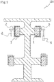
figure 1 illustrates, in a schematic front view, a machine for conveying containers; - ▪
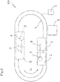
figure 2 illustrates, in a schematic bottom view, the sliding guide for sliding the carriages to constrain the containers; - ▪
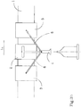
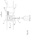
figure 3a illustrates, in a schematic side view, a first embodiment of the machine of the invention with a first type of actuating means; - ▪
figure 3b illustrates, in a schematic side view, a second embodiment of the machine of the invention with a second type of actuating means; - ▪
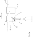
figure 3c illustrates, in a schematic side view, a third embodiment of the machine of the invention with a third type of actuating means; - ▪
figure 3d illustrates, in a schematic side view, a fourth embodiment of the machine of the invention with a fourth type of actuating means; - ▪
figure 3e illustrates, in a schematic side view, a fifth embodiment of the machine of the invention with a fifth type of actuating means; - ▪
figure 3f illustrates, in a schematic side view, a sixth embodiment of the machine of the invention with a sixth type of actuating means; - ▪
figure 3g illustrates, in a schematic side view, a seventh embodiment of the machine of the invention with a seventh type of actuating means; - ▪
figure 3h illustrates, in a schematic side view, an eighth embodiment of the machine of the invention with an eighth type of actuating means. - In the following description, the same reference characters denote the same or corresponding parts in the various views.
- The present invention relates to the technical field of machines for conveying containers, specifically to the constraining system from above of the containers during movement thereof along the production line.
- With reference to the cited figures,
reference numeral 100 denotes in its entirety a machine for conveying containers, as shown infigure 1 . -
Figure 2 shows, with a schematic bottom view, aguide 1 which extends along anadvancement direction 1a of the containers and on which at least onemain carriage 2 and at least oneauxiliary carriage 3 are mounted. Theguide 1 can be made up of a plurality of tracks along which the various carriages are arranged, or of a single track electrically connected to asingle control unit 5 for better management of the movement of themain carriage 2 and theauxiliary carriage 3. - The
guide 1 is manufactured using a metallic material, generally ferromagnetic, and is electrically connected to acontrol unit 5 capable of precisely controlling the supply of electric current from a generator, for induction of a specific magnetic field. Themain carriage 2, equipped with a magnet or produced with a conductor material, defines a linear motor together with theguide 1 supplied with electric current, in which theguide 1 acts as a stator and themain carriage 2 as a rotor. Likewise, theauxiliary carriage 3, provided with a magnet or made of a conductor material, defines together with theguide 1 a linear motor, where also in this case theguide 1 is the stator and theauxiliary carriage 3 is the rotor. Thecontrol unit 5 is programmed for a precise control of the electric current to be supplied to a specific portion of theguide 1, in such a way that the latter generates a specific magnetic field for a precise movement of themain carriage 2 and/or of theauxiliary carriage 3. In fact, it is possible to control the position and velocity of each single carriage, so that on the passage in proximity of theoperating station 8, for example a labelling station, the carriages move with an adequate velocity for carrying out the necessary operations. - The
main carriage 2, comprising thepressing device 4, is the carriage carrying out the vertical constraint of the containers during the movement thereof along the production line. Thepressing device 4 is therefore capable of performing a vertical displacement along an axis coinciding with the main axis of the container, between a raised rest position, in which thepressing device 4 and the container are not in contact, and a lowered constrained position in which thepressing device 4 applies pressure on the top of a container. In addition to be able to vertically constrain the container, thepressing device 4 is capable of rotating about the main axis in order to follow the rotary movement of the support of the container and, consequently, of the container itself during some operations that take place along the production line, such as labelling. - In other words, the
pressing device 4 is rotationally independent of the axial movement between the two positions with respect to a movement axis. In practice, thepressing device 4 does not rotate during the axial movement, but remains idle. In still other words, thepressing device 4 is movable only axially (without rotation). - The
auxiliary carriage 3 is positioned upstream or downstream of themain carriage 2, with respect to theadvancement direction 1a of the containers, as it has the function of accompanying the movement of themain carriage 2 in order to be able to impart the vertical translation movement to thepressing device 4. - As shown in
figure 2 , the actuating means 6 is interposed between themain carriage 2 and theauxiliary carriage 3, which actuating means 6, once activated, is capable of inducing the vertical translational motion to thepressing device 4 to which the means is operatively associated. Themain carriage 2 and theauxiliary carriage 3 define a linear motor with theguide 1 and can be translated along theadvancement direction 1a of theguide 1 with not necessarily equal specific velocities due to the programming of thecontrol unit 5, which manages position and velocity with great precision, as the mutual distance thereof can be varied in order to activate the operation of the actuating means 6 with the consequent vertical movement of thepressing device 4. - As shown in
figure 3a , the actuating means 6 comprises a lever, the ends of which are constrained to theauxiliary carriage 3 and to thepressing device 4. The approaching between themain carriage 2 and theauxiliary carriage 3 causes a rotation of the lever about the end constrained to theauxiliary carriage 3 with a consequent vertical downwards displacement of thepressing device 4, constrained to the opposite end of the lever itself. The displacement of thepressing device 4 between a raised rest position, in which themain carriage 2 and theauxiliary carriage 3 are at the maximum distance, and a lowered constrained position, in which themain carriage 2 and theauxiliary carriage 3 are at a minimum distance, enables application of a pressing force on the container of a first force value (for example 100 N). - Preferably, as illustrated in
figure 3b , themain carriage 2 can be interposed between twoauxiliary carriages 3, each of which has actuating means 6, in the specific case a lever, with a first end constrained to theauxiliary carriage 3 itself and a second end constrained to thepressing device 4. Similarly to the previous aspect, in which only oneauxiliary carriage 3 is present, the relative displacement between theauxiliary carriages 3 and themain carriage 2 imposes a vertical displacement of thepressing device 4. In this case theauxiliary carriages 3, having actuating means 6 located mirror-like with respect to thepressing device 4, must synchronously move close to and away from themain carriage 2, generating a pressure on the container that can reach a second force value that is substantially double with respect to the first one (for example 200 N). -
Figure 3c illustrates a further embodying feature of the invention, in which the actuating means 6, interposed between anauxiliary carriage 3 and amain carriage 2, comprises alinkage 10 composed of three levers, each of which has a first end constrained at asame point 11, while each of the second ends 12, 13, 14 is constrained at a different point to the others; specifically they are constrained to themain carriage 2, to theauxiliary carriage 3 and to thepressing device 4. During the approaching between theauxiliary carriage 3 and themain carriage 2, the only constraint between the lever and thepressing device 4 is able to translate, as it is capable of translating thepressing device 4 itself. In this way, with respect to the first embodying feature of the invention, it is possible to almost double the pressure that thepressing device 4 is capable of applying to the underlying container. -
Figure 3d illustrates an embodiment of the invention in which the actuating means 6 comprises arack 20 connected to theauxiliary carriage 3, the relative movement of which with respect to themain carriage 2 leads to the vertical translation of thepressing device 4 due to a screw-femalescrew movement system 21 associated to therack 20. - A further aspect of the invention is described in
figure 3e , in which amain carriage 2 is interposed between twoauxiliary carriages 3, and the actuating means 6 capable of moving thepressing device 4 comprises a connecting rod-crank system, one for the connection of eachauxiliary carriage 3 with thepressing device 4. Thecrank 31 is located on themain carriage 2 and the rotation axis thereof coincides with the translation axis of thepressing device 4, to which it is operatively connected. Instead, the connectingrod 30 has afirst end 32 constrained to theauxiliary carriage 3 and asecond end 33 connected to the crank 31 present on themain carriage 2. The variation of the relative distance between themain carriage 2 and theauxiliary carriage 3 activates the connecting rod-crank system, which in turn is capable of imparting the translation motion to thepressing device 4 owing to aconversion system 34 for converting the rotary motion in rectilinear motion comprising a screw-female screw system. In order to obtain a fluid rotary motion, i.e. free of dead centres which might interfere with the rotation up to interrupting it, the twocranks 31 are arranged mutually offset by a non-zero angle of less than 180°, preferably comprised between 45° and 135°, still more preferably 90°. In this way, when a connectingrod 30 and the respective crank 31 are in an aligned position, defining a dead centre of the mechanism, the other connectingrod 30 and the respective crank 31 will be misaligned and thus enable continuation of the movement in a fluid way. This movement is realized owing to the precise and continuous variation of the relative distance between theauxiliary carriages 3 and themain carriage 2 by thecontrol unit 5, i.e. the activation of the linear motors defined by the carriages independently of one another. -
Figure 3f shows an aspect of the invention in which themain carriage 2 is interposed between twoauxiliary carriages 3, themain carriage 2 being connected to each of them by specific actuating means 6. Such actuating means 6 comprises a linkage 40 having afirst end 41 constrained to theauxiliary carriage 3 and asecond end 42 constrained to apinion 43, which is mounted on themain carriage 2 and is able to rotate about the constraining point. The variation in the relative distance between themain carriage 2 and theauxiliary carriage 3 causes the movement of the linkage 40, which induces the rotation of thepinion 43 which in turn, being associated to acounter-shaped portion 44 of thepressing device 4, determines the vertical translation of the latter. - A further viable aspect of the invention is shown in
figure 3g , in which the actuating means 6 interposed between amain carriage 2 and anauxiliary carriage 3 comprises acam system 50, the shapedprofile 51 of which is solidly constrained to theauxiliary carriage 3 and is operatively associated to aslider 52 which is instead solidly constrained to thepressing device 4. The movement of theauxiliary carriage 3 and, consequently, of the shapedprofile 51 with respect to themain carriage 2 determines the sliding of theslider 52 internally of the shape of the shapedprofile 51, forcing thepressing device 4 to make a vertical translation. - Lastly, as illustrated in
figure 3h , according to a further aspect of the invention the actuating means 6 comprises an actuator cylinder 60 containing avolume 63 of a compressible fluid interposed between afirst piston 61 and asecond piston 62. The approaching of theauxiliary carriage 3, to which thefirst piston 61 is connected, to themain carriage 2 determines the compression of thevolume 63 of the fluid in the actuator cylinder 60 by thefirst piston 61, with a consequent displacement of thesecond piston 62, to which thepressing device 4 is connected, in order to maintain the condition of balance of the system. In this way, the horizontal translation of thefirst piston 61 generates a vertical translation of thesecond piston 62, and thus the vertical translation of thepressing device 4 between a raised rest position and a lowered constrained position. - The operation of the
machine 100 is described in the following and is independent of the embodying feature considered among those set forth above. - The
machine 100, according to the claims of the present patent application, is normally inserted in a broader context of a system for conveying containers in which each container is directed (by aguide 1, spacing means and an input star) on a plate of themachine 100 which transports the container along theadvancement direction 1a up to an outlet star for extracting the container from themachine 100 itself. - The
machine 100 preferably comprises a base guide arranged below the containers on which carriages for transport of the containers are mounted. A rotating plate is mounted on each carriage to set a respective container in rotation. Each carriage with the guide in turn defines a base linear motor for transport of the container. Theguide 1 is arranged above the base guide and the two guides preferably extend substantially parallel to one another. Further, the movement of the base carriage is synchronised with the movement of themain carriage 2 so that the container remains upright. - Along the
advancement direction 1a, each container passes through various units each capable of carrying out different tasks, for example, initially the first device that encounters the container is a detecting device which samples the profile of the container in the search for a recognition sign with respect to which the first label is to be applied, then the container encounters a first labelling unit which applies the first label and, possibly, other work units with different purposes. - In addition to being moved along the
advancement direction 1a of theguide 1, the container is also set in rotation about a main axis thereof, so that the operating station, stationary with respect to theguide 1, can carry out the functions for which it is programmed, such as the orientation and the application of labels. As soon as the container is transferred by the input star onto theguide 1, apressing device 4, due to actuating means 6 operatively connected, applies a pressing force from above in a downwards direction in order to keep the container in position during the movement and carrying-out of the operations in the work stations. Thepressing device 4 is installed on amain carriage 2 slidably mounted on theguide 1, mirror-like with respect to the guide used for transport of the containers but superiorly distanced, as it is thus capable of following the translational and rotational movements of the container along theadvancement direction 1a. - The
pressing device 4 and the actuating means 6 advantageously do not comprise a spring. - Lastly the bottle is collected by the carriage from the outlet star and deposited on an outlet conveyor belt.
- Any modifications or variations which, in the light of the description, are evident to the person skilled in the art, must be considered to fall within the scope of protection established by the present invention, according to considerations of technical equivalence.
Claims (13)
- A machine (100) for conveying containers, comprising:a guide (1) extending along an advancement direction (1a) of the containers;a main carriage (2) slidably mounted on said guide (1), said guide (1) and said main carriage (2) together defining a main linear motor;at least one auxiliary carriage (3) slidably mounted on said guide (1), said guide (1) and said auxiliary carriage (3) together defining an auxiliary linear motor;a pressing device (4) mounted on said main carriage (2) and movable along an axis coinciding with the main axis of the container between a raised rest position, in which the pressing device (4) and the container are not in contact, and a lowered constrained position in which the pressing device (4) applies a pressing force on the top of a container;a control unit (5) electrically connected to said guide (1) and configured for controlling the sliding of said main carriage (2) and said auxiliary carriage (3) on said guide (1) and a mutual distance thereof;actuating means (6) operatively connected to said pressing device (4) and configured for moving said pressing device (4) between said raised rest position and said lowered constrained position; said actuating means (6) being operatively interposed between said pressing device (4) and said auxiliary carriage (3), and being activatable following the variation of the mutual distance between said main carriage (2) and said auxiliary carriage (3); said control unit (5) being configured for commanding the variation of the mutual distance between the main carriage (2) and the auxiliary carriage (3) so as to activate said actuating means (6);wherein the pressing device (4) is rotationally independent of the axial movement between the raised rest position and the lowered constrained position.
- The machine (100) according to claim 1, wherein the pressing device (4) is capable of rotating about the main axis independently of the axial movement in order to follow the rotary movement of the container.
- The machine (100) according to any one of the preceding claims, characterised in that it comprises at least two auxiliary carriages (3) slidably mounted on said guide (1) in such a way that said main carriage (2) is interposed therebetween; each auxiliary carriage (3) being operatively connected to said pressing device (4) by respective actuating means (6).
- The machine (100) according to any one of the preceding claims, wherein said actuating means (6) comprises a linkage (10) having a first end (13) connected to said auxiliary carriage (3) and a second end (14) connected to said pressing device (4), so that a variation of the relative distance between said main carriage (2) and at least one auxiliary carriage (3) induces a displacement of the pressing device (4) between the raised rest position and the lowered constrained position.
- The machine (100) according to claim 4, wherein said linkage (10) comprises three levers; each of said three levers having a first end (11) constrained at a same point; each of said three levers having a second end (12, 13, 14) constrained at a different point between said pressing device (4), said main carriage (2) and said auxiliary carriage (3).
- The machine (100) according to any one of claims 1 to 3, wherein said actuating means (6) comprises a rack (20) connected to said auxiliary carriage (3) and at least one screw-female screw movement system (21) comprising said pressing device (4).
- The machine (100) according to any one of claims 1 to 3, wherein said actuating means (6) comprises at least one connecting rod (30) and at least one crank (31) associated to said connecting rod (30); said connecting rod (30) having a first end (32) constrained to said auxiliary carriage (3) and a second end (33) associated to said crank (31) and said crank (31) being connected to said pressing device (4) by conversion means (34) for converting the rotary motion into rectilinear motion.
- The machine (100) according to claim 7, wherein said conversion means (34) comprises a screw-female screw movement system comprising said pressing device (4) constrained to said main carriage (2) so as to prevent the rotation of said pressing device (4) and enabling the movement between said raised rest position and said lowered constrained position.
- The machine (100) according to any one of claims 1 to 3, wherein said actuating means (6) comprises a linkage (40) having a first end (41) constrained to said auxiliary carriage (3) and a second end (42) constrained to a pinion (43) mounted rotatingly on said main carriage (2), said pinion (43) being operatively associated to a threaded portion (44) of said pressing device (4).
- The machine (100) according to any one of claims 1 to 3, wherein said actuating means (6) comprises a cam system (50) having at least one shaped profile (51) solidly constrained to the auxiliary carriage (3) and operatively associated to a slider (52) solidly constrained to the pressing device (4) in order to cause movement thereof between said raised rest position and said lowered constrained position.
- The machine (100) according to any one of claims 1 to 3, wherein said actuating means (6) comprises at least one actuator cylinder (60) comprising a first piston (61) connected to said auxiliary carriage (3), a second piston (62) connected to said pressing device (4) and a volume (63) of fluid interposed between said first piston (61) and second piston (62).
- The machine (100) according to any one of the preceding claims, characterised in that the control unit (5) is configured to control the distance between the auxiliary carriage (3) and the main carriage (2) and to limit the minimum distance between the auxiliary carriage (3) and the main carriage (2) according to the maximum stroke that the pressing device (4) must carry out.
- The machine (100) according to any one of the preceding claims, characterised in that the control unit (5) is configured to limit the maximum values of the magnitudes of current and voltage relative to the linear motor defined by the auxiliary carriage (3) according to a predetermined maximum pressure value of the pressing device (4) on the top of the container.
Applications Claiming Priority (2)
| Application Number | Priority Date | Filing Date | Title |
|---|---|---|---|
| IT102017000100513A IT201700100513A1 (en) | 2017-09-07 | 2017-09-07 | Container conveying machine |
| PCT/IB2018/056760 WO2019049032A1 (en) | 2017-09-07 | 2018-09-05 | A machine for conveying containers |
Publications (2)
| Publication Number | Publication Date |
|---|---|
| EP3678950A1 EP3678950A1 (en) | 2020-07-15 |
| EP3678950B1 true EP3678950B1 (en) | 2021-01-20 |
Family
ID=60991369
Family Applications (1)
| Application Number | Title | Priority Date | Filing Date |
|---|---|---|---|
| EP18773848.9A Active EP3678950B1 (en) | 2017-09-07 | 2018-09-05 | A machine for conveying containers |
Country Status (8)
| Country | Link |
|---|---|
| US (1) | US11104525B2 (en) |
| EP (1) | EP3678950B1 (en) |
| AU (1) | AU2018330917B2 (en) |
| DK (1) | DK3678950T3 (en) |
| ES (1) | ES2858317T3 (en) |
| IT (1) | IT201700100513A1 (en) |
| PT (1) | PT3678950T (en) |
| WO (1) | WO2019049032A1 (en) |
Families Citing this family (7)
| Publication number | Priority date | Publication date | Assignee | Title |
|---|---|---|---|---|
| IT201900000361A1 (en) * | 2019-01-10 | 2020-07-10 | Makro Labelling Srl | Machine for the treatment and / or handling of objects, in particular containers, and related method |
| JP6888645B2 (en) * | 2019-05-08 | 2021-06-16 | トヨタ自動車株式会社 | Transfer device and transfer method |
| CA3155813C (en) * | 2019-12-30 | 2022-11-22 | Accraply, LLC, A Barry-Wehmiller Packaging Company | Machine for applying labels or other markings to containers |
| IT202000008479A1 (en) | 2020-04-21 | 2021-10-21 | Kosme Srl Unipersonale | TRANSPORT DEVICE FOR TRANSPORTING CONTAINERS |
| EP4237212B1 (en) * | 2020-10-29 | 2025-04-02 | SHL Medical AG | A tool assembly and a system for using in a carriage guide rail system |
| CN112830217A (en) * | 2021-01-29 | 2021-05-25 | 惠安县图安网络服务中心 | Parking device for production line |
| US12552621B2 (en) * | 2022-12-30 | 2026-02-17 | Ats Corporation | System and method for actuation in a linear motor conveyor system |
Family Cites Families (12)
| Publication number | Priority date | Publication date | Assignee | Title |
|---|---|---|---|---|
| DE102010020958B4 (en) * | 2010-05-19 | 2012-05-03 | Khs Gmbh | Device and method for printing, in particular for multicolor printing of containers |
| DE102011086708A1 (en) * | 2011-11-21 | 2013-05-23 | Krones Ag | Device for providing container with label and printing, has container holder for container, and actuator connected to set of carriages with individually controllable speed and/or variable pitch along guide paths |
| DE102012005925B3 (en) * | 2011-12-02 | 2012-11-22 | Khs Gmbh | Device i.e. packaging machine, for producing package of polyethylene terephthalate bottles, has transversely displaceable and rotatable head guides for transporting single container along three portions of linear feeder |
| DE102012201059A1 (en) * | 2012-01-25 | 2013-07-25 | Krones Ag | A device and a method for discharging products, in particular product containers such as bottles |
| DE102013100627A1 (en) * | 2013-01-22 | 2014-07-24 | Krones Aktiengesellschaft | METHOD FOR OPERATING A TANK TREATMENT PLANT AND TANK TREATMENT PLANT |
| EP3034441B1 (en) * | 2014-12-17 | 2017-04-19 | UHLMANN PAC-SYSTEME GmbH & Co. KG | Transport device for transporting products |
| CH710556B1 (en) * | 2014-12-23 | 2021-06-15 | Rotzinger Ag | Grouping device for product lines. |
| EP3109189B1 (en) * | 2015-06-25 | 2018-10-31 | Sidel Participations | A transfer device for conveying packaging units |
| DE102015116808B3 (en) * | 2015-10-02 | 2017-01-19 | Beckhoff Automation Gmbh | Robot, XY table for such a robot and linear transport system |
| ITUB20159535A1 (en) * | 2015-12-14 | 2017-06-14 | Makro Labelling Srl | Conveyor machine for containers |
| DE102017119084A1 (en) * | 2017-08-21 | 2019-02-21 | Beckhoff Automation Gmbh | System and method for aligning an object |
| IT201700100503A1 (en) * | 2017-09-07 | 2019-03-07 | Makro Labelling Srl | Container conveying machine |
-
2017
- 2017-09-07 IT IT102017000100513A patent/IT201700100513A1/en unknown
-
2018
- 2018-09-05 DK DK18773848.9T patent/DK3678950T3/en active
- 2018-09-05 AU AU2018330917A patent/AU2018330917B2/en active Active
- 2018-09-05 EP EP18773848.9A patent/EP3678950B1/en active Active
- 2018-09-05 PT PT187738489T patent/PT3678950T/en unknown
- 2018-09-05 WO PCT/IB2018/056760 patent/WO2019049032A1/en not_active Ceased
- 2018-09-05 ES ES18773848T patent/ES2858317T3/en active Active
- 2018-09-15 US US16/644,834 patent/US11104525B2/en active Active
Non-Patent Citations (1)
| Title |
|---|
| None * |
Also Published As
| Publication number | Publication date |
|---|---|
| DK3678950T3 (en) | 2021-03-29 |
| IT201700100513A1 (en) | 2019-03-07 |
| US20210070554A1 (en) | 2021-03-11 |
| AU2018330917A1 (en) | 2020-03-26 |
| EP3678950A1 (en) | 2020-07-15 |
| WO2019049032A1 (en) | 2019-03-14 |
| ES2858317T3 (en) | 2021-09-30 |
| US11104525B2 (en) | 2021-08-31 |
| PT3678950T (en) | 2021-03-30 |
| AU2018330917B2 (en) | 2024-04-18 |
Similar Documents
| Publication | Publication Date | Title |
|---|---|---|
| US11104525B2 (en) | Machine for conveying containers | |
| AU2016371376B2 (en) | Conveying machine for containers | |
| AU2019221892B2 (en) | Machine for treating or conveying containers | |
| US11046472B2 (en) | Machine for conveying containers | |
| EP2977181B1 (en) | System with bottom die lifting mechanism | |
| CN203094595U (en) | Bottle positioning mechanism | |
| EP2792634A1 (en) | Position control system for an article-handling machine, and relative method | |
| CN103357591A (en) | Automatic detection screening machine for special automobile parts | |
| CN106112451B (en) | The rubber ring feeding device of valve body and rubber ring assemble mechanism | |
| CN104108236B (en) | A kind of tooth row's control system and method for work thereof | |
| US10766716B2 (en) | Container-handling device with centering elements for clamping containers | |
| CN210708281U (en) | Processing machines for containers | |
| CN206732322U (en) | The feed mechanism of point solder past welding machine | |
| CN221438684U (en) | A cover mark mechanism for packing cylindrical beverage | |
| JP2002302110A (en) | Actuator of bag making and sealing mechanism | |
| CN223016474U (en) | Medicine sealing device | |
| SE8201049L (en) | PRESS MACHINE | |
| CN214356842U (en) | Heat sealing machine | |
| US779934A (en) | Top-labeling machine. | |
| CN109353819A (en) | An automatic material distribution and clamping device |
Legal Events
| Date | Code | Title | Description |
|---|---|---|---|
| STAA | Information on the status of an ep patent application or granted ep patent |
Free format text: STATUS: UNKNOWN |
|
| STAA | Information on the status of an ep patent application or granted ep patent |
Free format text: STATUS: THE INTERNATIONAL PUBLICATION HAS BEEN MADE |
|
| PUAI | Public reference made under article 153(3) epc to a published international application that has entered the european phase |
Free format text: ORIGINAL CODE: 0009012 |
|
| STAA | Information on the status of an ep patent application or granted ep patent |
Free format text: STATUS: REQUEST FOR EXAMINATION WAS MADE |
|
| 17P | Request for examination filed |
Effective date: 20200302 |
|
| AK | Designated contracting states |
Kind code of ref document: A1 Designated state(s): AL AT BE BG CH CY CZ DE DK EE ES FI FR GB GR HR HU IE IS IT LI LT LU LV MC MK MT NL NO PL PT RO RS SE SI SK SM TR |
|
| AX | Request for extension of the european patent |
Extension state: BA ME |
|
| GRAP | Despatch of communication of intention to grant a patent |
Free format text: ORIGINAL CODE: EPIDOSNIGR1 |
|
| STAA | Information on the status of an ep patent application or granted ep patent |
Free format text: STATUS: GRANT OF PATENT IS INTENDED |
|
| DAV | Request for validation of the european patent (deleted) | ||
| DAX | Request for extension of the european patent (deleted) | ||
| INTG | Intention to grant announced |
Effective date: 20201113 |
|
| GRAS | Grant fee paid |
Free format text: ORIGINAL CODE: EPIDOSNIGR3 |
|
| GRAA | (expected) grant |
Free format text: ORIGINAL CODE: 0009210 |
|
| STAA | Information on the status of an ep patent application or granted ep patent |
Free format text: STATUS: THE PATENT HAS BEEN GRANTED |
|
| AK | Designated contracting states |
Kind code of ref document: B1 Designated state(s): AL AT BE BG CH CY CZ DE DK EE ES FI FR GB GR HR HU IE IS IT LI LT LU LV MC MK MT NL NO PL PT RO RS SE SI SK SM TR |
|
| REG | Reference to a national code |
Ref country code: GB Ref legal event code: FG4D |
|
| REG | Reference to a national code |
Ref country code: CH Ref legal event code: EP |
|
| REG | Reference to a national code |
Ref country code: DE Ref legal event code: R096 Ref document number: 602018012123 Country of ref document: DE |
|
| REG | Reference to a national code |
Ref country code: AT Ref legal event code: REF Ref document number: 1356191 Country of ref document: AT Kind code of ref document: T Effective date: 20210215 |
|
| REG | Reference to a national code |
Ref country code: IE Ref legal event code: FG4D |
|
| REG | Reference to a national code |
Ref country code: DE Ref legal event code: R081 Ref document number: 602018012123 Country of ref document: DE Owner name: MAKRO LABELLING S.R.L., GOITO, IT Free format text: FORMER OWNER: MAKRO LABELLING S.R.L., GOITO, MANTOVA, IT |
|
| REG | Reference to a national code |
Ref country code: DK Ref legal event code: T3 Effective date: 20210325 |
|
| REG | Reference to a national code |
Ref country code: PT Ref legal event code: SC4A Ref document number: 3678950 Country of ref document: PT Date of ref document: 20210330 Kind code of ref document: T Free format text: AVAILABILITY OF NATIONAL TRANSLATION Effective date: 20210323 |
|
| REG | Reference to a national code |
Ref country code: NL Ref legal event code: FP |
|
| REG | Reference to a national code |
Ref country code: LT Ref legal event code: MG9D |
|
| REG | Reference to a national code |
Ref country code: AT Ref legal event code: MK05 Ref document number: 1356191 Country of ref document: AT Kind code of ref document: T Effective date: 20210120 |
|
| PG25 | Lapsed in a contracting state [announced via postgrant information from national office to epo] |
Ref country code: LT Free format text: LAPSE BECAUSE OF FAILURE TO SUBMIT A TRANSLATION OF THE DESCRIPTION OR TO PAY THE FEE WITHIN THE PRESCRIBED TIME-LIMIT Effective date: 20210120 Ref country code: NO Free format text: LAPSE BECAUSE OF FAILURE TO SUBMIT A TRANSLATION OF THE DESCRIPTION OR TO PAY THE FEE WITHIN THE PRESCRIBED TIME-LIMIT Effective date: 20210420 Ref country code: GR Free format text: LAPSE BECAUSE OF FAILURE TO SUBMIT A TRANSLATION OF THE DESCRIPTION OR TO PAY THE FEE WITHIN THE PRESCRIBED TIME-LIMIT Effective date: 20210421 Ref country code: FI Free format text: LAPSE BECAUSE OF FAILURE TO SUBMIT A TRANSLATION OF THE DESCRIPTION OR TO PAY THE FEE WITHIN THE PRESCRIBED TIME-LIMIT Effective date: 20210120 Ref country code: HR Free format text: LAPSE BECAUSE OF FAILURE TO SUBMIT A TRANSLATION OF THE DESCRIPTION OR TO PAY THE FEE WITHIN THE PRESCRIBED TIME-LIMIT Effective date: 20210120 Ref country code: BG Free format text: LAPSE BECAUSE OF FAILURE TO SUBMIT A TRANSLATION OF THE DESCRIPTION OR TO PAY THE FEE WITHIN THE PRESCRIBED TIME-LIMIT Effective date: 20210420 |
|
| PG25 | Lapsed in a contracting state [announced via postgrant information from national office to epo] |
Ref country code: AT Free format text: LAPSE BECAUSE OF FAILURE TO SUBMIT A TRANSLATION OF THE DESCRIPTION OR TO PAY THE FEE WITHIN THE PRESCRIBED TIME-LIMIT Effective date: 20210120 Ref country code: LV Free format text: LAPSE BECAUSE OF FAILURE TO SUBMIT A TRANSLATION OF THE DESCRIPTION OR TO PAY THE FEE WITHIN THE PRESCRIBED TIME-LIMIT Effective date: 20210120 Ref country code: PL Free format text: LAPSE BECAUSE OF FAILURE TO SUBMIT A TRANSLATION OF THE DESCRIPTION OR TO PAY THE FEE WITHIN THE PRESCRIBED TIME-LIMIT Effective date: 20210120 Ref country code: RS Free format text: LAPSE BECAUSE OF FAILURE TO SUBMIT A TRANSLATION OF THE DESCRIPTION OR TO PAY THE FEE WITHIN THE PRESCRIBED TIME-LIMIT Effective date: 20210120 Ref country code: SE Free format text: LAPSE BECAUSE OF FAILURE TO SUBMIT A TRANSLATION OF THE DESCRIPTION OR TO PAY THE FEE WITHIN THE PRESCRIBED TIME-LIMIT Effective date: 20210120 |
|
| PG25 | Lapsed in a contracting state [announced via postgrant information from national office to epo] |
Ref country code: IS Free format text: LAPSE BECAUSE OF FAILURE TO SUBMIT A TRANSLATION OF THE DESCRIPTION OR TO PAY THE FEE WITHIN THE PRESCRIBED TIME-LIMIT Effective date: 20210520 |
|
| REG | Reference to a national code |
Ref country code: ES Ref legal event code: FG2A Ref document number: 2858317 Country of ref document: ES Kind code of ref document: T3 Effective date: 20210930 |
|
| REG | Reference to a national code |
Ref country code: DE Ref legal event code: R097 Ref document number: 602018012123 Country of ref document: DE |
|
| PG25 | Lapsed in a contracting state [announced via postgrant information from national office to epo] |
Ref country code: SM Free format text: LAPSE BECAUSE OF FAILURE TO SUBMIT A TRANSLATION OF THE DESCRIPTION OR TO PAY THE FEE WITHIN THE PRESCRIBED TIME-LIMIT Effective date: 20210120 Ref country code: CZ Free format text: LAPSE BECAUSE OF FAILURE TO SUBMIT A TRANSLATION OF THE DESCRIPTION OR TO PAY THE FEE WITHIN THE PRESCRIBED TIME-LIMIT Effective date: 20210120 Ref country code: EE Free format text: LAPSE BECAUSE OF FAILURE TO SUBMIT A TRANSLATION OF THE DESCRIPTION OR TO PAY THE FEE WITHIN THE PRESCRIBED TIME-LIMIT Effective date: 20210120 |
|
| PLBE | No opposition filed within time limit |
Free format text: ORIGINAL CODE: 0009261 |
|
| STAA | Information on the status of an ep patent application or granted ep patent |
Free format text: STATUS: NO OPPOSITION FILED WITHIN TIME LIMIT |
|
| PG25 | Lapsed in a contracting state [announced via postgrant information from national office to epo] |
Ref country code: SK Free format text: LAPSE BECAUSE OF FAILURE TO SUBMIT A TRANSLATION OF THE DESCRIPTION OR TO PAY THE FEE WITHIN THE PRESCRIBED TIME-LIMIT Effective date: 20210120 Ref country code: RO Free format text: LAPSE BECAUSE OF FAILURE TO SUBMIT A TRANSLATION OF THE DESCRIPTION OR TO PAY THE FEE WITHIN THE PRESCRIBED TIME-LIMIT Effective date: 20210120 |
|
| 26N | No opposition filed |
Effective date: 20211021 |
|
| PG25 | Lapsed in a contracting state [announced via postgrant information from national office to epo] |
Ref country code: AL Free format text: LAPSE BECAUSE OF FAILURE TO SUBMIT A TRANSLATION OF THE DESCRIPTION OR TO PAY THE FEE WITHIN THE PRESCRIBED TIME-LIMIT Effective date: 20210120 |
|
| REG | Reference to a national code |
Ref country code: CH Ref legal event code: PL |
|
| REG | Reference to a national code |
Ref country code: BE Ref legal event code: MM Effective date: 20210930 |
|
| PG25 | Lapsed in a contracting state [announced via postgrant information from national office to epo] |
Ref country code: IS Free format text: LAPSE BECAUSE OF FAILURE TO SUBMIT A TRANSLATION OF THE DESCRIPTION OR TO PAY THE FEE WITHIN THE PRESCRIBED TIME-LIMIT Effective date: 20210520 Ref country code: MC Free format text: LAPSE BECAUSE OF FAILURE TO SUBMIT A TRANSLATION OF THE DESCRIPTION OR TO PAY THE FEE WITHIN THE PRESCRIBED TIME-LIMIT Effective date: 20210120 |
|
| PG25 | Lapsed in a contracting state [announced via postgrant information from national office to epo] |
Ref country code: LU Free format text: LAPSE BECAUSE OF NON-PAYMENT OF DUE FEES Effective date: 20210905 Ref country code: BE Free format text: LAPSE BECAUSE OF NON-PAYMENT OF DUE FEES Effective date: 20210930 |
|
| PG25 | Lapsed in a contracting state [announced via postgrant information from national office to epo] |
Ref country code: LI Free format text: LAPSE BECAUSE OF NON-PAYMENT OF DUE FEES Effective date: 20210930 Ref country code: CH Free format text: LAPSE BECAUSE OF NON-PAYMENT OF DUE FEES Effective date: 20210930 |
|
| PG25 | Lapsed in a contracting state [announced via postgrant information from national office to epo] |
Ref country code: CY Free format text: LAPSE BECAUSE OF FAILURE TO SUBMIT A TRANSLATION OF THE DESCRIPTION OR TO PAY THE FEE WITHIN THE PRESCRIBED TIME-LIMIT Effective date: 20210120 |
|
| PG25 | Lapsed in a contracting state [announced via postgrant information from national office to epo] |
Ref country code: HU Free format text: LAPSE BECAUSE OF FAILURE TO SUBMIT A TRANSLATION OF THE DESCRIPTION OR TO PAY THE FEE WITHIN THE PRESCRIBED TIME-LIMIT; INVALID AB INITIO Effective date: 20180905 |
|
| P01 | Opt-out of the competence of the unified patent court (upc) registered |
Effective date: 20230623 |
|
| PG25 | Lapsed in a contracting state [announced via postgrant information from national office to epo] |
Ref country code: SI Free format text: LAPSE BECAUSE OF FAILURE TO SUBMIT A TRANSLATION OF THE DESCRIPTION OR TO PAY THE FEE WITHIN THE PRESCRIBED TIME-LIMIT Effective date: 20210120 |
|
| PG25 | Lapsed in a contracting state [announced via postgrant information from national office to epo] |
Ref country code: MK Free format text: LAPSE BECAUSE OF FAILURE TO SUBMIT A TRANSLATION OF THE DESCRIPTION OR TO PAY THE FEE WITHIN THE PRESCRIBED TIME-LIMIT Effective date: 20210120 |
|
| PG25 | Lapsed in a contracting state [announced via postgrant information from national office to epo] |
Ref country code: TR Free format text: LAPSE BECAUSE OF FAILURE TO SUBMIT A TRANSLATION OF THE DESCRIPTION OR TO PAY THE FEE WITHIN THE PRESCRIBED TIME-LIMIT Effective date: 20210120 |
|
| PG25 | Lapsed in a contracting state [announced via postgrant information from national office to epo] |
Ref country code: MT Free format text: LAPSE BECAUSE OF FAILURE TO SUBMIT A TRANSLATION OF THE DESCRIPTION OR TO PAY THE FEE WITHIN THE PRESCRIBED TIME-LIMIT Effective date: 20210120 |
|
| PGFP | Annual fee paid to national office [announced via postgrant information from national office to epo] |
Ref country code: PT Payment date: 20250819 Year of fee payment: 8 |
|
| PGFP | Annual fee paid to national office [announced via postgrant information from national office to epo] |
Ref country code: DE Payment date: 20250926 Year of fee payment: 8 Ref country code: DK Payment date: 20250924 Year of fee payment: 8 |
|
| PGFP | Annual fee paid to national office [announced via postgrant information from national office to epo] |
Ref country code: NL Payment date: 20250925 Year of fee payment: 8 Ref country code: IT Payment date: 20250923 Year of fee payment: 8 |
|
| PGFP | Annual fee paid to national office [announced via postgrant information from national office to epo] |
Ref country code: GB Payment date: 20250923 Year of fee payment: 8 |
|
| PGFP | Annual fee paid to national office [announced via postgrant information from national office to epo] |
Ref country code: FR Payment date: 20250925 Year of fee payment: 8 |
|
| PGFP | Annual fee paid to national office [announced via postgrant information from national office to epo] |
Ref country code: IE Payment date: 20250917 Year of fee payment: 8 |
|
| PGFP | Annual fee paid to national office [announced via postgrant information from national office to epo] |
Ref country code: ES Payment date: 20251015 Year of fee payment: 8 |