EP3678601B1 - Verbesserungen an oder im zusammenhang mit der oberflächenerneuerung einer keramischen femurkopfprothese - Google Patents
Verbesserungen an oder im zusammenhang mit der oberflächenerneuerung einer keramischen femurkopfprothese Download PDFInfo
- Publication number
- EP3678601B1 EP3678601B1 EP18811891.3A EP18811891A EP3678601B1 EP 3678601 B1 EP3678601 B1 EP 3678601B1 EP 18811891 A EP18811891 A EP 18811891A EP 3678601 B1 EP3678601 B1 EP 3678601B1
- Authority
- EP
- European Patent Office
- Prior art keywords
- ceramic
- stem
- head prosthesis
- femoral resurfacing
- radius
- Prior art date
- Legal status (The legal status is an assumption and is not a legal conclusion. Google has not performed a legal analysis and makes no representation as to the accuracy of the status listed.)
- Active
Links
Images





Classifications
-
- A—HUMAN NECESSITIES
- A61—MEDICAL OR VETERINARY SCIENCE; HYGIENE
- A61F—FILTERS IMPLANTABLE INTO BLOOD VESSELS; PROSTHESES; DEVICES PROVIDING PATENCY TO, OR PREVENTING COLLAPSING OF, TUBULAR STRUCTURES OF THE BODY, e.g. STENTS; ORTHOPAEDIC, NURSING OR CONTRACEPTIVE DEVICES; FOMENTATION; TREATMENT OR PROTECTION OF EYES OR EARS; BANDAGES, DRESSINGS OR ABSORBENT PADS; FIRST-AID KITS
- A61F2/00—Filters implantable into blood vessels; Prostheses, i.e. artificial substitutes or replacements for parts of the body; Appliances for connecting them with the body; Devices providing patency to, or preventing collapsing of, tubular structures of the body, e.g. stents
- A61F2/02—Prostheses implantable into the body
- A61F2/30—Joints
- A61F2/32—Joints for the hip
- A61F2/36—Femoral heads ; Femoral endoprostheses
- A61F2/3601—Femoral heads ; Femoral endoprostheses for replacing only the epiphyseal or metaphyseal parts of the femur, e.g. endoprosthetic femoral heads or necks directly fixed to the natural femur by internal fixation devices
- A61F2/3603—Femoral heads ; Femoral endoprostheses for replacing only the epiphyseal or metaphyseal parts of the femur, e.g. endoprosthetic femoral heads or necks directly fixed to the natural femur by internal fixation devices implanted without ablation of the whole natural femoral head
-
- A—HUMAN NECESSITIES
- A61—MEDICAL OR VETERINARY SCIENCE; HYGIENE
- A61F—FILTERS IMPLANTABLE INTO BLOOD VESSELS; PROSTHESES; DEVICES PROVIDING PATENCY TO, OR PREVENTING COLLAPSING OF, TUBULAR STRUCTURES OF THE BODY, e.g. STENTS; ORTHOPAEDIC, NURSING OR CONTRACEPTIVE DEVICES; FOMENTATION; TREATMENT OR PROTECTION OF EYES OR EARS; BANDAGES, DRESSINGS OR ABSORBENT PADS; FIRST-AID KITS
- A61F2/00—Filters implantable into blood vessels; Prostheses, i.e. artificial substitutes or replacements for parts of the body; Appliances for connecting them with the body; Devices providing patency to, or preventing collapsing of, tubular structures of the body, e.g. stents
- A61F2/02—Prostheses implantable into the body
- A61F2/30—Joints
- A61F2/46—Special tools for implanting artificial joints
- A61F2/4603—Special tools for implanting artificial joints for insertion or extraction of endoprosthetic joints or of accessories thereof
-
- A—HUMAN NECESSITIES
- A61—MEDICAL OR VETERINARY SCIENCE; HYGIENE
- A61F—FILTERS IMPLANTABLE INTO BLOOD VESSELS; PROSTHESES; DEVICES PROVIDING PATENCY TO, OR PREVENTING COLLAPSING OF, TUBULAR STRUCTURES OF THE BODY, e.g. STENTS; ORTHOPAEDIC, NURSING OR CONTRACEPTIVE DEVICES; FOMENTATION; TREATMENT OR PROTECTION OF EYES OR EARS; BANDAGES, DRESSINGS OR ABSORBENT PADS; FIRST-AID KITS
- A61F2/00—Filters implantable into blood vessels; Prostheses, i.e. artificial substitutes or replacements for parts of the body; Appliances for connecting them with the body; Devices providing patency to, or preventing collapsing of, tubular structures of the body, e.g. stents
- A61F2/02—Prostheses implantable into the body
- A61F2/30—Joints
- A61F2/30767—Special external or bone-contacting surface, e.g. coating for improving bone ingrowth
- A61F2/30771—Special external or bone-contacting surface, e.g. coating for improving bone ingrowth applied in original prostheses, e.g. holes or grooves
-
- A—HUMAN NECESSITIES
- A61—MEDICAL OR VETERINARY SCIENCE; HYGIENE
- A61F—FILTERS IMPLANTABLE INTO BLOOD VESSELS; PROSTHESES; DEVICES PROVIDING PATENCY TO, OR PREVENTING COLLAPSING OF, TUBULAR STRUCTURES OF THE BODY, e.g. STENTS; ORTHOPAEDIC, NURSING OR CONTRACEPTIVE DEVICES; FOMENTATION; TREATMENT OR PROTECTION OF EYES OR EARS; BANDAGES, DRESSINGS OR ABSORBENT PADS; FIRST-AID KITS
- A61F2/00—Filters implantable into blood vessels; Prostheses, i.e. artificial substitutes or replacements for parts of the body; Appliances for connecting them with the body; Devices providing patency to, or preventing collapsing of, tubular structures of the body, e.g. stents
- A61F2/02—Prostheses implantable into the body
- A61F2/30—Joints
- A61F2/32—Joints for the hip
- A61F2/36—Femoral heads ; Femoral endoprostheses
- A61F2/3609—Femoral heads or necks; Connections of endoprosthetic heads or necks to endoprosthetic femoral shafts
-
- A—HUMAN NECESSITIES
- A61—MEDICAL OR VETERINARY SCIENCE; HYGIENE
- A61F—FILTERS IMPLANTABLE INTO BLOOD VESSELS; PROSTHESES; DEVICES PROVIDING PATENCY TO, OR PREVENTING COLLAPSING OF, TUBULAR STRUCTURES OF THE BODY, e.g. STENTS; ORTHOPAEDIC, NURSING OR CONTRACEPTIVE DEVICES; FOMENTATION; TREATMENT OR PROTECTION OF EYES OR EARS; BANDAGES, DRESSINGS OR ABSORBENT PADS; FIRST-AID KITS
- A61F2/00—Filters implantable into blood vessels; Prostheses, i.e. artificial substitutes or replacements for parts of the body; Appliances for connecting them with the body; Devices providing patency to, or preventing collapsing of, tubular structures of the body, e.g. stents
- A61F2/02—Prostheses implantable into the body
- A61F2/30—Joints
- A61F2/46—Special tools for implanting artificial joints
- A61F2/4603—Special tools for implanting artificial joints for insertion or extraction of endoprosthetic joints or of accessories thereof
- A61F2/4609—Special tools for implanting artificial joints for insertion or extraction of endoprosthetic joints or of accessories thereof of acetabular cups
-
- A—HUMAN NECESSITIES
- A61—MEDICAL OR VETERINARY SCIENCE; HYGIENE
- A61F—FILTERS IMPLANTABLE INTO BLOOD VESSELS; PROSTHESES; DEVICES PROVIDING PATENCY TO, OR PREVENTING COLLAPSING OF, TUBULAR STRUCTURES OF THE BODY, e.g. STENTS; ORTHOPAEDIC, NURSING OR CONTRACEPTIVE DEVICES; FOMENTATION; TREATMENT OR PROTECTION OF EYES OR EARS; BANDAGES, DRESSINGS OR ABSORBENT PADS; FIRST-AID KITS
- A61F2/00—Filters implantable into blood vessels; Prostheses, i.e. artificial substitutes or replacements for parts of the body; Appliances for connecting them with the body; Devices providing patency to, or preventing collapsing of, tubular structures of the body, e.g. stents
- A61F2/02—Prostheses implantable into the body
- A61F2/30—Joints
- A61F2002/30001—Additional features of subject-matter classified in A61F2/28, A61F2/30 and subgroups thereof
- A61F2002/30316—The prosthesis having different structural features at different locations within the same prosthesis; Connections between prosthetic parts; Special structural features of bone or joint prostheses not otherwise provided for
- A61F2002/30317—The prosthesis having different structural features at different locations within the same prosthesis
- A61F2002/30327—The prosthesis having different structural features at different locations within the same prosthesis differing in diameter
-
- A—HUMAN NECESSITIES
- A61—MEDICAL OR VETERINARY SCIENCE; HYGIENE
- A61F—FILTERS IMPLANTABLE INTO BLOOD VESSELS; PROSTHESES; DEVICES PROVIDING PATENCY TO, OR PREVENTING COLLAPSING OF, TUBULAR STRUCTURES OF THE BODY, e.g. STENTS; ORTHOPAEDIC, NURSING OR CONTRACEPTIVE DEVICES; FOMENTATION; TREATMENT OR PROTECTION OF EYES OR EARS; BANDAGES, DRESSINGS OR ABSORBENT PADS; FIRST-AID KITS
- A61F2/00—Filters implantable into blood vessels; Prostheses, i.e. artificial substitutes or replacements for parts of the body; Appliances for connecting them with the body; Devices providing patency to, or preventing collapsing of, tubular structures of the body, e.g. stents
- A61F2/02—Prostheses implantable into the body
- A61F2/30—Joints
- A61F2002/30001—Additional features of subject-matter classified in A61F2/28, A61F2/30 and subgroups thereof
- A61F2002/30316—The prosthesis having different structural features at different locations within the same prosthesis; Connections between prosthetic parts; Special structural features of bone or joint prostheses not otherwise provided for
- A61F2002/30535—Special structural features of bone or joint prostheses not otherwise provided for
- A61F2002/30593—Special structural features of bone or joint prostheses not otherwise provided for hollow
-
- A—HUMAN NECESSITIES
- A61—MEDICAL OR VETERINARY SCIENCE; HYGIENE
- A61F—FILTERS IMPLANTABLE INTO BLOOD VESSELS; PROSTHESES; DEVICES PROVIDING PATENCY TO, OR PREVENTING COLLAPSING OF, TUBULAR STRUCTURES OF THE BODY, e.g. STENTS; ORTHOPAEDIC, NURSING OR CONTRACEPTIVE DEVICES; FOMENTATION; TREATMENT OR PROTECTION OF EYES OR EARS; BANDAGES, DRESSINGS OR ABSORBENT PADS; FIRST-AID KITS
- A61F2/00—Filters implantable into blood vessels; Prostheses, i.e. artificial substitutes or replacements for parts of the body; Appliances for connecting them with the body; Devices providing patency to, or preventing collapsing of, tubular structures of the body, e.g. stents
- A61F2/02—Prostheses implantable into the body
- A61F2/30—Joints
- A61F2002/30001—Additional features of subject-matter classified in A61F2/28, A61F2/30 and subgroups thereof
- A61F2002/30316—The prosthesis having different structural features at different locations within the same prosthesis; Connections between prosthetic parts; Special structural features of bone or joint prostheses not otherwise provided for
- A61F2002/30535—Special structural features of bone or joint prostheses not otherwise provided for
- A61F2002/30604—Special structural features of bone or joint prostheses not otherwise provided for modular
- A61F2002/30616—Sets comprising a plurality of prosthetic parts of different sizes or orientations
-
- A—HUMAN NECESSITIES
- A61—MEDICAL OR VETERINARY SCIENCE; HYGIENE
- A61F—FILTERS IMPLANTABLE INTO BLOOD VESSELS; PROSTHESES; DEVICES PROVIDING PATENCY TO, OR PREVENTING COLLAPSING OF, TUBULAR STRUCTURES OF THE BODY, e.g. STENTS; ORTHOPAEDIC, NURSING OR CONTRACEPTIVE DEVICES; FOMENTATION; TREATMENT OR PROTECTION OF EYES OR EARS; BANDAGES, DRESSINGS OR ABSORBENT PADS; FIRST-AID KITS
- A61F2/00—Filters implantable into blood vessels; Prostheses, i.e. artificial substitutes or replacements for parts of the body; Appliances for connecting them with the body; Devices providing patency to, or preventing collapsing of, tubular structures of the body, e.g. stents
- A61F2/02—Prostheses implantable into the body
- A61F2/30—Joints
- A61F2/30767—Special external or bone-contacting surface, e.g. coating for improving bone ingrowth
- A61F2/30771—Special external or bone-contacting surface, e.g. coating for improving bone ingrowth applied in original prostheses, e.g. holes or grooves
- A61F2002/3082—Grooves
-
- A—HUMAN NECESSITIES
- A61—MEDICAL OR VETERINARY SCIENCE; HYGIENE
- A61F—FILTERS IMPLANTABLE INTO BLOOD VESSELS; PROSTHESES; DEVICES PROVIDING PATENCY TO, OR PREVENTING COLLAPSING OF, TUBULAR STRUCTURES OF THE BODY, e.g. STENTS; ORTHOPAEDIC, NURSING OR CONTRACEPTIVE DEVICES; FOMENTATION; TREATMENT OR PROTECTION OF EYES OR EARS; BANDAGES, DRESSINGS OR ABSORBENT PADS; FIRST-AID KITS
- A61F2/00—Filters implantable into blood vessels; Prostheses, i.e. artificial substitutes or replacements for parts of the body; Appliances for connecting them with the body; Devices providing patency to, or preventing collapsing of, tubular structures of the body, e.g. stents
- A61F2/02—Prostheses implantable into the body
- A61F2/30—Joints
- A61F2/30767—Special external or bone-contacting surface, e.g. coating for improving bone ingrowth
- A61F2/30771—Special external or bone-contacting surface, e.g. coating for improving bone ingrowth applied in original prostheses, e.g. holes or grooves
- A61F2002/3082—Grooves
- A61F2002/30822—Circumferential grooves
-
- A—HUMAN NECESSITIES
- A61—MEDICAL OR VETERINARY SCIENCE; HYGIENE
- A61F—FILTERS IMPLANTABLE INTO BLOOD VESSELS; PROSTHESES; DEVICES PROVIDING PATENCY TO, OR PREVENTING COLLAPSING OF, TUBULAR STRUCTURES OF THE BODY, e.g. STENTS; ORTHOPAEDIC, NURSING OR CONTRACEPTIVE DEVICES; FOMENTATION; TREATMENT OR PROTECTION OF EYES OR EARS; BANDAGES, DRESSINGS OR ABSORBENT PADS; FIRST-AID KITS
- A61F2/00—Filters implantable into blood vessels; Prostheses, i.e. artificial substitutes or replacements for parts of the body; Appliances for connecting them with the body; Devices providing patency to, or preventing collapsing of, tubular structures of the body, e.g. stents
- A61F2/02—Prostheses implantable into the body
- A61F2/30—Joints
- A61F2/30767—Special external or bone-contacting surface, e.g. coating for improving bone ingrowth
- A61F2/30771—Special external or bone-contacting surface, e.g. coating for improving bone ingrowth applied in original prostheses, e.g. holes or grooves
- A61F2002/30878—Special external or bone-contacting surface, e.g. coating for improving bone ingrowth applied in original prostheses, e.g. holes or grooves with non-sharp protrusions, for instance contacting the bone for anchoring, e.g. keels, pegs, pins, posts, shanks, stems, struts
-
- A—HUMAN NECESSITIES
- A61—MEDICAL OR VETERINARY SCIENCE; HYGIENE
- A61F—FILTERS IMPLANTABLE INTO BLOOD VESSELS; PROSTHESES; DEVICES PROVIDING PATENCY TO, OR PREVENTING COLLAPSING OF, TUBULAR STRUCTURES OF THE BODY, e.g. STENTS; ORTHOPAEDIC, NURSING OR CONTRACEPTIVE DEVICES; FOMENTATION; TREATMENT OR PROTECTION OF EYES OR EARS; BANDAGES, DRESSINGS OR ABSORBENT PADS; FIRST-AID KITS
- A61F2/00—Filters implantable into blood vessels; Prostheses, i.e. artificial substitutes or replacements for parts of the body; Appliances for connecting them with the body; Devices providing patency to, or preventing collapsing of, tubular structures of the body, e.g. stents
- A61F2/02—Prostheses implantable into the body
- A61F2/30—Joints
- A61F2/30767—Special external or bone-contacting surface, e.g. coating for improving bone ingrowth
- A61F2/30771—Special external or bone-contacting surface, e.g. coating for improving bone ingrowth applied in original prostheses, e.g. holes or grooves
- A61F2002/30878—Special external or bone-contacting surface, e.g. coating for improving bone ingrowth applied in original prostheses, e.g. holes or grooves with non-sharp protrusions, for instance contacting the bone for anchoring, e.g. keels, pegs, pins, posts, shanks, stems, struts
- A61F2002/30879—Ribs
-
- A—HUMAN NECESSITIES
- A61—MEDICAL OR VETERINARY SCIENCE; HYGIENE
- A61F—FILTERS IMPLANTABLE INTO BLOOD VESSELS; PROSTHESES; DEVICES PROVIDING PATENCY TO, OR PREVENTING COLLAPSING OF, TUBULAR STRUCTURES OF THE BODY, e.g. STENTS; ORTHOPAEDIC, NURSING OR CONTRACEPTIVE DEVICES; FOMENTATION; TREATMENT OR PROTECTION OF EYES OR EARS; BANDAGES, DRESSINGS OR ABSORBENT PADS; FIRST-AID KITS
- A61F2/00—Filters implantable into blood vessels; Prostheses, i.e. artificial substitutes or replacements for parts of the body; Appliances for connecting them with the body; Devices providing patency to, or preventing collapsing of, tubular structures of the body, e.g. stents
- A61F2/02—Prostheses implantable into the body
- A61F2/30—Joints
- A61F2/30767—Special external or bone-contacting surface, e.g. coating for improving bone ingrowth
- A61F2/30771—Special external or bone-contacting surface, e.g. coating for improving bone ingrowth applied in original prostheses, e.g. holes or grooves
- A61F2002/30878—Special external or bone-contacting surface, e.g. coating for improving bone ingrowth applied in original prostheses, e.g. holes or grooves with non-sharp protrusions, for instance contacting the bone for anchoring, e.g. keels, pegs, pins, posts, shanks, stems, struts
- A61F2002/30879—Ribs
- A61F2002/30881—Circumferential ribs, flanges or fins
-
- A—HUMAN NECESSITIES
- A61—MEDICAL OR VETERINARY SCIENCE; HYGIENE
- A61F—FILTERS IMPLANTABLE INTO BLOOD VESSELS; PROSTHESES; DEVICES PROVIDING PATENCY TO, OR PREVENTING COLLAPSING OF, TUBULAR STRUCTURES OF THE BODY, e.g. STENTS; ORTHOPAEDIC, NURSING OR CONTRACEPTIVE DEVICES; FOMENTATION; TREATMENT OR PROTECTION OF EYES OR EARS; BANDAGES, DRESSINGS OR ABSORBENT PADS; FIRST-AID KITS
- A61F2/00—Filters implantable into blood vessels; Prostheses, i.e. artificial substitutes or replacements for parts of the body; Appliances for connecting them with the body; Devices providing patency to, or preventing collapsing of, tubular structures of the body, e.g. stents
- A61F2/02—Prostheses implantable into the body
- A61F2/30—Joints
- A61F2/32—Joints for the hip
- A61F2/36—Femoral heads ; Femoral endoprostheses
- A61F2/3601—Femoral heads ; Femoral endoprostheses for replacing only the epiphyseal or metaphyseal parts of the femur, e.g. endoprosthetic femoral heads or necks directly fixed to the natural femur by internal fixation devices
- A61F2/3603—Femoral heads ; Femoral endoprostheses for replacing only the epiphyseal or metaphyseal parts of the femur, e.g. endoprosthetic femoral heads or necks directly fixed to the natural femur by internal fixation devices implanted without ablation of the whole natural femoral head
- A61F2002/3605—Femoral heads ; Femoral endoprostheses for replacing only the epiphyseal or metaphyseal parts of the femur, e.g. endoprosthetic femoral heads or necks directly fixed to the natural femur by internal fixation devices implanted without ablation of the whole natural femoral head made of two or more concentric caps fitted onto one another
-
- A—HUMAN NECESSITIES
- A61—MEDICAL OR VETERINARY SCIENCE; HYGIENE
- A61F—FILTERS IMPLANTABLE INTO BLOOD VESSELS; PROSTHESES; DEVICES PROVIDING PATENCY TO, OR PREVENTING COLLAPSING OF, TUBULAR STRUCTURES OF THE BODY, e.g. STENTS; ORTHOPAEDIC, NURSING OR CONTRACEPTIVE DEVICES; FOMENTATION; TREATMENT OR PROTECTION OF EYES OR EARS; BANDAGES, DRESSINGS OR ABSORBENT PADS; FIRST-AID KITS
- A61F2/00—Filters implantable into blood vessels; Prostheses, i.e. artificial substitutes or replacements for parts of the body; Appliances for connecting them with the body; Devices providing patency to, or preventing collapsing of, tubular structures of the body, e.g. stents
- A61F2/02—Prostheses implantable into the body
- A61F2/30—Joints
- A61F2/32—Joints for the hip
- A61F2/36—Femoral heads ; Femoral endoprostheses
- A61F2/3609—Femoral heads or necks; Connections of endoprosthetic heads or necks to endoprosthetic femoral shafts
- A61F2002/3611—Heads or epiphyseal parts of femur
-
- A—HUMAN NECESSITIES
- A61—MEDICAL OR VETERINARY SCIENCE; HYGIENE
- A61F—FILTERS IMPLANTABLE INTO BLOOD VESSELS; PROSTHESES; DEVICES PROVIDING PATENCY TO, OR PREVENTING COLLAPSING OF, TUBULAR STRUCTURES OF THE BODY, e.g. STENTS; ORTHOPAEDIC, NURSING OR CONTRACEPTIVE DEVICES; FOMENTATION; TREATMENT OR PROTECTION OF EYES OR EARS; BANDAGES, DRESSINGS OR ABSORBENT PADS; FIRST-AID KITS
- A61F2/00—Filters implantable into blood vessels; Prostheses, i.e. artificial substitutes or replacements for parts of the body; Appliances for connecting them with the body; Devices providing patency to, or preventing collapsing of, tubular structures of the body, e.g. stents
- A61F2/02—Prostheses implantable into the body
- A61F2/30—Joints
- A61F2/32—Joints for the hip
- A61F2/36—Femoral heads ; Femoral endoprostheses
- A61F2/3609—Femoral heads or necks; Connections of endoprosthetic heads or necks to endoprosthetic femoral shafts
- A61F2002/3611—Heads or epiphyseal parts of femur
- A61F2002/3615—Heads or epiphyseal parts of femur having a concave shape, e.g. hemispherical cups
-
- A—HUMAN NECESSITIES
- A61—MEDICAL OR VETERINARY SCIENCE; HYGIENE
- A61F—FILTERS IMPLANTABLE INTO BLOOD VESSELS; PROSTHESES; DEVICES PROVIDING PATENCY TO, OR PREVENTING COLLAPSING OF, TUBULAR STRUCTURES OF THE BODY, e.g. STENTS; ORTHOPAEDIC, NURSING OR CONTRACEPTIVE DEVICES; FOMENTATION; TREATMENT OR PROTECTION OF EYES OR EARS; BANDAGES, DRESSINGS OR ABSORBENT PADS; FIRST-AID KITS
- A61F2/00—Filters implantable into blood vessels; Prostheses, i.e. artificial substitutes or replacements for parts of the body; Appliances for connecting them with the body; Devices providing patency to, or preventing collapsing of, tubular structures of the body, e.g. stents
- A61F2/02—Prostheses implantable into the body
- A61F2/30—Joints
- A61F2/32—Joints for the hip
- A61F2/36—Femoral heads ; Femoral endoprostheses
- A61F2/3609—Femoral heads or necks; Connections of endoprosthetic heads or necks to endoprosthetic femoral shafts
- A61F2002/3611—Heads or epiphyseal parts of femur
- A61F2002/3623—Non-spherical heads
-
- A—HUMAN NECESSITIES
- A61—MEDICAL OR VETERINARY SCIENCE; HYGIENE
- A61F—FILTERS IMPLANTABLE INTO BLOOD VESSELS; PROSTHESES; DEVICES PROVIDING PATENCY TO, OR PREVENTING COLLAPSING OF, TUBULAR STRUCTURES OF THE BODY, e.g. STENTS; ORTHOPAEDIC, NURSING OR CONTRACEPTIVE DEVICES; FOMENTATION; TREATMENT OR PROTECTION OF EYES OR EARS; BANDAGES, DRESSINGS OR ABSORBENT PADS; FIRST-AID KITS
- A61F2310/00—Prostheses classified in A61F2/28 or A61F2/30 - A61F2/44 being constructed from or coated with a particular material
- A61F2310/00005—The prosthesis being constructed from a particular material
- A61F2310/00179—Ceramics or ceramic-like structures
Definitions
- the present invention relates to a ceramic femoral resurfacing head prosthesis for use in hip resurfacing procedures.
- the closest prior art is document US 4224699 A , which defines the preamble of claim 1.
- the invention may be used in a method of increasing a fixation-land area of a ceramic femoral resurfacing head and a femoral resurfacing head prosthesis system for selective engagement of a femoral resurfacing head prosthesis with a resected femur based on one or more characteristics of the resected femur.
- Femoral resurfacing has been developed as an alternative to conventional total hip replacement in a procedure for the treatment of arthritis of the hip, a condition which causes considerable pain and loss of movement.
- the hip is a ball and socket joint which allows the upper leg to move from side to side, back to front, and to rotate.
- the joint is made up of the head of the femur, the ball, which fits into the acetabulum, the socket.
- both the head of the femur and acetabulum are covered with cartilage which provides a smooth surface allowing the joint to move freely.
- femoral resurfacing involves the process of capping the head of the femur with a femoral resurfacing head prosthesis, attaching the prosthesis via bone cement, and fitting an acetabular cup to the acetabulum, generally using cementless fixation via a Titanium and/or Hydroxyapatite plasma coating.
- the femoral resurfacing head prosthesis and acetabular cup are conventionally formed from metal.
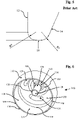
- a femoral resurfacing head prosthesis 10 in accordance with the state of the art is shown in Figures 1 to 5 and typically comprises a substantially spherical convex outer contact surface 12, a concave inner fixation surface 14, a rim 16 between the two surfaces defining an opening 18 and a stem 20 projecting from the concave inner fixation surface 14 and through the opening 18.
- metal-on-metal resurfacing can result in the production of metal ions and subsequent diffusion or transport of the metal ions to the bloodstream or locality surrounding the hip replacement prosthesis.
- the presence of metal ions can result in allergic reaction or other adverse health effects for the patient.
- the present invention which is defined in claim 1, seeks to provide a solution to these problems.
- ceramic is advantageous as the production of potentially hazardous metal ions is prevented or limited, given the reduction in the amount of metal used for the prosthesis. Additionally, ceramics are typically harder than most metals and therefore the wear of the prosthesis can be reduced compared to a typical arrangement, resulting in an increased longevity of the prosthesis. Hip resurfacing prostheses typically are not formed from ceramic as ceramics are generally brittle by nature and fracture can be unpredictable.
- a free distal end of the stem being at, or spaced inwardly of, the rim results in a shorter stem than in a typical or conventional metal resurfacing arrangement.
- a shorter stem results in a reduced moment acting about the base of the stem and/or at any given point along the stem. This therefore reduces the amount of stress acting at or adjacent to the base and therefore improves the stress characteristics at or adjacent the base.
- the improvement and/or relative lack of degradation of the stress characteristics at the base of the stem is key for the present invention given its formation from ceramic, rather than metal as is conventional, given that, in general, ceramic has a lower ductility than metal. The risk of mechanical failure of the stem, and thus of the entire prosthesis, is thus reduced.
- the prosthesis adopts a shape which substantially saves material.
- the device is therefore more conveniently and cheaply produced through green machining and sintering, a method typically used for the production of ceramic components.
- the shorter stem results in a shorter stem bore being required to be drilled for implantation and therefore improves bone conservation.
- a ceramic femoral resurfacing head prosthesis comprising: a ceramic convex outer contact surface engagable with an acetabulum of a patient or an acetabular cup prosthesis; a concave inner fixation surface, the ceramic convex outer contact surface and the concave inner fixation surface extending to intersect each other at a rim; and a ceramic stem projecting from the concave inner fixation surface and adapted to be received by a stem bore, wherein a free distal end of the stem is at, or spaced inwardly of, a plane defined by the said rim, wherein the ceramic stem includes at least a two-part angular transition in a longitudinal direction of the stem to meet the concave inner fixation surface such that an inner-land portion of the concave inner fixation surface at or adjacent to the ceramic stem is increased, the at least a two-part angular transition defining a curve in a longitudinal direction of the stem having a non-uniform radius
- the extension of the inner-land portion of the inner fixation surface increases an area of overlap between the inner fixation surface and the in use resected head of the femur, to which the ceramic femoral resurfacing head prosthesis is attached. This allows for an increase in an area of contact between in use bone cement or other bonding agent, typically applied between the prosthesis and the femur to adhere the prosthesis to the femur, and the inner fixation surface.
- An increase in the area of contact can increase the adhesion, and therefore the risk of failure of the resurfacing by detachment of the prosthesis from the femur is reduced. The longevity of the replacement may thus be increased.
- the concave inner fixation surface has a plurality of anti-rotation elements spaced around a circumference thereof.
- the at least two-part angular transition may define a curve in a longitudinal direction of the stem having a non-uniform radius.
- the at least two-part angular transition may include a first curved part having a radius in a range of 5mm to 150mm, a second curved part having a radius in a range of 10mm to 100mm, and a third curved part having a radius in a range of 0.5mm to 2mm.
- the first curved part may have a radius of or substantially of 50 mm
- the second curved part has a radius of or substantially of 17.5mm
- the third curved part has a radius of or substantially of 1.5mm.
- the first and second curved parts and the second and third curved parts are contiguous with each other.
- the at least two-part angular transition may include at least one flat in a longitudinal direction of the stem.
- the at least two-part angular transition is or includes a catenary curve.
- the concave inner fixation surface may include at least one circumferentially elongate recess for surgical bone cement interdigitation to prevent or inhibit pull-off removal of the head prosthesis.
- the circumferentially elongate recess may be an endless channel.
- the inner fixation surface may include a skirt between the inner-land portion and a rim of the head prosthesis, the circumferentially elongate recess being at the skirt.
- the outer contact surface and the inner fixation surface extend to intersect each other at a or the rim, and a free distal end of the stem is at or spaced inwardly of a plane defined by the said rim.
- a or the rim may define an asymmetrical profile between the inner fixation surface and the outer contact surface with two or more different arcs having a radius in a range of 0.2 mm to 1.5 mm.
- a or the rim may include at least an outer radius to the convex outer contact surface equal to or greater than 0.5 mm.
- the anti-rotation elements comprise one or more indentations on the inner fixation surface to receive a surgical bone cement.
- One or more of the anti-rotation elements may have the form of a discontinuous semi-toroidal indentation on the inner fixation surface.
- the anti-rotation elements may be equi-angularly spaced apart on the inner fixation surface.
- at least one anti-rotation element includes a multipart indentation having a plurality of anti-rotation zones. Each anti-rotation zone may be demarcated from the other anti-rotation zones by discontinuities in depth of the indentation at their respective boundary.
- each anti-rotation element has a central anti-rotation zone, and a plurality of non-central anti-rotation zones adjacent to the central anti-rotation zones.
- at least two non-central anti-rotation zones are separated from each other by the central anti-rotation zone.
- the central anti-rotation zone may comprise a majority of the volume of the indentation.
- the invention may be used in a method of increasing a fixation-land area of a ceramic femoral resurfacing head without or without substantially detrimentally affecting a stress characteristic at or adjacent to an associated stem, the method comprising the step of forming a stem of a ceramic femoral resurfacing head prosthesis with at least a two-part angular transition in a longitudinal direction thereof to meet an inner fixation surface.
- a two-part angular transition enables a first curved part to have a smaller or tighter radius of curvature, and a second curved part to have a greater radius of curvature, than the radius of curvature of the transition between the stem and the inner fixation surface for a typical or conventional femoral resurfacing head.
- a smaller radius of curvature allows for a sharper or more abrupt transition between the inner fixation surface and the longitudinal extent of the stem which enables an increase in the extent of the inner fixation surface.
- a second curved part having a greater bend radius reduces a stress concentration at the base of the stem. As such, the stress characteristic adjacent to the stem is not detrimentally affected, and the risk of mechanical failure of the stem is not increased compared to currently known transitions of metal resurfacing heads, given that the ceramic generally has a lower ductility compared to typical metal compositions.
- a radial extent of the at least two-part angular transition may be unbisectable.
- the at least two-part angular transition may be defined by two different curves.
- the at least two-part angular transition may be defined by a flat and a curve in a longitudinal direction of the stem.
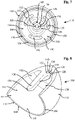
- a ceramic femoral resurfacing head prosthesis 110 comprising a ceramic convex outer contact surface 112, which is or is a substantially spherical surface and is generally a segment of a sphere slightly greater than a hemisphere, and a concave inner fixation surface 114.
- outer contact surface and the inner fixation surface are described as being convex and concave respectively, it is appreciated that one or both surfaces may in fact not be concave or convex and/or may be at least in part planar or multifaceted, as necessity dictates.
- the ceramic convex outer contact surface 112 and the concave inner fixation surface 114 are preferably contiguous and meet at a rim 116 which thereby forms a plane and a circular or substantially circular opening 118. In this way, the rim may be planar or substantially planar.
- a ceramic stem 120 projects from the concave inner fixation surface 114, preferably opposite or substantially opposite from the opening 118.
- the ceramic stem 120 may have a base portion 122 proximal to and at or adjacent to the concave inner fixation surface 114, a cylindrical or a substantially cylindrical shaped body portion 124 and a frustoconical or substantially frustoconical shaped distal free end 126, or tip portion, distal to the concave inner fixation surface 114 and the base portion 122, the body portion 124 separating the base portion 122 form the distal free end 126.
- a longitudinal extent of the ceramic stem 120 is such that the distal free end 126 is at or spaced inwardly of the plane defined by the rim 116.
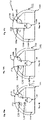
- the ceramic stem 120 is therefore shorter than the stem 20 of the prior art femoral resurfacing head prosthesis; a direct comparison of the two stems can be seen in Figures 15a to 15c and 16a to 16c . Whilst the extent of the ceramic stem is so described, it is appreciated that the longitudinal extent of the stem may be such that the distal free end of the stem extends beyond the plane defined by the rim.
- the base portion 122 of the ceramic stem 120 merges, substantially merges or transitions into the concave inner fixation surface 114 and the concave inner fixation surface 114 preferably has an inner-land 128 which here may be at or adjacent to base portion 122 such that it may be considered to extend around a circumferential extent of, surround, encircle and/or be adjacent to the base portion 122.
- the inner-land 128 is preferably planar or substantially planar and may be transverse, lateral or perpendicular or substantially perpendicular to a longitudinal extent of the ceramic stem 120. Whilst described as encircling the base portion, it is appreciated that the inner-land may only extend around part of the circumferential extent the base portion.
- an intermediary portion 130 of the concave inner fixation surface 114 may extend at an angle to the plane of the inner-land 128, and preferably at an obtuse angle. This arrangement is such that the intermediary portion 130 and the inner-land 128 together substantially form the shape of an external surface of a frustocone with a base removed.
- a plurality of, and preferably three as shown, anti-rotation elements 132 may be equiangularly arranged around a circumferential extent of the concave inner fixation surface 114, and more specifically the intermediary portion 130.
- Each anti-rotation element 132 may here be formed as an indentation, recess or groove in the concave inner fixation surface 114 and a longitudinal extent of the indentation, recess or groove may be aligned with a circumferential extent of the intermediary portion 130.
- the anti-rotation elements 132 are preferably spaced apart, i.e. discontinuous from one another, to prevent rotation around a circumferential extent of the concave inner fixation surface 114.
- each anti-rotation element 132 may be elongate and may have at least one rounded edge.
- Each of the anti-rotation elements 132 may have the form of a discontinuous semi-toroidal indentation. This toroidal indentation is such that a radial profile of the anti-rotation element 132 may be a circular or semi-circular.
- anti-rotation elements may take other forms, for example each anti-rotation element may be a circular recess or may be a projection.
- at least one of the anti-rotation elements may include a multipart indentation having a plurality of anti-rotation zones and each anti-rotation zone may be demarcated from the other anti-rotation zones by discontinuities in depth of the indentation at their respective boundary.
- Each anti-rotation element may have a central anti-rotation zone and a plurality of non-central anti-rotation zones adjacent to the central anti-rotation zone.
- the anti-rotation elements may in fact be positioned elsewhere on concave inner fixation surface, for example on the inner-land area 128. It is also appreciated that the ceramic femoral resurfacing head prosthesis may not necessarily include a or any anti-rotation elements.
- the concave inner fixation surface 114 may further comprise a skirt 134 positioned between the rim 116 and the inner-land 128, and more specifically between the rim 116 and the intermediary portion 130.
- the skirt 134 is preferably annular in shape and an axial extent of the annular shaped skirt 134 may extend parallel or substantially parallel to a longitudinal extent of the ceramic stem 120. Whilst described as extending parallel to the ceramic stem 120, it is appreciated that the axial extent of the skirt 134 may in fact extend at an angle and towards the stem and as such the skirt 134 may be considered to taper or narrow in diameter towards the rim 116.
- the axial extent of the skirt 134 may in fact extend at an angle and away from the stem such that the skirt 134 may be considered to widen in diameter towards the rim 116.
- the skirt 134 is preferably cylindrical or substantially cylindrical, or frusto-conical or substantially frusto-conical.
- the skirt 134 may preferably further comprise at least one circumferentially elongate recess 136 or groove in the concave inner fixation surface 114, preferably extending around a circumferential extent of the concave inner fixation surface 114 and/or skirt 134.
- the elongate recess 136 may be an endless channel, although it is appreciated that the recess may not be endless and may only extend around a portion of the extent of concave inner fixation surface. Additionally, there may be a plurality of circumferentially aligned and substantially coplanar elongate recesses 136 positioned in the skirt 134 which individually extend around a portion of the circumference of the skirt 134.
- the merging and/or transition of the base portion 122 of the ceramic stem 120 with or to the inner-land 128 of the concave inner fixation surface 114 is at least a two-part angular transition 138.
- Each part of the at least two-part angular transition 138 has a different radius or radius of curvature such that a radial extent of the at least two-part angular transition is unbisectable.
- the radius of curvature of each curved part is therefore different.
- the curved parts are not symmetrical about a plane which separates adjacent said curved parts.
- One or more of the curved parts are also not symmetrical about a line which bisects the said curved part.
- the unbisectability of the radial extent of the at least two-part angular transition 138 is shown by sectioning line B1 in Figure 9 , which does not bisect the two-part angular transition 138.
- the bisectability of the radial extent of the single angular transition 38 of the prior art is shown by bisection line B2 in Figure 4 .
- the at least two-part angular transition 138 defines a curve in an axial or longitudinal direction or extent of the stem 120 having a non-uniform radius.
- the at least two-part angular transition 138 is a three-part angular transition 140.
- the two- or three- part transition 138, 140 preferably extends uniformly around the circumferential extent of the base portion 122 of the ceramic stem 120. This is such that the base portion 122 of the stem 120 may be considered to be hyperbolic frustocone or a frustocone having a nonuniform pitch, with the wider base of the frustocone being adjacent to the inner-land 128.
- a direct comparison between the transition of the present invention and the transition 38 of the prior art can be seen in Figure 10 .
- the transition in accordance with the state of the art is also shown in Figures 3 and 4 .
- the three-part angular transition 140 preferably firstly comprises a first curved part 142.
- the first curved part 142 is an axial extent of the base portion 122 of the stem 120 being at or adjacent to the cylindrical body portion 124 having a constant, uniform or regular radius of curvature, referenced at R1 in Figure 10 .
- the curvature of R1 is preferably such that it curves away from an axial direction of the stem 120.
- the radius of curvature R1 is preferably in the range of 5 mm to 150 mm and more preferably may be at, around or substantially 50 mm.
- the first curved part may be flat, and thus have an undefinable radius of curvature, in an axial or longitudinal extent of the stem, or may be irregularly or non-uniformly curved. In the instance of being flat, an axial cross-section of the first curved part may be considered to be straight. Whilst the radius of curvature of the first part is given as preferably having an upper limit, it is appreciated that the radius of curvature may in fact only preferably be greater than 5 mm.
- the three-part angular transition 140 further comprises a second curved part 144.
- the second curved part 142 is on an axial extent of the base portion 122 of the stem 120 being adjacent to and contiguous with the first curved part 142 and is distal to the cylindrical body portion 124 as compared to the first curved part 142, having a radius of curvature referenced R2 in Figure 10 .
- the radius of curvature of the second curved part 144 may preferably be in the range of 10 mm to 100 mm, may more preferably be in the range of 10 mm to 25 mm, may most preferably be in the range of 15 mm to 20 mm, and may be at, around or substantially 17.5 mm.
- the second curved part 144 is described as being a curve having a radius of curvature of the above values, it is appreciated that the curve may in fact be a catenary curve thus having no singular radius of curvature.
- the second curved part may in fact be flat in an axial or longitudinal extent of the stem, and thus have an undefinable radius of curvature in an axial or longitudinal extent of the stem. In this instance, an axial cross-section of the second curved part may be considered to be straight.
- the second curved part may have parabolic character or have any irregular or non-uniform curvature. Whilst the radius of curvature of the second part is given as preferably having an upper limit, it is appreciated that the radius of curvature may in fact only preferably be greater than 10 mm.
- the three-part angular transition 140 lastly comprises a third curved part 146, having a radius of curvature labelled R3.
- the third curved part 146 is on and axial extent of the base portion 122 of the stem 120 being inter-positioned between and at or adjacent to both of the inner-land 128 portion and second curved part 144.
- the third curved part 146 may preferably have a constant, uniform or regular radius of curvature R3.
- the radius of curvature R3 of the third curved part 146 may preferably in the range of 0.5 mm to 2 mm, and more preferably may be at, around or substantially 1.5 mm.
- the third curved part may be flat, and thus have an undefinable radius of curvature in an axial or longitudinal extent of the stem or may be irregularly or non-uniformly curved.
- an axial cross-section of the third curved part may be considered to be straight.
- the radius of curvature of the third part is given as preferably having an upper limit, it is appreciated that the radius of curvature may in fact only preferably be greater than 0.5 mm.
- the at least two-part angular transition 138 is described as having three angular transitions, with the first and second curved parts 142, 144 being contiguous with each other and the second and third parts 144, 146 being contiguous with each other, it is appreciated that it may in fact only have two angular transitions or may have more than three angular transitions.
- the advantage provided by the at least two-part angular transition 138 is given by having at least two contiguous curved parts; a curved part adjacent to the stem and a curved part adjacent to the inner-land 128, the curved part adjacent to the inner-land 128 having a tighter or smaller radius of curvature than the radius of curvature of the curved part adjacent to the stem.
- the above values of radius of curvature R1, R2, R3 may vary and/or scale depending on the dimensions of the other features of the ceramic femoral resurfacing head prosthesis 110, particularly a diameter of the ceramic outer contact surface 112. Alternatively, the above values may not vary and/or scale depending on the dimensions of the ceramic of the other features of the ceramic femoral resurfacing head prosthesis 110.
- the transition may in fact not extend uniformly around the circumferential extent of the base and the number of curved parts or radius of curvature of each part of the transition may vary depending on its circumferential position. It is further noted that the ceramic femoral resurfacing head prosthesis 110 may in fact have a singular angular transition, for example, the curved part 38 in the state of the art having a radius of curvature of 2.5 mm and indicated by R4 in Figure 10 .
- the three-part angular transition 140 is so arranged to maximise the surface area of the inner-land 128, by decreasing the lateral extent over which the transition 140 extends, whilst maintaining, improving, or restricting or limiting a degradation of in use stress characteristics, such as stress concentration, adjacent to the base 124 of the ceramic stem 120 as compared to the prior art.
- This is achieved by having a third curved part 146 with a smaller radius of curvature than the radius of curvature R4 of the prior art, allowing the transition or merging between the stem 120 and the inner-land 128 to occur more proximal to the stem 120. Any negative affect to the stress characteristics by this tighter radius of curvature is mitigated by having second and/or first curved parts 142, 144 having a radius of curvature greater than the prior art and greater than the third curved part 146 which reduces stress concentration.
- the rim 116 preferably has an asymmetrical profile, the asymmetric profile may be considered to be a lateral profile of the rim 116.
- the asymmetrical profile of the rim 116, and a comparison to the symmetrical rim 116 of the prior art, may be seen in Figures 12 to 14 .
- the rim 116 here has an inner, or internal, edge 148 and an outer, or external, edge 150, both edges 148, 150 preferably extending around a circumferential extent of the rim 116 and thus the ceramic femoral resurfacing head prosthesis 110.
- the outer edge 150 may be proximal to the ceramic convex outer contact surface 112 and the inner edge 148 may be proximal to the concave inner fixation surface 114.
- Both the inner edge 148, and the outer edge 150 may be considered to be curved or substantially curved, the inner edge 148 having a radius of curvature labelled R5 in Figure 14 and similarly R6 for the outer edge 150.
- the radius of curvature of the inner edge 148 is preferably smaller than the radius of curvature of the outer edge 150.
- the radius of curvature of the inner edge 148 may preferably be in a range of 0.2 mm and 1.5 mm and may more preferably be at, around or substantially 0.5 mm.
- the radius of curvature of the outer edge 150 is preferably in the range of 0.5 mm and 2 mm, and more preferably being at, around or substantially 1 mm.
- the radius of curvature may vary depending on the overall size of the ceramic femoral resurfacing head prosthesis 110 and that the importance of this part of the present invention is that the radius of curvature of the outer edge 150 is greater than the radius of curvature of the inner edge 148.
- a substantially flat or planar portion may interspace the inner and outer edges 148, 150.
- the effect of the lateral profile of the rim 116 being asymmetrical is that the rim 116 may be thickened, when compared to the prior art, by the axial extent of the ceramic femoral resurfacing head prosthesis 110 being reduced, but the concave inner fixation surface 114 may still be maximised.
- the smaller inner radius of curvature R5 maximises the concave inner fixation surface 114 by reducing the axial extent of the transition between the inner surface 114 and the distal surface of the rim 116.
- the larger outer radius of curvature R6 reduces stress concentration and therefore reduces the risk of fracture or failure of part of this component, when compared to a smaller or typical radius of curvature.
- the profile of the rim 116 of the ceramic femoral resurfacing head prosthesis 110 is here described as being asymmetrical, it is appreciated that it may in fact be symmetrical, for example similar to or the same as the profile of the rim 16 in the prior art.
- the ceramic femoral resurfacing head prosthesis 110 may preferably be wholly made from ceramic; however, it is appreciated that ceramic femoral resurfacing head prosthesis may only partly be made from ceramic and that selected components, such as the stem 120, may not be made from ceramic.
- the ceramic selected for use in the ceramic femoral resurfacing head prosthesis 110 may preferably be inert to the human body and should have a high hardness to reduce wear. Ceramics suitable for use may in particular be zirconia toughened alumina but also alumina, zirconia, activated alumina, bioglass, silicon nitride, zirconia or any other ceramic.
- the rim 116 Whilst the rim 116 is here described as forming a plane it is appreciated that the rim 116 may not be substantially planar and may undulate, for example having the form of a wave or having a sinusoidal or substantially sinusoidal circumferential extent. In the event that the rim 116 is not planar, a plane defined by the rim 116 may be taken to be the extent of the rim 116 furthest from, closest to or at a mean distance of the rim from the inner-land portion 120. Additionally or alternatively, whilst the plane defined by the rim 116 is shown as being perpendicular to the longitudinal extent of the ceramic stem 120, it is appreciated that the rim may not perpendicular to the longitudinal extent of the ceramic stem 120. For example, the plane defined by the rim may be at an angle to the ceramic stem 120, due to an asymmetrical longitudinal extent of the skirt 134.
- FIGS 15a to 15c there are shown variations of the first embodiment of the ceramic femoral resurfacing head prosthesis 110 together forming a first group 152 of ceramic femoral resurfacing head prostheses 110.
- FIGs 16a to 16c there are shown variations of the first embodiment of the ceramic femoral resurfacing head prosthesis 110 together forming a second group 154 of ceramic femoral resurfacing head prostheses 110.
- first and second groups 152, 154 are described, it will be clear that more than two groups having the characteristics outlined hereinafter can be provided, where necessity dictates.
- Each prosthesis variation of the first embodiment may be at least in part distinguished by a differing equatorial diameter of the convex outer contact surface 112 for each ceramic femoral resurfacing head prosthesis 110.
- the equatorial diameter of the convex outer contact surface 112 in mm for each variation of first embodiment is given below each figure as a size.
- Size 40 refers to an equatorial diameter of substantially 40 mm.
- a lateral extent of the ceramic stem 120i may be constant, common or uniform or substantially constant, common or uniform along at least a majority of a longitudinal extent of the stem.
- the said lateral extent which is constant across the group may be taken from a same or similar longitudinal reference point for each ceramic stem 120i of a first group 152.
- the longitudinal reference point may, for example, be within a longitudinal extent of the body portion 124i, the body portion of each ceramic stem preferably having a constant or substantially constant lateral extent therealong. Alternatively, the longitudinal reference point may be taken to be at the base of the ceramic stem 120i or between the inner-land 128i and the body portion 124i.
- each ceramic stem 120i within the first group 152 may at least be along part of the longitudinal extent of each ceramic stem 120i and may preferably be constant or substantially constant along a majority of each ceramic stem 120i of a group. Whilst a lateral extent of each ceramic stem 120i is constant, a longitudinal extent of each stem 120i may vary across the group 152. This varying longitudinal extent may be achieved by varying only the longitudinal extent of the body portion 124i of each stem 120i, in this way a longitudinal and lateral extent of the base portion 122i and the distal free end portion 126i of each stem within the group 152 may be constant or common.
- the length of the ceramic stem may be varied by also or only varying the longitudinal extent of the base portion 122i, including the at least two-part angular transition 138i, and/or the distal free end portion 126i. Given the non-constant lateral extent of the base portion 122i or distal free end portion 126i, by varying their longitudinal extent the lateral extent of the ceramic stem 120i may vary at these portions and thus the lateral extent of each ceramic stem 120i within a group may not be constant along the entirety of the longitudinal extent of the stem 120i. In the event that a lateral cross-section of the ceramic stem 120i is not circular, the major or largest lateral dimension of the lateral extent should be constant, common or uniform across a group, in the same or similar way as described above.
- the at least two-part angular transition 138i may be the same for each ceramic stem 120i of each ceramic femoral resurfacing head prosthesis 110i within the first group 152.
- the at least two-part angular transition 138i may be different for each ceramic stem 120i of each ceramic femoral resurfacing head prosthesis 110i within the first group 152. This difference may be due to differing radii of curvature for each or any of the curved parts of the two-part angular transition 138 across each femoral resurfacing head prosthesis 110i of the first group 152.
- each ceramic stem 120i is described as varying across a first group 152, it is appreciated that the longitudinal extent of each ceramic stem 120i may also remain constant, common or uniform or substantially constant, common or uniform.
- the lateral extent of the ceramic stem 120i may be in the range of 5 mm to 7.5 mm, and more preferably may be at, around or substantially 6.6 mm.
- the lateral extent of the first group 152 may be given by ⁇ X in Figures 15a to 15c .
- the dimensions of the remainder of the features of each of the femoral resurfacing head prosthesis may vary, especially the ceramic convex outer contact surface 112i, the concave inner fixation surface 114i and even a length of the stem.
- each ceramic femoral resurfacing head prosthesis 110i may have a different equatorial circumference to that of the other ceramic femoral resurfacing head prostheses 110i of the first group 152. Therefore, the ceramic stems of all of the ceramic femoral resurfacing head prostheses 110i of a first group 152 may be individually selectively co-operable with a given, and the same, stem bore, also known as the femoral bore.
- the lateral extent of the ceramic stem 120iv may be constant, common or uniform or substantially constant, common or uniform along at least part of the longitudinal extent of the ceramic stem.
- the said constant lateral extent may be taken at the same or similar longitudinal reference point as above.
- the longitudinal extent of each of the ceramic stems 120iv within the group 154 may vary or, alternatively, may not vary.
- the lateral extent of ceramic stem 120iv may be in the range of 7 mm to 9 mm, and more preferably may be at, around or substantially 8.1 mm and therefore may be generally greater than the lateral extent of the ceramic stem 120i of the first group 152.
- the lateral extent of the second group 154 is given by ⁇ Y in Figures 16a to 16c .
- the dimensions of the remainder of the features of each of the femoral resurfacing head prosthesis may vary, especially the convex outer contact surface.
- the dimensions of said features of the second group 154, including the longitudinal extent of the stem 120iv, may also vary with respect to the dimensions of the said features of the first group 152.
- each ceramic femoral resurfacing head prosthesis 110iv may have a different equatorial circumference and/or a different longitudinal extent of the stem, to that of the other ceramic femoral resurfacing head prosthesis 110iv of a second group 154 and of the first group 152.
- the at least two-part angular transition 138i of the ceramic stem 120i of the first group 152 may be the same or similar to the at least two-part angular transition 138iv of the ceramic stem 120iv of the second group 154.
- the at least two-part angular transition 138i of the ceramic stem 120i of the first group 152 may be different to the at least two-part angular transition 138iv of the ceramic stem 120iv of the second group 154.
- the lateral extent of the ceramic stem 120iv of the second group 154 is different to the ceramic stem 120i of the first group 152. Therefore, the ceramic stems of all of the ceramic femoral resurfacing head prostheses 110iv of a second group 154 may be individually selectively co-operable with a given, and the same, stem or femoral bore, but may not be individually selectively co-operable with a stem or femoral bore suitable for use with the first group 152 and vice versa.
- a range of prostheses having differing ceramic convex outer contact surfaces 112 and concave inner fixation surface 114, but all being suitable for insertion into a stem bore or femoral bore of the same dimensions, and in particular the same lateral dimension, may be selectable.
- the only difference between the ceramic femoral resurfacing head prostheses 110 are the relative size of the lateral extent of the stem 120 compared to the other features, it is appreciated that within a group, for a given lateral extent of stem, there may be other variations. For example, there may be differing numbers of anti-rotation elements or no anti-rotation elements between the ceramic femoral resurfacing head prostheses of a group. Additionally, there may be more or different shaped or sized elongate recesses to promote adhesion to the head of the femur. Therefore, in use the surgeon may select from a group of femoral resurfacing head prostheses having a particular feature and having already prepared the stem bore during surgery.
- a surgical procedure may be performed to in use apply the ceramic femoral resurfacing head prosthesis 110 to a patient. This may take the form of making an incision in the patient, adjacent to the hip. The surgical approach may be most commonly made posterior to the hip, however lateral, anterior, anterior-lateral and medial approaches are also possible. The head portion of the femur and the acetabulum are then exposed and the head of the femur may be dislocated from the acetabulum.
- a ceramic femoral resurfacing head prosthesis 110 or femoral resurfacing head prosthesis group 152, 154 may be selected based on the size of the femur head and the size of the acetabulum or acetabular cup into which the femur is to be inserted.
- the head of the femur is then prepared and/or resected by shaping the femur so as to substantially correspond with the concave inner fixation surface 114 of the selected femoral resurfacing head prosthesis. This may involve removing an edge portion of the head of the femur using a chamfer-cutting tool.
- a stem bore may be drilled into a longitudinal extent of the femur, the diameter and length of the bore to be drilled corresponding to the dimensions of the stem 120 of the femoral resurfacing head prosthesis 110 or femoral resurfacing head prosthesis group 152, 154 selected. If a group 152, 154 of femoral resurfacing head prostheses 110 has been selected then a single femoral resurfacing head prosthesis 110 is selected from that group which corresponds most closely with the size of the acetabulum or acetabular cup into which the resurfaced femur head is to be inserted.
- Bone cement is then applied to the concave inner fixation surface 114 and/or the surface of the resected femur.
- the femoral resurfacing head prosthesis is then positioned over the resected femur and the ceramic stem 120 is inserted into the stem bore.
- the bone cement bonds or affixes the resected femur to the ceramic femoral head prosthesis.
- the optional anti-rotation elements 132 may be filled with cement and therefore prevent rotation of the femoral resurfacing head prosthesis.
- the elongate recess 136 may also be filled with cement and thereby promote surgical bone cement interdigitation to prevent or inhibit pull-off removal of the head prosthesis 110.
- the resurfaced ceramic femoral head may then be inserted or impacted into the acetabulum or acetabular cup.
- the acetabulum is then typically prepared to receive an in use acetabular cup by removing cartilage from and otherwise enlarging the acetabulum with a reamer.
- An in use acetabular cup selected to correspond to the ceramic convex outer contact surface, is then inserted or impacted into the enlarged acetabulum and may be secured by using an adhesive such as bone cement.
- the area around the hip may then be cleaned to remove any excess bone or cement, and the incision may be sealed.
- the above procedure may be performed in a reverse sequence and the above sequence of events is given for illustrative purposes only.
- the procedure may clearly also be performed by first preparing the acetabulum or acetabular cup and then resurfacing the femoral head.
- a ceramic femoral head prosthesis which, through a two- or more-part angular transition of the stem to increase an inner-land for improved bone engagement and support, has at least comparable stress characteristics at or adjacent to a base of the stem compared to presently known non-ceramic femoral head prostheses.
- each group having a common ceramic stem dimension, profile or stem diameter By each group having a common ceramic stem dimension, profile or stem diameter, a number of tools required to fit the selected prosthesis may be reduced.
Landscapes
- Health & Medical Sciences (AREA)
- Orthopedic Medicine & Surgery (AREA)
- Transplantation (AREA)
- Vascular Medicine (AREA)
- Oral & Maxillofacial Surgery (AREA)
- Engineering & Computer Science (AREA)
- Biomedical Technology (AREA)
- Heart & Thoracic Surgery (AREA)
- Cardiology (AREA)
- Life Sciences & Earth Sciences (AREA)
- Animal Behavior & Ethology (AREA)
- General Health & Medical Sciences (AREA)
- Public Health (AREA)
- Veterinary Medicine (AREA)
- Physical Education & Sports Medicine (AREA)
- Prostheses (AREA)
Claims (12)
- Keramische Femurkopfkappenprothese (110), umfassend:eine keramische konvexe äußere Kontaktfläche (112), die mit einem Acetabulum eines Patienten oder einer Acetabulumpfannenprothese in Eingriff gebracht werden kann; undeine konkave innere Befestigungsfläche (114), wobei die keramische konvexe äußere Kontaktfläche (112) und die konkave innere Befestigungsfläche (114) sich erstrecken, um einander an einem Rand (116) zu kreuzen;dadurch gekennzeichnet, dass die keramische Femurkopfkappenprothese (110) weiterhin einen keramischen Schaft (120) umfasst, der von der konkaven inneren Befestigungsfläche (114) vorragt und dazu eingerichtet ist, von einer Schaftbohrung aufgenommen zu werden, wobei ein freies distales Ende (126) des Schafts (120) an einer Ebene, die von dem Rand (116) definiert wird, ist oder von dieser nach innen beabstandet ist, wobeider keramische Schaft (120) mindestens einen zweiteiligen abgewinkelten Übergang (138) in einer Längsrichtung des Schafts (120) beinhaltet, um mit der konkaven inneren Befestigungsfläche (114) zusammenzutreffen, so dass ein Innenflächenabschnitt (128) der konkaven inneren Befestigungsfläche (114) an oder angrenzend an dem keramischen Schaft (120) vergrößert wird, wobei der mindestens eine zweiteilige abgewinkelte Übergang (138) eine Kurve in einer Längsrichtung des Schafts (120) mit einem uneinheitlichen Radius definiert.
- Keramische Femurkopfkappenprothese (110) nach Anspruch 1, wobei die konkave innere Befestigungsfläche (114) mehrere Antirotationselemente (132) aufweist, die um einen Umfang davon beabstandet sind.
- Keramische Femurkopfkappenprothese (110) nach Anspruch 2, wobei eines oder mehr der mehreren Antirotationselemente (132) die Form einer unterbrochenen Einkerbung, unterbrochenen Aussparung und/oder unterbrochenen Nut aufweist bzw. aufweisen.
- Keramische Femurkopfkappenprothese (110) nach einem der vorhergehenden Ansprüche, wobei der mindestens eine zweiteilige abgewinkelte Übergang (138) einen ersten gewölbten Teil (142) mit einem Radius in einem Bereich von 5 mm bis 150 mm, einen zweiten gewölbten Teil mit einem Radius in einem Bereich von 10 mm bis 100 mm und einen dritten gewölbten Teil (146) mit einem Radius in einem Bereich von 0,5 mm bis 2 mm beinhaltet.
- Keramische Femurkopfkappenprothese (110) nach Anspruch 4, wobei der erste und der zweite gewölbte Teil (142) und der zweite und der dritte gewölbte Teil (146) miteinander zusammenhängend sind.
- Keramische Femurkopfkappenprothese (110) nach einem der vorhergehenden Ansprüche, wobei der mindestens eine zweiteilige abgewinkelte Übergang (138) mindestens eine Abflachung in einer Längsrichtung des Schafts (120) beinhaltet.
- Keramische Femurkopfkappenprothese (110) nach einem der vorhergehenden Ansprüche, wobei der mindestens eine zweiteilige abgewinkelte Übergang (138) eine Kettenlinie ist oder beinhaltet.
- Keramische Femurkopfkappenprothese (110) nach einem der vorhergehenden Ansprüche, wobei die innere Befestigungsfläche (114) eine Schürze (134) zwischen dem Innenflächenabschnitt (128) und dem Rand (116) beinhaltet.
- Keramische Femurkopfkappenprothese (110) nach einem der vorhergehenden Ansprüche, wobei die innere Befestigungsfläche (114) mindestens eine umfänglich längliche Aussparung (136) an der Schürze (134) beinhaltet, um eine Abzugsentfernung der Kopfprothese (110) zu verhindern oder zu hemmen.
- Keramische Femurkopfkappenprothese (110) nach Anspruch 9, wobei die umfänglich längliche Aussparung (136) ein endloser Kanal ist.
- Keramische Femurkopfkappenprothese (110) nach einem der Ansprüche 8 bis 10, wobei die Schürze (134) vorzugsweise zylindrisch oder im Wesentlichen zylindrisch oder kegelstumpfförmig oder im Wesentlichen kegelstumpfförmig ist.
- Keramische Femurkopfkappenprothese (110) nach einem der vorhergehenden Ansprüche, wobei der Rand (116) der keramischen Femurkopfkappenprothese (110) ein asymmetrisches Profil zwischen der inneren Befestigungsfläche (114) und der äußeren Kontaktfläche (112) mit zwei oder mehr unterschiedlichen Bögen mit einem Radius in einem Bereich von 0,2 mm bis 1,5 mm definiert.
Priority Applications (3)
| Application Number | Priority Date | Filing Date | Title |
|---|---|---|---|
| EP22189014.8A EP4218683B1 (de) | 2017-11-01 | 2018-11-01 | Verbesserungen an oder im zusammenhang mit der oberflächenerneuerung einer keramischen femurkopfprothese |
| EP22182910.4A EP4088692B1 (de) | 2017-11-01 | 2018-11-01 | Verbesserungen an oder im zusammenhang mit der oberflächenerneuerung einer keramischen femurkopfprothese |
| EP22183281.9A EP4212132B1 (de) | 2017-11-01 | 2018-11-01 | Verbesserungen an oder im zusammenhang mit der oberflächenerneuerung einer keramischen femurkopfprothese |
Applications Claiming Priority (2)
| Application Number | Priority Date | Filing Date | Title |
|---|---|---|---|
| GB1718082.9A GB2568047B (en) | 2017-11-01 | 2017-11-01 | Improvements in or relating to ceramic femoral resurfacing head prosthesis |
| PCT/GB2018/053182 WO2019086889A1 (en) | 2017-11-01 | 2018-11-01 | Improvements in or relating to ceramic femoral resurfacing head prosthesis |
Related Child Applications (5)
| Application Number | Title | Priority Date | Filing Date |
|---|---|---|---|
| EP22182910.4A Division EP4088692B1 (de) | 2017-11-01 | 2018-11-01 | Verbesserungen an oder im zusammenhang mit der oberflächenerneuerung einer keramischen femurkopfprothese |
| EP22182910.4A Division-Into EP4088692B1 (de) | 2017-11-01 | 2018-11-01 | Verbesserungen an oder im zusammenhang mit der oberflächenerneuerung einer keramischen femurkopfprothese |
| EP22183281.9A Division EP4212132B1 (de) | 2017-11-01 | 2018-11-01 | Verbesserungen an oder im zusammenhang mit der oberflächenerneuerung einer keramischen femurkopfprothese |
| EP22183281.9A Division-Into EP4212132B1 (de) | 2017-11-01 | 2018-11-01 | Verbesserungen an oder im zusammenhang mit der oberflächenerneuerung einer keramischen femurkopfprothese |
| EP22189014.8A Division EP4218683B1 (de) | 2017-11-01 | 2018-11-01 | Verbesserungen an oder im zusammenhang mit der oberflächenerneuerung einer keramischen femurkopfprothese |
Publications (2)
| Publication Number | Publication Date |
|---|---|
| EP3678601A1 EP3678601A1 (de) | 2020-07-15 |
| EP3678601B1 true EP3678601B1 (de) | 2022-08-10 |
Family
ID=60580316
Family Applications (4)
| Application Number | Title | Priority Date | Filing Date |
|---|---|---|---|
| EP22189014.8A Active EP4218683B1 (de) | 2017-11-01 | 2018-11-01 | Verbesserungen an oder im zusammenhang mit der oberflächenerneuerung einer keramischen femurkopfprothese |
| EP18811891.3A Active EP3678601B1 (de) | 2017-11-01 | 2018-11-01 | Verbesserungen an oder im zusammenhang mit der oberflächenerneuerung einer keramischen femurkopfprothese |
| EP22182910.4A Active EP4088692B1 (de) | 2017-11-01 | 2018-11-01 | Verbesserungen an oder im zusammenhang mit der oberflächenerneuerung einer keramischen femurkopfprothese |
| EP22183281.9A Active EP4212132B1 (de) | 2017-11-01 | 2018-11-01 | Verbesserungen an oder im zusammenhang mit der oberflächenerneuerung einer keramischen femurkopfprothese |
Family Applications Before (1)
| Application Number | Title | Priority Date | Filing Date |
|---|---|---|---|
| EP22189014.8A Active EP4218683B1 (de) | 2017-11-01 | 2018-11-01 | Verbesserungen an oder im zusammenhang mit der oberflächenerneuerung einer keramischen femurkopfprothese |
Family Applications After (2)
| Application Number | Title | Priority Date | Filing Date |
|---|---|---|---|
| EP22182910.4A Active EP4088692B1 (de) | 2017-11-01 | 2018-11-01 | Verbesserungen an oder im zusammenhang mit der oberflächenerneuerung einer keramischen femurkopfprothese |
| EP22183281.9A Active EP4212132B1 (de) | 2017-11-01 | 2018-11-01 | Verbesserungen an oder im zusammenhang mit der oberflächenerneuerung einer keramischen femurkopfprothese |
Country Status (7)
| Country | Link |
|---|---|
| US (1) | US11278414B2 (de) |
| EP (4) | EP4218683B1 (de) |
| AU (3) | AU2018361710B2 (de) |
| ES (3) | ES3034245T3 (de) |
| GB (3) | GB2570070B (de) |
| PL (1) | PL4088692T3 (de) |
| WO (1) | WO2019086889A1 (de) |
Families Citing this family (6)
| Publication number | Priority date | Publication date | Assignee | Title |
|---|---|---|---|---|
| US12458500B2 (en) * | 2017-11-01 | 2025-11-04 | Matortho Limited | Ceramic femoral resurfacing head prosthesis |
| GB2570070B (en) * | 2017-11-01 | 2020-02-26 | Matortho Ltd | Improvements in or relating to ceramic femoral resurfacing head prosthesis |
| EP3607913B1 (de) * | 2018-08-10 | 2021-07-07 | Mathys AG Bettlach | Femurkappenimplantat für hüftoberflächenersatz |
| GB2585397B (en) * | 2019-11-28 | 2021-09-01 | Matortho Ltd | Ceramic monobloc femoral component, kit and system comprising the same, and method of manufacture and use thereof |
| EP4166114B1 (de) | 2021-10-15 | 2024-04-17 | FX Shoulder Solutions | Implantat mit keramischer gelenkfläche |
| CN119097478A (zh) * | 2024-09-13 | 2024-12-10 | 苏州中科生物医用材料有限公司 | 一种股骨部件及表面髋关节置换假体 |
Citations (1)
| Publication number | Priority date | Publication date | Assignee | Title |
|---|---|---|---|---|
| US4312079A (en) * | 1979-04-11 | 1982-01-26 | Feldmuhle Aktiengesellschaft | Femur head cap for endoprosthesis |
Family Cites Families (37)
| Publication number | Priority date | Publication date | Assignee | Title |
|---|---|---|---|---|
| CH612585A5 (de) * | 1977-05-23 | 1979-08-15 | Sulzer Ag | |
| DE2751537A1 (de) * | 1977-11-18 | 1979-05-23 | Wolfgang Bongartz | Hueftgelenkprothese |
| CA1227601A (en) * | 1983-05-06 | 1987-10-06 | Frederick F. Buechel | Prosthesis with interlocking fixation and providing reduction of stress shielding |
| US4752296A (en) * | 1983-05-06 | 1988-06-21 | Buechel Frederick F | Prosthesis with interlocking fixation and providing reduction of stress shielding |
| FR2686503B1 (fr) * | 1992-01-23 | 1995-11-24 | Tornier Sa | Prothese de rehabilitation de la tete femorale. |
| US6540786B2 (en) * | 1995-08-23 | 2003-04-01 | Jean Chibrac | Joint prosthesis members and method for making same |
| US6063124A (en) * | 1999-03-01 | 2000-05-16 | Amstutz; Harlan C. | Acetabular cup prosthesis insertion and removal assembly and technique |
| US20060085080A1 (en) * | 2002-10-11 | 2006-04-20 | Cartificial A/S | Medical device comprising a bio-compatible polymeric product with a layered structure |
| GB2396561A (en) * | 2002-12-27 | 2004-06-30 | Biomet Merck Ltd | Hip prosthesis with ceramic bearing |
| US7338498B2 (en) * | 2003-03-31 | 2008-03-04 | Depuy Products, Inc. | Prosthetic implant, trial and associated method |
| US8105327B2 (en) * | 2003-03-31 | 2012-01-31 | Depuy Products, Inc. | Punch, implant and associated method |
| EP1566154A1 (de) * | 2004-02-20 | 2005-08-24 | Argomedical AG | Prothese zum Oberflächenersatz im Bereich der Kugel von Kugelgelenken |
| KR100607401B1 (ko) * | 2004-05-13 | 2006-08-02 | 박형배 | 혈관보존형 대퇴골두 표면치환기구 |
| US20080033577A1 (en) * | 2004-07-01 | 2008-02-07 | Lawrence Kohan | Hip Resurfacing Component |
| US7361194B2 (en) * | 2004-10-14 | 2008-04-22 | Wright Medical Technology, Inc. | Metallic bearings for joint replacement |
| AU2006200043B2 (en) * | 2005-01-07 | 2011-11-17 | Inframat Corporation | Coated medical devices and methods of making and using |
| CA2621019A1 (en) | 2005-08-31 | 2007-03-08 | Zimmer Gmbh | Implant |
| GB2434749A (en) | 2006-02-06 | 2007-08-08 | Hip Dynamics Ltd | Hip prosthesis |
| FR2898267B1 (fr) * | 2006-03-10 | 2008-12-26 | Michel Timoteo | Implant de re-surfacage de tete femorale et son ancillaire. |
| EP2108338A3 (de) * | 2006-09-15 | 2010-03-17 | Corin Limited | Oberflächenumformung-Femurkopfteil |
| GB0618930D0 (en) * | 2006-09-26 | 2006-11-08 | Smith & Nephew | Medical implant |
| DE102007032583B3 (de) * | 2007-07-09 | 2008-09-18 | Eska Implants Gmbh & Co.Kg | Set zur Erstellung eines Offset-Resurfacing-Hüftgelenksimplantates |
| DE102007041794B3 (de) * | 2007-08-30 | 2009-04-30 | Eska Implants Gmbh & Co.Kg | Set zur Erstellung eines Offset-Resurfacing-Gelenkkopf-Kappenimplantates für ein künstliches Hüftgelenk |
| WO2009076293A2 (en) * | 2007-12-10 | 2009-06-18 | Mako Surgical Corp. | Prosthetic device and method for implanting the prosthetic device |
| EP2231072B1 (de) * | 2007-12-10 | 2019-05-22 | Mako Surgical Corp. | Prothesenvorrichtung und system zur vorbereitung eines knochens für die aufnahme einer prothesenvorrichtung |
| GB0803679D0 (en) * | 2008-02-28 | 2008-04-09 | Finsbury Dev Ltd | Prosthesis |
| ITMI20081367A1 (it) * | 2008-07-25 | 2010-01-26 | Alessandro Vio | "protesi coxo-femorale di superficie per cani" |
| GB0820233D0 (en) * | 2008-11-05 | 2008-12-10 | Smith & Nephew | Medical device |
| GB201006527D0 (en) * | 2010-04-19 | 2010-06-02 | Mcminn Derek J W | Femoral implant |
| FR2996443B1 (fr) * | 2012-10-10 | 2015-10-30 | Philippe Valenti | Cupule de resurfacage pour une tete d’un os long |
| MX356234B (es) | 2012-10-12 | 2018-05-14 | Univ Autonoma De Nuevo Leon | Prótesis total de cadera de superficie con mayor rango de movimiento y amortiguamiento hueso-implante. |
| CA2894769C (en) * | 2012-12-18 | 2021-06-15 | Bispebjerg Hospital | Medical implant for reducing pain in diseased joints |
| US20160045320A1 (en) * | 2014-08-18 | 2016-02-18 | RevOrtho LLC | Variable hip resurfacing femoral implant |
| GB2531589B (en) * | 2014-10-23 | 2017-02-01 | James Wallace Mcminn Derek | Femoral head resurfacing implant |
| GB201519629D0 (en) * | 2015-11-06 | 2015-12-23 | Embody Orthopaedic Ltd | Holder for resurfacing head implant |
| GB2570070B (en) * | 2017-11-01 | 2020-02-26 | Matortho Ltd | Improvements in or relating to ceramic femoral resurfacing head prosthesis |
| EP3777775A1 (de) * | 2019-08-13 | 2021-02-17 | Alessandro Melozzi | Oberschenkelknochenflächenersatzprothese |
-
2017
- 2017-11-01 GB GB1905809.8A patent/GB2570070B/en active Active
- 2017-11-01 GB GB1718082.9A patent/GB2568047B/en active Active
- 2017-11-01 GB GB1802167.5A patent/GB2554844B/en active Active
-
2018
- 2018-11-01 PL PL22182910.4T patent/PL4088692T3/pl unknown
- 2018-11-01 EP EP22189014.8A patent/EP4218683B1/de active Active
- 2018-11-01 ES ES22182910T patent/ES3034245T3/es active Active
- 2018-11-01 US US16/759,406 patent/US11278414B2/en active Active
- 2018-11-01 EP EP18811891.3A patent/EP3678601B1/de active Active
- 2018-11-01 AU AU2018361710A patent/AU2018361710B2/en active Active
- 2018-11-01 ES ES22183281T patent/ES3063646T3/es active Active
- 2018-11-01 EP EP22182910.4A patent/EP4088692B1/de active Active
- 2018-11-01 WO PCT/GB2018/053182 patent/WO2019086889A1/en not_active Ceased
- 2018-11-01 EP EP22183281.9A patent/EP4212132B1/de active Active
- 2018-11-01 ES ES18811891T patent/ES2929370T3/es active Active
-
2024
- 2024-06-04 AU AU2024203758A patent/AU2024203758B2/en active Active
-
2025
- 2025-09-12 AU AU2025230779A patent/AU2025230779A1/en active Pending
Patent Citations (1)
| Publication number | Priority date | Publication date | Assignee | Title |
|---|---|---|---|---|
| US4312079A (en) * | 1979-04-11 | 1982-01-26 | Feldmuhle Aktiengesellschaft | Femur head cap for endoprosthesis |
Also Published As
| Publication number | Publication date |
|---|---|
| US11278414B2 (en) | 2022-03-22 |
| EP4088692C0 (de) | 2025-05-07 |
| EP4212132B1 (de) | 2026-01-21 |
| GB2568047B (en) | 2021-10-27 |
| EP4212132A3 (de) | 2023-09-27 |
| US20200323639A1 (en) | 2020-10-15 |
| AU2024203758B2 (en) | 2025-06-26 |
| EP4212132C0 (de) | 2026-01-21 |
| GB2568047A (en) | 2019-05-08 |
| AU2024203758A1 (en) | 2024-06-20 |
| GB2570070B (en) | 2020-02-26 |
| EP3678601A1 (de) | 2020-07-15 |
| WO2019086889A1 (en) | 2019-05-09 |
| GB2570070A (en) | 2019-07-10 |
| GB201718082D0 (en) | 2017-12-13 |
| EP4088692A1 (de) | 2022-11-16 |
| AU2018361710B2 (en) | 2024-03-28 |
| AU2025230779A1 (en) | 2025-10-02 |
| EP4088692B1 (de) | 2025-05-07 |
| ES2929370T3 (es) | 2022-11-28 |
| EP4218683B1 (de) | 2026-05-06 |
| GB2554844A (en) | 2018-04-11 |
| ES3063646T3 (en) | 2026-04-17 |
| GB2554844B (en) | 2019-01-30 |
| EP4212132A2 (de) | 2023-07-19 |
| GB201905809D0 (en) | 2019-06-05 |
| PL4088692T3 (pl) | 2025-09-15 |
| ES3034245T3 (en) | 2025-08-14 |
| EP4218683A1 (de) | 2023-08-02 |
| GB201802167D0 (en) | 2018-03-28 |
| AU2018361710A1 (en) | 2020-06-11 |
Similar Documents
| Publication | Publication Date | Title |
|---|---|---|
| EP4088692B1 (de) | Verbesserungen an oder im zusammenhang mit der oberflächenerneuerung einer keramischen femurkopfprothese | |
| CA2588523C (en) | Femoral head resurfacing | |
| CN101277651B (zh) | 移植器 | |
| EP2561832A1 (de) | Prothese | |
| EP1858452B1 (de) | Lange manschetten zur verwendung mit schäften | |
| US20080262626A1 (en) | Femoral sleeve for hip resurfacing | |
| US12396856B2 (en) | Ceramic femoral resurfacing head prosthesis | |
| GB2593127A (en) | Improvements in or relating to ceramic femoral resurfacing head prosthesis | |
| GB2571650A (en) | Improvements in or relating to ceramic femoral resurfacing head prosthesis | |
| AU2021366372B2 (en) | Prostheses | |
| HK40096333A (zh) | 假体 | |
| GB2630902A (en) | Prostheses | |
| GB2551155A (en) | Prosthesis |
Legal Events
| Date | Code | Title | Description |
|---|---|---|---|
| STAA | Information on the status of an ep patent application or granted ep patent |
Free format text: STATUS: UNKNOWN |
|
| STAA | Information on the status of an ep patent application or granted ep patent |
Free format text: STATUS: THE INTERNATIONAL PUBLICATION HAS BEEN MADE |
|
| PUAI | Public reference made under article 153(3) epc to a published international application that has entered the european phase |
Free format text: ORIGINAL CODE: 0009012 |
|
| STAA | Information on the status of an ep patent application or granted ep patent |
Free format text: STATUS: REQUEST FOR EXAMINATION WAS MADE |
|
| 17P | Request for examination filed |
Effective date: 20200324 |
|
| AK | Designated contracting states |
Kind code of ref document: A1 Designated state(s): AL AT BE BG CH CY CZ DE DK EE ES FI FR GB GR HR HU IE IS IT LI LT LU LV MC MK MT NL NO PL PT RO RS SE SI SK SM TR |
|
| AX | Request for extension of the european patent |
Extension state: BA ME |
|
| DAV | Request for validation of the european patent (deleted) | ||
| DAX | Request for extension of the european patent (deleted) | ||
| GRAP | Despatch of communication of intention to grant a patent |
Free format text: ORIGINAL CODE: EPIDOSNIGR1 |
|
| STAA | Information on the status of an ep patent application or granted ep patent |
Free format text: STATUS: GRANT OF PATENT IS INTENDED |
|
| GRAJ | Information related to disapproval of communication of intention to grant by the applicant or resumption of examination proceedings by the epo deleted |
Free format text: ORIGINAL CODE: EPIDOSDIGR1 |
|
| GRAP | Despatch of communication of intention to grant a patent |
Free format text: ORIGINAL CODE: EPIDOSNIGR1 |
|
| INTG | Intention to grant announced |
Effective date: 20211013 |
|
| INTG | Intention to grant announced |
Effective date: 20211027 |
|
| GRAJ | Information related to disapproval of communication of intention to grant by the applicant or resumption of examination proceedings by the epo deleted |
Free format text: ORIGINAL CODE: EPIDOSDIGR1 |
|
| STAA | Information on the status of an ep patent application or granted ep patent |
Free format text: STATUS: REQUEST FOR EXAMINATION WAS MADE |
|
| INTC | Intention to grant announced (deleted) | ||
| GRAP | Despatch of communication of intention to grant a patent |
Free format text: ORIGINAL CODE: EPIDOSNIGR1 |
|
| STAA | Information on the status of an ep patent application or granted ep patent |
Free format text: STATUS: GRANT OF PATENT IS INTENDED |
|
| INTG | Intention to grant announced |
Effective date: 20220324 |
|
| GRAS | Grant fee paid |
Free format text: ORIGINAL CODE: EPIDOSNIGR3 |
|
| GRAA | (expected) grant |
Free format text: ORIGINAL CODE: 0009210 |
|
| STAA | Information on the status of an ep patent application or granted ep patent |
Free format text: STATUS: THE PATENT HAS BEEN GRANTED |
|
| AK | Designated contracting states |
Kind code of ref document: B1 Designated state(s): AL AT BE BG CH CY CZ DE DK EE ES FI FR GB GR HR HU IE IS IT LI LT LU LV MC MK MT NL NO PL PT RO RS SE SI SK SM TR |
|
| REG | Reference to a national code |
Ref country code: AT Ref legal event code: REF Ref document number: 1509955 Country of ref document: AT Kind code of ref document: T Effective date: 20220815 Ref country code: CH Ref legal event code: EP |
|
| REG | Reference to a national code |
Ref country code: IE Ref legal event code: FG4D |
|
| REG | Reference to a national code |
Ref country code: DE Ref legal event code: R096 Ref document number: 602018039177 Country of ref document: DE |
|
| REG | Reference to a national code |
Ref country code: NL Ref legal event code: FP |
|
| REG | Reference to a national code |
Ref country code: ES Ref legal event code: FG2A Ref document number: 2929370 Country of ref document: ES Kind code of ref document: T3 Effective date: 20221128 |
|
| REG | Reference to a national code |
Ref country code: LT Ref legal event code: MG9D |
|
| PG25 | Lapsed in a contracting state [announced via postgrant information from national office to epo] |
Ref country code: SE Free format text: LAPSE BECAUSE OF FAILURE TO SUBMIT A TRANSLATION OF THE DESCRIPTION OR TO PAY THE FEE WITHIN THE PRESCRIBED TIME-LIMIT Effective date: 20220810 Ref country code: RS Free format text: LAPSE BECAUSE OF FAILURE TO SUBMIT A TRANSLATION OF THE DESCRIPTION OR TO PAY THE FEE WITHIN THE PRESCRIBED TIME-LIMIT Effective date: 20220810 Ref country code: PT Free format text: LAPSE BECAUSE OF FAILURE TO SUBMIT A TRANSLATION OF THE DESCRIPTION OR TO PAY THE FEE WITHIN THE PRESCRIBED TIME-LIMIT Effective date: 20221212 Ref country code: NO Free format text: LAPSE BECAUSE OF FAILURE TO SUBMIT A TRANSLATION OF THE DESCRIPTION OR TO PAY THE FEE WITHIN THE PRESCRIBED TIME-LIMIT Effective date: 20221110 Ref country code: LV Free format text: LAPSE BECAUSE OF FAILURE TO SUBMIT A TRANSLATION OF THE DESCRIPTION OR TO PAY THE FEE WITHIN THE PRESCRIBED TIME-LIMIT Effective date: 20220810 Ref country code: LT Free format text: LAPSE BECAUSE OF FAILURE TO SUBMIT A TRANSLATION OF THE DESCRIPTION OR TO PAY THE FEE WITHIN THE PRESCRIBED TIME-LIMIT Effective date: 20220810 Ref country code: FI Free format text: LAPSE BECAUSE OF FAILURE TO SUBMIT A TRANSLATION OF THE DESCRIPTION OR TO PAY THE FEE WITHIN THE PRESCRIBED TIME-LIMIT Effective date: 20220810 |
|
| REG | Reference to a national code |
Ref country code: AT Ref legal event code: MK05 Ref document number: 1509955 Country of ref document: AT Kind code of ref document: T Effective date: 20220810 |
|
| PG25 | Lapsed in a contracting state [announced via postgrant information from national office to epo] |
Ref country code: PL Free format text: LAPSE BECAUSE OF FAILURE TO SUBMIT A TRANSLATION OF THE DESCRIPTION OR TO PAY THE FEE WITHIN THE PRESCRIBED TIME-LIMIT Effective date: 20220810 Ref country code: IS Free format text: LAPSE BECAUSE OF FAILURE TO SUBMIT A TRANSLATION OF THE DESCRIPTION OR TO PAY THE FEE WITHIN THE PRESCRIBED TIME-LIMIT Effective date: 20221210 Ref country code: HR Free format text: LAPSE BECAUSE OF FAILURE TO SUBMIT A TRANSLATION OF THE DESCRIPTION OR TO PAY THE FEE WITHIN THE PRESCRIBED TIME-LIMIT Effective date: 20220810 Ref country code: GR Free format text: LAPSE BECAUSE OF FAILURE TO SUBMIT A TRANSLATION OF THE DESCRIPTION OR TO PAY THE FEE WITHIN THE PRESCRIBED TIME-LIMIT Effective date: 20221111 |
|
| PG25 | Lapsed in a contracting state [announced via postgrant information from national office to epo] |
Ref country code: SM Free format text: LAPSE BECAUSE OF FAILURE TO SUBMIT A TRANSLATION OF THE DESCRIPTION OR TO PAY THE FEE WITHIN THE PRESCRIBED TIME-LIMIT Effective date: 20220810 Ref country code: RO Free format text: LAPSE BECAUSE OF FAILURE TO SUBMIT A TRANSLATION OF THE DESCRIPTION OR TO PAY THE FEE WITHIN THE PRESCRIBED TIME-LIMIT Effective date: 20220810 Ref country code: DK Free format text: LAPSE BECAUSE OF FAILURE TO SUBMIT A TRANSLATION OF THE DESCRIPTION OR TO PAY THE FEE WITHIN THE PRESCRIBED TIME-LIMIT Effective date: 20220810 Ref country code: CZ Free format text: LAPSE BECAUSE OF FAILURE TO SUBMIT A TRANSLATION OF THE DESCRIPTION OR TO PAY THE FEE WITHIN THE PRESCRIBED TIME-LIMIT Effective date: 20220810 Ref country code: AT Free format text: LAPSE BECAUSE OF FAILURE TO SUBMIT A TRANSLATION OF THE DESCRIPTION OR TO PAY THE FEE WITHIN THE PRESCRIBED TIME-LIMIT Effective date: 20220810 |
|
| REG | Reference to a national code |
Ref country code: DE Ref legal event code: R097 Ref document number: 602018039177 Country of ref document: DE |
|
| PG25 | Lapsed in a contracting state [announced via postgrant information from national office to epo] |
Ref country code: SK Free format text: LAPSE BECAUSE OF FAILURE TO SUBMIT A TRANSLATION OF THE DESCRIPTION OR TO PAY THE FEE WITHIN THE PRESCRIBED TIME-LIMIT Effective date: 20220810 Ref country code: EE Free format text: LAPSE BECAUSE OF FAILURE TO SUBMIT A TRANSLATION OF THE DESCRIPTION OR TO PAY THE FEE WITHIN THE PRESCRIBED TIME-LIMIT Effective date: 20220810 |
|
| P01 | Opt-out of the competence of the unified patent court (upc) registered |
Effective date: 20230303 |
|
| PLBE | No opposition filed within time limit |
Free format text: ORIGINAL CODE: 0009261 |
|
| STAA | Information on the status of an ep patent application or granted ep patent |
Free format text: STATUS: NO OPPOSITION FILED WITHIN TIME LIMIT |
|
| PG25 | Lapsed in a contracting state [announced via postgrant information from national office to epo] |
Ref country code: MC Free format text: LAPSE BECAUSE OF FAILURE TO SUBMIT A TRANSLATION OF THE DESCRIPTION OR TO PAY THE FEE WITHIN THE PRESCRIBED TIME-LIMIT Effective date: 20220810 Ref country code: AL Free format text: LAPSE BECAUSE OF FAILURE TO SUBMIT A TRANSLATION OF THE DESCRIPTION OR TO PAY THE FEE WITHIN THE PRESCRIBED TIME-LIMIT Effective date: 20220810 |
|
| 26N | No opposition filed |
Effective date: 20230511 |
|
| PG25 | Lapsed in a contracting state [announced via postgrant information from national office to epo] |
Ref country code: SI Free format text: LAPSE BECAUSE OF FAILURE TO SUBMIT A TRANSLATION OF THE DESCRIPTION OR TO PAY THE FEE WITHIN THE PRESCRIBED TIME-LIMIT Effective date: 20220810 Ref country code: LU Free format text: LAPSE BECAUSE OF NON-PAYMENT OF DUE FEES Effective date: 20221101 |
|
| PG25 | Lapsed in a contracting state [announced via postgrant information from national office to epo] |
Ref country code: HU Free format text: LAPSE BECAUSE OF FAILURE TO SUBMIT A TRANSLATION OF THE DESCRIPTION OR TO PAY THE FEE WITHIN THE PRESCRIBED TIME-LIMIT; INVALID AB INITIO Effective date: 20181101 |
|
| PG25 | Lapsed in a contracting state [announced via postgrant information from national office to epo] |
Ref country code: CY Free format text: LAPSE BECAUSE OF FAILURE TO SUBMIT A TRANSLATION OF THE DESCRIPTION OR TO PAY THE FEE WITHIN THE PRESCRIBED TIME-LIMIT Effective date: 20220810 |
|
| PG25 | Lapsed in a contracting state [announced via postgrant information from national office to epo] |
Ref country code: MK Free format text: LAPSE BECAUSE OF FAILURE TO SUBMIT A TRANSLATION OF THE DESCRIPTION OR TO PAY THE FEE WITHIN THE PRESCRIBED TIME-LIMIT Effective date: 20220810 |
|
| PG25 | Lapsed in a contracting state [announced via postgrant information from national office to epo] |
Ref country code: TR Free format text: LAPSE BECAUSE OF FAILURE TO SUBMIT A TRANSLATION OF THE DESCRIPTION OR TO PAY THE FEE WITHIN THE PRESCRIBED TIME-LIMIT Effective date: 20220810 |
|
| PG25 | Lapsed in a contracting state [announced via postgrant information from national office to epo] |
Ref country code: BG Free format text: LAPSE BECAUSE OF FAILURE TO SUBMIT A TRANSLATION OF THE DESCRIPTION OR TO PAY THE FEE WITHIN THE PRESCRIBED TIME-LIMIT Effective date: 20220810 |
|
| PG25 | Lapsed in a contracting state [announced via postgrant information from national office to epo] |
Ref country code: MT Free format text: LAPSE BECAUSE OF FAILURE TO SUBMIT A TRANSLATION OF THE DESCRIPTION OR TO PAY THE FEE WITHIN THE PRESCRIBED TIME-LIMIT Effective date: 20220810 |
|
| REG | Reference to a national code |
Ref country code: CH Ref legal event code: U11 Free format text: ST27 STATUS EVENT CODE: U-0-0-U10-U11 (AS PROVIDED BY THE NATIONAL OFFICE) Effective date: 20251201 |
|
| PGFP | Annual fee paid to national office [announced via postgrant information from national office to epo] |
Ref country code: NL Payment date: 20251119 Year of fee payment: 8 |
|
| PGFP | Annual fee paid to national office [announced via postgrant information from national office to epo] |
Ref country code: DE Payment date: 20251119 Year of fee payment: 8 |
|
| PGFP | Annual fee paid to national office [announced via postgrant information from national office to epo] |
Ref country code: GB Payment date: 20251017 Year of fee payment: 8 |
|
| PGFP | Annual fee paid to national office [announced via postgrant information from national office to epo] |
Ref country code: IT Payment date: 20251125 Year of fee payment: 8 |
|
| PGFP | Annual fee paid to national office [announced via postgrant information from national office to epo] |
Ref country code: FR Payment date: 20251126 Year of fee payment: 8 |
|
| PGFP | Annual fee paid to national office [announced via postgrant information from national office to epo] |
Ref country code: BE Payment date: 20251119 Year of fee payment: 8 |
|
| PGFP | Annual fee paid to national office [announced via postgrant information from national office to epo] |
Ref country code: CH Payment date: 20251201 Year of fee payment: 8 |
|
| PGFP | Annual fee paid to national office [announced via postgrant information from national office to epo] |
Ref country code: IE Payment date: 20251014 Year of fee payment: 8 |
|
| PGFP | Annual fee paid to national office [announced via postgrant information from national office to epo] |
Ref country code: ES Payment date: 20251229 Year of fee payment: 8 |