EP3678563B1 - Radially expandable cannula system - Google Patents
Radially expandable cannula system Download PDFInfo
- Publication number
- EP3678563B1 EP3678563B1 EP18854871.3A EP18854871A EP3678563B1 EP 3678563 B1 EP3678563 B1 EP 3678563B1 EP 18854871 A EP18854871 A EP 18854871A EP 3678563 B1 EP3678563 B1 EP 3678563B1
- Authority
- EP
- European Patent Office
- Prior art keywords
- housing
- rigid members
- cannula device
- elongate rigid
- passage
- Prior art date
- Legal status (The legal status is an assumption and is not a legal conclusion. Google has not performed a legal analysis and makes no representation as to the accuracy of the status listed.)
- Active
Links
- 230000007246 mechanism Effects 0.000 claims description 121
- 230000033001 locomotion Effects 0.000 claims description 59
- 239000012530 fluid Substances 0.000 claims description 40
- 238000003780 insertion Methods 0.000 claims description 38
- 230000037431 insertion Effects 0.000 claims description 38
- 210000001519 tissue Anatomy 0.000 description 53
- 210000002105 tongue Anatomy 0.000 description 26
- 239000000463 material Substances 0.000 description 22
- 238000000034 method Methods 0.000 description 19
- 238000007789 sealing Methods 0.000 description 16
- 230000006835 compression Effects 0.000 description 15
- 238000007906 compression Methods 0.000 description 15
- 239000007789 gas Substances 0.000 description 13
- 230000013011 mating Effects 0.000 description 9
- 239000012858 resilient material Substances 0.000 description 9
- 208000027418 Wounds and injury Diseases 0.000 description 7
- 230000008602 contraction Effects 0.000 description 7
- 230000006378 damage Effects 0.000 description 7
- 239000010410 layer Substances 0.000 description 7
- 230000008878 coupling Effects 0.000 description 6
- 238000010168 coupling process Methods 0.000 description 6
- 238000005859 coupling reaction Methods 0.000 description 6
- 208000014674 injury Diseases 0.000 description 6
- 230000004888 barrier function Effects 0.000 description 5
- 239000000314 lubricant Substances 0.000 description 5
- 229920000642 polymer Polymers 0.000 description 5
- 208000005646 Pneumoperitoneum Diseases 0.000 description 4
- 210000005013 brain tissue Anatomy 0.000 description 4
- 239000011248 coating agent Substances 0.000 description 4
- 238000000576 coating method Methods 0.000 description 4
- 230000000149 penetrating effect Effects 0.000 description 4
- 230000008569 process Effects 0.000 description 4
- 238000001356 surgical procedure Methods 0.000 description 4
- 230000007704 transition Effects 0.000 description 4
- 241001631457 Cannula Species 0.000 description 3
- 229920002614 Polyether block amide Polymers 0.000 description 3
- 210000003815 abdominal wall Anatomy 0.000 description 3
- 230000009471 action Effects 0.000 description 3
- 230000008859 change Effects 0.000 description 3
- 238000005520 cutting process Methods 0.000 description 3
- 230000000694 effects Effects 0.000 description 3
- 229920001971 elastomer Polymers 0.000 description 3
- 239000004744 fabric Substances 0.000 description 3
- 238000002324 minimally invasive surgery Methods 0.000 description 3
- 229920000052 poly(p-xylylene) Polymers 0.000 description 3
- 238000003825 pressing Methods 0.000 description 3
- 230000009467 reduction Effects 0.000 description 3
- 239000012945 sealing adhesive Substances 0.000 description 3
- 238000012800 visualization Methods 0.000 description 3
- 208000032843 Hemorrhage Diseases 0.000 description 2
- 239000004677 Nylon Substances 0.000 description 2
- 210000003484 anatomy Anatomy 0.000 description 2
- 230000000740 bleeding effect Effects 0.000 description 2
- 210000004556 brain Anatomy 0.000 description 2
- 230000000295 complement effect Effects 0.000 description 2
- 238000013461 design Methods 0.000 description 2
- 238000002059 diagnostic imaging Methods 0.000 description 2
- 230000000916 dilatatory effect Effects 0.000 description 2
- 239000013013 elastic material Substances 0.000 description 2
- 238000001125 extrusion Methods 0.000 description 2
- 210000003195 fascia Anatomy 0.000 description 2
- 230000005484 gravity Effects 0.000 description 2
- 230000014759 maintenance of location Effects 0.000 description 2
- 229920001778 nylon Polymers 0.000 description 2
- 239000004033 plastic Substances 0.000 description 2
- -1 polytetrafluoroethylene Polymers 0.000 description 2
- 230000002265 prevention Effects 0.000 description 2
- 239000000523 sample Substances 0.000 description 2
- 239000000565 sealant Substances 0.000 description 2
- 238000012546 transfer Methods 0.000 description 2
- OKTJSMMVPCPJKN-UHFFFAOYSA-N Carbon Chemical compound [C] OKTJSMMVPCPJKN-UHFFFAOYSA-N 0.000 description 1
- 206010018852 Haematoma Diseases 0.000 description 1
- 206010028980 Neoplasm Diseases 0.000 description 1
- 208000028389 Nerve injury Diseases 0.000 description 1
- 244000208734 Pisonia aculeata Species 0.000 description 1
- 208000004550 Postoperative Pain Diseases 0.000 description 1
- FAPWRFPIFSIZLT-UHFFFAOYSA-M Sodium chloride Chemical compound [Na+].[Cl-] FAPWRFPIFSIZLT-UHFFFAOYSA-M 0.000 description 1
- 230000003187 abdominal effect Effects 0.000 description 1
- 230000004913 activation Effects 0.000 description 1
- 239000000853 adhesive Substances 0.000 description 1
- 230000001070 adhesive effect Effects 0.000 description 1
- 239000012790 adhesive layer Substances 0.000 description 1
- 230000004075 alteration Effects 0.000 description 1
- 238000004873 anchoring Methods 0.000 description 1
- 230000000712 assembly Effects 0.000 description 1
- 238000000429 assembly Methods 0.000 description 1
- 230000004323 axial length Effects 0.000 description 1
- 238000005452 bending Methods 0.000 description 1
- 230000005540 biological transmission Effects 0.000 description 1
- 239000002131 composite material Substances 0.000 description 1
- 230000003247 decreasing effect Effects 0.000 description 1
- 230000007547 defect Effects 0.000 description 1
- 238000009826 distribution Methods 0.000 description 1
- 239000000975 dye Substances 0.000 description 1
- 238000005516 engineering process Methods 0.000 description 1
- 239000006261 foam material Substances 0.000 description 1
- 239000010439 graphite Substances 0.000 description 1
- 229910002804 graphite Inorganic materials 0.000 description 1
- 208000015181 infectious disease Diseases 0.000 description 1
- 238000007917 intracranial administration Methods 0.000 description 1
- 238000002357 laparoscopic surgery Methods 0.000 description 1
- 239000007788 liquid Substances 0.000 description 1
- 238000005461 lubrication Methods 0.000 description 1
- 239000000696 magnetic material Substances 0.000 description 1
- 239000002184 metal Substances 0.000 description 1
- 229910052751 metal Inorganic materials 0.000 description 1
- 150000002739 metals Chemical class 0.000 description 1
- 239000002480 mineral oil Substances 0.000 description 1
- 235000010446 mineral oil Nutrition 0.000 description 1
- 238000012986 modification Methods 0.000 description 1
- 230000004048 modification Effects 0.000 description 1
- 238000000465 moulding Methods 0.000 description 1
- 230000008764 nerve damage Effects 0.000 description 1
- 230000037361 pathway Effects 0.000 description 1
- 239000002861 polymer material Substances 0.000 description 1
- 229920001296 polysiloxane Polymers 0.000 description 1
- 229920001343 polytetrafluoroethylene Polymers 0.000 description 1
- 239000004810 polytetrafluoroethylene Substances 0.000 description 1
- 238000005381 potential energy Methods 0.000 description 1
- 238000002271 resection Methods 0.000 description 1
- 230000037390 scarring Effects 0.000 description 1
- 210000003625 skull Anatomy 0.000 description 1
- 239000011780 sodium chloride Substances 0.000 description 1
- 208000037816 tissue injury Diseases 0.000 description 1
- 210000001835 viscera Anatomy 0.000 description 1
- XLYOFNOQVPJJNP-UHFFFAOYSA-N water Substances O XLYOFNOQVPJJNP-UHFFFAOYSA-N 0.000 description 1
Images


Classifications
-
- A—HUMAN NECESSITIES
- A61—MEDICAL OR VETERINARY SCIENCE; HYGIENE
- A61B—DIAGNOSIS; SURGERY; IDENTIFICATION
- A61B17/00—Surgical instruments, devices or methods, e.g. tourniquets
- A61B17/34—Trocars; Puncturing needles
- A61B17/3462—Trocars; Puncturing needles with means for changing the diameter or the orientation of the entrance port of the cannula, e.g. for use with different-sized instruments, reduction ports, adapter seals
-
- A—HUMAN NECESSITIES
- A61—MEDICAL OR VETERINARY SCIENCE; HYGIENE
- A61B—DIAGNOSIS; SURGERY; IDENTIFICATION
- A61B17/00—Surgical instruments, devices or methods, e.g. tourniquets
- A61B17/34—Trocars; Puncturing needles
- A61B17/3417—Details of tips or shafts, e.g. grooves, expandable, bendable; Multiple coaxial sliding cannulas, e.g. for dilating
- A61B17/3421—Cannulas
- A61B17/3423—Access ports, e.g. toroid shape introducers for instruments or hands
-
- A—HUMAN NECESSITIES
- A61—MEDICAL OR VETERINARY SCIENCE; HYGIENE
- A61B—DIAGNOSIS; SURGERY; IDENTIFICATION
- A61B17/00—Surgical instruments, devices or methods, e.g. tourniquets
- A61B17/34—Trocars; Puncturing needles
- A61B17/3417—Details of tips or shafts, e.g. grooves, expandable, bendable; Multiple coaxial sliding cannulas, e.g. for dilating
- A61B17/3421—Cannulas
- A61B17/3439—Cannulas with means for changing the inner diameter of the cannula, e.g. expandable
-
- A—HUMAN NECESSITIES
- A61—MEDICAL OR VETERINARY SCIENCE; HYGIENE
- A61B—DIAGNOSIS; SURGERY; IDENTIFICATION
- A61B17/00—Surgical instruments, devices or methods, e.g. tourniquets
- A61B17/34—Trocars; Puncturing needles
- A61B17/3498—Valves therefor, e.g. flapper valves, slide valves
-
- A—HUMAN NECESSITIES
- A61—MEDICAL OR VETERINARY SCIENCE; HYGIENE
- A61M—DEVICES FOR INTRODUCING MEDIA INTO, OR ONTO, THE BODY; DEVICES FOR TRANSDUCING BODY MEDIA OR FOR TAKING MEDIA FROM THE BODY; DEVICES FOR PRODUCING OR ENDING SLEEP OR STUPOR
- A61M39/00—Tubes, tube connectors, tube couplings, valves, access sites or the like, specially adapted for medical use
- A61M39/02—Access sites
-
- A—HUMAN NECESSITIES
- A61—MEDICAL OR VETERINARY SCIENCE; HYGIENE
- A61B—DIAGNOSIS; SURGERY; IDENTIFICATION
- A61B17/00—Surgical instruments, devices or methods, e.g. tourniquets
- A61B17/34—Trocars; Puncturing needles
- A61B2017/348—Means for supporting the trocar against the body or retaining the trocar inside the body
- A61B2017/3482—Means for supporting the trocar against the body or retaining the trocar inside the body inside
- A61B2017/3484—Anchoring means, e.g. spreading-out umbrella-like structure
- A61B2017/3486—Balloon
Definitions
- the technical field relates generally to devices used in minimally invasive surgeries or key-hole surgeries.
- the technical field relates to cannula devices and trocar devices for insertion in an incision.
- trocar a small incision is made. Then a cannula or a port device (known as trocar) is inserted through the incision to create a tunnel through which surgical devices can be passed through to perform the minimally invasive procedure.
- the surgeons aim to minimize the size of the tools they use and hence minimize the diameter of the trocars they use in order to minimize scarring, post-operative pain, risk of infection and overall injury. Therefore, the surgeon typically begins the procedure by using a small trocar device.
- the small trocars are typically rated at having a cannula with an internal diameter of 5mm, for example. Some instruments however have larger diameter, and therefore require the use of larger diameter trocars such as 10mm or 12mm trocars.
- a large trocar such as 10mm or 12mm trocars
- Some large trocars are inserted into tissue with blunt-tip obturators or have obturators with dilating tips obturator in order to reduce injury.
- a need may arise to enlarge the diameter of a small port in order to use a larger instrument. These situations may be pre-planned or may be due to emergency situations such as a sudden bleeding or may be due to un-anticipated difficult anatomy. Such reasons (and more) would drive the need to upsize the trocar device; to replace small diameter trocar with a larger diameter one instead.
- this upsizing can cause loss of the abdominal pneumoperitoneum, which needs to be re-stablished after the upsizing. It also presents a risk of injury to patient as the secondary trocar insertion may go through a different path through the abdominal wall, presenting an opportunity to injure an internal organ or cause bleeding. Furthermore, conventional upsizing requires that the small incision is increased prior to inserting the larger trocar, and upon the completion of surgery that the fascia and skin are stitched to decrease risk of herniation.
- trocar upsizing One popular method of trocar upsizing is to first insert a sleeve device (with mesh and polymer coating) through the abdominal wall, through which, a small trocar is inserted, then upon need of upsizing, a bigger trocar is inserted through the sleeve after the small one has been removed.
- a sleeve device with mesh and polymer coating
- this system prevents need to stitch fascia and abdominal wall after upsizing and prevents the risk of going through a different pathway, it presents few problems. It still allows leakage of gas during upsizing, and the insertion of a larger trocar through the sleeve still requires significant insertion force that present a risk of injury to patient. Furthermore, this method still requires use of 2 trocar devices in addition to the sleeve.
- trocars used during surgery become dislodged during use, and may sometime be accidentally removed from the tissue, presenting an injury risk upon re-entry, causing inefficiency and pneumoperitoneum loss. Therefore, there is a need of trocars providing better stability and retention in the tissue of the patient.
- a cannulation device or a port of a small diameter is often inserted through the brain tissue towards the target site.
- the diameter of the cannula may then gradually increased by successive insertion of larger cannulas over the smaller ones. This is a time-consuming process and induces higher stress and risk of damage to the tissue proximal to the skull as the larger cannulas are inserted and an uneven distribution of force is created with a gradient towards the upper portion of the brain tissue.
- the insertion of a large diameter port with image guidance technologies may be used.
- insertion of a large diameter port into delicate brain tissue may cause critical tissue and nerve injury.
- a more minimally invasive method to create larger access in brain tissue is also needed.
- US2013/103048 discloses a guide tube used for guiding an instrument through a hole within tissue of a patient.
- the guide tube includes a cannula member defining a passage extending therethrough along an axis. The passage is operable to receive the instrument and guide the instrument through the hole within the tissue of the patient.
- the guide tube also includes an expansion member that is moveably coupled to the cannula member to selectively move radially between a retracted position and an expanded position relative to the axis of the cannula member.
- the expansion member is at least partially insertable into the hole when the expansion member is in the retracted position.
- the expansion member is operable to engage with a surface of the hole when the expansion member is in the expanded position.
- the cannula device comprises a first housing, a plurality of elongate rigid members, and a second housing.
- the first housing defines a throughbore.
- the plurality of elongate rigid members cooperatively defines a passage, which is axially aligned with the first throughbore.
- the plurality of elongate rigid members is connected to the first housing.
- the second housing also defines a throughbore. The second housing is connected to the plurality of elongate rigid members and the movement of the second housing with respect to the first housing causes the elongate rigid members to move away from each other and increase the size of the passage.
- the cannula device may further comprise an actuating member.
- the actuating member also defines a throughbore. When assembled, the throughbore of the actuating member is axially aligned with the passage. The axial movement of the actuating member with respect to the housing causes the plurality of elongate rigid members to radially move relative to each other.
- a cannula device that comprises a housing, a plurality of elongate rigid members and an actuating pin.
- the housing defines a throughbore.
- the plurality of elongate rigid members is connected to the housing, and the plurality of elongate rigid members cooperatively defines a passage, which is axially aligned with the throughbore.
- the actuating pin extends through the housing and is in contact with the plurality of elongate rigid members. The actuating pin moves spirally relative to the axis of the throughbore and causes the plurality of elongate rigid members to move radially.
- a cannula device that comprises a housing, a plurality of elongate rigid members, a hub, and at least one rigid member.
- the housing defines a throughbore.
- the plurality of elongate rigid members is connected to the housing and cooperatively defines a passage that is axially aligned with the throughbore.
- the hub is connected to the housing and comprises at least one rotatable feature that is coupled to the at least one rigid member so that the rotation of the at least one rotatable feature causes the at least one rigid member to move into and along the passage.
- the at least one rigid member has a circumference that is larger than an inner circumference of the passage so that the movement of the at least one rigid member causes the plurality of elongate rigid members to move radially away from each other to enlarge the passage.
- a cannula device that comprises a housing, a plurality of elongate rigid members, and a compressible member.
- the housing defines a throughbore.
- the plurality of elongate rigid members is connected to the housing and cooperatively defines a passage.
- Each elongate rigid member is hingedly connected to another elongate rigid member.
- the compressible member is placed around the plurality of elongate rigid members to restrict movement of the elongate rigid members.
- a cannula device that comprises a cannula with at least one blade, which comprises a sharp edge and a spine, disposed in the exterior wall of the cannula.
- the blade is biased toward the inside of the cannula, and the sharp edge of the blade is normally embedded within the exterior wall of the cannula, while the spine is exposed from the inside of the cannula.
- the sharp edge is exposed from the exterior surface of the cannula.
- the expandable cannula device can be inserted into a subject and then the elongate rigid members are moved away from each other to enlarge the passage. Use of the cannula device is also provided.
- moveable frictional surface features are provided in the walls of a cannula device defining a passage.
- a cannula device 100 is illustrated.
- Examples of the cannula device 100 can be implemented in trocars.
- the cannula device 100 has a head or a first ring 101 that may be detachably attachable to the rest of the cannula 100 and a plurality of radially expanding rigid members 106 that, for example, form a substantially circular internal diameter shape when at the unexpanded state, see Figure 1 .
- the rigid members 106 are coated with a polymeric material that reduces friction between the rigid members 106 and instruments that are inserted through the lumen of the cannula device 100.
- the coating is made of parylene.
- the initial unexpanded internal diameter formed by the elongate rigid members 106 may be 3mm or 5mm (examples of standard sizes of small trocars); or may have different diameters in other examples.
- the final (expanded) internal diameter or aperture created by elongate rigid members 106 when they are expanded by a second ring 103 which can be referred to as an "expansion ring", and which may be 8mm, 10mm, 12mm, or 15mm (examples of standard sizes of large trocars); or may have different diameters in other examples.
- the second ring 103 may not be rotatable with respect to the first ring 101.
- one or more of the elongate rigid members 106 have one or more blades or serrations.
- the expanding rigid members may form a substantially rectangular or square shape or another kind of shape, in other examples.
- the rigid members 106 also known as “sliders", that use a first respective track 116 that slide along the head 101 of the cannula 100.
- Each first respective track 116 is on the first ring 101, one for each rigid member 106.
- the rigid members 106 are coupled to a second ring 103 (sometimes referred to as an expansion ring), which forms a linear cam 102 for each rigid member 106.
- the second ring 103 may set the position of the rigid members 106 substantially in unison using a second respective track 118 on each of the rigid members 106 that extends axially outward and diagonally with respect to a central axis defined by the centre of the first ring 101.
- the second ring 103 may be attachably detachable to the rest of the cannula 100.
- a second ring 103 is slideable in an axial direction with respect to the first ring 101, the second ring 103 being operably connected to the elongate rigid members 106 so that sliding of the second ring 103 with respect to the first ring 101 causes the plurality of elongate rigid members 106 to move away from each other and increase a size of the internal diameter or aperture.
- the reference to a "track” can be a reference to interengaging parts that are slideable with respect to each other, for example tongue-and-groove, and other such systems.
- Reference to a track being located on one component can refer to either the tongue or the groove, that engages another component that has the other of the tongue or the groove.
- the sealing gasket or housing may be made of a polymer or rubber material.
- first ring 101 and the second ring 103 are co-axial. In some examples, the inner diameter of the first ring 101 is larger than the inner diameter of the second ring 103. In some examples, the first ring 101 is larger than the second ring 103.
- the radial position of the rigid members 106 is determined by the vertical position of the second ring 103. This can be actuated as either push, examples in Figures 1-6 , or pull mechanism, examples in Figures 20-26 ; depending on the design of the cam, sliding members and the bottom ring, and can be reversed in design for other examples, as would be appreciated by those skilled in the art.
- the second ring 103 is kept axially centered by a plurality of guiding pins 104 (or guiding members) that axially extend from the first ring 101, that ensure the rigid members 106 always move together radially and to minimize jamming during a transition from a non expanded position to an expanded position.
- a combination of: either the internal diameter of the second ring 103 or the radial location of the guiding pins 104, or both features, can be used as methods to dictate the maximum internal diameter of the rigid members 106 when the rigid members 106 expand.
- the guiding pins 104 may also contain some features such as an enlarged ending 107, or a removable clip (not shown) or an adjustable threaded nut (not shown) that limit or control the expansion dictated by the second ring 103.
- the second ring 103 that has an inner diameter that matches the outer diameter of cannula 105 at the expanded state, such that the second ring 103 is in direct contact with the rigid members 106.
- Such contact of second ring 103 with the rigid members 106 provides an anchor point that is lower than the first ring 101, which reduces the moment arm length of the rigid members 106 or reduces vertical motion caused by pneumoperitoneum, or compressive tissue stresses on the rigid members 106. This reduces the overall moment generated by pneumoperitoneum, or compressive tissue stresses and thus reduces the deflection of distal ends of the rigid members 106 when the device 100 is in tissue or skin.
- a balloon may be positioned along the circumference of the internal diameter of the rigid members 106 when the balloon is deflated.
- the balloon may be inflated via fluid (such as saline, water or gas, etc.) such that it expands to a specific size and applies pressure onto the rigid members 106 to move radially out. Once expansion of rigid members 106 is performed, the fluid can be drained/deflated from the balloon such that access is permitted via the lumen of the cannula device 100.
- the balloon may be made of a material such as peebax or other suitable material that is relatively difficult to stretch and may have a modulus of elasticity in the range of 10-2000MPa.
- the balloon may be further configured for drainage or deflation to allow access of instruments via the lumen of the cannula device 100.
- the rigid members 106 contain one or more blades 109 that are directed radially outwards in some part of the long axis.
- This blade 109 is covered by shields/leaflets 108 that may be mechanically coupled to the second ring 103 and hence mechanically unravel to expose the blade features 109.
- the leaflets 108 may be unraveled by tissue forces that oppose expansion. The leaflets 108 cover the blade again when expansion with the second ring 103 is stopped.
- the blade 109 can move out of the rigid members 106 while the second ring 103 is activated.
- a guide for creating a larger incision on the skin by a scalpel or energy cutting device is provided.
- the rigid members 106 are kept locked at the small inner diameter setting via pegs 110 that penetrate the neighboring rigid members 106 in a perpendicular direction to the long axis of the rigid members 106 and fit within a complimentary cavity 111 (See Figures 12-13 ).
- Figure 1 illustrates an isometric view of a rigid member containing a peg for insertion into the adjacent rigid member at the unexpanded state. It also shows a cavity 111 for another peg to be inserted through it from an adjacent rigid member.
- mechanical latches can be activated between the second ring 103 and top piece of the first ring 101 or between the second ring 103 and the rigid members 106 such that unintended movement of second ring 103 is limited or prevented unless the one or more latches are released.
- Figure 15 is side view of an alternative example with set screw mechanism 112 that would stop the elongate rigid members 106 from moving any further by either forming a physical barrier of moving any further out or by applying downwards pressure on them to prevent motion.
- the set screws 112 can also be designed to limit the motion of the second ring 103.
- the guiding members and rails of the cam mechanism 102 between the rigid members 106 and the second ring 103 are shaped like one-way rivets (not shown) or one-way zip-ties (not shown) that are present at regular intervals to allow for stepwise expansion and locking. The collapse or retraction of the second ring 103 (and hence the rigid members 106) is prevented at step-wise intervals.
- one-way mechanical control device may be positioned at regular intervals along the second track 118 and configured to provide step-wise locking when the elongate rigid members 106 are moving away from each other.
- a number of spring-loaded pins/latches may be mechanically activated as the second ring 103 or the rigid members 106 reaches the final expansion state. These pins/latches are engaged in a perpendicular axis to the long-axis of motion of expansion ring to prevent it from moving back to an unexpanded state.
- a tube 113 has a gasket 114 at the distal end of the tube 113.
- This tube 113 surrounds the outermost of the cannula device 100 (or trocar), and it extends all the way to the skin such that it forms a seal on the skin and creates an isolated space between the skin and the cannula device 100. Therefore, the gasket 114 provides a seal between the aperture defined by the rigid members 106 versus radially external to the aperture defined by the rigid members 106, e.g. the skin or tissue where the cannula device 100 is inserted.
- the gasket 114 is formed of resilient or elastic material in example embodiments.
- the resilient material may comprise fabric or polymer.
- the tube 113 may be comprised of rigid material.
- a resilient material is connected between the rigid members 106 along a length of the rigid members 106, where the resilient material is positioned on an outer surface of the rigid members 106, an inner surface of the rigid member, or in between the rigid members, or a combination of the outer surface, the inner surface or the in-between of the rigid members 106.
- the resilient material may create a seal between the rigid members 106 in an expanded position. Therefore, the resilient material provides a seal between the aperture defined by the rigid members 106 versus radially external to the rigid members 106, e.g. the skin or tissue where the cannula device 100 is inserted.
- the resilient material may be made of fabric or polymer.
- Figure 16 is an isometric view of an alternative example of the cannula device of Figure 1 with a tube 113 with a gasket 114 at the distal end of the tube 113. This example is not encompassed by the wording of the claims.
- the second ring 103, elongate rigid members 106 forming a cannula 105 are shown at the unexpanded state.
- the tube 113 can be a telescoping tube that adjusts its length according to the preference of surgeon or according to how much of the trocar is inserted through the tissue.
- Another example has a chamber (not shown) located either on top of the first ring or top of second ring 103, or below it or somewhere else on the cannula device 100.
- a chamber is filled with a fluid and linked to a piston where the expansion motion of the second ring 103 causes the piston to pressurize the chamber, thereby, emptying the fluid from the chamber into several linked balloon structures or one or more fluid filled or inflatable sacs (not shown), that may be of a suitable material that is relatively difficult to stretch, e.g. have a modulus of elasticity in the range of 12-2000MPa, that are initially tucked in-between and sealed to the long axis of the rigid members 106.
- the inflation of these structures by the fluid creates a barrier or seal against gas leakage from the body or skin through the gaps between the expanded rigid members 106.
- the pressure in the balloon structures is maintained due to activation of one of the locking mechanisms mentioned previously on the second ring 106.
- Fabric or polymer material that are relatively difficult to stretch, e.g. can have a modulus of elasticity in the range of 12-2000MPa, bonded or woven in-between the rigid member 106 gaps along the length of their long axis, such that when at the unexpanded state, these pieces of material are accordioned and do not obstruct the space within the lumen of the cannula 105.
- the accordioned material unravels and creates a barrier/curtain against leaking of fluids through the gaps between the expanded rigid members 106.
- a check valve is connected to the cannula 100 and is configured for releasing gas from the expandable cannula device.
- the aforementioned gas loss prevention tube 113 and gasket 114 also acts as a mechanism of vertically supporting the trocar and anchoring it in one position.
- a check-valve (not shown) is implemented within the inner side of the cannula 105 or first ring 101 of the cannula device 100, such that this valve would bleed gas from trocar and keep the insufflated region at a particular range of acceptable pressure that does not push the trocar out of the body.
- proximal refers to a region closer to the housings of the expandable cannula device 100 located outside of the tissue
- distal refers to furthest point of the expandable cannula device 100 which is inside the tissue
- An embodiment of an expandable cannula device 100 comprising a first housing 1101 defining a first throughbore 1103; a plurality of elongate rigid members 1301 cooperatively defining a passage axially aligned with the first throughbore 1103, the plurality of elongate rigid members 1301 are connected to the first housing 1101; a second housing 1201 defining a second throughbore 1206, the second housing 1201 moveable in an axial direction with respect to the first housing 1101, the second housing 1201 being operably connected to the elongate rigid members 1301 so that axial movement of the second housing 1201 with respect to the first housing 1101 causes the plurality of elongate rigid members 1301 to move away from each other and increase a size of the passage.
- the expandable cannula device 100 comprises a second housing 1201 that is configured to at least partially surround the first housing.
- the expandable cannula device 100 is comprised of a first housing 1101, a second housing 1201, a plurality of elongate rigid members 1301 and optionally an obturator 1001.
- the first housing 1101 defines a throughbore 1103 and the second housing 1201 defines a second throughbore 1206, the throughbores are axially aligned and are also axially aligned with the unexpanded passage 1308 defined by the unexpanded elongate rigid members 1301, as well as the expanded passage 1309 defined by the expanded elongate rigid members 1301.
- the second housing 1201 is configured to surround the first housing 1101.
- the inner diameter of the expandable cannula device 100 can be increased by moving the elongate rigid members 1301 away from each other in order to create a passage with a second diameter that is larger than the first. In this embodiment, this is performed by changing the axial position of the second housing 1201 relative to the first housing 1101. This change in the relative axial position causes each of the plurality of first tongue feature 1302 of each of the plurality of elongate rigid members 1301 to slide within each of the plurality of the guide grooves 1102 of the first housing 1101.
- Each of the plurality of elongate rigid members 1301 also comprises a second tongue feature 1303, and the second housing 1201 has a plurality of guide grooves 1204, in which each of the second tongue features 1303 can slide.
- the first tongue feature 1302 of each of the plurality of the elongate rigid members 1301 and the plurality of guide grooves 1102 of the first housing 1101 are configured at the same angle relative to the central axis of the expandable cannula device 100.
- the second tongue features 1303 of the elongate rigid members 1301 and the plurality of guide grooves 1204 of the second housing 1201 are configured at the same angle relative to the central axis of the expandable cannula device 100.
- angles of the plurality of first tongue features 1302 and plurality of guide grooves 1102 and the angles of the plurality of second tongue features 1303 and plurality of guide grooves 1204 can be configured to select the direction of axial motion of the second housing 1201 relative to the first housing 1101 that causes the elongate rigid members 1301 to expand.
- the direction of motion that causes expansion is the movement of second housing 1201 towards the first housing 1101.
- the direction of motion of second housing 1201 is away from the first housing 1101.
- the second housing may be manufactured in one-piece by established means, for example, extrusion or molding.
- the second housing 1201 is assembled from two parts, each has mating grooves 1202 and mating tongues 1203, where the mating tongues 1203 of one piece are inserted into the mating grooves 1202 of the second piece.
- the elongate rigid members 1301 have an outer surface taper 1304 that improves the structural rigidity of the elongate rigid members 1301 and prevents a deeper than necessary insertion of the expandable cannula 100 into the tissue.
- the elongate rigid members 1301 may comprise a distal tip 1306, which may be blunt to prevent injury of tissue during insertion of expandable cannula device 100 into the tissue.
- the distal tip 1306 may be tapered to facilitate insertion.
- the first housing 1401 comprises threaded features 1404 on its external surface. It also contains a plurality of guiding grooves 1402 for sliding of the plurality of elongate rigid members 1301 and a throughbore 1403.
- the second housing 1501 also comprises a plurality of guide grooves 1502 for sliding of elongate rigid members 1301.
- it is comprised of a rotatable threaded part 1504 that contains threaded features 1503 on its internal surface.
- the rotatable threaded part 1504 rotates about the central long axis of the expandable cannula device 100 by sliding on rotation guide track 1505 which remains stationary because it is connected to a non-rotating part 1506 of the second housing 1501.
- the non-rotating part 1506 also contains a plurality of guide grooves 1502 for sliding of the plurality of elongate rigid members 1301 during expansion or contraction.
- Expansion of the elongate rigid members 1301 is caused by rotation of the rotatable threaded part 1504 about the central long axis of the throughbore 1403 while being threadedly mated to the threaded features 1404 of the first housing 1401, which causes the rotatable threaded part 1504 to move the non-rotating part 1506 of the second housing 1501 in an axial motion relative to the first housing 1401 and thus cause the elongate rigid members to move away from each other and thus expand the passage of the expandable cannula device 100 from an unexpanded passage 1308 to an expanded passage 1309.
- first housing 1401 and second housing 1501 further comprising a centering mechanism for axially aligning the first throughbore and the second throughbore, the centering mechanism configured between the first housing 1401 and the lower portion of the second housing 1501.
- the centering mechanism comprises a plurality of pins and receptacles for receiving the plurality of pins, wherein the receptacles (or pins) are configured in the lower portion of the second housing 1501.
- the centering mechanism further comprising a one-way ratchet configured between the first housing 1401 and the second housing 1501 to constraint movement of the second housing 1501 to one axial direction.
- the expandable cannula device 100 further comprises a centering mechanism for axially aligning the first throughbore 1103 and the second throughbore 1206.
- the centering mechanism comprises a plurality of concentricity features 1205 and a plurality of complimentary concentricity features 1104.
- the concentricity features 1205 comprise a plurality of pins
- the complimentary concentricity features 1104 comprise a plurality of receptacles for receiving the plurality of pins.
- the centering mechanism further comprises a one-way ratchet.
- first housing 1101 and second housing 1201 are kept concentric, for example, by concentricity features 1205 in the second housing 1201 mated to the complimentary concentricity features 1104 in the first housing 1101.
- the concentricity features 1205 and complimentary concentricity features 1104 comprise tongues and grooves or vice versa.
- concentric alignment of the first housing 1101 or 1401 and the second housing 1201 or 1501 is achieved via a plurality of elongate guiding pins 104.
- the plurality of guiding pins 104 extend from the first housing 1101 or 1401 and are received by the second housing 1201 or 1501.
- the guiding pins 104 extend from the second housing 1201 or 1501 and are received by the first housing 1101 or 1401.
- the concentricity features 1205, complimentary concentricity features 1104 or guiding pins 104 comprise one-way movement locking features, such that the movement of the second housing 1201 or 1501 relative to the fist housing 1101 or 1401 may occur in one direction only.
- the locking features comprise complimentary one-way ratchet features on the moving parts.
- the expandable cannula device 100 further comprises an insertable member 4901 housed in the first housing 1101, said insertable member 4901 attached via an actuation mechanism to the second housing 1201 such that movement of the second housing 1201 relative to the first housing 1101 causes the insertable member 4901 to move along the central axis of the expandable cannula device 100.
- the actuation mechanism comprises a telescoping mechanism.
- the telescoping mechanism may be mechanical, hydraulic or pneumatic.
- the insertion of an insertable member 4901 into the expanded passage 1309 of the expandable cannula device 100 may occur simultaneously while the expandable cannula device 100 is expanded, instead of having to insert said insertable member 4901 after the expandable cannula is expanded, thus saving time and making the process more streamlined for the user.
- an insertable member 4901 is housed within the throughbore 1103 of the first housing 1101, wherein the insertable member 4901 is connected by at least one actuation mechanism to the second housing 1201, such that the movement of the second housing 1201 relative to the first housing 1101 causes the actuation mechanism to move the insertable member 4901 in an axial direction relative to the central axis of the expandable cannula device 100.
- the axial movement of the second housing 1201 relative to the first housing 1101 causes the elongate rigid members 5101 to expand and therefore alter the unexpanded passage 1308 to an expanded passage 1309. In some examples, the axial movement of second housing 1201 relative to the first housing 1101 causes the actuation mechanism to propel the insertable member 4901 into a distal direction and into the expanded passage 1309.
- the actuation mechanism may be a telescoping mechanism.
- the telescoping mechanism may be mechanical, such as spring-based, or pneumatic or hydraulic.
- the insertable member 4901 is housed within the first housing 1101 however is not inside the unexpanded passage 1308 defined by the plurality of the elongate rigid members 5101.
- the at least one telescoping mechanism is connected to the insertable member 4901 via a pivot pin 5302 from one end and connected to the second housing 1201 via another pivot pin 5301.
- the axes of the pivot pin 5301 and pivot pin 5302 are perpendicular to the central axis of the expandable cannula device 100.
- the telescoping mechanism is unexpanded, and the axes of the pivot pin 5301 and pivot pin 5302 are offset by a first distance, relative to the central axis of the expandable cannula device 100.
- the second housing 1201 moves in a direction relative to the first housing 1101 to cause expansion of the elongate rigid members 5101, the axes of the pivot pin 5301 and pivot pin 5302 become further offset by a second distance, relative to the central axis of the expandable cannula device 100, such that the second distance is greater than the first distance.
- Another exemplary mechanism for expanding the expandable cannula device 100 is provided; a first housing 1801 defining a first throughbore; a plurality of elongate rigid members 2001 cooperatively defining a passage axially aligned with the first throughbore, and the plurality of elongate rigid members 2001 are connected to the first housing 1801; an actuating member 1901 defining a second throughbore 1903 axially aligned with the passage, such that the axial movement of the actuating member 1901 causes the plurality of elongate rigid members 2001 to move radially relative to each other.
- This exemplary mechanism is not encompassed by the wording of the claims.
- the device is comprised of a first housing 1801, an actuating member 1901 that when inserted from a proximal region to a distal region of the first housing 1801 causes the elongate rigid members 2001 to move away from each other.
- the first housing 1801 comprises a plurality of guide grooves 1802 that each receives a tongue feature 2004 of the plurality elongate rigid members 2001 to slide away from each other during expansion and to slide toward each other during contraction.
- the first housing 1801 comprising threaded features 1803 on its internal surface and the actuating member 1901 has a threaded feature 1902 on its external surface such that the actuating member 1901 can be threadedly rotated into the threaded features 1803 of the first housing 1801 in order to move the actuating member 1901 into a distal position inside the first housing 1801.
- the actuating member 1901 may comprise a portion having an exterior shape complementary to an interior shape of at least a portion of the first housing 1801. These complimentary portions may be tapered.
- the plurality of elongate rigid members 2001 cooperatively define a first inner surface portion 2003 proximal to the first housing 1801, and the actuating member 1901 comprises a second exterior portion 1904 complementary to the first inner surface portion 2003.
- said portions 2003 and 1904 comprise complimentary tapers.
- the second exterior portion 1904 is frustoconical.
- the first housing 1801 may comprise complimentary features 1804 to the outer surface 2002 of the elongate rigid members 2001 that can support the elongate rigid members 2001 when they are in an expanded position. These complimentary surfaces may be tapered.
- the actuating member 1901 comprises a throughbore 1903.
- the throughbore 1903 comprises a central lumen.
- the throughbore 1903 may be cylindrical.
- the actuating member 1901 comprises a generally circular or oval cross-section perpendicular to an axis of the passage of the expandable cannula device 100.
- the actuation member 1901 may comprise a handle 1905 that can be used for rotating or pushing the actuation member.
- the actuating member 1901 comprises an insertable member 4901.
- the insertable member 4901 comprises an actuating member 1901.
- Expansion of the expandable cannula device 100 passageway occurs when the inner surface portion 2003 of the elongate rigid members 2001 is subject to a force by the second exterior portion 1904 of the actuating member 1901 that is caused by inserting the actuating member 1901 distally into the first housing 1801.
- the distal motion of the actuating member 1901 into the first housing 1801 is achieved by threaded rotation (or insertion) of the actuating member 1901.
- the expandable cannula device 100 further comprises a locking mechanism (not shown) for preventing or restricting the actuating member 1901 from axially moving relative to the first housing 1801.
- insertion of the actuation member 1901 distally into the expandable cannula causes the elongate rigid members 2001 become expanded wherein a locking mechanism is activated such that the elongate rigid member 2001 are locked into their expanded state, and the actuating member 1901 may be removed from the expandable cannula.
- locking mechanisms may be found in other described embodiments or examples and may be utilised in these embodiments or examples as well.
- An example of locking mechanism comprises one-way ratchet features on between the plurality of the guide grooves 1802 of the first housing 1801 and each of the of tongue features 2004 of the plurality of elongate rigid members 2001.
- an insertable member 4901 and an obturator 5001 are inserted through the throughbore 1903 of the actuating member 1901 and through the expanded passage 1309 of the expandable cannula device 100.
- the obturator 5001 and the insertable member 4901 are used in similar fashion as in other described embodiments and examples.
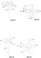
- twisting pin embodiment With reference to Figures 63-66 : twisting pin embodiment.
- a first housing 1801 contains a spiral track 2304 and a plurality of guide grooves 1802 for guiding the movement of each of the tongue features 2004 of the plurality of elongate rigid members 2001.
- a pin 2301 having a shaft 2302 is disposed within the spiral track 2304, wherein the shaft terminates with a tip 2303.
- the tip 2303 may be complimentary to the inner surface portion 2003 of any of the elongate rigid members 2001.
- the tip 2303 and the inner surface portion 2003 may comprise complimentary tapers.
- the pin's tip 2303 sequentially forces the plurality of elongate rigid members 2001 to move away from each other, from an unexpanded passage 1308 and create an expanded passage 1309.
- the pin 2301 may be removed from the spiral track 2304 of the first housing 1801 after the elongate rigid members 2001 are expanded.
- the shaft 2302 of the pin 2301 and the spiral track 2304 comprise a locking mechanism such that the pin 2301 may only move in direction along the spiral track 2304.
- the locking mechanism may comprise complimentary one-way ratchet features on the spiral track 2304 and the shaft 2302.
- the expandable cannula device 100 is comprised from a first housing 2401 with a first throughbore 2404, a hub defining a second throughbore that is continuous with the first throughbore, and comprising at least one rotatable member 2501, a plurality of elongate rigid members 2701 housed and movable within the first housing 2401 and comprising a continuous passage of the expandable cannula device 100, and at least one rigid member 2601 having an outer circumference larger than an inner circumference of a cross-section of the unexpanded passage 1308 defined by the plurality of unexpanded elongate rigid members 2701, wherein the said at least one rigid member 2601 may be housed within the first housing 2401, a coupling mechanism between the at least one rotatable member 2501 and the at least one rigid member 2601 such that the rotation of the at least one rot
- the at least one rigid member 2601 comprises a lumen.
- the lumen comprises a circular cross-section.
- the at least one rotatable member 2501 comprises a rotating component that rotates about a central axis of the first housing 2401, the at least one rigid member 2601 is coupled to the rotating component 2501 by a coupling mechanism that comprises a plurality of wires 2801, which extend from the at least one rigid member 2601 to at one of the plurality of wire threading guide features 2503 which are disposed onto the rotatable member 2501.
- the first housing 2401 comprises a plurality of guide grooves 2402 for allowing the proximal portion of each of the plurality of elongate rigid members 2701 to slide through each of the plurality of guide grooves 2402 when said members move away from the central axis of the first housing 2401.
- the first housing 2401 also comprises a sliding track 2403 onto which the rotatable member 2501 can freely slide/glide when it rotates about the central axis of the first housing 2401.
- the first housing 2401 also comprises a throughbore 2404 that creates a passage that connects to the passage creates by the plurality of elongate rigid members 2701.
- An at least one rigid member 2601 is initially disposed in the throughbore 2404 of the first housing 2401 when the device has an unexpanded passage 1308.
- the at least one rigid member 2601 has a distal edge that is complimentary to the inner tapered surface of the elongate rigid members 2701 (as shown in previous embodiments or examples). The distal edge may be tapered.
- the at least one rigid member 2601 has a plurality of holes 2603 through which the plurality of wires 2801 can be threaded and anchored tightly through these holes 2603.
- the plurality of said wires 2801 extend from the lumen of the expandable cannula device 100 (on the inner surface of the elongate rigid members 2701) towards a distal section of the elongate rigid members 2701 and exit the lumen of the expandable cannula device 100.
- the wires 2801 then are disposed along the outer surface of elongate rigid members 2701 and on the external surface of the first housing 2401 and are then connected and affixed to at least one of the plurality of wire threading guiding features 2503 which are located on the rotatable member 2501.
- the wires may exit the lumen of the expandable cannula device 100 at more proximal section of the elongate rigid members 2701, through holes (not shown).
- the wires may also be housed within a lumen formed along the inner surface of the elongate rigid members 2701, wherein said lumen travels and extends towards the outer surface of the elongate rigid members and may extend to the first housing 2401 as well.
- the rotation of the rotatable member 2501 about the central axis of the first housing 2401 causes the plurality of the wires 2801 to become tensioned and pulled. This in turn causes the at least one rigid member 2601 to advance into a distal position in the expandable cannula device 100, thereby pushing the plurality of elongate rigid members 2701 away from each other towards an expanded state.
- the at least one rigid member 2601 has central througbore that creates a lumen that is continuous with the lumen created by the plurality of the elongate rigid members 2701 and with the lumen of the first housing 2401 that is created by the throughbore 2404.
- the at least one rotatable member 2501 comprises a system of mechanical gears with at least one handle extending outside of the first housing 2401.
- the system of mechanical gears comprises a system of worm-drives, such that the rotation of a first rotatable member 2501, causes the rotation of a first worm wheel 2504 along an axis perpendicular to the axis of the first rotatable member 2501.
- the first worm wheel 2504 further comprises a shaft and threads (worms) that are configured to cause rotation of a second worm wheel 2505 and a third worm wheel 2506 in opposite directions, wherein the axes of the second worm wheel 2505 and third worm wheel 2506 are perpendicular to the axis of the first worm wheel 2504.
- Disposed onto the shaft of the second worm wheel 2505 is a first roller drum 2507, and onto the shaft of the third worm wheel 2506 is a second roller drum 2508, wherein the first roller drum 2507 and second roller drum 2508 rotate in opposite directions to each other when the rotatable member 2501 is rotated.
- a coupling mechanism is disposed between each of the first roller drum 2507, the second roller drum 2508 and the at least one rigid member 2601.
- the coupling mechanism comprises at least one conveyor belt.
- a first conveyor belt 2802 is connected to the first roller drum 2507, and a second conveyor belt 2803 is connected to the second roller drum 2508.
- Each of the first conveyor belt 2802 and second conveyor belt 2803 comprise a loop that extends from the inner surface of the elongate rigid members 2701, and then to the outside surface of the elongate rigid members, and back to the first housing 2401.
- the conveyor belts may exist the elongate rigid members 2701 at a more proximal region through holes in the body of the elongate rigid members 2701 (not shown).
- the first housing 2401 comprises an opening 2405 for introducing the at least one rigid member 2601 into its throughbore 2404.
- the at least one rigid member 2601 may be introduced into the housing via removable cartridge insertion mechanism such that the cartridge can be removed after the at least one rigid member 2601 is introduced into the throughbore 2404 of the first housing 2401.
- the at least one rigid member 2601 becomes sandwiched between the first conveyor belt 2802 and second conveyor belt 2803, wherein a frictional connection is formed between the first conveyer belt 2802 and second conveyor belt 2803 and the at least one rigid member 2601, such that the rotation of the rotatable member 2501 causes the first conveyor belt 2802 and second conveyor belt 2803 to move into a distal direction, and forces the at least one rigid member 2601 to move along with it due to friction.
- Rotation of the rotatable member 2501 in an opposite direction causes the first roller drum 2507 and second roller drum 2508 to rotate in an opposite direction, and thus the first conveyor belt 2802 and second conveyor belt 2803 move from a distal to proximal direction, therefore, bringing the at least one rigid member 2601 towards throughbore of the first housing 2401.
- first conveyor belt 2802 and second conveyor belt 2803 are made from a stretchable elastic material, such that the total length of each belt may be extended.
- first conveyor belt 2802 and second conveyor belt 2803 may comprise a derailleur-like system that maintains a level of tension of each of the belts by adjusting their effective length while the elongate rigid members 2701 are moving away from each other.
- first conveyor belt 2802 and second conveyor belt 2803 may comprise chains.
- at least one rigid member 2601 may comprise an outer surface with gear features that are complimentary with said chains.
- an expandable cannula device 100 comprises a similar mechanism of the one above wherein the first conveyor belt 2802 and second conveyor belt 2803 comprise wires that are attached to the at least one rigid member 2601, wherein said wires extend through the passage defined by the elongate rigid members 2701, and extend towards the external surface of the elongate rigid members and up to the first housing, where they are then are attached to the first roller drum 2507 and second roller drum 2508, such that the rotation of the rotatable member 2501 causes the first roller drums 2507 and second roller drum 2508 to tension the wires and wound them, thereby pulling the at least one rigid member 2601 distally into the unexpanded passage 1308, causing the elongate rigid members 2701 to move away from each other and form an expanded passage 1309.
- the at least one rigid member 2601 may comprise a lumen with a generally circular cross-section.
- the at least one rotatable member 2501 may comprise a locking mechanism for preventing or restricting the at least one rotatable member 2501 from causing the at least one rigid member 2601 from axially moving relative to the first housing 2401.
- the locking mechanism may comprise one-way rotational movement locking mechanisms, such as one-way ratchet gears, or other rotational locking mechanisms known to the those familiar with mechanical arts.
- the at least one rotatable member 2501 may be driven by a motor.
- the motor may be electrically operated, battery operated or pneumatically operated.
- the first housing 3501 comprises a plurality of pin grooves 3502 and a plurality of additional pin grooves.
- a pin 3401 is placed into the pin groove 3502 Such that a portion of it is protruding outside of the pin groove 3502.
- the pin 3401 is removable. The protruding portion of the pin 3401 prevents the stopping face 3602 of the second housing 3601 from moving in an axial direction relative to the central axis of the first housing 3501 and thus controls the level of expansion of the elongated rigid members 3701 away from each other.
- the pin 3401 can be further inserted into the pin groove 3502 or can be removed entirely from the pin groove 3502 such that the second housing 3601 is permitted to move in an axial direction relative to the central axis from the first housing 3501 in order to further expand the expandable cannula device 100 by moving the elongate rigid members 3701 further away from each other.
- a system of pin 3401 and pin groove 3502 and additional pin 3402 and additional pin groove provide a stepwise control for the expansion of the expandable cannula device 100.
- the pin 3401 and pin grooves 3502 comprise a "retractable pen” mechanism such that the pins 3401 can be pushed into the pin grooves 3502 by a pressing action, and then retracted by another pressing action in order for the device to be reused.
- the pins 3401 and pin groove 3502 may be located on the proximal surface of the first housing 1801, in order to control the level of threaded rotation (and thus distal insertion) of the actuating member 1901, and thus the amount of expansion of the expanded passage 1309. In some other embodiments (not shown), the pins 3401 and pin grooves 3502 may be located on the inner surface of the first housing 1801 in order to limit the distal insertion of the actuating member 1901 and thus control the amount of expansion of the expanded passage 1309.
- the expandable cannula device 100 may be configured to be in an initial expanded passage 1309 state, and there is a need to contract it.
- the pins 3401 and pin groove 3502 embodiments described above may be used to provide step-wise contraction control as well.
- the expandable cannula device 100 may be configured to be in an initial expanded passage 1309 state, and there is a need to contract it towards an unexpanded passage 1308, wherein the above mechanism can be used to provide a controlled step-wise contraction.
- the first housing 3801 comprises a pinhole 3802, and the second housing 3901 comprises a pinhole 3902.
- the expandable cannula device 100 has an unexpanded passage 1308 defined by unexpanded elongate rigid members 4101
- the pinhole 3802 of the first housing 3801 and the pinhole 3902 of second housing 3901 have axes that are parallel but are at an offset distance from each other. This forces the pin 4001 which is attached to a compression spring to remain inside the first housing 3801 pinhole 3802 and causes the compression spring to become a compressed compression spring 4002.
- the pins 4001 and the uncompressed compression spring 4003 may be pushed manually towards the first housing 3801 pinhole 3802, where the compression spring becomes a compressed compression spring 4002 again, and motion of the second housing relative to the first housing is permitted.
- a system of a plurality of pins 4001, springs, and pinholes 3802 on the first housing 3801 and pin holes 3902 on the second housing 3901 allows for a step-wise expansion.
- the location of the pins 4001 and the springs can be reversed from the first housing 3801 pinhole 3802 to the second housing 3901 pinholes 3902.
- the compressed compression springs 4002 and pin 4001 may be located on the pinholes 3902 of the second housing 3901.
- the spring becomes an uncompressed compression spring 4003 when the axes of the pinholes 3802 and 3902 are colinear, such that the pin 4001 is advanced from the second housing 3901 pinhole 3902 to the first housing 3801 pinhole 3802, while having a portion of it remaining in the second housing 3901 pinhole 3902 in order to relative prevent axial movement between the first housing 3801 and second housing 3901.
- the expandable cannula device 100 may be configured to be in an initial expanded passage 1309 state, and there is a need to contract it towards an unexpanded passage 1308.
- the spring and pin hole embodiments described above may be used to provide step-wise contraction control as well.
- an expandable cannula device 100 further comprises a biasing mechanism for biasing the plurality of elongate rigid members 4301. This example is not encompassed by the wording of the claims.
- the first housing 4201 (in other examples can be the second housing or both the first and second housing) comprises a biasing mechanism mounting wall 4202 at position in the groove 4203 where elongate rigid members 4301 slide relative to central axis of the expandable cannula device 100. Disposed between the outer surface of the elongate rigid members 4301 and the biasing mechanism mounting wall 4202 is a biasing mechanism.
- the biasing mechanism comprises an uncompressed compression spring 4401, which causes the elongate rigid members 4301 to remain in an unexpanded position and close to each other thus create an unexpanded passage 1308. This prevents accidental sliding of the elongate rigid members 4301 in the grooves of the first housing 4201 and thus accidental expansion of the passage.
- the biasing mechanism may be comprised of a compressible foam material.
- the spring is a tension spring, configured to bias the elongate rigid members 4301 to a position away from central axis of the expandable cannula device 100.
- the expandable cannula device 100 further comprises a guiding mechanism for preventing the elongate rigid members 4601 from moving radially.
- the guiding mechanism comprises complimentary one-way ratchet features, such that the movement of elongate rigid members 4601 is constrained to one radial direction.
- the first housing 4501 (in other examples this may be can be the first and/or the second housing) comprises ratchet features 4502 in the guiding grooves 4503 where the elongate rigid members 4601 can slide to expand the unexpanded passage 1308 of the expandable cannula device 100 and move away from each other and from an expanded passage 1309.
- the elongate rigid members 4601 in this example have complimentary ratchet features 4602, such that once they are expanded from a first position to a second position, the ratchet features 4502 and complimentary ratchet features 4602 prevent the elongate rigid members 4601 from returning to the first position. This example forces a one-way expansion for the expandable cannula device 100.
- the ratchet features 4502 and complimentary ratchet features 4602 are located on the outer surface of the first housing 1101 and the inner surface of the second housing 1201.
- the concentricity features 1205 and complimentary concentricity features 1104 described in previous examples may further comprise ratchet features 4502 and complimentary ratchet features 4602 respectively.
- the ratchet features 4502 and complimentary ratchet features 4602 may be placed on the threaded features 1404 of the first housing 1401 and the threaded features 1503 of the second housing 1501 of an example of the expandable cannula device 100.
- the ratchet features 4502 and complimentary ratchet features 4602 may be placed on the threaded features 1803 of the first housing 1801 and the threaded features 1902 of an actuating member 1901.
- the ratchet features 4502 and complimentary ratchet features 4602 can be reversed in direction, such that an expanded expandable cannula device 100 with an expanded passage 1309 may only be contracted to an unexpanded passage 1308 where the elongate rigid members 4601 come close to each other.
- hinged elongate rigid members there is an example of hinged elongate rigid members. This example is not encompassed by the wording of the claims.
- the expandable cannula device 100 is composed of a first housing 2901 with a central throughbore similar to previous embodiments or examples, a plurality of hinged elongate rigid members 3001 which are connected via hinges 3101 to the first housing 2901 and via another set of hinges 3101 to another set of plurality of hinged elongate rigid members 3001, wherein the plurality of hinged elongate rigid members 3001 cooperatively define a passage that is aligned with the central throughbore of the first housing 2901.
- a compressive sleeve 3201 surrounds outer circumference of the plurality of hinged elongate rigid members 3001 and restricts their radial movement. In some examples, the compressive sleeve 3201 causes the plurality of hinged elongate rigid members 3001 to come in close proximity together and form an unexpanded passage 1308.
- an expansion insert 3301 into the expandable cannula device 100 causes the hinged elongate rigid members 3001 to move away from each other, while the compressive sleeve 3201 prevent them from becoming loose and conforming to shape dictated by the forces of gravity.
- the expansion insert 3301 may comprise a central lumen that has a diameter that is larger than the diameter formed by the unexpanded passage 1308 and permits the passage of instruments and specimen through it.
- the hinges 3101 comprise ratchet features 3102 such that movement of hinged elongate rigid members 3001 is possible in only one direction.
- the ratchet features 3102 may prevent collapse of expanded hinged elongate rigid members 3001 from a larger diameter to a smaller diameter due to the compressive sleeve 3201, especially after the removal of an expansion insert 3301 from the expanded passage 1309 of the expandable cannula device 100.
- the expansion insert 3301 is an insertable member 4901 similar to other insertable members of other embodiments or examples in this disclosure.
- the compressive sleeve 3201 is comprised of an elastic polymer. In some embodiments, the compressive sleeve 3201 is also a fluid leakage prevention seal that prevents any media to be transmitted through the gaps between the expanded hinged elongate rigid members 3001.
- the expandable cannula device 100 further comprises an insertable member 4901 insertable into the central passage by an elongate device.
- the insertable member 4901 comprises a short axial length and a central lumen 4903.
- the elongate device comprises an obturator 5001.
- a distal portion of an obturator 5001 is insertable into the lumen 4903 of said insertable member 4901.
- the outer diameter cross-section of the insertable member 4901 comprises a diameter that is larger than the diameter comprised by the internal diameter cross-section of the unexpanded passage 1308 of an expandable cannula device 100.
- the assembly of obturator 5001 and insertable member 4901 may be advanced into an unexpanded passage 1308 of an expandable cannula device 100.
- the insertion of the insertable member 4901 distally into the expandable cannula device 100 causes the plurality of elongate rigid members 2001 to move away from each other by sliding into the guide grooves 1802 of the first housing 1801 and creating an expanded passage 1309.
- the elongate rigid members 2001 comprise an inner surface portion 2003 and the insertable member 4901 comprises a complimentary external surface 4906 that facilitates its insertion towards a distal portion and facilitates the transmission of forces in order to slide the plurality of elongate rigid members 2001 away from each other.
- the complimentary surfaces comprise complimentary tapers.
- the insertable member 4901 after the insertable member 4901 is delivered towards a distal position of the expandable cannula device 100, it is in contact and is held firmly by the elongate rigid members 2001, especially if the expandable cannula device 100 is expanded inside a subject's tissue, where the tissue may also add a compressive force onto the external surface of the elongate rigid members 2001. Since the insertable member 4901 is held firmly, the obturator 5001 can be removed from the expandable cannula device 100, which leaves the expanded expandable cannula device 100 having a continuous lumen from the first housing 1801 down towards the expanded passage 1309 defined by the plurality of expanded elongate rigid members 2001.
- the short insertable member 4901 and the obturator 5001 may be coupled by threads or by reversable coupling mechanisms that are known to the experienced in the mechanical arts, such as spring-loaded pins.
- the external surface of the short insertable member 4901 may be coupled to the internal surface of the elongate rigid members 2001 by threaded mechanism or by other reversable coupling mechanism that are known to the experienced in the mechanical arts.
- the obturator 5001 comprises a hollow shaft, wherein said shaft is terminated distally by the obturator tip 5004.
- the obturator 5001 is made from optically transparent or translucent material.
- a medical imaging probe such as a laparoscope may be inserted into the said hollow shaft of the obturator but may not protrude past the tip 5004.
- the expandable cannula device 100 further comprises an insertable member 4901 configured to be inserted into the passage of the expandable cannula device 100 that is defined by the plurality of elongate rigid members 2001.
- the insertable member 4901 is inserted into an unexpanded passage 1308 or an expanded passage 1309.
- the insertable member causes expansion and has a lumen.
- the insertion of the insertable member 4901 into the passage of the expandable cannula device 100 causes the plurality of elongate rigid members 2001 to move away from each other if a cross-section of the unexpanded passage 1308 is smaller than a cross-section of the insertable member 4901.
- the insertable member 4901 defines a lumen 4903.
- the lumen is generally cylindrical.
- This embodiment shows an insertable member 4901 comprising at least one valve disposed in its lumen 4903.
- the valve comprises a one-way fluid valve 5501
- the least one one-way fluid valve 5501 is disposed at a proximal region of the insertable member 4901. Said one-way fluid valve 5501 function is to prevent backflow of injected fluids from a proximal region of the insertable member towards the distal region of the insertable member.
- one-way fluid valves 5501 are known to the skilled in the art and can be used here.
- the expandable cannula device 100 may further comprise a first obturator 5001 insertable through the lumen 4903 of the insertable member 4901.
- the first obturator 5001 and the lumen 4903 cooperatively define a threaded fit such that the first obturator 5001 is capable of threaded movement relative to the insertable member 4901.
- the insertable member 4901 comprises a lumen 4903. In some embodiments, there may be internal threaded features 4902 on the internal surface of the insertable member 4901. In some embodiments, an obturator 5001 maybe inserted through the lumen 4903 of the insertable member 4901 and the obturator-insertable member assembly can be inserted into the passage of the expandable cannula device 100
- the obturator 5001 comprises a proximal handle 5002 that can be manipulated by the user.
- the obturator 5001 may comprise threaded features 5003 on the external surface of the obturator that allow the obturator 5001 to become threadedly coupled to the insertable member 4901.
- the obturator 5001 comprises a distal tip 5004.
- the distal tip 5004 may be blunt.
- the obturator may comprise a tapered distal tip 5005.
- the tapered distal tip 5005, may be sharp.
- the insertable member 4901 may be inserted through the expanded passage 1309 of an expandable cannula device 100. In some embodiments, the insertable member 4901 may be inserted through the unexpanded passage 1308 of an expandable cannula device 100. In some embodiments, the lumen 4903 of the insertable member 4901 may comprise a larger cross section than cross section of an unexpanded passage 1308. Thus, by inserting said insertable member 4901 into the unexpanded passage 1308, the elongate rigid members 1301 move away from each other and create an expanded passage 1309 that has a diameter at least equivalent to the outer diameter of the insertable member 4901 that is in contact with the internal surface of the plurality of elongate rigid members 1301. In some embodiments, the size of the expanded passage 1309 can be selected by selecting an insertable member 4901 of a specific outer diameter.
- the obturator 5001 may be coupled to the insertable member 4901, wherein the assembly of both the obturator 5001 and insertable member 4901 are inserted into the passage of the expandable cannula device 100, such that when the insertable member 4901 is in the passage, the obturator 5001 may be removed, such that the lumen 4903 of the insertable member 4901 creates a passage that is concentric with the passage of the expandable cannula device 100.
- This embodiment shows an insertable member 4901 with a plurality of frictional surface reliefs (non-smooth features 5601) disposed onto the exterior surface of the insertable member 4901.
- said non-smooth features 5601 create better retention and stability of expandable cannula device 100 in the tissue and prevent accidental dislodgment of the expandable cannula device 100 outside of the tissue.
- the non-smooth features 5601 comprises ratchet features. In some embodiments (not shown), the non-smooth features 5601 may comprise pattern of pins, threaded features, and ribbed walls.
- the non-smooth features 5601 are housed within the walls of the insertable member 4901 and may be ejected outwards by an actuation mechanism.
- the actuation mechanism may be reversable such that the non-smooth features 5601 are retracted back into the walls of the insertable member 4901.
- said actuation mechanism comprises obturator 5001 insertion distally into the lumen 4903 of the insertable member 4901. In some embodiments (not shown), the actuation mechanism comprises obturator 5001 removal from a distal position within the lumen 4903 of the insertable member 4901 towards a proximal region. In some embodiments (not shown), the actuation mechanism comprises rotation of an obturator 5001 in the lumen 4903 of the insertable member 4901.
- the actuation mechanism comprises rotation the insertable member 4901 about the central axis of the expandable cannula device 100. In some embodiments, the actuation mechanism comprises insertion of an additional insertable member 4901 which does not have non-smooth features 5601 inside the lumen of the first insertable member 4901 that comprises the non-smooth features 5601.
- the movable non-smooth surface features and mechanisms for moving them may be utilized in existing cannulas or trocars (not shown).
- the first obturator 5001 comprises a distal tip 5004 that is not sharp (blunt).
- insertable member is shown as having a circular cross section.
- the insertable member 4901 comprises a generally circular or oval cross-section that transverses a length of the insertable member 4901.
- the insertable member 4901 has at least one handle 4904.
- the handle 4904 may be used to push the insertable member 4901 into a distal part of the expandable cannula device 100.
- the handle 4904 may be used to apply a rotational or pushing motion or a combination of rotation and pushing motions onto the insertable member 4901.
- the insertable member 4901 has an external surface that is complimentary to the internal surface of at least a portion of the first housing.
- the complimentary surfaces comprise complimentary tapers.
- the insertable member 4901 and the first housing cooperatively define a threaded connection such that the insertable member 4901 may threadedly move relative to the first housing when the insertable member 4901 is rotated.
- the insertable member 4901 has an external surface 4906 that is complimentary to the inner surface portion 2003 of some embodiments of the elongate rigid member 2001.
- the complimentary surfaces comprise complimentary tapers.
- the insertable member 4901 may comprise external threaded features 4907 for being threadedly coupled and advanced distally into the first housing of some previous embodiments.
- a first insertable member 4901 comprises an actuating member 1901 with a throughbore 1903; the throughbore 1903 further comprises an internal surface 4905 complimentary to a second insertable member 4901 that is insertable through the throughbore 1903, wherein the second insertable member 4901 comprises a portion with an external shape complimentary to the internal surface 4905 of the actuating member 1901.
- the complimentary surfaces comprise complimentary tapers.
- the actuating member 1901 comprises a first insertable member 4901 with a first lumen 4903.
- the first lumen 4903 comprises an internal surface 4905 complimentary to a second insertable member 4901 (not shown) that is insertable through the first 4903 lumen
- the second insertable member 4901 comprises an external shape complimentary to the internal surface 4905 of the first insertable member 4901.
- the complimentary surfaces comprise complimentary tapers.
- the plurality of elongate rigid members 5101 and the insertable member 4901 cooperatively define a guidance mechanism for limiting an angular position of the insertable member 4901 relative to the plurality of elongate rigid members 5101.
- the guidance mechanism is configured to stop the insertable member 4901 from extending in the passage beyond a predetermined position.
- the guidance mechanism comprises at least one tongues and at least one groove between the insertable member 4901 and the plurality of elongate rigid ember 5101.
- the insertable member 4901 comprises at least one feature 4908 that is complimentary to feature 5102 on the internal surface of the elongate rigid members 5101.
- the feature 4908 comprises a tongue and the feature 5102 comprises complimentary groove.
- the feature 5102 comprise a limited depth 5103 along the length of the elongate rigid member 5101, such that the insertable member 4901 may not be inserted past a more distal region into the expanded passage 1309 of the expandable cannula device 100.
- features 4908 and features 5102 are reversed such that features 4908 comprise grooves and feature 5102 comprise complimentary tongues.
- the expandable cannula further comprises a second biasing mechanism for biasing the insertable member 4901 toward the plurality of elongate rigid members 1301.
- the biasing mechanism causes an increase of an overlap between the insertable member 4901 and the elongate rigid members 1301, such that expansion of the elongate rigid members 1301 is effected.
- the insertion of an insertable member 4901 into the expanded passage 1309 of the expandable cannula device 100 may occur simultaneously while the expandable cannula device 100 is expanded, instead of having to insert said insertable member 4901 after the expandable cannula device 100 is expanded, thus saving time and making the process more streamlined for the user.
- an insertable member 4901 is housed within the throughbore 1103 of the first housing 1101 such that the insertable member 4901 is in a proximal region to the unexpanded passage 1308 that is defined by the plurality of elongate rigid members 1301.
- the first housing 1101 further comprises a member 5201 attachable to the proximal surface region of the first housing 1101.
- the member 5201 further comprises a central lumen.
- the insertable member comprises at least one biasing member connected from insertable member 4901 to the member 5201.
- the biasing member comprises a compression spring.
- the cross-section of the outer diameter of the insertable member 4901 is larger than the cross-section of the inner diameter of unexpanded passage 1308 of the expandable cannula, which prevents the insertable member 4901 from being able to advance into the unexpanded passage 1308 defined by the plurality of elongate rigid members 1301. This causes the at least one spring to become a compressed spring 5202 such that the insertable member remains proximal to the unexpanded passage 1308.
- the insertable member 4901 is inserted into the expanded passage 1309 by the at least one compressed spring 5202 releasing its potential energy and becoming an uncompressed spring 5203.
- the insertable member 4901 further comprises a flexible sealing member, wherein the movement of the insertable member 4901 relative to the first housing causes the flexible sealing member to expand or retract.
- the flexible sealing member with a central lumen is attached to the proximal part of the insertable member 4901, such that when the insertable member 4901 is in the first housing, the flexible sealing member is axially contracted 5401, and when the insertable member 4901 is inserted distally to cause the unexpanded passage 1308 of the expandable cannula device 100 to become an expanded passage 1309, the flexible sealing member becomes an axially expanded member 5402.
- the axially expanded member 5402 creates a sealing mechanism against fluid leakage through expanded passage 1309 of the expandable cannula device 100.
- the flexible sealing member is made from a thin but difficult to stretch polymeric material, such as Polyether block amide (pebax). In some embodiments, it is made from nylon. In some embodiments, the flexible sealing member is made from hard material such as plastic or metals and is comprised from a plurality of hinged disks (not shown).
- the insertion of the insertable member 4901 into the passage of the cannula enhances the stability and load-bearing capacity of the plurality of elongate rigid members 1301 that define said passage by comprising an additional load-bearing member along the inner surface and a portion of the length of the elongate rigid members 1301.
- the additional load-bearing provided by the insertable member 4901 may prevent the elongate rigid members 1301 from bending towards the central axis of the expandable cannula device 100.
- the elongate rigid members 4701 comprise a plurality of frictional surface reliefs (non-smooth features) on its external surface.
- the non-smooth features comprise stability features 4801.
- the stability features 4801 comprise patterns comprising at least one of ratchets, ribbed surfaces, threaded surfaces and pins.
- the stability features 4801 are reversibly movable away from the exterior surface of the at least one of the elongate rigid members 4701 via an actuation mechanism.
- the actuation mechanism comprises the insertion, or removal or rotation of an insertable member 4901 or of an obturator 5001 through the passage defined by the plurality of elongate rigid members 4701.
- the stability features 4801 are retractable. In some embodiments, the retractable features are disposed in a pattern of holes that traverse the cross section of the elongate rigid member 4701:
- the holes for stability features 4801 are situated at an angle relative to the long axis of the elongate rigid member 4701. In some embodiments, there is at least one stability feature 4801 in each hole.
- the stability features 4801 comprise a stopping feature 4802.
- the stopping feature 4802 comprises an enlarged portion that is larger than the diameter of the hole to ensure that the stability feature 4801 does not pass entirely through the hole.
- stopping features 4802 are made from substantially flexible material that may change its original shape when subject to particular mechanical pressure.
- the stopping features 4802 may be comprised of a fluid filled sac.
- all stability features 4801 are configured such that their distal stopping ends are flush with the outer surface of the elongate rigid member 4701.
- the stability features 4801 are configured in an initial retracted position.
- the stability features 4801 are pushed back towards the retracted position by the tissue.
- the stability features 4801 are biased towards the retracted position.
- the biasing mechanism comprises springs.
- the inner ends of the stability features 4801 comprise a circular pattern in the passage defined by the plurality of elongate rigid members 4701.
- the stability features 4801 are ejected in an outwards direction by an actuation mechanism.
- the actuation mechanism comprises an actuation member.
- the actuation member comprises an insertable member 4901. In some embodiments, the actuation member comprises an obturator 5001. In some embodiments, the actuation member is an assembly comprised of both the insertable member 4901 and the obturator 5001.
- the insertion of an actuation member from a proximal point towards a distal point through the unexpanded passage 1308 or expanded passage 1309) defined by the plurality of elongate rigid members 4701, causes the stability features 4801 to be ejected outwards.
- the removal of an actuation member causes the stability features 4801 to become retracted.
- the holes are angled in direction that is defined from inner surface distal point of an elongate rigid member 4701 towards an outer surface proximal point of the same elongate rigid member 4701.
- the movement of an actuation member from distal portion of the expandable cannula device 100 towards a proximal portion of the cannula causes the ejection of the stability features 4801.
- the opposite movement of said actuation member causes the retraction of said stability features 4801.
- the rotation of an actuation member about the central axis of the expandable cannula device 100 in a first direction causes the ejection of the stability features 4801.
- the rotation of said actuation member about central axis of the expandable cannula in an opposite direction of first direction causes the ejected stability features 4801 to become retracted.
- insertable member creates a seal.
- the insertable member 4901 cooperates with, for example, the plurality of elongate rigid members 2001, or 1201, or 4701 to create a seal between each adjacent elongate rigid members 2001, or 1201, or 4701, when the insertable member 4901 is inserted into the expanded passage 1309.
- Insert has complimentary shape to the struts:
- the insertable member 4901 has an external surface 4906 that is complimentary to the inner surface portion 2003 of some embodiments or examples of the elongate rigid member 2001.
- the complimentary surfaces comprise complimentary tapers.
- the external surface 4906 is frustoconical. In some embodiments (not shown), the external surface 4906 is located on a proximal region of the insertable member 4901.
- the elongate rigid members 4701 comprise a plurality of non-smooth features on its external surface.
- the non-smooth features comprise stability features 4801.
- the stability features stability features 4801 comprise patterns comprising at least one of ratchets, ribbed surfaces, threaded surfaces and pins.
- the stability features 4801 are move away from the exterior surface of the at least one of the elongate rigid members 4701 when the plurality of elongate rigid members when the plurality of elongate rigid members 4701 define an expanded passage 1309. In some embodiments, the stability features 4801 retract when the plurality of elongate rigid members define an unexpanded passage 1308.
- At least one inflatable balloon is disposed at an end, away from the housing(s), of at least one of the plurality of elongate rigid members 5101.
- the inflatable balloon is configured to be inflated after the expandable cannula device 100 is inserted into a subject.
- each of the elongate rigid members 5101 comprise an inflatable balloon.
- the inflatable balloon is disposed near the distal end of the elongate rigid members 5101.
- the each of the inflatable balloons are connected in a parallel configuration to an inflation port that is disposed on the proximal part of the expandable cannula device 100.
- the expandable cannula device 100 is inserted into a subject's tissue while the plurality of inflatable balloons are uninflated, and after the distal ends of the elongate rigid members 5101 have penetrated the tissue, the inflatable balloons are inflated by injecting fluid through the inflation ports.
- the inflatable balloons may be inflated when the expandable cannula device 100 is unexpanded. In some embodiments, the inflatable balloons may be inflated after the expandable cannula device 100 is expanded in the tissue.
- the inflated balloons prevent accidental retrieval or dislodgement of the expandable cannula device 100.
- the inflated balloons may be deflated by the user through the inflation port, and the cannula may be removed from the subject's tissue.
- the balloons are made from nylon or pebax.
- the inflation fluid may be gaseous or liquid.
- At least one proximal slider are disposed on the proximal part of the plurality of elongate rigid members 5101, such that the proximal slider is brought distally to sandwich the tissue between the proximal slider and the inflated inflatable balloons.
- each of the elongate rigid members 1301 defines an outer surface taper 1304 extending from the first housing 1101.
- the expandable cannula device 100 may further comprise a second obturator 1001 for penetrating said expandable cannula device 100 into tissue of a subject.
- the obturator 1001 may be inserted into the first housing throughbore 1103, all the way through the unexpanded passage 1308 so that the obturator tip 1003 is exposed prior to inserting the expandable cannula device 100 into tissue.
- the obturator 1001 has an exterior surface 1002 that is complimentary to the interior surface 1307 of the elongate rigid members 1301.
- the exterior surface 1002 of the obturator 1001 and the interior surface 1307 of elongate rigid members 1301 may be tapered. By applying force onto the obturator 1001, the obturator tip 1003 penetrates the tissue.
- the obturator 1001 can be removed such that an unexpanded passage 1308 is created between the external environment and the internal tissue.
- Surgical instruments, specimens, fluids and other material can be passed back and forth from the external environment and into the tissue or vice versa through the passage unexpanded passage 1308, which may be expanded to larger passage, thus comprising an expanded passage 1309 by expansion mechanisms described earlier.
- the obturator 5801 comprises a first insufflation port for injecting gas into a subject tissue cavity after penetrating the tissue.
- the insufflation port is comprised of a stopcock 5802 with a stopcock handle 5803 which controls whether gas insufflation is on or off by being rotated by the user.
- the obturator 5801 comprises a fluid track 5804 that travels from the stopcock 5802 and through the shaft of the obturator towards its distal tip, where the gas would exit.
- This embodiment shows an obturator 5801 with at least one of blade 5805 which is located on the shaft of the obturator 5801.
- the blade 5805 is located at a proximal position relative to the tip of the obturator 5801.
- the blade 5805 is located adjacent to the tip of the obturator 5801.
- the blade 5805 may protrude from the tip 5806 of the obturator 5801.
- the blade 5805 comprises a retractable blade.
- the tip 5806 of the obturator 5801 is a blunt. In some embodiments, the tip 5806 is tapered. In some embodiments, the tapered tip 5806 is sharp.
- an actuation mechanism causes the at least one blade 5805 to become exposed from the shaft of the obturator 5801 when the tip 5806 is under pressure, such as when the obturator 5801 is penetrating a subject tissue, however, as soon as the tip 5806 breaches the tissue layers and pressure is no longer exerted on it, the blade 5805 retracts back into the shaft of the obturator 5801.
- the actuation mechanisms are familiar to the individuals experienced in the art.
- the obturator 5801 comprises tip 5806 that is biased.
- the biased tip 5806 is spring-loaded, such that when the tip 5806 is subjected to pressure, for example when the obturator penetrates a subject tissue, the tip 5806 retracts towards a proximal position, and this retraction of the tip 5806 exposes the at least one blade 5805.
- the obturator 5801 comprises a hollow shaft, wherein said shaft is terminated distally by the obturator tip 5806.
- the obturator 5801 is made from optically transparent or translucent material.
- a medical imaging probe such as a laparoscope may be inserted into the said hollow shaft of the obturator but may not protrude past the tip 5806.
- elongate rigid members 7101 comprise a channel 7102 through which fluid may flow.
- the channel 7102 extends from a location along the elongate rigid member 7101, distally and into the surgical cavity in the subject.
- the channel communicates with a hollow portion 7105 of an obturator 7104 through holes 7108 in the obturator 7104.
- an obturator 7104 from the unexpanded passage 1308 of such a expandable cannula device 100, creates a negative pressure in the penetrated cavity; however, in this embodiment the negative pressure withdraws the fluid in the hollow portion 7105 of the obturator 7104 and causes it to travel through the channels 7102 of each of the elongate rigid members7101 , and finally reach the penetrated cavity, such that that the negative pressure is relieved and an equilibrium of pressure is achieved in the cavity.
- positive pressure in the cavity of patient is generated when an obturator 7104 is inserted through an unexpanded passage 1308 or through an expanded passage 1309 or through the transition between an unexpanded passage to an expanded passage 1309.
- the hollow portion 7105 of the obturator 7104 is open to the external environment, which prevents build up of positive pressure in the cavity of a subject.
- the obturator tip 7106 may contain at least one channel 7107 that is connected to the hollow portion 7105 of the obturator 7104.
- These embodiments may be used as methods of maintaining an equilibrium intracranial pressure during use of a cannula device in minimal invasive brain surgeries.
- each adjacent pair of the plurality of elongate rigid members 1301 comprise a mating mechanism for mating the adjacent pair of the plurality of elongate rigid members 1301.
- the mating mechanism comprises complimentary tongues and grooves.
- the mating mechanism comprises complimentary male and female features.
- the elongate rigid members 1301 comprise a retractable blade. In some embodiments (not shown), the blade is exposed during the expansion of the elongate rigid members 1301 from an unexpanded passage 1308 to an expanded passage 1309.
- moving surfaces may be coated by a lubricant.
- the lubricant may be a polytetrafluoroethylene-based lubricant, a graphite-based lubricant, mineral oil, a silicone-based lubricant, or a poly(p-xylylene) (also known as parylene) based coating.
- ball bearings may also be disposed on said moving surfaces, such as the plurality of first tongue features 1302 and/or the plurality of guide grooves 1102.
- This example shows an expandable cannula device 100 device with at least one one-way fluid valve 5501.
- the one-way fluid valve 5501 is disposed in a proximal region of the first housing 1101.
- the expandable cannula device 100, the at least one one-way fluid valve 5501 comprises an adjustable valve.
- the adjustable valve comprises an inner diameter 6001 and can expand the inner diameter towards a second inner diameter 6009 that is larger than the first inner diameter 6001.
- the adjustable valve is comprised of at least one layer of a plurality of leaflets 6002.
- the plurality of leaflets 6002 comprise an inner diameter 6001, and second inner diameter 6009 of the adjustable valve.
- the inner diameter 6001, and second inner diameter 6009 of the adjustable valve may be adjusted by a driving member 6005.
- the movement of the driving member 6005 is effected by the movement of the elongate rigid members relative to each other.
- the driving member 6005 may comprise a generally circular in shape and defines an axis concentric with the central axis of the expandable cannula device 100.
- the driving member may be an outer ring 6005.
- a first inner diameter 6001 is formed by a plurality of leaflets 6002.
- the leaflets 6002 may be arranged in a generally circular pattern around the central axis of the adjustable valve. In some embodiments, the plurality of leaflets 6002 are arranged in an equidistant pattern.
- each leaflet 6002 may comprise curved edges.
- each leaflet 6002 is pivoted about a pivot pin 6003, wherein the rotation of the pivot pin 6003 about its own axis causes the leaflets to rotate in the same direction about the axis of said pivot pin 6003.
- the pivot pins 6003 are mounted onto a mounting layer 6010 and each pivot pin 6003 is connected to a shaft 6004.
- the shaft 6004 may extend radially outwards, such that the rotation of the shaft 6004 about the central axis of the pivot pin 6003, results in the rotation of the pivot pin 6003 and thus the rotation of the leaflet 6002 about the axis of the pivot pin 6003.
- the degree of rotation of the plurality of leaflets 6002 about the axes of their respective pivot pins 6003 controls the inner diameter 6001, and the second inner diameter 6009 that is comprised by the plurality of leaflets 6002.
- the plurality of shafts 6004 are attached to pin shaft rotators 6012 which are connected to a driving member 6005.
- driving member 6005 comprises a diameter wheel, which comprises a hollow centre 6011.
- the driving member 6005 contains a plurality of pin shaft rotators 6012.
- the pin shaft rotators 6012 are equidistant.
- the number of pin shaft rotators 6012 is equal to the number of pivot pins 6003.
- the pin shaft rotators 6012 comprise rectangular extrusions. In some embodiments, the pin shaft rotators 6012 comprise pivot pins that are connected to the driving member 6005. In some embodiments, the pin shaft rotators 6012 are connected to the driving member 6005 in an equidistant arrangement.
- the driving member 6005 may be rotated with a handle 6006 about the central axis of the adjustable valve, causing the pin shaft rotators 6012 to rotate as well as the plurality shafts 6004 to rotate in the same direction, however about the axes of their respective pivot pins 6003, which in turn causes the leaflets 6002 to rotate about the axes of the pivot pins 6003.
- Rotation of the driving member 6005 about the central axis of the adjustable valve in the first direction causes the leaflets 6002 to rotate towards the central axis of the adjustable valve, and thus decrease the inner diameter.
- Rotation of the driving member 6005 in a second direction that is opposite to the first direction, causes the leaflets 6002 to rotate away from the central axis of the valve, and thus increase the diameter of the valve.
- the driving member 6005 comprises at least one diameter lock pin 6007.
- the diameter lock pin 6007 is disposed into a diameter lock groove 6008. As the driving member 6005 rotates, the diameter lock pin 6007 will contact the edge of the diameter lock groove 6008 to prevent further rotation in a particular direction.
- the elongate rigid member 1301 surfaces that are directly in contact with another surface of a elongate rigid member 1301 has a layer of sealing adhesive such that no fluid leaking gaps are present.
- the sealing adhesive is breakable when the elongate rigid members 1301 are expanded.
- the sealing adhesive is biocompatible.
- the elongate rigid member 6201 surfaces that are directly in contact with another elongate rigid member 6201 surface comprise a gasket 6301.
- the gasket 6301 create a seal between the gaps between each adjacent elongate rigid member 6201 when they are unexpanded.
- each side of gasket 6301 either comprises at least one first gasket feature 6302 and at least one second gasket feature 6303 such that the first gasket features 6302 and second gasket features 6303 are complimentary.
- the complimentary features comprise male and female features.
- the complimentary features comprise tongue and groove.
- the gasket 6301 is comprised from a rubber-based material.
- the expandable cannula device 100 comprises a gasket 6801 that surrounds the plurality of elongate rigid members 1301.
- the gasket 6801 is a telescoping gasket.
- the gasket 6801 is housed within the secondary housing 1201, such that it may be retracted proximally within the secondary housing 1201.
- the gasket handle 6802 When the gasket handle 6802 is pulled in a distal direction towards the plurality of elongate rigid members 1301, the gasket 6801 thus is brought out of the secondary housing 1201 in order to surround the plurality of elongate rigid members 1301 proximal portions that are not penetrated into the tissue.
- the distal most edge of the gasket 6801 makes contact with the top most layer of the subject tissue, such as skin, and therefore creates a closed environment around the expanded passage 1309. This closed environment prevents leakage of fluids, such as insufflated gas, from the lumen of the expandable cannula device 100 to the external environment and vice versa.
- the proximal portion of the gasket is rigid, and the distal part is comprised of gasket material such as rubber.
- the distal most edge of the gasket comprises an adhesive layer.
- the gasket 6801 may be housed within the first or second housings of any of the previously described inventions and embodiments.
- the expandable cannula device 100 comprises an expandable sleeve that surrounds the outer surface of the plurality of the elongate rigid members 6201.
- the sleeve when the elongate rigid members 6201 comprise an unexpanded passage 1308, the sleeve is at a contracted 6401. However, when the elongate rigid members are away from each other and defining an expanded passage 1309 the expandable sleeve becomes expanded 6402 in order to seal the spaces in between the plurality of the elongate rigid members 6201.
- the expandable sleeve is made from a flexible and stretchable material. In some embodiments, the expandable sleeve comprises at least one layer of material. In some embodiment, the expandable sleeve comprises expandable mesh structures. In some embodiments, the expandable sleeve is glued to the outer surface of elongate rigid members 6201. In some embodiments, expandable sleeve is attachably detachable from the expandable cannula device 100.
- the expandable sleeve comprises a central lumen, such that the expandable cannula device 100 is insertably removable from the lumen of expandable sleeve.
- the expandable sleeve is heat-shrinkable.
- This embodiment of an expandable cannula device 100 shows a coiled sheet member 5701 being disposed in the unexpanded passage 1308 of the expandable cannula device 100, wherein the coiled sheet member 5701 further comprises a central passage.
- the coiled sheet member 5701 is comprised of a resilient material.
- the resilient material is metallic or comprised of a metallic composite.
- the coiled sheet member 5701 is made from plastic material.
- the plurality of unexpanded elongate rigid members 1301 keep the coiled sheet member 5701 in its coiled state by applying pressure and constricting the available diameter for the coiled sheet member 5701.
- the coiled sheet member 5701 becomes an uncoiled sheet member 5702 such that a seal is formed along the internal circumference of the expanded passage 1309.
- the coiled sheet member 5701 comprises outer surface features, that are compatible with inner surface features of the elongate rigid members 1301. In some embodiments, the outer surface features can slide in the inner surface features when the coiled sheet member 5701 uncoils to become an uncoiled sheet member 5702.
- the outer surface features may comprise tongues and the inner surface features comprise complimentary grooves, or vice versa.
- the uncoiled sheet member 5702 creates a sealing mechanism against fluid leakage through the instrument.
- the expandable cannula device 100 comprises a contracted sleeve 6501 attached to the sides of each adjacent pair of the plurality of elongate rigid members 6201.
- the contracted sleeve 6501 is configured to be in an accordioned state.
- the contracted sleeve 6501 becomes expanded 6502 in order to seal the spaces in between the plurality of the elongate rigid members 6201.
- the contracted sleeve 6501 may be folded in other shapes or configurations. In some embodiments, the folded portions of the contracted sleeve 6501 are outside the unexpanded passage 1308. In some embodiments, the folded portion of the contracted sleeve 6501 are inside the unexpanded passage 1308.
- a sealing sleeve comprises a magnetic sleeve 6601 and the elongate rigid members 6201 are made from a magnetic material.
- the magnetic sleeve 6601 is disposed onto the external surface of each pair of the plurality of adjacent elongate rigid members 6201.
- the magnetic sleeve 6601 comprises a flexible portion 6602 that conforms to the external shape of the elongate rigid members 6201.
- the magnetic sleeve will seal the gap 6603 between the expanded adjacent elongate rigid members 6201, which is adjacent and may be in direct contact with a second elongate rigid member 6201 when the expandable cannula device 100 comprises an unexpanded passage 1308.
- the expansion of the elongate rigid members 6201 of the expandable cannula device 100 causes the magnetic sleeve 6601 to slide on the external surfaces of the first and second elongate rigid members 6201 and seal the gap 6603.
- a portion of the magnetic sleeve 6601 is permanently fixed to the external surface of a first elongate rigid member 6201, which is adjacent and may be in direct contact with a second elongate rigid member 6201 when the expandable cannula device 100 comprises an unexpanded passage 1308.
- the remaining portion of the magnetic sleeve 6601 is magnetically attached to the external surface of the second elongate rigid member 6201.
- the expansion of the elongate rigid members 6201 of the expandable cannula device 100 causes the magnetically attached portion of the sleeve to slide onto the external surface of the second elongate rigid member 6201 and cover the gap 6603 in between the expanded passage 1309.
- a sliding sleeve 6701 is provided that is mechanically connected to at least one of the pair of elongate rigid members 6201.
- the sliding sleeve 6701 comprises a flexible centre piece 6705, is mechanically connected by movable connection features 6702 to each of two adjacent elongate rigid members 6201, which contain tracks 6703 that guide the movements of the movable connection features 6702.
- the movable connection features 6702 are slideable.
- the movable connection features 6702 comprise at least one wheel that connects to the track 6703 on each of the two adjacent elongate rigid members 6201.
- Each elongate rigid member 6201 comprises a track 6703 in which the movable connection features 6702 slide.
- the track 6703 comprises a groove.
- the track 6703 comprises a wheel rail.
- the at least one movable connection features 6702 are complimentary to the track 6703. In some embodiments, the movable connection feature 6702 comprises a tongue.
- the flexible centre piece 6705 will seal the gap between adjacent unexpanded elongate rigid members 6201.
- the flexible centre piece 6705 changes its conformation to seal the gap between adjacent expanded elongate rigid members 6201 to prevent gas leakage.
- the sliding sleeve 6701 comprises a side sealant 6704 that seals the gap between the sliding sleeve 6701 and the elongate rigid member 6201 in order to prevent fluid leakage.
- a sliding sleeve 6701 is composed entirely of a flexible material.
- the mechanical sliding seal is mechanically connected to two adjacent elongate rigid members 6201 via tongue features that are guided in the tracks 6703 of the elongate rigid members 6201.
- the tracks 6703 are horizontal. This enables the sliding sleeve 6701 to slide horizontally towards the gap between adjacent elongate rigid members 6201 as the elongate rigid members 6201 transition from the contracted to the expanded state.
- the sliding sleeve 6701 will seal the gap between adjacent contracted elongate rigid members 6201 and will change its conformation to seal the gap between adjacent expanded elongate rigid members 6201 to prevent gas leakage.
- the side sealant 6704 is configured to seal the gap between the sliding sleeve 6701 and the elongate rigid member 6201 to prevent gas leakage.
- the external surface of at least one of the plurality of elongate rigid members 6201 comprises graduated markers 6901 for indicating depth of insertion into tissue of a subject.
- the graduated markers 6901 are printed onto the outer surface of said elongate rigid members 6201. In some embodiments, the graduated markers 6901 are engraved on the outer surface of the elongate rigid members 6201. In some embodiments, the depth of insertion of the distal tip of the elongate rigid member 6201 inside the tissue is shown via the graduated markers 6901. In other embodiments, the graduated markers 6901 may reflect the amount of the proximal part of the elongate rigid members 6201 that has not penetrated the tissue.
- the expandable cannula device 100 further comprises a second insufflation port.
- a stopcock 5802 is connected to the first housing 1101 of the expandable cannula device 100, such that a fluid track is created from stopcock 5802 to the central passage of the expandable cannula device 100.
- the expandable cannula device 100 comprises a guide for guiding a blade or an energy cutting device to create an incision of a predetermined dimension and shape.
- the incision making guide 7001 may be part of the first housing 1101 or second housings 1201 of the expandable cannula device 100.
- the incision making guide 7001 has telescoping or retractable mechanism to facilitate moving it from a proximal position to a distal position of the cannula.
- the expandable cannula device 100 is inserted in the tissue at the unexpanded state, the incision making guide 7001 is brought distally, or is expanded, in order to interface the top most layer of the tissue, such as skin.
- unexpanded incision making guide 7001 may be brought down to skin level via a telescoping mechanism 7003, thus becoming an expanded incision making guide 7002.
- the incision making guide 7001 comprises demarcations to help the user in creating an appropriate skin level incision prior to expanding the expandable cannula device 100.
- the incision making guide 7001 can be retracted and returned to its unexpanded position after an incision is made.
- the expandable cannula device 100 may comprise at least one live position tracking feature 7201.
- the live position tracking feature 7201 comprises a plurality of objects that are reflective to electromagnetic energy or are emitters of electromagnetic energy wherein said emitted or reflected energy is detectable by an external position tracking system.
- the live position tracking feature 7201 may be used by an external navigation system to track the position of the expandable cannula device 100 during use.
- live position tracking feature 7201and external navigation systems may track the level of cannula expansion.
- live position tracking feature 7201 may be placed on other members that are inserted or used with the expandable cannula device 100, such as an actuation member, or insertable member, or obturator.
- the live position tracking feature 7201 comprise electromagnetic wave emitting markers. In some embodiments, the live position tracking feature 72011 comprise electromagnetic wave reflective markers. In some embodiments, the live position tracking feature 7201 comprise infrared reflective or emitting markers.
- the live position tracking feature 7201 may comprise x-ray opaque dye, coating or material.
- the live position tracking feature 7201 may be attached to the expandable cannula device 100, at a distance away from it, via an extension arm.
- the expandable cannula device 100 may be held by an external mechanical member.
- the mechanical member may be a pneumatic or hydraulic or robotic arm.
- the expandable cannula device 100 may further comprise a fluid-filled chamber configured to transfer the fluid into an inflatable sac connected to the elongate rigid members.
- the fluid filled chamber may be housed inside the first housing, or second housing, where it would comprise a central lumen.
- chamber may comprise a piston that is connected to the first housing, or second housing, or at least one of the elongate rigid members, such that the expansion of the expandable cannula device 100 causes the piston to become pressed and thus transfer the fluid into the inflatable sacs.
- the contraction of the expanded cannula device 100 reverses the action of the piston, and causes the fluid to be transferred back into the chamber.
- At least one inflatable sac is disposed between two adjacent elongate rigid members.
- the inflatable sac traverses the length of the elongate rigid member, such that when the expandable cannula device 100 is expanded and an expanded passage 1309 is created by the plurality of elongate rigid members, the inflatable sacs become inflated and seal the gaps in between the elongate rigid members.
- FIG. 209-217 there is shown an exemplary expandable cannula device with blades in the elongate rigid members.
- the expandable cannula device 100 may be comprising one uniform passage.
- at least one blade 5905 is disposed in an exterior wall of each of the plurality of elongate rigid members 2001. Wherein the blade 5905 comprises a sharp edge facing an exterior surface of the elongate rigid member 2001 and a spine 5907 facing an interior surface of the elongate rigid members 2001.
- At least one biasing member 5906 disposed in a portion of the wall of the elongate rigid member 2001, the biasing member 5906 biases the at least one blade 5905 away from the exterior surface of the elongate rigid member 2001.
- the biasing member 5906 comprises a compression spring.
- the blade 5905 is movable such that: the sharp edge is embedded in the exterior wall and the spine 5907 is exposed from the interior surface when no force toward the exterior surface is applied on the spine 5907; and the sharp edge is exposed from the exterior surface when a force toward the exterior surface is applied on the spine 5907.
- the force can be exerted on the spine 5907 via an insertable member 5901, such that the insertion of the insertable member 5901 applies a force toward the exterior surface on the spine.
- the insertable member 5901 comprises a first circumference 5902, and a portion of the insertable member 5901 comprising a second circumference 5903 that is larger than the first circumference 5902, such that a force toward the exterior surface on the spine 5907 is applied by the insertable member 5901 when a portion of the insertable member 5901 of the second circumference 5903 is aligned with the spine 5907.
- the biasing member 5906 such as the spring, becomes compressed thus allowing the blade 5905 to move out of the walls of elongate rigid member 2001; and a force toward the exterior surface on the spine 5907 is not applied by the insertable member 5901 when a portion of the insertable member 5901 of the first circumference 5902 is aligned with the spine.
- the insertable member 5901 comprises an obturator.
- the biasing member 5906 such as the spring returns to its uncompressed state, thus biasing the blade 5905 to a position within the walls of the elongate rigid member 2001.
- the second circumference 5903 comprises a surface 5904 that is complimentary to a spine surface 5908 to reduce contact friction.
- the surface 5904 and spine surface 5908 comprise complimentary tapers.
- the blade 5905 after causing the blade 5905 to be exposed during insertion of an insertable member 5901, it may then be removed from the passage of the expandable cannula device 100 without causing a second exposure of the blade 5905 during pullback; this can be accomplished by rotating the obturator such that the spine 5907 is aligned with a portion of the obturator comprising a first circumference 5902. Once the alignment is achieved, the obturator can then be pulled out of the cannula without causing a secondary bladed exposure.
- the expandable cannula device 100 may be used for creating a passage into a subject, said method comprising inserting the expandable cannula device 100 through a tissue the subject and then expand the expandable cannula device 100 by moving the elongate rigid members away from each other.
- the expandable cannula device 100 may start at a passage with 3mm inner diameter, and then be expanded to passage with 12mm diameter or any diameter in between 3mm and 12mm.
- the expandable cannula device 100 may be used for making an entry hole, thereby creating an orifice into a mammalian subject.
- the expandable cannula device 100 may be used for enlarging an orifice by moving the plurality of elongate rigid members away from each other.
- the expandable cannula device 100 may start at a passage with 3mm inner diameter, and then be expanded to passage with 12mm diameter or any diameter in between 3mm and 12mm.
- the expandable cannula device 100 may be used for allowing movements of instruments within and through the expandable cannula device 100.
- minimal invasive tissue visualization and surgical instruments may be used.
- laparoscopic visualization and surgical instruments may be used, and in some examples, minimal invasive brain visualization and surgical instruments may be used.
- the expandable cannula device 100 and any of its components, add-ins and attachments may be fabricated from optically transparent or translucent material.
Landscapes
- Health & Medical Sciences (AREA)
- Life Sciences & Earth Sciences (AREA)
- Surgery (AREA)
- Heart & Thoracic Surgery (AREA)
- Public Health (AREA)
- Animal Behavior & Ethology (AREA)
- Biomedical Technology (AREA)
- Veterinary Medicine (AREA)
- Engineering & Computer Science (AREA)
- General Health & Medical Sciences (AREA)
- Medical Informatics (AREA)
- Molecular Biology (AREA)
- Pathology (AREA)
- Nuclear Medicine, Radiotherapy & Molecular Imaging (AREA)
- Pulmonology (AREA)
- Anesthesiology (AREA)
- Hematology (AREA)
- Surgical Instruments (AREA)
Description
- The technical field relates generally to devices used in minimally invasive surgeries or key-hole surgeries. For example, the technical field relates to cannula devices and trocar devices for insertion in an incision.
- In minimally invasive surgeries, a small incision is made. Then a cannula or a port device (known as trocar) is inserted through the incision to create a tunnel through which surgical devices can be passed through to perform the minimally invasive procedure. The surgeons aim to minimize the size of the tools they use and hence minimize the diameter of the trocars they use in order to minimize scarring, post-operative pain, risk of infection and overall injury. Therefore, the surgeon typically begins the procedure by using a small trocar device. In laparoscopic procedures the small trocars are typically rated at having a cannula with an internal diameter of 5mm, for example. Some instruments however have larger diameter, and therefore require the use of larger diameter trocars such as 10mm or 12mm trocars.
- In the cases where a large trocar (such as 10mm or 12mm trocars) must be utilized, there is a need to reduce the incision size, and the defect size in the patient's anatomy that is caused by insertion of these large trocars. Some large trocars are inserted into tissue with blunt-tip obturators or have obturators with dilating tips obturator in order to reduce injury. However, there are no known trocars with dilating cannula being used in the field.
- In certain situations, a need may arise to enlarge the diameter of a small port in order to use a larger instrument. These situations may be pre-planned or may be due to emergency situations such as a sudden bleeding or may be due to un-anticipated difficult anatomy. Such reasons (and more) would drive the need to upsize the trocar device; to replace small diameter trocar with a larger diameter one instead.
- In laparoscopic surgeries, this upsizing can cause loss of the abdominal pneumoperitoneum, which needs to be re-stablished after the upsizing. It also presents a risk of injury to patient as the secondary trocar insertion may go through a different path through the abdominal wall, presenting an opportunity to injure an internal organ or cause bleeding. Furthermore, conventional upsizing requires that the small incision is increased prior to inserting the larger trocar, and upon the completion of surgery that the fascia and skin are stitched to decrease risk of herniation.
- One popular method of trocar upsizing is to first insert a sleeve device (with mesh and polymer coating) through the abdominal wall, through which, a small trocar is inserted, then upon need of upsizing, a bigger trocar is inserted through the sleeve after the small one has been removed. Although this system prevents need to stitch fascia and abdominal wall after upsizing and prevents the risk of going through a different pathway, it presents few problems. It still allows leakage of gas during upsizing, and the insertion of a larger trocar through the sleeve still requires significant insertion force that present a risk of injury to patient. Furthermore, this method still requires use of 2 trocar devices in addition to the sleeve.
- In some scenarios the trocars used during surgery become dislodged during use, and may sometime be accidentally removed from the tissue, presenting an injury risk upon re-entry, causing inefficiency and pneumoperitoneum loss. Therefore, there is a need of trocars providing better stability and retention in the tissue of the patient.
- In minimal invasive neurosurgeries such as tumor resections, and hematoma evacuations, a cannulation device or a port of a small diameter is often inserted through the brain tissue towards the target site. However, in cases where larger access is needed, the diameter of the cannula may then gradually increased by successive insertion of larger cannulas over the smaller ones. This is a time-consuming process and induces higher stress and risk of damage to the tissue proximal to the skull as the larger cannulas are inserted and an uneven distribution of force is created with a gradient towards the upper portion of the brain tissue. In other techniques when larger access is needed, the insertion of a large diameter port with image guidance technologies may be used. However, insertion of a large diameter port into delicate brain tissue may cause critical tissue and nerve injury. Thus, a more minimally invasive method to create larger access in brain tissue is also needed.
-
US2013/103048 discloses a guide tube used for guiding an instrument through a hole within tissue of a patient. The guide tube includes a cannula member defining a passage extending therethrough along an axis. The passage is operable to receive the instrument and guide the instrument through the hole within the tissue of the patient. The guide tube also includes an expansion member that is moveably coupled to the cannula member to selectively move radially between a retracted position and an expanded position relative to the axis of the cannula member. The expansion member is at least partially insertable into the hole when the expansion member is in the retracted position. The expansion member is operable to engage with a surface of the hole when the expansion member is in the expanded position. - Additional difficulties with existing devices may be appreciated in view of the Detailed Description of Example Embodiments, herein below.
- According to the present invention there is described a cannula device according to the appended claims.
- The cannula device comprises a first housing, a plurality of elongate rigid members, and a second housing. The first housing defines a throughbore. The plurality of elongate rigid members cooperatively defines a passage, which is axially aligned with the first throughbore. The plurality of elongate rigid members is connected to the first housing. The second housing also defines a throughbore. The second housing is connected to the plurality of elongate rigid members and the movement of the second housing with respect to the first housing causes the elongate rigid members to move away from each other and increase the size of the passage.
- The cannula device may further comprise an actuating member. The actuating member also defines a throughbore. When assembled, the throughbore of the actuating member is axially aligned with the passage. The axial movement of the actuating member with respect to the housing causes the plurality of elongate rigid members to radially move relative to each other.
- In an example not encompassed by the wording of the claims, there is described a cannula device that comprises a housing, a plurality of elongate rigid members and an actuating pin. The housing defines a throughbore. The plurality of elongate rigid members is connected to the housing, and the plurality of elongate rigid members cooperatively defines a passage, which is axially aligned with the throughbore. The actuating pin extends through the housing and is in contact with the plurality of elongate rigid members. The actuating pin moves spirally relative to the axis of the throughbore and causes the plurality of elongate rigid members to move radially.
- In an example not encompassed by the wording of the claims, there is described a cannula device that comprises a housing, a plurality of elongate rigid members, a hub, and at least one rigid member. The housing defines a throughbore. The plurality of elongate rigid members is connected to the housing and cooperatively defines a passage that is axially aligned with the throughbore. The hub is connected to the housing and comprises at least one rotatable feature that is coupled to the at least one rigid member so that the rotation of the at least one rotatable feature causes the at least one rigid member to move into and along the passage. The at least one rigid member has a circumference that is larger than an inner circumference of the passage so that the movement of the at least one rigid member causes the plurality of elongate rigid members to move radially away from each other to enlarge the passage.
- In an example not encompassed by the wording of the claims, there is described a cannula device that comprises a housing, a plurality of elongate rigid members, and a compressible member. The housing defines a throughbore. The plurality of elongate rigid members is connected to the housing and cooperatively defines a passage. Each elongate rigid member is hingedly connected to another elongate rigid member. The compressible member is placed around the plurality of elongate rigid members to restrict movement of the elongate rigid members.
- In an example, there is described a cannula device that comprises a cannula with at least one blade, which comprises a sharp edge and a spine, disposed in the exterior wall of the cannula. The blade is biased toward the inside of the cannula, and the sharp edge of the blade is normally embedded within the exterior wall of the cannula, while the spine is exposed from the inside of the cannula. When an outward force is applied to the spine, the sharp edge is exposed from the exterior surface of the cannula.
- In an example not encompassed by the wording of the claims, there is described a method for creating a passage into a subject. The expandable cannula device can be inserted into a subject and then the elongate rigid members are moved away from each other to enlarge the passage. Use of the cannula device is also provided.
- In some embodiments, moveable frictional surface features are provided in the walls of a cannula device defining a passage.
-
-
Figure 1 is an isomeric view of an example expandable cannula device in an unexpanded state, having a push to expand capability. This example is not encompassed by the wording of the claims; -
Figure 2 is a side view of the example expandable cannula device shown inFigure 1 ; -
Figure 3 is a bottom view of the example expandable cannula device ofFigures 1-2 ; -
Figure 4 is an isomeric view of the example expandable cannula device ofFigures 1-3 in an expandable state; -
Figure 5 is a side view of the example expandable cannula device ofFigures 1-4 in the expandable state; -
Figure 6 is a bottom view of the example expandable cannula device ofFigures 1-5 in the expandable state; -
Figure 7 is an isomeric view of an alternative example of an expandable cannula device with guiding members having a larger end. This example is not encompassed by the wording of the claims; -
Figure 8 is a side view of the example expandable cannula device ofFigure 7 ; -
Figure 9 is a portion of rigid members in the cannula ofFigures 1-8 showing a portion containing hidden blades exposed when the rigid members expand. This example is not encompassed by the wording of the claims; -
Figure 10 is a cross-sectional view of the portion containing the blade in the rigid member shown inFigure 9 ; -
Figure 11 is a bottom view of the example ofFigures 9-10 ; -
Figure 12 is an isometric view of a rigid member containing a peg for insertion into an adjacent rigid member at the unexpanded state, and containing a cavity for another peg to be inserted through it from an adjacent rigid member; -
Figure 13 is a bottom view ofFigure 12 ; -
Figure 14 is side view of an example of the cannula device ofFigure 1 with a set screw mechanism for preventing elongate rigid members from moving any further by either forming a physical barrier of moving any further out or by applying downwards pressure on them to prevent motion. This example is not encompassed by the wording of the claims; -
Figure 15 is a close-up view of the set screw feature shown inFigure 14 ; -
Figure 16 is an isometric view of an alternative example of the cannula device ofFigure 1 with a tube with a gasket at the distal end of the tube. The second ring, elongate rigid members forming a cannula are shown at the unexpanded state. This example is not encompassed by the wording of the claims; -
Figure 17 is a cross-sectional side view of the cannula device ofFigure 16 ; -
Figure 18 is an isometric view of the example ofFigures 16-17 , but shown with the rigid members at an expanded state; -
Figure 19 is a cross-sectional side view of the example ofFigure 18 ; -
Figure 20 is an isomeric view of an exemplary expandable cannula device in an unexpanded state, having a pull to expand capability. This example is not encompassed by the wording of the claims; -
Figure 21 is a side view of the exemplary expandable cannula device shown inFigure 20 ; -
Figure 22 is a bottom view of the exemplary expandable cannula device ofFigures 20-21 ; -
Figure 23 is an isomeric view of the exemplary expandable cannula device ofFigures 20-22 in an expandable state; -
Figure 24 is side view of the exemplary expandable cannula device ofFigures 20-23 in the expandable state; -
Figure 25 is bottom view of the exemplary expandable cannula device ofFigures 20-24 in the expandable state; -
Figure 26 is an isometric view of an expandable cannula device with an obturator inserted through said device's passage; -
Figure 27 is a cross sectional view of the exemplary embodiment ofFigure 26 , showing internal mechanism of the expandable cannula; -
Figure 28 is side view of the obturator depicted in the example embodiment shown inFigures 26-27 ; -
Figure 29 is an isometric view of an expandable cannula device embodiment comprising two housings and elongate rigid members, at an unexpanded state, wherein the second housing is farther away from the first housing and the elongate rigid members comprise an unexpanded passage of the cannula; -
Figure 30 is a side view of the exemplary embodiment shown inFigure 29 ; -
Figure 31 is a cross-sectional view of the exemplary embodiment shown inFigure 30 ; -
Figure 32 is an isometric view of an expandable cannula device embodiment shown inFigures 29-31 , at an expanded state, wherein the second housing is moved proximally closer towards the first housing causing the elongate rigid members to move away from each and comprise an expanded passage of the cannula; -
Figure 33 is a side view of the exemplary embodiment shown inFigure 32 ; -
Figure 34 is a cross-sectional view of the exemplary embodiment shown inFigure 33 ; -
Figure 35 is an isometric view of the first housing embodiment shown inFigures 26-34 ; -
Figure 36 is a side view of the exemplary embodiment shown inFigure 35 ; -
Figure 37 is a cross-sectional view of the exemplary embodiment shown inFigure 36 ; -
Figure 38 is an isometric view of the second housing embodiment shown inFigures 26-34 ; -
Figure 39 is a side view of the exemplary embodiment shown inFigure 38 ; -
Figure 40 is a cross-sectional view of the exemplary embodiment shown inFigure 39 ; -
Figure 41 is an isometric view of an example embodiment of one of the plurality of elongate rigid members inFigures 26-34 ; -
Figure 42 is a side view of the exemplary embodiment shown inFigure 41 ; -
Figure 43 is an isometric view of an expandable cannula device embodiment, at an unexpanded state, wherein the second housing is away from the first housing, and rotation of the second housing about the central axis of the device causes movement of the second housing relative to the first housing; -
Figure 44 is a side view of the exemplary embodiment shown inFigure 43 ; -
Figure 45 is a cross-sectional view of the exemplary embodiment shown inFigure 44 -
Figure 46 is an isometric view of the expandable cannula device embodiment shown inFigures 43-45 , at an expanded state, wherein the second housing is moved proximally closer to the first housing, causing the elongate rigid members to move away from each other and comprise an expanded passage; -
Figure 47 is a side view of the exemplary embodiment shown inFigure 46 ; -
Figure 48 is a cross-sectional view of the exemplary embodiment shown inFigure 47 ; -
Figure 49 is a cross-sectional close-up view of the first and second housings of expandable cannula device embodiments ofFigures 43-48 , at an expanded state where the second housing is close to the first housing; -
Figure 50 is an isometric cross-sectional view of an example of an expandable cannula device comprising an insertable member with a telescoping actuation mechanism attached to the second housing, such that movement of the second housing proximally closer to the first housing causes the insertable member to move distally along the central axis of the device. This example is not encompassed by the wording of the claims; -
Figure 51 is a cross sectional close-up view ofFigure 50 , wherein the second housing is away from the first housing, such that the telescoping actuation mechanism is unexpanded and configures the insertable member to be in a proximal region to the plurality of the unexpanded elongate rigid members; -
Figure 52 is a cross sectional close-up view of the same example ofFigures 50-51 , wherein the second housing is moved closer to the first housing, configuring the device to become expanded and causing telescoping actuation mechanism to become expanded and thus move the insertable member distally into the expanded passage comprised by the plurality of elongate rigid members. -
Figure 53 is an isometric view of an example of an expandable cannula device, comprising an actuation member shown in a position proximal to the first housing of an unexpanded configuration of the expandable cannula device embodiment. This example is not encompassed by the wording of the claims; -
Figure 54 is a side view of the example shown inFigure 53 ; -
Figure 55 is a cross sectional view of the example shown inFigure 54 ; -
Figure 56 is an isometric view of the same example ofFigure 53-55 , wherein the actuation member is inserted distally into the first housing, causing the expandable cannula device to become expanded; -
Figure 57 is a side view of the example shown inFigure 56 ; -
Figure 58 is a cross-sectional view of the example shown inFigure 57 ; -
Figure 59 is an isometric view of the expanded configuration of the device ofFigures 56-58 further comprising an insertable member inserted into the expanded passage of the cannula, and an obturator inserted into the lumen of the insertable member. The example in this figure is not encompassed by the wording of the claims; -
Figure 60 is a cross-sectional side view of the example shown inFigure 59 ; -
Figure 61 is an isometric view of the device ofFigures 59-60 , wherein the obturator is removed from the lumen of the insertable member. The example in this figure is not encompassed by the wording of the claims; -
Figure 62 is a cross-sectional side view of the example shown inFigure 61 ; -
Figure 63 is an isometric view of an exemplary expandable cannula device, at an unexpanded state, where a pin is located at a radially close position to the central axis of the device, where expansion of the elongate rigid members is effected by movement of the pin along a spiral track in the first housing. This example is not encompassed by the wording of the claims; -
Figure 64 is a cross-sectional side of view of the example shown inFigure 63 ; -
Figure 65 is an isometric view of the example ofFigures 63-64 , at an expanded state, where the pin is moved to a radially further away point along the spiral track of the first housing. This example is not encompassed by the wording of the claims; -
Figure 66 is a cross-sectional side view of the example shown inFigure 65 ; -
Figure 67 is an isometric view of an example of an expandable cannula device, at an unexpanded state, where expansion of the elongate rigid members is effected by rotating a rotatable member located on the first housing and is connected by wires to a rigid member. This example is not encompassed by the wording of the claims; -
Figure 68 is a cross-sectional side view of the example shown inFigure 67 ; -
Figure 69 is an isometric view of the example ofFigures 67-68 , where the rotatable member is rotated and the cannula is expanded by advancement of a rigid member distally into the passage of the cannula by wires; -
Figure 70 is a cross-sectional side view of the example shown inFigure 69 ; -
Figure 71 is an isometric view of an example of an expandable cannula device, where expansion of the elongate rigid members is effected by rotating a rotatable member located on the first housing and is connected by a mechanical system to conveyor belts which interact with a rigid member to effect expansion of the cannula. This example is not encompassed by the wording of the claims; -
Figure 72 is a cross-sectional side view of the example ofFigure 71 ; -
Figure 73 is an isometric view of the example shown inFigures 71-72 , at an expanded state; -
Figure 74 is a cross-sectional side of view of the example shown inFigure 73 ; -
Figure 75 is a side-view of an example embodiment of an expandable canula device with a plurality of movable pins in the first housing configured to limit the amount of movement of the second housing relative to the first in order to limit the amount of expansion of the cannula; -
Figure 76 is a cross-section of the exemplary embodiment shown inFigure 75 ; -
Figure 77 is a side view of an example of the embodiments shown inFigures 75-76 , where the second housing is constricted by a first pin to move up to a first position; -
Figure 78 is a cross-sectional view of the exemplary embodiment shown inFigure 77 ; -
Figure 79 is a cross-sectional side view of an example of the embodiments shown inFigures 77-78 , wherein the first pin is either inserted into a groove or removed, such that the second housing is movable to a second position where its motion is constricted by a second pin; -
Figure 80 is a side-view of the exemplary embodiment shown inFigure 79 ; -
Figure 81 is a close-up isometric view of the expansion control mechanism shown inFigures 75-80 ; -
Figure 82 is an isometric view of an example embodiment of an unexpanded expandable cannula device with a spring-loaded pin method to lock movement of second housing relative to first housing at a specific position; -
Figure 83 is a cross-sectional side view of the exemplary embodiment of the device shown isFigure 82 -
Figure 84 is an isometric view of the exemplary embodiment of an expanded version of the expandable cannula device inFigures 82-83 , with the second housing movement being locked at a position that prevents the cannula from being further expanded or contracted; -
Figure 85 is a cross-sectional side view of the exemplary embodiment shown inFigure 84 , further illustrating the mechanism; -
Figure 86 is a cross-sectional isometric view of an example of an expandable cannula device with a biasing mechanism, comprising springs, to bias the elongate rigid members towards an unexpanded configuration. This example is not encompassed by the wording of the claims; -
Figure 87 is a cross-sectional side view of the example of the device shown inFigure 86 ; -
Figure 88 is a cross-sectional top view of the example of the device shown inFigures 86-87 ; -
Figure 89 is a cross-sectional isometric view of the example ofFigures 86-88 , with the biasing spring being compressed and the elongate rigid members configured in an expanded position; -
Figure 90 is a cross-sectional side view of the example shown inFigure 89 ; -
Figure 91 is a cross-sectional top view of the example shown inFigures 89-90 ; -
Figure 92 is an isometric top cross-sectional view of an example of an expandable cannula device where the plurality of elongate rigid members and the grooves of the housing in which they slide to expand comprise one-way ratchet features that are configured to only allow movement of elongate rigid members in an expanding direction. This example is not encompassed by the wording of the claims; -
Figure 93 is a cross-sectional top view of the example shown inFigure 92 ; -
Figure 94 is an isometric top cross-sectional view of the example shown inFigures 92-93 , where the elongate rigid members are expanded; -
Figure 95 is a cross-sectional top view of the example shown inFigure 94 ; -
Figure 96 is a side view of an example of an expandable cannula device with hinged elongate rigid members, at an unexpanded state. This example is not encompassed by the wording of the claims; -
Figure 97 is an isometric view of the example shown inFigure 96 ; -
Figure 98 is a side view of the example shown inFigures 96-97 , with an expansion insert, not yet inserted into the passage of the unexpanded cannula device; -
Figure 99 is an isometric view of the example shown inFigures 96-98 , with the expansion insert inserted into the passage of the expandable cannula device causing the plurality of hinged elongate rigid members to expand and create an expanded configuration of the device. This example is not encompassed by the wording of the claims; -
Figure 100 is a cross-sectional side view of the example of the expandable cannula device shown inFigure 99 ; -
Figure 101 is a side view of the example shown inFigure 100 ; -
Figure 102 is a cross-sectional close-up side view of the example of the hinges depicted in the examples shown inFigures 94-101 , in-which case, the hinge comprises rotational one-way ratchet features, wherein a pair of hinged elongate rigid members are hinged at an unexpanded configuration; -
Figure 103 shows an example of the pair of elongate rigid members being expanded and locked in the expanded position by the hinges comprising rotational one-way ratchet features. This example is not encompassed by the wording of the claims; -
Figure 104 is an isometric view of an example embodiment of an obturator inserted into the lumen of an insertable member; -
Figure 105 is a cross-sectional side view of the exemplary embodiment ofFigure 103 ; -
Figure 106 is an isometric view of a short insertable member, as depicted in the exemplary embodiments inFigures 104-105 ; -
Figure 107 is a cross-sectional side view of the example embodiments of the obturator and the insertable member as they are being inserted into the passage of an example of an unexpanded expandable cannula device. The example expandable cannula device of this figure is not encompassed by the wording of the claims; -
Figure 108 is a cross sectional side view depicting the mechanism by which the insertable member shown inFigures 104-107 moves the elongate rigid members away from each other in order to create an expanded passage, and thus an expanded cannula. The exemplary expandable cannula device of this figure is not encompassed by the wording of the claims; -
Figure 109 is a cross sectional side view depicting the obturator being used to insert the insertable member shown inFigures 104-108 into a distal region of the expanded expandable cannula device. The exemplary expandable cannula device of this figure is not encompassed by the wording of the claims; -
Figure 110 is an isometric view of the same example of expanded cannula device depicted inFigure 109 , however with the obturator removed from the lumen of the insertable member, and the expanded passage of the expandable cannula device example. The example expandable cannula device of this figure is not encompassed by the wording of the claims; -
Figure 111 is a cross-sectional side view of the exemplary device ofFigure 110 ; -
Figure 112 is an isometric view of an exemplary embodiment of an insertable member comprising a one-way fluid valve in its proximal region; -
Figure 113 is a cross-sectional side view of the embodiment ofFigure 112 ; -
Figure 114 is an isometric view of an exemplary embodiment of a one-way fluid valve; -
Figure 115 is an isometric view of an exemplary embodiment of an obturator threadedly coupled to an insertable member; -
Figure 116 is a cross-sectional side view of the embodiments shown inFigure 115 ; -
Figure 117 is an isometric view of an embodiment of an insertable member with internal threaded features; -
Figure 118 is a cross-sectional side view of the embodiment shown inFigure 117 ; -
Figure 119 is an isometric view of an exemplary embodiment of an expanded expandable cannula device with an insertable member being threadedly coupled to an obturator, and inserted into the expanded passage of the device; -
Figure 120 is a cross-sectional side view of the embodiment shown inFigure 119 ; -
Figure 121 is a cross-sectional side view of the embodiment shown inFigure 120 , with the obturator being removed from the lumen of the insertable member; -
Figure 122 is an isometric view of the embodiment of the expandable cannula device shown inFigure 121 ; -
Figure 123 is an isometric view of an exemplary embodiment of an insertable member comprising non-smooth features on its external surface; -
Figure 124 is a cross-sectional side view of the embodiment of an insertable member as shown inFigure 123 ; -
Figure 125 is a side view of an exemplary embodiment of an expanded expandable cannula device with the same embodiment of the insertable member as shown inFigures 123-124 being inserted into its expanded passage; -
Figure 126 is an isometric view of the same exemplary embodiment shown inFigure 125 ; -
Figure 127 is an isometric view of an exemplary embodiment of an insertable member or an actuation member; -
Figure 128 is a cross-sectional side view of the exemplary embodiment shown inFigure 127 ; -
Figure 129 is an isometric view of an exemplary embodiment of an insertable member or an actuation member, like the embodiments shown inFigure 127-128 , however with threaded features on its external surface; -
Figure 130 is a cross-sectional side view of the exemplary embodiment shown inFigure 129 ; -
Figure 131 is an isometric view of an exemplary embodiment of an insertable member with features on its external surface; -
Figure 132 is an isometric view of an example of an elongate rigid member with a groove in its internal surface. The example of this figure is not encompassed by the wording of the claims; -
Figure 133 is a top view of an example of the plurality of elongate rigid members as shown inFigure 132 , comprising an expanded passage of an expandable cannula device (rest of expandable cannula device components not shown); -
Figure 134 is a top view of the example shown inFigure 133 , with the example of the insertable member shown inFigure 131 being inserted into the passage defined by the plurality of elongate rigid member, such that the features of the insertable member fit into the grooves of the elongate rigid members; -
Figure 135 is a cross-sectional side view of the example ofFigure 134 ; -
Figure 136 is a front view of an example of an elongate rigid member with a groove on its internal surface. The example of this figure is not encompassed by the wording of the claims; -
Figure 137 is an isometric view of an example of an expanded expandable cannula device (not shown), comprising a plurality of the example of elongate rigid members as shown inFigure 136 , where an insertable member comprising external tongue features is inserted into the expanded passage of the device, such that the tongues are complimentary to the grooves of the plurality of elongate rigid members. The example of this figure is not encompassed by the wording of the claims; -
Figure 138 is a bottom view of an example of an insertable member being inserted into the expanded passage of an expanded expandable cannula embodiment, wherein the external surface of the insertable member comprises a plurality of grooves, that are complimentary to the example of the plurality of elongate rigid members. The example of this figure is not encompassed by the wording of the claims; -
Figure 139 is an isometric view of the example shown inFigure 138 (other expandable cannula device components not shown); -
Figure 140 is an isometric view of an example of an expandable cannula device, in an unexpanded state, with a member attached to the first housing, and a biased insertable member (not visible). The example of this figure is not encompassed by the wording of the claims; -
Figure 141 is a cross-sectional side view of the expandable cannula device shown inFigure 140 , further illustrating the relationship between the insertable member, plurality of biasing members, and the plurality of elongate rigid members; -
Figure 142 is a cross-sectional side of the expandable cannula device shown inFigures 140-141 , wherein the device is expanded by moving the second housing closer to the first housing, and the biasing members propelling the insertable member into the expanded passage; -
Figure 143 is a cross-sectional side view of an example of an expandable cannula device, at an expanded state, with insertable member comprising an axially contracted flexible sealing member, disposed in a region proximal to the plurality of expanded elongate rigid members. The example of this figure is not encompassed by the wording of the claims; -
Figure 144 is a cross-sectional side view of the example shown inFigure 143 , with the insertable member being inserted further into a distal region of the expanded passage comprised by the plurality of elongate rigid members, where the flexible sealing member becomes axially expanded; -
Figure 145 is a side view of the expandable cannula device example shown inFigure 144 ; -
Figure 146 is an isometric view of the device example ofFigures 144-145 ; -
Figure 147 is a cross-sectional side view illustrating an example of plurality of elongate rigid members comprising a plurality of non-smooth features movable within the walls of the elongate rigid members. The elongate rigid members of this figure are not encompassed by the wording of the claims; -
Figure 148 is a cross-sectional side view of the example device shown inFigure 147 , wherein an insertable member and an obturator being inserted into the passage formed by the elongate rigid members, causes the non-smooth features to protrude out of the walls; -
Figure 149 is a close-up of a section ofFigure 148 ; -
Figure 150 is a cross-sectional side view of the example device shown inFigures 147-149 , wherein the insertable member and the obturator are inserted fully into the passage, and all the non-smooth features are ejected; -
Figure 151 is an isometric view of an exemplary obturator comprising an insufflation port; -
Figure 152 is a cross-sectional side view of the obturator embodiment shown inFigure 151 ; -
Figure 153 is a cross-sectional side view of the obturator example ofFigures 151-152 being inserted into an unexpanded passage of an exemplary embodiment of an expandable cannula device; -
Figure 154 is a side view of an exemplary embodiment of an obturator with a plurality of blades disposed near the distal tip of the obturator -
Figure 155 is an isometric bottom view of the exemplary embodiment shown inFigure 154 ; -
Figure 156 is a front view of an example of an elongate rigid member with a fluid channel disposed along the inner surface of the elongate rigid member. The elongate rigid members of this figure are not encompassed by the wording of the claims; -
Figure 157 is an isometric view of the example of elongate rigid members shown inFigure 156 comprising an unexpanded passage of an expandable cannula device (not shown), with an example embodiment of an obturator comprising a hollow portion. The elongate rigid members of this figure are not encompassed by the wording of the claims; -
Figure 158 is a cross-sectional side view of the example shown inFigure 157 ; -
Figure 159 is a bottom view of the example shown inFigures 157-158 ; -
Figure 160 is a bottom view of the example of the elongate rigid member shown inFigure 156 ; -
Figure 161 is a cross-sectional side view of another example of the obturator shown inFigures 157-158 , wherein the obturator comprises channels that connect the hollow portion to openings in the tip of the obturator. The elongate rigid members of this figure are not encompassed by the wording of the claims; -
Figure 162 is an isometric view showing a cross-sectional side view of the example ofFigure 161 ; -
Figure 163 is a bottom view of the example shown inFigures 161-162 ; -
Figure 164 is an isometric view of an example of an expandable cannula device comprising a one-way fluid valve. This example is not encompassed by the wording of the claims; -
Figure 165 is a cross-sectional side view of the example shown inFigure 164 ; -
Figure 166 is a close-up view of the proximal region of the example shown inFigure 165 ; -
Figure 167 is a top view of an exemplary embodiment of an adjustable valve, comprising a small inner diameter; -
Figure 168 is an isometric view of the exemplary embodiment shown inFigure 167 ; -
Figure 169 is a top view of the exemplary embodiment of the adjustable valve shown inFigures 167-168 , however configured to comprise a larger inner diameter; -
Figure 170 is an isometric view of the exemplary embodiment shown inFigure 169 ; -
Figure 171 is an isometric view of an example of an elongate rigid member comprising gaskets on its side surfaces. The elongate rigid members of this figure are not encompassed by the wording of the claims; -
Figure 172 is a front close-up view of a distal region of the example of an elongate rigid member shown inFigure 171 ; -
Figure 173 is a side view of an example of an expandable canula device, at an expanded state, with a telescoping gasket built into the second housing of said device and configured in a retracted position. The elongate rigid members of this figure are not encompassed by the wording of the claims; -
Figure 174 is a cross-sectional side view of the example shown inFigure 173 ; -
Figure 175 is a side view of the example shown inFigures 173-174 , with the telescoping gasket configured in an expanded state; -
Figure 176 is a cross-sectional view of the example shown inFigure 175 ; -
Figure 177 is a side view of an example of an expandable cannula device, at an unexpanded state, with an expandable sleeve disposed on the outer surface of the plurality of elongate rigid members. The elongate rigid members of this figure are not encompassed by the wording of the claims; -
Figure 178 is a cross-sectional view of the example shown inFigure 177 ; -
Figure 179 is a bottom view of the expanded configuration of the example expandable cannula device shown inFigures 177-178 , wherein the expandable sleeve is expanded and sealing the gaps between the expanded elongate rigid members; -
Figure 180 is an isometric view of the example shown inFigure 179 ; -
Figure 181 is a top view of an exemplary expandable cannula device comprising a coiled sheet member disposed in the unexpanded passage of the expandable cannula device. The elongate rigid members of this figure are not encompassed by the wording of the claims; -
Figure 182 is a bottom view of the expandable cannula device example shown inFigure 181 ; -
Figure 183 is a side view of the expandable cannula device shown inFigures 181-182 ; -
Figure 184 is a bottom view of the expanded configuration of the example of the expandable cannula device shown inFigures 181-183 , where the coiled sheet becomes uncoiled in the expanded passage defined by the plurality of elongate rigid members; -
Figure 185 is a top view of the example shown inFigure 184 ; -
Figure 186 is an isometric view of the example shown inFigures 184-185 ; -
Figure 187 is an isometric view of an example of unexpanded passage of an expandable cannula device (not shown) comprising contracted sleeves in between each pair of elongate rigid members. The elongate rigid members of this figure are not encompassed by the wording of the claims; -
Figure 188 is a close-up bottom view of the example shown inFigure 187 ; -
Figure 189 is an isometric view of the expanded passage of an example of an expandable cannula device, wherein the sleeves in between each pair of elongate rigid members are expanded. The elongate rigid members of this figure are not encompassed by the wording of the claims; -
Figure 190 is a close-up bottom view of the example shown inFigure 189 ; -
Figure 191 is an isometric view of an example of a magnetic sleeved disposed on the outer surface of each adjacent pair of the plurality of elongate rigid members comprising an unexpanded passage of an expandable cannula device (not shown). The elongate rigid members of this figure are not encompassed by the wording of the claims; -
Figure 192 is a bottom view of the example shown inFigure 191 ; -
Figure 193 is an isometric view of the example shown inFigures 191-192 , wherein each of the magnetic sleeves covers the gap in between each adjacent pair of the expanded elongate rigid members; -
Figure 194 is a bottom view of the example shown inFigure 193 ; -
Figure 195 is a cross-sectional top view of an unexpanded passage of an expandable cannula device (not shown) comprised by a plurality of exemplary elongate rigid members, with a sliding sleeve disposed on the outer surface of each pair of adjacent elongate rigid members. The elongate rigid members of this figure are not encompassed by the wording of the claims; -
Figure 196 is a bottom view of the example shown inFigure 195 ; -
Figure 197 is an isometric view of the example shown inFigures 195-196 , wherein the proximal part of the expandable cannula device is hidden; -
Figure 198 is a cross-sectional top view of the expanded passage of the example of an expandable cannula device shown inFigures 195-197 , wherein the sliding sleeves cover the gaps in-between the expanded elongate rigid members; -
Figure 199 is a bottom view of the example shown inFigure 198 ; -
Figure 200 is an isometric of the example shown inFigures 198-199 , wherein the proximal part of the expandable cannula device is hidden; -
Figure 201 is a back view of an example of an elongate rigid member with insertion depth graduated markers. The elongate rigid member of this figure is not encompassed by the wording of the claims; -
Figure 202 is an isometric view of an exemplary embodiment of an expandable cannula device comprising an insufflation port; -
Figure 203 is a side view of the exemplary embodiment shown inFigure 202 ; -
Figure 204 is a cross-sectional view of the exemplary embodiment ofFigure 203 ; -
Figure 205 is a side view of a distal region of an example of an expandable cannula device comprising an incision cutting guide at an unexpanded state. The example of this figure is not encompassed by the wording of the claims; -
Figure 206 is a side view of the example shown inFigure 205 where the incision making guide is expanded; -
Figure 207 is an isometric view of the example shown inFigure 206 ; -
Figure 208 is an isometric view of an example of an expandable cannula device with a plurality of live position tracking features. The example of this figure is not encompassed by the wording of the claims; -
Figure 209 is a cross-sectional side view of an example of an expandable cannula device configured with movable blades embedded in the walls of elongate rigid members, and an example of an obturator with an enlarged portion configured for moving the blades out when the enlarged portion is aligned with the spine that is connected to the inner side of each blade. The example of this figure is not encompassed by the wording of the claims; -
Figure 210 is close-up view of the expansion mechanism example of the blades, where the blades are not expanded out of the elongate rigid members walls; -
Figure 211 is a bottom view of the example ofFigures 209-110 ; -
Figure 212 is a cross-sectional side view of the example shown inFigures 209-211 , with the enlarged portion of the obturator is aligned with the spine of the blades, such that the blades are pushed out of the walls of the elongate rigid members; -
Figure 213 is a close-up view of the example depicted inFigure 212 ; -
Figure 214 is a bottom view of the example shown inFigure 212-213 ; -
Figure 215 is a cross-sectional side view of the example shown inFigures 212-214 , where the enlarged portion of the obturator is in a position more distal to the spines of the blades and is no longer aligned with the spines, such that the blades are retracted in the walls of the elongate rigid members again; -
Figure 216 is a close-up view of the example shown inFigure 215 ; and -
Figure 217 is a bottom view of the example shown inFigures 215-216 , wherein the obturator is rotated, such that its enlarged portions are no longer aligned with the spines of the blades, and the obturator may be retracted from the passage of the expandable cannula device without causing an additional expansion of the blades. - In example embodiments, there is provided the enlargement of the diameter of a port size via an expandable cannula device.
- With reference to
Figures 1-9 , in an example not encompassed by the wording of the claims, acannula device 100 is illustrated. Examples of thecannula device 100 can be implemented in trocars. - The
cannula device 100 has a head or afirst ring 101 that may be detachably attachable to the rest of thecannula 100 and a plurality of radially expandingrigid members 106 that, for example, form a substantially circular internal diameter shape when at the unexpanded state, seeFigure 1 . In some examples, therigid members 106 are coated with a polymeric material that reduces friction between therigid members 106 and instruments that are inserted through the lumen of thecannula device 100. In some examples, the coating is made of parylene. - The initial unexpanded internal diameter formed by the elongate
rigid members 106 may be 3mm or 5mm (examples of standard sizes of small trocars); or may have different diameters in other examples. - The final (expanded) internal diameter or aperture created by elongate
rigid members 106 when they are expanded by asecond ring 103, which can be referred to as an "expansion ring", and which may be 8mm, 10mm, 12mm, or 15mm (examples of standard sizes of large trocars); or may have different diameters in other examples. - The
second ring 103 may not be rotatable with respect to thefirst ring 101. - In some examples, one or more of the elongate
rigid members 106 have one or more blades or serrations. - In some examples there may be three
rigid members 106 that define a circular aperture, and in other examples there may be fourrigid members 106 that define a circular aperture. There may also be fewer than three and more than fourrigid members 106, in other examples. Further, the expanding rigid members may form a substantially rectangular or square shape or another kind of shape, in other examples. - In some examples, the
rigid members 106, also known as "sliders", that use a firstrespective track 116 that slide along thehead 101 of thecannula 100. Each firstrespective track 116 is on thefirst ring 101, one for eachrigid member 106. Therigid members 106 are coupled to a second ring 103 (sometimes referred to as an expansion ring), which forms alinear cam 102 for eachrigid member 106. Thesecond ring 103 may set the position of therigid members 106 substantially in unison using a secondrespective track 118 on each of therigid members 106 that extends axially outward and diagonally with respect to a central axis defined by the centre of thefirst ring 101. Thesecond ring 103 may be attachably detachable to the rest of thecannula 100. - In some examples, a
second ring 103 is slideable in an axial direction with respect to thefirst ring 101, thesecond ring 103 being operably connected to the elongaterigid members 106 so that sliding of thesecond ring 103 with respect to thefirst ring 101 causes the plurality of elongaterigid members 106 to move away from each other and increase a size of the internal diameter or aperture. - It can be appreciated that the reference to a "track" can be a reference to interengaging parts that are slideable with respect to each other, for example tongue-and-groove, and other such systems. Reference to a track being located on one component can refer to either the tongue or the groove, that engages another component that has the other of the tongue or the groove.
- In some examples there is an expandable sealing gasket or housing between the
first ring 101 and thesecond ring 103. The sealing gasket or housing may be made of a polymer or rubber material. - In some examples, the
first ring 101 and thesecond ring 103 are co-axial. In some examples, the inner diameter of thefirst ring 101 is larger than the inner diameter of thesecond ring 103. In some examples, thefirst ring 101 is larger than thesecond ring 103. - The radial position of the
rigid members 106 is determined by the vertical position of thesecond ring 103. This can be actuated as either push, examples inFigures 1-6 , or pull mechanism, examples inFigures 20-26 ; depending on the design of the cam, sliding members and the bottom ring, and can be reversed in design for other examples, as would be appreciated by those skilled in the art. - In an example, the
second ring 103 is kept axially centered by a plurality of guiding pins 104 (or guiding members) that axially extend from thefirst ring 101, that ensure therigid members 106 always move together radially and to minimize jamming during a transition from a non expanded position to an expanded position. - In a further example, a combination of: either the internal diameter of the
second ring 103 or the radial location of the guiding pins 104, or both features, can be used as methods to dictate the maximum internal diameter of therigid members 106 when therigid members 106 expand. - The guiding pins 104 may also contain some features such as an
enlarged ending 107, or a removable clip (not shown) or an adjustable threaded nut (not shown) that limit or control the expansion dictated by thesecond ring 103. - The
second ring 103 that has an inner diameter that matches the outer diameter ofcannula 105 at the expanded state, such that thesecond ring 103 is in direct contact with therigid members 106. Such contact ofsecond ring 103 with therigid members 106 provides an anchor point that is lower than thefirst ring 101, which reduces the moment arm length of therigid members 106 or reduces vertical motion caused by pneumoperitoneum, or compressive tissue stresses on therigid members 106. This reduces the overall moment generated by pneumoperitoneum, or compressive tissue stresses and thus reduces the deflection of distal ends of therigid members 106 when thedevice 100 is in tissue or skin. - A balloon (not shown) may be positioned along the circumference of the internal diameter of the
rigid members 106 when the balloon is deflated. The balloon in the deflated form grants space for instrument access via the lumen of thecannula 105. The balloon may be inflated via fluid (such as saline, water or gas, etc.) such that it expands to a specific size and applies pressure onto therigid members 106 to move radially out. Once expansion ofrigid members 106 is performed, the fluid can be drained/deflated from the balloon such that access is permitted via the lumen of thecannula device 100. - The balloon may be made of a material such as peebax or other suitable material that is relatively difficult to stretch and may have a modulus of elasticity in the range of 10-2000MPa. The balloon may be further configured for drainage or deflation to allow access of instruments via the lumen of the
cannula device 100. - In a further example not encompassed by the wording of the claims, referring to
Figures 9-11 , therigid members 106 contain one ormore blades 109 that are directed radially outwards in some part of the long axis. Thisblade 109 is covered by shields/leaflets 108 that may be mechanically coupled to thesecond ring 103 and hence mechanically unravel to expose the blade features 109. Theleaflets 108 may be unraveled by tissue forces that oppose expansion. Theleaflets 108 cover the blade again when expansion with thesecond ring 103 is stopped. - In an alternate example, the
blade 109 can move out of therigid members 106 while thesecond ring 103 is activated. - In some examples there is provided a guide for creating a larger incision on the skin by a scalpel or energy cutting device.
- Several methods of locking the
rigid members 106 at the initial smallest internal diameter will now be described. - In an example, the
rigid members 106 are kept locked at the small inner diameter setting viapegs 110 that penetrate the neighboringrigid members 106 in a perpendicular direction to the long axis of therigid members 106 and fit within a complimentary cavity 111 (SeeFigures 12-13 ). -
Figure 1 illustrates an isometric view of a rigid member containing a peg for insertion into the adjacent rigid member at the unexpanded state. It also shows acavity 111 for another peg to be inserted through it from an adjacent rigid member. - In another example, mechanical latches (not shown) can be activated between the
second ring 103 and top piece of thefirst ring 101 or between thesecond ring 103 and therigid members 106 such that unintended movement ofsecond ring 103 is limited or prevented unless the one or more latches are released. - In another example, there are mechanical barriers (not shown) between the guiding
pins 104 and thesecond ring 103 that must be removed to allow for ring movement, and thus expansion. - In another example not encompassed by the wording of the claims, referring to
Figures 14-15 , there is aset screw mechanism 112 from thefirst ring 101 of the trocar such that the height (vertical position) of thesecond ring 103 is controlled and thus expansion limits are set. -
Figure 15 is side view of an alternative example withset screw mechanism 112 that would stop the elongaterigid members 106 from moving any further by either forming a physical barrier of moving any further out or by applying downwards pressure on them to prevent motion. Theset screws 112 can also be designed to limit the motion of thesecond ring 103. - In one example, the guiding members and rails of the
cam mechanism 102 between therigid members 106 and thesecond ring 103 are shaped like one-way rivets (not shown) or one-way zip-ties (not shown) that are present at regular intervals to allow for stepwise expansion and locking. The collapse or retraction of the second ring 103 (and hence the rigid members 106) is prevented at step-wise intervals. - The above mentioned mechanism of one-way rivets or zip-tie features can be implemented just at the final expanded (intended) diameter state. In some examples, one-way mechanical control device may be positioned at regular intervals along the
second track 118 and configured to provide step-wise locking when the elongaterigid members 106 are moving away from each other. - In an alternative example, a number of spring-loaded pins/latches (not shown) may be mechanically activated as the
second ring 103 or therigid members 106 reaches the final expansion state. These pins/latches are engaged in a perpendicular axis to the long-axis of motion of expansion ring to prevent it from moving back to an unexpanded state. - With reference to
Figures 16-19 , atube 113 has agasket 114 at the distal end of thetube 113. Thistube 113 surrounds the outermost of the cannula device 100 (or trocar), and it extends all the way to the skin such that it forms a seal on the skin and creates an isolated space between the skin and thecannula device 100. Therefore, thegasket 114 provides a seal between the aperture defined by therigid members 106 versus radially external to the aperture defined by therigid members 106, e.g. the skin or tissue where thecannula device 100 is inserted. Thegasket 114 is formed of resilient or elastic material in example embodiments. The resilient material may comprise fabric or polymer. In some example embodiments, thetube 113 may be comprised of rigid material. - In some examples, a resilient material is connected between the
rigid members 106 along a length of therigid members 106, where the resilient material is positioned on an outer surface of therigid members 106, an inner surface of the rigid member, or in between the rigid members, or a combination of the outer surface, the inner surface or the in-between of therigid members 106. The resilient material may create a seal between therigid members 106 in an expanded position. Therefore, the resilient material provides a seal between the aperture defined by therigid members 106 versus radially external to therigid members 106, e.g. the skin or tissue where thecannula device 100 is inserted. The resilient material may be made of fabric or polymer. -
Figure 16 is an isometric view of an alternative example of the cannula device ofFigure 1 with atube 113 with agasket 114 at the distal end of thetube 113. This example is not encompassed by the wording of the claims. Thesecond ring 103, elongaterigid members 106 forming acannula 105 are shown at the unexpanded state. - The
tube 113 can be a telescoping tube that adjusts its length according to the preference of surgeon or according to how much of the trocar is inserted through the tissue. - Another example has a chamber (not shown) located either on top of the first ring or top of
second ring 103, or below it or somewhere else on thecannula device 100. Such a chamber is filled with a fluid and linked to a piston where the expansion motion of thesecond ring 103 causes the piston to pressurize the chamber, thereby, emptying the fluid from the chamber into several linked balloon structures or one or more fluid filled or inflatable sacs (not shown), that may be of a suitable material that is relatively difficult to stretch, e.g. have a modulus of elasticity in the range of 12-2000MPa, that are initially tucked in-between and sealed to the long axis of therigid members 106. The inflation of these structures by the fluid creates a barrier or seal against gas leakage from the body or skin through the gaps between the expandedrigid members 106. The pressure in the balloon structures is maintained due to activation of one of the locking mechanisms mentioned previously on thesecond ring 106. - Fabric or polymer material (not shown), that are relatively difficult to stretch, e.g. can have a modulus of elasticity in the range of 12-2000MPa, bonded or woven in-between the
rigid member 106 gaps along the length of their long axis, such that when at the unexpanded state, these pieces of material are accordioned and do not obstruct the space within the lumen of thecannula 105. When at the expanded state, the accordioned material unravels and creates a barrier/curtain against leaking of fluids through the gaps between the expandedrigid members 106. - In some examples, a check valve is connected to the
cannula 100 and is configured for releasing gas from the expandable cannula device. - The aforementioned gas
loss prevention tube 113 andgasket 114 also acts as a mechanism of vertically supporting the trocar and anchoring it in one position. - A check-valve (not shown) is implemented within the inner side of the
cannula 105 orfirst ring 101 of thecannula device 100, such that this valve would bleed gas from trocar and keep the insufflated region at a particular range of acceptable pressure that does not push the trocar out of the body. - A reduction of thickness or tapering (not shown) of a region of the cannula device's 100
rigid members 106 such that the internal diameter is maintained throughout the long axis ofrigid members 106, but the outer diameter is decreased at this region. This reduction of outer diameter is created such that the pushed/compressed tissue would relax in this region and form an anchor point that reduces vertical motion of thecannula device 100. - A number of such reductions can be used to create a series of anchor points. Note this is not considered a thread-like or screw-like features, in some example embodiments.
- In the following descriptions, the term proximal refers to a region closer to the housings of the
expandable cannula device 100 located outside of the tissue, and the term distal refers to furthest point of theexpandable cannula device 100 which is inside the tissue. - With reference to
Figures 26-42 : Push/pull mechanism. - An embodiment of an
expandable cannula device 100 is shown comprising afirst housing 1101 defining afirst throughbore 1103; a plurality of elongaterigid members 1301 cooperatively defining a passage axially aligned with thefirst throughbore 1103, the plurality of elongaterigid members 1301 are connected to thefirst housing 1101; asecond housing 1201 defining asecond throughbore 1206, thesecond housing 1201 moveable in an axial direction with respect to thefirst housing 1101, thesecond housing 1201 being operably connected to the elongaterigid members 1301 so that axial movement of thesecond housing 1201 with respect to thefirst housing 1101 causes the plurality of elongaterigid members 1301 to move away from each other and increase a size of the passage. Theexpandable cannula device 100 comprises asecond housing 1201 that is configured to at least partially surround the first housing. - The
expandable cannula device 100 is comprised of afirst housing 1101, asecond housing 1201, a plurality of elongaterigid members 1301 and optionally anobturator 1001. Thefirst housing 1101 defines athroughbore 1103 and thesecond housing 1201 defines asecond throughbore 1206, the throughbores are axially aligned and are also axially aligned with theunexpanded passage 1308 defined by the unexpanded elongaterigid members 1301, as well as the expandedpassage 1309 defined by the expanded elongaterigid members 1301. - In some embodiments, the
second housing 1201 is configured to surround thefirst housing 1101. - The inner diameter of the
expandable cannula device 100 can be increased by moving the elongaterigid members 1301 away from each other in order to create a passage with a second diameter that is larger than the first. In this embodiment, this is performed by changing the axial position of thesecond housing 1201 relative to thefirst housing 1101. This change in the relative axial position causes each of the plurality offirst tongue feature 1302 of each of the plurality of elongaterigid members 1301 to slide within each of the plurality of theguide grooves 1102 of thefirst housing 1101. Each of the plurality of elongaterigid members 1301 also comprises asecond tongue feature 1303, and thesecond housing 1201 has a plurality ofguide grooves 1204, in which each of the second tongue features 1303 can slide. - The
first tongue feature 1302 of each of the plurality of the elongaterigid members 1301 and the plurality ofguide grooves 1102 of thefirst housing 1101 are configured at the same angle relative to the central axis of theexpandable cannula device 100. Likewise, the second tongue features 1303 of the elongaterigid members 1301 and the plurality ofguide grooves 1204 of thesecond housing 1201 are configured at the same angle relative to the central axis of theexpandable cannula device 100. - In some embodiments (not shown), the angles of the plurality of first tongue features 1302 and plurality of
guide grooves 1102 and the angles of the plurality of second tongue features 1303 and plurality ofguide grooves 1204 can be configured to select the direction of axial motion of thesecond housing 1201 relative to thefirst housing 1101 that causes the elongaterigid members 1301 to expand. In some embodiments, the direction of motion that causes expansion is the movement ofsecond housing 1201 towards thefirst housing 1101. In some embodiments (not shown), the direction of motion ofsecond housing 1201 is away from thefirst housing 1101. - The second housing may be manufactured in one-piece by established means, for example, extrusion or molding. In some embodiments, the
second housing 1201 is assembled from two parts, each hasmating grooves 1202 andmating tongues 1203, where themating tongues 1203 of one piece are inserted into themating grooves 1202 of the second piece. - In some embodiment, the elongate
rigid members 1301 have anouter surface taper 1304 that improves the structural rigidity of the elongaterigid members 1301 and prevents a deeper than necessary insertion of theexpandable cannula 100 into the tissue. - The elongate
rigid members 1301 may comprise adistal tip 1306, which may be blunt to prevent injury of tissue during insertion ofexpandable cannula device 100 into the tissue. Thedistal tip 1306 may be tapered to facilitate insertion. - With reference to
Figures 43-49 : a twisting push/pull mechanism. - An embodiment of the previously described
expandable cannula device 100 is shown. Wherein the axial movement of thesecond housing 1501 relative to thefirst housing 1401 is effected by rotation. - In this embodiment, the
first housing 1401 comprises threadedfeatures 1404 on its external surface. It also contains a plurality of guidinggrooves 1402 for sliding of the plurality of elongaterigid members 1301 and athroughbore 1403. - The
second housing 1501 also comprises a plurality ofguide grooves 1502 for sliding of elongaterigid members 1301. In this embodiment, it is comprised of a rotatable threadedpart 1504 that contains threadedfeatures 1503 on its internal surface. The rotatable threadedpart 1504 rotates about the central long axis of theexpandable cannula device 100 by sliding onrotation guide track 1505 which remains stationary because it is connected to anon-rotating part 1506 of thesecond housing 1501. Thenon-rotating part 1506 also contains a plurality ofguide grooves 1502 for sliding of the plurality of elongaterigid members 1301 during expansion or contraction. - Expansion of the elongate
rigid members 1301 is caused by rotation of the rotatable threadedpart 1504 about the central long axis of thethroughbore 1403 while being threadedly mated to the threadedfeatures 1404 of thefirst housing 1401, which causes the rotatable threadedpart 1504 to move thenon-rotating part 1506 of thesecond housing 1501 in an axial motion relative to thefirst housing 1401 and thus cause the elongate rigid members to move away from each other and thus expand the passage of theexpandable cannula device 100 from anunexpanded passage 1308 to an expandedpassage 1309. - In some embodiments (not shown), the
first housing 1401 andsecond housing 1501 further comprising a centering mechanism for axially aligning the first throughbore and the second throughbore, the centering mechanism configured between thefirst housing 1401 and the lower portion of thesecond housing 1501. - In some embodiments (not shown), the centering mechanism comprises a plurality of pins and receptacles for receiving the plurality of pins, wherein the receptacles (or pins) are configured in the lower portion of the
second housing 1501. - In some embodiments (not shown), the centering mechanism further comprising a one-way ratchet configured between the
first housing 1401 and thesecond housing 1501 to constraint movement of thesecond housing 1501 to one axial direction. - With reference to
Figures 26-42 : centering mechanisms. - In some embodiments, the
expandable cannula device 100 further comprises a centering mechanism for axially aligning thefirst throughbore 1103 and thesecond throughbore 1206. In some embodiments, the centering mechanism comprises a plurality ofconcentricity features 1205 and a plurality of complimentary concentricity features 1104. In some embodiments, the concentricity features 1205 comprise a plurality of pins, and thecomplimentary concentricity features 1104 comprise a plurality of receptacles for receiving the plurality of pins. In some embodiments (not shown), the centering mechanism further comprises a one-way ratchet. - In some embodiments, the
first housing 1101 andsecond housing 1201 are kept concentric, for example, byconcentricity features 1205 in thesecond housing 1201 mated to thecomplimentary concentricity features 1104 in thefirst housing 1101. In some embodiments, the concentricity features 1205 andcomplimentary concentricity features 1104 comprise tongues and grooves or vice versa. - In the
expandable cannula device 100 embodiment, where relative movement of thesecond housing 1501 to thefirst housing 1401 is achieved by rotation of the rotatable threadedpart 1504,similar concentricity features 1205 and complimentary concentricity features 1104 (not shown) may be located on the inner surface of thenon-rotating part 1506 and thefirst housing 1401. - In some embodiments (not shown), concentric alignment of the
first housing second housing pins 104 extend from thefirst housing second housing pins 104 extend from thesecond housing first housing - In some embodiments (not shown), the concentricity features 1205,
complimentary concentricity features 1104 or guidingpins 104 comprise one-way movement locking features, such that the movement of thesecond housing fist housing - With reference to
Figures 50-52 : a telescoping mechanism for insertable member. - In some examples, the
expandable cannula device 100 further comprises aninsertable member 4901 housed in thefirst housing 1101, saidinsertable member 4901 attached via an actuation mechanism to thesecond housing 1201 such that movement of thesecond housing 1201 relative to thefirst housing 1101 causes theinsertable member 4901 to move along the central axis of theexpandable cannula device 100. In some examples, the actuation mechanism comprises a telescoping mechanism. In some examples, the telescoping mechanism may be mechanical, hydraulic or pneumatic. - In some examples, the insertion of an
insertable member 4901 into the expandedpassage 1309 of theexpandable cannula device 100 may occur simultaneously while theexpandable cannula device 100 is expanded, instead of having to insert saidinsertable member 4901 after the expandable cannula is expanded, thus saving time and making the process more streamlined for the user. - In order to do this, in some examples, an
insertable member 4901 is housed within thethroughbore 1103 of thefirst housing 1101, wherein theinsertable member 4901 is connected by at least one actuation mechanism to thesecond housing 1201, such that the movement of thesecond housing 1201 relative to thefirst housing 1101 causes the actuation mechanism to move theinsertable member 4901 in an axial direction relative to the central axis of theexpandable cannula device 100. - In some examples, the axial movement of the
second housing 1201 relative to thefirst housing 1101 causes the elongaterigid members 5101 to expand and therefore alter theunexpanded passage 1308 to an expandedpassage 1309. In some examples, the axial movement ofsecond housing 1201 relative to thefirst housing 1101 causes the actuation mechanism to propel theinsertable member 4901 into a distal direction and into the expandedpassage 1309. - In some examples, the actuation mechanism may be a telescoping mechanism. In some examples, the telescoping mechanism may be mechanical, such as spring-based, or pneumatic or hydraulic.
- In some examples, where the actuation mechanism is a telescoping mechanism, the
insertable member 4901 is housed within thefirst housing 1101 however is not inside theunexpanded passage 1308 defined by the plurality of the elongaterigid members 5101. The at least one telescoping mechanism is connected to theinsertable member 4901 via apivot pin 5302 from one end and connected to thesecond housing 1201 via anotherpivot pin 5301. The axes of thepivot pin 5301 andpivot pin 5302 are perpendicular to the central axis of theexpandable cannula device 100. When theexpandable cannula device 100 is configured to have anunexpanded passage 1308, the telescoping mechanism is unexpanded, and the axes of thepivot pin 5301 andpivot pin 5302 are offset by a first distance, relative to the central axis of theexpandable cannula device 100. When thesecond housing 1201 moves in a direction relative to thefirst housing 1101 to cause expansion of the elongaterigid members 5101, the axes of thepivot pin 5301 andpivot pin 5302 become further offset by a second distance, relative to the central axis of theexpandable cannula device 100, such that the second distance is greater than the first distance. The increase of the offset distance betweenpivot pin 5301 andpivot pin 5302 causes theunexpanded telescoping mechanism 5303 to become an expandedtelescoping mechanism 5304. In the expanded configuration, theinsertable member 4901 is advanced into the expandedpassage 1309 of theexpandable cannula device 100. - With reference to
Figures 53-58 : actuating member causing expansion. - Another exemplary mechanism for expanding the
expandable cannula device 100 is provided; afirst housing 1801 defining a first throughbore; a plurality of elongaterigid members 2001 cooperatively defining a passage axially aligned with the first throughbore, and the plurality of elongaterigid members 2001 are connected to thefirst housing 1801; anactuating member 1901 defining asecond throughbore 1903 axially aligned with the passage, such that the axial movement of theactuating member 1901 causes the plurality of elongaterigid members 2001 to move radially relative to each other. This exemplary mechanism is not encompassed by the wording of the claims. - In this example the device is comprised of a
first housing 1801, anactuating member 1901 that when inserted from a proximal region to a distal region of thefirst housing 1801 causes the elongaterigid members 2001 to move away from each other. - The
first housing 1801 comprises a plurality ofguide grooves 1802 that each receives atongue feature 2004 of the plurality elongaterigid members 2001 to slide away from each other during expansion and to slide toward each other during contraction. In some embodiments, thefirst housing 1801 comprising threadedfeatures 1803 on its internal surface and theactuating member 1901 has a threadedfeature 1902 on its external surface such that theactuating member 1901 can be threadedly rotated into the threadedfeatures 1803 of thefirst housing 1801 in order to move theactuating member 1901 into a distal position inside thefirst housing 1801. - In some examples (not shown), the
actuating member 1901 may comprise a portion having an exterior shape complementary to an interior shape of at least a portion of thefirst housing 1801. These complimentary portions may be tapered. - In some examples, the plurality of elongate
rigid members 2001 cooperatively define a firstinner surface portion 2003 proximal to thefirst housing 1801, and theactuating member 1901 comprises asecond exterior portion 1904 complementary to the firstinner surface portion 2003. In some examples, saidportions second exterior portion 1904 is frustoconical. - In some examples the
first housing 1801 may comprisecomplimentary features 1804 to theouter surface 2002 of the elongaterigid members 2001 that can support the elongaterigid members 2001 when they are in an expanded position. These complimentary surfaces may be tapered. - In some examples, the
actuating member 1901 comprises athroughbore 1903. In some embodiments, thethroughbore 1903 comprises a central lumen. In some embodiments, thethroughbore 1903 may be cylindrical. - In some examples, the
actuating member 1901 comprises a generally circular or oval cross-section perpendicular to an axis of the passage of theexpandable cannula device 100. - The
actuation member 1901 may comprise ahandle 1905 that can be used for rotating or pushing the actuation member. - In some examples, the
actuating member 1901 comprises aninsertable member 4901. - In some examples, the
insertable member 4901 comprises anactuating member 1901. - Expansion of the
expandable cannula device 100 passageway occurs when theinner surface portion 2003 of the elongaterigid members 2001 is subject to a force by thesecond exterior portion 1904 of theactuating member 1901 that is caused by inserting theactuating member 1901 distally into thefirst housing 1801. In some examples, the distal motion of theactuating member 1901 into thefirst housing 1801 is achieved by threaded rotation (or insertion) of theactuating member 1901. - In some embodiments, the
expandable cannula device 100 further comprises a locking mechanism (not shown) for preventing or restricting theactuating member 1901 from axially moving relative to thefirst housing 1801. - In some examples, insertion of the
actuation member 1901 distally into the expandable cannula, causes the elongaterigid members 2001 become expanded wherein a locking mechanism is activated such that the elongaterigid member 2001 are locked into their expanded state, and theactuating member 1901 may be removed from the expandable cannula. Examples of locking mechanisms may be found in other described embodiments or examples and may be utilised in these embodiments or examples as well. An example of locking mechanism comprises one-way ratchet features on between the plurality of theguide grooves 1802 of thefirst housing 1801 and each of the of tongue features 2004 of the plurality of elongaterigid members 2001. - With reference to
Figures 59-62 : insertable member. - In some examples, an
insertable member 4901 and anobturator 5001 are inserted through thethroughbore 1903 of theactuating member 1901 and through the expandedpassage 1309 of theexpandable cannula device 100. Theobturator 5001 and theinsertable member 4901 are used in similar fashion as in other described embodiments and examples. - With reference to
Figures 63-66 : twisting pin embodiment. - An alternative exemplary mechanism of an
expandable cannula device 100 is illustrated. This exemplary mechanism is not encompassed by the wording of the claims. In this example, afirst housing 1801 contains aspiral track 2304 and a plurality ofguide grooves 1802 for guiding the movement of each of the tongue features 2004 of the plurality of elongaterigid members 2001. Apin 2301 having ashaft 2302 is disposed within thespiral track 2304, wherein the shaft terminates with atip 2303. In some examples, thetip 2303 may be complimentary to theinner surface portion 2003 of any of the elongaterigid members 2001. Thetip 2303 and theinner surface portion 2003 may comprise complimentary tapers. - By sliding the
pin 2301 from a first position close to the central axis of thefirst housing 1801 along thespiral track 2304 towards a second position that is radially distant position than the first position, the pin'stip 2303 sequentially forces the plurality of elongaterigid members 2001 to move away from each other, from anunexpanded passage 1308 and create an expandedpassage 1309. - In some examples, the
pin 2301 may be removed from thespiral track 2304 of thefirst housing 1801 after the elongaterigid members 2001 are expanded. - In some examples (not shown), the
shaft 2302 of thepin 2301 and thespiral track 2304 comprise a locking mechanism such that thepin 2301 may only move in direction along thespiral track 2304. For example, the locking mechanism may comprise complimentary one-way ratchet features on thespiral track 2304 and theshaft 2302. - With reference to
Figures 67-74 : twist introduced/conveyor belt insert system. - An alternative exemplary mechanism of an
expandable cannula device 100 is illustrated. This exemplary mechanism is not encompassed by the wording of the claims. Theexpandable cannula device 100 is comprised from afirst housing 2401 with afirst throughbore 2404, a hub defining a second throughbore that is continuous with the first throughbore, and comprising at least onerotatable member 2501, a plurality of elongaterigid members 2701 housed and movable within thefirst housing 2401 and comprising a continuous passage of theexpandable cannula device 100, and at least onerigid member 2601 having an outer circumference larger than an inner circumference of a cross-section of theunexpanded passage 1308 defined by the plurality of unexpanded elongaterigid members 2701, wherein the said at least onerigid member 2601 may be housed within thefirst housing 2401, a coupling mechanism between the at least onerotatable member 2501 and the at least onerigid member 2601 such that the rotation of the at least onerotatable member 2501 causes the at least one rigid member to move into a distal region of the cannula, and cause the elongaterigid members 2701 to move away from each other and thus form an expandedpassage 1309. - In some examples, the at least one
rigid member 2601 comprises a lumen. In some examples, the lumen comprises a circular cross-section. - With reference to
Figures 67-70 : wires embodiment. - In this example not encompassed by the wording of the claims, the at least one
rotatable member 2501 comprises a rotating component that rotates about a central axis of thefirst housing 2401, the at least onerigid member 2601 is coupled to therotating component 2501 by a coupling mechanism that comprises a plurality ofwires 2801, which extend from the at least onerigid member 2601 to at one of the plurality of wire threading guide features 2503 which are disposed onto therotatable member 2501. - The
first housing 2401 comprises a plurality ofguide grooves 2402 for allowing the proximal portion of each of the plurality of elongaterigid members 2701 to slide through each of the plurality ofguide grooves 2402 when said members move away from the central axis of thefirst housing 2401. Thefirst housing 2401 also comprises a slidingtrack 2403 onto which therotatable member 2501 can freely slide/glide when it rotates about the central axis of thefirst housing 2401. Thefirst housing 2401 also comprises athroughbore 2404 that creates a passage that connects to the passage creates by the plurality of elongaterigid members 2701. - An at least one
rigid member 2601 is initially disposed in thethroughbore 2404 of thefirst housing 2401 when the device has anunexpanded passage 1308. The at least onerigid member 2601 has a distal edge that is complimentary to the inner tapered surface of the elongate rigid members 2701 (as shown in previous embodiments or examples). The distal edge may be tapered. - The at least one
rigid member 2601 has a plurality ofholes 2603 through which the plurality ofwires 2801 can be threaded and anchored tightly through theseholes 2603. - The plurality of said
wires 2801 extend from the lumen of the expandable cannula device 100 (on the inner surface of the elongate rigid members 2701) towards a distal section of the elongaterigid members 2701 and exit the lumen of theexpandable cannula device 100. Thewires 2801 then are disposed along the outer surface of elongaterigid members 2701 and on the external surface of thefirst housing 2401 and are then connected and affixed to at least one of the plurality of wirethreading guiding features 2503 which are located on therotatable member 2501. In some examples (not shown), the wires may exit the lumen of theexpandable cannula device 100 at more proximal section of the elongaterigid members 2701, through holes (not shown). - In other examples (not shown) The wires may also be housed within a lumen formed along the inner surface of the elongate
rigid members 2701, wherein said lumen travels and extends towards the outer surface of the elongate rigid members and may extend to thefirst housing 2401 as well. - The rotation of the
rotatable member 2501 about the central axis of thefirst housing 2401 causes the plurality of thewires 2801 to become tensioned and pulled. This in turn causes the at least onerigid member 2601 to advance into a distal position in theexpandable cannula device 100, thereby pushing the plurality of elongaterigid members 2701 away from each other towards an expanded state. - In some examples, the at least one
rigid member 2601 has central througbore that creates a lumen that is continuous with the lumen created by the plurality of the elongaterigid members 2701 and with the lumen of thefirst housing 2401 that is created by thethroughbore 2404. - With reference to
Figures 71-74 : conveyor belt mechanism. - In this example not encompassed by the wording of the claims, the at least one
rotatable member 2501 comprises a system of mechanical gears with at least one handle extending outside of thefirst housing 2401. In some examples, the system of mechanical gears comprises a system of worm-drives, such that the rotation of afirst rotatable member 2501, causes the rotation of afirst worm wheel 2504 along an axis perpendicular to the axis of thefirst rotatable member 2501. Thefirst worm wheel 2504 further comprises a shaft and threads (worms) that are configured to cause rotation of asecond worm wheel 2505 and athird worm wheel 2506 in opposite directions, wherein the axes of thesecond worm wheel 2505 andthird worm wheel 2506 are perpendicular to the axis of thefirst worm wheel 2504. Disposed onto the shaft of thesecond worm wheel 2505 is afirst roller drum 2507, and onto the shaft of thethird worm wheel 2506 is asecond roller drum 2508, wherein thefirst roller drum 2507 andsecond roller drum 2508 rotate in opposite directions to each other when therotatable member 2501 is rotated. - In some examples (not shown), there may be more or less worm-drive mechanisms to produce a similar effect. In some examples (not shown), there may be a different system of mechanically driven components to effect a similar result onto the
first roller drum 2507 andsecond roller drum 2508. In some examples (not shown), there may be more roller drums. - A coupling mechanism is disposed between each of the
first roller drum 2507, thesecond roller drum 2508 and the at least onerigid member 2601. In some examples, the coupling mechanism comprises at least one conveyor belt. In this embodiment, afirst conveyor belt 2802 is connected to thefirst roller drum 2507, and asecond conveyor belt 2803 is connected to thesecond roller drum 2508. - Each of the
first conveyor belt 2802 andsecond conveyor belt 2803 comprise a loop that extends from the inner surface of the elongaterigid members 2701, and then to the outside surface of the elongate rigid members, and back to thefirst housing 2401. In some examples (not shown), the conveyor belts may exist the elongaterigid members 2701 at a more proximal region through holes in the body of the elongate rigid members 2701 (not shown). - In some embodiments, the
first housing 2401 comprises anopening 2405 for introducing the at least onerigid member 2601 into itsthroughbore 2404. - In some examples (not shown), the at least one
rigid member 2601 may be introduced into the housing via removable cartridge insertion mechanism such that the cartridge can be removed after the at least onerigid member 2601 is introduced into thethroughbore 2404 of thefirst housing 2401. - The at least one
rigid member 2601 becomes sandwiched between thefirst conveyor belt 2802 andsecond conveyor belt 2803, wherein a frictional connection is formed between thefirst conveyer belt 2802 andsecond conveyor belt 2803 and the at least onerigid member 2601, such that the rotation of therotatable member 2501 causes thefirst conveyor belt 2802 andsecond conveyor belt 2803 to move into a distal direction, and forces the at least onerigid member 2601 to move along with it due to friction. - The advancement of the at least one
rigid member 2601 towards a distal region of theunexpanded passage 1308 causes the plurality of elongaterigid members 2701 to move away from each other and form an expandedpassage 1309 that has a cross-sectional inner diameter equivalent to the cross-sectional outer diameter of the at least onerigid member 2601. - Rotation of the
rotatable member 2501 in an opposite direction causes thefirst roller drum 2507 andsecond roller drum 2508 to rotate in an opposite direction, and thus thefirst conveyor belt 2802 andsecond conveyor belt 2803 move from a distal to proximal direction, therefore, bringing the at least onerigid member 2601 towards throughbore of thefirst housing 2401. - In some examples, the
first conveyor belt 2802 andsecond conveyor belt 2803 are made from a stretchable elastic material, such that the total length of each belt may be extended. - In some examples (not shown), the
first conveyor belt 2802 andsecond conveyor belt 2803 may comprise a derailleur-like system that maintains a level of tension of each of the belts by adjusting their effective length while the elongaterigid members 2701 are moving away from each other. - In some examples (not shown), the
first conveyor belt 2802 andsecond conveyor belt 2803 may comprise chains. In some examples, at least onerigid member 2601 may comprise an outer surface with gear features that are complimentary with said chains. - In some examples (not shown), an
expandable cannula device 100 comprises a similar mechanism of the one above wherein thefirst conveyor belt 2802 andsecond conveyor belt 2803 comprise wires that are attached to the at least onerigid member 2601, wherein said wires extend through the passage defined by the elongaterigid members 2701, and extend towards the external surface of the elongate rigid members and up to the first housing, where they are then are attached to thefirst roller drum 2507 andsecond roller drum 2508, such that the rotation of therotatable member 2501 causes thefirst roller drums 2507 andsecond roller drum 2508 to tension the wires and wound them, thereby pulling the at least onerigid member 2601 distally into theunexpanded passage 1308, causing the elongaterigid members 2701 to move away from each other and form an expandedpassage 1309. - With reference to different embodiments or examples of the at least one
rigid member 2601, in some embodiments, it may comprise a lumen with a generally circular cross-section. - With reference to different examples of the at least one
rotatable member 2501, in some examples (not shown), may comprise a locking mechanism for preventing or restricting the at least onerotatable member 2501 from causing the at least onerigid member 2601 from axially moving relative to thefirst housing 2401. In some examples (not shown), the locking mechanism may comprise one-way rotational movement locking mechanisms, such as one-way ratchet gears, or other rotational locking mechanisms known to the those familiar with mechanical arts. - In some examples (not shown), the at least one
rotatable member 2501 may be driven by a motor. In some examples, the motor may be electrically operated, battery operated or pneumatically operated. - With reference to
Figures 75-81 : retractable pin/receptacle for locking. - In some embodiments, the
first housing 3501 comprises a plurality ofpin grooves 3502 and a plurality of additional pin grooves. In some configurations, apin 3401 is placed into thepin groove 3502 Such that a portion of it is protruding outside of thepin groove 3502. In some embodiments, thepin 3401 is removable. The protruding portion of thepin 3401 prevents the stoppingface 3602 of thesecond housing 3601 from moving in an axial direction relative to the central axis of thefirst housing 3501 and thus controls the level of expansion of the elongatedrigid members 3701 away from each other. - In some embodiments, the
pin 3401 can be further inserted into thepin groove 3502 or can be removed entirely from thepin groove 3502 such that thesecond housing 3601 is permitted to move in an axial direction relative to the central axis from thefirst housing 3501 in order to further expand theexpandable cannula device 100 by moving the elongaterigid members 3701 further away from each other. - In some embodiments a system of
pin 3401 andpin groove 3502 andadditional pin 3402 and additional pin groove provide a stepwise control for the expansion of theexpandable cannula device 100. - In other embodiments (not shown), the
pin 3401 andpin grooves 3502 comprise a "retractable pen" mechanism such that thepins 3401 can be pushed into thepin grooves 3502 by a pressing action, and then retracted by another pressing action in order for the device to be reused. - In some embodiments (not shown), the
pins 3401 andpin groove 3502 may be located on the proximal surface of thefirst housing 1801, in order to control the level of threaded rotation (and thus distal insertion) of theactuating member 1901, and thus the amount of expansion of the expandedpassage 1309. In some other embodiments (not shown), thepins 3401 andpin grooves 3502 may be located on the inner surface of thefirst housing 1801 in order to limit the distal insertion of theactuating member 1901 and thus control the amount of expansion of the expandedpassage 1309. - In some embodiments, the
expandable cannula device 100 may be configured to be in an initial expandedpassage 1309 state, and there is a need to contract it. Thepins 3401 andpin groove 3502 embodiments described above may be used to provide step-wise contraction control as well. - In some embodiments, the
expandable cannula device 100 may be configured to be in an initial expandedpassage 1309 state, and there is a need to contract it towards anunexpanded passage 1308, wherein the above mechanism can be used to provide a controlled step-wise contraction. - With Reference to
Figures 82-85 : spring-loaded pins. - In another embodiment showing a different mechanism controlling the expansion of an
expandable cannula device 100, thefirst housing 3801 comprises apinhole 3802, and thesecond housing 3901 comprises apinhole 3902. When theexpandable cannula device 100 has anunexpanded passage 1308 defined by unexpanded elongaterigid members 4101, thepinhole 3802 of thefirst housing 3801 and thepinhole 3902 ofsecond housing 3901 have axes that are parallel but are at an offset distance from each other. This forces thepin 4001 which is attached to a compression spring to remain inside thefirst housing 3801pinhole 3802 and causes the compression spring to become acompressed compression spring 4002. when thesecond housing 3901 is moved in an axial direction relative to the central axis of thefirst housing 3801, the offset distance between the axis ofpinhole 3802 andpinhole 3902 is reduced until they become collinear which allows the compressedcompression spring 4002 to release its energy and become anuncompressed compression spring 4003 which further moves thepin 4001 from thepinhole 3802 which is in thefirst housing 3801 towards thepinhole 3902 in thesecond housing 3901 while having a portion of it remaining in thepinhole 3802 and therefore locks the axial movement of thesecond housing 3901 relative to thefirst housing 3801, which controls the amount of expansion of the elongaterigid members 4101 away from each other. - In some embodiments, the
pins 4001 and theuncompressed compression spring 4003 may be pushed manually towards thefirst housing 3801pinhole 3802, where the compression spring becomes acompressed compression spring 4002 again, and motion of the second housing relative to the first housing is permitted. In some embodiments (not shown), a system of a plurality ofpins 4001, springs, andpinholes 3802 on thefirst housing 3801 andpin holes 3902 on thesecond housing 3901, allows for a step-wise expansion. - In some embodiments (not shown), the location of the
pins 4001 and the springs can be reversed from thefirst housing 3801 pinhole 3802 to thesecond housing 3901pinholes 3902. For example thecompressed compression springs 4002 andpin 4001 may be located on thepinholes 3902 of thesecond housing 3901. The spring becomes anuncompressed compression spring 4003 when the axes of thepinholes pin 4001 is advanced from thesecond housing 3901 pinhole 3902 to thefirst housing 3801pinhole 3802, while having a portion of it remaining in thesecond housing 3901 pinhole 3902 in order to relative prevent axial movement between thefirst housing 3801 andsecond housing 3901. - In some embodiments, the
expandable cannula device 100 may be configured to be in an initial expandedpassage 1309 state, and there is a need to contract it towards anunexpanded passage 1308. The spring and pin hole embodiments described above may be used to provide step-wise contraction control as well. - With reference to
Figures 86-91 : spring-loaded elongate rigid members. - Another example of an
expandable cannula device 100 further comprises a biasing mechanism for biasing the plurality of elongaterigid members 4301. This example is not encompassed by the wording of the claims. - In some examples, the first housing 4201 (in other examples can be the second housing or both the first and second housing) comprises a biasing
mechanism mounting wall 4202 at position in thegroove 4203 where elongaterigid members 4301 slide relative to central axis of theexpandable cannula device 100. Disposed between the outer surface of the elongaterigid members 4301 and the biasingmechanism mounting wall 4202 is a biasing mechanism. In some embodiments, the biasing mechanism comprises anuncompressed compression spring 4401, which causes the elongaterigid members 4301 to remain in an unexpanded position and close to each other thus create anunexpanded passage 1308. This prevents accidental sliding of the elongaterigid members 4301 in the grooves of thefirst housing 4201 and thus accidental expansion of the passage. - Only when the user applies a sufficient force to expand the elongate
rigid members 4301 by methods described in previous embodiments of this description, then the external surface of the elongaterigid members 4301 apply a force onto theuncompressed compression spring 4401 and make it acompressed compression spring 4402 when the elongaterigid members 4301 are away from each other and comprising an expandedpassage 1309. - In some examples (not shown), the biasing mechanism may be comprised of a compressible foam material.
- In some examples (not shown), the spring is a tension spring, configured to bias the elongate
rigid members 4301 to a position away from central axis of theexpandable cannula device 100. - With reference to
Figures 92-95 : there is an example ratchet features to force 1-way movement of elongate rigid members. This example is not encompassed by the wording of the claims. - Another example showing a different mechanism controlling the expansion of an
expandable cannula device 100, wherein theexpandable cannula device 100 further comprises a guiding mechanism for preventing the elongaterigid members 4601 from moving radially. In some examples, the guiding mechanism comprises complimentary one-way ratchet features, such that the movement of elongaterigid members 4601 is constrained to one radial direction. - In some examples, the first housing 4501 (in other examples this may be can be the first and/or the second housing) comprises ratchet features 4502 in the guiding
grooves 4503 where the elongaterigid members 4601 can slide to expand theunexpanded passage 1308 of theexpandable cannula device 100 and move away from each other and from an expandedpassage 1309. The elongaterigid members 4601 in this example have complimentary ratchet features 4602, such that once they are expanded from a first position to a second position, the ratchet features 4502 and complimentary ratchet features 4602 prevent the elongaterigid members 4601 from returning to the first position. This example forces a one-way expansion for theexpandable cannula device 100. - In some examples (not shown), the ratchet features 4502 and complimentary ratchet features 4602 are located on the outer surface of the
first housing 1101 and the inner surface of thesecond housing 1201. - In some examples (not shown), the concentricity features 1205 and
complimentary concentricity features 1104 described in previous examples, may further comprise ratchet features 4502 and complimentary ratchet features 4602 respectively. - In some examples (not shown), the ratchet features 4502 and complimentary ratchet features 4602 may be placed on the threaded
features 1404 of thefirst housing 1401 and the threadedfeatures 1503 of thesecond housing 1501 of an example of theexpandable cannula device 100. - In some examples (not shown), the ratchet features 4502 and complimentary ratchet features 4602 may be placed on the threaded
features 1803 of thefirst housing 1801 and the threadedfeatures 1902 of anactuating member 1901. - In another example (not shown), the ratchet features 4502 and complimentary ratchet features 4602 can be reversed in direction, such that an expanded
expandable cannula device 100 with an expandedpassage 1309 may only be contracted to anunexpanded passage 1308 where the elongaterigid members 4601 come close to each other. - With reference to
Figures 96-103 : there is an example of hinged elongate rigid members. This example is not encompassed by the wording of the claims. - An alternative mechanism of an
expandable cannula device 100 is illustrated. Where in this example, theexpandable cannula device 100 is composed of afirst housing 2901 with a central throughbore similar to previous embodiments or examples, a plurality of hinged elongaterigid members 3001 which are connected viahinges 3101 to thefirst housing 2901 and via another set ofhinges 3101 to another set of plurality of hinged elongaterigid members 3001, wherein the plurality of hinged elongaterigid members 3001 cooperatively define a passage that is aligned with the central throughbore of thefirst housing 2901. Acompressive sleeve 3201 surrounds outer circumference of the plurality of hinged elongaterigid members 3001 and restricts their radial movement. In some examples, thecompressive sleeve 3201 causes the plurality of hinged elongaterigid members 3001 to come in close proximity together and form anunexpanded passage 1308. - The insertion of an
expansion insert 3301 into theexpandable cannula device 100 causes the hinged elongaterigid members 3001 to move away from each other, while thecompressive sleeve 3201 prevent them from becoming loose and conforming to shape dictated by the forces of gravity. Theexpansion insert 3301 may comprise a central lumen that has a diameter that is larger than the diameter formed by theunexpanded passage 1308 and permits the passage of instruments and specimen through it. - In some examples, the
hinges 3101 comprise ratchet features 3102 such that movement of hinged elongaterigid members 3001 is possible in only one direction. In some examples, the ratchet features 3102 may prevent collapse of expanded hinged elongaterigid members 3001 from a larger diameter to a smaller diameter due to thecompressive sleeve 3201, especially after the removal of anexpansion insert 3301 from the expandedpassage 1309 of theexpandable cannula device 100. - In some examples, the
expansion insert 3301 is aninsertable member 4901 similar to other insertable members of other embodiments or examples in this disclosure. - In some examples the
compressive sleeve 3201 is comprised of an elastic polymer. In some embodiments, thecompressive sleeve 3201 is also a fluid leakage prevention seal that prevents any media to be transmitted through the gaps between the expanded hinged elongaterigid members 3001. - With reference to
Figures 104-111 : there is shown an insertable member with an obturator. - In this embodiment, the
expandable cannula device 100 further comprises aninsertable member 4901 insertable into the central passage by an elongate device. - In some embodiments, the
insertable member 4901 comprises a short axial length and acentral lumen 4903. In some embodiments, the elongate device comprises anobturator 5001. - In some embodiments, a distal portion of an
obturator 5001 is insertable into thelumen 4903 of saidinsertable member 4901. In some embodiments, the outer diameter cross-section of theinsertable member 4901 comprises a diameter that is larger than the diameter comprised by the internal diameter cross-section of theunexpanded passage 1308 of anexpandable cannula device 100. - The assembly of
obturator 5001 andinsertable member 4901 may be advanced into anunexpanded passage 1308 of anexpandable cannula device 100. The insertion of theinsertable member 4901 distally into theexpandable cannula device 100, causes the plurality of elongaterigid members 2001 to move away from each other by sliding into theguide grooves 1802 of thefirst housing 1801 and creating an expandedpassage 1309. - In this embodiment the elongate
rigid members 2001 comprise aninner surface portion 2003 and theinsertable member 4901 comprises a complimentaryexternal surface 4906 that facilitates its insertion towards a distal portion and facilitates the transmission of forces in order to slide the plurality of elongaterigid members 2001 away from each other. In some embodiments, the complimentary surfaces comprise complimentary tapers. - In some embodiments, after the
insertable member 4901 is delivered towards a distal position of theexpandable cannula device 100, it is in contact and is held firmly by the elongaterigid members 2001, especially if theexpandable cannula device 100 is expanded inside a subject's tissue, where the tissue may also add a compressive force onto the external surface of the elongaterigid members 2001. Since theinsertable member 4901 is held firmly, theobturator 5001 can be removed from theexpandable cannula device 100, which leaves the expandedexpandable cannula device 100 having a continuous lumen from thefirst housing 1801 down towards the expandedpassage 1309 defined by the plurality of expanded elongaterigid members 2001. - In some embodiments (not shown), the
short insertable member 4901 and theobturator 5001 may be coupled by threads or by reversable coupling mechanisms that are known to the experienced in the mechanical arts, such as spring-loaded pins. - Similarly, in some embodiments (not shown), the external surface of the
short insertable member 4901 may be coupled to the internal surface of the elongaterigid members 2001 by threaded mechanism or by other reversable coupling mechanism that are known to the experienced in the mechanical arts. - In some embodiment, the
obturator 5001 comprises a hollow shaft, wherein said shaft is terminated distally by theobturator tip 5004. In some embodiments, theobturator 5001 is made from optically transparent or translucent material. In some embodiments, a medical imaging probe, such as a laparoscope may be inserted into the said hollow shaft of the obturator but may not protrude past thetip 5004. - With reference to
Figures 104-111 : there is shown an insertable member insertable into the passage. - In some embodiments, the
expandable cannula device 100 further comprises aninsertable member 4901 configured to be inserted into the passage of theexpandable cannula device 100 that is defined by the plurality of elongaterigid members 2001. In some embodiments, theinsertable member 4901 is inserted into anunexpanded passage 1308 or an expandedpassage 1309. - With reference to
Figures 104-111 : it is shown that the insertable member causes expansion and has a lumen. - In some embodiments, the insertion of the
insertable member 4901 into the passage of theexpandable cannula device 100 causes the plurality of elongaterigid members 2001 to move away from each other if a cross-section of theunexpanded passage 1308 is smaller than a cross-section of theinsertable member 4901. - In some embodiments, the
insertable member 4901 defines alumen 4903. In some embodiments, the lumen is generally cylindrical. - With reference to
Figures 112-114 : the insertable member is shown with valves. - This embodiment shows an
insertable member 4901 comprising at least one valve disposed in itslumen 4903. In some embodiments, the valve comprises a one-way fluid valve 5501 - In some embodiments, the least one one-
way fluid valve 5501 is disposed at a proximal region of theinsertable member 4901. Said one-way fluid valve 5501 function is to prevent backflow of injected fluids from a proximal region of the insertable member towards the distal region of the insertable member. - Many examples of one-way
fluid valves 5501 are known to the skilled in the art and can be used here. - With reference to
Figures 115-118 : there is shown an insertable member with obturator. - The
expandable cannula device 100 may further comprise afirst obturator 5001 insertable through thelumen 4903 of theinsertable member 4901. In some embodiments, thefirst obturator 5001 and thelumen 4903 cooperatively define a threaded fit such that thefirst obturator 5001 is capable of threaded movement relative to theinsertable member 4901. - In some embodiments, the
insertable member 4901 comprises alumen 4903. In some embodiments, there may be internal threadedfeatures 4902 on the internal surface of theinsertable member 4901. In some embodiments, anobturator 5001 maybe inserted through thelumen 4903 of theinsertable member 4901 and the obturator-insertable member assembly can be inserted into the passage of theexpandable cannula device 100 Theobturator 5001 comprises aproximal handle 5002 that can be manipulated by the user. In some embodiments, theobturator 5001 may comprise threadedfeatures 5003 on the external surface of the obturator that allow theobturator 5001 to become threadedly coupled to theinsertable member 4901. - In some embodiments, the
obturator 5001 comprises adistal tip 5004. In some embodiments, thedistal tip 5004 may be blunt. In some embodiments, the obturator may comprise a tapereddistal tip 5005. In some embodiments, the tapereddistal tip 5005, may be sharp. - In some embodiments, the
insertable member 4901 may be inserted through the expandedpassage 1309 of anexpandable cannula device 100. In some embodiments, theinsertable member 4901 may be inserted through theunexpanded passage 1308 of anexpandable cannula device 100. In some embodiments, thelumen 4903 of theinsertable member 4901 may comprise a larger cross section than cross section of anunexpanded passage 1308. Thus, by inserting saidinsertable member 4901 into theunexpanded passage 1308, the elongaterigid members 1301 move away from each other and create an expandedpassage 1309 that has a diameter at least equivalent to the outer diameter of theinsertable member 4901 that is in contact with the internal surface of the plurality of elongaterigid members 1301. In some embodiments, the size of the expandedpassage 1309 can be selected by selecting aninsertable member 4901 of a specific outer diameter. - In some embodiments, the
obturator 5001 may be coupled to theinsertable member 4901, wherein the assembly of both theobturator 5001 andinsertable member 4901 are inserted into the passage of theexpandable cannula device 100, such that when theinsertable member 4901 is in the passage, theobturator 5001 may be removed, such that thelumen 4903 of theinsertable member 4901 creates a passage that is concentric with the passage of theexpandable cannula device 100. - With reference to
Figures 123-126 : there is shown non-smooth features of the insertable member. - This embodiment shows an
insertable member 4901 with a plurality of frictional surface reliefs (non-smooth features 5601) disposed onto the exterior surface of theinsertable member 4901. In some embodiments, saidnon-smooth features 5601 create better retention and stability ofexpandable cannula device 100 in the tissue and prevent accidental dislodgment of theexpandable cannula device 100 outside of the tissue. - In some embodiments the non-smooth features 5601 comprises ratchet features. In some embodiments (not shown), the non-smooth features 5601 may comprise pattern of pins, threaded features, and ribbed walls.
- In some other embodiments (not shown), the non-smooth features 5601 are housed within the walls of the
insertable member 4901 and may be ejected outwards by an actuation mechanism. The actuation mechanism may be reversable such that thenon-smooth features 5601 are retracted back into the walls of theinsertable member 4901. - In some embodiments, said actuation mechanism comprises
obturator 5001 insertion distally into thelumen 4903 of theinsertable member 4901. In some embodiments (not shown), the actuation mechanism comprisesobturator 5001 removal from a distal position within thelumen 4903 of theinsertable member 4901 towards a proximal region. In some embodiments (not shown), the actuation mechanism comprises rotation of anobturator 5001 in thelumen 4903 of theinsertable member 4901. - In some embodiments (not shown), the actuation mechanism comprises rotation the
insertable member 4901 about the central axis of theexpandable cannula device 100. In some embodiments, the actuation mechanism comprises insertion of an additionalinsertable member 4901 which does not havenon-smooth features 5601 inside the lumen of thefirst insertable member 4901 that comprises the non-smooth features 5601. - In some embodiments, the movable non-smooth surface features and mechanisms for moving them may be utilized in existing cannulas or trocars (not shown).
- In some embodiments, the
first obturator 5001 comprises adistal tip 5004 that is not sharp (blunt). - With reference to
Figures 115-121 : insertable member is shown as having a circular cross section. - In some embodiments, the
insertable member 4901 comprises a generally circular or oval cross-section that transverses a length of theinsertable member 4901. - With reference to
Figures 127-130 : there is shown a threaded connection, handle, complimentary shapes. - In a different embodiment, the
insertable member 4901, has at least onehandle 4904. In some embodiments, thehandle 4904 may be used to push theinsertable member 4901 into a distal part of theexpandable cannula device 100. In some embodiments, thehandle 4904 may be used to apply a rotational or pushing motion or a combination of rotation and pushing motions onto theinsertable member 4901. - In some embodiments (not shown), the
insertable member 4901 has an external surface that is complimentary to the internal surface of at least a portion of the first housing. In some embodiments, the complimentary surfaces comprise complimentary tapers. - In some embodiments (not shown), the
insertable member 4901 and the first housing cooperatively define a threaded connection such that theinsertable member 4901 may threadedly move relative to the first housing when theinsertable member 4901 is rotated. - In some embodiment (with reference to
Figure 108 ), theinsertable member 4901 has anexternal surface 4906 that is complimentary to theinner surface portion 2003 of some embodiments of the elongaterigid member 2001. In some embodiments, the complimentary surfaces comprise complimentary tapers. - In some embodiments, the
insertable member 4901 may comprise external threadedfeatures 4907 for being threadedly coupled and advanced distally into the first housing of some previous embodiments. - In some examples not encompassed by the wording of the claims, a first
insertable member 4901 comprises anactuating member 1901 with athroughbore 1903; thethroughbore 1903 further comprises aninternal surface 4905 complimentary to asecond insertable member 4901 that is insertable through thethroughbore 1903, wherein thesecond insertable member 4901 comprises a portion with an external shape complimentary to theinternal surface 4905 of theactuating member 1901. In some examples, the complimentary surfaces comprise complimentary tapers. - In some examples not encompassed by the wording of the claims, wherein the
actuating member 1901 comprises a firstinsertable member 4901 with afirst lumen 4903. In some embodiments, thefirst lumen 4903 comprises aninternal surface 4905 complimentary to a second insertable member 4901 (not shown) that is insertable through the first 4903 lumen, wherein thesecond insertable member 4901 comprises an external shape complimentary to theinternal surface 4905 of thefirst insertable member 4901. In some embodiments, the complimentary surfaces comprise complimentary tapers. - With reference to
Figures 131-139 : there is shown elongate rigid member/insertable member guidance mechanisms and angular rotation locks. - The
expandable cannula device 100 of any of previous embodiments or examples wherein the plurality of elongaterigid members 5101 and theinsertable member 4901 cooperatively define a stopping mechanism for preventing or restricting movement of theinsertable member 4901 beyond a predetermined position. - In some embodiments or examples, the plurality of elongate
rigid members 5101 and theinsertable member 4901 cooperatively define a guidance mechanism for limiting an angular position of theinsertable member 4901 relative to the plurality of elongaterigid members 5101. - In some embodiments or examples, the guidance mechanism is configured to stop the
insertable member 4901 from extending in the passage beyond a predetermined position. - In some embodiments or examples, the guidance mechanism comprises at least one tongues and at least one groove between the
insertable member 4901 and the plurality of elongaterigid ember 5101. - In some embodiments or examples, the
insertable member 4901 comprises at least onefeature 4908 that is complimentary to feature 5102 on the internal surface of the elongaterigid members 5101. In some embodiments or examples, thefeature 4908 comprises a tongue and thefeature 5102 comprises complimentary groove. - In some embodiments or examples, the
feature 5102 comprise alimited depth 5103 along the length of the elongaterigid member 5101, such that theinsertable member 4901 may not be inserted past a more distal region into the expandedpassage 1309 of theexpandable cannula device 100. - In some embodiments or examples, the
features 4908 and features 5102 are reversed such that features 4908 comprise grooves andfeature 5102 comprise complimentary tongues. - With reference to
Figures 140-142 : there is shown a spring-loaded insertable member mechanism. - In some examples, the expandable cannula further comprises a second biasing mechanism for biasing the
insertable member 4901 toward the plurality of elongaterigid members 1301. - In some examples, the biasing mechanism causes an increase of an overlap between the
insertable member 4901 and the elongaterigid members 1301, such that expansion of the elongaterigid members 1301 is effected. - In some examples, the insertion of an
insertable member 4901 into the expandedpassage 1309 of theexpandable cannula device 100 may occur simultaneously while theexpandable cannula device 100 is expanded, instead of having to insert saidinsertable member 4901 after theexpandable cannula device 100 is expanded, thus saving time and making the process more streamlined for the user. - In some examples, an
insertable member 4901 is housed within thethroughbore 1103 of thefirst housing 1101 such that theinsertable member 4901 is in a proximal region to theunexpanded passage 1308 that is defined by the plurality of elongaterigid members 1301. In some examples, thefirst housing 1101 further comprises amember 5201 attachable to the proximal surface region of thefirst housing 1101. In some examples, themember 5201 further comprises a central lumen. In this example, the insertable member comprises at least one biasing member connected frominsertable member 4901 to themember 5201. In some examples, the biasing member comprises a compression spring. The cross-section of the outer diameter of theinsertable member 4901 is larger than the cross-section of the inner diameter ofunexpanded passage 1308 of the expandable cannula, which prevents theinsertable member 4901 from being able to advance into theunexpanded passage 1308 defined by the plurality of elongaterigid members 1301. This causes the at least one spring to become acompressed spring 5202 such that the insertable member remains proximal to theunexpanded passage 1308. When theunexpanded passage 1308 of theexpandable cannula device 100 is expanded to an expandedpassage 1309, such that the cross-sectional of the inner diameter of the expandedpassage 1309 is at least equal or larger than the cross-section of the outer diameter of theinsertable member 4901, theinsertable member 4901 is inserted into the expandedpassage 1309 by the at least onecompressed spring 5202 releasing its potential energy and becoming anuncompressed spring 5203. - With reference to
Figures 143-146 : there is shown an insertable member with an expandable accordioned sleeve on its proximal side. - The
insertable member 4901 further comprises a flexible sealing member, wherein the movement of theinsertable member 4901 relative to the first housing causes the flexible sealing member to expand or retract. - In this embodiment the flexible sealing member with a central lumen is attached to the proximal part of the
insertable member 4901, such that when theinsertable member 4901 is in the first housing, the flexible sealing member is axially contracted 5401, and when theinsertable member 4901 is inserted distally to cause theunexpanded passage 1308 of theexpandable cannula device 100 to become an expandedpassage 1309, the flexible sealing member becomes an axially expandedmember 5402. In some embodiments, the axially expandedmember 5402 creates a sealing mechanism against fluid leakage through expandedpassage 1309 of theexpandable cannula device 100. - In some embodiments, the flexible sealing member is made from a thin but difficult to stretch polymeric material, such as Polyether block amide (pebax). In some embodiments, it is made from nylon. In some embodiments, the flexible sealing member is made from hard material such as plastic or metals and is comprised from a plurality of hinged disks (not shown).
- With reference to the
expandable cannula device 100 of any one of previous embodiments or examples (such as inFigures 119-122 ), the insertion of theinsertable member 4901 into the passage of the cannula enhances the stability and load-bearing capacity of the plurality of elongaterigid members 1301 that define said passage by comprising an additional load-bearing member along the inner surface and a portion of the length of the elongaterigid members 1301. In some embodiments or examples, where the elongaterigid members 1301 are subject to external surface compressive pressure from the tissue, the additional load-bearing provided by theinsertable member 4901 may prevent the elongaterigid members 1301 from bending towards the central axis of theexpandable cannula device 100. - With reference to
Figures 147-150 : there is shown exemplary elongate rigid members having non-smooth features actuated by an insertable member. The exemplary elongate rigid members in these figures are not encompassed by the wording of the claims. - In some embodiments of an
expandable cannula device 100, the elongaterigid members 4701 comprise a plurality of frictional surface reliefs (non-smooth features) on its external surface. - In some embodiments, the non-smooth features comprise stability features 4801. In some embodiments, the stability features 4801 comprise patterns comprising at least one of ratchets, ribbed surfaces, threaded surfaces and pins.
- In some embodiments, the stability features 4801 are reversibly movable away from the exterior surface of the at least one of the elongate
rigid members 4701 via an actuation mechanism. - In some embodiments (not shown), the actuation mechanism comprises the insertion, or removal or rotation of an
insertable member 4901 or of anobturator 5001 through the passage defined by the plurality of elongaterigid members 4701. - In some embodiments, the stability features 4801 are retractable. In some embodiments, the retractable features are disposed in a pattern of holes that traverse the cross section of the elongate rigid member 4701:
- In some embodiments, the holes for stability features 4801 are situated at an angle relative to the long axis of the elongate
rigid member 4701. In some embodiments, there is at least onestability feature 4801 in each hole. - In some embodiments, the stability features 4801 comprise a stopping
feature 4802. In some embodiments, the stoppingfeature 4802 comprises an enlarged portion that is larger than the diameter of the hole to ensure that thestability feature 4801 does not pass entirely through the hole. In some embodiments, there is at least two stoppingfeatures 4802, anouter stopping feature 4802 disposed at a region further outward away from the outer surface of the elongaterigid member 4701, and the second, aninner stopping feature 4802 disposed at a region that is further inward from the inner surface of the elongaterigid member 4701. - In some embodiments, stopping
features 4802 are made from substantially flexible material that may change its original shape when subject to particular mechanical pressure. In some configurations, the stoppingfeatures 4802 may be comprised of a fluid filled sac. - At the retracted position, all stability features 4801 are configured such that their distal stopping ends are flush with the outer surface of the elongate
rigid member 4701. In some embodiments, the stability features 4801 are configured in an initial retracted position. In some embodiments, the stability features 4801 are pushed back towards the retracted position by the tissue. In some embodiments, the stability features 4801 are biased towards the retracted position. In some embodiments, the biasing mechanism comprises springs. - In some embodiments, the inner ends of the stability features 4801 comprise a circular pattern in the passage defined by the plurality of elongate
rigid members 4701. - In some embodiments, the stability features 4801 are ejected in an outwards direction by an actuation mechanism. In some embodiments, the actuation mechanism comprises an actuation member.
- In some embodiments, the actuation member comprises an
insertable member 4901. In some embodiments, the actuation member comprises anobturator 5001. In some embodiments, the actuation member is an assembly comprised of both theinsertable member 4901 and theobturator 5001. - In some embodiments, the insertion of an actuation member from a proximal point towards a distal point through the
unexpanded passage 1308 or expanded passage 1309) defined by the plurality of elongaterigid members 4701, causes the stability features 4801 to be ejected outwards. In some embodiments, the removal of an actuation member causes the stability features 4801 to become retracted. - In some embodiments, where the holes are angled in direction that is defined from inner surface distal point of an elongate
rigid member 4701 towards an outer surface proximal point of the same elongaterigid member 4701. - When an
obturator 5001 and aninsertable member 4901 are inserted into the cavity the tip of theobturator 5001 contacts theinner stopping feature 4802 of thestability feature 4801. The insertion force of the obturator pushes the stopping parts out of the central cavity and towards the holes in which the members are disposed. The stability features 4801 are pushed up at an angle through the angled holes. The obturator is removed from the cavity, and the stability features are held in this deployed position by the remaininginsertable member 4901. - When
insertable member 4901 is removed, the pressure against theinner stopping feature 4802 is also removed. In some configuration gravity, or external tissue pressure or a biasing mechanism may cause the stability features 4801 to slide back through the angled holes and come to the retracted position again - In some embodiments (not shown), the movement of an actuation member from distal portion of the
expandable cannula device 100 towards a proximal portion of the cannula causes the ejection of the stability features 4801. In some embodiments the opposite movement of said actuation member causes the retraction of said stability features 4801. - In some embodiments (not shown), the rotation of an actuation member about the central axis of the
expandable cannula device 100 in a first direction causes the ejection of the stability features 4801. In some embodiments, the rotation of said actuation member about central axis of the expandable cannula in an opposite direction of first direction causes the ejected stability features 4801 to become retracted. - With reference to
Figures 59-62 , andFigures 119-122 : insertable member creates a seal. - In some embodiments, the
insertable member 4901 cooperates with, for example, the plurality of elongaterigid members rigid members insertable member 4901 is inserted into the expandedpassage 1309. - In some embodiment (with reference to
Figure 108 ), theinsertable member 4901 has anexternal surface 4906 that is complimentary to theinner surface portion 2003 of some embodiments or examples of the elongaterigid member 2001. In some embodiments, the complimentary surfaces comprise complimentary tapers. In some embodiments, theexternal surface 4906 is frustoconical. In some embodiments (not shown), theexternal surface 4906 is located on a proximal region of theinsertable member 4901. - In some embodiments of an
expandable cannula device 100, the elongaterigid members 4701 comprise a plurality of non-smooth features on its external surface. - In some embodiments, the non-smooth features comprise stability features 4801. In some embodiments, the stability features stability features 4801 comprise patterns comprising at least one of ratchets, ribbed surfaces, threaded surfaces and pins.
- In some embodiments, the stability features 4801 are move away from the exterior surface of the at least one of the elongate
rigid members 4701 when the plurality of elongate rigid members when the plurality of elongaterigid members 4701 define an expandedpassage 1309. In some embodiments, the stability features 4801 retract when the plurality of elongate rigid members define anunexpanded passage 1308. - In some embodiments of the expandable cannula (not shown), at least one inflatable balloon is disposed at an end, away from the housing(s), of at least one of the plurality of elongate
rigid members 5101. In some embodiments, the inflatable balloon is configured to be inflated after theexpandable cannula device 100 is inserted into a subject. - In some embodiments (not shown), each of the elongate
rigid members 5101 comprise an inflatable balloon. In some embodiments, the inflatable balloon is disposed near the distal end of the elongaterigid members 5101. - In some embodiments, the each of the inflatable balloons are connected in a parallel configuration to an inflation port that is disposed on the proximal part of the
expandable cannula device 100. - In some embodiments, the
expandable cannula device 100 is inserted into a subject's tissue while the plurality of inflatable balloons are uninflated, and after the distal ends of the elongaterigid members 5101 have penetrated the tissue, the inflatable balloons are inflated by injecting fluid through the inflation ports. In some embodiments, the inflatable balloons may be inflated when theexpandable cannula device 100 is unexpanded. In some embodiments, the inflatable balloons may be inflated after theexpandable cannula device 100 is expanded in the tissue. - The inflated balloons prevent accidental retrieval or dislodgement of the
expandable cannula device 100. The inflated balloons may be deflated by the user through the inflation port, and the cannula may be removed from the subject's tissue. - In some embodiments, the balloons are made from nylon or pebax.
- In some embodiments, the inflation fluid may be gaseous or liquid.
- In some embodiments (not shown), at least one proximal slider are disposed on the proximal part of the plurality of elongate
rigid members 5101, such that the proximal slider is brought distally to sandwich the tissue between the proximal slider and the inflated inflatable balloons. - With reference to
Figures 26-42 : external surface of elongate rigid members are tapered. - In some embodiments, a portion of each of the elongate
rigid members 1301 defines anouter surface taper 1304 extending from thefirst housing 1101. - With reference to
Figures 26-28 : obturator for penetrating tissue. - And with reference to previous embodiments or examples, the
expandable cannula device 100 may further comprise asecond obturator 1001 for penetrating saidexpandable cannula device 100 into tissue of a subject. - The
obturator 1001 may be inserted into thefirst housing throughbore 1103, all the way through theunexpanded passage 1308 so that theobturator tip 1003 is exposed prior to inserting theexpandable cannula device 100 into tissue. In some embodiments or examples, theobturator 1001 has anexterior surface 1002 that is complimentary to theinterior surface 1307 of the elongaterigid members 1301. Theexterior surface 1002 of theobturator 1001 and theinterior surface 1307 of elongaterigid members 1301 may be tapered. By applying force onto theobturator 1001, theobturator tip 1003 penetrates the tissue. Once theexpandable cannula device 100 has fully penetrated the tissue, theobturator 1001 can be removed such that anunexpanded passage 1308 is created between the external environment and the internal tissue. Surgical instruments, specimens, fluids and other material can be passed back and forth from the external environment and into the tissue or vice versa through the passageunexpanded passage 1308, which may be expanded to larger passage, thus comprising an expandedpassage 1309 by expansion mechanisms described earlier. - With reference to
Figures 151-153 : Obturator with insufflation port. - This embodiment shows an
expandable cannula device 100 with asecond obturator 5801. In some embodiments, theobturator 5801 comprises a first insufflation port for injecting gas into a subject tissue cavity after penetrating the tissue. The insufflation port is comprised of astopcock 5802 with astopcock handle 5803 which controls whether gas insufflation is on or off by being rotated by the user. Theobturator 5801 comprises afluid track 5804 that travels from thestopcock 5802 and through the shaft of the obturator towards its distal tip, where the gas would exit. - With reference to
Figures 154-155 : blunt/sharp tipped obturator and retractable bladed obturator. - This embodiment shows an
obturator 5801 with at least one ofblade 5805 which is located on the shaft of theobturator 5801. In some embodiments, theblade 5805 is located at a proximal position relative to the tip of theobturator 5801. In some embodiments (not shown), theblade 5805 is located adjacent to the tip of theobturator 5801. In some embodiments (not shown) theblade 5805 may protrude from thetip 5806 of theobturator 5801. In some embodiments, theblade 5805 comprises a retractable blade. - In some embodiment the
tip 5806 of theobturator 5801 is a blunt. In some embodiments, thetip 5806 is tapered. In some embodiments, the taperedtip 5806 is sharp. - In some embodiments (not shown), an actuation mechanism causes the at least one
blade 5805 to become exposed from the shaft of theobturator 5801 when thetip 5806 is under pressure, such as when theobturator 5801 is penetrating a subject tissue, however, as soon as thetip 5806 breaches the tissue layers and pressure is no longer exerted on it, theblade 5805 retracts back into the shaft of theobturator 5801. The actuation mechanisms are familiar to the individuals experienced in the art. - In some embodiments (not shown), the
obturator 5801 comprisestip 5806 that is biased. In some embodiments, thebiased tip 5806 is spring-loaded, such that when thetip 5806 is subjected to pressure, for example when the obturator penetrates a subject tissue, thetip 5806 retracts towards a proximal position, and this retraction of thetip 5806 exposes the at least oneblade 5805. - In some embodiments (not shown), the
obturator 5801 comprises a hollow shaft, wherein said shaft is terminated distally by theobturator tip 5806. In some embodiments, theobturator 5801 is made from optically transparent or translucent material. In some embodiments, a medical imaging probe, such as a laparoscope may be inserted into the said hollow shaft of the obturator but may not protrude past thetip 5806. - With reference to
Figures 156-163 : pressure evacuation. - In some embodiments of an expandable cannula device 100 (first and or second housing not shown), elongate
rigid members 7101 comprise achannel 7102 through which fluid may flow. Thechannel 7102 extends from a location along the elongaterigid member 7101, distally and into the surgical cavity in the subject. The channel communicates with ahollow portion 7105 of anobturator 7104 throughholes 7108 in theobturator 7104. - In general, the removal of an
obturator 7104 from theunexpanded passage 1308 of such aexpandable cannula device 100, creates a negative pressure in the penetrated cavity; however, in this embodiment the negative pressure withdraws the fluid in thehollow portion 7105 of theobturator 7104 and causes it to travel through thechannels 7102 of each of the elongate rigid members7101 , and finally reach the penetrated cavity, such that that the negative pressure is relieved and an equilibrium of pressure is achieved in the cavity. - In some embodiments (not shown), positive pressure in the cavity of patient is generated when an
obturator 7104 is inserted through anunexpanded passage 1308 or through an expandedpassage 1309 or through the transition between an unexpanded passage to an expandedpassage 1309. Thus, in some embodiments, thehollow portion 7105 of theobturator 7104 is open to the external environment, which prevents build up of positive pressure in the cavity of a subject. - In some embodiments the
obturator tip 7106 may contain at least onechannel 7107 that is connected to thehollow portion 7105 of theobturator 7104. - These embodiments may be used as methods of maintaining an equilibrium intracranial pressure during use of a cannula device in minimal invasive brain surgeries.
- In some embodiments (not shown), each adjacent pair of the plurality of elongate
rigid members 1301 comprise a mating mechanism for mating the adjacent pair of the plurality of elongaterigid members 1301. In some embodiments (not shown), the mating mechanism comprises complimentary tongues and grooves. In some embodiments (not shown), the mating mechanism comprises complimentary male and female features. - In some embodiments (not shown), the elongate
rigid members 1301 comprise a retractable blade. In some embodiments (not shown), the blade is exposed during the expansion of the elongaterigid members 1301 from anunexpanded passage 1308 to an expandedpassage 1309. - In some embodiments (not shown), in order to reduce friction between moving surfaces and parts of various embodiments of the
expandable cannula device 100, moving surfaces may be coated by a lubricant. In some embodiments, the lubricant may be a polytetrafluoroethylene-based lubricant, a graphite-based lubricant, mineral oil, a silicone-based lubricant, or a poly(p-xylylene) (also known as parylene) based coating. - Additionally, or alternatively, in efforts to further reduce friction between moving surfaces, ball bearings may also be disposed on said moving surfaces, such as the plurality of first tongue features 1302 and/or the plurality of
guide grooves 1102. - With reference to
Figures 164-166 : there is shown an exemplary cannula with 1-way valve and adjustable valve. This example is not encompassed by the wording of the claims. - This example shows an
expandable cannula device 100 device with at least one one-way fluid valve 5501. In some embodiments, the one-way fluid valve 5501 is disposed in a proximal region of thefirst housing 1101. - A variety of one-way fluid valves are known to those experienced in the art.
- The
expandable cannula device 100, the at least one one-way fluid valve 5501 comprises an adjustable valve. - In some embodiments, the adjustable valve comprises an
inner diameter 6001 and can expand the inner diameter towards a secondinner diameter 6009 that is larger than the firstinner diameter 6001. - The adjustable valve is comprised of at least one layer of a plurality of
leaflets 6002. The plurality ofleaflets 6002 comprise aninner diameter 6001, and secondinner diameter 6009 of the adjustable valve. In some embodiments, theinner diameter 6001, and secondinner diameter 6009 of the adjustable valve may be adjusted by a drivingmember 6005. - In some embodiments (not shown), the movement of the driving
member 6005 is effected by the movement of the elongate rigid members relative to each other. - In some embodiments the driving
member 6005 may comprise a generally circular in shape and defines an axis concentric with the central axis of theexpandable cannula device 100. - In some embodiments, the driving member may be an
outer ring 6005. - A first
inner diameter 6001 is formed by a plurality ofleaflets 6002. Theleaflets 6002 may be arranged in a generally circular pattern around the central axis of the adjustable valve. In some embodiments, the plurality ofleaflets 6002 are arranged in an equidistant pattern. - In some embodiments, the
leaflets 6002 may comprise curved edges. In some embodiments, eachleaflet 6002 is pivoted about apivot pin 6003, wherein the rotation of thepivot pin 6003 about its own axis causes the leaflets to rotate in the same direction about the axis of saidpivot pin 6003. - In some embodiments, the pivot pins 6003 are mounted onto a
mounting layer 6010 and eachpivot pin 6003 is connected to ashaft 6004. In some embodiments, theshaft 6004 may extend radially outwards, such that the rotation of theshaft 6004 about the central axis of thepivot pin 6003, results in the rotation of thepivot pin 6003 and thus the rotation of theleaflet 6002 about the axis of thepivot pin 6003. The degree of rotation of the plurality ofleaflets 6002 about the axes of theirrespective pivot pins 6003 controls theinner diameter 6001, and the secondinner diameter 6009 that is comprised by the plurality ofleaflets 6002. - In some embodiments, the plurality of
shafts 6004 are attached to pinshaft rotators 6012 which are connected to a drivingmember 6005. In some embodiments, drivingmember 6005 comprises a diameter wheel, which comprises ahollow centre 6011. - The driving
member 6005 contains a plurality ofpin shaft rotators 6012. In some embodiments, thepin shaft rotators 6012 are equidistant. In some embodiments, the number ofpin shaft rotators 6012 is equal to the number of pivot pins 6003. - In some embodiments, the
pin shaft rotators 6012 comprise rectangular extrusions. In some embodiments, thepin shaft rotators 6012 comprise pivot pins that are connected to the drivingmember 6005. In some embodiments, thepin shaft rotators 6012 are connected to the drivingmember 6005 in an equidistant arrangement. - The driving
member 6005 may be rotated with ahandle 6006 about the central axis of the adjustable valve, causing thepin shaft rotators 6012 to rotate as well as theplurality shafts 6004 to rotate in the same direction, however about the axes of theirrespective pivot pins 6003, which in turn causes theleaflets 6002 to rotate about the axes of the pivot pins 6003. Rotation of the drivingmember 6005 about the central axis of the adjustable valve in the first direction causes theleaflets 6002 to rotate towards the central axis of the adjustable valve, and thus decrease the inner diameter. Rotation of the drivingmember 6005 in a second direction, that is opposite to the first direction, causes theleaflets 6002 to rotate away from the central axis of the valve, and thus increase the diameter of the valve. - In some embodiments, to prevent rotation past the first inner diameter, the driving
member 6005 comprises at least onediameter lock pin 6007. Thediameter lock pin 6007 is disposed into adiameter lock groove 6008. As the drivingmember 6005 rotates, thediameter lock pin 6007 will contact the edge of thediameter lock groove 6008 to prevent further rotation in a particular direction. - In some embodiments (not shown), the elongate
rigid member 1301 surfaces that are directly in contact with another surface of a elongaterigid member 1301 has a layer of sealing adhesive such that no fluid leaking gaps are present. In some embodiments, the sealing adhesive is breakable when the elongaterigid members 1301 are expanded. In some embodiments, the sealing adhesive is biocompatible. - With reference to
Figures 171-172 : elongate rigid members with gaskets. - In some embodiments the elongate
rigid member 6201 surfaces that are directly in contact with another elongaterigid member 6201 surface comprise agasket 6301. In some embodiments, thegasket 6301 create a seal between the gaps between each adjacent elongaterigid member 6201 when they are unexpanded. - In some embodiments, each side of
gasket 6301 either comprises at least onefirst gasket feature 6302 and at least onesecond gasket feature 6303 such that the first gasket features 6302 and second gasket features 6303 are complimentary. In some embodiments, the complimentary features comprise male and female features. In some embodiments, the complimentary features comprise tongue and groove. - In some embodiments, the
gasket 6301 is comprised from a rubber-based material. - In some embodiments, the
expandable cannula device 100 comprises agasket 6801 that surrounds the plurality of elongaterigid members 1301. In some embodiments, thegasket 6801 is a telescoping gasket. - In some embodiments, the
gasket 6801 is housed within thesecondary housing 1201, such that it may be retracted proximally within thesecondary housing 1201. When thegasket handle 6802 is pulled in a distal direction towards the plurality of elongaterigid members 1301, thegasket 6801 thus is brought out of thesecondary housing 1201 in order to surround the plurality of elongaterigid members 1301 proximal portions that are not penetrated into the tissue. The distal most edge of thegasket 6801 makes contact with the top most layer of the subject tissue, such as skin, and therefore creates a closed environment around the expandedpassage 1309. This closed environment prevents leakage of fluids, such as insufflated gas, from the lumen of theexpandable cannula device 100 to the external environment and vice versa. - In some embodiments of a
gasket 6801, the proximal portion of the gasket is rigid, and the distal part is comprised of gasket material such as rubber. - In some embodiments of a
gasket 6801, the distal most edge of the gasket comprises an adhesive layer. - In other embodiments, the
gasket 6801, may be housed within the first or second housings of any of the previously described inventions and embodiments. - With reference to
Figures 177-180 : expandable sealing sleeve. - In some embodiments, the
expandable cannula device 100 comprises an expandable sleeve that surrounds the outer surface of the plurality of the elongaterigid members 6201. - In some embodiments, when the elongate
rigid members 6201 comprise anunexpanded passage 1308, the sleeve is at a contracted 6401. However, when the elongate rigid members are away from each other and defining an expandedpassage 1309 the expandable sleeve becomes expanded 6402 in order to seal the spaces in between the plurality of the elongaterigid members 6201. - In some embodiments, the expandable sleeve is made from a flexible and stretchable material. In some embodiments, the expandable sleeve comprises at least one layer of material. In some embodiment, the expandable sleeve comprises expandable mesh structures. In some embodiments, the expandable sleeve is glued to the outer surface of elongate
rigid members 6201. In some embodiments, expandable sleeve is attachably detachable from theexpandable cannula device 100. - In some embodiments, the expandable sleeve comprises a central lumen, such that the
expandable cannula device 100 is insertably removable from the lumen of expandable sleeve. - In some embodiments, the expandable sleeve is heat-shrinkable.
- With reference to
Figures 181-186 : coiled sheet member. - This embodiment of an
expandable cannula device 100 shows acoiled sheet member 5701 being disposed in theunexpanded passage 1308 of theexpandable cannula device 100, wherein thecoiled sheet member 5701 further comprises a central passage. In some embodiments, thecoiled sheet member 5701 is comprised of a resilient material. In some embodiments, the resilient material is metallic or comprised of a metallic composite. In some embodiments, thecoiled sheet member 5701 is made from plastic material. - In some embodiments, the plurality of unexpanded elongate
rigid members 1301 keep thecoiled sheet member 5701 in its coiled state by applying pressure and constricting the available diameter for thecoiled sheet member 5701. - When the
expandable cannula 100 is expanded such that the plurality of elongaterigid members 1301 are away from each other and an expandedpassage 1309 is created, thecoiled sheet member 5701 becomes anuncoiled sheet member 5702 such that a seal is formed along the internal circumference of the expandedpassage 1309. - In some embodiments (not shown), the
coiled sheet member 5701 comprises outer surface features, that are compatible with inner surface features of the elongaterigid members 1301. In some embodiments, the outer surface features can slide in the inner surface features when thecoiled sheet member 5701 uncoils to become anuncoiled sheet member 5702. - In some embodiments, the outer surface features may comprise tongues and the inner surface features comprise complimentary grooves, or vice versa.
- In some embodiment the uncoiled
sheet member 5702 creates a sealing mechanism against fluid leakage through the instrument. - With reference to
Figures 187-190 : accordioned sleeve between struts. - In some embodiments, the
expandable cannula device 100 comprises a contractedsleeve 6501 attached to the sides of each adjacent pair of the plurality of elongaterigid members 6201. In some embodiments, the contractedsleeve 6501 is configured to be in an accordioned state. When the elongaterigid members 6201 move away from each other when theexpandable cannula device 100 is expanded, the contractedsleeve 6501 becomes expanded 6502 in order to seal the spaces in between the plurality of the elongaterigid members 6201. - In other embodiments, the contracted
sleeve 6501 may be folded in other shapes or configurations. In some embodiments, the folded portions of the contractedsleeve 6501 are outside theunexpanded passage 1308. In some embodiments, the folded portion of the contractedsleeve 6501 are inside theunexpanded passage 1308. - With reference to
Figures 191-194 : magnetic sleeve. - In some embodiments, a sealing sleeve comprises a
magnetic sleeve 6601 and the elongaterigid members 6201 are made from a magnetic material. - In some embodiments, the
magnetic sleeve 6601 is disposed onto the external surface of each pair of the plurality of adjacent elongaterigid members 6201. - In some embodiments, the
magnetic sleeve 6601 comprises aflexible portion 6602 that conforms to the external shape of the elongaterigid members 6201. The magnetic sleeve will seal thegap 6603 between the expanded adjacent elongaterigid members 6201, which is adjacent and may be in direct contact with a second elongaterigid member 6201 when theexpandable cannula device 100 comprises anunexpanded passage 1308. The expansion of the elongaterigid members 6201 of theexpandable cannula device 100, causes themagnetic sleeve 6601 to slide on the external surfaces of the first and second elongaterigid members 6201 and seal thegap 6603. - In some embodiments (not shown), a portion of the
magnetic sleeve 6601 is permanently fixed to the external surface of a first elongaterigid member 6201, which is adjacent and may be in direct contact with a second elongaterigid member 6201 when theexpandable cannula device 100 comprises anunexpanded passage 1308. The remaining portion of themagnetic sleeve 6601 is magnetically attached to the external surface of the second elongaterigid member 6201. The expansion of the elongaterigid members 6201 of theexpandable cannula device 100, causes the magnetically attached portion of the sleeve to slide onto the external surface of the second elongaterigid member 6201 and cover thegap 6603 in between the expandedpassage 1309. - With reference to
Figures 195-200 : sliding sleeve. - In some embodiments, for each adjacent pair of the plurality of elongate
rigid members 6201, a slidingsleeve 6701 is provided that is mechanically connected to at least one of the pair of elongaterigid members 6201. - In some embodiments, the sliding
sleeve 6701, comprises aflexible centre piece 6705, is mechanically connected by movable connection features 6702 to each of two adjacent elongaterigid members 6201, which containtracks 6703 that guide the movements of the movable connection features 6702. In some embodiments, the movable connection features 6702 are slideable. - In some embodiments, the movable connection features 6702 comprise at least one wheel that connects to the
track 6703 on each of the two adjacent elongaterigid members 6201. Each elongaterigid member 6201 comprises atrack 6703 in which the movable connection features 6702 slide. In some embodiments, thetrack 6703 comprises a groove. In some embodiments, thetrack 6703 comprises a wheel rail. - In some embodiments, the at least one movable connection features 6702 are complimentary to the
track 6703. In some embodiments, themovable connection feature 6702 comprises a tongue. - When the gap increases between adjacent elongate
rigid members 6201 as the elongaterigid members 6201 transition from the contracted to the expanded state, the slidingsleeve 6701 to slides towards said gap in order to seal it. - When the
expandable cannula device 100 comprises anunexpanded passage 1308, theflexible centre piece 6705 will seal the gap between adjacent unexpanded elongaterigid members 6201. When theexpandable cannula device 100 is configured with an expandedpassage 1309, theflexible centre piece 6705 changes its conformation to seal the gap between adjacent expanded elongaterigid members 6201 to prevent gas leakage. - In some embodiments, the sliding
sleeve 6701 comprises aside sealant 6704 that seals the gap between the slidingsleeve 6701 and the elongaterigid member 6201 in order to prevent fluid leakage. - In some embodiments (not shown), a sliding
sleeve 6701 is composed entirely of a flexible material. The mechanical sliding seal is mechanically connected to two adjacent elongaterigid members 6201 via tongue features that are guided in thetracks 6703 of the elongaterigid members 6201. In some embodiments, thetracks 6703 are horizontal. This enables the slidingsleeve 6701 to slide horizontally towards the gap between adjacent elongaterigid members 6201 as the elongaterigid members 6201 transition from the contracted to the expanded state. The slidingsleeve 6701 will seal the gap between adjacent contracted elongaterigid members 6201 and will change its conformation to seal the gap between adjacent expanded elongaterigid members 6201 to prevent gas leakage. Theside sealant 6704 is configured to seal the gap between the slidingsleeve 6701 and the elongaterigid member 6201 to prevent gas leakage. - With reference to
Figure 201 : cannula depth markers. - The external surface of at least one of the plurality of elongate
rigid members 6201 comprises graduatedmarkers 6901 for indicating depth of insertion into tissue of a subject. - In some embodiments, the graduated
markers 6901 are printed onto the outer surface of said elongaterigid members 6201. In some embodiments, the graduatedmarkers 6901 are engraved on the outer surface of the elongaterigid members 6201. In some embodiments, the depth of insertion of the distal tip of the elongaterigid member 6201 inside the tissue is shown via the graduatedmarkers 6901. In other embodiments, the graduatedmarkers 6901 may reflect the amount of the proximal part of the elongaterigid members 6201 that has not penetrated the tissue. - With reference to
Figures 202-204 : cannula with an insufflation mechanism. - In some embodiments, the
expandable cannula device 100 further comprises a second insufflation port. - In some embodiments, a
stopcock 5802 is connected to thefirst housing 1101 of theexpandable cannula device 100, such that a fluid track is created fromstopcock 5802 to the central passage of theexpandable cannula device 100. - With reference to
Figures 205-207 : incision guide mechanism. - In some embodiments, the
expandable cannula device 100 comprises a guide for guiding a blade or an energy cutting device to create an incision of a predetermined dimension and shape. - In some embodiments, the
incision making guide 7001 may be part of thefirst housing 1101 orsecond housings 1201 of theexpandable cannula device 100. - In some embodiments, the
incision making guide 7001 has telescoping or retractable mechanism to facilitate moving it from a proximal position to a distal position of the cannula. - In some embodiments, the
expandable cannula device 100 is inserted in the tissue at the unexpanded state, theincision making guide 7001 is brought distally, or is expanded, in order to interface the top most layer of the tissue, such as skin. - When the user wants to expand the
expandable cannula device 100, unexpandedincision making guide 7001 may be brought down to skin level via atelescoping mechanism 7003, thus becoming an expandedincision making guide 7002. - The
incision making guide 7001 comprises demarcations to help the user in creating an appropriate skin level incision prior to expanding theexpandable cannula device 100. - In some embodiments, the
incision making guide 7001 can be retracted and returned to its unexpanded position after an incision is made. - With reference to
Figure 208 : position tracking. - The
expandable cannula device 100 may comprise at least one liveposition tracking feature 7201. In some embodiments, the liveposition tracking feature 7201 comprises a plurality of objects that are reflective to electromagnetic energy or are emitters of electromagnetic energy wherein said emitted or reflected energy is detectable by an external position tracking system. - In some embodiments, the live
position tracking feature 7201 may be used by an external navigation system to track the position of theexpandable cannula device 100 during use. In some embodiments, live position tracking feature 7201and external navigation systems may track the level of cannula expansion. - In some embodiments (not shown), live
position tracking feature 7201 may be placed on other members that are inserted or used with theexpandable cannula device 100, such as an actuation member, or insertable member, or obturator. - In some embodiments, the live
position tracking feature 7201 comprise electromagnetic wave emitting markers. In some embodiments, the live position tracking feature 72011 comprise electromagnetic wave reflective markers. In some embodiments, the liveposition tracking feature 7201 comprise infrared reflective or emitting markers. - In some embodiments, the live
position tracking feature 7201 may comprise x-ray opaque dye, coating or material. - In some embodiments, the live
position tracking feature 7201 may be attached to theexpandable cannula device 100, at a distance away from it, via an extension arm. - In some embodiments (not shown), the
expandable cannula device 100, may be held by an external mechanical member. In some embodiments, the mechanical member may be a pneumatic or hydraulic or robotic arm. - In some embodiments (not shown), the
expandable cannula device 100 may further comprise a fluid-filled chamber configured to transfer the fluid into an inflatable sac connected to the elongate rigid members. - In some embodiments (not shown), the fluid filled chamber may be housed inside the first housing, or second housing, where it would comprise a central lumen. In some embodiments, chamber may comprise a piston that is connected to the first housing, or second housing, or at least one of the elongate rigid members, such that the expansion of the
expandable cannula device 100 causes the piston to become pressed and thus transfer the fluid into the inflatable sacs. In some embodiments, the contraction of the expandedcannula device 100, reverses the action of the piston, and causes the fluid to be transferred back into the chamber. - In some embodiments (not shown), at least one inflatable sac is disposed between two adjacent elongate rigid members. In some embodiments (not shown), the inflatable sac traverses the length of the elongate rigid member, such that when the
expandable cannula device 100 is expanded and an expandedpassage 1309 is created by the plurality of elongate rigid members, the inflatable sacs become inflated and seal the gaps in between the elongate rigid members. - With reference to
Figures 209-217 : there is shown an exemplary expandable cannula device with blades in the elongate rigid members. - In some examples, the
expandable cannula device 100 may be comprising one uniform passage. In some embodiments, at least oneblade 5905 is disposed in an exterior wall of each of the plurality of elongaterigid members 2001. Wherein theblade 5905 comprises a sharp edge facing an exterior surface of the elongaterigid member 2001 and aspine 5907 facing an interior surface of the elongaterigid members 2001. - At least one biasing
member 5906 disposed in a portion of the wall of the elongaterigid member 2001, the biasingmember 5906 biases the at least oneblade 5905 away from the exterior surface of the elongaterigid member 2001. In some embodiments, the biasingmember 5906 comprises a compression spring. - The
blade 5905 is movable such that: the sharp edge is embedded in the exterior wall and thespine 5907 is exposed from the interior surface when no force toward the exterior surface is applied on thespine 5907; and the sharp edge is exposed from the exterior surface when a force toward the exterior surface is applied on thespine 5907. - In some embodiments, the force can be exerted on the
spine 5907 via aninsertable member 5901, such that the insertion of theinsertable member 5901 applies a force toward the exterior surface on the spine. In some embodiments, theinsertable member 5901 comprises afirst circumference 5902, and a portion of theinsertable member 5901 comprising asecond circumference 5903 that is larger than thefirst circumference 5902, such that a force toward the exterior surface on thespine 5907 is applied by theinsertable member 5901 when a portion of theinsertable member 5901 of thesecond circumference 5903 is aligned with thespine 5907. In some embodiments, the biasingmember 5906, such as the spring, becomes compressed thus allowing theblade 5905 to move out of the walls of elongaterigid member 2001; and a force toward the exterior surface on thespine 5907 is not applied by theinsertable member 5901 when a portion of theinsertable member 5901 of thefirst circumference 5902 is aligned with the spine. - In some embodiments, the
insertable member 5901 comprises an obturator. - In some embodiments, the biasing
member 5906, such as the spring returns to its uncompressed state, thus biasing theblade 5905 to a position within the walls of the elongaterigid member 2001. - In some embodiments, the
second circumference 5903 comprises asurface 5904 that is complimentary to aspine surface 5908 to reduce contact friction. In some embodiments, thesurface 5904 andspine surface 5908 comprise complimentary tapers. - In some embodiments, after causing the
blade 5905 to be exposed during insertion of aninsertable member 5901, it may then be removed from the passage of theexpandable cannula device 100 without causing a second exposure of theblade 5905 during pullback; this can be accomplished by rotating the obturator such that thespine 5907 is aligned with a portion of the obturator comprising afirst circumference 5902. Once the alignment is achieved, the obturator can then be pulled out of the cannula without causing a secondary bladed exposure. - With reference to the previous descriptions, the
expandable cannula device 100 may be used for creating a passage into a subject, said method comprising inserting theexpandable cannula device 100 through a tissue the subject and then expand theexpandable cannula device 100 by moving the elongate rigid members away from each other. In some examples, theexpandable cannula device 100 may start at a passage with 3mm inner diameter, and then be expanded to passage with 12mm diameter or any diameter in between 3mm and 12mm. - With reference to the previous descriptions, the
expandable cannula device 100 may be used for making an entry hole, thereby creating an orifice into a mammalian subject. - With reference to the previous descriptions, the
expandable cannula device 100 may be used for enlarging an orifice by moving the plurality of elongate rigid members away from each other. In some examples, theexpandable cannula device 100 may start at a passage with 3mm inner diameter, and then be expanded to passage with 12mm diameter or any diameter in between 3mm and 12mm. - With reference to the previous descriptions, the
expandable cannula device 100 may be used for allowing movements of instruments within and through theexpandable cannula device 100. In some examples, minimal invasive tissue visualization and surgical instruments may be used. In some embodiments, laparoscopic visualization and surgical instruments may be used, and in some examples, minimal invasive brain visualization and surgical instruments may be used. - In some of any of the previously described embodiments or examples, the
expandable cannula device 100, and any of its components, add-ins and attachments may be fabricated from optically transparent or translucent material. - The present disclosure may be embodied in other specific forms. Alterations, modifications and variations to the disclosure may be made without departing from the intended scope of the present disclosure. While the systems, devices and processes disclosed and shown herein may comprise a specific number of elements/components, the systems, devices and assemblies could be modified to include additional or fewer of such elements/components. For example, while any of the elements/components disclosed may be referenced as being singular, the embodiments or examples disclosed herein could be modified to include a plurality of such elements/components. Selected features from one or more of the above-described embodiments or examples may be combined to create alternative embodiments or examples not explicitly described. All values and sub-ranges within disclosed ranges are also disclosed.
Claims (16)
- A cannula device (100), comprising:a first housing (1101) defining a first throughbore (1103) aligned along a central axis;a plurality of elongate rigid members (1301) cooperatively defining a passage (1308) axially aligned with the first throughbore along the central axis;a second housing (1201) defining a second throughbore, the second housing moveable in an axial direction along the central axis with respect to the first housing,the plurality of elongate rigid members (1301) connected to the first housing by a first track including first inter-engaging parts that are slidable relative to one another, the second housing being operably connected to the elongate rigid members by a second track including second inter-engaging parts that are slidable relative to one another, the first track extending axially outward and diagonally with respect to the central axis such that axial movement of the second housing with respect to the first housing along the central axis causes the plurality of elongate rigid members to move away from each other and increase a size of the passage,wherein:the first inter-engaging parts comprise first guide grooves (1102) of the first housing (1101) and first tongue features (1302) on the plurality of elongate rigid members (1301) that slide within respective ones of the first guide grooves of the first housing, andthe second inter-engaging parts comprise second guide grooves (1204) of the second housing (1201) and second tongue features (1303) on the plurality of elongate rigid members (1301) that slide within respective ones of the second guide grooves in the second housing to operably connect the elongate rigid members to the second housing.
- The cannula device of claim 1, wherein each of the elongate rigid members (1301) comprises a distal tip (1306).
- The cannula device of claim 2, wherein the distal tip is tapered to facilitate insertion.
- The cannula device of claim 1, wherein the second housing is configured to at least partially surround the first housing.
- The cannula device of claim 1, further comprising a centering mechanism for axially aligning the first throughbore and the second throughbore.
- The cannula device of claim 5, wherein the centering mechanism comprises one or more concentricity features (1205) on the second housing and a plurality of complimentary concentricity features (1104) on the first housing.
- The cannula device of claim 1, further comprising at least one one-way fluid valve in a proximal region of the first housing (1101).
- The cannula device of any preceding claim, further comprising an insertable member that is insertable into the passage.
- The cannula device of claim 1, further comprising an obturator (1001) configured to be inserted into the first housing throughbore, all the way through the unexpanded passage such that the obturator tip (1003) is exposed prior to inserting the cannula device into tissue.
- The cannula device of any preceding claim, further comprising a locking mechanism for preventing or restricting the second housing from axially moving relative to the first housing.
- The cannula device of claim 8, wherein the insertable member defines a lumen, the cannula device further comprising an obturator (1001) whose distal portion is insertable into the lumen of the insertable member.
- The cannula device of claim 11, wherein the obturator (1001) and insertable member are configured to be advanced into an unexpanded passage (1308) of the cannula device and wherein insertion of the insertable member distally into the cannula device causes the plurality of elongate rigid members (1301) to move away from each other by sliding into the first guide grooves (1102) of the first housing (1101) only or the first guide grooves (1102) of the first housing (1101), and the second guide grooves (1204) of the second housing (1201) and creating an expanded passage (1309).
- The cannula device of claim 12, wherein the obturator can be removed from the cannula device, which leaves the expanded cannula device having a continuous lumen from the first housing down towards the expanded passage defined by the plurality of expanded elongate rigid members.
- The cannula device of claim 11, wherein the insertable member further comprises at least one valve disposed within the lumen.
- The cannula device of claim 8, wherein the insertion of the insertable member causes the plurality of elongate rigid members to move away from each other if a cross-section of the passage is smaller than a cross-section of the insertable member.
- The cannula device of any preceding claim, further comprising an expandable sleeve disposed around the plurality of elongate rigid members.
Priority Applications (1)
| Application Number | Priority Date | Filing Date | Title |
|---|---|---|---|
| EP24171670.3A EP4414017A2 (en) | 2017-09-06 | 2018-09-05 | Radially expandable cannula system |
Applications Claiming Priority (3)
| Application Number | Priority Date | Filing Date | Title |
|---|---|---|---|
| US201762554802P | 2017-09-06 | 2017-09-06 | |
| CA2993590A CA2993590A1 (en) | 2017-09-06 | 2018-01-31 | Radially expandable cannula system |
| PCT/CA2018/051072 WO2019046940A1 (en) | 2017-09-06 | 2018-09-05 | Radially expandable cannula system |
Related Child Applications (1)
| Application Number | Title | Priority Date | Filing Date |
|---|---|---|---|
| EP24171670.3A Division EP4414017A2 (en) | 2017-09-06 | 2018-09-05 | Radially expandable cannula system |
Publications (3)
| Publication Number | Publication Date |
|---|---|
| EP3678563A1 EP3678563A1 (en) | 2020-07-15 |
| EP3678563A4 EP3678563A4 (en) | 2021-05-19 |
| EP3678563B1 true EP3678563B1 (en) | 2024-04-24 |
Family
ID=65632981
Family Applications (2)
| Application Number | Title | Priority Date | Filing Date |
|---|---|---|---|
| EP24171670.3A Pending EP4414017A2 (en) | 2017-09-06 | 2018-09-05 | Radially expandable cannula system |
| EP18854871.3A Active EP3678563B1 (en) | 2017-09-06 | 2018-09-05 | Radially expandable cannula system |
Family Applications Before (1)
| Application Number | Title | Priority Date | Filing Date |
|---|---|---|---|
| EP24171670.3A Pending EP4414017A2 (en) | 2017-09-06 | 2018-09-05 | Radially expandable cannula system |
Country Status (7)
| Country | Link |
|---|---|
| US (2) | US11576700B2 (en) |
| EP (2) | EP4414017A2 (en) |
| JP (2) | JP7279951B2 (en) |
| CN (2) | CN117958918A (en) |
| AU (1) | AU2018329231A1 (en) |
| CA (2) | CA2993590A1 (en) |
| WO (1) | WO2019046940A1 (en) |
Families Citing this family (9)
| Publication number | Priority date | Publication date | Assignee | Title |
|---|---|---|---|---|
| EP4093305A1 (en) * | 2020-01-22 | 2022-11-30 | Minnetronix Neuro, Inc. | Medical device for accessing the central nervous system |
| JP2023517678A (en) * | 2020-03-13 | 2023-04-26 | エックスパン インコーポレイテッド | RADIALLY EXPANDABLE CANNULA DEVICES AND SYSTEMS AND METHODS FOR USING THEM |
| CN111920492B (en) * | 2020-08-17 | 2022-09-13 | 重庆橙壹科技有限公司 | Slender tube assembly containing three layers of tubes for hard tube endoscopic surgery |
| US20220061883A1 (en) * | 2020-08-25 | 2022-03-03 | Sector 3 | Locking Trocar Assembly |
| CN114232609B (en) * | 2021-12-09 | 2023-07-18 | 中国一冶集团有限公司 | Anti-floating device for cast-in-place pile reinforcement cage and construction method thereof |
| CN114468702B (en) * | 2022-02-14 | 2022-12-20 | 宜春职业技术学院(宜春市技术工人学校) | E-commerce is with live stand |
| CN114295616B (en) * | 2022-03-11 | 2022-05-10 | 西南石油大学 | Casing detection equipment based on image recognition |
| CN114732454A (en) * | 2022-04-01 | 2022-07-12 | 中国人民解放军联勤保障部队第九二〇医院 | Adjustable fixed operation channel for general joint operation |
| CN114587612B (en) * | 2022-04-16 | 2024-08-02 | 郑州大学第三附属医院(河南省妇幼保健院) | Abdominal cavity operation robot intervention channel |
Family Cites Families (64)
| Publication number | Priority date | Publication date | Assignee | Title |
|---|---|---|---|---|
| US3509883A (en) | 1967-11-29 | 1970-05-05 | Gen Electric | Expanding cannula |
| US3789852A (en) | 1972-06-12 | 1974-02-05 | S Kim | Expandable trochar, especially for medical purposes |
| US4411655A (en) * | 1981-11-30 | 1983-10-25 | Schreck David M | Apparatus and method for percutaneous catheterization |
| GB8424436D0 (en) | 1984-09-27 | 1984-10-31 | Pratt Int Ltd Burnerd | Surgical appliance |
| GB8513702D0 (en) | 1985-05-30 | 1985-07-03 | Gill S S | Expansible trocar |
| US5122122A (en) | 1989-11-22 | 1992-06-16 | Dexide, Incorporated | Locking trocar sleeve |
| GB2240926A (en) | 1990-02-14 | 1991-08-21 | Steven Streatfield Gill | An expansible cannula |
| US5295994A (en) | 1991-11-15 | 1994-03-22 | Bonutti Peter M | Active cannulas |
| US5197971A (en) | 1990-03-02 | 1993-03-30 | Bonutti Peter M | Arthroscopic retractor and method of using the same |
| CA2052310A1 (en) * | 1990-10-09 | 1992-04-10 | Thomas L. Foster | Surgical access sheath |
| US5152754A (en) | 1991-02-15 | 1992-10-06 | Minnesota Mining And Manufacturing Company | Trocar |
| US5183464A (en) * | 1991-05-17 | 1993-02-02 | Interventional Thermodynamics, Inc. | Radially expandable dilator |
| US5312417A (en) | 1992-07-29 | 1994-05-17 | Wilk Peter J | Laparoscopic cannula assembly and associated method |
| US5320611A (en) * | 1993-02-04 | 1994-06-14 | Peter M. Bonutti | Expandable cannula having longitudinal wire and method of use |
| US6338730B1 (en) | 1993-02-04 | 2002-01-15 | Peter M. Bonutti | Method of using expandable cannula |
| US5431676A (en) | 1993-03-05 | 1995-07-11 | Innerdyne Medical, Inc. | Trocar system having expandable port |
| WO1996001132A1 (en) * | 1994-07-01 | 1996-01-18 | Northgate Technologies Incorporated | High flow insufflation instrument for laparoscopic surgery |
| US5944691A (en) | 1996-11-04 | 1999-08-31 | Cordis Corporation | Catheter having an expandable shaft |
| US5916232A (en) * | 1997-10-10 | 1999-06-29 | Applied Medical Resources Corporation | Asymmetrical obturator |
| US7682370B2 (en) | 1998-08-20 | 2010-03-23 | Zimmer Spine, Inc. | Surgical tool for use in expanding a cannula |
| US6554823B2 (en) * | 2000-10-11 | 2003-04-29 | Medcania, Inc. | System for performing port off-pump beating heart coronary artery bypass surgery |
| US7092765B2 (en) * | 2002-09-23 | 2006-08-15 | Medtronic, Inc. | Non-sheath based medical device delivery system |
| US6849064B2 (en) * | 2002-10-25 | 2005-02-01 | James S. Hamada | Minimal access lumbar diskectomy instrumentation and method |
| ES2340379T3 (en) | 2002-11-22 | 2010-06-02 | Tyco Healthcare Group Lp | MEDICAL SYSTEM OF CANNES OR CANULAS. |
| WO2005060837A2 (en) * | 2003-12-18 | 2005-07-07 | Depuy Spine, Inc. | Surgical retractor systems, illuminated cannulae, and methods of use |
| US7699864B2 (en) * | 2004-03-18 | 2010-04-20 | Onset Medical Corporation | Expandable medical access device |
| US20060041270A1 (en) * | 2004-05-07 | 2006-02-23 | Jay Lenker | Medical access sheath |
| US20060004398A1 (en) * | 2004-07-02 | 2006-01-05 | Binder Lawrence J Jr | Sequential dilator system |
| US7374534B2 (en) * | 2005-03-09 | 2008-05-20 | Dalton Brian E | Retractor and method for percutaneous tissue retraction and surgery |
| US20060212062A1 (en) | 2005-03-16 | 2006-09-21 | David Farascioni | Radially expandable access system including trocar seal |
| US20060217754A1 (en) * | 2005-03-23 | 2006-09-28 | Boehm Frank H Jr | Expandable intervertebral disc dilating cannula |
| ITFI20050082A1 (en) | 2005-04-29 | 2006-10-30 | Elenor S R L | RADIAL EXPANDABLE ANCHORING GUIDE FOR TROCAR |
| US8105236B2 (en) * | 2005-07-11 | 2012-01-31 | Kyphon Sarl | Surgical access device, system, and methods of use |
| US20070060939A1 (en) * | 2005-09-02 | 2007-03-15 | Zimmer Spine, Inc. | Expandable and retractable cannula |
| US8157833B2 (en) * | 2005-11-09 | 2012-04-17 | Applied Medical Resources Corporation | Trocars with advanced fixation |
| EP1839601A1 (en) | 2006-03-30 | 2007-10-03 | Levitronix LLC | Self-expanding cannula |
| US20090281500A1 (en) * | 2006-04-19 | 2009-11-12 | Acosta Pablo G | Devices, system and methods for minimally invasive abdominal surgical procedures |
| US20070255305A1 (en) * | 2006-04-28 | 2007-11-01 | Mcmichael Donald J | Percutaneous dilation apparatus |
| ITFI20070060A1 (en) * | 2007-03-14 | 2008-09-15 | Elenor S R L | TROCAR FOR THORACIC SURGERY |
| EP2136722A1 (en) * | 2007-03-29 | 2009-12-30 | Frantz Medical Development, Ltd. | Securable cannula and method |
| US20090024158A1 (en) * | 2007-07-16 | 2009-01-22 | Zimmer Spine, Inc. | Access Port Expander And Method |
| US20090082731A1 (en) * | 2007-09-20 | 2009-03-26 | Ethicon Endo-Surgery, Inc. | Dilating trocar cannula |
| US20090204081A1 (en) * | 2008-02-13 | 2009-08-13 | Depuy Mitek, Inc. | Compression expanded cannula |
| US20090306586A1 (en) * | 2008-02-29 | 2009-12-10 | Lynette Ross | Laterally-expandable access cannula for accessing the interior of a hip joint |
| US20100160947A1 (en) * | 2008-12-18 | 2010-06-24 | IMDS, Inc. | Systems and methods for dilation and dissection of tissues |
| US8876710B2 (en) * | 2009-04-07 | 2014-11-04 | Covidien Lp | Surgical portal apparatus with expandable cannula |
| EP3178519A1 (en) | 2009-09-22 | 2017-06-14 | Doheny Eye Institute | Adjustable cannula systems and devices |
| US8231570B2 (en) * | 2009-12-11 | 2012-07-31 | Ethicon Endo-Surgery, Inc. | Inverted conical expandable retractor |
| WO2011072098A2 (en) * | 2009-12-11 | 2011-06-16 | Ethicon Endo Surgery, Inc. | Inverted conical expandable retractor |
| EP2558008A2 (en) * | 2010-04-14 | 2013-02-20 | OsteoMed LLC | Systems and methods for dilation and dissection of tissues |
| US9211140B2 (en) * | 2010-11-24 | 2015-12-15 | Kyphon Sarl | Dynamically expandable cannulae and systems and methods for performing percutaneous surgical procedures employing same |
| US8518087B2 (en) | 2011-03-10 | 2013-08-27 | Interventional Spine, Inc. | Method and apparatus for minimally invasive insertion of intervertebral implants |
| KR101287138B1 (en) | 2011-06-15 | 2013-07-17 | 국립암센터 | Trocar |
| US8961535B2 (en) | 2011-10-25 | 2015-02-24 | Medtronic Navigation, Inc. | Method and apparatus for securing a guide tube |
| US20140074170A1 (en) * | 2012-02-10 | 2014-03-13 | Herbert H. Mertens | Delivery Device With Interior Dilation Element Channel |
| GB2502767B (en) * | 2012-03-21 | 2017-12-06 | Knight Martin | Cannula |
| EP2967311B1 (en) | 2013-03-14 | 2018-11-07 | Teleflex Medical Incorporated | Dilating cannula with radially expandable flange |
| JP6388914B2 (en) * | 2013-04-17 | 2018-09-12 | デピュイ・シンセス・プロダクツ・インコーポレイテッド | Extendable dilator |
| CA2922015A1 (en) * | 2013-09-17 | 2015-03-26 | Gordian Surgical Ltd. | Trocar and wound closure device |
| WO2017040275A1 (en) * | 2015-08-28 | 2017-03-09 | Bhdl Holdings, Llc | Surgical dilator, retractor and mounting pad |
| CN107137132B (en) * | 2017-06-03 | 2019-02-12 | 成都五义医疗科技有限公司 | A kind of chuck mode reducing casing tube device and puncture outfit |
| CN107049440B (en) * | 2017-06-03 | 2023-05-26 | 成都五义医疗科技有限公司 | Variable-diameter sleeve assembly with direct pushing structure and puncture outfit |
| CN109602484B (en) * | 2017-06-03 | 2023-06-23 | 成都五义医疗科技有限公司 | Reducing sleeve device and puncture outfit |
| CN109567907B (en) * | 2017-06-03 | 2023-06-30 | 成都五义医疗科技有限公司 | Reducing sleeve device with driving structure and puncture outfit |
-
2018
- 2018-01-31 CA CA2993590A patent/CA2993590A1/en active Pending
- 2018-09-05 CN CN202410012431.3A patent/CN117958918A/en active Pending
- 2018-09-05 JP JP2020513688A patent/JP7279951B2/en active Active
- 2018-09-05 WO PCT/CA2018/051072 patent/WO2019046940A1/en unknown
- 2018-09-05 EP EP24171670.3A patent/EP4414017A2/en active Pending
- 2018-09-05 CN CN201880071344.8A patent/CN111295150B/en active Active
- 2018-09-05 CA CA3074597A patent/CA3074597A1/en active Pending
- 2018-09-05 EP EP18854871.3A patent/EP3678563B1/en active Active
- 2018-09-05 AU AU2018329231A patent/AU2018329231A1/en active Pending
-
2020
- 2020-02-25 US US16/801,088 patent/US11576700B2/en active Active
-
2023
- 2023-02-13 US US18/109,187 patent/US20230285048A1/en active Pending
- 2023-05-01 JP JP2023075463A patent/JP2023109781A/en active Pending
Also Published As
| Publication number | Publication date |
|---|---|
| EP3678563A4 (en) | 2021-05-19 |
| US20230285048A1 (en) | 2023-09-14 |
| JP7279951B2 (en) | 2023-05-23 |
| EP3678563A1 (en) | 2020-07-15 |
| CA3074597A1 (en) | 2019-03-14 |
| US11576700B2 (en) | 2023-02-14 |
| JP2023109781A (en) | 2023-08-08 |
| JP2020532390A (en) | 2020-11-12 |
| CN111295150A (en) | 2020-06-16 |
| CN117958918A (en) | 2024-05-03 |
| CA2993590A1 (en) | 2019-03-06 |
| EP4414017A2 (en) | 2024-08-14 |
| WO2019046940A1 (en) | 2019-03-14 |
| US20200261115A1 (en) | 2020-08-20 |
| AU2018329231A1 (en) | 2020-04-16 |
| CN111295150B (en) | 2024-01-23 |
Similar Documents
| Publication | Publication Date | Title |
|---|---|---|
| EP3678563B1 (en) | Radially expandable cannula system | |
| JP4968826B2 (en) | Trocar anchor | |
| US8568308B2 (en) | Customizable, self holding, space retracting arthroscopic/endoscopic cannula system | |
| US8435174B2 (en) | Methods and devices for accessing a body cavity | |
| EP2421594B1 (en) | Apparatus for advancing a device from one body lumen to another | |
| US8992558B2 (en) | Lateral access system for the lumbar spine | |
| US10675114B2 (en) | Access sheath for brain surgery | |
| EP2838436B1 (en) | Natural orifice surgery system | |
| US20130053779A1 (en) | Surgical Access Device with Adjustable Cannula | |
| US11607246B2 (en) | Surgical device deployment apparatuses | |
| US11337727B2 (en) | Radially expandable cannula devices, and systems and methods for using them |
Legal Events
| Date | Code | Title | Description |
|---|---|---|---|
| STAA | Information on the status of an ep patent application or granted ep patent |
Free format text: STATUS: THE INTERNATIONAL PUBLICATION HAS BEEN MADE |
|
| PUAI | Public reference made under article 153(3) epc to a published international application that has entered the european phase |
Free format text: ORIGINAL CODE: 0009012 |
|
| STAA | Information on the status of an ep patent application or granted ep patent |
Free format text: STATUS: REQUEST FOR EXAMINATION WAS MADE |
|
| 17P | Request for examination filed |
Effective date: 20200325 |
|
| AK | Designated contracting states |
Kind code of ref document: A1 Designated state(s): AL AT BE BG CH CY CZ DE DK EE ES FI FR GB GR HR HU IE IS IT LI LT LU LV MC MK MT NL NO PL PT RO RS SE SI SK SM TR |
|
| AX | Request for extension of the european patent |
Extension state: BA ME |
|
| DAV | Request for validation of the european patent (deleted) | ||
| DAX | Request for extension of the european patent (deleted) | ||
| A4 | Supplementary search report drawn up and despatched |
Effective date: 20210415 |
|
| RIC1 | Information provided on ipc code assigned before grant |
Ipc: A61B 17/34 20060101AFI20210409BHEP Ipc: A61M 39/02 20060101ALI20210409BHEP |
|
| STAA | Information on the status of an ep patent application or granted ep patent |
Free format text: STATUS: EXAMINATION IS IN PROGRESS |
|
| 17Q | First examination report despatched |
Effective date: 20220502 |
|
| GRAP | Despatch of communication of intention to grant a patent |
Free format text: ORIGINAL CODE: EPIDOSNIGR1 |
|
| STAA | Information on the status of an ep patent application or granted ep patent |
Free format text: STATUS: GRANT OF PATENT IS INTENDED |
|
| RIC1 | Information provided on ipc code assigned before grant |
Ipc: A61M 39/02 20060101ALI20231109BHEP Ipc: A61B 17/34 20060101AFI20231109BHEP |
|
| INTG | Intention to grant announced |
Effective date: 20231207 |
|
| GRAS | Grant fee paid |
Free format text: ORIGINAL CODE: EPIDOSNIGR3 |
|
| GRAA | (expected) grant |
Free format text: ORIGINAL CODE: 0009210 |
|
| STAA | Information on the status of an ep patent application or granted ep patent |
Free format text: STATUS: THE PATENT HAS BEEN GRANTED |
|
| AK | Designated contracting states |
Kind code of ref document: B1 Designated state(s): AL AT BE BG CH CY CZ DE DK EE ES FI FR GB GR HR HU IE IS IT LI LT LU LV MC MK MT NL NO PL PT RO RS SE SI SK SM TR |
|
| REG | Reference to a national code |
Ref country code: GB Ref legal event code: FG4D |
|
| REG | Reference to a national code |
Ref country code: CH Ref legal event code: EP |
|
| REG | Reference to a national code |
Ref country code: DE Ref legal event code: R096 Ref document number: 602018068678 Country of ref document: DE |
|
| P01 | Opt-out of the competence of the unified patent court (upc) registered |
Effective date: 20240415 |
|
| REG | Reference to a national code |
Ref country code: IE Ref legal event code: FG4D |
|
| REG | Reference to a national code |
Ref country code: LT Ref legal event code: MG9D |
|
| REG | Reference to a national code |
Ref country code: NL Ref legal event code: MP Effective date: 20240424 |
|
| REG | Reference to a national code |
Ref country code: AT Ref legal event code: MK05 Ref document number: 1678750 Country of ref document: AT Kind code of ref document: T Effective date: 20240424 |