EP3678322B1 - Verfahren zur übertragung von multiplexierten harq-rückkopplungen in einem trägeraggregationssystem und vorrichtung dafür - Google Patents
Verfahren zur übertragung von multiplexierten harq-rückkopplungen in einem trägeraggregationssystem und vorrichtung dafür Download PDFInfo
- Publication number
- EP3678322B1 EP3678322B1 EP20159551.9A EP20159551A EP3678322B1 EP 3678322 B1 EP3678322 B1 EP 3678322B1 EP 20159551 A EP20159551 A EP 20159551A EP 3678322 B1 EP3678322 B1 EP 3678322B1
- Authority
- EP
- European Patent Office
- Prior art keywords
- cell
- pucch
- spcell
- harq
- configuration information
- Prior art date
- Legal status (The legal status is an assumption and is not a legal conclusion. Google has not performed a legal analysis and makes no representation as to the accuracy of the status listed.)
- Active
Links
- 238000000034 method Methods 0.000 title claims description 73
- 230000002776 aggregation Effects 0.000 title description 26
- 238000004220 aggregation Methods 0.000 title description 26
- 230000005540 biological transmission Effects 0.000 claims description 55
- 238000004891 communication Methods 0.000 claims description 27
- 230000011664 signaling Effects 0.000 claims description 21
- 230000008569 process Effects 0.000 description 43
- 238000010586 diagram Methods 0.000 description 21
- 230000004913 activation Effects 0.000 description 15
- 230000009849 deactivation Effects 0.000 description 15
- 239000000969 carrier Substances 0.000 description 14
- 230000008859 change Effects 0.000 description 11
- 230000006870 function Effects 0.000 description 11
- 101000741965 Homo sapiens Inactive tyrosine-protein kinase PRAG1 Proteins 0.000 description 8
- 102100038659 Inactive tyrosine-protein kinase PRAG1 Human genes 0.000 description 8
- 238000007726 management method Methods 0.000 description 8
- 230000009977 dual effect Effects 0.000 description 7
- 238000005516 engineering process Methods 0.000 description 6
- 238000005259 measurement Methods 0.000 description 5
- 230000001960 triggered effect Effects 0.000 description 5
- 239000000872 buffer Substances 0.000 description 4
- 230000007774 longterm Effects 0.000 description 4
- 238000010295 mobile communication Methods 0.000 description 3
- 101150014328 RAN2 gene Proteins 0.000 description 2
- 238000001514 detection method Methods 0.000 description 2
- 230000000694 effects Effects 0.000 description 2
- 230000007246 mechanism Effects 0.000 description 2
- 238000012544 monitoring process Methods 0.000 description 2
- 229920000915 polyvinyl chloride Polymers 0.000 description 2
- 238000012545 processing Methods 0.000 description 2
- 238000012546 transfer Methods 0.000 description 2
- 241000760358 Enodes Species 0.000 description 1
- 230000003213 activating effect Effects 0.000 description 1
- 230000006978 adaptation Effects 0.000 description 1
- 238000003491 array Methods 0.000 description 1
- 230000008901 benefit Effects 0.000 description 1
- 230000033228 biological regulation Effects 0.000 description 1
- 230000006835 compression Effects 0.000 description 1
- 238000007906 compression Methods 0.000 description 1
- 238000012217 deletion Methods 0.000 description 1
- 230000037430 deletion Effects 0.000 description 1
- 230000001419 dependent effect Effects 0.000 description 1
- 238000013461 design Methods 0.000 description 1
- 238000011161 development Methods 0.000 description 1
- 238000001914 filtration Methods 0.000 description 1
- 238000007689 inspection Methods 0.000 description 1
- 230000010354 integration Effects 0.000 description 1
- 230000003993 interaction Effects 0.000 description 1
- 238000013507 mapping Methods 0.000 description 1
- 239000011159 matrix material Substances 0.000 description 1
- 238000013468 resource allocation Methods 0.000 description 1
- 230000004044 response Effects 0.000 description 1
- 230000003068 static effect Effects 0.000 description 1
- 238000009482 thermal adhesion granulation Methods 0.000 description 1
- 238000012384 transportation and delivery Methods 0.000 description 1
- 230000002618 waking effect Effects 0.000 description 1
Images


Classifications
-
- H—ELECTRICITY
- H04—ELECTRIC COMMUNICATION TECHNIQUE
- H04L—TRANSMISSION OF DIGITAL INFORMATION, e.g. TELEGRAPHIC COMMUNICATION
- H04L5/00—Arrangements affording multiple use of the transmission path
- H04L5/0001—Arrangements for dividing the transmission path
- H04L5/0003—Two-dimensional division
- H04L5/0005—Time-frequency
- H04L5/0007—Time-frequency the frequencies being orthogonal, e.g. OFDM(A), DMT
- H04L5/001—Time-frequency the frequencies being orthogonal, e.g. OFDM(A), DMT the frequencies being arranged in component carriers
-
- H—ELECTRICITY
- H04—ELECTRIC COMMUNICATION TECHNIQUE
- H04L—TRANSMISSION OF DIGITAL INFORMATION, e.g. TELEGRAPHIC COMMUNICATION
- H04L1/00—Arrangements for detecting or preventing errors in the information received
- H04L1/12—Arrangements for detecting or preventing errors in the information received by using return channel
- H04L1/16—Arrangements for detecting or preventing errors in the information received by using return channel in which the return channel carries supervisory signals, e.g. repetition request signals
- H04L1/1607—Details of the supervisory signal
- H04L1/1628—List acknowledgements, i.e. the acknowledgement message consisting of a list of identifiers, e.g. of sequence numbers
-
- H—ELECTRICITY
- H04—ELECTRIC COMMUNICATION TECHNIQUE
- H04L—TRANSMISSION OF DIGITAL INFORMATION, e.g. TELEGRAPHIC COMMUNICATION
- H04L1/00—Arrangements for detecting or preventing errors in the information received
- H04L1/12—Arrangements for detecting or preventing errors in the information received by using return channel
- H04L1/16—Arrangements for detecting or preventing errors in the information received by using return channel in which the return channel carries supervisory signals, e.g. repetition request signals
- H04L1/18—Automatic repetition systems, e.g. Van Duuren systems
- H04L1/1812—Hybrid protocols; Hybrid automatic repeat request [HARQ]
-
- H—ELECTRICITY
- H04—ELECTRIC COMMUNICATION TECHNIQUE
- H04L—TRANSMISSION OF DIGITAL INFORMATION, e.g. TELEGRAPHIC COMMUNICATION
- H04L1/00—Arrangements for detecting or preventing errors in the information received
- H04L1/12—Arrangements for detecting or preventing errors in the information received by using return channel
- H04L1/16—Arrangements for detecting or preventing errors in the information received by using return channel in which the return channel carries supervisory signals, e.g. repetition request signals
- H04L1/18—Automatic repetition systems, e.g. Van Duuren systems
- H04L1/1829—Arrangements specially adapted for the receiver end
- H04L1/1854—Scheduling and prioritising arrangements
-
- H—ELECTRICITY
- H04—ELECTRIC COMMUNICATION TECHNIQUE
- H04L—TRANSMISSION OF DIGITAL INFORMATION, e.g. TELEGRAPHIC COMMUNICATION
- H04L5/00—Arrangements affording multiple use of the transmission path
- H04L5/0001—Arrangements for dividing the transmission path
-
- H—ELECTRICITY
- H04—ELECTRIC COMMUNICATION TECHNIQUE
- H04L—TRANSMISSION OF DIGITAL INFORMATION, e.g. TELEGRAPHIC COMMUNICATION
- H04L5/00—Arrangements affording multiple use of the transmission path
- H04L5/003—Arrangements for allocating sub-channels of the transmission path
- H04L5/0053—Allocation of signaling, i.e. of overhead other than pilot signals
- H04L5/0055—Physical resource allocation for ACK/NACK
-
- H—ELECTRICITY
- H04—ELECTRIC COMMUNICATION TECHNIQUE
- H04L—TRANSMISSION OF DIGITAL INFORMATION, e.g. TELEGRAPHIC COMMUNICATION
- H04L5/00—Arrangements affording multiple use of the transmission path
- H04L5/0091—Signaling for the administration of the divided path
- H04L5/0096—Indication of changes in allocation
- H04L5/0098—Signalling of the activation or deactivation of component carriers, subcarriers or frequency bands
Definitions
- the present invention relates to a wireless communication system and, more particularly, to a method for transmitting multiplexed HARQ feedbacks in a carrier aggregation system and a device therefor.
- LTE 3rd Generation Partnership Project Long Term Evolution
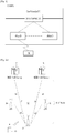
- FIG. 1 is a view schematically illustrating a network structure of an E-UMTS as an exemplary radio communication system.
- An Evolved Universal Mobile Telecommunications System (E-UMTS) is an advanced version of a conventional Universal Mobile Telecommunications System (UMTS) and basic standardization thereof is currently underway in the 3GPP.
- E-UMTS may be generally referred to as a Long Term Evolution (LTE) system.
- LTE Long Term Evolution
- the E-UMTS includes a User Equipment (UE), eNode Bs (eNBs), and an Access Gateway (AG) which is located at an end of the network (E-UTRAN) and connected to an external network.
- the eNBs may simultaneously transmit multiple data streams for a broadcast service, a multicast service, and/or a unicast service.
- One or more cells may exist per eNB.
- the cell is set to operate in one of bandwidths such as 1.25, 2.5, 5, 10, 15, and 20 MHz and provides a downlink (DL) or uplink (UL) transmission service to a plurality of UEs in the bandwidth. Different cells may be set to provide different bandwidths.
- the eNB controls data transmission or reception to and from a plurality of UEs.
- the eNB transmits DL scheduling information of DL data to a corresponding UE so as to inform the UE of a time/frequency domain in which the DL data is supposed to be transmitted, coding, a data size, and hybrid automatic repeat and request (HARQ)-related information.
- HARQ hybrid automatic repeat and request
- the eNB transmits UL scheduling information of UL data to a corresponding UE so as to inform the UE of a time/frequency domain which may be used by the UE, coding, a data size, and HARQ-related information.
- An interface for transmitting user traffic or control traffic may be used between eNBs.
- a core network (CN) may include the AG and a network node or the like for user registration of UEs.
- the AG manages the mobility of a UE on a tracking area (TA) basis.
- One TA includes a plurality of cells.
- WCDMA wideband code division multiple access
- An object of the present invention devised to solve the problem lies in a method and device for transmitting multiplexed HARQ feedbacks in a carrier aggregation system.
- D1 US 2014/349713 A1 ) discusses HARQ feedback when a UE is configured with PUCCH resources. The present invention aims at improving HARQ feedback.
- the technical problems solved by the present invention are not limited to the above technical problems and those skilled in the art may understand other technical problems from the following description.
- the object of the present invention can be achieved by providing a method for a wireless device operating in a wireless communication system as defined by claim 1, by providing a wireless device as defined by claim 4, by providing a method for a base station as defined by claim 7 and by providing a base station as defined by claim 10.
- transmitting multiplexed HARQ feedbacks can efficiently performed in a carrier aggregation system. Specifically, when a UE is configured with PUCCH resources on at least cell other than a special cell, the UE selects one cell with PUCCH resource among all cells with PUCCH resource to transmit the multiplexed HARQ feedbacks on the selected cell.
- Universal mobile telecommunications system is a 3rd Generation (3G) asynchronous mobile communication system operating in wideband code division multiple access (WCDMA) based on European systems, global system for mobile communications (GSM) and general packet radio services (GPRS).
- 3G 3rd Generation
- WCDMA wideband code division multiple access
- GSM global system for mobile communications
- GPRS general packet radio services
- LTE long-term evolution
- 3GPP 3rd generation partnership project
- the 3GPP LTE is a technology for enabling high-speed packet communications. Many schemes have been proposed for the LTE objective including those that aim to reduce user and provider costs, improve service quality, and expand and improve coverage and system capacity.
- the 3G LTE requires reduced cost per bit, increased service availability, flexible use of a frequency band, a simple structure, an open interface, and adequate power consumption of a terminal as an upper-level requirement.
- LTE long term evolution
- LTE-A LTE-advanced
- the embodiments of the present invention are applicable to any other communication system corresponding to the above definition.
- the embodiments of the present invention are described based on a frequency division duplex (FDD) scheme in the present specification, the embodiments of the present invention may be easily modified and applied to a half-duplex FDD (H-FDD) scheme or a time division duplex (TDD) scheme.
- FDD frequency division duplex
- H-FDD half-duplex FDD
- TDD time division duplex
- FIG. 2A is a block diagram illustrating network structure of an evolved universal mobile telecommunication system (E-UMTS).
- E-UMTS may be also referred to as an LTE system.
- the communication network is widely deployed to provide a variety of communication services such as voice (VoIP) through IMS and packet data.
- VoIP voice
- IMS packet data
- the E-UMTS network includes an evolved UMTS terrestrial radio access network (E-UTRAN), an Evolved Packet Core (EPC) and one or more user equipment.
- the E-UTRAN may include one or more evolved NodeB (eNodeB) 20, and a plurality of user equipment (UE) 10 may be located in one cell.
- eNodeB evolved NodeB
- UE user equipment
- MME mobility management entity
- downlink refers to communication from eNodeB 20 to UE 10
- uplink refers to communication from the UE to an eNodeB.
- UE 10 refers to communication equipment carried by a user and may be also referred to as a mobile station (MS), a user terminal (UT), a subscriber station (SS) or a wireless device.
- MS mobile station
- UT user terminal
- SS subscriber station
- FIG. 2B is a block diagram depicting architecture of a typical E-UTRAN and a typical EPC.
- an eNodeB 20 provides end points of a user plane and a control plane to the UE 10.
- MME/SAE gateway 30 provides an end point of a session and mobility management function for UE 10.
- the eNodeB and MME/SAE gateway may be connected via an S1 interface.
- the eNodeB 20 is generally a fixed station that communicates with a UE 10, and may also be referred to as a base station (BS) or an access point.
- BS base station
- One eNodeB 20 may be deployed per cell.
- An interface for transmitting user traffic or control traffic may be used between eNodeBs 20.
- the MME provides various functions including NAS signaling to eNodeBs 20, NAS signaling security, AS Security control, Inter CN node signaling for mobility between 3GPP access networks, Idle mode UE Reachability (including control and execution of paging retransmission), Tracking Area list management (for UE in idle and active mode), PDN GW and Serving GW selection, MME selection for handovers with MME change, SGSN selection for handovers to 2G or 3G 3GPP access networks, Roaming, Authentication, Bearer management functions including dedicated bearer establishment, Support for PWS (which includes ETWS and CMAS) message transmission.
- the SAE gateway host provides assorted functions including Per-user based packet filtering (by e.g.
- MME/SAE gateway 30 will be referred to herein simply as a "gateway,” but it is understood that this entity includes both an MME and an SAE gateway.
- a plurality of nodes may be connected between eNodeB 20 and gateway 30 via the S1 interface.
- the eNodeBs 20 may be connected to each other via an X2 interface and neighboring eNodeBs may have a meshed network structure that has the X2 interface.
- eNodeB 20 may perform functions of selection for gateway 30, routing toward the gateway during a Radio Resource Control (RRC) activation, scheduling and transmitting of paging messages, scheduling and transmitting of Broadcast Channel (BCCH) information, dynamic allocation of resources to UEs 10 in both uplink and downlink, configuration and provisioning of eNodeB measurements, radio bearer control, radio admission control (RAC), and connection mobility control in LTE_ACTIVE state.
- gateway 30 may perform functions of paging origination, LTE-IDLE state management, ciphering of the user plane, System Architecture Evolution (SAE) bearer control, and ciphering and integrity protection of Non-Access Stratum (NAS) signaling.
- SAE System Architecture Evolution
- NAS Non-Access Stratum
- the EPC includes a mobility management entity (MME), a serving-gateway (S-GW), and a packet data network-gateway (PDN-GW).
- MME mobility management entity
- S-GW serving-gateway
- PDN-GW packet data network-gateway
- FIG. 3 is a diagram showing a control plane and a user plane of a radio interface protocol between a UE and an E-UTRAN based on a 3GPP radio access network standard.
- the control plane refers to a path used for transmitting control messages used for managing a call between the UE and the E-UTRAN.
- the user plane refers to a path used for transmitting data generated in an application layer, e.g., voice data or Internet packet data.
- a physical (PHY) layer of a first layer provides an information transfer service to a higher layer using a physical channel.
- the PHY layer is connected to a medium access control (MAC) layer located on the higher layer via a transport channel.
- Data is transported between the MAC layer and the PHY layer via the transport channel.
- Data is transported between a physical layer of a transmitting side and a physical layer of a receiving side via physical channels.
- the physical channels use time and frequency as radio resources.
- the physical channel is modulated using an orthogonal frequency division multiple access (OFDMA) scheme in downlink and is modulated using a single carrier frequency division multiple access (SC-FDMA) scheme in uplink.
- OFDMA orthogonal frequency division multiple access
- SC-FDMA single carrier frequency division multiple access
- the MAC layer of a second layer provides a service to a radio link control (RLC) layer of a higher layer via a logical channel.
- the RLC layer of the second layer supports reliable data transmission.
- a function of the RLC layer may be implemented by a functional block of the MAC layer.
- a packet data convergence protocol (PDCP) layer of the second layer performs a header compression function to reduce unnecessary control information for efficient transmission of an Internet protocol (IP) packet such as an IP version 4 (IPv4) packet or an IP version 6 (IPv6) packet in a radio interface having a relatively small bandwidth.
- IP Internet protocol
- IPv4 IP version 4
- IPv6 IP version 6
- a radio resource control (RRC) layer located at the bottom of a third layer is defined only in the control plane.
- the RRC layer controls logical channels, transport channels, and physical channels in relation to configuration, re-configuration, and release of radio bearers (RBs).
- An RB refers to a service that the second layer provides for data transmission between the UE and the E-UTRAN.
- the RRC layer of the UE and the RRC layer of the E-UTRAN exchange RRC messages with each other.
- One cell of the eNB is set to operate in one of bandwidths such as 1.25, 2.5, 5, 10, 15, and 20 MHz and provides a downlink or uplink transmission service to a plurality of UEs in the bandwidth. Different cells may be set to provide different bandwidths.
- Downlink transport channels for transmission of data from the E-UTRAN to the UE include a broadcast channel (BCH) for transmission of system information, a paging channel (PCH) for transmission of paging messages, and a downlink shared channel (SCH) for transmission of user traffic or control messages.
- BCH broadcast channel
- PCH paging channel
- SCH downlink shared channel
- Traffic or control messages of a downlink multicast or broadcast service may be transmitted through the downlink SCH and may also be transmitted through a separate downlink multicast channel (MCH).
- MCH downlink multicast channel
- Uplink transport channels for transmission of data from the UE to the E-UTRAN include a random access channel (RACH) for transmission of initial control messages and an uplink SCH for transmission of user traffic or control messages.
- Logical channels that are defined above the transport channels and mapped to the transport channels include a broadcast control channel (BCCH), a paging control channel (PCCH), a common control channel (CCCH), a multicast control channel (MCCH), and a multicast traffic channel (MTCH).
- BCCH broadcast control channel
- PCCH paging control channel
- CCCH common control channel
- MCCH multicast control channel
- MTCH multicast traffic channel
- FIG. 4 is a view showing an example of a physical channel structure used in an E-UMTS system.
- a physical channel includes several subframes on a time axis and several subcarriers on a frequency axis.
- one subframe includes a plurality of symbols on the time axis.
- One subframe includes a plurality of resource blocks and one resource block includes a plurality of symbols and a plurality of subcarriers.
- each subframe may use certain subcarriers of certain symbols (e.g., a first symbol) of a subframe for a physical downlink control channel (PDCCH), that is, an L1/L2 control channel.
- PDCCH physical downlink control channel
- an L1/L2 control information transmission area (PDCCH) and a data area (PDSCH) are shown.
- a radio frame of 10 ms is used and one radio frame includes 10 subframes.
- one subframe includes two consecutive slots. The length of one slot may be 0.5 ms.
- one subframe includes a plurality of OFDM symbols and a portion (e.g., a first symbol) of the plurality of OFDM symbols may be used for transmitting the L1/L2 control information.
- a transmission time interval (TTI) which is a unit time for transmitting data is 1ms.
- a base station and a UE mostly transmit/receive data via a PDSCH, which is a physical channel, using a DL-SCH which is a transmission channel, except a certain control signal or certain service data.
- a certain PDCCH is CRC-masked with a radio network temporary identity (RNTI) "A" and information about data is transmitted using a radio resource "B" (e.g., a frequency location) and transmission format information "C" (e.g., a transmission block size, modulation, coding information or the like) via a certain subframe.
- RNTI radio network temporary identity
- C transmission format information
- one or more UEs located in a cell monitor the PDCCH using its RNTI information.
- a specific UE with RNTI "A” reads the PDCCH and then receive the PDSCH indicated by B and C in the PDCCH information.
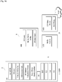
- FIG. 5 is a block diagram of a communication apparatus according to an embodiment of the present invention.
- the apparatus shown in FIG. 5 can be a user equipment (UE) and/or eNB adapted to perform the above mechanism, but it can be any apparatus for performing the same operation.
- UE user equipment
- eNB evolved node B
- the apparatus may comprises a DSP/microprocessor (110) and RF module (transmiceiver; 135).
- the DSP/microprocessor (110) is electrically connected with the transciver (135) and controls it.
- the apparatus may further include power management module (105), battery (155), display (115), keypad (120), SIM card (125), memory device (130), speaker (145) and input device (150), based on its implementation and designer's choice.
- FIG. 5 may represent a UE comprising a receiver (135) configured to receive a request message from a network, and a transmitter (135) configured to transmit the transmission or reception timing information to the network. These receiver and the transmitter can constitute the transceiver (135).
- the UE further comprises a processor (110) connected to the transceiver (135: receiver and transmitter).
- FIG. 5 may represent a network apparatus comprising a transmitter (135) configured to transmit a request message to a UE and a receiver (135) configured to receive the transmission or reception timing information from the UE. These transmitter and receiver may constitute the transceiver (135).
- the network further comprises a processor (110) connected to the transmitter and the receiver. This processor (110) may be configured to calculate latency based on the transmission or reception timing information.
- Proximity-based Service has been discussed in 3GPP.
- the ProSe enables different UEs to be connected (directly) each other (after appropriate procedure(s), such as authentication), through eNB only (but not further through Serving Gateway (SGW) / Packet Data Network Gateway (PDN-GW, PGW)), or through SGW/PGW.
- SGW Serving Gateway
- PDN-GW Packet Data Network Gateway
- PGW Packet Data Network Gateway
- PGW/PGW Packet Data Network Gateway
- Use cases and scenarios are for example: i) Commercial/social use, ii) Network offloading, iii) Public Safety, iv) Integration of current infrastructure services, to assure the consistency of the user experience including reachability and mobility aspects, and v) Public Safety, in case of absence of EUTRAN coverage (subject to regional regulation and operator policy, and limited to specific public-safety designated frequency bands and terminals).
- FIG. 6 is a diagram for carrier aggregation.
- CA Carrier Aggregation
- CCs component carriers
- bandwidth unit e.g. 20 MHz
- LTE system legacy wireless communication system
- Component carriers used for carrier aggregation may be equal to or different from each other in bandwidth size.
- each of the component carriers may have a different frequency band (or center frequency).
- the component carriers may exist on contiguous frequency bands. Yet, component carriers existing on non-contiguous frequency bands may be used for carrier aggregation as well.
- bandwidth sizes of uplink and downlink may be allocated symmetrically or asymmetrically.
- the UE When CA is configured, the UE only has one RRC connection with the network.
- one serving cell At RRC connection establishment/re-establishment/handover, one serving cell provides the NAS mobility information (e.g. TAI), and at RRC connection re-establishment/handover, one serving cell provides the security input.
- This cell is referred to as the Primary Cell (PCell).
- the carrier corresponding to the PCell is the Downlink Primary Component Carrier (DL PCC) while in the uplink it is the Uplink Primary Component Carrier (UL PCC).
- DL PCC Downlink Primary Component Carrier
- UPCC Uplink Primary Component Carrier
- SCells can be configured to form together with the PCell a set of serving cells.
- the carrier corresponding to an SCell is a Downlink Secondary Component Carrier (DL SCC) while in the uplink it is an Uplink Secondary Component Carrier (UL SCC).
- DL SCC Downlink Secondary Component Carrier
- UL SCC Uplink Secondary Component Carrier
- the primary component carrier is the carrier used by a base station to exchange traffic and control signaling with a user equipment.
- the control signaling may include addition of component carrier, setting for primary component carrier, uplink (UL) grant, downlink (DL) assignment and the like.
- a base station may be able to use a plurality of component carriers, a user equipment belonging to the corresponding base station may be set to have one primary component carrier only. If a user equipment operates in a single carrier mode, the primary component carrier is used.
- the primary component carrier should be set to meet all requirements for the data and control signaling exchange between a base station and a user equipment.
- the secondary component carrier may include an additional component carrier that can be activated or deactivated in accordance with a required size of transceived data.
- the secondary component carrier may be set to be used only in accordance with a specific command and rule received from a base station. In order to support an additional bandwidth, the secondary component carrier may be set to be used together with the primary component carrier.
- an activated component carrier such a control signal as a UL grant, a DL assignment and the like can be received by a user equipment from a base station.
- a control signal in UL as a channel quality indicator (CQI), a precoding matrix index (PMI), a rank indicator (RI), a sounding reference signal (SRS) and the like can be transmitted to a base station from a user equipment.
- CQI channel quality indicator
- PMI precoding matrix index
- RI rank indicator
- SRS sounding reference signal
- Resource allocation to a user equipment can have a range of a primary component carrier and a plurality of secondary component carriers.
- a system may be able to allocate secondary component carriers to DL and/or UL asymmetrically.
- the setting of the component carriers may be provided to a user equipment by a base station after RRC connection procedure.
- the RRC connection may mean that a radio resource is allocated to a user equipment based on RRC signaling exchanged between an RRC layer of the user equipment and a network via SRB.
- the user equipment After completion of the RRC connection procedure between the user equipment and the base station, the user equipment may be provided by the base station with the setting information on the primary component carrier and the secondary component carrier.
- the setting information on the secondary component carrier may include addition/deletion (or activation/deactivation) of the secondary component carrier. Therefore, in order to activate a secondary component carrier between a base station and a user equipment or deactivate a previous secondary component carrier, it may be necessary to perform an exchange of RRC signaling and MAC control element.
- the configured set of serving cells for a UE therefore always consists of one PCell and one or more SCells:
- the activation or deactivation of the secondary component carrier may be determined by a base station based on a quality of service (QoS), a load condition of carrier and other factors. And, the base station may be able to instruct a user equipment of secondary component carrier setting using a control message including such information as an indication type (activation/deactivation) for DL/UL, a secondary component carrier list and the like.
- QoS quality of service
- the base station may be able to instruct a user equipment of secondary component carrier setting using a control message including such information as an indication type (activation/deactivation) for DL/UL, a secondary component carrier list and the like.
- RRC reconfiguration, addition and removal of SCells
- RRC can also add, remove, or reconfigure SCells for usage with the target PCell.
- dedicated RRC signalling is used for sending all required system information of the SCell i.e. while in connected mode, UEs need not acquire broadcasted system information directly from the SCells.
- FIG. 7 is a conceptual diagram for Dual Connectivity (DC) between a Master Cell Group (MCS) and a Secondary Cell Group (SCG).
- DC Dual Connectivity
- the Dual Connectivity means that the UE can be connected to both a Master eNode-B (MeNB) and a Secondary eNode-B (SeNB) at the same time.
- the MCG is a group of serving cells associated with the MeNB, comprising of a PCell and optionally one or more SCells.
- the SCG is a group of serving cells associated with the SeNB, comprising of the special SCell and optionally one or more SCells.
- the MeNB is an eNB which terminates at least S1-MME (S1 for the control plane) and the SeNB is an eNB that is providing additional radio resources for the UE but is not the MeNB.
- the Dual Connectivity is a kind of carrier aggregation in that the UE is configured a plurality serving cells. However, unlike all serving cells supporting carrier aggregation of FIG. 6 are served by a same eNB, all serving cells supporting dual connectivity of FIG. 7 are served by different eNBs, respectively at same time. The different eNBs are connected via non-ideal backhaul interface because the UE is connected with the different eNBs at same time.
- DRBs data radio bearers
- SRBs scheduling radio bearers
- the MCG is operated by the MeNB via the frequency of f1
- the SCG is operated by the SeNB via the frequency of f2.
- the frequency f1 and f2 may be equal.
- the backhaul interface (BH) between the MeNB and the SeNB is non-ideal (e.g. X2 interface), which means that there is considerable delay in the backhaul and therefore the centralized scheduling in one node is not possible.
- dedicated RRC signalling is used for sending all required system information of the cell as for CA described above, except for the SFN acquired from MIB of the PSCell of SCG.
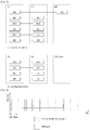
- FIG. 8 is a diagram for MAC structure overview in a UE side.
- the MAC layer handles logical-channel multiplexing, hybrid-ARQ retransmissions, and uplink and downlink scheduling. It is also responsible for multiplexing/demultiplexing data across multiple component carriers when carrier aggregation is used.
- the MAC provides services to the RLC in the form of logical channels.
- a logical channel is defined by the type of information it carries and is generally classified as a control channel, used for transmission of control and configuration information necessary for operating an LTE system, or as a traffic channel, used for the user data.
- the set of logical-channel types specified for LTE includes:
- the MAC layer uses services in the form of transport channels.
- a transport channel is defined by how and with what characteristics the information is transmitted over the radio interface. Data on a transport channel is organized into transport blocks.
- TTI Transmission Time Interval
- MIMO spatial multiplexing
- Transport Format Associated with each transport block is a Transport Format (TF), specifying how the transport block is to be transmitted over the radio interface.
- the transport format includes information about the transport-block size, the modulation-and-coding scheme, and the antenna mapping. By varying the transport format, the MAC layer can thus realize different data rates. Rate control is therefore also known as transport-format selection.
- transport-channel types are defined for LTE:
- Random-Access Channel is also defined as a transport channel, although it does not carry transport blocks.
- each logical channel has its own RLC entity
- the MAC layer handles the corresponding demultiplexing and forwards the RLC PDUs to their respective RLC entity for in-sequence delivery and the other functions handled by the RLC.
- a MAC is used.
- To each RLC PDU there is an associated sub-header in the MAC header.
- the sub-header contains the identity of the logical channel (LCID) from which the RLC PDU originated and the length of the PDU in bytes. There is also a flag indicating whether this is the last sub-header or not.
- the MAC layer can also insert the so-called MAC control elements into the transport blocks to be transmitted over the transport channels.
- a MAC control element is used for inband control signaling?for example, timing-advance commands and random-access response. Control elements are identified with reserved values in the LCID field, where the LCID value indicates the type of control information.
- the length field in the sub-header is removed for control elements with a fixed length.
- the MAC multiplexing functionality is also responsible for handling of multiple component carriers in the case of carrier aggregation.
- the basic principle for carrier aggregation is independent processing of the component carriers in the physical layer, including control signaling, scheduling and hybrid-ARQ retransmissions, while carrier aggregation is invisible to RLC and PDCP.
- Carrier aggregation is therefore mainly seen in the MAC layer, where logical channels, including any MAC control elements, are multiplexed to form one (two in the case of spatial multiplexing) transport block(s) per component carrier with each component carrier having its own hybrid-ARQ entity.
- two MAC entities are configured in the UE: one for the MCG and one for the SCG.
- Each MAC entity is configured by RRC with a serving cell supporting PUCCH transmission and contention based Random Access.
- the term SpCell refers to such cell, whereas the term SCell refers to other serving cells.
- the term SpCell either refers to the PCell of the MCG or the PSCell of the SCG depending on if the MAC entity is associated to the MCG or the SCG, respectively.
- a Timing Advance Group containing the SpCell of a MAC entity is referred to as pTAG, whereas the term sTAG refers to other TAGs.
- the MAC entity shall:
- FIG. 9 is a diagram for an activation/ deactivation MAC control element.
- the network may activate and deactivate the configured SCells.
- the PCell is always activated.
- the network activates and deactivates the SCell(s) by sending the Activation/Deactivation MAC control element.
- the UE maintains a sCellDeactivationTimer timer per configured SCell and deactivates the associated SCell upon its expiry. The same initial timer value applies to each instance of the sCellDeactivationTimer and it is configured by RRC.
- the configured SCells are initially deactivated upon addition and after a handover.
- the UE configures each SCell to each TTI and for each configured SCell:
- HARQ feedback for the MAC PDU containing Activation/Deactivation MAC control element may not be impacted by PCell interruption due to SCell activation/ deactivation.
- the Activation/Deactivation MAC control element is identified by a MAC PDU subheader with LCID as specified in table 1. It has a fixed size and consists of a single octet containing seven C-fields and one R-field.
- the Activation/Deactivation MAC control element is defined as FIG. 9 .
- Ci field indicates the activation/deactivation status of the SCell with SCellIndex i, if there is an SCell configured with SCellIndex i. Else, the UE may ignore the Ci field.
- the Ci field is set to "1" to indicate that the SCell with SCellIndex i shall be activated.
- the Ci field is set to "0" to indicate that the SCell with SCellIndex i shall be de-activated.
- R field is a reserved bit, and set to '0'.
- the sCellDeactivationTimer is a SCell deactivation timer. Value in number of radio frames. Value rf4 corresponds to 4 radio frames, value rf8 corresponds to 8 radio frames and so on. E-UTRAN only configures the field if the UE is configured with one or more SCells other than the PSCell. If the field is absent, the UE shall delete any existing value for this field and assume the value to be set to infinity. The same value applies for each SCell of a Cell Group (i.e. MCG or SCG) (although the associated functionality is performed independently for each SCell).
- MCG Mobility Management Entity
- the UE transmits HARQ feedback on that PUCCH resource by gathering ACK and NACK feedbacks of all configured cells. Note that for the cell in Deactivated state, the UE considers the feedback as NACK.
- a new mechanism is required in consideration of the following aspects: i) How to configure multiple PUCCH resources for a UE, ii) How to multiplex HARQ feedbacks of the cells configured for the UE, and iii)How to transmit the HARQ feedback to the network.
- FIG. 10 is a conceptual diagram for transmitting multiplexed HARQ feedbacks in a carrier aggregation system according to embodiments of the present invention.
- a UE is configured with one PUCCH cell per PUCCH Group, generates a multiplexed HARQ feedback by multiplexing HARQ feedbacks of all HARQ processes of all configured cells belonging to the PUCCH Group, and transmits the multiplexed HARQ feedback on the PUCCH cell of the PUCCH Group.
- the PUCCH Group includes one PUCCH cell and zero or more non-PUCCH cell.
- PUCCH cell refers to a cell configured with PUCCH resource and non-PUCCH cell refers to a cell not configured with PUCCH resource.
- the UE groups a plurality of cells belonging to an enhanced-NodeB (eNB) to a first Physical Uplink Control Channel (PUCCH) group and a second PUCCH group, wherein each of the plurality of cells belongs to one of the first PUCCH group and the second PUCCH group (S1001). And in this case the UE configures a first cell with PUCCH resource in the first PUCCH group and a second cell with PUCCH resource in the second PUCCH group (S1003).
- eNB enhanced-NodeB
- PUCCH Physical Uplink Control Channel
- the first PUCCH group comprises the first cell and zero or more cells without PUCCH resource
- the second PUCCH group comprises the second cell and zero or more cells without PUCCH resource
- the first cell with PUCCH resource is associated with zero or more cells without PUCCH resource in the first PUCCH group
- the second cell with PUCCH resource is associated with zero or more cells without PUCCH resource in the second PUCCH group.
- the UE In a TTI where the HARQ feedback needs to be transmitted for at least one HARQ process of a cell, the UE generates a first Hybrid-ARQ (HARQ) feedback by multiplexing HARQ feedbacks of all HARQ processes of all cells belonging to the first PUCCH group, and generates a second HARQ feedback by multiplexing HARQ feedbacks of all HARQ processes of all cells belonging to the second PUCCH group (S1005).
- HARQ Hybrid-ARQ
- the UE Preferably, only the HARQ process that successfully decodes the received TB generates HARQ feedback as ACK. And all other HARQ processes generate HARQ feedback as NACK. For example, if the HARQ process allocated to the deactivated cell, or if the HARQ process that has not received any TB, or the HARQ process that fails in decoding received TB, the UE considers the HARQ feedback as NACK.
- the UE when the UE multiplexes the HARQ feedbacks of all HARQ processes of all cells belonging to the first PUCCH group, the UE considers HARQ feedback of a HARQ process of a cell belonging to the first PUCCH Group as ACK (Acknowlegdement) if the HARQ process successfully decodes a received TB (Transport Block), and the UE considers HARQ feedback of a HARQ process of a cell belonging to the first PUCCH group as NACK (Negative-Acknowledgement) if the HARQ process is allocated to a deactivated cell, or a HARQ process has not received any TB, or a HARQ process fails in decoding the received TB, and when the UE multiplexes the HARQ feedbacks of all HARQ processes of all cells belonging to the second PUCCH group, the UE considers HARQ feedback of a HARQ process of a cell belonging to the second PUCCH group as ACK if the
- the UE then transmits the first HARQ feedback on the first cell with PUCCH resource and the second HARQ feedback on the second cell with PUCCH resource (S1007).
- FIG. 11 is a conceptual diagram for transmitting multiplexed HARQ feedbacks in a carrier aggregation system according to embodiments of the present invention.
- the UE configure a first cell with PUCCH resource and a second cell with PUCCH resource, wherein the first cell and the second cell belong to an eNB (S1101). And the UE configures zero or more third cells without PUCCH resource, wherein the zero or more third cells without PUCCH resource are associated with one of the first cell and the second cell (S1103).
- PUCCH cell refers to a cell configured with PUCCH resource and non-PUCCH cell refers to a cell not configured with PUCCH resource.
- the first cell and the second cell are PUCCH cell and the zero or more third cells are non-PUCCH cells.
- 'a non-PUCCH cell is associated with (or mapped to) a PUCCH cell', it means that HARQ feedback of the non-PUCCH cell is to be transmitted on the PUCCH cell.
- the UE When the UE configures the first cell, the UE receives an indication indicating which cells of the zero or more third cells without PUCCH resource are to be associated with the first cell. And when the UE configures the second cell also, the UE receives an indication indicating which cells of the zero or more third cells without PUCCH resource are to be associated with the second cell.
- the indication includes PUCCH resource or an indication of non-PUCCH cells mapped to the PUCCH cell.
- the UE When the UE receives the control signaling that configures a PUCCH cell, the UE shall consider that the PUCCH cell and the non-PUCCH cells indicated by the control signaling belong to the PUCCH group that uses the PUCCH cell.
- the UE configures the first cell, if the UE doesn't receive the indication, the first cell is not associated with any of the zero or more third cells.
- the UE When the UE configures a third cell among the zero or more third cells, the UE receives an indication indicating which cell with PUCCH resource is to be associated with the third cell.
- the indication includes PUCCH resource or an indication of a PUCCH cell on which the HARQ feedback of the HARQ processes of the non-PUCCH cell is transmitted.
- the UE When the UE receives the control signaling that configures a non-PUCCH cell, the UE shall consider that the non-PUCCH cell belongs to the PUCCH group that uses the PUCCH cell indicated by the control signaling.
- the UE configures the third cell among the zero or more third cells, if the UE doesn't receive the indication, the UE shall consider that the non-PUCCH cell belongs to a default PUCCH group, e.g. PUCCH group that uses PCell or PSCell. That means the third cell is associated with a Primary-Cell (PCell).
- a default PUCCH group e.g. PUCCH group that uses PCell or PSCell. That means the third cell is associated with a Primary-Cell (PCell).
- PCell Primary-Cell
- the UE generates a first HARQ feedback by multiplexing HARQ feedbacks of all HARQ processes of the first cell and third cells associated with the first cell, and generates a second HARQ feedback by multiplexing HARQ feedbacks of all HARQ processes of the second cell and third cells associated with the second cell (S1105).
- the UE when the UE multiplexes the HARQ feedbacks of all HARQ processes of all cells belonging to the first PUCCH group, the UE considers HARQ feedback of a HARQ process of a cell belonging to the first PUCCH Group as ACK (Acknowlegdement) if the HARQ process successfully decodes a received TB (Transport Block), and the UE considers HARQ feedback of a HARQ process of a cell belonging to the first PUCCH group as NACK (Negative-Acknowledgement) if the HARQ process is allocated to a deactivated cell, or a HARQ process has not received any TB, or a HARQ process fails in decoding the received TB, and when the UE multiplexes the HARQ feedbacks of all HARQ processes of all cells belonging to the second PUCCH group, the UE considers HARQ feedback of a HARQ process of a cell belonging to the second PUCCH group as ACK if the
- the UE then transmits the first HARQ feedback on the first cell with PUCCH resource and the second HARQ feedback on the second cell with PUCCH resource (S1107).
- FIG. 12a and 12b are examples for transmitting multiplexed HARQ feedbacks in a carrier aggregation system according to embodiments of the present invention.
- FIG. 12a is an example for one PUCCH configuration per Group.
- the eNB configures multiple PUCCH cells for a UE by grouping the cells.
- a group hereafter, it is PUCCH Group
- the UE transmits the HARQ feedbacks of all cells within the PUCCH Group via the PUCCH cell.
- UE possibly performs multiple PUCCH transmissions at one point in time.
- RAN2 need to discuss how to indicate the PUCCH Group and the cells belonging to the PUCCH Group, how to modify the PUCCH Group (removal/change of PUCCH Cell), etc. From UE point of view, as there can be multiple PUCCH Groups, multiple PUCCH transmission may occur at the same time. Depending on the number of PUCCH Groups, RAN2 may need to discuss how to support PUCCH transmissions on multiple cells in consideration of e.g., power limitation.
- FIG. 12b is an example for Multiple PUCCH configuration per UE.
- the eNB configures multiple PUCCH cells for a UE.
- the UE transmits the HARQ feedbacks of all cells via one of the PUCCH cells at one point in time.
- the PUCCH Cell which is to be used for HARQ feedback transmission at one point in time can be decided by either the eNB or the UE based on a certain criterion.
- model 1 (case of FIG. 12a ) requires more standardization efforts on procedure/signalling design in order to support removal/change of PUCCH cell of PUCCH group and addition/removal/change of the PUCCH Group.
- model 1 increases the UE complexity in order to support simultaneous PUCCH transmissions on multiple PUCCH Cells with the limited UE power. Given that model 1 would apply to each Cell Group in DC, the number of simultaneous PUCCH transmissions would increase in DC. Then, a careful consideration is required to ensure the successful PUCCH transmission with the limited UE power.
- model 2 (case of FIG.
- model 2 seems to provide more flexible and dynamic PUCCH offloading.
- a specific operation described as performed by the BS may be performed by an upper node of the BS. Namely, it is apparent that, in a network comprised of a plurality of network nodes including a BS, various operations performed for communication with an MS may be performed by the BS, or network nodes other than the BS.
- the term 'eNB' may be replaced with the term 'fixed station', 'Node B', 'Base Station (BS)', 'access point', etc.
- the method according to the embodiments of the present invention may be implemented by one or more Application Specific Integrated Circuits (ASICs), Digital Signal Processors (DSPs), Digital Signal Processing Devices (DSPDs), Programmable Logic Devices (PLDs), Field Programmable Gate Arrays (FPGAs), processors, controllers, microcontrollers, or microprocessors.
- ASICs Application Specific Integrated Circuits
- DSPs Digital Signal Processors
- DSPDs Digital Signal Processing Devices
- PLDs Programmable Logic Devices
- FPGAs Field Programmable Gate Arrays
- processors controllers, microcontrollers, or microprocessors.
- the method according to the embodiments of the present invention may be implemented in the form of modules, procedures, functions, etc. performing the above-described functions or operations.
- Software code may be stored in a memory unit and executed by a processor.
- the memory unit may be located at the interior or exterior of the processor and may transmit and receive data to and from the processor via various known means.
Landscapes
- Engineering & Computer Science (AREA)
- Signal Processing (AREA)
- Computer Networks & Wireless Communication (AREA)
- Mobile Radio Communication Systems (AREA)
Claims (10)
- Verfahren für eine drahtlose Vorrichtung (10), die in einem Drahtloskommunikationssystem arbeitet, wobei das Verfahren aufweist:Empfangen von Konfigurationsinformationen zum Konfigurieren einer nicht-physikalischen Uplink-Steuerkanal-, PUCCH-, Zelle;dadurch gekennzeichnet, dass es aufweist:Übertragen einer hybriden automatischen Wiederholungsanforderungs-, HARQ-, Rückmeldung der Nicht-PUCCH-Zelle auf einer speziellen Zelle, SpCell, oder einer anderen PUCCH-Zelle als der SpCell gemäß einer Anzeigeinformation, wobei die SpCell eine betreuende Zelle ist, welche die PUCCH-Übertragung und Konkurrenz-basierten Direktzugriff unterstützt,wobei die HARQ-Rückmeldung, wenn die Anzeigeinformation nicht mit den Konfigurationsinformationen empfangen wird, auf der SpCell übertragen wird, undwobei die HARQ-Rückmeldung, wenn die Anzeigeinformation mit den Konfigurationsinformationen empfangen wird, auf der PUCCH-Zelle übertragen wird.
- Verfahren nach Anspruch 1, wobei die SpCell eine Primärzelle, PCell, einer Master-Zellengruppe, MCG, oder eine primäre Sekundärzelle, PSCell, einer sekundären Zellengruppe, SCG, ist.
- Verfahren nach Anspruch 1, wobei die Konfigurationsinformationen durch eine Steuersignalisierung von einer Basisstation empfangen werden.
- Drahtlose Vorrichtung (10), die in einem Drahtloskommunikationssystem arbeitet, wobei die drahtlose Vorrichtung aufweist:ein Funkfrequenz-, RF-, Modul (135), undeinen Prozessor (110), der konfiguriert ist, um das RF-Modul zu steuern,wobei der Prozessor konfiguriert ist, um:Konfigurationsinformationen zum Konfigurieren einer nicht-physikalischen Uplink-Steuerkanal-, PUCCH-, Zelle zu empfangen;dadurch gekennzeichnet, dass der Prozessor konfiguriert ist, um:eine hybride automatische Wiederholungsanforderungs-, HARQ-, Rückmeldung der Nicht-PUCCH-Zelle auf einer speziellen Zelle, SpCell, oder einer anderen PUCCH-Zelle als der SpCell gemäß einer Anzeigeinformation zu übertragen, wobei die SpCell eine betreuende Zelle ist, welche die PUCCH-Übertragung und Konkurrenz-basierten Direktzugriff unterstützt,wobei die HARQ-Rückmeldung, wenn die Anzeigeinformation nicht mit den Konfigurationsinformationen empfangen wird, auf der SpCell übertragen wird, undwobei die HARQ-Rückmeldung, wenn die Anzeigeinformation mit den Konfigurationsinformationen empfangen wird, auf der PUCCH-Zelle übertragen wird.
- Drahtlose Vorrichtung nach Anspruch 4, wobei die SpCell eine Primärzelle, PCell, einer Master-Zellengruppe, MCG, oder eine primäre Sekundärzelle, PSCell, einer sekundären Zellengruppe, SCG, ist.
- Drahtlose Vorrichtung nach Anspruch 4, wobei die Konfigurationsinformationen durch eine Steuersignalisierung von einer Basisstation empfangen werden.
- Verfahren für eine Basisstation (20), die in einem Drahtloskommunikationssystem arbeitet, wobei das Verfahren aufweist:Übertragen von Konfigurationsinformationen zum Konfigurieren einer nicht-physikalischen Uplink-Steuerkanal-, PUCCH-, Zelle;dadurch gekennzeichnet, dass es aufweist:Empfangen einer hybriden automatischen Wiederholungsanforderungs-, HARQ-, Rückmeldung der Nicht-PUCCH-Zelle auf einer speziellen Zelle, SpCell, oder einer anderen PUCCH-Zelle als der SpCell gemäß einer Anzeigeinformation, wobei die SpCell eine betreuende Zelle ist, welche die PUCCH-Übertragung und Konkurrenz-basierten Direktzugriff unterstützt,wobei die HARQ-Rückmeldung, wenn die Anzeigeinformation nicht mit den Konfigurationsinformationen übertragen wird, auf der SpCell empfangen wird, undwobei die HARQ-Rückmeldung, wenn die Anzeigeinformation mit den Konfigurationsinformationen übertragen wird, auf der PUCCH-Zelle empfangen wird.
- Verfahren nach Anspruch 7, wobei die SpCell eine Primärzelle, PCell, einer Master-Zellengruppe, MCG, oder eine primäre Sekundärzelle, PSCell, einer sekundären Zellengruppe, SCG, ist.
- Verfahren nach Anspruch 7, wobei die Konfigurationsinformationen durch eine Steuersignalisierung an eine drahtlose Vorrichtung übertragen werden.
- Basisstation, die eingerichtet ist, ein Verfahren nach einem der Ansprüche 7 bis 9 auszuführen.
Applications Claiming Priority (3)
| Application Number | Priority Date | Filing Date | Title |
|---|---|---|---|
| US201562103085P | 2015-01-14 | 2015-01-14 | |
| EP16737540.1A EP3245753B1 (de) | 2015-01-14 | 2016-01-13 | Verfahren zur übertragung von multiplexierten harq-rückkopplungen in einem trägeraggregationssystem und vorrichtung dafür |
| PCT/KR2016/000335 WO2016114576A1 (en) | 2015-01-14 | 2016-01-13 | Method for transmitting multiplexed harq feedbacks in a carrier aggregation system and a device therefor |
Related Parent Applications (1)
| Application Number | Title | Priority Date | Filing Date |
|---|---|---|---|
| EP16737540.1A Division EP3245753B1 (de) | 2015-01-14 | 2016-01-13 | Verfahren zur übertragung von multiplexierten harq-rückkopplungen in einem trägeraggregationssystem und vorrichtung dafür |
Publications (2)
| Publication Number | Publication Date |
|---|---|
| EP3678322A1 EP3678322A1 (de) | 2020-07-08 |
| EP3678322B1 true EP3678322B1 (de) | 2021-08-11 |
Family
ID=56368298
Family Applications (2)
| Application Number | Title | Priority Date | Filing Date |
|---|---|---|---|
| EP16737540.1A Active EP3245753B1 (de) | 2015-01-14 | 2016-01-13 | Verfahren zur übertragung von multiplexierten harq-rückkopplungen in einem trägeraggregationssystem und vorrichtung dafür |
| EP20159551.9A Active EP3678322B1 (de) | 2015-01-14 | 2016-01-13 | Verfahren zur übertragung von multiplexierten harq-rückkopplungen in einem trägeraggregationssystem und vorrichtung dafür |
Family Applications Before (1)
| Application Number | Title | Priority Date | Filing Date |
|---|---|---|---|
| EP16737540.1A Active EP3245753B1 (de) | 2015-01-14 | 2016-01-13 | Verfahren zur übertragung von multiplexierten harq-rückkopplungen in einem trägeraggregationssystem und vorrichtung dafür |
Country Status (6)
| Country | Link |
|---|---|
| US (5) | US10014984B2 (de) |
| EP (2) | EP3245753B1 (de) |
| JP (2) | JP6789952B2 (de) |
| CN (2) | CN112152768B (de) |
| ES (2) | ES2898341T3 (de) |
| WO (1) | WO2016114576A1 (de) |
Families Citing this family (33)
| Publication number | Priority date | Publication date | Assignee | Title |
|---|---|---|---|---|
| US10014984B2 (en) | 2015-01-14 | 2018-07-03 | Lg Electronics Inc. | Method for transmitting multiplexed HARQ feedbacks in a carrier aggregation system and a device therefor |
| US10187184B2 (en) * | 2015-01-14 | 2019-01-22 | Lg Electronics Inc. | Method for transmitting multiplexed HARQ feedbacks in a carrier aggregation system and a device therefor |
| CN106063349B (zh) * | 2015-01-29 | 2019-12-24 | 华为技术有限公司 | Pucch配置方法和装置 |
| US10284354B2 (en) * | 2015-01-30 | 2019-05-07 | Nokia Solutions And Networks Oy | Methods, apparatus, computer program, computer program product and mobile communications network for serving cells comprising primary cell and secondary cells |
| EP3266267B1 (de) * | 2015-03-06 | 2022-04-27 | Samsung Electronics Co., Ltd. | Verfahren und vorrichtung zum durchführen und meldung von messungen über ein benutzerendgerät mit mehrträgerkonfiguration in mobilkommunikationssystemen |
| US10334490B2 (en) * | 2015-03-10 | 2019-06-25 | Deutsche Telekom Ag | Overall network performance and/or overall quality of service of a mobile communication network by assigning a physical cell identifier information to a plurality of radio cells |
| US10447367B2 (en) * | 2015-03-16 | 2019-10-15 | Ofinno, Llc | Channel state information transmission in a wireless device and wireless network |
| JP6595113B2 (ja) * | 2015-08-21 | 2019-10-23 | エルジー エレクトロニクス インコーポレイティド | 無線通信システムにおいてセルを活性化又は非活性化するための方法及びそのための装置 |
| US10200164B2 (en) | 2015-09-22 | 2019-02-05 | Comcast Cable Communications, Llc | Carrier activation in a multi-carrier wireless network |
| US10172124B2 (en) | 2015-09-22 | 2019-01-01 | Comcast Cable Communications, Llc | Carrier selection in a multi-carrier wireless network |
| CA3000508C (en) | 2015-10-17 | 2019-01-22 | Ofinno Technologies, Llc | Control channel configuration in partial and full subframes |
| US10548121B2 (en) | 2016-02-03 | 2020-01-28 | Comcast Cable Communications, Llc | Downlink and uplink channel transmission and monitoring in a wireless network |
| US10880921B2 (en) | 2016-02-04 | 2020-12-29 | Comcast Cable Communications, Llc | Detection threshold for a wireless network |
| US10582443B2 (en) | 2016-03-25 | 2020-03-03 | Comcast Cable Communications, Llc | Vehicle wireless device discovery |
| US10965479B2 (en) | 2016-04-02 | 2021-03-30 | Comcast Cable Communications, Llc | Bearer modification for V2X communications |
| US10200992B2 (en) | 2016-05-06 | 2019-02-05 | Comcast Cable Communications, Llc | Uplink signal starting position in a wireless device and wireless network |
| US11057925B2 (en) * | 2016-08-07 | 2021-07-06 | Comcast Cable Communications, Llc | Deactivation timer in a wireless device and wireless network |
| US10687319B2 (en) | 2016-08-08 | 2020-06-16 | Comcast Cable Communications, Llc | Group power control for a secondary cell |
| US11147062B2 (en) | 2016-10-14 | 2021-10-12 | Comcast Cable Communications, Llc | Dual connectivity power control for wireless network and wireless device |
| US20180124831A1 (en) | 2016-10-29 | 2018-05-03 | Ofinno Technologies, Llc | Dual connectivity scheduling request for wireless network and wireless device |
| US10848977B2 (en) | 2016-11-02 | 2020-11-24 | Comcast Cable Communications, Llc | Dual connectivity with licensed assisted access |
| US10959218B2 (en) | 2016-11-14 | 2021-03-23 | Comcast Cable Communications, Llc | Semi-persistent scheduling confirmation |
| CN110235397A (zh) * | 2016-12-01 | 2019-09-13 | 瑞典爱立信有限公司 | 下行链路harq反馈传输 |
| EP4040712B1 (de) * | 2017-05-05 | 2023-09-06 | Apple Inc. | Bandbreitenteilkonfiguration und betrieb für new radio (nr)-breitbandbenutzergeräte |
| EP3695540B1 (de) * | 2017-10-10 | 2023-06-28 | Telefonaktiebolaget LM Ericsson (publ) | Änderung einer ressource mit physischem uplink-steuerkanal (pucch) |
| WO2019153139A1 (zh) * | 2018-02-07 | 2019-08-15 | Oppo广东移动通信有限公司 | 无线链路失败处理方法及相关产品 |
| US11284396B2 (en) | 2018-03-19 | 2022-03-22 | Qualcomm Incorporated | Techniques for determining beams for beamforming wireless communications |
| EP3771232B1 (de) | 2018-03-28 | 2023-08-16 | Beijing Xiaomi Mobile Software Co., Ltd. | Informationsmeldungs- und konfigurationsverfahren und vorrichtung, benutzergerät und basisstation |
| CN114157400B (zh) * | 2019-02-15 | 2024-04-16 | 华为技术有限公司 | 一种码本的处理方法及装置 |
| US11812314B2 (en) * | 2020-05-20 | 2023-11-07 | Qualcomm Incorporated | Dynamic switching between carrier aggregation and multi-connectivity |
| CN115811387A (zh) * | 2021-09-14 | 2023-03-17 | 中国移动通信有限公司研究院 | 通信方法、装置、通信设备及存储介质 |
| KR20230064419A (ko) * | 2021-11-03 | 2023-05-10 | 삼성전자주식회사 | 무선 통신 시스템에서 셀 스위칭에 기반한 제어 정보 송수신 방법 및 장치 |
| CN116938295A (zh) * | 2022-04-02 | 2023-10-24 | 上海朗帛通信技术有限公司 | 一种被用于无线通信的通信节点中的方法和装置 |
Family Cites Families (15)
| Publication number | Priority date | Publication date | Assignee | Title |
|---|---|---|---|---|
| US8571939B2 (en) | 2010-07-07 | 2013-10-29 | Toshiba Global Commerce Solutions Holdings Corporation | Two phase payment link and authorization for mobile devices |
| WO2012011775A2 (ko) * | 2010-07-22 | 2012-01-26 | 엘지전자 주식회사 | 다중 반송파 시스템에서 상향링크 제어 정보 전송 방법 및 장치 |
| EP2673903B1 (de) * | 2011-03-18 | 2018-05-02 | LG Electronics Inc. | Verfahren zur übertragung von steuerungsinformationen in einem drahtlosen kommunikationssystem und vorrichtung dafür |
| US8837304B2 (en) * | 2011-04-08 | 2014-09-16 | Sharp Kabushiki Kaisha | Devices for multi-group communications |
| US9225503B2 (en) * | 2011-05-02 | 2015-12-29 | Lg Electronics Inc. | Method for transmitting/receiving data in wireless communication system and base station for same |
| US9749992B2 (en) * | 2011-08-10 | 2017-08-29 | Interdigital Patent Holdings, Inc. | Uplink feedback for multi-site scheduling |
| CN103795508A (zh) * | 2012-11-02 | 2014-05-14 | 北京三星通信技术研究有限公司 | Harq-ack反馈信息的传输方法及ue |
| CN105075146B (zh) * | 2013-01-07 | 2019-03-01 | 三星电子株式会社 | 用于增强型节点b间载波聚合的方法和装置 |
| WO2014109568A1 (en) * | 2013-01-11 | 2014-07-17 | Lg Electronics Inc. | Method and apparatus for transmitting uplink control signals in wireless communication system |
| CN104079390A (zh) * | 2013-03-25 | 2014-10-01 | 北京三星通信技术研究有限公司 | 跨基站载波聚合系统中传输harq-ack反馈信息的方法及设备 |
| US9426785B2 (en) * | 2013-05-20 | 2016-08-23 | Nokia Technologies Oy | Contiguous intra-band carrier aggregation (CA), PUCCH, and quasi-contiguous uplink resource allocation |
| KR102124889B1 (ko) * | 2014-03-07 | 2020-06-19 | 후아웨이 테크놀러지 컴퍼니 리미티드 | 단말간 통신을 지원하는 무선통신 시스템에서 매체접근제어 정보 전송 방법 및 장치 |
| US10014984B2 (en) * | 2015-01-14 | 2018-07-03 | Lg Electronics Inc. | Method for transmitting multiplexed HARQ feedbacks in a carrier aggregation system and a device therefor |
| CN107925971B (zh) * | 2015-08-05 | 2022-01-18 | 夏普株式会社 | 终端装置、基站装置、通信方法以及集成电路 |
| US20220272659A1 (en) * | 2021-02-25 | 2022-08-25 | Samsung Electronics Co., Ltd. | Method and apparatus for monitoring paging occasion in a wireless communication system |
-
2016
- 2016-01-13 US US14/994,600 patent/US10014984B2/en active Active
- 2016-01-13 CN CN202010831481.6A patent/CN112152768B/zh active Active
- 2016-01-13 EP EP16737540.1A patent/EP3245753B1/de active Active
- 2016-01-13 ES ES20159551T patent/ES2898341T3/es active Active
- 2016-01-13 ES ES16737540T patent/ES2797806T3/es active Active
- 2016-01-13 EP EP20159551.9A patent/EP3678322B1/de active Active
- 2016-01-13 JP JP2017537454A patent/JP6789952B2/ja active Active
- 2016-01-13 CN CN201680005712.XA patent/CN107210888B/zh active Active
- 2016-01-13 WO PCT/KR2016/000335 patent/WO2016114576A1/en active Application Filing
-
2018
- 2018-06-25 US US16/017,666 patent/US10615921B2/en active Active
-
2020
- 2020-02-19 US US16/794,714 patent/US11057160B2/en active Active
- 2020-07-29 US US16/942,183 patent/US11057162B2/en active Active
- 2020-11-04 JP JP2020184386A patent/JP7029512B2/ja active Active
-
2021
- 2021-06-16 US US17/349,510 patent/US11750331B2/en active Active
Non-Patent Citations (1)
| Title |
|---|
| None * |
Also Published As
| Publication number | Publication date |
|---|---|
| JP2021022949A (ja) | 2021-02-18 |
| CN112152768A (zh) | 2020-12-29 |
| US20180309545A1 (en) | 2018-10-25 |
| US20200358561A1 (en) | 2020-11-12 |
| US10014984B2 (en) | 2018-07-03 |
| EP3245753A4 (de) | 2018-10-31 |
| JP2018506223A (ja) | 2018-03-01 |
| US20160204905A1 (en) | 2016-07-14 |
| JP7029512B2 (ja) | 2022-03-03 |
| US11057162B2 (en) | 2021-07-06 |
| US11750331B2 (en) | 2023-09-05 |
| ES2898341T3 (es) | 2022-03-07 |
| EP3245753B1 (de) | 2020-03-25 |
| US20210314096A1 (en) | 2021-10-07 |
| US10615921B2 (en) | 2020-04-07 |
| EP3678322A1 (de) | 2020-07-08 |
| JP6789952B2 (ja) | 2020-11-25 |
| WO2016114576A1 (en) | 2016-07-21 |
| CN107210888B (zh) | 2020-09-08 |
| US11057160B2 (en) | 2021-07-06 |
| ES2797806T3 (es) | 2020-12-03 |
| US20200186295A1 (en) | 2020-06-11 |
| EP3245753A1 (de) | 2017-11-22 |
| CN112152768B (zh) | 2023-06-23 |
| CN107210888A (zh) | 2017-09-26 |
Similar Documents
| Publication | Publication Date | Title |
|---|---|---|
| US11750331B2 (en) | Method for transmitting multiplexed HARQ feedbacks in a carrier aggregation system and a device therefor | |
| US10159076B2 (en) | Method for de-configuring a cell from PUCCH resource in a carrier aggregation system and a device therefor | |
| EP3245757B1 (de) | Verfahren und vorrichtung zur konfiguration einer zelle aus einer pucch-ressource in einem trägeraggregationssystem und vorrichtung dafür | |
| US10321442B2 (en) | Method for configuring an activated SCell with PUCCH resource in a carrier aggregation system and a device therefor | |
| US10362563B2 (en) | Method for deactivating SCells upon a TAT expiry for PUCCH cell in a carrier aggregation system and a device therefor | |
| US10237858B2 (en) | Method for de-configuring a cell from PUCCH resource in a carrier aggregation system and a device therefor | |
| US10200160B2 (en) | Method for transmitting multiplexed HARQ feedbacks in a carrier aggregation system and a device therefor | |
| US20180020444A1 (en) | Method for applying a new pucch configuration in a carrier aggregation system and a device therefor | |
| US10187184B2 (en) | Method for transmitting multiplexed HARQ feedbacks in a carrier aggregation system and a device therefor | |
| US10687369B2 (en) | Method for initiating a random access procedure in a carrier aggregation system and a device therefor | |
| US10034312B2 (en) | Method for initiating a random access procedure in a carrier aggregation system and a device therefor | |
| EP3245758B1 (de) | Verfahren zum entfernen einer letzten pucch-ressource einer pucch-gruppe in einem trägeraggregationssystem und vorrichtung dafür | |
| EP3245829B1 (de) | Verfahren zur konfiguration einer zelle aus einer pucch-ressource in einem trägeraggregationssystem und vorrichtung dafür | |
| US10321443B2 (en) | Method for performing a PUCCH transmission on a deactivated PUCCH SCell in a carrier aggregation system and a device therefor | |
| US20180007640A1 (en) | Method for performing power scaling for pucch transmission in a carrier aggregation system and a device therefor | |
| US20170366306A1 (en) | Method for selecting pucch transmission in a carrier aggregation system and a device therefor | |
| US20170373805A1 (en) | Method for performing a pucch transmission on a pucch cell in a carrier aggregation system and a device therefor |
Legal Events
| Date | Code | Title | Description |
|---|---|---|---|
| PUAI | Public reference made under article 153(3) epc to a published international application that has entered the european phase |
Free format text: ORIGINAL CODE: 0009012 |
|
| STAA | Information on the status of an ep patent application or granted ep patent |
Free format text: STATUS: THE APPLICATION HAS BEEN PUBLISHED |
|
| AC | Divisional application: reference to earlier application |
Ref document number: 3245753 Country of ref document: EP Kind code of ref document: P |
|
| AK | Designated contracting states |
Kind code of ref document: A1 Designated state(s): AL AT BE BG CH CY CZ DE DK EE ES FI FR GB GR HR HU IE IS IT LI LT LU LV MC MK MT NL NO PL PT RO RS SE SI SK SM TR |
|
| STAA | Information on the status of an ep patent application or granted ep patent |
Free format text: STATUS: REQUEST FOR EXAMINATION WAS MADE |
|
| 17P | Request for examination filed |
Effective date: 20200727 |
|
| RBV | Designated contracting states (corrected) |
Designated state(s): AL AT BE BG CH CY CZ DE DK EE ES FI FR GB GR HR HU IE IS IT LI LT LU LV MC MK MT NL NO PL PT RO RS SE SI SK SM TR |
|
| GRAP | Despatch of communication of intention to grant a patent |
Free format text: ORIGINAL CODE: EPIDOSNIGR1 |
|
| STAA | Information on the status of an ep patent application or granted ep patent |
Free format text: STATUS: GRANT OF PATENT IS INTENDED |
|
| INTG | Intention to grant announced |
Effective date: 20201118 |
|
| GRAJ | Information related to disapproval of communication of intention to grant by the applicant or resumption of examination proceedings by the epo deleted |
Free format text: ORIGINAL CODE: EPIDOSDIGR1 |
|
| STAA | Information on the status of an ep patent application or granted ep patent |
Free format text: STATUS: REQUEST FOR EXAMINATION WAS MADE |
|
| GRAP | Despatch of communication of intention to grant a patent |
Free format text: ORIGINAL CODE: EPIDOSNIGR1 |
|
| INTC | Intention to grant announced (deleted) | ||
| STAA | Information on the status of an ep patent application or granted ep patent |
Free format text: STATUS: GRANT OF PATENT IS INTENDED |
|
| INTG | Intention to grant announced |
Effective date: 20210311 |
|
| RIN1 | Information on inventor provided before grant (corrected) |
Inventor name: YI, SEUNGJUNE Inventor name: LEE, SUNYOUNG |
|
| GRAS | Grant fee paid |
Free format text: ORIGINAL CODE: EPIDOSNIGR3 |
|
| GRAA | (expected) grant |
Free format text: ORIGINAL CODE: 0009210 |
|
| STAA | Information on the status of an ep patent application or granted ep patent |
Free format text: STATUS: THE PATENT HAS BEEN GRANTED |
|
| AC | Divisional application: reference to earlier application |
Ref document number: 3245753 Country of ref document: EP Kind code of ref document: P |
|
| AK | Designated contracting states |
Kind code of ref document: B1 Designated state(s): AL AT BE BG CH CY CZ DE DK EE ES FI FR GB GR HR HU IE IS IT LI LT LU LV MC MK MT NL NO PL PT RO RS SE SI SK SM TR |
|
| REG | Reference to a national code |
Ref country code: CH Ref legal event code: EP |
|
| REG | Reference to a national code |
Ref country code: DE Ref legal event code: R096 Ref document number: 602016062275 Country of ref document: DE |
|
| REG | Reference to a national code |
Ref country code: IE Ref legal event code: FG4D Ref country code: AT Ref legal event code: REF Ref document number: 1420487 Country of ref document: AT Kind code of ref document: T Effective date: 20210915 |
|
| REG | Reference to a national code |
Ref country code: NL Ref legal event code: FP |
|
| REG | Reference to a national code |
Ref country code: LT Ref legal event code: MG9D |
|
| REG | Reference to a national code |
Ref country code: AT Ref legal event code: MK05 Ref document number: 1420487 Country of ref document: AT Kind code of ref document: T Effective date: 20210811 |
|
| PG25 | Lapsed in a contracting state [announced via postgrant information from national office to epo] |
Ref country code: RS Free format text: LAPSE BECAUSE OF FAILURE TO SUBMIT A TRANSLATION OF THE DESCRIPTION OR TO PAY THE FEE WITHIN THE PRESCRIBED TIME-LIMIT Effective date: 20210811 Ref country code: SE Free format text: LAPSE BECAUSE OF FAILURE TO SUBMIT A TRANSLATION OF THE DESCRIPTION OR TO PAY THE FEE WITHIN THE PRESCRIBED TIME-LIMIT Effective date: 20210811 Ref country code: LT Free format text: LAPSE BECAUSE OF FAILURE TO SUBMIT A TRANSLATION OF THE DESCRIPTION OR TO PAY THE FEE WITHIN THE PRESCRIBED TIME-LIMIT Effective date: 20210811 Ref country code: AT Free format text: LAPSE BECAUSE OF FAILURE TO SUBMIT A TRANSLATION OF THE DESCRIPTION OR TO PAY THE FEE WITHIN THE PRESCRIBED TIME-LIMIT Effective date: 20210811 Ref country code: BG Free format text: LAPSE BECAUSE OF FAILURE TO SUBMIT A TRANSLATION OF THE DESCRIPTION OR TO PAY THE FEE WITHIN THE PRESCRIBED TIME-LIMIT Effective date: 20211111 Ref country code: FI Free format text: LAPSE BECAUSE OF FAILURE TO SUBMIT A TRANSLATION OF THE DESCRIPTION OR TO PAY THE FEE WITHIN THE PRESCRIBED TIME-LIMIT Effective date: 20210811 Ref country code: HR Free format text: LAPSE BECAUSE OF FAILURE TO SUBMIT A TRANSLATION OF THE DESCRIPTION OR TO PAY THE FEE WITHIN THE PRESCRIBED TIME-LIMIT Effective date: 20210811 Ref country code: NO Free format text: LAPSE BECAUSE OF FAILURE TO SUBMIT A TRANSLATION OF THE DESCRIPTION OR TO PAY THE FEE WITHIN THE PRESCRIBED TIME-LIMIT Effective date: 20211111 Ref country code: PT Free format text: LAPSE BECAUSE OF FAILURE TO SUBMIT A TRANSLATION OF THE DESCRIPTION OR TO PAY THE FEE WITHIN THE PRESCRIBED TIME-LIMIT Effective date: 20211213 |
|
| PG25 | Lapsed in a contracting state [announced via postgrant information from national office to epo] |
Ref country code: PL Free format text: LAPSE BECAUSE OF FAILURE TO SUBMIT A TRANSLATION OF THE DESCRIPTION OR TO PAY THE FEE WITHIN THE PRESCRIBED TIME-LIMIT Effective date: 20210811 Ref country code: LV Free format text: LAPSE BECAUSE OF FAILURE TO SUBMIT A TRANSLATION OF THE DESCRIPTION OR TO PAY THE FEE WITHIN THE PRESCRIBED TIME-LIMIT Effective date: 20210811 Ref country code: GR Free format text: LAPSE BECAUSE OF FAILURE TO SUBMIT A TRANSLATION OF THE DESCRIPTION OR TO PAY THE FEE WITHIN THE PRESCRIBED TIME-LIMIT Effective date: 20211112 |
|
| REG | Reference to a national code |
Ref country code: ES Ref legal event code: FG2A Ref document number: 2898341 Country of ref document: ES Kind code of ref document: T3 Effective date: 20220307 |
|
| PG25 | Lapsed in a contracting state [announced via postgrant information from national office to epo] |
Ref country code: DK Free format text: LAPSE BECAUSE OF FAILURE TO SUBMIT A TRANSLATION OF THE DESCRIPTION OR TO PAY THE FEE WITHIN THE PRESCRIBED TIME-LIMIT Effective date: 20210811 |
|
| REG | Reference to a national code |
Ref country code: DE Ref legal event code: R097 Ref document number: 602016062275 Country of ref document: DE |
|
| PG25 | Lapsed in a contracting state [announced via postgrant information from national office to epo] |
Ref country code: SM Free format text: LAPSE BECAUSE OF FAILURE TO SUBMIT A TRANSLATION OF THE DESCRIPTION OR TO PAY THE FEE WITHIN THE PRESCRIBED TIME-LIMIT Effective date: 20210811 Ref country code: SK Free format text: LAPSE BECAUSE OF FAILURE TO SUBMIT A TRANSLATION OF THE DESCRIPTION OR TO PAY THE FEE WITHIN THE PRESCRIBED TIME-LIMIT Effective date: 20210811 Ref country code: RO Free format text: LAPSE BECAUSE OF FAILURE TO SUBMIT A TRANSLATION OF THE DESCRIPTION OR TO PAY THE FEE WITHIN THE PRESCRIBED TIME-LIMIT Effective date: 20210811 Ref country code: EE Free format text: LAPSE BECAUSE OF FAILURE TO SUBMIT A TRANSLATION OF THE DESCRIPTION OR TO PAY THE FEE WITHIN THE PRESCRIBED TIME-LIMIT Effective date: 20210811 Ref country code: CZ Free format text: LAPSE BECAUSE OF FAILURE TO SUBMIT A TRANSLATION OF THE DESCRIPTION OR TO PAY THE FEE WITHIN THE PRESCRIBED TIME-LIMIT Effective date: 20210811 Ref country code: AL Free format text: LAPSE BECAUSE OF FAILURE TO SUBMIT A TRANSLATION OF THE DESCRIPTION OR TO PAY THE FEE WITHIN THE PRESCRIBED TIME-LIMIT Effective date: 20210811 |
|
| PLBE | No opposition filed within time limit |
Free format text: ORIGINAL CODE: 0009261 |
|
| STAA | Information on the status of an ep patent application or granted ep patent |
Free format text: STATUS: NO OPPOSITION FILED WITHIN TIME LIMIT |
|
| 26N | No opposition filed |
Effective date: 20220512 |
|
| PG25 | Lapsed in a contracting state [announced via postgrant information from national office to epo] |
Ref country code: IT Free format text: LAPSE BECAUSE OF FAILURE TO SUBMIT A TRANSLATION OF THE DESCRIPTION OR TO PAY THE FEE WITHIN THE PRESCRIBED TIME-LIMIT Effective date: 20210811 |
|
| PG25 | Lapsed in a contracting state [announced via postgrant information from national office to epo] |
Ref country code: SI Free format text: LAPSE BECAUSE OF FAILURE TO SUBMIT A TRANSLATION OF THE DESCRIPTION OR TO PAY THE FEE WITHIN THE PRESCRIBED TIME-LIMIT Effective date: 20210811 Ref country code: MC Free format text: LAPSE BECAUSE OF FAILURE TO SUBMIT A TRANSLATION OF THE DESCRIPTION OR TO PAY THE FEE WITHIN THE PRESCRIBED TIME-LIMIT Effective date: 20210811 |
|
| REG | Reference to a national code |
Ref country code: CH Ref legal event code: PL |
|
| REG | Reference to a national code |
Ref country code: BE Ref legal event code: MM Effective date: 20220131 |
|
| PG25 | Lapsed in a contracting state [announced via postgrant information from national office to epo] |
Ref country code: LU Free format text: LAPSE BECAUSE OF NON-PAYMENT OF DUE FEES Effective date: 20220113 |
|
| PG25 | Lapsed in a contracting state [announced via postgrant information from national office to epo] |
Ref country code: BE Free format text: LAPSE BECAUSE OF NON-PAYMENT OF DUE FEES Effective date: 20220131 |
|
| PG25 | Lapsed in a contracting state [announced via postgrant information from national office to epo] |
Ref country code: LI Free format text: LAPSE BECAUSE OF NON-PAYMENT OF DUE FEES Effective date: 20220131 Ref country code: CH Free format text: LAPSE BECAUSE OF NON-PAYMENT OF DUE FEES Effective date: 20220131 |
|
| PG25 | Lapsed in a contracting state [announced via postgrant information from national office to epo] |
Ref country code: IE Free format text: LAPSE BECAUSE OF NON-PAYMENT OF DUE FEES Effective date: 20220113 |
|
| PGFP | Annual fee paid to national office [announced via postgrant information from national office to epo] |
Ref country code: ES Payment date: 20230227 Year of fee payment: 8 |
|
| PGFP | Annual fee paid to national office [announced via postgrant information from national office to epo] |
Ref country code: DE Payment date: 20221205 Year of fee payment: 8 |
|
| P01 | Opt-out of the competence of the unified patent court (upc) registered |
Effective date: 20230527 |
|
| PGFP | Annual fee paid to national office [announced via postgrant information from national office to epo] |
Ref country code: GB Payment date: 20231207 Year of fee payment: 9 |
|
| PGFP | Annual fee paid to national office [announced via postgrant information from national office to epo] |
Ref country code: NL Payment date: 20231206 Year of fee payment: 9 Ref country code: FR Payment date: 20231206 Year of fee payment: 9 |
|
| PGFP | Annual fee paid to national office [announced via postgrant information from national office to epo] |
Ref country code: ES Payment date: 20240222 Year of fee payment: 9 |
|
| PG25 | Lapsed in a contracting state [announced via postgrant information from national office to epo] |
Ref country code: MK Free format text: LAPSE BECAUSE OF FAILURE TO SUBMIT A TRANSLATION OF THE DESCRIPTION OR TO PAY THE FEE WITHIN THE PRESCRIBED TIME-LIMIT Effective date: 20210811 Ref country code: CY Free format text: LAPSE BECAUSE OF FAILURE TO SUBMIT A TRANSLATION OF THE DESCRIPTION OR TO PAY THE FEE WITHIN THE PRESCRIBED TIME-LIMIT Effective date: 20210811 |
|
| PGFP | Annual fee paid to national office [announced via postgrant information from national office to epo] |
Ref country code: DE Payment date: 20231205 Year of fee payment: 9 |