EP3678278A1 - Charging station with high frequency distribution network - Google Patents
Charging station with high frequency distribution network Download PDFInfo
- Publication number
- EP3678278A1 EP3678278A1 EP19150044.6A EP19150044A EP3678278A1 EP 3678278 A1 EP3678278 A1 EP 3678278A1 EP 19150044 A EP19150044 A EP 19150044A EP 3678278 A1 EP3678278 A1 EP 3678278A1
- Authority
- EP
- European Patent Office
- Prior art keywords
- converter
- charging station
- voltage
- central part
- distribution network
- Prior art date
- Legal status (The legal status is an assumption and is not a legal conclusion. Google has not performed a legal analysis and makes no representation as to the accuracy of the status listed.)
- Granted
Links
Images






Classifications
-
- H—ELECTRICITY
- H02—GENERATION; CONVERSION OR DISTRIBUTION OF ELECTRIC POWER
- H02J—ELECTRIC POWER NETWORKS; CIRCUIT ARRANGEMENTS OR SYSTEMS FOR SUPPLYING OR DISTRIBUTING ELECTRIC POWER; SYSTEMS FOR STORING ELECTRIC ENERGY
- H02J3/00—Circuit arrangements for AC mains or AC distribution networks
- H02J3/34—Arrangements for transfer of electric power between networks of substantially different frequency
-
- B—PERFORMING OPERATIONS; TRANSPORTING
- B60—VEHICLES IN GENERAL
- B60L—PROPULSION OF ELECTRICALLY-PROPELLED VEHICLES; SUPPLYING ELECTRIC POWER FOR AUXILIARY EQUIPMENT OF ELECTRICALLY-PROPELLED VEHICLES; ELECTRODYNAMIC BRAKE SYSTEMS FOR VEHICLES IN GENERAL; MAGNETIC SUSPENSION OR LEVITATION FOR VEHICLES; MONITORING OPERATING VARIABLES OF ELECTRICALLY-PROPELLED VEHICLES; ELECTRIC SAFETY DEVICES FOR ELECTRICALLY-PROPELLED VEHICLES
- B60L53/00—Methods of charging batteries, specially adapted for electric vehicles; Charging stations or on-board charging equipment therefor; Exchange of energy storage elements in electric vehicles
- B60L53/10—Methods of charging batteries, specially adapted for electric vehicles; Charging stations or on-board charging equipment therefor; Exchange of energy storage elements in electric vehicles characterised by the energy transfer between the charging station and the vehicle
- B60L53/12—Inductive energy transfer
- B60L53/122—Circuits or methods for driving the primary coil, e.g. supplying electric power to the coil
-
- B—PERFORMING OPERATIONS; TRANSPORTING
- B60—VEHICLES IN GENERAL
- B60L—PROPULSION OF ELECTRICALLY-PROPELLED VEHICLES; SUPPLYING ELECTRIC POWER FOR AUXILIARY EQUIPMENT OF ELECTRICALLY-PROPELLED VEHICLES; ELECTRODYNAMIC BRAKE SYSTEMS FOR VEHICLES IN GENERAL; MAGNETIC SUSPENSION OR LEVITATION FOR VEHICLES; MONITORING OPERATING VARIABLES OF ELECTRICALLY-PROPELLED VEHICLES; ELECTRIC SAFETY DEVICES FOR ELECTRICALLY-PROPELLED VEHICLES
- B60L53/00—Methods of charging batteries, specially adapted for electric vehicles; Charging stations or on-board charging equipment therefor; Exchange of energy storage elements in electric vehicles
- B60L53/30—Constructional details of charging stations
-
- B—PERFORMING OPERATIONS; TRANSPORTING
- B60—VEHICLES IN GENERAL
- B60L—PROPULSION OF ELECTRICALLY-PROPELLED VEHICLES; SUPPLYING ELECTRIC POWER FOR AUXILIARY EQUIPMENT OF ELECTRICALLY-PROPELLED VEHICLES; ELECTRODYNAMIC BRAKE SYSTEMS FOR VEHICLES IN GENERAL; MAGNETIC SUSPENSION OR LEVITATION FOR VEHICLES; MONITORING OPERATING VARIABLES OF ELECTRICALLY-PROPELLED VEHICLES; ELECTRIC SAFETY DEVICES FOR ELECTRICALLY-PROPELLED VEHICLES
- B60L2210/00—Converter types
- B60L2210/10—DC to DC converters
-
- B—PERFORMING OPERATIONS; TRANSPORTING
- B60—VEHICLES IN GENERAL
- B60L—PROPULSION OF ELECTRICALLY-PROPELLED VEHICLES; SUPPLYING ELECTRIC POWER FOR AUXILIARY EQUIPMENT OF ELECTRICALLY-PROPELLED VEHICLES; ELECTRODYNAMIC BRAKE SYSTEMS FOR VEHICLES IN GENERAL; MAGNETIC SUSPENSION OR LEVITATION FOR VEHICLES; MONITORING OPERATING VARIABLES OF ELECTRICALLY-PROPELLED VEHICLES; ELECTRIC SAFETY DEVICES FOR ELECTRICALLY-PROPELLED VEHICLES
- B60L2210/00—Converter types
- B60L2210/30—AC to DC converters
-
- B—PERFORMING OPERATIONS; TRANSPORTING
- B60—VEHICLES IN GENERAL
- B60L—PROPULSION OF ELECTRICALLY-PROPELLED VEHICLES; SUPPLYING ELECTRIC POWER FOR AUXILIARY EQUIPMENT OF ELECTRICALLY-PROPELLED VEHICLES; ELECTRODYNAMIC BRAKE SYSTEMS FOR VEHICLES IN GENERAL; MAGNETIC SUSPENSION OR LEVITATION FOR VEHICLES; MONITORING OPERATING VARIABLES OF ELECTRICALLY-PROPELLED VEHICLES; ELECTRIC SAFETY DEVICES FOR ELECTRICALLY-PROPELLED VEHICLES
- B60L2210/00—Converter types
- B60L2210/40—DC to AC converters
- B60L2210/42—Voltage source inverters
-
- H—ELECTRICITY
- H02—GENERATION; CONVERSION OR DISTRIBUTION OF ELECTRIC POWER
- H02J—ELECTRIC POWER NETWORKS; CIRCUIT ARRANGEMENTS OR SYSTEMS FOR SUPPLYING OR DISTRIBUTING ELECTRIC POWER; SYSTEMS FOR STORING ELECTRIC ENERGY
- H02J2105/00—Networks for supplying or distributing electric power characterised by their spatial reach or by the load
- H02J2105/30—Networks for supplying or distributing electric power characterised by their spatial reach or by the load the load networks being external to vehicles, i.e. exchanging power with vehicles
- H02J2105/33—Networks for supplying or distributing electric power characterised by their spatial reach or by the load the load networks being external to vehicles, i.e. exchanging power with vehicles exchanging power with road vehicles
- H02J2105/37—Networks for supplying or distributing electric power characterised by their spatial reach or by the load the load networks being external to vehicles, i.e. exchanging power with vehicles exchanging power with road vehicles exchanging power with electric vehicles [EV] or with hybrid electric vehicles [HEV]
-
- H—ELECTRICITY
- H02—GENERATION; CONVERSION OR DISTRIBUTION OF ELECTRIC POWER
- H02J—ELECTRIC POWER NETWORKS; CIRCUIT ARRANGEMENTS OR SYSTEMS FOR SUPPLYING OR DISTRIBUTING ELECTRIC POWER; SYSTEMS FOR STORING ELECTRIC ENERGY
- H02J4/00—Circuit arrangements for mains or distribution networks not specified as AC or DC; Circuit arrangements for mains or distribution networks combining AC and DC sections or sub-networks
-
- H—ELECTRICITY
- H02—GENERATION; CONVERSION OR DISTRIBUTION OF ELECTRIC POWER
- H02J—ELECTRIC POWER NETWORKS; CIRCUIT ARRANGEMENTS OR SYSTEMS FOR SUPPLYING OR DISTRIBUTING ELECTRIC POWER; SYSTEMS FOR STORING ELECTRIC ENERGY
- H02J50/00—Circuit arrangements or systems for wireless supply or distribution of electric power
- H02J50/10—Circuit arrangements or systems for wireless supply or distribution of electric power using inductive coupling
- H02J50/12—Circuit arrangements or systems for wireless supply or distribution of electric power using inductive coupling of the resonant type
-
- H—ELECTRICITY
- H02—GENERATION; CONVERSION OR DISTRIBUTION OF ELECTRIC POWER
- H02J—ELECTRIC POWER NETWORKS; CIRCUIT ARRANGEMENTS OR SYSTEMS FOR SUPPLYING OR DISTRIBUTING ELECTRIC POWER; SYSTEMS FOR STORING ELECTRIC ENERGY
- H02J7/00—Circuit arrangements for charging or discharging batteries or for supplying loads from batteries
- H02J7/50—Circuit arrangements for charging or discharging batteries or for supplying loads from batteries acting upon multiple batteries simultaneously or sequentially
-
- Y—GENERAL TAGGING OF NEW TECHNOLOGICAL DEVELOPMENTS; GENERAL TAGGING OF CROSS-SECTIONAL TECHNOLOGIES SPANNING OVER SEVERAL SECTIONS OF THE IPC; TECHNICAL SUBJECTS COVERED BY FORMER USPC CROSS-REFERENCE ART COLLECTIONS [XRACs] AND DIGESTS
- Y02—TECHNOLOGIES OR APPLICATIONS FOR MITIGATION OR ADAPTATION AGAINST CLIMATE CHANGE
- Y02T—CLIMATE CHANGE MITIGATION TECHNOLOGIES RELATED TO TRANSPORTATION
- Y02T10/00—Road transport of goods or passengers
- Y02T10/60—Other road transportation technologies with climate change mitigation effect
- Y02T10/70—Energy storage systems for electromobility, e.g. batteries
-
- Y—GENERAL TAGGING OF NEW TECHNOLOGICAL DEVELOPMENTS; GENERAL TAGGING OF CROSS-SECTIONAL TECHNOLOGIES SPANNING OVER SEVERAL SECTIONS OF THE IPC; TECHNICAL SUBJECTS COVERED BY FORMER USPC CROSS-REFERENCE ART COLLECTIONS [XRACs] AND DIGESTS
- Y02—TECHNOLOGIES OR APPLICATIONS FOR MITIGATION OR ADAPTATION AGAINST CLIMATE CHANGE
- Y02T—CLIMATE CHANGE MITIGATION TECHNOLOGIES RELATED TO TRANSPORTATION
- Y02T10/00—Road transport of goods or passengers
- Y02T10/60—Other road transportation technologies with climate change mitigation effect
- Y02T10/7072—Electromobility specific charging systems or methods for batteries, ultracapacitors, supercapacitors or double-layer capacitors
-
- Y—GENERAL TAGGING OF NEW TECHNOLOGICAL DEVELOPMENTS; GENERAL TAGGING OF CROSS-SECTIONAL TECHNOLOGIES SPANNING OVER SEVERAL SECTIONS OF THE IPC; TECHNICAL SUBJECTS COVERED BY FORMER USPC CROSS-REFERENCE ART COLLECTIONS [XRACs] AND DIGESTS
- Y02—TECHNOLOGIES OR APPLICATIONS FOR MITIGATION OR ADAPTATION AGAINST CLIMATE CHANGE
- Y02T—CLIMATE CHANGE MITIGATION TECHNOLOGIES RELATED TO TRANSPORTATION
- Y02T90/00—Enabling technologies or technologies with a potential or indirect contribution to GHG emissions mitigation
- Y02T90/10—Technologies relating to charging of electric vehicles
- Y02T90/12—Electric charging stations
-
- Y—GENERAL TAGGING OF NEW TECHNOLOGICAL DEVELOPMENTS; GENERAL TAGGING OF CROSS-SECTIONAL TECHNOLOGIES SPANNING OVER SEVERAL SECTIONS OF THE IPC; TECHNICAL SUBJECTS COVERED BY FORMER USPC CROSS-REFERENCE ART COLLECTIONS [XRACs] AND DIGESTS
- Y02—TECHNOLOGIES OR APPLICATIONS FOR MITIGATION OR ADAPTATION AGAINST CLIMATE CHANGE
- Y02T—CLIMATE CHANGE MITIGATION TECHNOLOGIES RELATED TO TRANSPORTATION
- Y02T90/00—Enabling technologies or technologies with a potential or indirect contribution to GHG emissions mitigation
- Y02T90/10—Technologies relating to charging of electric vehicles
- Y02T90/14—Plug-in electric vehicles
Definitions
- the invention relates to a charging station for electric vehicles.
- a low frequency transformer may be used to provide an isolation in the charging pole between a car and the grid for safety purpose.
- bulky transformers for conventional 50 Hz based distribution network usually require a large foot print of the charging station.
- the invention relates to a charging station for electric vehicles.
- An electrical vehicle may be a means of transportation on land, in water or air, which comprises a drive being supplied with electrical energy. This energy may be stored on batteries that are charged by the charging station.
- an electrical vehicle may be a car, bus, motorcycle, ship, airplane, etc.
- the charging station comprises a central part for converting a grid AC voltage from an electrical grid into a high frequency AC voltage, an (AC) distribution network for distributing the high frequency AC voltage, and a plurality of coils directly connected to the distribution network, wherein each coil is adapted for transferring energy to an electrical vehicle.
- the charging station may incorporate further interconnection with additional storage and/or renewable energy sources.
- the charging station may also provide grid support to the electrical grid to meet grid codes.
- the central part may comprise a housing, in which components, such as converters and a transformer are housed. It may be that the central part comprises components that are remote from each other, i.e. that the central part is a distributed system.
- the central part may be connected to an electrical grid.
- the frequency of the grid AC voltage may be less than 100 Hz, such as 50 Hz or 60 Hz.
- the grid AC voltage may be a medium voltage of more than 3 kV, for example in the range from 3.3 kV to 20 kV.
- the high frequency AC voltage may have a frequency of more than 10 times the frequency of the grid AC voltage.
- the frequency of the high frequency AC voltage is more than 400 Hz, for example more than 10 kHz.
- the high frequency AC voltage may be a low voltage, such as a voltage of less than 3 kV, for example in a range between 230 V to 690 V.
- Every coil which is connected to the distribution network, may be a primary coil of a transformer, for example of a charging pole and/or a coil for wireless power transfer via an air gap.
- the distribution network may be a two-phase network, which interconnects the coils with the central part. It may be that the coils are arranged remote from the central part, such as more than 10 m remote from the central part.
- the distribution network may connect the coils in parallel, for example it may have the form of a distribution bus.
- the distribution network may have lines, which interconnect a housing of the central part and housings, in which the coils are arranged, such as a housing of a charging pole or a housing of a ground coil for wireless power transfer.
- the distribution network is solely provided inside an housing of the charging station and/or its central part.
- converters for converting the high frequency AC voltage into a DC voltage are provided in this housing, which then may be distributed to charging poles.
- the charging pole may include just a control panel and/or a DC-to-DC converter, to control the charging rate of a battery, and/or components such as fuses, disconnectors and breakers.
- the power density of the charging station can be increased, since all inductive components connected to the high frequency distribution network can be decreased in size.
- Such inductors comprise transformers and coils.
- the power electronic converter of a charging pole may be become simpler, more efficient, and more reliable, because the number of power stage may be reduced.
- the central part may be modular and/or may comprise at least two converter units, which may be connected in series and/or in parallel with their inputs.
- the interconnection of the converter units may be chosen in dependence of the power to be processed and/or the level of their input voltage.
- the central part comprises a transformer at its output side connected to the distribution network.
- the transformer may be a high frequency transformer, which may be less bulky than a low frequency transformer.
- the central part comprises an AC-to-AC matrix type converter.
- the electrical converter of the central part may be implemented with solely one transformer.
- a medium voltage DC grid is available as a backbone to support an AC electrical grid.
- the charging station may be implemented just with one DC-to-AC converter.
- the central part comprises at least two transformers having secondary coils connected in parallel to the distribution network.
- the primary sides of the transformers may be connected to different converter units of the central part.
- the central part comprises a grid side AC-to-DC converter for receiving the grid voltage and at least one network side DC-to-AC converter, which are interconnected via a DC link.
- Both converters may be active converters, i.e. may have controllable switches. Both converters may be interconnected with a DC link, which may comprise a capacitor.
- the network side converter may be a modular converter and/or may comprise at least two converter units, which may result in easy power scaling.
- the converter units may be connected in parallel with their input sides to the DC link. It also may be possible that the converter units are connected in series with their input sides and that each converter unit is connected in parallel to a section of a split DC link.
- the one or more output transformers of the central part may be interconnected between the DC-to-AC converter and/or the converter units and the distribution network.
- the central part comprises at least two DC-to-AC converters which are connected to the DC link via a DC distribution network.
- the DC-to-AC converters may be remote from each other and/or from the AC-to-DC converter.
- the AC-to-DC converter and the DC-to-AC converters may be interconnected with a DC distribution network.
- the DC distribution network may have lines, which can have a length of more than 10 m. It may be that power is transferred via the DC distribution network to reduce a line length in the AC distribution network.
- Every DC-to-AC converter may have one or more converter units and/or one or more output transformers as described above and below. Every DC-to-AC converter may be interconnected with a different high frequency AC distribution network, such as described above and below.
- both converters may be accommodated in one housing and/or may be near to each other.
- the DC-to-AC converter is composed of at least one converter unit, which is one of neutral point clamped type, T type, flying cap type and modular multi-level converter type.
- the DC-to-AC converter is composed of at least two converter units, which are connected in series with their inputs.
- the converter units may be of the types as described above and below.
- Each of the series converter units may be connected to a section of a split DC link.
- the split DC link may comprise two or more series-connected capacitors. Every capacitor may provide a section of the split DC link.
- the DC-to-AC converter is composed of at least two converter units, which are connected in parallel with their inputs.
- the converter units may be of the types as described above and below. With a parallel connection, the power to be processed may be increased.
- two converter units such as two converter units of the DC-to-AC converter, are connected with their outputs via a primary coil of a transformer of the central part.
- the two converter units may have to be switched to generate opposite output voltages.
- the charging system may comprise a resonant tank.
- a resonant tank may comprise a capacitor and an inductor.
- a resonant tank may increase high power conversion efficiency and/or may lower conduction losses in the distribution network.
- a resonant tank may result in a softer switching for a rectifier inside a charging pole connected to the distribution network.
- the usage of a resonant tank may result in good cross-regulation characteristics for multiple outputs (such as charging poles or wireless energy transfer coils).
- open loop operation for the central charging station converter may be implemented.
- the resonant tank is connected in the distribution network.
- the resonant tank is connected between a transformer of the central part and the coils.
- the resonant tank may be connected between an output of the central part and the coils supplied by the distribution network.
- the resonant tank may be connected to a secondary side of the one or more output transformers of the central part.
- the resonant tank is connected between a converter unit of the central part and a transformer of the central part.
- the resonant tank may be connected to a primary side of the one or more output transformers of the central part. It may be that every output transformer has a resonant tank of its own on its primary side.
- the distribution network may be used to supply high frequency coils, which are used for transferring power to the electric vehicles without galvanic coupling.
- such a coil may be the primary coil of a transformer integrated into a charging pole.
- a transformer may be a high frequency transformer.
- the charging pole furthermore may comprise one or more converters for converting the high frequency AC voltage into a charging DC voltage for charging an electric vehicle.
- the charging pole comprises an AC-to-DC converter for receiving a voltage from the transformer, wherein the AC-to-DC converter of the charging pole supplies a DC-to-DC converter for generating a charging voltage.
- the charging poles may be also interconnected to the distribution network in parallel to increase the charging capability or charging rate for the battery.
- a coil connected to the distribution network is a coil for wireless energy transfer via an air gap.
- a coil may be a ground coil, over which an electric vehicle with a corresponding coil may be parked and charged.
- moving electric vehicles may be charged with such coils, which may be placed inside a street.
- Fig. 1 shows a charging station 10, which comprises a central part 12 and a plurality of charging poles 14, which are interconnected with the central part 12 via a high frequency AC distribution network 16.
- the central part 12 is connected with an electrical grid 18, which may be three-phase, and the AC distribution network 16, which may be single-phase.
- the central part 12 converts a medium voltage from the grid 18 of for example 3.3 kV to 20 kV into a low voltage of for example 230 V to 690 V, which is supplied to the distribution network 16.
- the input voltage from the electrical grid 18 may have a frequency of 50 Hz or 60 Hz.
- the frequency of the voltage in the AC distribution network 16 may be a high frequency of more than 400 Hz, for example more than 10 kHz.
- the central part 12 may be composed of an AC-to-DC converter 20 and a DC-to-AC converter 22, which are interconnected via a DC link 21.
- the central part 12 may comprise a direct AC-to-AC converter, which may have a single-stage structure, for example by utilizing a matrix-type converter topology.
- a medium voltage active or passive rectifier such as a multi-pulse rectifier with diodes or thyristors may be used.
- the AC-to-DC converter 20 also may be a multilevel converter and/or a modular multilevel converter.
- the DC-to-AC converter 22 may be a multilevel converter and/or a modular multilevel converter.
- the DC-to-AC converter 22 may be composed of several converter units as will be described below in more detail.
- a charging pole 14 comprise a transformer 24, which is directly connected with its primary coil 26 with the AC distribution network 16.
- An AC-to-DC converter 30, such as a passive diode rectifier, is connected to a secondary coil 28 of the transformer 24. It also may be that the AC-to-DC converter is an active rectifier.
- a charging pole 14 also may comprise a DC-to-DC converter 32, for example a buck/boost-converter, which is supplied by the AC-to-DC converter 30. To the DC-to-DC converter 32 or to the AC-to-DC converter 30, an electric vehicle may be connected for charging.
- the components 20, 22 of the central part 12 may be provided in one housing and/or building.
- the components 20, 22 of the central part 12 also may be distributed into several housings and/or buildings. It also may be possible that at least two DC-to-AC converters 22, such as the ones as described with respect to Fig. 1 , are connected to the DC link provided by the AC-to-DC converter 20.
- the AC-to-DC converter 20 and the at least two DC-to-AC converters 22 may be interconnected with a DC distribution network 34.
- the DC voltage in the DC distribution network 34 may be medium voltage, for example between 3.3 kV and 20 kV.
- a single low voltage high frequency AC distribution network 16 may lead to large conduction losses in the AC distribution network 16.
- the intermediate DC distribution network 34 may be included. That is, a medium DC voltage, which is available by rectifying a medium voltage AC voltage with the AC-to-DC converter 20, may be used for distribution to reduce long distance conduction losses.
- the charging station 10 and its central part 12 may be divided into several sub-charging areas and each sub-charging area may be equipped with a DC-to-AC converter 22, which may convert the medium DC voltage into a low voltage high frequency AC voltage for local distribution.
- Fig. 3 shows a charging station 10, for example as in Fig. 1 , where the charging poles 14 have been replaced with coils 36 for wireless power transfer.
- coils 36 may be provided in a ground below a parking place of an electric vehicle 38 or in a street.
- a high frequency AC distribution network 16 may be used as a primary side for a wireless power transfer to moving vehicles 38. In this case, by installing the high frequency AC distribution network 16 along a roadway, even moving electric vehicles 38 may be charged.
- a secondary coil 37 of the electric vehicle 38 may couple via a magnetic field with the primary coil 36 (for example via an air gap).
- the electric vehicle 38 itself then may have an AC-to-DC converter 30 and optionally a DC-to-DC converter 32 as described with respect to Fig. 1 and/or as described below.
- wireless power transfer coils 36 as described with respect to Fig. 3 may be combined with the charging station 10 of Fig. 1 , where, for example, some of the charging poles 14 may be replaced with such coils 36. It also may be possible that some or all of the charging poles 14 of Fig. 2 connected to one DC-to-AC converter 22 are replaced with coils 36 for wireless power transfer.
- a renewable energy source such as a photo voltaic power generation station, and/or a battery storage system may be directly connected to the high frequency AC distribution network 16 and/or the DC distribution network 34.
- the renewable energy source and/or the battery storage may be connected to the high frequency AC distribution network 16 via an AC-to-DC converter, analogous to the converter 22.
- the renewable energy source and/or the battery storage may be connected to the DC distribution network 34 via a DC-to-DC converter.
- This DC-to-DC converter also may be of a modular type.
- the power rating of the central part 12 may be smaller as the sum of the power ratings of the charging poles 14 and/or the coils 36, when it is assumed that only some of the charging poles 14 and/or coils 36 are used for charging.
- the charging station 10 may have three charging poles 14 and the power rating of an individual charging pole may be 300 kW. Since it is very rare that all the charging poles 14 are in operation at the same time, the power rating of the central part 12 may be designed lower than the maximum required power. For example, even though the total power rating of all charging poles 14 is 900 kW, the central part 12 may be designed with a power rating of 600 kW or even of 300 kW. The total installed power rating of power electronics may be reduced with the high frequency AC distribution network supplying more than one charging pole 14 and/or coil 36.
- Fig. 4 shows a DC-to-AC converter 22 that may be used in the charging stations 10 as shown in Fig. 1 to 3 .
- the DC-to-AC converter 22 comprises a DC link 21 with a capacitor 39, a converter unit 40 connected in parallel with its inputs 42 to the DC link 21 and a transformer 46, which is connected with its primary coil 48 to an output 44 of the converter unit 40.
- the secondary coil 50 of the transformer 46 is connected to the high frequency AC distribution network 16.
- a DC blocking capacitor 52 may be interconnected between the output 44 and the primary coil 48.
- two or more converter units 40 may be connected in series with their input 42. Every one of these converter units 40 may be connected in parallel to a capacitor 39 of a split DC link 21, which is composed of series-connected capacitors 39.
- the outputs 44 of two converter units 40 may be connected via the primary coil 48 of the transformer 46 with each other.
- two or more converter units 40 may be connected in parallel with their inputs 42 and in parallel to the DC link 21.
- the outputs 44 of two converter units 40 may be connected via the primary coil 48 of the transformer 46 with each other.
- Fig. 7 to 8 show possible topologies for the converter units 40 as shown in Fig. 4 to 6 and below.
- Fig. 7 to 9 show converter units 40, which comprise 4 series-connected semiconductor switches 54, which are interconnected between the inputs 42. At the middle point, the switches 54 provide the output 44. Every converter unit 40 may comprise and/or may be interconnected with a DC link 56, which may comprise one or more series-connected capacitors 58.
- Fig. 7 is a neutral point clamped converter unit 40, in which two intermediate middle points between two upper und two lower switches 54 are connected via diodes 60 with a middle point of a split DC link 56.
- Fig. 8 is a T-type converter unit 40, where the middle point between the switches 54 providing the output 44 is interconnected via two anti-series-connected switches 62 with the middle point of the split DC link 56.
- Fig. 9 is a flying capacitor type converter unit 40, where two intermediate middle points between two upper und two lower switches 54 are connected via a capacitor 64 with each other.
- Fig. 10 shows a modular multi-level converter unit 40, which comprises a plurality of series-connected converter modules 66, which are interconnected between the inputs 42.
- the output 44 is provided at a middle point between the converter modules 66.
- Every converter module 66 may comprise a converter bridge 68 composed of two switches 70 and a capacitor 72 connected in parallel to the converter bridge 68.
- Fig. 11 and Fig. 12 show two further examples of a DC-to-AC converter 22.
- a plurality of converter units 40 (here 4) are connected in series with their inputs 42. Every one of these converter units 40 is connected in parallel to a capacitor 39 of a split DC link 21, which is composed of series-connected capacitors 39.
- every converter unit 22 is associated with one transformer 46.
- the output 44 of every converter unit 22 is connected via the primary coil of the transformer 46 with one of its inputs 42. All transformers 46 are connected in parallel with their secondary coils.
- two converter units 22 are associated with one transformer 46.
- the output 44 of a first converter unit 22 is connected via the primary coil of the respective transformer 46 with the output 44 of a second converter unit 22.
- the transformers 46 are connected in parallel with their secondary coils.
- Fig. 13 and Fig. 14 show further examples of charging stations, where a resonant tank 74 is provided in the high frequency section. Resonant operation may be used for the high frequency AC distribution network 16.
- the resonant tank 74 may comprise a resonant capacitor 76 and a resonant inductor 78 and/or may be used to make the current waveform in the distribution network 16 more of sinusoidal shape. With a resonant operation, a soft switching for the converter units 40 of the DC-to-AC converter 22 may be achieved.
- one way to implement the resonant operation is inserting the resonant tank 74 directly in the distribution network 16.
- the resonant tank 74 may be connected between the one or more transformers 46 of the central part 12 and the transformers 24 of the charging poles 14 (and/or the coils 36 for wireless power transfer).
- one or more resonant tanks 74 may be connected between the output 44 of a converter unit 40 and the transformer 46.
- a resonant tank 74 may be provided for every transformer 46.
- the DC blocking capacitor 52 and a leakage inductance 78 of the transformer 46 may be used for the resonant tank 74.
- Fig. 14 furthermore shows an exemplary overall circuit diagram of a charging station 10.
- the AC-to-DC converter 20 of the central part 12 comprises a modular multi-level converter as shown in Fig. 10 , which is composed of converter modules 66 as shown in Fig. 10 .
- These modular multi-level converters are connected in parallel to the DC link 21.
- the AC-to-DC converter 20 of the central part 12 may be of any type of rectifier stage.
- a modular converter and/or the converter types as shown in Fig. 7 to 10 may be used.
- the high frequency AC distribution network 16 in particular in combination with a modular DC-to-AC converter 22 of the central part 12 of the charging station 10 may result in a small foot print and high power density for the high frequency transformers 46, 24.
- An easy scaling with respect to the medium voltage provided by the grid 18 is possible due to the modularity of the DC-to-AC converter 22.
- the power rating of the central part 12 may be reduced and the solution is compatible with the interconnection of renewable energy source and an energy storage for grid support and micro-grid functionalities.
Landscapes
- Engineering & Computer Science (AREA)
- Power Engineering (AREA)
- Transportation (AREA)
- Mechanical Engineering (AREA)
- Charge And Discharge Circuits For Batteries Or The Like (AREA)
Abstract
Description
- The invention relates to a charging station for electric vehicles.
- With increasing number of electric vehicles, the importance of charging stations for these vehicles is growing. It is foreseen that in the future the charging requirement of a car will be higher than 350 kW. Since the total power consumption of a charging station may reach multi-megawatt, the power density of a distribution network of the charging station becomes more and more important.
- At these power levels, it is common to utilize a low frequency transformer to step down the voltage from a medium voltage AC grid. Furthermore, a low frequency transformer may be used to provide an isolation in the charging pole between a car and the grid for safety purpose. However, bulky transformers for conventional 50 Hz based distribution network usually require a large foot print of the charging station.
- It is an objective of the invention to reduce the foot print and the costs of a charging station. It is a further objective of the invention to increase the power density of a charging station.
- These objectives are achieved by the subject-matter of the independent claims. Further exemplary embodiments are evident from the dependent claims and the following description.
- The invention relates to a charging station for electric vehicles. An electrical vehicle may be a means of transportation on land, in water or air, which comprises a drive being supplied with electrical energy. This energy may be stored on batteries that are charged by the charging station.
- For example, an electrical vehicle may be a car, bus, motorcycle, ship, airplane, etc.
- According to an embodiment of the invention, the charging station comprises a central part for converting a grid AC voltage from an electrical grid into a high frequency AC voltage, an (AC) distribution network for distributing the high frequency AC voltage, and a plurality of coils directly connected to the distribution network, wherein each coil is adapted for transferring energy to an electrical vehicle.
- For grid friendly operation, the charging station may incorporate further interconnection with additional storage and/or renewable energy sources. The charging station may also provide grid support to the electrical grid to meet grid codes.
- The central part may comprise a housing, in which components, such as converters and a transformer are housed. It may be that the central part comprises components that are remote from each other, i.e. that the central part is a distributed system.
- The central part may be connected to an electrical grid. The frequency of the grid AC voltage may be less than 100 Hz, such as 50 Hz or 60 Hz. The grid AC voltage may be a medium voltage of more than 3 kV, for example in the range from 3.3 kV to 20 kV.
- The high frequency AC voltage may have a frequency of more than 10 times the frequency of the grid AC voltage. For example, the frequency of the high frequency AC voltage is more than 400 Hz, for example more than 10 kHz. The high frequency AC voltage may be a low voltage, such as a voltage of less than 3 kV, for example in a range between 230 V to 690 V.
- Every coil, which is connected to the distribution network, may be a primary coil of a transformer, for example of a charging pole and/or a coil for wireless power transfer via an air gap.
- The distribution network may be a two-phase network, which interconnects the coils with the central part. It may be that the coils are arranged remote from the central part, such as more than 10 m remote from the central part. The distribution network may connect the coils in parallel, for example it may have the form of a distribution bus. The distribution network may have lines, which interconnect a housing of the central part and housings, in which the coils are arranged, such as a housing of a charging pole or a housing of a ground coil for wireless power transfer.
- It is also may be possible that the distribution network is solely provided inside an housing of the charging station and/or its central part. In this case it may be that converters for converting the high frequency AC voltage into a DC voltage are provided in this housing, which then may be distributed to charging poles. As a result, the charging pole may include just a control panel and/or a DC-to-DC converter, to control the charging rate of a battery, and/or components such as fuses, disconnectors and breakers.
- By providing a central part and a high frequency distribution network, the power density of the charging station can be increased, since all inductive components connected to the high frequency distribution network can be decreased in size. Such inductors comprise transformers and coils.
- With high frequency low voltage distribution, the power electronic converter of a charging pole may be become simpler, more efficient, and more reliable, because the number of power stage may be reduced.
- It has to be noted that the central part may be modular and/or may comprise at least two converter units, which may be connected in series and/or in parallel with their inputs. The interconnection of the converter units may be chosen in dependence of the power to be processed and/or the level of their input voltage.
- According to an embodiment of the invention, the central part comprises a transformer at its output side connected to the distribution network. The transformer may be a high frequency transformer, which may be less bulky than a low frequency transformer.
- It is possible that the central part comprises an AC-to-AC matrix type converter. In this case, the electrical converter of the central part may be implemented with solely one transformer. It also may be possible that a medium voltage DC grid is available as a backbone to support an AC electrical grid. In this case, the charging station may be implemented just with one DC-to-AC converter.
- According to an embodiment of the invention, the central part comprises at least two transformers having secondary coils connected in parallel to the distribution network. The primary sides of the transformers may be connected to different converter units of the central part.
- According to an embodiment of the invention, the central part comprises a grid side AC-to-DC converter for receiving the grid voltage and at least one network side DC-to-AC converter, which are interconnected via a DC link. Both converters may be active converters, i.e. may have controllable switches. Both converters may be interconnected with a DC link, which may comprise a capacitor.
- The network side converter may be a modular converter and/or may comprise at least two converter units, which may result in easy power scaling. The converter units may be connected in parallel with their input sides to the DC link. It also may be possible that the converter units are connected in series with their input sides and that each converter unit is connected in parallel to a section of a split DC link.
- The one or more output transformers of the central part may be interconnected between the DC-to-AC converter and/or the converter units and the distribution network.
- According to an embodiment of the invention, the central part comprises at least two DC-to-AC converters which are connected to the DC link via a DC distribution network.
- The DC-to-AC converters may be remote from each other and/or from the AC-to-DC converter. The AC-to-DC converter and the DC-to-AC converters may be interconnected with a DC distribution network. The DC distribution network may have lines, which can have a length of more than 10 m. It may be that power is transferred via the DC distribution network to reduce a line length in the AC distribution network.
- Every DC-to-AC converter may have one or more converter units and/or one or more output transformers as described above and below. Every DC-to-AC converter may be interconnected with a different high frequency AC distribution network, such as described above and below.
- In the case of one AC-to-DC converter and one DC-to-AC converter of the central part, both converters may be accommodated in one housing and/or may be near to each other.
- According to an embodiment of the invention, the DC-to-AC converter is composed of at least one converter unit, which is one of neutral point clamped type, T type, flying cap type and modular multi-level converter type.
- According to an embodiment of the invention, the DC-to-AC converter is composed of at least two converter units, which are connected in series with their inputs. The converter units may be of the types as described above and below. Each of the series converter units may be connected to a section of a split DC link. The split DC link may comprise two or more series-connected capacitors. Every capacitor may provide a section of the split DC link.
- According to an embodiment of the invention, the DC-to-AC converter is composed of at least two converter units, which are connected in parallel with their inputs. Again, the converter units may be of the types as described above and below. With a parallel connection, the power to be processed may be increased.
- According to an embodiment of the invention, two converter units, such as two converter units of the DC-to-AC converter, are connected with their outputs via a primary coil of a transformer of the central part. Thus, the two converter units may have to be switched to generate opposite output voltages.
- According to an embodiment of the invention, the charging system may comprise a resonant tank. Such a resonant tank may comprise a capacitor and an inductor. A resonant tank may increase high power conversion efficiency and/or may lower conduction losses in the distribution network. Furthermore, a resonant tank may result in a softer switching for a rectifier inside a charging pole connected to the distribution network. Furthermore, the usage of a resonant tank may result in good cross-regulation characteristics for multiple outputs (such as charging poles or wireless energy transfer coils). Also, open loop operation for the central charging station converter may be implemented.
- According to an embodiment of the invention, the resonant tank is connected in the distribution network.
- According to an embodiment of the invention, the resonant tank is connected between a transformer of the central part and the coils. The resonant tank may be connected between an output of the central part and the coils supplied by the distribution network. The resonant tank may be connected to a secondary side of the one or more output transformers of the central part.
- According to an embodiment of the invention, the resonant tank is connected between a converter unit of the central part and a transformer of the central part. The resonant tank may be connected to a primary side of the one or more output transformers of the central part. It may be that every output transformer has a resonant tank of its own on its primary side.
- As already mentioned, the distribution network may be used to supply high frequency coils, which are used for transferring power to the electric vehicles without galvanic coupling.
- According to an embodiment of the invention, such a coil may be the primary coil of a transformer integrated into a charging pole. Such a transformer may be a high frequency transformer.
- The charging pole furthermore may comprise one or more converters for converting the high frequency AC voltage into a charging DC voltage for charging an electric vehicle.
- According to an embodiment of the invention, the charging pole comprises an AC-to-DC converter for receiving a voltage from the transformer, wherein the AC-to-DC converter of the charging pole supplies a DC-to-DC converter for generating a charging voltage.
- The charging poles may be also interconnected to the distribution network in parallel to increase the charging capability or charging rate for the battery.
- According to an embodiment of the invention, a coil connected to the distribution network is a coil for wireless energy transfer via an air gap. For example, such a coil may be a ground coil, over which an electric vehicle with a corresponding coil may be parked and charged. Also, moving electric vehicles may be charged with such coils, which may be placed inside a street.
- These and other aspects of the invention will be apparent from and elucidated with reference to the embodiments described hereinafter.
- The subject-matter of the invention will be explained in more detail in the following text with reference to exemplary embodiments which are illustrated in the attached drawings.
-
Fig. 1 schematically shows a charging station according to an embodiment of the invention. -
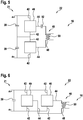
Fig. 2 schematically shows a charging station according to a further embodiment of the invention. -
Fig. 3 schematically shows a charging station according to a further embodiment of the invention. -
Fig. 4 schematically shows a DC-to-AC converter for a charging station according to an embodiment of the invention. -
Fig. 5 schematically shows a further DC-to-AC converter for a charging station according to an embodiment of the invention. -
Fig. 6 schematically shows a further DC-to-AC converter for a charging station according to an embodiment of the invention. -
Fig. 7 schematically shows a converter unit for a charging station according to an embodiment of the invention. -
Fig. 8 schematically shows a further converter unit for a charging station according to an embodiment of the invention. -
Fig. 9 schematically shows a further converter unit for a charging station according to an embodiment of the invention. -
Fig. 10 schematically shows a further converter unit for a charging station according to an embodiment of the invention. -
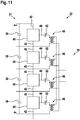
Fig. 11 schematically shows a further DC-to-AC converter for a charging station according to an embodiment of the invention. -
Fig. 12 schematically shows a further DC-to-AC converter for a charging station according to an embodiment of the invention. -
Fig. 13 schematically shows a charging station according to a further embodiment of the invention. -
Fig. 14 schematically shows a charging station according to a further embodiment of the invention. - The reference symbols used in the drawings, and their meanings, are listed in summary form in the list of reference symbols. In principle, identical parts are provided with the same reference symbols in the figures.
-
Fig. 1 shows a chargingstation 10, which comprises acentral part 12 and a plurality of chargingpoles 14, which are interconnected with thecentral part 12 via a high frequencyAC distribution network 16. - The
central part 12 is connected with anelectrical grid 18, which may be three-phase, and theAC distribution network 16, which may be single-phase. Thecentral part 12 converts a medium voltage from thegrid 18 of for example 3.3 kV to 20 kV into a low voltage of for example 230 V to 690 V, which is supplied to thedistribution network 16. The input voltage from theelectrical grid 18 may have a frequency of 50 Hz or 60 Hz. The frequency of the voltage in theAC distribution network 16 may be a high frequency of more than 400 Hz, for example more than 10 kHz. - The
central part 12 may be composed of an AC-to-DC converter 20 and a DC-to-AC converter 22, which are interconnected via aDC link 21. Alternatively, thecentral part 12 may comprise a direct AC-to-AC converter, which may have a single-stage structure, for example by utilizing a matrix-type converter topology. - For the AC-to-
DC converter 20, a medium voltage active or passive rectifier, such as a multi-pulse rectifier with diodes or thyristors may be used. The AC-to-DC converter 20 also may be a multilevel converter and/or a modular multilevel converter. - The DC-to-
AC converter 22 may be a multilevel converter and/or a modular multilevel converter. The DC-to-AC converter 22 may be composed of several converter units as will be described below in more detail. - A
charging pole 14 comprise atransformer 24, which is directly connected with itsprimary coil 26 with theAC distribution network 16. An AC-to-DC converter 30, such as a passive diode rectifier, is connected to asecondary coil 28 of thetransformer 24. It also may be that the AC-to-DC converter is an active rectifier. Acharging pole 14 also may comprise a DC-to-DC converter 32, for example a buck/boost-converter, which is supplied by the AC-to-DC converter 30. To the DC-to-DC converter 32 or to the AC-to-DC converter 30, an electric vehicle may be connected for charging. - In
Fig. 1 , thecomponents central part 12 may be provided in one housing and/or building. - As shown in
Fig. 2 , thecomponents central part 12 also may be distributed into several housings and/or buildings. It also may be possible that at least two DC-to-AC converters 22, such as the ones as described with respect toFig. 1 , are connected to the DC link provided by the AC-to-DC converter 20. - The AC-to-
DC converter 20 and the at least two DC-to-AC converters 22 may be interconnected with aDC distribution network 34. The DC voltage in theDC distribution network 34 may be medium voltage, for example between 3.3 kV and 20 kV. For example, in a rather large chargingstation 10, a single low voltage high frequencyAC distribution network 16 may lead to large conduction losses in theAC distribution network 16. In order to achieve highly efficient distribution, the intermediateDC distribution network 34 may be included. That is, a medium DC voltage, which is available by rectifying a medium voltage AC voltage with the AC-to-DC converter 20, may be used for distribution to reduce long distance conduction losses. The chargingstation 10 and itscentral part 12 may be divided into several sub-charging areas and each sub-charging area may be equipped with a DC-to-AC converter 22, which may convert the medium DC voltage into a low voltage high frequency AC voltage for local distribution. -
Fig. 3 shows a chargingstation 10, for example as inFig. 1 , where the chargingpoles 14 have been replaced withcoils 36 for wireless power transfer. For example,such coils 36 may be provided in a ground below a parking place of anelectric vehicle 38 or in a street. - Also, a high frequency
AC distribution network 16 may be used as a primary side for a wireless power transfer to movingvehicles 38. In this case, by installing the high frequencyAC distribution network 16 along a roadway, even movingelectric vehicles 38 may be charged. - A
secondary coil 37 of theelectric vehicle 38 may couple via a magnetic field with the primary coil 36 (for example via an air gap). Theelectric vehicle 38 itself then may have an AC-to-DC converter 30 and optionally a DC-to-DC converter 32 as described with respect toFig. 1 and/or as described below. - It has to be noted that wireless power transfer coils 36 as described with respect to
Fig. 3 may be combined with the chargingstation 10 ofFig. 1 , where, for example, some of the chargingpoles 14 may be replaced withsuch coils 36. It also may be possible that some or all of the chargingpoles 14 ofFig. 2 connected to one DC-to-AC converter 22 are replaced withcoils 36 for wireless power transfer. - In any of the embodiments described herein, a renewable energy source, such as a photo voltaic power generation station, and/or a battery storage system may be directly connected to the high frequency
AC distribution network 16 and/or theDC distribution network 34. The renewable energy source and/or the battery storage may be connected to the high frequencyAC distribution network 16 via an AC-to-DC converter, analogous to theconverter 22. The renewable energy source and/or the battery storage may be connected to theDC distribution network 34 via a DC-to-DC converter. This DC-to-DC converter also may be of a modular type. - In the embodiments shown in
Fig. 1 to 3 of the chargingstation 10, the power rating of thecentral part 12 may be smaller as the sum of the power ratings of the chargingpoles 14 and/or thecoils 36, when it is assumed that only some of the chargingpoles 14 and/or coils 36 are used for charging. - For example, with respect to
Fig. 1 , the chargingstation 10 may have three chargingpoles 14 and the power rating of an individual charging pole may be 300 kW. Since it is very rare that all the chargingpoles 14 are in operation at the same time, the power rating of thecentral part 12 may be designed lower than the maximum required power. For example, even though the total power rating of all chargingpoles 14 is 900 kW, thecentral part 12 may be designed with a power rating of 600 kW or even of 300 kW. The total installed power rating of power electronics may be reduced with the high frequency AC distribution network supplying more than onecharging pole 14 and/orcoil 36. -
Fig. 4 shows a DC-to-AC converter 22 that may be used in the chargingstations 10 as shown inFig. 1 to 3 . - The DC-to-
AC converter 22 comprises aDC link 21 with acapacitor 39, aconverter unit 40 connected in parallel with itsinputs 42 to theDC link 21 and atransformer 46, which is connected with itsprimary coil 48 to anoutput 44 of theconverter unit 40. Thesecondary coil 50 of thetransformer 46 is connected to the high frequencyAC distribution network 16. ADC blocking capacitor 52 may be interconnected between theoutput 44 and theprimary coil 48. - As shown in
Fig. 5 , in the case of higher voltages, two ormore converter units 40 may be connected in series with theirinput 42. Every one of theseconverter units 40 may be connected in parallel to acapacitor 39 of asplit DC link 21, which is composed of series-connectedcapacitors 39. In the case ofFig. 5 , theoutputs 44 of twoconverter units 40 may be connected via theprimary coil 48 of thetransformer 46 with each other. - As shown in
Fig. 6 , in the case of higher currents, two ormore converter units 40 may be connected in parallel with theirinputs 42 and in parallel to theDC link 21. As inFig. 5 , theoutputs 44 of twoconverter units 40 may be connected via theprimary coil 48 of thetransformer 46 with each other. -
Fig. 7 to 8 show possible topologies for theconverter units 40 as shown inFig. 4 to 6 and below. -
Fig. 7 to 9 show converter units 40, which comprise 4 series-connected semiconductor switches 54, which are interconnected between theinputs 42. At the middle point, theswitches 54 provide theoutput 44. Everyconverter unit 40 may comprise and/or may be interconnected with aDC link 56, which may comprise one or more series-connectedcapacitors 58. -
Fig. 7 is a neutral point clampedconverter unit 40, in which two intermediate middle points between two upper und twolower switches 54 are connected viadiodes 60 with a middle point of asplit DC link 56. -
Fig. 8 is a T-type converter unit 40, where the middle point between theswitches 54 providing theoutput 44 is interconnected via two anti-series-connectedswitches 62 with the middle point of thesplit DC link 56. -
Fig. 9 is a flying capacitortype converter unit 40, where two intermediate middle points between two upper und twolower switches 54 are connected via acapacitor 64 with each other. -
Fig. 10 shows a modularmulti-level converter unit 40, which comprises a plurality of series-connectedconverter modules 66, which are interconnected between theinputs 42. Theoutput 44 is provided at a middle point between theconverter modules 66. Everyconverter module 66 may comprise aconverter bridge 68 composed of twoswitches 70 and acapacitor 72 connected in parallel to theconverter bridge 68. -
Fig. 11 andFig. 12 show two further examples of a DC-to-AC converter 22. A plurality of converter units 40 (here 4) are connected in series with theirinputs 42. Every one of theseconverter units 40 is connected in parallel to acapacitor 39 of asplit DC link 21, which is composed of series-connectedcapacitors 39. - In
Fig. 11 , everyconverter unit 22 is associated with onetransformer 46. Theoutput 44 of everyconverter unit 22 is connected via the primary coil of thetransformer 46 with one of itsinputs 42. Alltransformers 46 are connected in parallel with their secondary coils. - In
Fig. 12 , twoconverter units 22 are associated with onetransformer 46. Theoutput 44 of afirst converter unit 22 is connected via the primary coil of therespective transformer 46 with theoutput 44 of asecond converter unit 22. Again, thetransformers 46 are connected in parallel with their secondary coils. -
Fig. 13 andFig. 14 show further examples of charging stations, where aresonant tank 74 is provided in the high frequency section. Resonant operation may be used for the high frequencyAC distribution network 16. - The
resonant tank 74 may comprise aresonant capacitor 76 and aresonant inductor 78 and/or may be used to make the current waveform in thedistribution network 16 more of sinusoidal shape. With a resonant operation, a soft switching for theconverter units 40 of the DC-to-AC converter 22 may be achieved. - As shown in
Fig. 13 , one way to implement the resonant operation is inserting theresonant tank 74 directly in thedistribution network 16. Theresonant tank 74 may be connected between the one ormore transformers 46 of thecentral part 12 and thetransformers 24 of the charging poles 14 (and/or thecoils 36 for wireless power transfer). - As shown in
Fig. 14 , one or moreresonant tanks 74 may be connected between theoutput 44 of aconverter unit 40 and thetransformer 46. In this case, aresonant tank 74 may be provided for everytransformer 46. In general, theDC blocking capacitor 52 and aleakage inductance 78 of thetransformer 46 may be used for theresonant tank 74. -
Fig. 14 furthermore shows an exemplary overall circuit diagram of a chargingstation 10. For every phase of the medium voltage from thegrid 18, the AC-to-DC converter 20 of thecentral part 12 comprises a modular multi-level converter as shown inFig. 10 , which is composed ofconverter modules 66 as shown inFig. 10 . These modular multi-level converters are connected in parallel to theDC link 21. - In general, the AC-to-
DC converter 20 of thecentral part 12 may be of any type of rectifier stage. Like the DC-to-AC converter 22, a modular converter and/or the converter types as shown inFig. 7 to 10 may be used. - In summary, the high frequency
AC distribution network 16 in particular in combination with a modular DC-to-AC converter 22 of thecentral part 12 of the chargingstation 10 may result in a small foot print and high power density for thehigh frequency transformers grid 18 is possible due to the modularity of the DC-to-AC converter 22. Furthermore, the power rating of thecentral part 12 may be reduced and the solution is compatible with the interconnection of renewable energy source and an energy storage for grid support and micro-grid functionalities. - While the invention has been illustrated and described in detail in the drawings and foregoing description, such illustration and description are to be considered illustrative or exemplary and not restrictive; the invention is not limited to the disclosed embodiments. Other variations to the disclosed embodiments can be understood and effected by those skilled in the art and practising the claimed invention, from a study of the drawings, the disclosure, and the appended claims. In the claims, the word "comprising" does not exclude other elements or steps, and the indefinite article "a" or "an" does not exclude a plurality. A single processor or controller or other unit may fulfil the functions of several items recited in the claims. The mere fact that certain measures are recited in mutually different dependent claims does not indicate that a combination of these measures cannot be used to advantage. Any reference signs in the claims should not be construed as limiting the scope.
-
- 10
- charging station
- 12
- central part
- 14
- charging pole
- 16
- high frequency AC distribution network
- 18
- electrical grid
- 20
- AC-to-DC converter
- 21
- DC link
- 22
- DC-to-AC converter
- 24
- transformer
- 26
- primary coil
- 28
- secondary coil
- 30
- AC-to-DC converter
- 32
- DC-to-DC converter
- 34
- DC distribution network
- 36
- coil for wireless power transfer
- 37
- secondary coil of electric vehicle
- 38
- electric vehicle
- 39
- DC link capacitor
- 40
- converter unit
- 42
- input
- 44
- output
- 46
- transformer
- 48
- primary coil
- 50
- secondary coil
- 52
- DC blocking capacitor
- 54
- semiconductor switch
- 56
- DC link
- 58
- capacitor
- 60
- diode
- 62
- semiconductor switch
- 64
- capacitor
- 66
- converter module
- 68
- converter bridge
- 70
- semiconductor switch
- 72
- capacitor
- 74
- resonant tank
- 76
- capacitor
- 78
- inductor
Claims (15)
- A charging station (10) for electric vehicles (38), the charging station (10) comprising:a central part (12) for converting a grid AC voltage from an electrical grid (18) into a high frequency AC voltage;a distribution network (16) for distributing the high frequency AC voltage;a plurality of coils (26, 36) directly connected to the distribution network (16), wherein each coil (26, 36) is adapted for transferring energy to an electrical vehicle (38).
- The charging station (10) of claim 1,
wherein the central part (12) comprises at least one transformer (46) at its output side, which is connected to the distribution network (16); and/or
wherein the central part (12) comprises at least two transformers (46) having secondary coils (50) connected in parallel and/or in series to the distribution network (16). - The charging station (10) of claim 1 or 2,
wherein the central part (12) comprises a grid side AC-to-DC converter (20) for receiving the grid voltage and at least one network side DC-to-AC converter (22), which are interconnected via a DC link (21). - The charging station (10) of claim 3,
wherein the central part (12) comprises at least two DC-to-AC converters (22), which are connected to the DC link (21) via a DC distribution network (34). - The charging station (10) of one of claims 3 or 4,
wherein the DC-to-AC converter (22) is composed of at least one converter unit (40), which is one of neutral point clamped type, T type, flying cap type, modular multi-level converter type. - The charging station (10) of one of claims 3 to 5,
wherein the DC-to-AC converter (22) is composed of at least two converter units (40), which are connected in series with their inputs (42); and/or
wherein the DC-to-AC converter (22) is composed of at least two converter units (40), which are connected in parallel with their inputs (42). - The charging station (10) of one of claims 4 to 6,
wherein the DC-to-AC converter (22) comprises two converter units (40), which are connected via a transformer (46) of the central part (12) with their outputs (44). - The charging station (10) of one of the previous claims,
wherein a resonant tank (74) comprising a capacitor (76) and an inductor (78) is connected in the distribution network (16). - The charging station (10) of claim 8,
wherein the resonant tank (74) is connected between a transformer (46) of the central part (12) and the coils (26, 36). - The charging station (10) of one of the previous claims,
wherein a resonant tank (74) comprising a capacitor (76) and an inductor (78) is connected between a converter unit (40) of the central part (12) and a transformer (46) of the central part (12). - The charging station (10) of one of the previous claims,
wherein the grid voltage is a medium voltage of more than 3 kV; and/or
wherein the high frequency AC voltage is a low voltage of less than 3 kV. - The charging station (10) of one of the previous claims,
wherein the frequency of the grid AC voltage is less than 100 Hz; and/or
wherein the frequency of the high frequency AC voltage is more than 400 Hz. - The charging station (10) of one of the previous claims,
wherein at least some of the coils (26) are part of a transformer (24) integrated into a charging pole (14). - The charging station (10) of claim 13,
wherein the charging pole (14) comprises an AC-to-DC converter (30) for receiving a voltage from the transformer (24);
wherein the AC-to-DC converter (30) of the charging pole (14) supplies a DC-to-DC converter (32) for generating a charging voltage. - The charging station (10) of one of the previous claims,
wherein at least some of the coils are coils (36) for wireless energy transfer via an air gap.
Priority Applications (5)
| Application Number | Priority Date | Filing Date | Title |
|---|---|---|---|
| ES19150044T ES2926686T3 (en) | 2019-01-02 | 2019-01-02 | Charging station with high frequency distribution network |
| EP19150044.6A EP3678278B1 (en) | 2019-01-02 | 2019-01-02 | Charging station with high frequency distribution network |
| CN201980087719.4A CN113228461A (en) | 2019-01-02 | 2019-12-10 | Charging station adopting high-frequency power distribution network |
| PCT/EP2019/084452 WO2020141047A1 (en) | 2019-01-02 | 2019-12-10 | Charging station with high frequency distribution network |
| US17/366,488 US12255461B2 (en) | 2019-01-02 | 2021-07-02 | Charging station with high frequency distribution network |
Applications Claiming Priority (1)
| Application Number | Priority Date | Filing Date | Title |
|---|---|---|---|
| EP19150044.6A EP3678278B1 (en) | 2019-01-02 | 2019-01-02 | Charging station with high frequency distribution network |
Publications (2)
| Publication Number | Publication Date |
|---|---|
| EP3678278A1 true EP3678278A1 (en) | 2020-07-08 |
| EP3678278B1 EP3678278B1 (en) | 2022-06-08 |
Family
ID=64949150
Family Applications (1)
| Application Number | Title | Priority Date | Filing Date |
|---|---|---|---|
| EP19150044.6A Active EP3678278B1 (en) | 2019-01-02 | 2019-01-02 | Charging station with high frequency distribution network |
Country Status (5)
| Country | Link |
|---|---|
| US (1) | US12255461B2 (en) |
| EP (1) | EP3678278B1 (en) |
| CN (1) | CN113228461A (en) |
| ES (1) | ES2926686T3 (en) |
| WO (1) | WO2020141047A1 (en) |
Cited By (3)
| Publication number | Priority date | Publication date | Assignee | Title |
|---|---|---|---|---|
| CN112455269A (en) * | 2020-11-27 | 2021-03-09 | 国网智慧能源交通技术创新中心(苏州)有限公司 | Charging vehicle dispatching system and method combining charging and battery replacement |
| CN114514680A (en) * | 2020-09-14 | 2022-05-17 | 华为技术有限公司 | DC/DC power converter, method for controlling switching of a DC/DC power converter, DC/DC power converter arrangement, and system |
| US11351879B2 (en) * | 2017-10-06 | 2022-06-07 | Proterra Operating Company, Inc. | Depot charging of an electric vehicle fleet |
Families Citing this family (3)
| Publication number | Priority date | Publication date | Assignee | Title |
|---|---|---|---|---|
| US20240106335A1 (en) * | 2020-11-04 | 2024-03-28 | Auckland Uniservices Limited | A converter |
| JP2024068843A (en) * | 2022-11-09 | 2024-05-21 | 株式会社日立製作所 | Power conversion device and control method for power conversion device |
| US20240424918A1 (en) * | 2023-06-21 | 2024-12-26 | Ford Global Technologies, Llc | Traction inverter integration with three-phase resonant dc/dc converter |
Citations (4)
| Publication number | Priority date | Publication date | Assignee | Title |
|---|---|---|---|---|
| EP2514627A1 (en) * | 2011-04-20 | 2012-10-24 | Siemens Aktiengesellschaft | Converter for charging batteries in an electric vehicle and for feeding back to supply network |
| US9030843B1 (en) * | 2010-02-12 | 2015-05-12 | Edward Herbert | High frequency square-wave power distribution system |
| US20160031330A1 (en) * | 2014-07-31 | 2016-02-04 | Toyota Motor Engineering & Manufacturing North America, Inc. | Modular wireless electrical system |
| US20170158064A1 (en) * | 2014-03-04 | 2017-06-08 | Technova Inc. | System for wirelessly supplying power during moving |
Family Cites Families (10)
| Publication number | Priority date | Publication date | Assignee | Title |
|---|---|---|---|---|
| US9515494B2 (en) * | 2008-09-27 | 2016-12-06 | Witricity Corporation | Wireless power system including impedance matching network |
| US9561730B2 (en) * | 2010-04-08 | 2017-02-07 | Qualcomm Incorporated | Wireless power transmission in electric vehicles |
| US9859755B2 (en) * | 2012-07-16 | 2018-01-02 | Qualcomm Incorporated | Device alignment and identification in inductive power transfer systems |
| CN203368042U (en) | 2013-07-25 | 2013-12-25 | 南方电网科学研究院有限责任公司 | Energy storage system based on IEGT |
| CN103595109B (en) * | 2013-12-03 | 2016-03-30 | 东南大学 | A kind of electric automobile mobile charging method and apparatus |
| CN106541845B (en) * | 2016-11-25 | 2018-09-11 | 上海工程技术大学 | A kind of wireless electric automobile charging system actual and control method |
| US10919401B2 (en) * | 2017-01-12 | 2021-02-16 | Ford Global Technologies, Llc | Integrated wireless power transfer system |
| CN207579603U (en) * | 2017-09-13 | 2018-07-06 | 沈阳工程学院 | Automatically correct the wireless electric vehicle charging device of coil position |
| US10557901B2 (en) * | 2018-02-21 | 2020-02-11 | General Electric Company | Systems and methods for providing gradient power for an MRI system |
| US11002874B2 (en) * | 2018-12-21 | 2021-05-11 | Witricity Corporation | Foreign object detection circuit using mutual impedance sensing |
-
2019
- 2019-01-02 EP EP19150044.6A patent/EP3678278B1/en active Active
- 2019-01-02 ES ES19150044T patent/ES2926686T3/en active Active
- 2019-12-10 WO PCT/EP2019/084452 patent/WO2020141047A1/en not_active Ceased
- 2019-12-10 CN CN201980087719.4A patent/CN113228461A/en active Pending
-
2021
- 2021-07-02 US US17/366,488 patent/US12255461B2/en active Active
Patent Citations (4)
| Publication number | Priority date | Publication date | Assignee | Title |
|---|---|---|---|---|
| US9030843B1 (en) * | 2010-02-12 | 2015-05-12 | Edward Herbert | High frequency square-wave power distribution system |
| EP2514627A1 (en) * | 2011-04-20 | 2012-10-24 | Siemens Aktiengesellschaft | Converter for charging batteries in an electric vehicle and for feeding back to supply network |
| US20170158064A1 (en) * | 2014-03-04 | 2017-06-08 | Technova Inc. | System for wirelessly supplying power during moving |
| US20160031330A1 (en) * | 2014-07-31 | 2016-02-04 | Toyota Motor Engineering & Manufacturing North America, Inc. | Modular wireless electrical system |
Cited By (4)
| Publication number | Priority date | Publication date | Assignee | Title |
|---|---|---|---|---|
| US11351879B2 (en) * | 2017-10-06 | 2022-06-07 | Proterra Operating Company, Inc. | Depot charging of an electric vehicle fleet |
| US20220348095A1 (en) * | 2017-10-06 | 2022-11-03 | Proterra Operating Company, Inc. | Depot charging of an electric vehicle fleet |
| CN114514680A (en) * | 2020-09-14 | 2022-05-17 | 华为技术有限公司 | DC/DC power converter, method for controlling switching of a DC/DC power converter, DC/DC power converter arrangement, and system |
| CN112455269A (en) * | 2020-11-27 | 2021-03-09 | 国网智慧能源交通技术创新中心(苏州)有限公司 | Charging vehicle dispatching system and method combining charging and battery replacement |
Also Published As
| Publication number | Publication date |
|---|---|
| ES2926686T3 (en) | 2022-10-27 |
| CN113228461A (en) | 2021-08-06 |
| US20210336440A1 (en) | 2021-10-28 |
| EP3678278B1 (en) | 2022-06-08 |
| US12255461B2 (en) | 2025-03-18 |
| WO2020141047A1 (en) | 2020-07-09 |
Similar Documents
| Publication | Publication Date | Title |
|---|---|---|
| US12255461B2 (en) | Charging station with high frequency distribution network | |
| Alhurayyis et al. | Isolated and nonisolated DC-to-DC converters for medium-voltage DC networks: A review | |
| Chub et al. | Bidirectional DC–DC converter for modular residential battery energy storage systems | |
| US12083913B2 (en) | Systems, apparatus and methods for electric vehicle charging via a power conversion system | |
| Fan et al. | High-frequency transformer isolated bidirectional DC–DC converter modules with high efficiency over wide load range for 20 kVA solid-state transformer | |
| Zhao et al. | Advanced symmetrical voltage quadrupler rectifiers for high step-up and high output-voltage converters | |
| Han et al. | A new active clamping zero-voltage switching PWM current-fed half-bridge converter | |
| US20110273917A1 (en) | Intelligent photovoltaic interface and system | |
| Kolar et al. | Solid-state-transformers: Key components of future traction and smart grid systems | |
| EP2815913A1 (en) | Recharging system for electric vehicles | |
| EP2636122B1 (en) | System and method for bidirectional dc-ac power conversion | |
| EP3776797B1 (en) | Charging station for electric vehicles | |
| US9748848B2 (en) | Modular multilevel DC/DC converter for HVDC applications | |
| US9362848B2 (en) | Hybrid AC/DC converter for HVDC applications | |
| EP2719062B1 (en) | High voltage dc/dc converter with cascaded resonant tanks | |
| EP3985821A1 (en) | Power grid | |
| US20230352934A1 (en) | Power grid | |
| US20150222140A1 (en) | Switchable energy storage device and method for operating a switchable energy storage device | |
| Lee et al. | Nonisolated ZVT two-inductor boost converter with a single resonant inductor for high step-up applications | |
| Jaga et al. | Bi-directional dc/dc converters used in interfacing esss for ress and evs: a review | |
| Taufik et al. | Multiple-Input Single-Output converter for renewable energy sources | |
| Schumacher et al. | Standalone integrated power electronics system: Applications for off-grid rural locations | |
| EP4489285A1 (en) | Converter and method of transferring power from a medium voltage side to a low voltage side in a converter | |
| KR20240021120A (en) | Method and circuit for an integrated dc-dc converter in an ac battery | |
| Vu et al. | Design and implementation of a multi-output inductive charger for electric vehicles |
Legal Events
| Date | Code | Title | Description |
|---|---|---|---|
| PUAI | Public reference made under article 153(3) epc to a published international application that has entered the european phase |
Free format text: ORIGINAL CODE: 0009012 |
|
| STAA | Information on the status of an ep patent application or granted ep patent |
Free format text: STATUS: THE APPLICATION HAS BEEN PUBLISHED |
|
| AK | Designated contracting states |
Kind code of ref document: A1 Designated state(s): AL AT BE BG CH CY CZ DE DK EE ES FI FR GB GR HR HU IE IS IT LI LT LU LV MC MK MT NL NO PL PT RO RS SE SI SK SM TR |
|
| AX | Request for extension of the european patent |
Extension state: BA ME |
|
| STAA | Information on the status of an ep patent application or granted ep patent |
Free format text: STATUS: REQUEST FOR EXAMINATION WAS MADE |
|
| 17P | Request for examination filed |
Effective date: 20201209 |
|
| RBV | Designated contracting states (corrected) |
Designated state(s): AL AT BE BG CH CY CZ DE DK EE ES FI FR GB GR HR HU IE IS IT LI LT LU LV MC MK MT NL NO PL PT RO RS SE SI SK SM TR |
|
| GRAP | Despatch of communication of intention to grant a patent |
Free format text: ORIGINAL CODE: EPIDOSNIGR1 |
|
| STAA | Information on the status of an ep patent application or granted ep patent |
Free format text: STATUS: GRANT OF PATENT IS INTENDED |
|
| INTG | Intention to grant announced |
Effective date: 20220110 |
|
| GRAS | Grant fee paid |
Free format text: ORIGINAL CODE: EPIDOSNIGR3 |
|
| GRAA | (expected) grant |
Free format text: ORIGINAL CODE: 0009210 |
|
| STAA | Information on the status of an ep patent application or granted ep patent |
Free format text: STATUS: THE PATENT HAS BEEN GRANTED |
|
| RAP3 | Party data changed (applicant data changed or rights of an application transferred) |
Owner name: ABB SCHWEIZ AG |
|
| AK | Designated contracting states |
Kind code of ref document: B1 Designated state(s): AL AT BE BG CH CY CZ DE DK EE ES FI FR GB GR HR HU IE IS IT LI LT LU LV MC MK MT NL NO PL PT RO RS SE SI SK SM TR |
|
| REG | Reference to a national code |
Ref country code: AT Ref legal event code: REF Ref document number: 1497586 Country of ref document: AT Kind code of ref document: T Effective date: 20220615 Ref country code: CH Ref legal event code: EP |
|
| REG | Reference to a national code |
Ref country code: DE Ref legal event code: R096 Ref document number: 602019015532 Country of ref document: DE |
|
| REG | Reference to a national code |
Ref country code: IE Ref legal event code: FG4D |
|
| REG | Reference to a national code |
Ref country code: NL Ref legal event code: FP |
|
| REG | Reference to a national code |
Ref country code: LT Ref legal event code: MG9D |
|
| REG | Reference to a national code |
Ref country code: SE Ref legal event code: TRGR |
|
| REG | Reference to a national code |
Ref country code: ES Ref legal event code: FG2A Ref document number: 2926686 Country of ref document: ES Kind code of ref document: T3 Effective date: 20221027 |
|
| PG25 | Lapsed in a contracting state [announced via postgrant information from national office to epo] |
Ref country code: NO Free format text: LAPSE BECAUSE OF FAILURE TO SUBMIT A TRANSLATION OF THE DESCRIPTION OR TO PAY THE FEE WITHIN THE PRESCRIBED TIME-LIMIT Effective date: 20220908 Ref country code: LT Free format text: LAPSE BECAUSE OF FAILURE TO SUBMIT A TRANSLATION OF THE DESCRIPTION OR TO PAY THE FEE WITHIN THE PRESCRIBED TIME-LIMIT Effective date: 20220608 Ref country code: HR Free format text: LAPSE BECAUSE OF FAILURE TO SUBMIT A TRANSLATION OF THE DESCRIPTION OR TO PAY THE FEE WITHIN THE PRESCRIBED TIME-LIMIT Effective date: 20220608 Ref country code: GR Free format text: LAPSE BECAUSE OF FAILURE TO SUBMIT A TRANSLATION OF THE DESCRIPTION OR TO PAY THE FEE WITHIN THE PRESCRIBED TIME-LIMIT Effective date: 20220909 Ref country code: FI Free format text: LAPSE BECAUSE OF FAILURE TO SUBMIT A TRANSLATION OF THE DESCRIPTION OR TO PAY THE FEE WITHIN THE PRESCRIBED TIME-LIMIT Effective date: 20220608 Ref country code: BG Free format text: LAPSE BECAUSE OF FAILURE TO SUBMIT A TRANSLATION OF THE DESCRIPTION OR TO PAY THE FEE WITHIN THE PRESCRIBED TIME-LIMIT Effective date: 20220908 |
|
| RAP2 | Party data changed (patent owner data changed or rights of a patent transferred) |
Owner name: ABB-E-MOBILITY B.V. |
|
| REG | Reference to a national code |
Ref country code: AT Ref legal event code: MK05 Ref document number: 1497586 Country of ref document: AT Kind code of ref document: T Effective date: 20220608 |
|
| PG25 | Lapsed in a contracting state [announced via postgrant information from national office to epo] |
Ref country code: RS Free format text: LAPSE BECAUSE OF FAILURE TO SUBMIT A TRANSLATION OF THE DESCRIPTION OR TO PAY THE FEE WITHIN THE PRESCRIBED TIME-LIMIT Effective date: 20220608 Ref country code: LV Free format text: LAPSE BECAUSE OF FAILURE TO SUBMIT A TRANSLATION OF THE DESCRIPTION OR TO PAY THE FEE WITHIN THE PRESCRIBED TIME-LIMIT Effective date: 20220608 |
|
| PG25 | Lapsed in a contracting state [announced via postgrant information from national office to epo] |
Ref country code: SM Free format text: LAPSE BECAUSE OF FAILURE TO SUBMIT A TRANSLATION OF THE DESCRIPTION OR TO PAY THE FEE WITHIN THE PRESCRIBED TIME-LIMIT Effective date: 20220608 Ref country code: SK Free format text: LAPSE BECAUSE OF FAILURE TO SUBMIT A TRANSLATION OF THE DESCRIPTION OR TO PAY THE FEE WITHIN THE PRESCRIBED TIME-LIMIT Effective date: 20220608 Ref country code: RO Free format text: LAPSE BECAUSE OF FAILURE TO SUBMIT A TRANSLATION OF THE DESCRIPTION OR TO PAY THE FEE WITHIN THE PRESCRIBED TIME-LIMIT Effective date: 20220608 Ref country code: PT Free format text: LAPSE BECAUSE OF FAILURE TO SUBMIT A TRANSLATION OF THE DESCRIPTION OR TO PAY THE FEE WITHIN THE PRESCRIBED TIME-LIMIT Effective date: 20221010 Ref country code: EE Free format text: LAPSE BECAUSE OF FAILURE TO SUBMIT A TRANSLATION OF THE DESCRIPTION OR TO PAY THE FEE WITHIN THE PRESCRIBED TIME-LIMIT Effective date: 20220608 Ref country code: CZ Free format text: LAPSE BECAUSE OF FAILURE TO SUBMIT A TRANSLATION OF THE DESCRIPTION OR TO PAY THE FEE WITHIN THE PRESCRIBED TIME-LIMIT Effective date: 20220608 Ref country code: AT Free format text: LAPSE BECAUSE OF FAILURE TO SUBMIT A TRANSLATION OF THE DESCRIPTION OR TO PAY THE FEE WITHIN THE PRESCRIBED TIME-LIMIT Effective date: 20220608 |
|
| PG25 | Lapsed in a contracting state [announced via postgrant information from national office to epo] |
Ref country code: PL Free format text: LAPSE BECAUSE OF FAILURE TO SUBMIT A TRANSLATION OF THE DESCRIPTION OR TO PAY THE FEE WITHIN THE PRESCRIBED TIME-LIMIT Effective date: 20220608 Ref country code: IS Free format text: LAPSE BECAUSE OF FAILURE TO SUBMIT A TRANSLATION OF THE DESCRIPTION OR TO PAY THE FEE WITHIN THE PRESCRIBED TIME-LIMIT Effective date: 20221008 |
|
| REG | Reference to a national code |
Ref country code: DE Ref legal event code: R097 Ref document number: 602019015532 Country of ref document: DE |
|
| PG25 | Lapsed in a contracting state [announced via postgrant information from national office to epo] |
Ref country code: AL Free format text: LAPSE BECAUSE OF FAILURE TO SUBMIT A TRANSLATION OF THE DESCRIPTION OR TO PAY THE FEE WITHIN THE PRESCRIBED TIME-LIMIT Effective date: 20220608 |
|
| PLBE | No opposition filed within time limit |
Free format text: ORIGINAL CODE: 0009261 |
|
| STAA | Information on the status of an ep patent application or granted ep patent |
Free format text: STATUS: NO OPPOSITION FILED WITHIN TIME LIMIT |
|
| PG25 | Lapsed in a contracting state [announced via postgrant information from national office to epo] |
Ref country code: DK Free format text: LAPSE BECAUSE OF FAILURE TO SUBMIT A TRANSLATION OF THE DESCRIPTION OR TO PAY THE FEE WITHIN THE PRESCRIBED TIME-LIMIT Effective date: 20220608 |
|
| 26N | No opposition filed |
Effective date: 20230310 |
|
| PG25 | Lapsed in a contracting state [announced via postgrant information from national office to epo] |
Ref country code: SI Free format text: LAPSE BECAUSE OF FAILURE TO SUBMIT A TRANSLATION OF THE DESCRIPTION OR TO PAY THE FEE WITHIN THE PRESCRIBED TIME-LIMIT Effective date: 20220608 |
|
| PG25 | Lapsed in a contracting state [announced via postgrant information from national office to epo] |
Ref country code: LU Free format text: LAPSE BECAUSE OF NON-PAYMENT OF DUE FEES Effective date: 20230102 |
|
| REG | Reference to a national code |
Ref country code: BE Ref legal event code: MM Effective date: 20230131 |
|
| PG25 | Lapsed in a contracting state [announced via postgrant information from national office to epo] |
Ref country code: BE Free format text: LAPSE BECAUSE OF NON-PAYMENT OF DUE FEES Effective date: 20230131 |
|
| PG25 | Lapsed in a contracting state [announced via postgrant information from national office to epo] |
Ref country code: IE Free format text: LAPSE BECAUSE OF NON-PAYMENT OF DUE FEES Effective date: 20230102 |
|
| PG25 | Lapsed in a contracting state [announced via postgrant information from national office to epo] |
Ref country code: MC Free format text: LAPSE BECAUSE OF FAILURE TO SUBMIT A TRANSLATION OF THE DESCRIPTION OR TO PAY THE FEE WITHIN THE PRESCRIBED TIME-LIMIT Effective date: 20220608 |
|
| PG25 | Lapsed in a contracting state [announced via postgrant information from national office to epo] |
Ref country code: MC Free format text: LAPSE BECAUSE OF FAILURE TO SUBMIT A TRANSLATION OF THE DESCRIPTION OR TO PAY THE FEE WITHIN THE PRESCRIBED TIME-LIMIT Effective date: 20220608 |
|
| REG | Reference to a national code |
Ref country code: NL Ref legal event code: PD Owner name: ABB E-MOBILITY B.V.; NL Free format text: DETAILS ASSIGNMENT: CHANGE OF OWNER(S), ASSIGNMENT; FORMER OWNER NAME: ABB SCHWEIZ AG Effective date: 20240807 |
|
| REG | Reference to a national code |
Ref country code: GB Ref legal event code: 732E Free format text: REGISTERED BETWEEN 20240801 AND 20240807 |
|
| REG | Reference to a national code |
Ref country code: DE Ref legal event code: R081 Ref document number: 602019015532 Country of ref document: DE Owner name: ABB E-MOBILITY B.V., NL Free format text: FORMER OWNER: ABB SCHWEIZ AG, BADEN, CH |
|
| PG25 | Lapsed in a contracting state [announced via postgrant information from national office to epo] |
Ref country code: BG Free format text: LAPSE BECAUSE OF FAILURE TO SUBMIT A TRANSLATION OF THE DESCRIPTION OR TO PAY THE FEE WITHIN THE PRESCRIBED TIME-LIMIT Effective date: 20220608 |
|
| PG25 | Lapsed in a contracting state [announced via postgrant information from national office to epo] |
Ref country code: BG Free format text: LAPSE BECAUSE OF FAILURE TO SUBMIT A TRANSLATION OF THE DESCRIPTION OR TO PAY THE FEE WITHIN THE PRESCRIBED TIME-LIMIT Effective date: 20220608 |
|
| PG25 | Lapsed in a contracting state [announced via postgrant information from national office to epo] |
Ref country code: CY Free format text: LAPSE BECAUSE OF FAILURE TO SUBMIT A TRANSLATION OF THE DESCRIPTION OR TO PAY THE FEE WITHIN THE PRESCRIBED TIME-LIMIT; INVALID AB INITIO Effective date: 20190102 |
|
| PG25 | Lapsed in a contracting state [announced via postgrant information from national office to epo] |
Ref country code: HU Free format text: LAPSE BECAUSE OF FAILURE TO SUBMIT A TRANSLATION OF THE DESCRIPTION OR TO PAY THE FEE WITHIN THE PRESCRIBED TIME-LIMIT; INVALID AB INITIO Effective date: 20190102 |
|
| PG25 | Lapsed in a contracting state [announced via postgrant information from national office to epo] |
Ref country code: TR Free format text: LAPSE BECAUSE OF FAILURE TO SUBMIT A TRANSLATION OF THE DESCRIPTION OR TO PAY THE FEE WITHIN THE PRESCRIBED TIME-LIMIT Effective date: 20220608 |
|
| REG | Reference to a national code |
Ref country code: CH Ref legal event code: U11 Free format text: ST27 STATUS EVENT CODE: U-0-0-U10-U11 (AS PROVIDED BY THE NATIONAL OFFICE) Effective date: 20260201 |
|
| PGFP | Annual fee paid to national office [announced via postgrant information from national office to epo] |
Ref country code: NL Payment date: 20260121 Year of fee payment: 8 |
|
| PGFP | Annual fee paid to national office [announced via postgrant information from national office to epo] |
Ref country code: SE Payment date: 20260121 Year of fee payment: 8 |
|
| PGFP | Annual fee paid to national office [announced via postgrant information from national office to epo] |
Ref country code: GB Payment date: 20260123 Year of fee payment: 8 |
|
| PGFP | Annual fee paid to national office [announced via postgrant information from national office to epo] |
Ref country code: ES Payment date: 20260227 Year of fee payment: 8 |
|
| PGFP | Annual fee paid to national office [announced via postgrant information from national office to epo] |
Ref country code: DE Payment date: 20260121 Year of fee payment: 8 |
|
| PGFP | Annual fee paid to national office [announced via postgrant information from national office to epo] |
Ref country code: IT Payment date: 20260126 Year of fee payment: 8 |
|
| PGFP | Annual fee paid to national office [announced via postgrant information from national office to epo] |
Ref country code: FR Payment date: 20260123 Year of fee payment: 8 |
|
| PGFP | Annual fee paid to national office [announced via postgrant information from national office to epo] |
Ref country code: CH Payment date: 20260201 Year of fee payment: 8 |