EP3678158A1 - Magnetic actuator and electromagnetic relay - Google Patents
Magnetic actuator and electromagnetic relay Download PDFInfo
- Publication number
- EP3678158A1 EP3678158A1 EP19398001.8A EP19398001A EP3678158A1 EP 3678158 A1 EP3678158 A1 EP 3678158A1 EP 19398001 A EP19398001 A EP 19398001A EP 3678158 A1 EP3678158 A1 EP 3678158A1
- Authority
- EP
- European Patent Office
- Prior art keywords
- armature
- magnetic
- electromagnet
- movable contact
- contact element
- Prior art date
- Legal status (The legal status is an assumption and is not a legal conclusion. Google has not performed a legal analysis and makes no representation as to the accuracy of the status listed.)
- Granted
Links
- 230000007935 neutral effect Effects 0.000 claims abstract description 54
- 230000004907 flux Effects 0.000 claims abstract description 18
- 238000000926 separation method Methods 0.000 claims description 10
- 230000010287 polarization Effects 0.000 claims description 7
- 230000004044 response Effects 0.000 abstract description 4
- 230000001939 inductive effect Effects 0.000 description 8
- 230000008878 coupling Effects 0.000 description 6
- 238000010168 coupling process Methods 0.000 description 6
- 238000005859 coupling reaction Methods 0.000 description 6
- 230000000284 resting effect Effects 0.000 description 6
- 230000002441 reversible effect Effects 0.000 description 6
- 238000010586 diagram Methods 0.000 description 4
- 230000002829 reductive effect Effects 0.000 description 3
- 230000008901 benefit Effects 0.000 description 2
- 230000000670 limiting effect Effects 0.000 description 2
- 239000000463 material Substances 0.000 description 2
- 230000013011 mating Effects 0.000 description 2
- 238000004088 simulation Methods 0.000 description 2
- 230000009471 action Effects 0.000 description 1
- 230000003213 activating effect Effects 0.000 description 1
- 230000004913 activation Effects 0.000 description 1
- 230000000903 blocking effect Effects 0.000 description 1
- 230000008859 change Effects 0.000 description 1
- 239000012141 concentrate Substances 0.000 description 1
- 230000007423 decrease Effects 0.000 description 1
- 230000003247 decreasing effect Effects 0.000 description 1
- 230000001419 dependent effect Effects 0.000 description 1
- 238000007599 discharging Methods 0.000 description 1
- 238000006073 displacement reaction Methods 0.000 description 1
- 230000005284 excitation Effects 0.000 description 1
- 238000003780 insertion Methods 0.000 description 1
- 230000037431 insertion Effects 0.000 description 1
- 239000000696 magnetic material Substances 0.000 description 1
- 230000035945 sensitivity Effects 0.000 description 1
- 238000003466 welding Methods 0.000 description 1
Images


Classifications
-
- H—ELECTRICITY
- H01—ELECTRIC ELEMENTS
- H01H—ELECTRIC SWITCHES; RELAYS; SELECTORS; EMERGENCY PROTECTIVE DEVICES
- H01H51/00—Electromagnetic relays
- H01H51/22—Polarised relays
- H01H51/2236—Polarised relays comprising pivotable armature, pivoting at extremity or bending point of armature
-
- H—ELECTRICITY
- H01—ELECTRIC ELEMENTS
- H01F—MAGNETS; INDUCTANCES; TRANSFORMERS; SELECTION OF MATERIALS FOR THEIR MAGNETIC PROPERTIES
- H01F7/00—Magnets
- H01F7/06—Electromagnets; Actuators including electromagnets
- H01F7/08—Electromagnets; Actuators including electromagnets with armatures
- H01F7/121—Guiding or setting position of armatures, e.g. retaining armatures in their end position
- H01F7/122—Guiding or setting position of armatures, e.g. retaining armatures in their end position by permanent magnets
-
- H—ELECTRICITY
- H01—ELECTRIC ELEMENTS
- H01F—MAGNETS; INDUCTANCES; TRANSFORMERS; SELECTION OF MATERIALS FOR THEIR MAGNETIC PROPERTIES
- H01F7/00—Magnets
- H01F7/06—Electromagnets; Actuators including electromagnets
- H01F7/08—Electromagnets; Actuators including electromagnets with armatures
- H01F7/14—Pivoting armatures
-
- H—ELECTRICITY
- H01—ELECTRIC ELEMENTS
- H01H—ELECTRIC SWITCHES; RELAYS; SELECTORS; EMERGENCY PROTECTIVE DEVICES
- H01H51/00—Electromagnetic relays
- H01H51/22—Polarised relays
- H01H51/2227—Polarised relays in which the movable part comprises at least one permanent magnet, sandwiched between pole-plates, each forming an active air-gap with parts of the stationary magnetic circuit
-
- H—ELECTRICITY
- H01—ELECTRIC ELEMENTS
- H01H—ELECTRIC SWITCHES; RELAYS; SELECTORS; EMERGENCY PROTECTIVE DEVICES
- H01H51/00—Electromagnetic relays
- H01H51/22—Polarised relays
- H01H51/26—Polarised relays with intermediate neutral position of rest
Definitions
- the present invention relates to relays for general switching applications, and more particularly, to electromagnetic relays providing three switching states for automotive and/or appliances applications.
- Inductive circuit breakers such as relays
- Single relays are conventionally used in applications that operate in only two states, for e.g. on and off states. Each relay state corresponds to a specific configuration of connections among the relay contacts, which can be changed or switched to another state or configuration in response to one or more control signals.
- Simple relays are generally operated by an inductive coil that actuates on a movable armature for switching on or off a contact with a terminal of a power source.
- Conventional change-over relays also provide two switching states by an arrangement of a change-over spring (CO terminal) and two stationary contact terminals, generally referred to as normally closed (NC) and normally open (NO), between which the CO terminal can be moved.
- the CO terminal is generally connected to a terminal of a motor or electrical appliance and is actuated by a magnetic system to switch contact to either the NO or NC terminals, which are respectively connected to the power source terminals.
- Both these type of relays can be operated with a single control line but are limited to only two relay states.
- two or more single relays may be combined.
- Conventional relays based on a combination of two independent relays are capable of yielding four independent switching states (or three switching states if some mechanical coupling between two switching states is added) but typically use two magnetic systems driven by two independent coils that can have the same or independent activation signals.
- Each relay is still controlled by an individual control line and an individual driver for converting a digital input control signal into an analogue signal for activating or deactivating the relay.
- the conventional double relay arrangement requires two mandatory control lines to control each relay independently, which implies synchronization between control lines, leading to a more complex circuit design and programming effort.
- Motor reverse requires at least three operating states for applying at the motor terminals one of: positive polarization (+/-) for motor motion in one direction, reversed polarization (-/+) for inverting the direction of motor motion, and halt/stop (-/- or +/+) for halting or stopping the motor.
- a double relay configuration based on two change-over relays is conventionally used in motor reverse applications, in which the motor rotates in a direction defined by the activated relay. When both relays are deactivated, both motor terminals are connected to the negative terminal of the power source (or ground potential), thereby stopping the motor motion and discharging the motor inductive system.
- the conventional double relay configuration also provides an additional fourth state that might not be necessary.
- the motor motion will also stop in the event that both relays are simultaneously activated, i.e. both motor terminals are connected to the same positive potential (+/+), however, in a slower manner since the inductive system will take more time to de-energize.
- the double relay format has the drawback of requiring software handling and synchronization for switching the state of the individual relays simultaneously. This requires additional control lines for operating each relay, additional load as well as the necessary routing in comparison to single relay formats. More elements require more space and increase hardware and software complexity, as well as costs. These aspects are particularly important for motor applications, where relays are in general mounted in a PCB driver module or in a relay box.
- This three-state relay design is based on two armatures that are actuated by an inductive coil for switching two spring arrangements coupled by a slider. The two spring arrangements may be switched among a neutral position corresponding to a brake or blocking state of the motor, a left position to apply power of a given polarity at the motor terminals and a right position for inverting the polarity of the applied power.
- this relay design might be not sufficiently compact for some applications and/or prone to mechanical vibrations due to the double-armature concept.
- Three-state relay design including applications which operate with three level power adjustment (e.g. off, minimum and maximum power), such as headlights, wipers or fans, and applications which require polarity reversal with in-between circuit energy drain.
- three level power adjustment e.g. off, minimum and maximum power
- headlights wipers or fans
- applications which require polarity reversal with in-between circuit energy drain e.g. off, minimum and maximum power
- the present invention has been made in view of the shortcomings and disadvantages of the prior art, and an object thereof is to provide a magnetic actuator for a three-state switching relay and an electromagnetic relay comprising same, which are capable of yielding three independent switching states with a compact and easy to control design, while providing improved robustness against vibrations.
- the present invention provides a magnetic actuator for a three-state switching relay, comprising: an armature having two arms that extend laterally from a center region of the armature; and a magnetic system adapted to apply a magnetic force on at least one of the armature arms for causing the armature to rotate about its center region from a neutral position to any of a first operating position and a second operating position; wherein the magnetic system comprises: an electromagnet adapted to create a magnetic flux field based on an input control signal supplied by a control line, an end side of the electromagnet facing the armature; a core member extending longitudinally across an inner side of the electromagnet; at least two outer poles arranged on an outer side of the electromagnet, each outer pole extending adjacent to the electromagnet towards the end side facing the armature; and at least two permanent magnets, each permanent magnet being arranged in a separation gap between a respective outer pole and the core member and magnetically polarized with respect to the core member so that the core member, each outer pole and
- the permanent magnets have different polarizations to create a differential in magnetic resistance between the respective magnetic flux paths; and the magnetic pole of each permanent magnet faces the core member with a sign opposite to the sign of the other permanent magnet pole.
- said magnetic resistance differential causes a differential between the magnetic forces applied by each outer pole on the respective armature arm that is adapted to rotate the armature towards the outer pole associated with the lower magnetic resistance path.
- the armature is rotatively coupled to the core member through a hinge spring mounted through the center region of the armature; the hinge spring is adapted to maintain the armature in the neutral position when the electromagnet is de-energized.
- each arm of the armature extends laterally away from the center region such that the cross-section of the armature has the shape of an angled double wing.
- the core member is configured with a T-shape having a longitudinal limb and two transverse limbs, the longitudinal limb being adapted to be inserted along the longitudinal inner axis of the electromagnet and each transverse limb being adapted to extend outwards from an end side of the longitudinal limb; and each permanent magnet being arranged between a respective transverse limb and a respective outer pole.
- each of the outer poles is designed with a L-shape including a longitudinal arm and a transverse arm that substantially form a right angle to each other, the outer poles being arranged outside the electromagnet with the respective longitudinal arms extending along the electromagnet longitudinal axis and the transverse arms extending inwards towards the core member; and each permanent magnet being arranged on the transverse arm of the respective outer pole and facing the core member.
- the electromagnet is formed by a single coil wounded in a same direction about the longitudinal inner axis such that the direction of the magnetic flux field created by the electromagnet is controlled by the sign of the input control signal; and/or each permanent magnet is a two-pole magnet.
- the invention further provides an electromagnetic relay, comprising: a magnetic actuator according to the invention, a slidable coupler mechanically coupled to the armature of the magnetic actuator and adapted to perform a linear movement when the armature is rotated from the neutral position to any of the first and second operating positions; and a contact assembly adapted to switch among any of three switching states under the actuation of the slidable coupler.
- the contact assembly comprises: a first arrangement of contacts comprising a movable contact element and at least one stationary contact element, the first arrangement of contacts being arranged on a first side of the magnetic actuator; wherein the slidable coupler includes a first pressure feature adapted to exert pressure on a side of the movable contact element during a linear movement of the slidable coupler from the neutral position towards a second side, opposed to the first side, after a first travelling distance, and a second pressure feature adapted to exert pressure on the opposed side of movable contact element during a linear movement of the slidable coupler from the neutral position towards the first side, after travelling a second travelling distance, and the second travelling distance is higher than the first travelling distance.
- the contact assembly further comprises: a second arrangement of contacts comprising a movable contact element and at least one stationary contact element, the second arrangement of contacts being arranged on the second side of the electromagnetic relay, opposite to the first arrangement of contacts; wherein the slidable coupler includes a third pressure feature adapted to exert pressure on the movable contact element of the second arrangement during the linear movement from the neutral position towards the second side, after travelling the second travelling distance, and a fourth pressure feature adapted to exert pressure on the movable contact element of the second arrangement during the linear movement from the neutral position towards the first side, after travelling the first travelling distance.
- each of the first and second arrangements of contacts comprises first and second stationary contact elements, the first stationary contact elements corresponding to outer stationary contact elements and the second stationary contact elements corresponding to inner stationary contact elements with respect to the movable contact elements of the first and second arrangements of contacts.
- the slidable coupler is adapted to make each movable contact element to come into contact with the respective first or second stationary contact depending on the movement direction of the slidable coupler, such that: a first switching state is achieved when the slidable coupler is moved, in a first movement direction, from the neutral position into a first position at which the slidable coupler presses each movable contact element against the respective stationary contact elements on the side defined by the slidable coupler movement direction; a second switching state is achieved when the slidable coupler is moved, in a second movement direction opposed to the first movement direction, from the neutral position into a second position, at which the slidable coupler presses each movable contact element against the respective stationary contact elements on the side defined by the second movement direction; and third switching state is achieved when the slidable coupler is in an intermediate position corresponding to the neutral position at which the slidable coupler exerts no pressure on each of the movable contact elements.
- the movable contact element is a change-over terminal
- the first stationary contact elements are normally closed terminal and the second stationary contact elements are normally opened terminal.
- first and second stationary contact elements extend in a direction approximately transverse to the direction of the linear movement of the slidable coupler, and the movable contact element extends in a direction that makes a non-zero angle with the direction first and second stationary contact elements and such that an end part of the movable contact element rests in contact with an end part of the first stationary contact element when the slidable coupler is in the neutral position.
- the longitudinal direction is the direction of the illustrated Y axis, a movement in the positive or negative direction of the Y axis being referred to as a longitudinal movement to the right or to the left, respectively.
- the vertical direction is a direction parallel to the direction of the Z axis in the figures, the upward direction corresponding to a +Z direction and the downward direction to a -Z direction.
- a plane parallel to the plane defined by the X and Y axes in the figures is referred to as an horizontal plane in the following description.
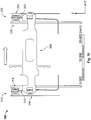
- Fig. 1 shows an exploded perspective view of an electromagnetic relay 100 according to an embodiment.
- the electromagnetic relay 100 is a three-state relay capable of switching between any of three different states for providing three different levels of operating voltage at the relay output terminals 110 and 120 based on the contact configuration and one or more potential voltage applied at each of the relay input terminals 130, 140, 150, 160.
- Each of the three operating states of the relay 100 correspond to a specific configuration of connections between contacts of a contact assembly 300 and can be switched to another configuration under the actuation of a magnetic actuator 200, as it will be explained below.
- the electromagnetic relay 100 may comprise a base 400 with features adapted to receive and fix the contact assembly 300 with the magnetic actuator 200 thereon, for e.g. by press-fit.
- the magnetic actuator 200 is designed with a shape and size suitable for fitting within the contact assembly 300.
- a perspective view of the electromagnetic relay 100 with the magnetic actuator 200, the contact assembly 300 and the base 400 in an assembled condition is shown in Fig. 2 .
- the electromagnetic relay 100 may also include a cover (not shown) for covering and protecting the contact assembly 300 and the magnetic actuator 200 in harsh environments.
- the base 400 and/or the cover may be made of a plastic material, such as LCP GF 30.
- the magnetic actuator 200 and the contact assembly 300 may be directly mounted on a PCB or inside a box of the appliance to be operated.
- the input control terminals 210, 220 of the magnetic actuator 200 and the relay terminals 110 - 140 protrude from a same side of the base 400 so as to facilitate electrical connections with external circuitry (not shown) from a same side of the relay 100.
- the magnetic actuator 200 is mechanically coupled to the contact assembly 300 for changing its contact configuration between any of three switching configurations via magnetic actuation in response to an input control signal applied at input terminals 210, 220 of the magnetic actuator 200.
- the contact assembly 300 provides a first operating state where the voltage input at the relay input terminals 130 and 160 is output with a given polarity, a second operating state where the voltage input at the relay input terminals 150 and 130 is output, i.e.
- the magnetic actuator 200 includes a rocking armature 230 that is pivotally supported on the magnetic actuator 200 at a center region 240 of the armature 230.
- the armature 230 can rotate in a clockwise and counter-clockwise direction about a rotation axis C that extends through the center region 240 under the actuation of a magnetic system 250 of the magnetic actuator 200, as it will be explained later.
- the armature 230 is preferably made of a single piece of rigid material and designed with two arms 232, 234 that extend in opposed directions on each side of the center region 240. As illustrated in more detail in Fig.
- the armature arms 232, 234 may have a symmetric shape and extend from the center region 240 with an inclination angle such that the rocking armature 230 does not have a flat shape but rather an angled double-wing shape with respect to the center region 240.
- the center region 240 then acts as a fulcrum about which the armature 230 rotates in the clockwise or counter-clockwise direction about the rotation axis C.
- the angled double-wing shape also provides an air separation gap between the tips of the armature arms 232, 234 and outer poles of the magnetic system 250 when the armature 230 is in a neutral position, as it will be explained later.
- the armature 230 may be fixed to a coil body 260 of the magnetic system 250 by a hinge spring 236 that is mounted on the center region 240 of the armature 230 and fixed to receiving features 262 provided in the coil body 260.
- the hinge spring 236 functions as a torsional spring that ensures mechanical contact of the armature with a core member of the magnetic system 250.
- the magnetic system 250 is designed to apply a magnetic force on at least one of the armature arms 232, 234 that causes the armature 230 to rotate about the rotation axis C from a neutral position to either a first operating position (for e.g. by rotating in a clockwise direction) or a second operating position (for e.g. by rotating in counter-clockwise direction).
- the magnetic system 250 comprises an electromagnet 270 responsible for creating a magnetic flux field in response to an input control signal supplied at the input control terminals 210, 220 for and which is responsible for the magnetic forces to be applied on the armature 230.
- the electromagnet 270 may be provided as a bobbin or a single coil that is wound around the coil body 250.
- the electromagnet 270 is oriented with respect to the armature 230 such that one of its end sides faces the armature 230, approximately centered with the armature center region 240, and its inner longitudinal axis L is approximately aligned in a direction transverse to the rotation axis C and passing through the center of mass of the armature 230.
- the magnetic system 260 includes a core member 280 that extends longitudinally across the inner side of the electromagnet 270 and at least two outer poles 292, 294 arranged on an outer side of the electromagnet 270.
- the core member 280 and the outer poles 292, 294 are made of soft magnetic materials so as to respectively concentrate the magnetic flux created by the electromagnet 270 along the magnetic flux paths defined by the core member 280 and the outer poles 292, 294 in the inner and outer sides of the electromagnet 270, respectively.
- Each of the outer pole 292, 294 extends adjacently along the electromagnet 270, preferably between the end facing the armature 230 and the opposed end of electromagnet 270.
- the outer poles 292, 294 and the core member 270 are provided as separate parts so as to provide two alternative magnetic paths for applying a resultant magnetic force on one arm or the other arm of the armature 230 depending on the direction of the magnetic flux field created by the electromagnet 270, as it will be explained later.
- the magnetic actuator 200 further includes at least two permanent magnets 296, 298.
- Each permanent magnet 296, 298 is arranged in a separation gap between a respective outer pole 292, 294 and the core member 270 and are provided with a magnetic polarization suitable for increasing or decreasing the magnetic resistance along the magnetic circuit branch formed by the core member 280, the permanent magnet 296 (or 298) and the respective outer pole 292 (or 294) depending on the direction of the magnetic flux created by the electromagnet 270.
- the permanent magnet 296 is arranged with a magnetic polarization that is the inverse of the magnetic polarization of the permanent magnet 298 arranged on the other branch of the magnetic circuit, i.e.
- the two permanent magnets 296, 298 produce sensitivity of the magnetic system 250 to the polarity of the electromagnet 270, so that when the electromagnet 270 is energized with a specific polarity, the different poles 292, 294 will exert attractive magnetic forces of different intensity on the armature arms 232, 234, respectively.
- a binary force is produced on the center hinge 250 of the armature 230 due to the differential between the magnetic forces exerted by the top ends of each outer pole 292, 294 on the respective armature arms 232, 234.
- the design of the magnetic circuit 250 can be optimized by providing a core member 280 with a T-shape that includes a longitudinal limb 282 adapted to be inserted along the longitudinal inner axis L of the electromagnet 270 and two transverse limbs 284, 286 that protrude from an end side of the longitudinal limb 282 and the electromagnet 270 on a side opposed to the armature 230.
- each outer pole 292, 294 may be designed so as to almost form a yoke with a U-shape when arranged around the electromagnet 270, but which are provided as separate elements so as to decouple the magnetic flux paths flowing through the outer poles 292, 294 from each other.
- each outer pole 292, 294 may be provided with similar L-shapes having a longitudinal arm and a transverse arm that substantially form a right angle with each other, the length of the longitudinal arm being suitable for extending at least along the entire longitudinal length of the electromagnet 270.
- the transverse arms are oriented towards the core member 280 and partially overlap the end side of the electromagnetic 270 opposed to the armature 230.
- Each permanent magnet 296, 298 is then arranged on the transverse arm of the respective outer pole 292, 294 and facing the core member 280.
- the electromagnet 270 When the electromagnet 270 is de-energized, the resultant magnetic force applied to the armature arms 232, 234 by the respective outer poles 292, 294 is null or negligible. In this state, the armature 230 is maintained in the neutral position, i.e. with similar air gap separation between the tips of the armature 232, 234 and the respective outer poles 292, 294, through the action of the hinge spring 250.
- Fig. 7 is a graphical representation of simulation results for the resultant magnetic force applied on the armature as a function of the air gap separation between an outer pole and the tip of the respective armature arm.
- the maximum intensity of the actuating force is reached at null separation distance between the outer pole and the armature arm (full contact between armature arm and outer pole) and progressively decreases with the increase on the separation distance, which is minimal when the armature reaches the neutral position.
- Fig. 8 The operation of switching the contact assembly 300 of the electromagnetic relay 100 among any of three switching states under the actuation of the magnetic actuator 200 will now be described with reference to Fig. 8 .
- one arm 232 of the armature 230 is mechanically coupled to a slidable coupler 500 positioned on a lateral side of the magnetic system 250.
- the slidable coupler 500 performs a linear movement along the longitudinal direction of the magnetic system 250, for e.g. rightwards (positive direction of Y-axis in Fig.
- the slidable coupler 500 has a main body 510 with an elongated form along the longitudinal direction (Y-axis) and a pair of legs 520, 522 provided at an intermediate position that extend transversely from each side of the longitudinal direction of the main body 510.
- the pair of legs 520, 522 include coupling features 530, 532 at each extremity for mechanically coupling with corresponding mating features 236, 238 provided in the armature arm 232.
- the slidable coupler 500 is mechanically coupled to the contact assembly 300 such as to switch configuration of contacts during its longitudinal movement.
- Fig. 9 shows a lateral view of the contact assembly 300 with two arrangements of contacts and the slidable coupler 500 in a neutral position.
- the contact assembly 300 includes a first arrangement of contacts 310 comprising a movable contact element 312 and two contact elements 314, 316 positioned on each side of the movable contact element 312.
- the contact elements 314, 316 are preferably stationary contacts that maintain their relative position with respect to the electromagnetic relay 100 in the assembled state, whereas the movable contact element 312 can be moved or switched between the contact elements 314, 316.
- the movable contact element 312 corresponds to a change-over (CO) terminal
- the stationary contact elements 314, 316 correspond to normally closed (NC) and normally opened (NO) terminals, respectively.
- the contact assembly 300 includes a second arrangement of contacts 320 that is located on a side of the magnetic actuator 200, opposite to side where the first arrangement of contacts 310 is placed when the electromagnetic relay 100 is assembled.
- the second arrangement of contacts 320 comprises a movable contact element 322 arranged between stationary contact elements 324, 326.
- the stationary contact elements 324, 326 correspond to normally closed and normally opened terminals and the movable contact element 322 to a change-over terminal adapted to come into electrical contact with either one of the stationary contact elements 324, 326.
- the movable and stationary contact elements are positioned with respect to each other within the respective contact arrangements 310, 320 and coupled by the slidable coupler 500 so as to obtain three different switching states of the contact assembly 300 as explained in the following with reference to Figs. 9 to 10 .
- Fig. 9 illustrates a case where the slidable coupler 500 is in the intermediate, neutral position and both movable contact elements 312, 322 are in a resting position, i.e. each of the movable contact elements 312, 322 is in electrical contact with the outer stationary contact element of the respective contact arrangement, i.e. with the stationary contact elements 314 and 324.
- the slidable coupler 500 exerts no contact pressure on the movable contact elements 312, 322.
- This switching state corresponds to the armature 230 being in the neutral position, such as illustrated in Fig. 6 .
- the contact assembly 300 may be made to switch from the neutral state to one of the first and second operating states of the electromagnetic relay 100 under the actuation of the armature 230 via the slidable coupler 500.
- one of the movable contact elements 312, 322 is made to change from its resting position, where it is in contact with one of the stationary contact elements of respective contact arrangement 310, 320, into a contact with the opposed stationary contact element, i.e. the stationary contact element positioned in the movement direction of the slidable coupler 500, while the other of movable contact elements 312, 322 remains in its resting position.
- Fig. 10 illustrates a case where a first switching state of the contact assembly 300 is achieved by displacing the slidable coupler 500 in a first movement direction (rightwards in Fig. 10 ) into a first position, thereby displacing the movable contact element 312 on the left side of the contact assembly 300 in the movement direction, from its resting, contact position with the outer stationary contact element 314 into a contact position with the inner stationary contact element 316.
- the movable contact element 322 located on the right side of the contact assembly 300 i.e. in the movement direction of the slidable coupler 500, remains in its resting position though being now pressed against the outer stationary contact element 324 by the slidable coupler 500.
- a second switching state is achieved when the slidable coupler 500 is moved in a movement direction opposed to the first movement direction, for e.g. leftwards, under the actuation of the armature 230 into a second position, at which the slidable coupler 500 presses each movable contact element 312, 322 against the respective stationary contact elements 314, 326 positioned leftwards from the movable contact elements 312, 322 (i.e. in the direction of movement of the slidable coupler 500).
- the stationary contact elements 314, 316, 324, 326 may be provided as rigid contact terminals extending in a direction approximately transverse to the direction of the linear movement of the slidable coupler 500. Contact pads may be added at the respective end parts for improving contact with movable contact elements 312, 322.
- the movable contact elements 312, 322 may be provided with a resilient body or connected by a spring to a support of the contact assembly 300 or the base 400 in order to reduce resistance against the movement induced by the slidable coupler 500.
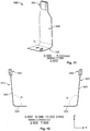
- Fig. 11 shows a configuration of the movable contact element 322 (or 312) having a flat base 330 for attaching or inserting to a support of the contact assembly 300 or the base 400 of the electromagnetic relay 100, and a resilient body 340 that extends almost vertically from the flat base 330 with an inclination angle a larger than 90°.
- the inclination angle ⁇ of the movable contact elements 312, 322 ensures that the movable contact elements 312, 322 are in stable electrical contact with the respective outer stationary contact elements 314, 326 when the relay is in the neutral state and the magnetic actuator 200 is not energized.
- other contact configurations may be envisaged in which both the movable and the stationary contact elements extend in parallel to each other.
- the resistance against movement applied by the movable contact elements 312, 322 on the slidable coupler 500 may be reduced by decoupling the stages when the slidable coupler 500 applies mechanical force on the movable contact elements 312 and 322, as explained below with reference to Figs. 13 - 15 .
- the contact pads of the stationary contact elements 314, 316, 324, and 326 are represented in Figs. 13 - 15 .
- Fig. 13 illustrates schematically the slidable coupler 500 in the neutral state with respect to the contact elements of the contact assembly 300.
- First and second pressure elements 540, 550 are provided on the left and right sides of the slidable coupler 500 for pushing the respective movable contact elements 312 or 322 from their respective neutral positions when the coupler 500 is moved rightwards or leftwards, respectively.
- the first and second pressure elements 540, 550 are positioned with respect to the respective movable contact elements 312 or 322 so as to leave an initial gap 560 between them when the slidable coupler 500 is in the neutral position.
- the slidable coupler 500 does not exert mechanical force on the movable contact element 312 or 322 in the neutral position.
- the respective first or second pressure element 540 or 550 will enter into contact with the respective movable contact element 312 or 322 only after the slidable coupler 500 is linearly displaced from the neutral position by a first traveling distance that approximately corresponds to the value of the initial gap 560.
- the first pressure feature 540 on the left side of the slidable coupler 500 contacts and starts exerting pressure on the left side of the movable contact element 312 only after the slidable coupler 500 has been displaced rightwards by a distance equal to the initial gap 560.
- the slidable coupler 500 is still not applying mechanical force on the movable contact element 322 on the left side of the contact assembly 300.
- the slidable coupler 500 also includes additional third and fourth pressure elements 542, 552 provided on the inner left and right sides of the slidable coupler 500.
- the pressure elements 542, 552 In the neutral position the pressure elements 542, 552 have a separation from the respective movable contact elements 312, 322 that corresponds to an overtravel distance 570 by which the slidable coupler 500 has to be additionally displaced for bringing the movable contact element 312 or 322 into contact with the opposed, inner stationary contact element 316 or 326.
- Fig. 15 illustrates the case where the movable contact element 312 is brought into contact with the inner stationary contact element 316 after the slidable coupler 500 has been further displaced rightwards by the overtravel distance 570.
- the pressure element 552 on the right side of the slidable coupler 500 exerts pressure onto the movable contact element 322, which helps to maintain the movable contact element 322 in electrical contact with the outer stationary contact element 324, and therefore improves resistance of the electrical connection against vibrations.
- the slidable coupler 500 is first linearly displaced by a distance corresponding to the initial gap 560 with reduced resistance from only one of the movable contact elements 312 or 322, and then by an overtravel distance 570 in the same movement direction for bringing the movable contact element 312 or 322 into contact with the opposed stationary contact element.
- the overall displacement of the slidable coupler 500 when switching from the neutral state to one of the first and second operating states corresponds to an overall distance approximately equal to equal to the initial gap 550 and the overtravel 570.
- the overtravel distance 570 is higher than the initial gap 550 for improving stability of the contacts in the three switching states.
- Fig. 16 shows a circuit diagram of a motor reverse application using a three-state relay 600 according to principles of the present invention for switching between any of a neutral state for stopping/halting the motor, a first state for driving the motor in given direction and a second state for reverting the direction of the motor movement.
- the three-state relay 600 has NO terminals 610 and NC terminals 620 that are respectively coupled to the positive and negative terminals of a power source, such as a battery.
- the movable CO terminals 630 are electrically coupled to the terminals of the motor 640 and remain in the resting position, i.e.
- the three-state relay 600 can be switched from the neutral state to any of two operating states for operating the motor 640 with direct or reverse rotation by supplying a single input signal from a signal source 660 and which is converted by a single driver 672 into an analogue signal with suitable polarity and intensity for causing a rotation of the relay armature in the direction associated with the desired motor rotation.
- Fig. 17 shows a circuit diagram of a headlight or fan application using the three-state relay 600 shown in Fig. 16 .
- the NO terminals 610 of the three-state relay 600 are not connected to the same positive terminal of a power source as in Fig. 16 but rather to respective potential voltages V1 and V2 so that two different power levels for driving the appliance can be achieved depending on whether one or the other of the CO terminals 630 is made to contact one or the other of the NO terminal 610.
- the neutral state is achieved when the CO terminals 630 are both switched to connect to the NC terminals 620.
- the concept described above allows yielding a three-state relay which can be switched under actuation of a single armature operable with a single inductive coil by simply reversing the sign of the input control signal fed to the single inductive coil.
- the contact configuration corresponding to the neutral configuration (off state) is achieved by de-energizing the single coil, and therefore, does not require additional excitation coils for reverting the armature to its neutral position.
- three switching states may be achieved with a single relay format that can be easily operated with a single control line, without requiring synchronization between multiple operation lines and complex circuitry.
- the present invention provides a magnetic actuator and electromagnetic relay with a compacter design and of simple operation.
- the magnets and other components of the magnetic actuator can be assembled by simple insertion or press fitting, and thereof, the assembly of the electromagnetic relay requires no welding or riveting.
Landscapes
- Physics & Mathematics (AREA)
- Electromagnetism (AREA)
- Engineering & Computer Science (AREA)
- Power Engineering (AREA)
- Electromagnets (AREA)
Abstract
Description
- The present invention relates to relays for general switching applications, and more particularly, to electromagnetic relays providing three switching states for automotive and/or appliances applications.
- Inductive circuit breakers, such as relays, are widely employed as switching devices in a variety of applications, such as automotive applications and electrical appliances. Single relays are conventionally used in applications that operate in only two states, for e.g. on and off states. Each relay state corresponds to a specific configuration of connections among the relay contacts, which can be changed or switched to another state or configuration in response to one or more control signals. Simple relays are generally operated by an inductive coil that actuates on a movable armature for switching on or off a contact with a terminal of a power source. Conventional change-over relays also provide two switching states by an arrangement of a change-over spring (CO terminal) and two stationary contact terminals, generally referred to as normally closed (NC) and normally open (NO), between which the CO terminal can be moved. The CO terminal is generally connected to a terminal of a motor or electrical appliance and is actuated by a magnetic system to switch contact to either the NO or NC terminals, which are respectively connected to the power source terminals. Both these type of relays can be operated with a single control line but are limited to only two relay states.
- In order to increase the number of possible relay states, hereinafter also referred to as switching states, two or more single relays may be combined. Conventional relays based on a combination of two independent relays are capable of yielding four independent switching states (or three switching states if some mechanical coupling between two switching states is added) but typically use two magnetic systems driven by two independent coils that can have the same or independent activation signals. Each relay is still controlled by an individual control line and an individual driver for converting a digital input control signal into an analogue signal for activating or deactivating the relay. Thus, the conventional double relay arrangement requires two mandatory control lines to control each relay independently, which implies synchronization between control lines, leading to a more complex circuit design and programming effort.
- Several motor and electrical appliance applications require relay designs capable of providing more than two relay states. Motor reverse requires at least three operating states for applying at the motor terminals one of: positive polarization (+/-) for motor motion in one direction, reversed polarization (-/+) for inverting the direction of motor motion, and halt/stop (-/- or +/+) for halting or stopping the motor. A double relay configuration based on two change-over relays is conventionally used in motor reverse applications, in which the motor rotates in a direction defined by the activated relay. When both relays are deactivated, both motor terminals are connected to the negative terminal of the power source (or ground potential), thereby stopping the motor motion and discharging the motor inductive system. However, the conventional double relay configuration also provides an additional fourth state that might not be necessary. In fact, the motor motion will also stop in the event that both relays are simultaneously activated, i.e. both motor terminals are connected to the same positive potential (+/+), however, in a slower manner since the inductive system will take more time to de-energize. Furthermore, as mentioned above, the double relay format has the drawback of requiring software handling and synchronization for switching the state of the individual relays simultaneously. This requires additional control lines for operating each relay, additional load as well as the necessary routing in comparison to single relay formats. More elements require more space and increase hardware and software complexity, as well as costs. These aspects are particularly important for motor applications, where relays are in general mounted in a PCB driver module or in a relay box.
- An electromagnetic relay for motor reverse applications that provides three switching states is described in published European patent application No.
16398001.4 - Other type of applications may also benefit from a three-state relay design, including applications which operate with three level power adjustment (e.g. off, minimum and maximum power), such as headlights, wipers or fans, and applications which require polarity reversal with in-between circuit energy drain.
- Hence, there is still a need for simple and flexible relay designs capable of yielding three switching states with reduced costs and number of components and requiring less complexity in circuit design and programming.
- The present invention has been made in view of the shortcomings and disadvantages of the prior art, and an object thereof is to provide a magnetic actuator for a three-state switching relay and an electromagnetic relay comprising same, which are capable of yielding three independent switching states with a compact and easy to control design, while providing improved robustness against vibrations.
- This object is solved by the subject matter of the independent claims. Advantageous embodiments of the present invention are subject matter of the dependent claims.
- The present invention provides a magnetic actuator for a three-state switching relay, comprising: an armature having two arms that extend laterally from a center region of the armature; and a magnetic system adapted to apply a magnetic force on at least one of the armature arms for causing the armature to rotate about its center region from a neutral position to any of a first operating position and a second operating position; wherein the magnetic system comprises: an electromagnet adapted to create a magnetic flux field based on an input control signal supplied by a control line, an end side of the electromagnet facing the armature; a core member extending longitudinally across an inner side of the electromagnet; at least two outer poles arranged on an outer side of the electromagnet, each outer pole extending adjacent to the electromagnet towards the end side facing the armature; and at least two permanent magnets, each permanent magnet being arranged in a separation gap between a respective outer pole and the core member and magnetically polarized with respect to the core member so that the core member, each outer pole and the respective permanent magnet form a respective path for the magnetic flux created by the electromagnet.
- According to an embodiment, the permanent magnets have different polarizations to create a differential in magnetic resistance between the respective magnetic flux paths; and the magnetic pole of each permanent magnet faces the core member with a sign opposite to the sign of the other permanent magnet pole.
- In a further embodiment, said magnetic resistance differential causes a differential between the magnetic forces applied by each outer pole on the respective armature arm that is adapted to rotate the armature towards the outer pole associated with the lower magnetic resistance path.
- In a further embodiment, the armature is rotatively coupled to the core member through a hinge spring mounted through the center region of the armature; the hinge spring is adapted to maintain the armature in the neutral position when the electromagnet is de-energized.
- In a further embodiment, each arm of the armature extends laterally away from the center region such that the cross-section of the armature has the shape of an angled double wing.
- In a further embodiment, the core member is configured with a T-shape having a longitudinal limb and two transverse limbs, the longitudinal limb being adapted to be inserted along the longitudinal inner axis of the electromagnet and each transverse limb being adapted to extend outwards from an end side of the longitudinal limb; and each permanent magnet being arranged between a respective transverse limb and a respective outer pole.
- In a further embodiment, each of the outer poles is designed with a L-shape including a longitudinal arm and a transverse arm that substantially form a right angle to each other, the outer poles being arranged outside the electromagnet with the respective longitudinal arms extending along the electromagnet longitudinal axis and the transverse arms extending inwards towards the core member; and each permanent magnet being arranged on the transverse arm of the respective outer pole and facing the core member.
- In a further embodiment, the electromagnet is formed by a single coil wounded in a same direction about the longitudinal inner axis such that the direction of the magnetic flux field created by the electromagnet is controlled by the sign of the input control signal; and/or each permanent magnet is a two-pole magnet.
- The invention further provides an electromagnetic relay, comprising: a magnetic actuator according to the invention, a slidable coupler mechanically coupled to the armature of the magnetic actuator and adapted to perform a linear movement when the armature is rotated from the neutral position to any of the first and second operating positions; and a contact assembly adapted to switch among any of three switching states under the actuation of the slidable coupler.
- In a further embodiment, the contact assembly comprises: a first arrangement of contacts comprising a movable contact element and at least one stationary contact element, the first arrangement of contacts being arranged on a first side of the magnetic actuator; wherein the slidable coupler includes a first pressure feature adapted to exert pressure on a side of the movable contact element during a linear movement of the slidable coupler from the neutral position towards a second side, opposed to the first side, after a first travelling distance, and a second pressure feature adapted to exert pressure on the opposed side of movable contact element during a linear movement of the slidable coupler from the neutral position towards the first side, after travelling a second travelling distance, and the second travelling distance is higher than the first travelling distance.
- In a further embodiment, the contact assembly further comprises: a second arrangement of contacts comprising a movable contact element and at least one stationary contact element, the second arrangement of contacts being arranged on the second side of the electromagnetic relay, opposite to the first arrangement of contacts; wherein the slidable coupler includes a third pressure feature adapted to exert pressure on the movable contact element of the second arrangement during the linear movement from the neutral position towards the second side, after travelling the second travelling distance, and a fourth pressure feature adapted to exert pressure on the movable contact element of the second arrangement during the linear movement from the neutral position towards the first side, after travelling the first travelling distance.
- In a further embodiment, each of the first and second arrangements of contacts comprises first and second stationary contact elements, the first stationary contact elements corresponding to outer stationary contact elements and the second stationary contact elements corresponding to inner stationary contact elements with respect to the movable contact elements of the first and second arrangements of contacts.
- In a further embodiment, the slidable coupler is adapted to make each movable contact element to come into contact with the respective first or second stationary contact depending on the movement direction of the slidable coupler, such that: a first switching state is achieved when the slidable coupler is moved, in a first movement direction, from the neutral position into a first position at which the slidable coupler presses each movable contact element against the respective stationary contact elements on the side defined by the slidable coupler movement direction; a second switching state is achieved when the slidable coupler is moved, in a second movement direction opposed to the first movement direction, from the neutral position into a second position, at which the slidable coupler presses each movable contact element against the respective stationary contact elements on the side defined by the second movement direction; and third switching state is achieved when the slidable coupler is in an intermediate position corresponding to the neutral position at which the slidable coupler exerts no pressure on each of the movable contact elements.
- In a further embodiment, the movable contact element is a change-over terminal, and the first stationary contact elements are normally closed terminal and the second stationary contact elements are normally opened terminal.
- In a further embodiment, the first and second stationary contact elements extend in a direction approximately transverse to the direction of the linear movement of the slidable coupler, and the movable contact element extends in a direction that makes a non-zero angle with the direction first and second stationary contact elements and such that an end part of the movable contact element rests in contact with an end part of the first stationary contact element when the slidable coupler is in the neutral position.
- The accompanying drawings are incorporated into and form a part of the specification for the purpose of explaining the principles of the invention. The drawings are not to be construed as limiting the invention to only the illustrated and described examples of how the invention can be made and used.
- Further features and advantages will become apparent from the following and more detailed description of the invention as illustrated in the accompanying drawings, in which:
-
Fig. 1 is an exploded perspective view of an electromagnetic relay according to an embodiment of the present invention; -
Fig. 2 is a perspective view of the electromagnetic relay shown inFig. 1 in an assembled condition; -
Fig. 3 is a schematic perspective view of a magnetic actuator of the electromagnetic relay according to an embodiment; -
Fig. 4 shows an exploded perspective view of an armature and hinge springe of the magnetic actuator shown inFig. 3 ; -
Fig. 5 is a schematic perspective view of a coil body of the magnetic actuator shown inFig. 3 ; -
Fig. 6 shows schematically a cross-section view across the plane XY of the magnetic actuator illustrated inFig. 3 with the armature in a neutral position; -
Fig. 7 is a graphical representation of simulation results of the resultant magnetic force applied on the armature as a function of the air gap separation between an outer pole and the tip of the respective armature arm; -
Fig. 8 shows schematically a cross sectional view of an electromagnetic relay having a magnetic actuator coupled to a contact assembly according to an embodiment; and -
Fig. 9 is a lateral view of a contact assembly having two arrangements of contacts and a slidable coupler in a neutral position; -
Fig. 10 is a lateral view of the contact assembly and slidable coupler in a first operating position; -
Fig. 11 is a perspective view of a movable contact element according to an embodiment; -
Fig. 12 is a perspective view of a movable contact element according to an embodiment; -
Fig. 13 illustrates schematically the slidable coupler in the neutral state with respect to the contact elements of the contact assembly; -
Fig. 14 illustrates schematically the slidable coupler and the contact elements of the contact assembly in an intermediate state between the neutral state and a first operating state (moving rightwards); -
Fig. 15 illustrates schematically the slidable coupler and the contact elements of the contact assembly in the first operating state; -
Fig. 16 shows a circuit diagram of a motor reverse application using the electromagnetic relay of the present invention for switching between any of three switching states; and -
Fig. 17 shows a circuit diagram of a headlight or fan application using the electromagnetic relay of the present invention for switching between any of three switching states. - The present invention will now be more fully described hereinafter with reference to the accompanying drawings, in which exemplary embodiments of the invention are shown. The present invention may, however, be embodied in many different forms and should not be construed as limited to the embodiments set forth herein. Rather, these embodiments are provided so that the disclosure will be thorough and complete, and will fully convey the scope of the invention to those skilled in the art. Like numbers refer to like elements throughout.
- It should be noted that the following description assumes that, in the figures, the longitudinal direction is the direction of the illustrated Y axis, a movement in the positive or negative direction of the Y axis being referred to as a longitudinal movement to the right or to the left, respectively. Further, the following description assumes that the vertical direction is a direction parallel to the direction of the Z axis in the figures, the upward direction corresponding to a +Z direction and the downward direction to a -Z direction. Furthermore, a plane parallel to the plane defined by the X and Y axes in the figures is referred to as an horizontal plane in the following description.
-
Fig. 1 shows an exploded perspective view of anelectromagnetic relay 100 according to an embodiment. Theelectromagnetic relay 100 is a three-state relay capable of switching between any of three different states for providing three different levels of operating voltage at therelay output terminals relay input terminals relay 100 correspond to a specific configuration of connections between contacts of acontact assembly 300 and can be switched to another configuration under the actuation of amagnetic actuator 200, as it will be explained below. - The
electromagnetic relay 100 may comprise a base 400 with features adapted to receive and fix thecontact assembly 300 with themagnetic actuator 200 thereon, for e.g. by press-fit. Themagnetic actuator 200 is designed with a shape and size suitable for fitting within thecontact assembly 300. A perspective view of theelectromagnetic relay 100 with themagnetic actuator 200, thecontact assembly 300 and the base 400 in an assembled condition is shown inFig. 2 . In this case, theelectromagnetic relay 100 may also include a cover (not shown) for covering and protecting thecontact assembly 300 and themagnetic actuator 200 in harsh environments. Thebase 400 and/or the cover may be made of a plastic material, such as LCP GF 30. Alternatively, themagnetic actuator 200 and thecontact assembly 300 may be directly mounted on a PCB or inside a box of the appliance to be operated. As shown inFig. 2 , theinput control terminals magnetic actuator 200 and the relay terminals 110 - 140 (which coincide with contact terminals of the contact assembly 300) protrude from a same side of the base 400 so as to facilitate electrical connections with external circuitry (not shown) from a same side of therelay 100. - The
magnetic actuator 200 is mechanically coupled to thecontact assembly 300 for changing its contact configuration between any of three switching configurations via magnetic actuation in response to an input control signal applied atinput terminals magnetic actuator 200. For instance, in case theinput terminals 130, 140 are both connected to a same terminal of a power source (e.g. - terminal) and theinput terminals contact assembly 300 provides a first operating state where the voltage input at therelay input terminals relay input terminals terminals relay terminals relay input terminals magnetic actuator 200 will now be described with reference toFigs. 3 - 6 . - Referring to
Fig. 3 , themagnetic actuator 200 includes a rockingarmature 230 that is pivotally supported on themagnetic actuator 200 at acenter region 240 of thearmature 230. Thearmature 230 can rotate in a clockwise and counter-clockwise direction about a rotation axis C that extends through thecenter region 240 under the actuation of a magnetic system 250 of themagnetic actuator 200, as it will be explained later. Thearmature 230 is preferably made of a single piece of rigid material and designed with twoarms center region 240. As illustrated in more detail inFig. 4 , thearmature arms center region 240 with an inclination angle such that the rockingarmature 230 does not have a flat shape but rather an angled double-wing shape with respect to thecenter region 240. Thecenter region 240 then acts as a fulcrum about which thearmature 230 rotates in the clockwise or counter-clockwise direction about the rotation axis C. The angled double-wing shape also provides an air separation gap between the tips of thearmature arms armature 230 is in a neutral position, as it will be explained later. Thearmature 230 may be fixed to acoil body 260 of the magnetic system 250 by ahinge spring 236 that is mounted on thecenter region 240 of thearmature 230 and fixed to receivingfeatures 262 provided in thecoil body 260. Thehinge spring 236 functions as a torsional spring that ensures mechanical contact of the armature with a core member of the magnetic system 250. - The magnetic system 250 is designed to apply a magnetic force on at least one of the
armature arms armature 230 to rotate about the rotation axis C from a neutral position to either a first operating position (for e.g. by rotating in a clockwise direction) or a second operating position (for e.g. by rotating in counter-clockwise direction). Referring toFig. 6 , the magnetic system 250 comprises anelectromagnet 270 responsible for creating a magnetic flux field in response to an input control signal supplied at theinput control terminals armature 230. Theelectromagnet 270 may be provided as a bobbin or a single coil that is wound around the coil body 250. Theelectromagnet 270 is oriented with respect to thearmature 230 such that one of its end sides faces thearmature 230, approximately centered with thearmature center region 240, and its inner longitudinal axis L is approximately aligned in a direction transverse to the rotation axis C and passing through the center of mass of thearmature 230. - In addition, the
magnetic system 260 includes acore member 280 that extends longitudinally across the inner side of theelectromagnet 270 and at least twoouter poles electromagnet 270. Thecore member 280 and theouter poles electromagnet 270 along the magnetic flux paths defined by thecore member 280 and theouter poles electromagnet 270, respectively. - Each of the
outer pole electromagnet 270, preferably between the end facing thearmature 230 and the opposed end ofelectromagnet 270. - The
outer poles core member 270 are provided as separate parts so as to provide two alternative magnetic paths for applying a resultant magnetic force on one arm or the other arm of thearmature 230 depending on the direction of the magnetic flux field created by theelectromagnet 270, as it will be explained later. In order to magnetically couple the core member to theouter pole magnetic actuator 200 further includes at least twopermanent magnets permanent magnet outer pole core member 270 and are provided with a magnetic polarization suitable for increasing or decreasing the magnetic resistance along the magnetic circuit branch formed by thecore member 280, the permanent magnet 296 (or 298) and the respective outer pole 292 (or 294) depending on the direction of the magnetic flux created by theelectromagnet 270. Moreover, on one branch of the magnet flux circuit, for e.g. along theouter pole 292 andcore member 280, thepermanent magnet 296 is arranged with a magnetic polarization that is the inverse of the magnetic polarization of thepermanent magnet 298 arranged on the other branch of the magnetic circuit, i.e. alongouter pole 294 and thecore member 280, so that the magnetic path through which the magnetic force is primarily applied to thearmature 230 becomes automatically selected by the magnetic circuit branch that offers the lowest magnetic resistance to the direction of the magnetic flux created by theelectromagnet 270, and therefore, by the sign of the input control signal supplied to theinput terminals permanent magnets electromagnet 270, so that when theelectromagnet 270 is energized with a specific polarity, thedifferent poles armature arms armature 230 due to the differential between the magnetic forces exerted by the top ends of eachouter pole respective armature arms - The design of the magnetic circuit 250 can be optimized by providing a
core member 280 with a T-shape that includes a longitudinal limb 282 adapted to be inserted along the longitudinal inner axis L of theelectromagnet 270 and twotransverse limbs electromagnet 270 on a side opposed to thearmature 230. In addition, eachouter pole electromagnet 270, but which are provided as separate elements so as to decouple the magnetic flux paths flowing through theouter poles outer pole electromagnet 270. The transverse arms are oriented towards thecore member 280 and partially overlap the end side of the electromagnetic 270 opposed to thearmature 230. Eachpermanent magnet outer pole core member 280. - When the
electromagnet 270 is de-energized, the resultant magnetic force applied to thearmature arms outer poles armature 230 is maintained in the neutral position, i.e. with similar air gap separation between the tips of thearmature outer poles -
Fig. 7 is a graphical representation of simulation results for the resultant magnetic force applied on the armature as a function of the air gap separation between an outer pole and the tip of the respective armature arm. The maximum intensity of the actuating force is reached at null separation distance between the outer pole and the armature arm (full contact between armature arm and outer pole) and progressively decreases with the increase on the separation distance, which is minimal when the armature reaches the neutral position. - The operation of switching the
contact assembly 300 of theelectromagnetic relay 100 among any of three switching states under the actuation of themagnetic actuator 200 will now be described with reference toFig. 8 . As shown inFig. 8 , onearm 232 of thearmature 230 is mechanically coupled to aslidable coupler 500 positioned on a lateral side of the magnetic system 250. Under mechanical actuation from thearmature 230, theslidable coupler 500 performs a linear movement along the longitudinal direction of the magnetic system 250, for e.g. rightwards (positive direction of Y-axis inFig. 8 ) when the armature rotates counter-clockwise from the neutral position towards theouter pole 292 of the magnetic system 250 due to the magnetic force applied via the respective magnetic circuit branch exceeding the magnetic force applied by theouter pole 294 of the opposed branch. The rotation of thearmature 230 from the neutral position in the clockwise direction results in theslidable coupler 500 being moved to the opposed side, i.e. leftwards (negative direction of Y-axis inFig. 8 ). - As shown in
Fig. 2 , theslidable coupler 500 has amain body 510 with an elongated form along the longitudinal direction (Y-axis) and a pair oflegs main body 510. The pair oflegs armature arm 232. As a result of this mechanical coupling, a rotation movement of thearmature 230 about the rotation axis C is transformed into a linear movement of theslidable coupler 500 in the longitudinal direction. - On the other hand, the
slidable coupler 500 is mechanically coupled to thecontact assembly 300 such as to switch configuration of contacts during its longitudinal movement. -
Fig. 9 shows a lateral view of thecontact assembly 300 with two arrangements of contacts and theslidable coupler 500 in a neutral position. Thecontact assembly 300 includes a first arrangement ofcontacts 310 comprising amovable contact element 312 and twocontact elements movable contact element 312. Thecontact elements electromagnetic relay 100 in the assembled state, whereas themovable contact element 312 can be moved or switched between thecontact elements movable contact element 312 corresponds to a change-over (CO) terminal, and thestationary contact elements - In addition, the
contact assembly 300 includes a second arrangement ofcontacts 320 that is located on a side of themagnetic actuator 200, opposite to side where the first arrangement ofcontacts 310 is placed when theelectromagnetic relay 100 is assembled. The second arrangement ofcontacts 320 comprises amovable contact element 322 arranged betweenstationary contact elements contacts 310, thestationary contact elements movable contact element 322 to a change-over terminal adapted to come into electrical contact with either one of thestationary contact elements - The movable and stationary contact elements are positioned with respect to each other within the
respective contact arrangements slidable coupler 500 so as to obtain three different switching states of thecontact assembly 300 as explained in the following with reference toFigs. 9 to 10 . -
Fig. 9 illustrates a case where theslidable coupler 500 is in the intermediate, neutral position and bothmovable contact elements movable contact elements stationary contact elements slidable coupler 500 exerts no contact pressure on themovable contact elements armature 230 being in the neutral position, such as illustrated inFig. 6 . - The
contact assembly 300 may be made to switch from the neutral state to one of the first and second operating states of theelectromagnetic relay 100 under the actuation of thearmature 230 via theslidable coupler 500. Depending on movement direction of theslidable coupler 500, one of themovable contact elements respective contact arrangement slidable coupler 500, while the other ofmovable contact elements -
Fig. 10 illustrates a case where a first switching state of thecontact assembly 300 is achieved by displacing theslidable coupler 500 in a first movement direction (rightwards inFig. 10 ) into a first position, thereby displacing themovable contact element 312 on the left side of thecontact assembly 300 in the movement direction, from its resting, contact position with the outerstationary contact element 314 into a contact position with the innerstationary contact element 316. At the same time, themovable contact element 322 located on the right side of thecontact assembly 300, i.e. in the movement direction of theslidable coupler 500, remains in its resting position though being now pressed against the outerstationary contact element 324 by theslidable coupler 500. Similarly, a second switching state is achieved when theslidable coupler 500 is moved in a movement direction opposed to the first movement direction, for e.g. leftwards, under the actuation of thearmature 230 into a second position, at which theslidable coupler 500 presses eachmovable contact element stationary contact elements movable contact elements 312, 322 (i.e. in the direction of movement of the slidable coupler 500). - The
stationary contact elements slidable coupler 500. Contact pads may be added at the respective end parts for improving contact withmovable contact elements - The
movable contact elements contact assembly 300 or the base 400 in order to reduce resistance against the movement induced by theslidable coupler 500.Fig. 11 shows a configuration of the movable contact element 322 (or 312) having aflat base 330 for attaching or inserting to a support of thecontact assembly 300 or thebase 400 of theelectromagnetic relay 100, and aresilient body 340 that extends almost vertically from theflat base 330 with an inclination angle a larger than 90°. The inclination angle α of themovable contact elements movable contact elements stationary contact elements magnetic actuator 200 is not energized. However, other contact configurations may be envisaged in which both the movable and the stationary contact elements extend in parallel to each other. - The resistance against movement applied by the
movable contact elements slidable coupler 500 may be reduced by decoupling the stages when theslidable coupler 500 applies mechanical force on themovable contact elements Figs. 13 - 15 . For simplicity, only the contact pads of thestationary contact elements Figs. 13 - 15 . -
Fig. 13 illustrates schematically theslidable coupler 500 in the neutral state with respect to the contact elements of thecontact assembly 300. First andsecond pressure elements slidable coupler 500 for pushing the respectivemovable contact elements coupler 500 is moved rightwards or leftwards, respectively. The first andsecond pressure elements movable contact elements initial gap 560 between them when theslidable coupler 500 is in the neutral position. As a consequence, theslidable coupler 500 does not exert mechanical force on themovable contact element - During the linear movement of the
slidable coupler 500, the respective first orsecond pressure element movable contact element slidable coupler 500 is linearly displaced from the neutral position by a first traveling distance that approximately corresponds to the value of theinitial gap 560. As illustrated inFig. 14 , thefirst pressure feature 540 on the left side of theslidable coupler 500 contacts and starts exerting pressure on the left side of themovable contact element 312 only after theslidable coupler 500 has been displaced rightwards by a distance equal to theinitial gap 560. At this intermediate stage, theslidable coupler 500 is still not applying mechanical force on themovable contact element 322 on the left side of thecontact assembly 300. - The
slidable coupler 500 also includes additional third andfourth pressure elements slidable coupler 500. In the neutral position thepressure elements movable contact elements overtravel distance 570 by which theslidable coupler 500 has to be additionally displaced for bringing themovable contact element stationary contact element Fig. 15 illustrates the case where themovable contact element 312 is brought into contact with the innerstationary contact element 316 after theslidable coupler 500 has been further displaced rightwards by theovertravel distance 570. At this time, thepressure element 552 on the right side of theslidable coupler 500 exerts pressure onto themovable contact element 322, which helps to maintain themovable contact element 322 in electrical contact with the outerstationary contact element 324, and therefore improves resistance of the electrical connection against vibrations. As a result, for switching themovable contact element slidable coupler 500 is first linearly displaced by a distance corresponding to theinitial gap 560 with reduced resistance from only one of themovable contact elements overtravel distance 570 in the same movement direction for bringing themovable contact element slidable coupler 500 when switching from the neutral state to one of the first and second operating states corresponds to an overall distance approximately equal to equal to theinitial gap 550 and theovertravel 570. Preferably, theovertravel distance 570 is higher than theinitial gap 550 for improving stability of the contacts in the three switching states. -
Fig. 16 shows a circuit diagram of a motor reverse application using a three-state relay 600 according to principles of the present invention for switching between any of a neutral state for stopping/halting the motor, a first state for driving the motor in given direction and a second state for reverting the direction of the motor movement. In the illustrated configuration, the three-state relay 600 has NOterminals 610 andNC terminals 620 that are respectively coupled to the positive and negative terminals of a power source, such as a battery. Themovable CO terminals 630 are electrically coupled to the terminals of themotor 640 and remain in the resting position, i.e. in contact with the NC terminals, when therelay coil 650 is not energized, which corresponds to the contact configuration for stopping or halting the motor (neutral state). The three-state relay 600 can be switched from the neutral state to any of two operating states for operating themotor 640 with direct or reverse rotation by supplying a single input signal from asignal source 660 and which is converted by a single driver 672 into an analogue signal with suitable polarity and intensity for causing a rotation of the relay armature in the direction associated with the desired motor rotation. -
Fig. 17 shows a circuit diagram of a headlight or fan application using the three-state relay 600 shown inFig. 16 . In this application, theNO terminals 610 of the three-state relay 600 are not connected to the same positive terminal of a power source as inFig. 16 but rather to respective potential voltages V1 and V2 so that two different power levels for driving the appliance can be achieved depending on whether one or the other of theCO terminals 630 is made to contact one or the other of theNO terminal 610. Similarly to the operation shown inFig. 16 , the neutral state is achieved when theCO terminals 630 are both switched to connect to theNC terminals 620. - In conclusion, in contrast to double-armature and/or double magnetic systems of conventional relays, the concept described above allows yielding a three-state relay which can be switched under actuation of a single armature operable with a single inductive coil by simply reversing the sign of the input control signal fed to the single inductive coil. Moreover, the contact configuration corresponding to the neutral configuration (off state) is achieved by de-energizing the single coil, and therefore, does not require additional excitation coils for reverting the armature to its neutral position. As a result, three switching states may be achieved with a single relay format that can be easily operated with a single control line, without requiring synchronization between multiple operation lines and complex circuitry. Furthermore, by replacing the usage of two armatures for one, the present invention provides a magnetic actuator and electromagnetic relay with a compacter design and of simple operation. In addition, the magnets and other components of the magnetic actuator can be assembled by simple insertion or press fitting, and thereof, the assembly of the electromagnetic relay requires no welding or riveting.
- Although certain features of the above exemplary embodiments may have been eventually described using terms such as "top", "bottom", and "upper", "left" or "right", these terms are used for the purpose of facilitating the description of the respective features and their relative orientation within the electromagnetic relay only and should not be construed as limiting the claimed invention or any of its components to a particular spatial orientation.
-
- 100
- electromagnetic relay
- 110, 120
- relay output terminals
- 130, 140, 150, 160
- relay input terminals
- 200
- magnetic actuator
- 210, 220
- input terminals of magnetic actuator
- 230
- rocking armature
- 232, 234
- armature arms
- 236, 238
- mating features
- 240
- center region
- C
- rotation axis
- L
- inner longitudinal axis of electromagnet
- 250
- magnetic system
- 260
- coil body
- 262
- receiving features
- 270
- electromagnet
- 280
- core member
- 282
- longitudinal limb
- 284, 286
- transverse limbs
- 292, 294
- outer poles
- 296, 298
- permanent magnets
- 300
- contact assembly
- 310
- 1st arrangement of contacts
- 312
- movable contact element
- 314, 316
- stationary contact elements
- 320
- 2nd arrangement of contacts
- 322
- movable contact element
- 324, 326
- stationary contact elements
- 330
- flat base of movable contact element
- 340
- resilient body of movable contacts element
- 350
- contact pad of movable contact element
- α
- inclination angle of movable contact element
- 400
- base
- 500
- slidable coupler
- 510
- main body of slidable coupler
- 520, 522
- coupling legs
- 530, 532
- coupling features
- 540, 542
- pressure features on left side
- 550, 552
- pressure features on right-side
- 560
- initial gap
- 570
- overtravel
- 600
- three-state relay
- 610
- NO terminals
- 620
- NC terminals
- 630
- CO terminals
- 640
- motor
- 650
- inductive coil
- 660
- signal source
- 670
- driver
Claims (15)
- A magnetic actuator for a three-state switching relay, comprising:an armature having two arms that extend laterally from a center region of the armature; anda magnetic system adapted to apply a magnetic force on at least one of the armature arms for causing the armature to rotate about its center region from a neutral position to any of a first operating position and a second operating position;wherein the magnetic system comprises:an electromagnet adapted to create a magnetic flux field based on an input control signal supplied by a control line, an end side of the electromagnet facing the armature;a core member extending longitudinally across an inner side of the electromagnet;at least two outer poles arranged on an outer side of the electromagnet, each outer pole extending adjacent to the electromagnet towards the end side facing the armature; andat least two permanent magnets, each permanent magnet being arranged in a separation gap between a respective outer pole and the core member and magnetically polarized with respect to the core member so that the core member, each outer pole and the respective permanent magnet form a respective path for the magnetic flux created by the electromagnet.
- A magnetic actuator according to claim 1, wherein
the permanent magnets have different polarizations to create a differential in magnetic resistance between the respective magnetic flux paths;
the magnetic pole of each permanent magnet faces the core member with a sign opposite to the sign of the other permanent magnet pole. - A magnetic actuator according to claim 2, wherein said magnetic resistance differential causes a differential between the magnetic forces applied by each outer pole on the respective armature arm that is adapted to rotate the armature towards the outer pole associated with the lower magnetic resistance path.
- A magnetic actuator according to any one of claims 1 to 3, wherein
the armature is rotatively coupled to the core member through a hinge spring mounted through the center region of the armature;
the hinge spring is adapted to maintain the armature in the neutral position when the electromagnet is de-energized. - A magnetic actuator according to any one of claims 1 to 4, wherein
each arm of the armature extends laterally away from the center region such that the cross-section of the armature has the shape of an angled double wing. - A magnetic actuator according to any one of claims 1 to 5, wherein
the core member is configured with a T-shape having a longitudinal limb and two transverse limbs, the longitudinal limb being adapted to be inserted along the longitudinal inner axis of the electromagnet and each transverse limb being adapted to extend outwards from an end side of the longitudinal limb; and
each permanent magnet being arranged between a respective transverse limb and a respective outer pole. - A magnetic actuator according to any one of claims 1 to 6, wherein
each of the outer poles is designed with a L-shape including a longitudinal arm and a transverse arm that substantially form a right angle to each other, the outer poles being arranged outside the electromagnet with the respective longitudinal arms extending along the electromagnet longitudinal axis and the transverse arms extending inwards towards the core member; and
each permanent magnet being arranged on the transverse arm of the respective outer pole and facing the core member. - A magnetic actuator according to any one of claims 1 to 7, wherein
the electromagnet is formed by a single coil wounded in a same direction about the longitudinal inner axis such that the direction of the magnetic flux field created by the electromagnet is controlled by the sign of the input control signal; and/or
each permanent magnet is a two-pole magnet. - An electromagnetic relay, comprising:a magnetic actuator according to any one of claims 1 to 8;a slidable coupler mechanically coupled to the armature of the magnetic actuator and adapted to perform a linear movement when the armature is rotated from the neutral position to any of the first and second operating positions; anda contact assembly adapted to switch among any of three switching states under the actuation of the slidable coupler.
- An electromagnetic relay according to claim 9, wherein the contact assembly comprises:a first arrangement of contacts comprising a movable contact element and at least one stationary contact element, the first arrangement of contacts being arranged on a first side of the magnetic actuator; whereinthe slidable coupler includes a first pressure feature adapted to exert pressure on a side of the movable contact element during a linear movement of the slidable coupler from the neutral position towards a second side, opposed to the first side, after a first travelling distance, and a second pressure feature adapted to exert pressure on the opposed side of movable contact element during a linear movement of the slidable coupler from the neutral position towards the first side, after travelling a second travelling distance, andthe second travelling distance is higher than the first travelling distance.
- An electromagnetic relay according to claim 10, wherein the contact assembly further comprises:a second arrangement of contacts comprising a movable contact element and at least one stationary contact element, the second arrangement of contacts being arranged on the second side of the electromagnetic relay, opposite to the first arrangement of contacts; whereinthe slidable coupler includes a third pressure feature adapted to exert pressure on the movable contact element of the second arrangement during the linear movement from the neutral position towards the second side, after travelling the second travelling distance, and a fourth pressure feature adapted to exert pressure on the movable contact element of the second arrangement during the linear movement from the neutral position towards the first side, after travelling the first travelling distance.
- An electromagnetic relay according to claim 11, wherein
each of the first and second arrangements of contacts comprises first and second stationary contact elements,
the first stationary contact elements corresponding to outer stationary contact elements and the second stationary contact elements corresponding to inner stationary contact elements with respect to the movable contact elements of the first and second arrangements of contacts. - An electromagnetic relay according to claim 12, wherein:
the slidable coupler is adapted to make each movable contact element to come into contact with the respective first or second stationary contact depending on the movement direction of the slidable, such that:a first switching state is achieved when the slidable coupler is moved, in a first movement direction, from the neutral position into a first position at which the slidable coupler presses each movable contact element against the respective stationary contact elements on the side defined by the slidable coupler movement direction;a second switching state is achieved when the slidable coupler is moved, in a second movement direction opposed to the first movement direction, from the neutral position into a second position, at which the slidable coupler presses each movable contact element against the respective stationary contact elements on the side defined by the second movement direction; anda third switching state is achieved when the slidable coupler is in an intermediate position corresponding to the neutral position at which the slidable coupler exerts no pressure on each of the movable contact elements. - An electromagnetic relay according to any of claims 10 to 13, wherein
the movable contact element is a change-over terminal, and
the first stationary contact elements are normally closed terminal and the second stationary contact elements are normally opened terminal. - An electromagnetic relay according to claim 14, wherein:the first and second stationary contact elements extend in a direction approximately transverse to the direction of the linear movement of the slidable coupler, andthe movable contact element extends in a direction that makes a non-zero angle with the direction first and second stationary contact elements and such that an end part of the movable contact element rests in contact with an end part of the first stationary contact element when the slidable coupler is in the neutral position.
Priority Applications (2)
| Application Number | Priority Date | Filing Date | Title |
|---|---|---|---|
| EP19398001.8A EP3678158B1 (en) | 2019-01-04 | 2019-01-04 | Magnetic actuator and electromagnetic relay |
| EP19398017.4A EP3678159B1 (en) | 2019-01-04 | 2019-12-20 | Magnetic actuator and electromagnetic relay |
Applications Claiming Priority (1)
| Application Number | Priority Date | Filing Date | Title |
|---|---|---|---|
| EP19398001.8A EP3678158B1 (en) | 2019-01-04 | 2019-01-04 | Magnetic actuator and electromagnetic relay |
Publications (2)
| Publication Number | Publication Date |
|---|---|
| EP3678158A1 true EP3678158A1 (en) | 2020-07-08 |
| EP3678158B1 EP3678158B1 (en) | 2021-07-21 |
Family
ID=65023836
Family Applications (2)
| Application Number | Title | Priority Date | Filing Date |
|---|---|---|---|
| EP19398001.8A Active EP3678158B1 (en) | 2019-01-04 | 2019-01-04 | Magnetic actuator and electromagnetic relay |
| EP19398017.4A Active EP3678159B1 (en) | 2019-01-04 | 2019-12-20 | Magnetic actuator and electromagnetic relay |
Family Applications After (1)
| Application Number | Title | Priority Date | Filing Date |
|---|---|---|---|
| EP19398017.4A Active EP3678159B1 (en) | 2019-01-04 | 2019-12-20 | Magnetic actuator and electromagnetic relay |
Country Status (1)
| Country | Link |
|---|---|
| EP (2) | EP3678158B1 (en) |
Citations (5)
| Publication number | Priority date | Publication date | Assignee | Title |
|---|---|---|---|---|
| US3621419A (en) * | 1970-02-19 | 1971-11-16 | Leach Corp | Polarized latch relay |
| JPS5268952A (en) * | 1975-12-05 | 1977-06-08 | Matsushita Electric Works Ltd | Polar relay |
| JPH06283088A (en) * | 1993-03-26 | 1994-10-07 | Matsushita Electric Works Ltd | Electromagnetic relay |
| EP3211653A1 (en) * | 2016-02-23 | 2017-08-30 | Tyco Electronics Componentes Electromecanicos Lda | Electromagnetic relay for three switching positions |
| WO2018050861A1 (en) * | 2016-09-15 | 2018-03-22 | Fluid Automation Systems S.A. | Electromagnetic actuator with rocking armature |
Family Cites Families (1)
| Publication number | Priority date | Publication date | Assignee | Title |
|---|---|---|---|---|
| AU1461666A (en) * | 1967-08-14 | 1969-02-20 | Electro-mechanical bi-stable motive unit |
-
2019
- 2019-01-04 EP EP19398001.8A patent/EP3678158B1/en active Active
- 2019-12-20 EP EP19398017.4A patent/EP3678159B1/en active Active
Patent Citations (5)
| Publication number | Priority date | Publication date | Assignee | Title |
|---|---|---|---|---|
| US3621419A (en) * | 1970-02-19 | 1971-11-16 | Leach Corp | Polarized latch relay |
| JPS5268952A (en) * | 1975-12-05 | 1977-06-08 | Matsushita Electric Works Ltd | Polar relay |
| JPH06283088A (en) * | 1993-03-26 | 1994-10-07 | Matsushita Electric Works Ltd | Electromagnetic relay |
| EP3211653A1 (en) * | 2016-02-23 | 2017-08-30 | Tyco Electronics Componentes Electromecanicos Lda | Electromagnetic relay for three switching positions |
| WO2018050861A1 (en) * | 2016-09-15 | 2018-03-22 | Fluid Automation Systems S.A. | Electromagnetic actuator with rocking armature |
Also Published As
| Publication number | Publication date |
|---|---|
| EP3678159A1 (en) | 2020-07-08 |
| EP3678158B1 (en) | 2021-07-21 |
| EP3678159B1 (en) | 2021-10-13 |
Similar Documents
| Publication | Publication Date | Title |
|---|---|---|
| KR101592183B1 (en) | Bi-stable electromagnetic relay with x-drive motor | |
| US7659800B2 (en) | Electromagnetic relay assembly | |
| JP6239248B2 (en) | relay | |
| KR20110111533A (en) | Electromagnetic relay assembly | |
| KR20110138345A (en) | Electromagnetic relay assembly | |
| US4259652A (en) | Reversing relay for permanent magnet DC motor | |
| US5382934A (en) | Electromagnetic changeover relay | |
| US12033822B2 (en) | Ultra-fast polarized relay for hybrid switching systems | |
| EP3678158B1 (en) | Magnetic actuator and electromagnetic relay | |
| EP0361638A2 (en) | Microwave C-switches and S-switches | |
| US3525958A (en) | Poled miniature relay with two-bladed pivoted armature | |
| EP0534572B1 (en) | Bistable electrical relay | |
| ATE181618T1 (en) | POLARIZED ELECTROMAGNETIC RELAY | |
| CN207381336U (en) | A kind of limit-type relay of push jack | |
| JP2003178915A (en) | Magnet system | |
| KR100344523B1 (en) | Radio frequency switch | |
| CN107644786A (en) | A kind of limit-type relay of push jack | |
| JPS6043648B2 (en) | bistable plunger | |
| KR200209360Y1 (en) | Radio frequency switch | |
| CN210120089U (en) | Ammeter connection structure capable of opening and closing circuit and electric energy meter comprising same | |
| KR100872749B1 (en) | Electromagnetic switch | |
| US3394325A (en) | Four pole microminiature relay | |
| CN103956283A (en) | Interlock apparatus for contactors | |
| US4609896A (en) | Polarized electromagnetic miniature relay | |
| JPH0120754Y2 (en) |
Legal Events
| Date | Code | Title | Description |
|---|---|---|---|
| PUAI | Public reference made under article 153(3) epc to a published international application that has entered the european phase |
Free format text: ORIGINAL CODE: 0009012 |
|
| STAA | Information on the status of an ep patent application or granted ep patent |
Free format text: STATUS: THE APPLICATION HAS BEEN PUBLISHED |
|
| AK | Designated contracting states |
Kind code of ref document: A1 Designated state(s): AL AT BE BG CH CY CZ DE DK EE ES FI FR GB GR HR HU IE IS IT LI LT LU LV MC MK MT NL NO PL PT RO RS SE SI SK SM TR |
|
| AX | Request for extension of the european patent |
Extension state: BA ME |
|
| STAA | Information on the status of an ep patent application or granted ep patent |
Free format text: STATUS: REQUEST FOR EXAMINATION WAS MADE |
|
| 17P | Request for examination filed |
Effective date: 20210107 |
|
| RBV | Designated contracting states (corrected) |
Designated state(s): AL AT BE BG CH CY CZ DE DK EE ES FI FR GB GR HR HU IE IS IT LI LT LU LV MC MK MT NL NO PL PT RO RS SE SI SK SM TR |
|
| GRAP | Despatch of communication of intention to grant a patent |
Free format text: ORIGINAL CODE: EPIDOSNIGR1 |
|
| STAA | Information on the status of an ep patent application or granted ep patent |
Free format text: STATUS: GRANT OF PATENT IS INTENDED |
|
| RIC1 | Information provided on ipc code assigned before grant |
Ipc: H01H 51/26 20060101ALI20210302BHEP Ipc: H01H 51/22 20060101AFI20210302BHEP Ipc: H01F 7/14 20060101ALI20210302BHEP Ipc: H01F 7/121 20060101ALN20210302BHEP Ipc: H01F 7/122 20060101ALI20210302BHEP |
|
| INTG | Intention to grant announced |
Effective date: 20210319 |
|
| RAP3 | Party data changed (applicant data changed or rights of an application transferred) |
Owner name: TYCO ELECTRONICS COMPONENTS ELECTROMECANICOS, LDA. |
|
| RIN1 | Information on inventor provided before grant (corrected) |
Inventor name: TEIXEIRA, TIAGO Inventor name: FERREIRA, PAULO Inventor name: OLIVEIRA, MARCO |
|
| RIN1 | Information on inventor provided before grant (corrected) |
Inventor name: TEIXEIRA, TIAGO Inventor name: FERREIRA, PAULO Inventor name: OLIVEIRA, MARCO |
|
| GRAS | Grant fee paid |
Free format text: ORIGINAL CODE: EPIDOSNIGR3 |
|
| GRAA | (expected) grant |
Free format text: ORIGINAL CODE: 0009210 |
|
| STAA | Information on the status of an ep patent application or granted ep patent |
Free format text: STATUS: THE PATENT HAS BEEN GRANTED |
|
| AK | Designated contracting states |
Kind code of ref document: B1 Designated state(s): AL AT BE BG CH CY CZ DE DK EE ES FI FR GB GR HR HU IE IS IT LI LT LU LV MC MK MT NL NO PL PT RO RS SE SI SK SM TR |
|
| REG | Reference to a national code |
Ref country code: GB Ref legal event code: FG4D |
|
| RIN1 | Information on inventor provided before grant (corrected) |
Inventor name: TEIXEIRA, TIAGO Inventor name: FERREIRA, PAULO Inventor name: OLIVEIRA, MARCO |
|
| REG | Reference to a national code |
Ref country code: CH Ref legal event code: EP |
|
| REG | Reference to a national code |
Ref country code: DE Ref legal event code: R096 Ref document number: 602019006295 Country of ref document: DE |
|
| REG | Reference to a national code |
Ref country code: AT Ref legal event code: REF Ref document number: 1413366 Country of ref document: AT Kind code of ref document: T Effective date: 20210815 |
|
| REG | Reference to a national code |
Ref country code: IE Ref legal event code: FG4D |
|
| REG | Reference to a national code |
Ref country code: LT Ref legal event code: MG9D |
|
| REG | Reference to a national code |
Ref country code: NL Ref legal event code: MP Effective date: 20210721 |
|
| REG | Reference to a national code |
Ref country code: AT Ref legal event code: MK05 Ref document number: 1413366 Country of ref document: AT Kind code of ref document: T Effective date: 20210721 |
|
| PG25 | Lapsed in a contracting state [announced via postgrant information from national office to epo] |
Ref country code: LT Free format text: LAPSE BECAUSE OF FAILURE TO SUBMIT A TRANSLATION OF THE DESCRIPTION OR TO PAY THE FEE WITHIN THE PRESCRIBED TIME-LIMIT Effective date: 20210721 Ref country code: BG Free format text: LAPSE BECAUSE OF FAILURE TO SUBMIT A TRANSLATION OF THE DESCRIPTION OR TO PAY THE FEE WITHIN THE PRESCRIBED TIME-LIMIT Effective date: 20211021 Ref country code: AT Free format text: LAPSE BECAUSE OF FAILURE TO SUBMIT A TRANSLATION OF THE DESCRIPTION OR TO PAY THE FEE WITHIN THE PRESCRIBED TIME-LIMIT Effective date: 20210721 Ref country code: HR Free format text: LAPSE BECAUSE OF FAILURE TO SUBMIT A TRANSLATION OF THE DESCRIPTION OR TO PAY THE FEE WITHIN THE PRESCRIBED TIME-LIMIT Effective date: 20210721 Ref country code: FI Free format text: LAPSE BECAUSE OF FAILURE TO SUBMIT A TRANSLATION OF THE DESCRIPTION OR TO PAY THE FEE WITHIN THE PRESCRIBED TIME-LIMIT Effective date: 20210721 Ref country code: PT Free format text: LAPSE BECAUSE OF FAILURE TO SUBMIT A TRANSLATION OF THE DESCRIPTION OR TO PAY THE FEE WITHIN THE PRESCRIBED TIME-LIMIT Effective date: 20211122 Ref country code: NO Free format text: LAPSE BECAUSE OF FAILURE TO SUBMIT A TRANSLATION OF THE DESCRIPTION OR TO PAY THE FEE WITHIN THE PRESCRIBED TIME-LIMIT Effective date: 20211021 Ref country code: NL Free format text: LAPSE BECAUSE OF FAILURE TO SUBMIT A TRANSLATION OF THE DESCRIPTION OR TO PAY THE FEE WITHIN THE PRESCRIBED TIME-LIMIT Effective date: 20210721 Ref country code: SE Free format text: LAPSE BECAUSE OF FAILURE TO SUBMIT A TRANSLATION OF THE DESCRIPTION OR TO PAY THE FEE WITHIN THE PRESCRIBED TIME-LIMIT Effective date: 20210721 Ref country code: RS Free format text: LAPSE BECAUSE OF FAILURE TO SUBMIT A TRANSLATION OF THE DESCRIPTION OR TO PAY THE FEE WITHIN THE PRESCRIBED TIME-LIMIT Effective date: 20210721 Ref country code: ES Free format text: LAPSE BECAUSE OF FAILURE TO SUBMIT A TRANSLATION OF THE DESCRIPTION OR TO PAY THE FEE WITHIN THE PRESCRIBED TIME-LIMIT Effective date: 20210721 |
|
| PG25 | Lapsed in a contracting state [announced via postgrant information from national office to epo] |
Ref country code: PL Free format text: LAPSE BECAUSE OF FAILURE TO SUBMIT A TRANSLATION OF THE DESCRIPTION OR TO PAY THE FEE WITHIN THE PRESCRIBED TIME-LIMIT Effective date: 20210721 Ref country code: LV Free format text: LAPSE BECAUSE OF FAILURE TO SUBMIT A TRANSLATION OF THE DESCRIPTION OR TO PAY THE FEE WITHIN THE PRESCRIBED TIME-LIMIT Effective date: 20210721 |
|
| REG | Reference to a national code |
Ref country code: DE Ref legal event code: R097 Ref document number: 602019006295 Country of ref document: DE |
|
| PG25 | Lapsed in a contracting state [announced via postgrant information from national office to epo] |
Ref country code: DK Free format text: LAPSE BECAUSE OF FAILURE TO SUBMIT A TRANSLATION OF THE DESCRIPTION OR TO PAY THE FEE WITHIN THE PRESCRIBED TIME-LIMIT Effective date: 20210721 |
|
| PGFP | Annual fee paid to national office [announced via postgrant information from national office to epo] |
Ref country code: DE Payment date: 20211130 Year of fee payment: 4 |
|
| PLBE | No opposition filed within time limit |
Free format text: ORIGINAL CODE: 0009261 |
|
| STAA | Information on the status of an ep patent application or granted ep patent |
Free format text: STATUS: NO OPPOSITION FILED WITHIN TIME LIMIT |
|
| PG25 | Lapsed in a contracting state [announced via postgrant information from national office to epo] |
Ref country code: SM Free format text: LAPSE BECAUSE OF FAILURE TO SUBMIT A TRANSLATION OF THE DESCRIPTION OR TO PAY THE FEE WITHIN THE PRESCRIBED TIME-LIMIT Effective date: 20210721 Ref country code: SK Free format text: LAPSE BECAUSE OF FAILURE TO SUBMIT A TRANSLATION OF THE DESCRIPTION OR TO PAY THE FEE WITHIN THE PRESCRIBED TIME-LIMIT Effective date: 20210721 Ref country code: RO Free format text: LAPSE BECAUSE OF FAILURE TO SUBMIT A TRANSLATION OF THE DESCRIPTION OR TO PAY THE FEE WITHIN THE PRESCRIBED TIME-LIMIT Effective date: 20210721 Ref country code: EE Free format text: LAPSE BECAUSE OF FAILURE TO SUBMIT A TRANSLATION OF THE DESCRIPTION OR TO PAY THE FEE WITHIN THE PRESCRIBED TIME-LIMIT Effective date: 20210721 Ref country code: CZ Free format text: LAPSE BECAUSE OF FAILURE TO SUBMIT A TRANSLATION OF THE DESCRIPTION OR TO PAY THE FEE WITHIN THE PRESCRIBED TIME-LIMIT Effective date: 20210721 Ref country code: AL Free format text: LAPSE BECAUSE OF FAILURE TO SUBMIT A TRANSLATION OF THE DESCRIPTION OR TO PAY THE FEE WITHIN THE PRESCRIBED TIME-LIMIT Effective date: 20210721 |
|
| 26N | No opposition filed |
Effective date: 20220422 |
|
| PG25 | Lapsed in a contracting state [announced via postgrant information from national office to epo] |
Ref country code: IT Free format text: LAPSE BECAUSE OF FAILURE TO SUBMIT A TRANSLATION OF THE DESCRIPTION OR TO PAY THE FEE WITHIN THE PRESCRIBED TIME-LIMIT Effective date: 20210721 |
|
| PG25 | Lapsed in a contracting state [announced via postgrant information from national office to epo] |
Ref country code: MC Free format text: LAPSE BECAUSE OF FAILURE TO SUBMIT A TRANSLATION OF THE DESCRIPTION OR TO PAY THE FEE WITHIN THE PRESCRIBED TIME-LIMIT Effective date: 20210721 |
|
| REG | Reference to a national code |
Ref country code: CH Ref legal event code: PL |
|
| REG | Reference to a national code |
Ref country code: BE Ref legal event code: MM Effective date: 20220131 |
|
| PG25 | Lapsed in a contracting state [announced via postgrant information from national office to epo] |
Ref country code: LU Free format text: LAPSE BECAUSE OF NON-PAYMENT OF DUE FEES Effective date: 20220104 |
|
| PG25 | Lapsed in a contracting state [announced via postgrant information from national office to epo] |
Ref country code: FR Free format text: LAPSE BECAUSE OF NON-PAYMENT OF DUE FEES Effective date: 20220131 Ref country code: BE Free format text: LAPSE BECAUSE OF NON-PAYMENT OF DUE FEES Effective date: 20220131 |
|
| PG25 | Lapsed in a contracting state [announced via postgrant information from national office to epo] |
Ref country code: LI Free format text: LAPSE BECAUSE OF NON-PAYMENT OF DUE FEES Effective date: 20220131 Ref country code: CH Free format text: LAPSE BECAUSE OF NON-PAYMENT OF DUE FEES Effective date: 20220131 |
|
| PG25 | Lapsed in a contracting state [announced via postgrant information from national office to epo] |
Ref country code: IE Free format text: LAPSE BECAUSE OF NON-PAYMENT OF DUE FEES Effective date: 20220104 |
|
| REG | Reference to a national code |
Ref country code: DE Ref legal event code: R119 Ref document number: 602019006295 Country of ref document: DE |
|
| GBPC | Gb: european patent ceased through non-payment of renewal fee |
Effective date: 20230104 |
|
| PG25 | Lapsed in a contracting state [announced via postgrant information from national office to epo] |
Ref country code: GB Free format text: LAPSE BECAUSE OF NON-PAYMENT OF DUE FEES Effective date: 20230104 Ref country code: DE Free format text: LAPSE BECAUSE OF NON-PAYMENT OF DUE FEES Effective date: 20230801 |
|
| PG25 | Lapsed in a contracting state [announced via postgrant information from national office to epo] |
Ref country code: MK Free format text: LAPSE BECAUSE OF FAILURE TO SUBMIT A TRANSLATION OF THE DESCRIPTION OR TO PAY THE FEE WITHIN THE PRESCRIBED TIME-LIMIT Effective date: 20210721 Ref country code: CY Free format text: LAPSE BECAUSE OF FAILURE TO SUBMIT A TRANSLATION OF THE DESCRIPTION OR TO PAY THE FEE WITHIN THE PRESCRIBED TIME-LIMIT Effective date: 20210721 |
|
| PG25 | Lapsed in a contracting state [announced via postgrant information from national office to epo] |
Ref country code: HU Free format text: LAPSE BECAUSE OF FAILURE TO SUBMIT A TRANSLATION OF THE DESCRIPTION OR TO PAY THE FEE WITHIN THE PRESCRIBED TIME-LIMIT; INVALID AB INITIO Effective date: 20190104 |
|
| PG25 | Lapsed in a contracting state [announced via postgrant information from national office to epo] |
Ref country code: TR Free format text: LAPSE BECAUSE OF FAILURE TO SUBMIT A TRANSLATION OF THE DESCRIPTION OR TO PAY THE FEE WITHIN THE PRESCRIBED TIME-LIMIT Effective date: 20210721 |