EP3678137A1 - Card reader - Google Patents
Card reader Download PDFInfo
- Publication number
- EP3678137A1 EP3678137A1 EP18849954.5A EP18849954A EP3678137A1 EP 3678137 A1 EP3678137 A1 EP 3678137A1 EP 18849954 A EP18849954 A EP 18849954A EP 3678137 A1 EP3678137 A1 EP 3678137A1
- Authority
- EP
- European Patent Office
- Prior art keywords
- card
- card insertion
- light
- inclined face
- light emitting
- Prior art date
- Legal status (The legal status is an assumption and is not a legal conclusion. Google has not performed a legal analysis and makes no representation as to the accuracy of the status listed.)
- Granted
Links
- 238000003780 insertion Methods 0.000 claims abstract description 137
- 230000037431 insertion Effects 0.000 claims abstract description 137
- 230000003287 optical effect Effects 0.000 claims description 27
- 238000001514 detection method Methods 0.000 description 5
- 230000000694 effects Effects 0.000 description 2
- 229920000139 polyethylene terephthalate Polymers 0.000 description 2
- 239000005020 polyethylene terephthalate Substances 0.000 description 2
- 239000011347 resin Substances 0.000 description 2
- 229920005989 resin Polymers 0.000 description 2
- 239000004593 Epoxy Substances 0.000 description 1
- BZHJMEDXRYGGRV-UHFFFAOYSA-N Vinyl chloride Chemical compound ClC=C BZHJMEDXRYGGRV-UHFFFAOYSA-N 0.000 description 1
- 230000003466 anti-cipated effect Effects 0.000 description 1
- 239000011521 glass Substances 0.000 description 1
- 239000000463 material Substances 0.000 description 1
- 238000012986 modification Methods 0.000 description 1
- 230000004048 modification Effects 0.000 description 1
- -1 polyethylene terephthalate Polymers 0.000 description 1
Images


Classifications
-
- G—PHYSICS
- G06—COMPUTING; CALCULATING OR COUNTING
- G06K—GRAPHICAL DATA READING; PRESENTATION OF DATA; RECORD CARRIERS; HANDLING RECORD CARRIERS
- G06K7/00—Methods or arrangements for sensing record carriers, e.g. for reading patterns
- G06K7/08—Methods or arrangements for sensing record carriers, e.g. for reading patterns by means detecting the change of an electrostatic or magnetic field, e.g. by detecting change of capacitance between electrodes
- G06K7/082—Methods or arrangements for sensing record carriers, e.g. for reading patterns by means detecting the change of an electrostatic or magnetic field, e.g. by detecting change of capacitance between electrodes using inductive or magnetic sensors
- G06K7/087—Methods or arrangements for sensing record carriers, e.g. for reading patterns by means detecting the change of an electrostatic or magnetic field, e.g. by detecting change of capacitance between electrodes using inductive or magnetic sensors flux-sensitive, e.g. magnetic, detectors
-
- G—PHYSICS
- G11—INFORMATION STORAGE
- G11B—INFORMATION STORAGE BASED ON RELATIVE MOVEMENT BETWEEN RECORD CARRIER AND TRANSDUCER
- G11B25/00—Apparatus characterised by the shape of record carrier employed but not specific to the method of recording or reproducing, e.g. dictating apparatus; Combinations of such apparatus
- G11B25/04—Apparatus characterised by the shape of record carrier employed but not specific to the method of recording or reproducing, e.g. dictating apparatus; Combinations of such apparatus using flat record carriers, e.g. disc, card
-
- G—PHYSICS
- G06—COMPUTING; CALCULATING OR COUNTING
- G06K—GRAPHICAL DATA READING; PRESENTATION OF DATA; RECORD CARRIERS; HANDLING RECORD CARRIERS
- G06K13/00—Conveying record carriers from one station to another, e.g. from stack to punching mechanism
- G06K13/02—Conveying record carriers from one station to another, e.g. from stack to punching mechanism the record carrier having longitudinal dimension comparable with transverse dimension, e.g. punched card
- G06K13/08—Feeding or discharging cards
- G06K13/0868—Feeding or discharging cards using an arrangement for keeping the feeding or insertion slot of the card station clean of dirt, or to avoid feeding of foreign or unwanted objects into the slot
-
- G—PHYSICS
- G06—COMPUTING; CALCULATING OR COUNTING
- G06K—GRAPHICAL DATA READING; PRESENTATION OF DATA; RECORD CARRIERS; HANDLING RECORD CARRIERS
- G06K7/00—Methods or arrangements for sensing record carriers, e.g. for reading patterns
- G06K7/08—Methods or arrangements for sensing record carriers, e.g. for reading patterns by means detecting the change of an electrostatic or magnetic field, e.g. by detecting change of capacitance between electrodes
-
- G—PHYSICS
- G07—CHECKING-DEVICES
- G07D—HANDLING OF COINS OR VALUABLE PAPERS, e.g. TESTING, SORTING BY DENOMINATIONS, COUNTING, DISPENSING, CHANGING OR DEPOSITING
- G07D11/00—Devices accepting coins; Devices accepting, dispensing, sorting or counting valuable papers
- G07D11/10—Mechanical details
- G07D11/14—Inlet or outlet ports
-
- G—PHYSICS
- G07—CHECKING-DEVICES
- G07F—COIN-FREED OR LIKE APPARATUS
- G07F19/00—Complete banking systems; Coded card-freed arrangements adapted for dispensing or receiving monies or the like and posting such transactions to existing accounts, e.g. automatic teller machines
- G07F19/20—Automatic teller machines [ATMs]
- G07F19/205—Housing aspects of ATMs
- G07F19/2055—Anti-skimming aspects at ATMs
-
- G—PHYSICS
- G11—INFORMATION STORAGE
- G11B—INFORMATION STORAGE BASED ON RELATIVE MOVEMENT BETWEEN RECORD CARRIER AND TRANSDUCER
- G11B17/00—Guiding record carriers not specifically of filamentary or web form, or of supports therefor
- G11B17/02—Details
- G11B17/04—Feeding or guiding single record carrier to or from transducer unit
- G11B17/0408—Feeding or guiding single record carrier to or from transducer unit of non-disc record carrier, e.g. card
-
- G—PHYSICS
- G11—INFORMATION STORAGE
- G11B—INFORMATION STORAGE BASED ON RELATIVE MOVEMENT BETWEEN RECORD CARRIER AND TRANSDUCER
- G11B33/00—Constructional parts, details or accessories not provided for in the other groups of this subclass
- G11B33/10—Indicating arrangements; Warning arrangements
Definitions
- the present invention relates to a card reader structured to perform reading of magnetic data recorded in a card and/or recording of magnetic data to a card.
- a card reader described in Patent Literature 1 includes a photo reflector for detecting that a magnetic head for skimming (hereinafter, referred to as a "skimming magnetic head”) has been attached on a front side of a card insertion part (front panel).
- a skimming magnetic head for skimming
- a predetermined processing is executed and thereby skimming is capable of being prevented.
- a magnetic head is disposed so as to contact with an under face of a card which is inserted into the card reader.
- a lower face of the card insertion port is formed to be an inclined face in a flat face shape which is inclined to a lower side as going toward a front side
- an upper face of the card insertion port is formed to be an inclined face in a flat face shape which is inclined toward an upper side as going to the front side.
- Skimming by a criminal has been crafted year by year, and a situation has occurred that a small skimming magnetic head is attached to the lower face (inclined face) of the card insertion port where a skimming magnetic head has not been conventionally attached.
- a skimming magnetic head attached on the front side of the card insertion part can be detected by a photo reflector.
- a situation that a skimming magnetic head is attached to the inclined face of the card insertion port is not anticipated and it is difficult to detect a skimming magnetic head attached to the inclined face of the card insertion port.
- the present invention provides a card reader which is capable of detecting a skimming magnetic head attached on a front side of a card insertion member formed with a card insertion port and a skimming magnetic head attached to an inclined face of the card insertion port with a simple structure.
- the present invention provides a card reader including a magnetic head which performs at least one of reading of magnetic data recorded in a card and recording of magnetic data to the card, a card insertion member which is formed with a card insertion port into which the card is inserted, and a light emitting element and a light receiving element structured to detect that a foreign matter has been attached to the card insertion member.
- a side in an inserting direction of the card to the card insertion port is defined as a rear side
- a side in an ejecting direction of the card from the card insertion port is defined as a front side
- one side in a thickness direction of the card inserted into the card insertion port is defined as a first direction side
- an opposite side to the first direction side is defined as a second direction side
- an inserting and ejecting direction of the card into and from the card insertion port is defined as a front and rear direction
- the magnetic head is disposed so as to contact with the card from the first direction side
- a face on the first direction side of the card insertion port is formed to be an inclined face in a protruding curved face shape or in a flat face shape which is inclined toward the first direction side as going to the front side
- light emitted from the light emitting element is passed through a part of the card insertion member and then, the light is incident on the inclined face from the rear side and the first direction side and is refracted at
- the card reader in the present invention includes a light emitting element and a light receiving element structured to detect that a foreign matter has been attached to the card insertion member, and light emitted from the light emitting element is incident on the inclined face, which is a face on the first direction side of the card insertion port, from the rear side and the first direction side and is refracted at the inclined face and is emitted from the inclined face toward at least the front side. Further, in the present invention, light emitted from the light emitting element and reflected on the front side and the second direction side of the inclined face, and light emitted from the light emitting element and reflected on the front side of the card insertion member are incident on the light receiving element.
- the skimming magnetic head in both of a case that a skimming magnetic head has been attached on a front side of the card insertion member, and a case that a skimming magnetic head has been attached to the inclined face of the card insertion port, the skimming magnetic head can be detected by using a common light emitting element and a common light receiving element. Accordingly, in the present invention, a skimming magnetic head attached on a front side of the card insertion member and a skimming magnetic head attached to the inclined face of the card insertion port can be detected with a simple structure.
- a direction perpendicular to the front and rear direction and the thickness direction of the card is defined as a width direction of the card, when viewed in the width direction of the card, an optical axis of light emitted from the inclined face is inclined toward the second direction side as going to the front side, and an inclination angle of an optical axis of the light emitted from the inclined face with respect to the front and rear direction is smaller than an inclination angle with respect to the front and rear direction of an optical axis of light which is incident on the inclined face.
- an irradiation range in the front and rear direction of the light emitted from the inclined face is easily widened.
- a detection region in the front and rear direction of a skimming magnetic head attached on the front side of the card insertion member can be widened and, as a result, the skimming magnetic head attached on the front side of the card insertion member is easily detected.
- the card reader is formed with a card moving path which is connected with a rear end of the card insertion port and in which the card inserted into the card insertion port is moved and, when viewed in the width direction of the card, the optical axis of the light emitted from the inclined face is located on the first direction side with respect to a virtual line in a straight line shape which is extended to the front side from a face on the first direction side of the card moving path in a range of at least 10cm from a front end of the card insertion port toward the front side.
- the light emitting element and the light receiving element are disposed on the first direction side with respect to the card moving path.
- the inclined face is, for example, formed in a flat face shape.
- the light emitting element emits infrared light
- the card insertion member transmits the infrared light and blocks visible light.
- visible light can be prevented from being incident on the light receiving element from the outside of the card insertion member and thus, erroneous detection of the light receiving element can be prevented. Therefore, a skimming magnetic head attached on a front side of the card insertion member and a skimming magnetic head attached to the inclined face of the card insertion port can be detected with a high degree of accuracy.
- the light receiving element when viewed in the front and rear direction, is disposed at the same position as the magnetic head in the width direction of the card.
- a skimming magnetic head is commonly disposed at the same position as the magnetic head in a width direction of a card and thus, according to this structure, the skimming magnetic head is easily detected.
- the card insertion member is formed with an incidence surface on which the light emitted from the light emitting element is incident, and the light emitted from the light emitting element and transmitted through the incidence surface is incident on the inclined face. According to this structure, a shape of the card insertion member can be simplified. Further, in the present invention, it may be structured that the card insertion member is formed with an incidence surface on which the light emitted from the light emitting element is incident and a reflection surface reflecting the light toward the inclined face, and the light emitted from the light emitting element and transmitted through the incidence surface is reflected by the reflection surface and then is incident on the inclined face.
- a skimming magnetic head attached on the front side of the card insertion member which is formed with the card insertion port, and a skimming magnetic head attached to the inclined face of the card insertion port can be detected with a simple structure.
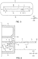
- FIG. 1 is a schematic view showing a card reader 1 in accordance with an embodiment of the present invention.
- FIG. 2 is a view showing a rear face of a card 2 shown in FIG. 1 .
- FIG. 3 is a view showing a card insertion member 8, light emitting elements 9, a light receiving element 10 and the like which are viewed from the "E-E" direction in FIG. 1 .
- FIG. 4 is an enlarged view showing the "F"-part in FIG. 1 .
- the card reader 1 in this embodiment is a device structured to perform reading of magnetic data recorded in a card 2 and/or recording of magnetic data to a card 2.
- the card reader 1 is, for example, mounted on a predetermined host apparatus such as an ATM and is used.
- a card 2 is a substantially rectangular card made of vinyl chloride whose thickness is about 0.7-0.8mm.
- a rear face of the card 2 is formed with a magnetic stripe 2a in which magnetic data are recorded.
- the magnetic stripe 2a is formed along a longitudinal direction of the card 2 which is formed in a substantially rectangular shape.
- the card 2 may be incorporated with an IC chip.
- the card 2 may be a PET (polyethylene terephthalate) card whose thickness is about 0.18-0.36mm, or may be a paper card having a predetermined thickness.
- the card reader 1 is formed with a card insertion port 3 into which a card 2 is inserted and from which the card 2 is ejected, and a card moving path 4 where the card 2 inserted into the card insertion port 3 is moved.
- the card reader 1 includes a magnetic head 5 which performs at least one of reading of magnetic data recorded in the card 2 and recording of magnetic data to the card 2, and drive rollers 6 and pad rollers 7 for conveying the card 2 in the card moving path 4.
- the card reader 1 includes a card insertion member (bezel) 8 formed with the card insertion port 3 and a light emitting element 9 and a light receiving element 10 for detecting a foreign matter which has been attached to the card insertion member 8.
- a card 2 having been inserted into the card insertion port 3 is moved in the "X" direction shown in FIG. 1 .
- the "X" direction is a moving direction of a card 2 and is an inserting and ejecting direction of the card 2 with respect to the card insertion port 3.
- a moving direction ("X" direction) of a card 2 is referred to as a front and rear direction.
- a thickness direction (“Z" direction in FIG. 1 and the like) of a card 2 having been inserted into the card insertion port 3 is referred to as an upper and lower direction
- a width direction (“Y" direction in FIG. 1 and the like) of a card 2 perpendicular to the front and rear direction and the upper and lower direction is referred to as a right and left direction.
- a side in the inserting direction of a card 2 to the card insertion port 3 (“X2" direction side in FIG. 1 and the like) is referred to as a rear side
- a side in the ejecting direction of a card 2 from the card insertion port 3 ("X1" direction side in FIG. 1 and the like) is referred to as a front side
- the "Z1" direction side in FIG. 1 and the like is referred to as an upper side
- the "Z2" direction side in FIG. 1 and the like which is the opposite side is referred to as a lower side.
- the lower side in this embodiment is a first direction side which is one side in a thickness direction of a card 2
- the upper side is a second direction side which is an opposite side to the first direction side.
- the card moving path 4 is connected with a rear end of the card insertion port 3.
- a card 2 is inserted into the card insertion port 3 and is moved in the card moving path 4 in a state that a rear face of the card 2 faces the lower side and, in addition, in a state that a longitudinal direction of the card 2 matches the front and rear direction.
- the magnetic head 5 is disposed so as to face the card moving path 4 from a lower side. In other words, the magnetic head 5 is disposed so as to contact with the card 2 from the lower side. Further, the magnetic head 5 is disposed at a position in the right and left direction where the magnetic stripe 2a is passed.
- the drive roller 6 and the pad roller 7 are disposed so as to face each other in the upper and lower direction.
- the drive roller 6 is connected with a drive mechanism (not shown) structured to drive the drive roller 6.
- the pad roller 7 is urged toward the drive roller 6.
- a light emitting element 9 emits infrared light.
- the light emitting element 9 in this embodiment is an infrared LED.
- a light receiving element 10 is capable of receiving infrared light.
- the light emitting element 9 and the light receiving element 10 are mounted on a common circuit board 11.
- the circuit board 11 is a rigid circuit board such as a glass epoxy circuit board or a flexible printed circuit board.
- two light emitting elements 9 and one light receiving element 10 are mounted on the circuit board 11.
- the two light emitting elements 9 are disposed so as to interpose the light receiving element 10 therebetween in the right and left direction.
- the light emitting elements 9, the light receiving element 10 and the circuit board 11 are disposed in an inside of the card insertion member 8. In FIG. 1 , the circuit board 11 is not shown.
- the card insertion member 8 structures a front end part of the card reader 1.
- the card insertion member 8 is formed of resin. Specifically, the card insertion member 8 is formed of black resin material which transmits infrared light but blocks visible light. A front face of the card insertion member 8 is formed in a flat face perpendicular to the front and rear direction.
- the card insertion member 8 is formed with the card insertion port 3 as described above. Further, the card insertion member 8 is formed with a front end part of the card moving path 4 and, as described above, a front end of the card moving path 4 is connected with a rear end of the card insertion port 3. The front end part of the card moving path 4 and the card insertion port 3 penetrate through the card insertion member 8 in the front and rear direction.
- a lower face and an upper face of the front end part of the card moving path 4 formed in the card insertion member 8 are formed to be flat faces perpendicular to the upper and lower direction.
- a shape of a rear end of the card insertion port 3 when viewed in the front and rear direction is a rectangular shape which is long and narrow in the right and left direction.
- the lower face of the card insertion port 3 is formed to be an inclined face 3a in a flat face shape which is inclined toward the lower side as going to the front side.
- the upper face of the card insertion port 3 is formed to be an inclined face 3b in a flat face shape which is inclined toward the upper side as going to the front side.
- both faces on the right and left sides of the card insertion port 3 are formed to be inclined faces 3c in a flat face shape which are inclined toward an outer side in the right and left direction as going to the front side.
- a lower side part 8a of the card insertion member 8 which is a portion on a lower side with respect to the card moving path 4 is formed in a hollow shape whose rear end side is opened.
- the light emitting elements 9, the light receiving element 10 and the circuit board 11 are disposed in an inside of the lower side part 8a. In other words, the light emitting elements 9, the light receiving element 10 and the circuit board 11 are disposed on a lower side with respect to the card moving path 4.
- the light emitting elements 9 and the light receiving element 10 are disposed at substantially the same position as the magnetic head 5 in the right and left direction when viewed in the front and rear direction.
- the magnetic head 5 in this embodiment is a two channel-type magnetic head having two head cores adjacent to each other in the right and left direction, and the light receiving element 10 is disposed at the same position as one channel of the magnetic head 5 in the right and left direction when viewed in the front and rear direction.
- the light receiving element 10 is disposed at the same position as the magnetic head 5 in the right and left direction when viewed in the front and rear direction.
- the light emitting element 9 emits light toward an obliquely upper front side.
- a light receiving face of the light receiving element 10 faces an obliquely upper front side.
- an optical axis of the light emitting element 9 is substantially coincided with an optical axis of the light receiving element 10.
- an inner side face of the lower side part 8a formed in a hollow shape is formed with an incidence surface 8b on which light emitted from the light emitting element 9 is incident.
- the incidence surface 8b is formed to be a flat face perpendicular to the optical axis of the light which is emitted from the light emitting element 9 and is incident on the incidence surface 8b.
- the incidence surface 8b is disposed on an obliquely lower rear side with respect to the inclined face 3a.
- An inclination angle ⁇ 1 of the incidence surface 8b with respect to the upper and lower direction is set to be smaller than an inclination angle ⁇ 2 of the inclined face 3a with respect to the upper and lower direction.
- the light emitted from the light emitting element 9 and transmitted through the incidence surface 8b is incident on the inclined face 3a.
- the light emitted from the light emitting element 9 is incident on the incidence surface 8b and is transmitted through the incidence surface 8b and, after passing a portion of the card insertion member 8 between the incidence surface 8b and the inclined face 3a, the light is incident on the inclined face 3a from the rear side and the lower side.
- the light emitted from the light emitting element 9 is incident on the inclined face 3a from the rear side and the lower side after passing a part of the card insertion member 8.
- the light transmitted through the incidence surface 8b and incident on the inclined face 3a is refracted at the inclined face 3a and is emitted from the inclined face 3a toward the front side.
- the light emitting element 9 in this embodiment emits, for example, infrared light having strong directivity. Therefore, the light emitted from the inclined face 3a linearly advances toward the front side.
- the light emitted from the inclined face 3a may be, for example, expanded to both sides in the upper and lower direction and both sides in the right and left direction.
- an optical axis "L1" of the light emitted from the inclined face 3a is inclined toward an upper side as going to the front side.
- an inclination angle ⁇ 3 with respect to the front and rear direction of the optical axis "L1" of the light emitted from the inclined face 3a is set to be smaller than an inclination angle ⁇ 4 of an optical axis "L2" of the light incident on the inclined face 3a with respect to the front and rear direction.
- the inclination angle ⁇ 3 is, for example, about 2°.
- Light emitted from the light emitting element 9 and reflected on a front side and an upper side of the inclined face 3a and light emitted from the light emitting element 9 and reflected on a front side of the card insertion member 8 are incident on the light receiving element 10.
- the light emitted from the inclined face 3a and reflected on the front side and the upper side of the inclined face 3a and the light emitted from the inclined face 3a and reflected on the front side of the card insertion member 8 are incident on the light receiving element 10.
- skimming magnetic head 20 in a case that a skimming magnetic head 20 is tried to be attached to a front side of the card insertion member 8, it is assumed that the skimming magnetic head 20 is disposed on a lower side with respect to the card moving path 4 and in a range of a predetermined distance "D" from a front end of the card insertion port 3 toward the front side (see FIG. 4 ). According to examination of the present inventors, it is assumed that the skimming magnetic head 20 is disposed on a lower side with respect to the card moving path 4 and in a range of 10 (cm) from the front end of the card insertion port 3 toward the front side.
- the optical axis "L1" of the light emitted from the inclined face 3a is, when viewed in the right and left direction, set to be a lower side with respect to a virtual line "VL" in a straight line shape, which is extended to the front side from the lower face of the card moving path 4, in a range of at least 10 (cm) from the front end of the card insertion port 3 toward the front side.
- the light emitted from the light emitting element 9 is incident on the inclined face 3a of the card insertion port 3 from a rear side and a lower side and is refracted at the inclined face 3a and emitted from the inclined face 3a toward a front side. Further, in this embodiment, the light emitted from the light emitting element 9 and reflected on a front side and an upper side of the inclined face 3a, and the light emitted from the light emitting element 9 and reflected on a front side of the card insertion member 8 are incident on the light receiving element 10.
- the skimming magnetic head 20 in both cases, that is, in a case that a skimming magnetic head 20 is attached on a front side of the card insertion member 8 and, in a case that a skimming magnetic head 20 is attached to the inclined face 3a of the card insertion port 3, the skimming magnetic head 20 can be detected by using the common light emitting element 9 and the common light receiving element 10. Accordingly, in this embodiment, the skimming magnetic head 20 attached on a front side of the card insertion member 8 and the skimming magnetic head 20 attached to the inclined face 3a of the card insertion port 3 can be detected with a simple structure.
- the optical axis "L1" of the light emitted from the inclined face 3a when viewed in the right and left direction, is inclined toward an upper side as going to the front side, and the inclination angle ⁇ 3 with respect to the front and rear direction of the optical axis "L1” is set to be smaller than the inclination angle ⁇ 4 with respect to the front and rear direction of the optical axis "L2" of the light incident on the inclined face 3a. Therefore, according to this embodiment, an irradiation range in the front and rear direction of the light emitted from the inclined face 3a is easily widened.
- a detection region in the front and rear direction for a skimming magnetic head 20 attached on a front side of the card insertion member 8 can be widened and, as a result, the skimming magnetic head 20 attached on a front side of the card insertion member 8 is easily detected.
- the optical axis "L1" of the light emitted from the inclined face 3a is located on a lower side with respect to the virtual line "VL" in a range of at least 10cm from the front end of the card insertion port 3 toward the front side and thus, the light emitted from the inclined face 3a can be irradiated to an assumed attaching range of the skimming magnetic head 20 which is attached on a front side of the card insertion member 8. Therefore, according to this embodiment, the skimming magnetic head 20 attached on a front side of the card insertion member 8 is further easily detected.
- the card insertion member 8 transmits infrared light but blocks visible light. Therefore, according to this embodiment, visible light can be prevented from being incident on the light receiving element 10 from the outside of the card insertion member 8 and, as a result, erroneous detection of the light receiving element 10 can be prevented. Accordingly, in this embodiment, the skimming magnetic head 20 attached on a front side of the card insertion member 8 and the skimming magnetic head 20 attached to the inclined face 3a of the card insertion port 3 can be detected with a high degree of accuracy.
- the skimming magnetic head 20 is commonly disposed at the same position as the magnetic head 5 in the right and left direction.
- the light receiving element 10 when viewed in the front and rear direction, is disposed at the same position as the magnetic head 5 in the right and left direction and thus, the skimming magnetic head 20 attached on a front side of the card insertion member 8 and the skimming magnetic head 20 attached to the inclined face 3a of the card insertion port 3 are easily detected.
- an inner side face of a lower side part 8a which is formed in a hollow shape may be formed with an incidence surface 8c on which light emitted from a light emitting element 9 is incident and a reflection surface 8d which reflects the light toward the inclined face 3a.
- the light emitted from the light emitting element 9 and transmitted through the incidence surface 8c is reflected by the reflection surface 8d and then incident on the inclined face 3a.
- a shape of the card insertion member 8 can be simplified.
- the light emitting element 9 emits light toward directly above and a light receiving face of a light receiving element 10 faces directly above.
- the incidence surface 8c is, for example, a flat face perpendicular to the upper and lower direction and is perpendicular to the optical axis of the light which is emitted from the light emitting element 9 and incident on the incidence surface 8c.
- an angle of the reflection surface 8d is set to be an angle so that the light incident on the reflection surface 8d is totally reflected.
- the same reference signs are used in the structures similar to the embodiment described above.
- a magnetic stripe may be formed on a front face of a card 2.
- the card reader 1 includes a magnetic head structured to contact with a card 2 from an upper side instead of the magnetic head 5, alternatively, in addition to the magnetic head 5.
- an upper side part of the card insertion member 8 which is an upper side portion with respect to the card moving path 4 is formed in a hollow shape, and the light emitting element 9, the light receiving element 10 and the circuit board 11 are disposed in an inside of the upper side part.
- an inner side face of the upper side part formed in a hollow shape is formed with an incidence surface on which light emitted from the light emitting element 9 is incident, and the light emitted from the light emitting element 9 and transmitted through the incidence surface is incident on the inclined face 3b from a rear side and an upper side. Further, the light incident on the inclined face 3b is refracted at the inclined face 3b and is emitted from the inclined face 3b toward the front side. When viewed in the right and left direction, an optical axis of the light emitted from the inclined face 3b is inclined toward a lower side as going to the front side.
- the light receiving element 10 is made incident with the light emitted from the light emitting element 9 and reflected on a front side and a lower side of the inclined face 3b and the light emitted from the light emitting element 9 and reflected on a front side of the card insertion member 8.
- a magnetic stripe is formed on a front face of a card 2 instead of the magnetic stripe 2a
- the light emitting element 9, the light receiving element 10 and the circuit board 11 are not disposed in an inside of the lower side part 8a.
- an upper side (“Z1" direction side) is the first direction side
- a lower side (“Z2" direction side) is the second direction side.
- the optical axis "L1" of the light emitted from the inclined face 3a may be parallel to the front and rear direction, or may be inclined toward the lower side as going to the front side. Further, in the embodiment described above, the optical axis "L1" of the light emitted from the inclined face 3a may be disposed on an upper side with respect to the virtual line "VL" in a range of 10 (cm) from the front end of the card insertion port 3 toward the front side. In addition, in the embodiment described above, the inclined face 3a may be formed in a protruding curved face shape.
- the light emitting element 9, the light receiving element 10 and the circuit board 11 may be disposed on an outer side of the card insertion member 8. Specifically, the light emitting element 9, the light receiving element 10 and the circuit board 11 may be disposed on a rear side with respect to the rear end of the card insertion member 8.
- the card reader 1 is a card conveyance type card reader having the drive roller 6 and the pad roller 7.
- the card reader 1 may be a manual type card reader in which an operation is manually performed by a user.
Landscapes
- Engineering & Computer Science (AREA)
- Physics & Mathematics (AREA)
- General Physics & Mathematics (AREA)
- Theoretical Computer Science (AREA)
- Artificial Intelligence (AREA)
- Computer Vision & Pattern Recognition (AREA)
- Business, Economics & Management (AREA)
- Accounting & Taxation (AREA)
- Finance (AREA)
- Conveying Record Carriers (AREA)
- Recording Or Reproducing By Magnetic Means (AREA)
Abstract
Description
- The present invention relates to a card reader structured to perform reading of magnetic data recorded in a card and/or recording of magnetic data to a card.
- Conventionally, a card reader has been known which is capable of preventing so-called skimming, that is, a criminal attaches a magnetic head to a card insertion part of a card reader and illegally acquires magnetic data of a card (for example, see Patent Literature 1). A card reader described in
Patent Literature 1 includes a photo reflector for detecting that a magnetic head for skimming (hereinafter, referred to as a "skimming magnetic head") has been attached on a front side of a card insertion part (front panel). In the card reader, when attachment of a skimming magnetic head on a front side of the card insertion part is detected by a photo reflector, a predetermined processing is executed and thereby skimming is capable of being prevented. - In the card reader described in
Patent Literature 1, a magnetic head is disposed so as to contact with an under face of a card which is inserted into the card reader. Further, in the card reader, in order to easily insert a card into a card insertion port, a lower face of the card insertion port is formed to be an inclined face in a flat face shape which is inclined to a lower side as going toward a front side, and an upper face of the card insertion port is formed to be an inclined face in a flat face shape which is inclined toward an upper side as going to the front side. - [PTL 1] Japanese Patent Laid-Open No.
2007-265189 - Skimming by a criminal has been crafted year by year, and a situation has occurred that a small skimming magnetic head is attached to the lower face (inclined face) of the card insertion port where a skimming magnetic head has not been conventionally attached. In the card reader described in
Patent Literature 1, a skimming magnetic head attached on the front side of the card insertion part can be detected by a photo reflector. However, in the card reader described inPatent Literature 1, a situation that a skimming magnetic head is attached to the inclined face of the card insertion port is not anticipated and it is difficult to detect a skimming magnetic head attached to the inclined face of the card insertion port. - In view of the problem described above, the present invention provides a card reader which is capable of detecting a skimming magnetic head attached on a front side of a card insertion member formed with a card insertion port and a skimming magnetic head attached to an inclined face of the card insertion port with a simple structure.
- To solve the above-mentioned problem, the present invention provides a card reader including a magnetic head which performs at least one of reading of magnetic data recorded in a card and recording of magnetic data to the card, a card insertion member which is formed with a card insertion port into which the card is inserted, and a light emitting element and a light receiving element structured to detect that a foreign matter has been attached to the card insertion member. When a side in an inserting direction of the card to the card insertion port is defined as a rear side, a side in an ejecting direction of the card from the card insertion port is defined as a front side, one side in a thickness direction of the card inserted into the card insertion port is defined as a first direction side, an opposite side to the first direction side is defined as a second direction side, and an inserting and ejecting direction of the card into and from the card insertion port is defined as a front and rear direction, the magnetic head is disposed so as to contact with the card from the first direction side, a face on the first direction side of the card insertion port is formed to be an inclined face in a protruding curved face shape or in a flat face shape which is inclined toward the first direction side as going to the front side, and light emitted from the light emitting element is passed through a part of the card insertion member and then, the light is incident on the inclined face from the rear side and the first direction side and is refracted at the inclined face and is emitted from the inclined face toward at least the front side, and light emitted from the light emitting element and reflected on the front side and the second direction side of the inclined face, and light emitted from the light emitting element and reflected on the front side of the card insertion member are incident on the light receiving element.
- The card reader in the present invention includes a light emitting element and a light receiving element structured to detect that a foreign matter has been attached to the card insertion member, and light emitted from the light emitting element is incident on the inclined face, which is a face on the first direction side of the card insertion port, from the rear side and the first direction side and is refracted at the inclined face and is emitted from the inclined face toward at least the front side. Further, in the present invention, light emitted from the light emitting element and reflected on the front side and the second direction side of the inclined face, and light emitted from the light emitting element and reflected on the front side of the card insertion member are incident on the light receiving element.
- Therefore, according to the present invention, in both of a case that a skimming magnetic head has been attached on a front side of the card insertion member, and a case that a skimming magnetic head has been attached to the inclined face of the card insertion port, the skimming magnetic head can be detected by using a common light emitting element and a common light receiving element. Accordingly, in the present invention, a skimming magnetic head attached on a front side of the card insertion member and a skimming magnetic head attached to the inclined face of the card insertion port can be detected with a simple structure.
- In the present invention, it is preferable that, in a case that a direction perpendicular to the front and rear direction and the thickness direction of the card is defined as a width direction of the card, when viewed in the width direction of the card, an optical axis of light emitted from the inclined face is inclined toward the second direction side as going to the front side, and an inclination angle of an optical axis of the light emitted from the inclined face with respect to the front and rear direction is smaller than an inclination angle with respect to the front and rear direction of an optical axis of light which is incident on the inclined face. According to this structure, an irradiation range in the front and rear direction of the light emitted from the inclined face is easily widened. Therefore, a detection region in the front and rear direction of a skimming magnetic head attached on the front side of the card insertion member can be widened and, as a result, the skimming magnetic head attached on the front side of the card insertion member is easily detected.
- In the present invention, it is preferable that the card reader is formed with a card moving path which is connected with a rear end of the card insertion port and in which the card inserted into the card insertion port is moved and, when viewed in the width direction of the card, the optical axis of the light emitted from the inclined face is located on the first direction side with respect to a virtual line in a straight line shape which is extended to the front side from a face on the first direction side of the card moving path in a range of at least 10cm from a front end of the card insertion port toward the front side. According to examination of the present inventors, when structured as described above, light emitted from the inclined face can be irradiated to an assumed attaching range of a skimming magnetic head (range in which a skimming magnetic head is assumed to be attached) which is attached on a front side of the card insertion member. Therefore, a skimming magnetic head having been attached on a front side of the card insertion member is further easily detected.
- In the present invention, the light emitting element and the light receiving element are disposed on the first direction side with respect to the card moving path. Further, in the present invention, the inclined face is, for example, formed in a flat face shape.
- In the present invention, it is preferable that the light emitting element emits infrared light, and the card insertion member transmits the infrared light and blocks visible light. According to this structure, visible light can be prevented from being incident on the light receiving element from the outside of the card insertion member and thus, erroneous detection of the light receiving element can be prevented. Therefore, a skimming magnetic head attached on a front side of the card insertion member and a skimming magnetic head attached to the inclined face of the card insertion port can be detected with a high degree of accuracy.
- In the present invention, it is preferable that, when viewed in the front and rear direction, the light receiving element is disposed at the same position as the magnetic head in the width direction of the card. A skimming magnetic head is commonly disposed at the same position as the magnetic head in a width direction of a card and thus, according to this structure, the skimming magnetic head is easily detected.
- In the present invention, it is preferable that the card insertion member is formed with an incidence surface on which the light emitted from the light emitting element is incident, and the light emitted from the light emitting element and transmitted through the incidence surface is incident on the inclined face. According to this structure, a shape of the card insertion member can be simplified. Further, in the present invention, it may be structured that the card insertion member is formed with an incidence surface on which the light emitted from the light emitting element is incident and a reflection surface reflecting the light toward the inclined face, and the light emitted from the light emitting element and transmitted through the incidence surface is reflected by the reflection surface and then is incident on the inclined face.
- As described above, according to the card reader in the present invention, a skimming magnetic head attached on the front side of the card insertion member which is formed with the card insertion port, and a skimming magnetic head attached to the inclined face of the card insertion port can be detected with a simple structure.
-
- [
FIG. 1 ]
FIG. 1 is a schematic view showing a card reader in accordance with an embodiment of the present invention. - [
FIG. 2 ]
FIG. 2 is a view showing a rear face of a card shown inFIG. 1 . - [
FIG. 3 ]
FIG. 3 is a view showing a card insertion member, light emitting elements, a light receiving element and the like which are viewed from the "E-E" direction inFIG. 1 . - [
FIG. 4 ]
FIG. 4 is an enlarged view showing the "F"-part inFIG. 1 . - [
FIG. 5 ]
FIG. 5 is a view for explaining a structure of a card insertion member and an arrangement of a light emitting element in accordance with another embodiment of the present invention. - An embodiment of the present invention will be described below with reference to the accompanying drawings.
-
FIG. 1 is a schematic view showing acard reader 1 in accordance with an embodiment of the present invention.FIG. 2 is a view showing a rear face of acard 2 shown inFIG. 1 .FIG. 3 is a view showing acard insertion member 8,light emitting elements 9, alight receiving element 10 and the like which are viewed from the "E-E" direction inFIG. 1 .FIG. 4 is an enlarged view showing the "F"-part inFIG. 1 . - The
card reader 1 in this embodiment is a device structured to perform reading of magnetic data recorded in acard 2 and/or recording of magnetic data to acard 2. Thecard reader 1 is, for example, mounted on a predetermined host apparatus such as an ATM and is used. - A
card 2 is a substantially rectangular card made of vinyl chloride whose thickness is about 0.7-0.8mm. A rear face of thecard 2 is formed with amagnetic stripe 2a in which magnetic data are recorded. Themagnetic stripe 2a is formed along a longitudinal direction of thecard 2 which is formed in a substantially rectangular shape. Thecard 2 may be incorporated with an IC chip. Further, thecard 2 may be a PET (polyethylene terephthalate) card whose thickness is about 0.18-0.36mm, or may be a paper card having a predetermined thickness. - The
card reader 1 is formed with acard insertion port 3 into which acard 2 is inserted and from which thecard 2 is ejected, and acard moving path 4 where thecard 2 inserted into thecard insertion port 3 is moved. Thecard reader 1 includes amagnetic head 5 which performs at least one of reading of magnetic data recorded in thecard 2 and recording of magnetic data to thecard 2, and driverollers 6 andpad rollers 7 for conveying thecard 2 in thecard moving path 4. Further, thecard reader 1 includes a card insertion member (bezel) 8 formed with thecard insertion port 3 and alight emitting element 9 and alight receiving element 10 for detecting a foreign matter which has been attached to thecard insertion member 8. - In this embodiment, a
card 2 having been inserted into thecard insertion port 3 is moved in the "X" direction shown inFIG. 1 . In other words, the "X" direction is a moving direction of acard 2 and is an inserting and ejecting direction of thecard 2 with respect to thecard insertion port 3. In the following descriptions, a moving direction ("X" direction) of acard 2 is referred to as a front and rear direction. Further, a thickness direction ("Z" direction inFIG. 1 and the like) of acard 2 having been inserted into thecard insertion port 3 is referred to as an upper and lower direction, and a width direction ("Y" direction inFIG. 1 and the like) of acard 2 perpendicular to the front and rear direction and the upper and lower direction is referred to as a right and left direction. - Further, in the following descriptions, in the front and rear direction, a side in the inserting direction of a
card 2 to the card insertion port 3 ("X2" direction side inFIG. 1 and the like) is referred to as a rear side, a side in the ejecting direction of acard 2 from the card insertion port 3 ("X1" direction side inFIG. 1 and the like) is referred to as a front side and, in the upper and lower direction, the "Z1" direction side inFIG. 1 and the like is referred to as an upper side, and the "Z2" direction side inFIG. 1 and the like which is the opposite side is referred to as a lower side. The lower side in this embodiment is a first direction side which is one side in a thickness direction of acard 2, and the upper side is a second direction side which is an opposite side to the first direction side. - The
card moving path 4 is connected with a rear end of thecard insertion port 3. Acard 2 is inserted into thecard insertion port 3 and is moved in thecard moving path 4 in a state that a rear face of thecard 2 faces the lower side and, in addition, in a state that a longitudinal direction of thecard 2 matches the front and rear direction. Themagnetic head 5 is disposed so as to face thecard moving path 4 from a lower side. In other words, themagnetic head 5 is disposed so as to contact with thecard 2 from the lower side. Further, themagnetic head 5 is disposed at a position in the right and left direction where themagnetic stripe 2a is passed. Thedrive roller 6 and thepad roller 7 are disposed so as to face each other in the upper and lower direction. Thedrive roller 6 is connected with a drive mechanism (not shown) structured to drive thedrive roller 6. Thepad roller 7 is urged toward thedrive roller 6. - A
light emitting element 9 emits infrared light. Thelight emitting element 9 in this embodiment is an infrared LED. Alight receiving element 10 is capable of receiving infrared light. Thelight emitting element 9 and thelight receiving element 10 are mounted on acommon circuit board 11. Thecircuit board 11 is a rigid circuit board such as a glass epoxy circuit board or a flexible printed circuit board. In this embodiment, twolight emitting elements 9 and onelight receiving element 10 are mounted on thecircuit board 11. The twolight emitting elements 9 are disposed so as to interpose thelight receiving element 10 therebetween in the right and left direction. Thelight emitting elements 9, thelight receiving element 10 and thecircuit board 11 are disposed in an inside of thecard insertion member 8. InFIG. 1 , thecircuit board 11 is not shown. - The
card insertion member 8 structures a front end part of thecard reader 1. Thecard insertion member 8 is formed of resin. Specifically, thecard insertion member 8 is formed of black resin material which transmits infrared light but blocks visible light. A front face of thecard insertion member 8 is formed in a flat face perpendicular to the front and rear direction. Thecard insertion member 8 is formed with thecard insertion port 3 as described above. Further, thecard insertion member 8 is formed with a front end part of thecard moving path 4 and, as described above, a front end of thecard moving path 4 is connected with a rear end of thecard insertion port 3. The front end part of thecard moving path 4 and thecard insertion port 3 penetrate through thecard insertion member 8 in the front and rear direction. - A lower face and an upper face of the front end part of the
card moving path 4 formed in thecard insertion member 8 are formed to be flat faces perpendicular to the upper and lower direction. A shape of a rear end of thecard insertion port 3 when viewed in the front and rear direction is a rectangular shape which is long and narrow in the right and left direction. The lower face of thecard insertion port 3 is formed to be aninclined face 3a in a flat face shape which is inclined toward the lower side as going to the front side. The upper face of thecard insertion port 3 is formed to be aninclined face 3b in a flat face shape which is inclined toward the upper side as going to the front side. Further, both faces on the right and left sides of thecard insertion port 3 are formed to be inclined faces 3c in a flat face shape which are inclined toward an outer side in the right and left direction as going to the front side. - A
lower side part 8a of thecard insertion member 8 which is a portion on a lower side with respect to thecard moving path 4 is formed in a hollow shape whose rear end side is opened. Thelight emitting elements 9, thelight receiving element 10 and thecircuit board 11 are disposed in an inside of thelower side part 8a. In other words, thelight emitting elements 9, thelight receiving element 10 and thecircuit board 11 are disposed on a lower side with respect to thecard moving path 4. Thelight emitting elements 9 and thelight receiving element 10 are disposed at substantially the same position as themagnetic head 5 in the right and left direction when viewed in the front and rear direction. Further, themagnetic head 5 in this embodiment is a two channel-type magnetic head having two head cores adjacent to each other in the right and left direction, and thelight receiving element 10 is disposed at the same position as one channel of themagnetic head 5 in the right and left direction when viewed in the front and rear direction. In other words, thelight receiving element 10 is disposed at the same position as themagnetic head 5 in the right and left direction when viewed in the front and rear direction. - The
light emitting element 9 emits light toward an obliquely upper front side. A light receiving face of thelight receiving element 10 faces an obliquely upper front side. In this embodiment, when viewed in the right and left direction, an optical axis of thelight emitting element 9 is substantially coincided with an optical axis of thelight receiving element 10. As shown inFIG. 4 , an inner side face of thelower side part 8a formed in a hollow shape is formed with anincidence surface 8b on which light emitted from thelight emitting element 9 is incident. Theincidence surface 8b is formed to be a flat face perpendicular to the optical axis of the light which is emitted from thelight emitting element 9 and is incident on theincidence surface 8b. Further, theincidence surface 8b is disposed on an obliquely lower rear side with respect to theinclined face 3a. An inclination angle θ1 of theincidence surface 8b with respect to the upper and lower direction is set to be smaller than an inclination angle θ2 of theinclined face 3a with respect to the upper and lower direction. - In this embodiment, as shown in
FIG. 4 , the light emitted from thelight emitting element 9 and transmitted through theincidence surface 8b is incident on theinclined face 3a. Specifically, the light emitted from thelight emitting element 9 is incident on theincidence surface 8b and is transmitted through theincidence surface 8b and, after passing a portion of thecard insertion member 8 between theincidence surface 8b and theinclined face 3a, the light is incident on theinclined face 3a from the rear side and the lower side. In other words, the light emitted from thelight emitting element 9 is incident on theinclined face 3a from the rear side and the lower side after passing a part of thecard insertion member 8. - Further, the light transmitted through the
incidence surface 8b and incident on theinclined face 3a is refracted at theinclined face 3a and is emitted from theinclined face 3a toward the front side. Thelight emitting element 9 in this embodiment emits, for example, infrared light having strong directivity. Therefore, the light emitted from theinclined face 3a linearly advances toward the front side. In this case, the light emitted from theinclined face 3a may be, for example, expanded to both sides in the upper and lower direction and both sides in the right and left direction. - As shown in
FIG. 4 , when viewed in the right and left direction, an optical axis "L1" of the light emitted from theinclined face 3a is inclined toward an upper side as going to the front side. Further, when viewed in the right and left direction, an inclination angle θ3 with respect to the front and rear direction of the optical axis "L1" of the light emitted from theinclined face 3a is set to be smaller than an inclination angle θ4 of an optical axis "L2" of the light incident on theinclined face 3a with respect to the front and rear direction. The inclination angle θ3 is, for example, about 2°. - Light emitted from the
light emitting element 9 and reflected on a front side and an upper side of theinclined face 3a and light emitted from thelight emitting element 9 and reflected on a front side of thecard insertion member 8 are incident on thelight receiving element 10. Specifically, the light emitted from theinclined face 3a and reflected on the front side and the upper side of theinclined face 3a and the light emitted from theinclined face 3a and reflected on the front side of thecard insertion member 8 are incident on thelight receiving element 10. - In this embodiment, in a case that a skimming
magnetic head 20 is tried to be attached to a front side of thecard insertion member 8, it is assumed that the skimmingmagnetic head 20 is disposed on a lower side with respect to thecard moving path 4 and in a range of a predetermined distance "D" from a front end of thecard insertion port 3 toward the front side (seeFIG. 4 ). According to examination of the present inventors, it is assumed that the skimmingmagnetic head 20 is disposed on a lower side with respect to thecard moving path 4 and in a range of 10 (cm) from the front end of thecard insertion port 3 toward the front side. Therefore, in this embodiment, the optical axis "L1" of the light emitted from theinclined face 3a is, when viewed in the right and left direction, set to be a lower side with respect to a virtual line "VL" in a straight line shape, which is extended to the front side from the lower face of thecard moving path 4, in a range of at least 10 (cm) from the front end of thecard insertion port 3 toward the front side. - As described above, in this embodiment, the light emitted from the
light emitting element 9 is incident on theinclined face 3a of thecard insertion port 3 from a rear side and a lower side and is refracted at theinclined face 3a and emitted from theinclined face 3a toward a front side. Further, in this embodiment, the light emitted from thelight emitting element 9 and reflected on a front side and an upper side of theinclined face 3a, and the light emitted from thelight emitting element 9 and reflected on a front side of thecard insertion member 8 are incident on thelight receiving element 10. - Therefore, in this embodiment, in both cases, that is, in a case that a skimming
magnetic head 20 is attached on a front side of thecard insertion member 8 and, in a case that a skimmingmagnetic head 20 is attached to theinclined face 3a of thecard insertion port 3, the skimmingmagnetic head 20 can be detected by using the commonlight emitting element 9 and the commonlight receiving element 10. Accordingly, in this embodiment, the skimmingmagnetic head 20 attached on a front side of thecard insertion member 8 and the skimmingmagnetic head 20 attached to theinclined face 3a of thecard insertion port 3 can be detected with a simple structure. - In this embodiment, when viewed in the right and left direction, the optical axis "L1" of the light emitted from the
inclined face 3a is inclined toward an upper side as going to the front side, and the inclination angle θ3 with respect to the front and rear direction of the optical axis "L1" is set to be smaller than the inclination angle θ4 with respect to the front and rear direction of the optical axis "L2" of the light incident on theinclined face 3a. Therefore, according to this embodiment, an irradiation range in the front and rear direction of the light emitted from theinclined face 3a is easily widened. Accordingly, in this embodiment, a detection region in the front and rear direction for a skimmingmagnetic head 20 attached on a front side of thecard insertion member 8 can be widened and, as a result, the skimmingmagnetic head 20 attached on a front side of thecard insertion member 8 is easily detected. - Especially, in this embodiment, when viewed in the right and left direction, the optical axis "L1" of the light emitted from the
inclined face 3a is located on a lower side with respect to the virtual line "VL" in a range of at least 10cm from the front end of thecard insertion port 3 toward the front side and thus, the light emitted from theinclined face 3a can be irradiated to an assumed attaching range of the skimmingmagnetic head 20 which is attached on a front side of thecard insertion member 8. Therefore, according to this embodiment, the skimmingmagnetic head 20 attached on a front side of thecard insertion member 8 is further easily detected. - In this embodiment, the
card insertion member 8 transmits infrared light but blocks visible light. Therefore, according to this embodiment, visible light can be prevented from being incident on thelight receiving element 10 from the outside of thecard insertion member 8 and, as a result, erroneous detection of thelight receiving element 10 can be prevented. Accordingly, in this embodiment, the skimmingmagnetic head 20 attached on a front side of thecard insertion member 8 and the skimmingmagnetic head 20 attached to theinclined face 3a of thecard insertion port 3 can be detected with a high degree of accuracy. - Further, the skimming
magnetic head 20 is commonly disposed at the same position as themagnetic head 5 in the right and left direction. In this embodiment, when viewed in the front and rear direction, thelight receiving element 10 is disposed at the same position as themagnetic head 5 in the right and left direction and thus, the skimmingmagnetic head 20 attached on a front side of thecard insertion member 8 and the skimmingmagnetic head 20 attached to theinclined face 3a of thecard insertion port 3 are easily detected. - Although the present invention has been shown and described with reference to a specific embodiment, various changes and modifications will be apparent to those skilled in the art from the teachings herein.
- In the embodiment described above, as shown in
FIG. 5 , an inner side face of alower side part 8a which is formed in a hollow shape may be formed with anincidence surface 8c on which light emitted from alight emitting element 9 is incident and areflection surface 8d which reflects the light toward theinclined face 3a. In this case, the light emitted from thelight emitting element 9 and transmitted through theincidence surface 8c is reflected by thereflection surface 8d and then incident on theinclined face 3a. In comparison with the modified embodiment shown inFIG. 5 , in the embodiment described above, a shape of thecard insertion member 8 can be simplified. - In the modified embodiment shown in
FIG. 5 , for example, thelight emitting element 9 emits light toward directly above and a light receiving face of alight receiving element 10 faces directly above. Further, theincidence surface 8c is, for example, a flat face perpendicular to the upper and lower direction and is perpendicular to the optical axis of the light which is emitted from thelight emitting element 9 and incident on theincidence surface 8c. Further, an angle of thereflection surface 8d is set to be an angle so that the light incident on thereflection surface 8d is totally reflected. InFIG. 5 , the same reference signs are used in the structures similar to the embodiment described above. - In the embodiment described above, instead of the
magnetic stripe 2a formed on a rear face of acard 2, alternatively, in addition to themagnetic stripe 2a, a magnetic stripe may be formed on a front face of acard 2. In this case, thecard reader 1 includes a magnetic head structured to contact with acard 2 from an upper side instead of themagnetic head 5, alternatively, in addition to themagnetic head 5. Further, in this case, an upper side part of thecard insertion member 8 which is an upper side portion with respect to thecard moving path 4 is formed in a hollow shape, and thelight emitting element 9, thelight receiving element 10 and thecircuit board 11 are disposed in an inside of the upper side part. - Further, in this case, for example, an inner side face of the upper side part formed in a hollow shape is formed with an incidence surface on which light emitted from the
light emitting element 9 is incident, and the light emitted from thelight emitting element 9 and transmitted through the incidence surface is incident on theinclined face 3b from a rear side and an upper side. Further, the light incident on theinclined face 3b is refracted at theinclined face 3b and is emitted from theinclined face 3b toward the front side. When viewed in the right and left direction, an optical axis of the light emitted from theinclined face 3b is inclined toward a lower side as going to the front side. Thelight receiving element 10 is made incident with the light emitted from thelight emitting element 9 and reflected on a front side and a lower side of theinclined face 3b and the light emitted from thelight emitting element 9 and reflected on a front side of thecard insertion member 8. - In a case that a magnetic stripe is formed on a front face of a
card 2 instead of themagnetic stripe 2a, thelight emitting element 9, thelight receiving element 10 and thecircuit board 11 are not disposed in an inside of thelower side part 8a. Further, in a case that a magnetic stripe is formed on a front face of acard 2 instead of themagnetic stripe 2a, an upper side ("Z1" direction side) is the first direction side, and a lower side ("Z2" direction side) is the second direction side. - In the embodiment described above, the optical axis "L1" of the light emitted from the
inclined face 3a may be parallel to the front and rear direction, or may be inclined toward the lower side as going to the front side. Further, in the embodiment described above, the optical axis "L1" of the light emitted from theinclined face 3a may be disposed on an upper side with respect to the virtual line "VL" in a range of 10 (cm) from the front end of thecard insertion port 3 toward the front side. In addition, in the embodiment described above, theinclined face 3a may be formed in a protruding curved face shape. Further, in the embodiment described above, thelight emitting element 9, thelight receiving element 10 and thecircuit board 11 may be disposed on an outer side of thecard insertion member 8. Specifically, thelight emitting element 9, thelight receiving element 10 and thecircuit board 11 may be disposed on a rear side with respect to the rear end of thecard insertion member 8. - In the embodiment described above, only one
light emitting element 9 may be mounted on thecircuit board 11. However, in a case that two light emittingelements 9 are mounted on thecircuit board 11, an irradiation range of light of thelight emitting element 9 can be widened and thus, a detection region for the skimmingmagnetic head 20 can be widened. Further, in the embodiment described above, thecard reader 1 is a card conveyance type card reader having thedrive roller 6 and thepad roller 7. However, thecard reader 1 may be a manual type card reader in which an operation is manually performed by a user. -
- 1
- card reader
- 2
- card
- 3
- card insertion port
- 3a
- inclined face
- 4
- card moving path
- 5
- magnetic head
- 8
- card insertion member
- 8b, 8c
- incidence surface
- 8d
- reflection surface
- 9
- light emitting element
- 10
- light receiving element
- "L1"
- optical axis of light emitted from inclined face
- "L2"
- optical axis of light incident on inclined face
- "VL"
- virtual line
- "X"
- front and rear direction (inserting and ejecting direction of card)
- "X1"
- front side (side in ejecting direction of card)
- "X2"
- rear side (side in inserting direction of card)
- "Y"
- width direction of card
- "Z"
- thickness direction of card
- "Z1"
- second direction side
- "Z2"
- first direction side
- θ3
- inclination angle of optical axis of light emitted from inclined face
- θ4
- inclination angle of optical axis of light incident on inclined face
Claims (9)
- A card reader comprising:a magnetic head which performs at least one of reading of magnetic data recorded in a card and recording of magnetic data to the card;a card insertion member which is formed with a card insertion port into which the card is inserted; anda light emitting element and a light receiving element structured to detect that a foreign matter has been attached to the card insertion member;wherein when a side in an inserting direction of the card to the card insertion port is defined as a rear side, a side in an ejecting direction of the card from the card insertion port is defined as a front side, one side in a thickness direction of the card inserted into the card insertion port is defined as a first direction side, an opposite side to the first direction side is defined as a second direction side, and an inserting and ejecting direction of the card into and from the card insertion port is defined as a front and rear direction,the magnetic head is disposed so as to contact with the card from the first direction side;a face on the first direction side of the card insertion port is formed to be an inclined face in a protruding curved face shape or in a flat face shape which is inclined toward the first direction side as going to the front side;light emitted from the light emitting element is passed through a part of the card insertion member and then, the light is incident on the inclined face from the rear side and the first direction side and is refracted at the inclined face and is emitted from the inclined face toward at least the front side; andlight emitted from the light emitting element and reflected on the front side and the second direction side of the inclined face, and light emitted from the light emitting element and reflected on the front side of the card insertion member are incident on the light receiving element.
- The card reader according to claim 1, wherein
in a case that a direction perpendicular to the front and rear direction and the thickness direction of the card is defined as a width direction of the card,
when viewed in the width direction of the card, an optical axis of light emitted from the inclined face is inclined toward the second direction side as going to the front side, and
an inclination angle of an optical axis of the light emitted from the inclined face with respect to the front and rear direction is smaller than an inclination angle with respect to the front and rear direction of an optical axis of light which is incident on the inclined face. - The card reader according to claim 2, further comprising a card moving path which is connected with a rear end of the card insertion port and in which the card inserted into the card insertion port is moved,
wherein when viewed in the width direction of the card, the optical axis of the light emitted from the inclined face is located on the first direction side with respect to a virtual line in a straight line shape which is extended to the front side from a face on the first direction side of the card moving path in a range of at least 10cm from a front end of the card insertion port toward the front side. - The card reader according to one of claims 1 through 3, wherein the light emitting element and the light receiving element are disposed on the first direction side with respect to the card moving path.
- The card reader according to one of claims 1 through 4, wherein the inclined face is formed in a flat face shape.
- The card reader according to one of claims 1 through 5, wherein the light emitting element emits infrared light, and the card insertion member transmits the infrared light and blocks visible light.
- The card reader according to one of claims 1 through 6, wherein when viewed in the front and rear direction, the light receiving element is disposed at a same position as the magnetic head in the width direction of the card.
- The card reader according to one of claims 1 through 7, wherein
the card insertion member is formed with an incidence surface on which the light emitted from the light emitting element is incident, and
the light emitted from the light emitting element and transmitted through the incidence surface is incident on the inclined face. - The card reader according to one of claims 1 through 7, wherein
the card insertion member is formed with an incidence surface on which the light emitted from the light emitting element is incident and a reflection surface reflecting the light toward the inclined face, and
the light emitted from the light emitting element and transmitted through the incidence surface is reflected by the reflection surface and then is incident on the inclined face.
Applications Claiming Priority (2)
| Application Number | Priority Date | Filing Date | Title |
|---|---|---|---|
| JP2017166586A JP7085814B2 (en) | 2017-08-31 | 2017-08-31 | Card reader |
| PCT/JP2018/029083 WO2019044370A1 (en) | 2017-08-31 | 2018-08-02 | Card reader |
Publications (3)
| Publication Number | Publication Date |
|---|---|
| EP3678137A1 true EP3678137A1 (en) | 2020-07-08 |
| EP3678137A4 EP3678137A4 (en) | 2021-05-19 |
| EP3678137B1 EP3678137B1 (en) | 2023-09-27 |
Family
ID=65527635
Family Applications (1)
| Application Number | Title | Priority Date | Filing Date |
|---|---|---|---|
| EP18849954.5A Active EP3678137B1 (en) | 2017-08-31 | 2018-08-02 | Card reader |
Country Status (5)
| Country | Link |
|---|---|
| US (1) | US11055500B2 (en) |
| EP (1) | EP3678137B1 (en) |
| JP (1) | JP7085814B2 (en) |
| CN (1) | CN111052233B (en) |
| WO (1) | WO2019044370A1 (en) |
Families Citing this family (2)
| Publication number | Priority date | Publication date | Assignee | Title |
|---|---|---|---|---|
| JP7479964B2 (en) | 2020-06-30 | 2024-05-09 | ニデックインスツルメンツ株式会社 | Card slot and card reader |
| JP2022186325A (en) * | 2021-06-04 | 2022-12-15 | 日立チャネルソリューションズ株式会社 | Card reader and foreign object detection method for card reader |
Family Cites Families (13)
| Publication number | Priority date | Publication date | Assignee | Title |
|---|---|---|---|---|
| US7500609B2 (en) * | 1999-07-09 | 2009-03-10 | Nidec Sankyo Corporation | Medium processing device |
| JP4992092B2 (en) | 2006-03-29 | 2012-08-08 | 日本電産サンキョー株式会社 | Media processing device |
| US20070040023A1 (en) * | 2005-08-22 | 2007-02-22 | Aj Ruggirello | Method and apparatus for protecting self service terminals from fraud and tampering |
| CN101551926B (en) * | 2009-05-21 | 2011-09-14 | 广州广电运通金融电子股份有限公司 | Extraneous matter detecting device of card reader and card reader jack |
| CN101656000A (en) * | 2009-09-21 | 2010-02-24 | 陈长 | Password-antitheft ATM card slot |
| CN102725766B (en) | 2010-01-27 | 2016-02-17 | 日本电产三协株式会社 | Card reader |
| JP6023409B2 (en) * | 2011-08-09 | 2016-11-09 | 日本電産サンキョー株式会社 | Card reader |
| JP5695204B2 (en) | 2011-08-30 | 2015-04-01 | 日立オムロンターミナルソリューションズ株式会社 | Magnetic recording medium reader |
| US8523072B2 (en) * | 2011-12-13 | 2013-09-03 | Parabit Systems, Inc. | Card reader protection system |
| JP6193056B2 (en) | 2013-08-27 | 2017-09-06 | Necプラットフォームズ株式会社 | Information protection apparatus, information protection program, and information protection method |
| CN204143543U (en) | 2014-07-02 | 2015-02-04 | 广州御银自动柜员机技术有限公司 | A kind of ATM cash dispenser card reader anti-theft device |
| JP2016189055A (en) | 2015-03-30 | 2016-11-04 | 日本電産サンキョー株式会社 | Card reader |
| JP6396252B2 (en) | 2015-04-27 | 2018-09-26 | 日本電産サンキョー株式会社 | Card insertion / ejection mechanism and card processing apparatus |
-
2017
- 2017-08-31 JP JP2017166586A patent/JP7085814B2/en active Active
-
2018
- 2018-08-02 CN CN201880055571.1A patent/CN111052233B/en active Active
- 2018-08-02 EP EP18849954.5A patent/EP3678137B1/en active Active
- 2018-08-02 US US16/642,380 patent/US11055500B2/en active Active
- 2018-08-02 WO PCT/JP2018/029083 patent/WO2019044370A1/en unknown
Also Published As
| Publication number | Publication date |
|---|---|
| JP2019046516A (en) | 2019-03-22 |
| EP3678137A4 (en) | 2021-05-19 |
| CN111052233A (en) | 2020-04-21 |
| WO2019044370A1 (en) | 2019-03-07 |
| CN111052233B (en) | 2021-12-07 |
| JP7085814B2 (en) | 2022-06-17 |
| EP3678137B1 (en) | 2023-09-27 |
| US20200349327A1 (en) | 2020-11-05 |
| US11055500B2 (en) | 2021-07-06 |
Similar Documents
| Publication | Publication Date | Title |
|---|---|---|
| US9734363B2 (en) | Card reader | |
| US8931698B2 (en) | Card reader | |
| EP2434436B1 (en) | Foreign substance detection device for card reader and card reader socket | |
| EP3678137A1 (en) | Card reader | |
| US20040026513A1 (en) | Reader device for bar-coded authorisation cards | |
| EP3226178A1 (en) | Card reader | |
| US5949058A (en) | Recording medium holder, recording medium processing apparatus, and card-type recording medium feeding method | |
| JP7149113B2 (en) | Card reader and foreign object detection method | |
| US20020043562A1 (en) | Multi sensor information reader | |
| US6991163B2 (en) | Card reader | |
| US8910937B2 (en) | Sheet medium detection device and sheet medium processing device | |
| JPS617155A (en) | Paper carrier | |
| KR20180113900A (en) | Card processing device and automatic transaction machine | |
| JPH0989538A (en) | Optical sensor device | |
| JP2011164809A (en) | Card reader | |
| US9984258B2 (en) | Card reader | |
| US20190124222A1 (en) | Adaptor for image scanner and image scanner | |
| JP7219557B2 (en) | Card reader and foreign object detection method | |
| JP6934915B2 (en) | Image reader | |
| CN107798767A (en) | Paper money identifier | |
| JP7113640B2 (en) | Image scanner adapters and image scanners | |
| JP7085932B2 (en) | Card reader | |
| JP3014510U (en) | Prepaid card reader | |
| JP3016594U (en) | Prepaid card reader | |
| CN105225333B (en) | Article detection device and method and utilize its finance device |
Legal Events
| Date | Code | Title | Description |
|---|---|---|---|
| STAA | Information on the status of an ep patent application or granted ep patent |
Free format text: STATUS: THE INTERNATIONAL PUBLICATION HAS BEEN MADE |
|
| PUAI | Public reference made under article 153(3) epc to a published international application that has entered the european phase |
Free format text: ORIGINAL CODE: 0009012 |
|
| STAA | Information on the status of an ep patent application or granted ep patent |
Free format text: STATUS: REQUEST FOR EXAMINATION WAS MADE |
|
| 17P | Request for examination filed |
Effective date: 20200226 |
|
| AK | Designated contracting states |
Kind code of ref document: A1 Designated state(s): AL AT BE BG CH CY CZ DE DK EE ES FI FR GB GR HR HU IE IS IT LI LT LU LV MC MK MT NL NO PL PT RO RS SE SI SK SM TR |
|
| AX | Request for extension of the european patent |
Extension state: BA ME |
|
| DAV | Request for validation of the european patent (deleted) | ||
| DAX | Request for extension of the european patent (deleted) | ||
| A4 | Supplementary search report drawn up and despatched |
Effective date: 20210420 |
|
| RIC1 | Information provided on ipc code assigned before grant |
Ipc: G11B 5/02 20060101AFI20210414BHEP Ipc: G06K 7/08 20060101ALI20210414BHEP Ipc: G06K 13/06 20060101ALI20210414BHEP Ipc: G07D 7/004 20160101ALI20210414BHEP Ipc: G07D 9/00 20060101ALI20210414BHEP Ipc: G11B 33/10 20060101ALI20210414BHEP Ipc: G11B 25/04 20060101ALI20210414BHEP Ipc: G11B 17/04 20060101ALI20210414BHEP Ipc: G07F 19/00 20060101ALI20210414BHEP Ipc: G11B 5/008 20060101ALI20210414BHEP |
|
| GRAP | Despatch of communication of intention to grant a patent |
Free format text: ORIGINAL CODE: EPIDOSNIGR1 |
|
| STAA | Information on the status of an ep patent application or granted ep patent |
Free format text: STATUS: GRANT OF PATENT IS INTENDED |
|
| RIC1 | Information provided on ipc code assigned before grant |
Ipc: G07D 11/14 20190101ALI20230331BHEP Ipc: G06K 13/08 20060101ALI20230331BHEP Ipc: G11B 5/008 20060101ALI20230331BHEP Ipc: G07F 19/00 20060101ALI20230331BHEP Ipc: G11B 17/04 20060101ALI20230331BHEP Ipc: G11B 25/04 20060101ALI20230331BHEP Ipc: G11B 33/10 20060101ALI20230331BHEP Ipc: G07D 9/00 20060101ALI20230331BHEP Ipc: G07D 7/004 20160101ALI20230331BHEP Ipc: G06K 13/06 20060101ALI20230331BHEP Ipc: G06K 7/08 20060101ALI20230331BHEP Ipc: G11B 5/02 20060101AFI20230331BHEP |
|
| INTG | Intention to grant announced |
Effective date: 20230425 |
|
| GRAS | Grant fee paid |
Free format text: ORIGINAL CODE: EPIDOSNIGR3 |
|
| GRAA | (expected) grant |
Free format text: ORIGINAL CODE: 0009210 |
|
| STAA | Information on the status of an ep patent application or granted ep patent |
Free format text: STATUS: THE PATENT HAS BEEN GRANTED |
|
| AK | Designated contracting states |
Kind code of ref document: B1 Designated state(s): AL AT BE BG CH CY CZ DE DK EE ES FI FR GB GR HR HU IE IS IT LI LT LU LV MC MK MT NL NO PL PT RO RS SE SI SK SM TR |
|
| REG | Reference to a national code |
Ref country code: GB Ref legal event code: FG4D |
|
| REG | Reference to a national code |
Ref country code: CH Ref legal event code: EP |
|
| REG | Reference to a national code |
Ref country code: DE Ref legal event code: R096 Ref document number: 602018058415 Country of ref document: DE |
|
| REG | Reference to a national code |
Ref country code: IE Ref legal event code: FG4D |
|
| REG | Reference to a national code |
Ref country code: LT Ref legal event code: MG9D |
|
| PG25 | Lapsed in a contracting state [announced via postgrant information from national office to epo] |
Ref country code: GR Free format text: LAPSE BECAUSE OF FAILURE TO SUBMIT A TRANSLATION OF THE DESCRIPTION OR TO PAY THE FEE WITHIN THE PRESCRIBED TIME-LIMIT Effective date: 20231228 |
|
| PG25 | Lapsed in a contracting state [announced via postgrant information from national office to epo] |
Ref country code: SE Free format text: LAPSE BECAUSE OF FAILURE TO SUBMIT A TRANSLATION OF THE DESCRIPTION OR TO PAY THE FEE WITHIN THE PRESCRIBED TIME-LIMIT Effective date: 20230927 Ref country code: RS Free format text: LAPSE BECAUSE OF FAILURE TO SUBMIT A TRANSLATION OF THE DESCRIPTION OR TO PAY THE FEE WITHIN THE PRESCRIBED TIME-LIMIT Effective date: 20230927 Ref country code: NO Free format text: LAPSE BECAUSE OF FAILURE TO SUBMIT A TRANSLATION OF THE DESCRIPTION OR TO PAY THE FEE WITHIN THE PRESCRIBED TIME-LIMIT Effective date: 20231227 Ref country code: LV Free format text: LAPSE BECAUSE OF FAILURE TO SUBMIT A TRANSLATION OF THE DESCRIPTION OR TO PAY THE FEE WITHIN THE PRESCRIBED TIME-LIMIT Effective date: 20230927 Ref country code: LT Free format text: LAPSE BECAUSE OF FAILURE TO SUBMIT A TRANSLATION OF THE DESCRIPTION OR TO PAY THE FEE WITHIN THE PRESCRIBED TIME-LIMIT Effective date: 20230927 Ref country code: HR Free format text: LAPSE BECAUSE OF FAILURE TO SUBMIT A TRANSLATION OF THE DESCRIPTION OR TO PAY THE FEE WITHIN THE PRESCRIBED TIME-LIMIT Effective date: 20230927 Ref country code: GR Free format text: LAPSE BECAUSE OF FAILURE TO SUBMIT A TRANSLATION OF THE DESCRIPTION OR TO PAY THE FEE WITHIN THE PRESCRIBED TIME-LIMIT Effective date: 20231228 Ref country code: FI Free format text: LAPSE BECAUSE OF FAILURE TO SUBMIT A TRANSLATION OF THE DESCRIPTION OR TO PAY THE FEE WITHIN THE PRESCRIBED TIME-LIMIT Effective date: 20230927 |
|
| REG | Reference to a national code |
Ref country code: NL Ref legal event code: MP Effective date: 20230927 |
|
| REG | Reference to a national code |
Ref country code: AT Ref legal event code: MK05 Ref document number: 1616236 Country of ref document: AT Kind code of ref document: T Effective date: 20230927 |
|
| PG25 | Lapsed in a contracting state [announced via postgrant information from national office to epo] |
Ref country code: NL Free format text: LAPSE BECAUSE OF FAILURE TO SUBMIT A TRANSLATION OF THE DESCRIPTION OR TO PAY THE FEE WITHIN THE PRESCRIBED TIME-LIMIT Effective date: 20230927 |
|
| PG25 | Lapsed in a contracting state [announced via postgrant information from national office to epo] |
Ref country code: IS Free format text: LAPSE BECAUSE OF FAILURE TO SUBMIT A TRANSLATION OF THE DESCRIPTION OR TO PAY THE FEE WITHIN THE PRESCRIBED TIME-LIMIT Effective date: 20240127 |
|
| PG25 | Lapsed in a contracting state [announced via postgrant information from national office to epo] |
Ref country code: AT Free format text: LAPSE BECAUSE OF FAILURE TO SUBMIT A TRANSLATION OF THE DESCRIPTION OR TO PAY THE FEE WITHIN THE PRESCRIBED TIME-LIMIT Effective date: 20230927 |
|
| PG25 | Lapsed in a contracting state [announced via postgrant information from national office to epo] |
Ref country code: ES Free format text: LAPSE BECAUSE OF FAILURE TO SUBMIT A TRANSLATION OF THE DESCRIPTION OR TO PAY THE FEE WITHIN THE PRESCRIBED TIME-LIMIT Effective date: 20230927 |
|
| PG25 | Lapsed in a contracting state [announced via postgrant information from national office to epo] |
Ref country code: SM Free format text: LAPSE BECAUSE OF FAILURE TO SUBMIT A TRANSLATION OF THE DESCRIPTION OR TO PAY THE FEE WITHIN THE PRESCRIBED TIME-LIMIT Effective date: 20230927 Ref country code: RO Free format text: LAPSE BECAUSE OF FAILURE TO SUBMIT A TRANSLATION OF THE DESCRIPTION OR TO PAY THE FEE WITHIN THE PRESCRIBED TIME-LIMIT Effective date: 20230927 Ref country code: IS Free format text: LAPSE BECAUSE OF FAILURE TO SUBMIT A TRANSLATION OF THE DESCRIPTION OR TO PAY THE FEE WITHIN THE PRESCRIBED TIME-LIMIT Effective date: 20240127 Ref country code: ES Free format text: LAPSE BECAUSE OF FAILURE TO SUBMIT A TRANSLATION OF THE DESCRIPTION OR TO PAY THE FEE WITHIN THE PRESCRIBED TIME-LIMIT Effective date: 20230927 Ref country code: EE Free format text: LAPSE BECAUSE OF FAILURE TO SUBMIT A TRANSLATION OF THE DESCRIPTION OR TO PAY THE FEE WITHIN THE PRESCRIBED TIME-LIMIT Effective date: 20230927 Ref country code: CZ Free format text: LAPSE BECAUSE OF FAILURE TO SUBMIT A TRANSLATION OF THE DESCRIPTION OR TO PAY THE FEE WITHIN THE PRESCRIBED TIME-LIMIT Effective date: 20230927 Ref country code: AT Free format text: LAPSE BECAUSE OF FAILURE TO SUBMIT A TRANSLATION OF THE DESCRIPTION OR TO PAY THE FEE WITHIN THE PRESCRIBED TIME-LIMIT Effective date: 20230927 Ref country code: PT Free format text: LAPSE BECAUSE OF FAILURE TO SUBMIT A TRANSLATION OF THE DESCRIPTION OR TO PAY THE FEE WITHIN THE PRESCRIBED TIME-LIMIT Effective date: 20240129 Ref country code: SK Free format text: LAPSE BECAUSE OF FAILURE TO SUBMIT A TRANSLATION OF THE DESCRIPTION OR TO PAY THE FEE WITHIN THE PRESCRIBED TIME-LIMIT Effective date: 20230927 |