EP3677995A1 - Display device, display method, program, and non-temporary computer-readable information storage medium - Google Patents
Display device, display method, program, and non-temporary computer-readable information storage medium Download PDFInfo
- Publication number
- EP3677995A1 EP3677995A1 EP18928946.5A EP18928946A EP3677995A1 EP 3677995 A1 EP3677995 A1 EP 3677995A1 EP 18928946 A EP18928946 A EP 18928946A EP 3677995 A1 EP3677995 A1 EP 3677995A1
- Authority
- EP
- European Patent Office
- Prior art keywords
- display device
- observation
- controller
- instruction input
- orientation
- Prior art date
- Legal status (The legal status is an assumption and is not a legal conclusion. Google has not performed a legal analysis and makes no representation as to the accuracy of the status listed.)
- Granted
Links
Images





Classifications
-
- G—PHYSICS
- G06—COMPUTING OR CALCULATING; COUNTING
- G06F—ELECTRIC DIGITAL DATA PROCESSING
- G06F3/00—Input arrangements for transferring data to be processed into a form capable of being handled by the computer; Output arrangements for transferring data from processing unit to output unit, e.g. interface arrangements
- G06F3/01—Input arrangements or combined input and output arrangements for interaction between user and computer
- G06F3/03—Arrangements for converting the position or the displacement of a member into a coded form
- G06F3/033—Pointing devices displaced or positioned by the user, e.g. mice, trackballs, pens or joysticks; Accessories therefor
- G06F3/0346—Pointing devices displaced or positioned by the user, e.g. mice, trackballs, pens or joysticks; Accessories therefor with detection of the device orientation or free movement in a three-dimensional [3D] space, e.g. 3D mice, 6-DOF [six degrees of freedom] pointers using gyroscopes, accelerometers or tilt-sensors
-
- G—PHYSICS
- G06—COMPUTING OR CALCULATING; COUNTING
- G06T—IMAGE DATA PROCESSING OR GENERATION, IN GENERAL
- G06T19/00—Manipulating three-dimensional [3D] models or images for computer graphics
- G06T19/003—Navigation within 3D models or images
-
- A—HUMAN NECESSITIES
- A63—SPORTS; GAMES; AMUSEMENTS
- A63F—CARD, BOARD, OR ROULETTE GAMES; INDOOR GAMES USING SMALL MOVING PLAYING BODIES; VIDEO GAMES; GAMES NOT OTHERWISE PROVIDED FOR
- A63F13/00—Video games, i.e. games using an electronically generated display having two or more dimensions
- A63F13/20—Input arrangements for video game devices
- A63F13/21—Input arrangements for video game devices characterised by their sensors, purposes or types
- A63F13/211—Input arrangements for video game devices characterised by their sensors, purposes or types using inertial sensors, e.g. accelerometers or gyroscopes
-
- A—HUMAN NECESSITIES
- A63—SPORTS; GAMES; AMUSEMENTS
- A63F—CARD, BOARD, OR ROULETTE GAMES; INDOOR GAMES USING SMALL MOVING PLAYING BODIES; VIDEO GAMES; GAMES NOT OTHERWISE PROVIDED FOR
- A63F13/00—Video games, i.e. games using an electronically generated display having two or more dimensions
- A63F13/20—Input arrangements for video game devices
- A63F13/21—Input arrangements for video game devices characterised by their sensors, purposes or types
- A63F13/213—Input arrangements for video game devices characterised by their sensors, purposes or types comprising photodetecting means, e.g. cameras, photodiodes or infrared cells
-
- A—HUMAN NECESSITIES
- A63—SPORTS; GAMES; AMUSEMENTS
- A63F—CARD, BOARD, OR ROULETTE GAMES; INDOOR GAMES USING SMALL MOVING PLAYING BODIES; VIDEO GAMES; GAMES NOT OTHERWISE PROVIDED FOR
- A63F13/00—Video games, i.e. games using an electronically generated display having two or more dimensions
- A63F13/50—Controlling the output signals based on the game progress
- A63F13/52—Controlling the output signals based on the game progress involving aspects of the displayed game scene
- A63F13/525—Changing parameters of virtual cameras
- A63F13/5258—Changing parameters of virtual cameras by dynamically adapting the position of the virtual camera to keep a game object or game character in its viewing frustum, e.g. for tracking a character or a ball
-
- G—PHYSICS
- G02—OPTICS
- G02B—OPTICAL ELEMENTS, SYSTEMS OR APPARATUS
- G02B27/00—Optical systems or apparatus not provided for by any of the groups G02B1/00 - G02B26/00, G02B30/00
- G02B27/0093—Optical systems or apparatus not provided for by any of the groups G02B1/00 - G02B26/00, G02B30/00 with means for monitoring data relating to the user, e.g. head-tracking, eye-tracking
-
- G—PHYSICS
- G02—OPTICS
- G02B—OPTICAL ELEMENTS, SYSTEMS OR APPARATUS
- G02B27/00—Optical systems or apparatus not provided for by any of the groups G02B1/00 - G02B26/00, G02B30/00
- G02B27/01—Head-up displays
- G02B27/017—Head mounted
-
- G—PHYSICS
- G06—COMPUTING OR CALCULATING; COUNTING
- G06F—ELECTRIC DIGITAL DATA PROCESSING
- G06F3/00—Input arrangements for transferring data to be processed into a form capable of being handled by the computer; Output arrangements for transferring data from processing unit to output unit, e.g. interface arrangements
- G06F3/01—Input arrangements or combined input and output arrangements for interaction between user and computer
- G06F3/011—Arrangements for interaction with the human body, e.g. for user immersion in virtual reality
-
- G—PHYSICS
- G06—COMPUTING OR CALCULATING; COUNTING
- G06F—ELECTRIC DIGITAL DATA PROCESSING
- G06F3/00—Input arrangements for transferring data to be processed into a form capable of being handled by the computer; Output arrangements for transferring data from processing unit to output unit, e.g. interface arrangements
- G06F3/01—Input arrangements or combined input and output arrangements for interaction between user and computer
- G06F3/011—Arrangements for interaction with the human body, e.g. for user immersion in virtual reality
- G06F3/012—Head tracking input arrangements
-
- G—PHYSICS
- G06—COMPUTING OR CALCULATING; COUNTING
- G06F—ELECTRIC DIGITAL DATA PROCESSING
- G06F3/00—Input arrangements for transferring data to be processed into a form capable of being handled by the computer; Output arrangements for transferring data from processing unit to output unit, e.g. interface arrangements
- G06F3/01—Input arrangements or combined input and output arrangements for interaction between user and computer
- G06F3/03—Arrangements for converting the position or the displacement of a member into a coded form
- G06F3/0304—Detection arrangements using opto-electronic means
-
- G—PHYSICS
- G06—COMPUTING OR CALCULATING; COUNTING
- G06F—ELECTRIC DIGITAL DATA PROCESSING
- G06F3/00—Input arrangements for transferring data to be processed into a form capable of being handled by the computer; Output arrangements for transferring data from processing unit to output unit, e.g. interface arrangements
- G06F3/01—Input arrangements or combined input and output arrangements for interaction between user and computer
- G06F3/048—Interaction techniques based on graphical user interfaces [GUI]
- G06F3/0481—Interaction techniques based on graphical user interfaces [GUI] based on specific properties of the displayed interaction object or a metaphor-based environment, e.g. interaction with desktop elements like windows or icons, or assisted by a cursor's changing behaviour or appearance
- G06F3/04815—Interaction with a metaphor-based environment or interaction object displayed as three-dimensional [3D], e.g. changing the user viewpoint with respect to the environment or object
Definitions
- a character which is the user's alter ego
- methods for manipulating a character including, for example, detecting the user's eye direction and moving the avatar to the position at which the user is recognized as gazing on the basis of the detected eye direction (see Patent Literature 1, for example).
- a typical method for controlling movement of a character in a virtual space may be using a terminal device such as a controller operated by the user to give an instruction about a particular moving direction for the character.
- a terminal device such as a controller operated by the user to give an instruction about a particular moving direction for the character.
- the user's body is oriented frontward except the user's head facing sideways, and that the user intuitively gives via a terminal device an instruction about the moving direction relative to the orientation of the user's torso.
- the instruction about the moving direction is regarded as having been given relative to the avatar's observation direction that is identified on the basis of the orientation of the head-mounted display.
- the avatar may be moved in a direction different from the moving direction that the user has intuitively specified.
- the present disclosure is intended to solve the aforementioned problems, and an objective of the present disclosure is to provide a display device, a display method, a program, and a non-temporary computer-readable information storage medium for enabling the observation position in a virtual space to be moved in accordance with an intuitive instruction input given by a user.
- a display device is a display device including:
- the obtainer may obtain the relative position through detection performed by a sensor which is included in at least one of the controller or the display device to detect another of the at least one of the controller or the display.
- the obtainer may obtain the relative position estimated from a difference between a first orientation detected by a first attitude sensor included in the controller and a second orientation detected by a second attitude sensor included in the display device.
- the display device may further include a light emitter that shines light in a predetermined pattern, and the obtainer may obtain from the controller the relative position that is identified by the controller based on a position of the light emitter in an image taken by a camera included in the controller and on the pattern.
- a display method is a display method executed by a display device that includes a storage storing an observation position, an observation direction, and a base direction in a virtual space, the display method including:
- a program causes a computer that includes a storage storing an observation position, an observation direction, and a base direction in a virtual space to function as:
- a non-temporary computer-readable information storage medium causes a computer that includes a storage storing an observation position, an observation direction, and a base direction in a virtual space to function as:
- the present disclosure enables the observation position in a virtual space to be moved in accordance with an intuitive instruction input given by a user.
- FIG. 1 is a schematic block diagram illustrating a hardware configuration of a display device 100 according to the present embodiment.
- the display device 100 includes, for example, a head-mounted display that has various types of sensors and a control device.
- the head-mounted display may be built by mounting a smart phone, a tablet computer, a phablet, or the like onto an attachment.
- the display device 100 is implemented by executing a program causing a computer such as a smart phone to function as the aforementioned components on the computer such as a smart phone. As illustrated in FIG.
- the display device 100 includes a control unit 101, a read-only memory (ROM) 102, a RAM 103, a display 104, a sensor 105, an operator 106, and a communicator 107, which are connected by a bus 108.
- ROM read-only memory
- the control unit 101 which includes, for example, a central processing unit (CPU), controls the display device 100 as a whole.
- CPU central processing unit
- the ROM 102 is a non-volatile memory storing programs and various types of data needed for the control unit 101 to control the display device 100 as a whole.
- the RAM 103 is a volatile memory for temporarily storing information generated by the control unit 101 and data needed for generating the information.
- the display 104 which includes a liquid crystal display (LCD), a backlight, and so on, is under control of the control unit 101 to show, for example, an image output by the control unit 101.
- LCD liquid crystal display
- the sensor 105 which may include an attitude sensor and an acceleration sensor, detects the orientation of the display device 100.
- the sensor 105 outputs a signal indicating the detected orientation of the display device 100 to the control unit 101.
- the operator 106 includes an input device such as a button, a keyboard, and a touch panel.
- the operator 106 accepts operations input by the user of the display device 100 and outputs signals corresponding to the accepted input operations to the control unit 101.
- the communicator 107 includes a communication interface for communicating with a controller 220, which will be described later.
- the communicator 107 communicates with the controller 220 under a wireless communication standard such as Bluetooth®.
- FIG. 2 is a top view of the real space 201 (at time t a ) before the orientations and positions of the display device 100 and the user 202 are changed.
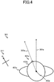
- FIG. 4 is a top view of the virtual space 301 (at time ta) before the orientations and positions of the display device 100 and the user 202 are changed in the real space 201.
- FIGS. 3A and 3B are top views of the real space 201 (at time tb) after the orientations and positions of the display device 100 and the user 202 are changed.
- FIG. 3A shows the real space 201 after the orientation of the display device 100 is changed by the user 202 rotating the orientation of the head 203 only.
- FIG. 3B shows the real space 201 after the user 202 changes the orientation of the torso 204 only.
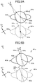
- FIGS. 5A and 5B are top views of the virtual space 301 (at time tb) after the orientations and positions of the display device 100 and the user 202 are changed in the real space 201.
- FIG. 5A shows the virtual space 301 after the user 202 changes the orientation of the display device 100 by rotating the orientation of the head 203 only.
- FIG. 5B shows the virtual space 301 after the user 202 changes the orientation of the torso 204 only.
- the description below is given with reference to these figures. Lower-case alphabetic letters are added to these figures as appropriate for expressing an elapse of time from time ta to time tb. These lower-case alphabetic letters are omitted in the following description if appropriate.
- the user 202 wears the display device 100 placed in front of the eyes of the user 202 in the real space 201.
- the display direction 205 of the display device 100 is opposite to the observation direction 302 of an avatar 401, which will be described later, in the virtual space 301 as illustrated in FIGS. 4A, 4B , 5A, and 5B .
- the user 202 is holding the controller 220.
- the controller 220 is a terminal device for manipulating the avatar 401, which is placed in the virtual space 301 and displayed on the display device 100.
- the avatar 401 is an object created by using computer graphics to represent an alter ego of the user 202 in the virtual space 301.
- the avatar 401 is human-shaped, and the position of the head 402 of the avatar 401 corresponds to an observation position 302, the eye direction of the head 402 corresponds to an observation direction 303, and the frontward direction of the torso 403 corresponds to a base direction 304.
- the controller 220 can wirelessly communicate with the display device 100 using Bluetooth®, for example.
- the user 202 inputs an instruction input indicating a moving direction of the avatar 401 to the controller 220 by operating a key or a touch panel included in the controller 220.
- the controller 220 then transmits the accepted instruction input to the display device 100.
- the display device 100 updates the observation position 302, the observation direction 303, and the base direction 304 of the avatar 401 in the virtual space 301, on the basis of the instruction input received from the controller 220 and of the orientation of the display device 100.
- azimuth directions 211 in the real space 201 may or may not match azimuth directions 311 in the virtual space 301. In the present embodiment, the azimuth directions differ between the real space and the virtual space.
- FIG. 6 is a schematic block diagram illustrating a functional configuration of the display device 100 according to the embodiment of the present disclosure.
- the display device 100 includes an accepter 111, an observation position updater 112, a detector 113, an observation direction updater 114, an obtainer 115, a base direction updater 116, a generator 117, a display unit 118, and a state information storage 121.
- the state information storage 121 stores the observation position 302, the observation direction 303, and the base direction 304 of the avatar 401 in the virtual space 301. As described later, the observation position 302, the observation direction 303, and the base direction 304 are updated by the observation position updater 112, the observation direction updater 114, and the base direction updater 116, respectively.
- the state information storage 121 is implemented by the RAM 103.
- the accepter 111 accepts an instruction input that is given to the controller 220 to indicate a moving direction.
- the accepter 111 receives, from the controller 220 via the communicator 107, a signal indicating an instruction input accepted by the controller 220.
- the control unit 101 and the communicator 107 collaborate with each other to function as the accepter 111.
- the observation position updater 112 updates the observation position 302 so that the observation position moves in the direction indicated by the input instruction relative to the base direction 304.
- the accepter 111 has received from the controller 220 an instruction input to move forward, that is, to move in the frontward direction 206a of the torso 204a from time ta to time tb, as illustrated in FIG. 2 .
- the observation position updater 112 updates, as illustrated in FIGS.
- the observation position updater 112 updates to the observation position 302b, which is frontward away from the observation position 302a by a distance V ⁇ (tb - ta).
- the time interval between time ta and time t b may be determined according to an intended application.
- the refresh interval (such as a vertical synchronization period) for the display 104 in the display device 100 may be used as the time interval.
- Time t b in one repeating unit is taken as time ta in the next repeating unit because the process is repeated as described later.
- control unit 101 functions as the observation position updater 112.
- the detector 113 detects a change in orientation of the display device 100 in the real space 201. For example, from measurements provided by the sensor 105, the detector 113 detects a change in the display direction 205 of the display device 100 relative to the reference axis in the real space 201. As the reference axis in the real space 201, either the direction of gravitational force in the real space 201 or the vertical direction of the display 104 in the display device 100 is typically adopted.
- control unit 101 and the sensor 105 collaborate with each other to function as the detector 113.
- the observation direction updater 114 updates the observation direction 303 in the virtual space 301, in accordance with the orientation of the display device 100 as detected by the detector 113.
- the observation direction updater 114 begins with obtaining an amount of rotation ⁇ around the reference axis in the real space 201, with regard to the change in the display direction 205 of the display device 100 as detected by the detector 113 from time t a to time t b .
- FIG. 2 shows that the display device 100a faces the user 202 in the display direction 205a before the user 202 changes the orientation of the head 203a.
- FIG. 3A shows that the display device 100b faces the user 202 in the display direction 205b after the user 202 changes the orientation of the head 203b.
- the angle formed between the display direction 205a and the display direction 205b is the amount of rotation ⁇ around the reference axis.
- the amount of rotation ⁇ is equivalent to the so-called yaw angle.
- the observation direction updater 114 updates the observation direction 303a to the observation direction 303b by rotating the observation direction 303a, which is stored in the state information storage 121, around the reference axis of the observation position 302a in the virtual space 301 by the amount of rotation ⁇ .
- control unit 101 functions as the observation direction updater 114.
- the obtainer 115 obtains from the controller 220 the relative position between the controller 220 and the display device 100.
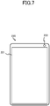
- FIG. 7 is a front view of the controller 220 according to the present embodiment.
- the controller 220 according to the present embodiment is a smart phone including a touch panel 221 and a camera 222, both disposed on the front face as illustrated in FIG. 7 .
- the touch panel 221 accepts an instruction input given by the user 202 indicating a moving direction. For example, when the user 202 slides a finger of the user 202 on the touch panel 221, the touch panel 221 detects the sliding direction and recognizes that an instruction input indicating the moving direction corresponding to the detected sliding direction has been accepted.
- the camera 222 which is an example of a sensor for detecting the display device 100, takes images of a scene in front of the camera 222. Specifically, the camera 222 takes images of a scene including the display device 100, with the camera 222 held by the user 202 as illustrated in FIGS. 2 and 3 . On the basis of the position of the display device appearing in an image taken by the camera 222, the controller 220 identifies the relative position between the controller 220 and the display device 100.
- FIG. 8 is an external view of the display device 100 worn by the user according to the present embodiment.
- the display device 100 includes markers 501 and 502 disposed at the right and left ends of the bottom.
- the controller 220 recognizes the markers 501 and 502 in an image taken by the camera 220 to identify the relative position based on the positions of the markers 501 and 502 in the image.
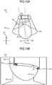
- FIGS. 9A, 9B , 10A, and 10B show examples of the relative position between the display device 100 and the controller 220 and examples of images taken by the camera 220 at the relative position.
- FIG. 9A is a top view of the display device 100 and the controller 220 when the relative position ⁇ is 0.
- the controller 220 takes an image 601 as illustrated in FIG. 9B.
- FIG. 9B shows that the markers 501 and 502 are positioned to be line-symmetrical with respect to a vertical axis of symmetry in the image 601.
- the controller 220 is capable of identifying the relative position ⁇ from positional relationships of the markers 501 and 502 in an image taken by the camera 222, by storing in advance a relative position ⁇ and positional relationships of the markers 501 and 502 in an image taken by the camera 222 at the relative position ⁇ as illustrated in FIGS. 9A and 9B and in FIGS. 10A and 10B .
- the controller 220 transmits the identified relative position ⁇ to the display device 100.
- the obtainer 115 in the display device 100 can obtain the relative position ⁇ from the controller 220 via the communicator 107.
- the base direction updater 116 updates the base direction 304, on the basis of the observation direction 303 and of the relative position obtained by the obtainer 115.
- the base direction updater 116 updates the base direction 304a to the base direction 304b by rotating, by a relative position of ⁇ 1 , the observation direction 303b, which is stored in the state information storage 121, around the reference axis of the observation position 302a, which is stored in the state information storage 121.
- the generator 117 On the basis of the observation position 302 and the observation direction 303 that are stored in the state information DB 121, the generator 117 generates an image of the virtual space 301 as observed from the observation position 302 in the observation direction 303. Specifically, the generator 117 generates an image of objects (not illustrated) placed in the virtual space, as seen from the observation position 302 in the observation direction 303, by using a technique such as perspective projection, on the basis of predetermined positions and shapes of the objects in the virtual space 301. For example, as illustrated in FIG.
- the generator 117 in the case where the user 202 changes the orientation of the display device 100 by changing the orientation of the head 203 only, the generator 117 generates, at time ta, an image of the virtual space 301 observed from the observation position 302a in the observation direction 303a indicated in FIG. 5A , and generates, at time tb, an image of the virtual space 301 observed from the observation position 302b in the observation direction 303b indicated in FIG. 5A .
- the generator 117 In the case where the user 202 changes the orientation of the torso 204 only as illustrated in FIG. 3B , the generator 117 generates, at time ta, an image of the virtual space 301 observed from the observation position 302a in the observation direction 303a indicated in FIG. 5B , and generates, at time tb, an image of the virtual space 301 observed from the observation position 302b in the observation direction 303b indicated in FIG. 5B .
- the display unit 118 shows an image generated by the generator 117 on the display 104.
- the display device 100 initializes the observation position 302 and the observation direction 303 in the virtual space 301 to a predetermined position and direction, and stores the observation position 302 and the observation direction 303 into the state information storage 121 (step S101).
- the display device 100 updates the observation position 302, which is stored in the state information storage 121, to the observation position 302, to which the observation position will be moved by a certain distance in the moving direction indicated by the accepted instruction input (step S104).
- step S105 determines whether a change in orientation of the display device 100 has been detected. If no change in orientation of the display device 100 has been detected (No in step S105), the display device 100 goes to step S107.
- step S105 If a change in orientation of the display device 100 has been detected (Yes in step S105), the display device 100 updates the observation direction 303, which is stored in the state information storage 121, in accordance with the amount of rotation ⁇ representing the detected change in orientation of the display device 100 (step S106).
- the display device 100 waits until a vertical synchronization interrupt occurs on the display 104 (step S110), and then transfers the generated image to the display 104 to present the image to the user (step S111).
- the display device 100 then returns to the processing in step S103.
- the display device 100 repeats the foregoing process until, for example, an instruction to exit the process is accepted via the operator 106. Since the display device 100 waits in step S110, the cycle period for this process is a vertical synchronization period.
- the display device 100 obtains from the controller 220 the relative position identified by the controller 220 on the basis of the position of the display device 100 appearing in an image taken by the camera 222.
- the display device 100 can obtain the relative position without using an external device such as a camera for taking an image that includes images of the controller 220 and the display device 100. Therefore, the display device 100 can be implemented in a lower-cost configuration.
- the display device 100 includes two markers 501 and 502, but the number of markers included in the display device 100 is not limited to two.
- the display device 100 may include a single marker or may include at least three markers.
- the camera 222 included in the controller 220 recognizes the markers 501 and 502 included in the display device 100, whereby the controller 220 identifies the relative position between the controller 220 and the display device 100 and transmits the identified relative position to the display device 100.
- the display device 100 may use another method to obtain the relative position.
- the display device 100 may include, instead of the markers 501 and 502, a light emitter indicating the power status of the display device 100, such as a light-emitting diode (LED).
- LED light-emitting diode
- the display device 100 may cause the light emitter to, for example, blink light in a predetermined pattern or change colors of the light so that the controller 220 can recognize the light emitter in an image taken by the camera 222, thereby identifying the relative position based on the position of the light emitter.
- the controller 220 identifies the relative position and transmits the identified relative position to the display device 100, whereby the display device 100 obtains the relative position.
- the display device 100 may use another method to obtain the relative position. For example, in a case where the display device 100 includes a camera and the controller 220 includes markers, the camera included in the display device 100, instead of the camera 222 included in the controller 220, may take an image of the controller 220, and the display device 100 may identify the relative position from the positions of the markers appearing in the taken image.
- a sensor included in one of the controller 220 and the display device 100 detects the other one of the controller 220 and the display device 100, the sensor being included in at least one of the controller 220 and the display device 100, whereby the relative position between the controller 220 and the display device 100 can be obtained.
- the display device 100 may obtain a relative position estimated from a difference between a first orientation detected by an attitude sensor included in the controller 220 and a second orientation detected by an attitude sensor included in the sensor 105 in the display device 100.
- the attitude sensor in the controller 220 detected the first orientation, which is a display direction 208a of the controller 220, while the attitude sensor included in the sensor 105 in the display device 100 detected a display direction 205a.
- the controller 220 may transmit the detected display direction 208a to the display device 100, and the display device 100 can estimate the relative position ⁇ from a difference between the received display direction 208a and the detected display direction 205a.
- the display device 100 may transmit the detected display direction 205a to the controller 220, and the controller 220 may estimate the relative position ⁇ from a difference between the detected display direction 208a and the received display direction 205a.
- the controller 220 transmits the estimated relative position ⁇ to the display device 100, whereby the display device 100 can obtain the relative position ⁇ .
- Functions according to the present disclosure can be provided in the form of the display device 100 pre-configured to implement these functions, and furthermore, an existing apparatus such as a personal computer or an information terminal device can function as the display device 100 according to the present disclosure when a program is applied to the apparatus.
- an existing apparatus such as a personal computer or an information terminal device
- the display device 100 can function as the display device 100 according to the present disclosure when a program is applied to the apparatus.
- the personal computer or the information terminal device can function as the display device 100 according to the present disclosure.
- a display method according to the present disclosure can be implemented by using the display device 100.
- the program can be applied by any appropriate method.
- a computer-readable storage medium a compact disc read-only memory (CD-ROM), a digital versatile disc (DVD), a magneto-optical disc (MO), and so on
- CD-ROM compact disc read-only memory
- DVD digital versatile disc
- MO magneto-optical disc
- the program stored in a storage on a network such as the Internet can be downloaded to be applied.
- the present disclosure achieves providing a display device, a display method, a program, and a non-temporary computer-readable information storage medium for displaying images.
Landscapes
- Engineering & Computer Science (AREA)
- Theoretical Computer Science (AREA)
- General Engineering & Computer Science (AREA)
- Physics & Mathematics (AREA)
- Human Computer Interaction (AREA)
- General Physics & Mathematics (AREA)
- Multimedia (AREA)
- Software Systems (AREA)
- Optics & Photonics (AREA)
- Radar, Positioning & Navigation (AREA)
- Remote Sensing (AREA)
- Computer Graphics (AREA)
- Computer Hardware Design (AREA)
- User Interface Of Digital Computer (AREA)
- Controls And Circuits For Display Device (AREA)
- Processing Or Creating Images (AREA)
Abstract
Description
- The present disclosure relates to a display device, a display method, a program, and a non-temporary computer-readable information storage medium.
- For a virtual reality system that provides the user with a virtual space through a head-mounted display, methods for manipulating a character (avatar), which is the user's alter ego, are made available, including, for example, detecting the user's eye direction and moving the avatar to the position at which the user is recognized as gazing on the basis of the detected eye direction (see
Patent Literature 1, for example). - PTL 1: Unexamined Japanese Patent Application Kokai Publication No.
2018-72992 - Meanwhile, the user may sometimes want to move the avatar in a direction different from the user's eye direction, such as, for example, when the avatar is walking along a wall while watching paintings on the wall in a virtual space that reproduces an art gallery. A typical method for controlling movement of a character in a virtual space may be using a terminal device such as a controller operated by the user to give an instruction about a particular moving direction for the character. However, suppose that, for example, the user's body is oriented frontward except the user's head facing sideways, and that the user intuitively gives via a terminal device an instruction about the moving direction relative to the orientation of the user's torso. In this case, when the orientation of the head-mounted display is only detectable, the instruction about the moving direction is regarded as having been given relative to the avatar's observation direction that is identified on the basis of the orientation of the head-mounted display. As a result, the avatar may be moved in a direction different from the moving direction that the user has intuitively specified.
- The present disclosure is intended to solve the aforementioned problems, and an objective of the present disclosure is to provide a display device, a display method, a program, and a non-temporary computer-readable information storage medium for enabling the observation position in a virtual space to be moved in accordance with an intuitive instruction input given by a user.
- A display device according to a first aspect of the present disclosure is a display device including:
- an accepter that accepts an instruction input indicating a moving direction, the instruction input being given to an external controller;
- a detector that detects a change in orientation of the display device;
- a storage that stores an observation position, an observation direction, and a base direction in a virtual space;
- an observation position updater that updates, upon acceptance of the instruction input, the observation position so that the observation position moves in the moving direction indicated by the instruction input relative to the base direction;
- an observation direction updater that updates the observation direction in accordance with the detected change in orientation of the display device;
- an obtainer that obtains a relative position between the controller and the display device; and
- a base direction updater that updates the base direction, based on the observation direction and on the obtained relative position.
- In the display device according to the aforementioned aspect,
the obtainer may obtain the relative position through detection performed by a sensor which is included in at least one of the controller or the display device to detect another of the at least one of the controller or the display. - In the display device according to the aforementioned aspect,
the obtainer may obtain the relative position estimated from a difference between a first orientation detected by a first attitude sensor included in the controller and a second orientation detected by a second attitude sensor included in the display device. - In the display device according to the aforementioned aspect,
the display device may further include a light emitter that shines light in a predetermined pattern, and
the obtainer may obtain from the controller the relative position that is identified by the controller based on a position of the light emitter in an image taken by a camera included in the controller and on the pattern. - A display method according to a second aspect of the present disclosure is a display method executed by a display device that includes a storage storing an observation position, an observation direction, and a base direction in a virtual space, the display method including:
- an accepting step of accepting an instruction input indicating a moving direction, the instruction input being given to an external controller;
- a detecting step of detecting a change in orientation of the display device;
- an observation position updating step of updating, upon acceptance of the instruction input, the observation position so that the observation position moves in the moving direction indicated by the instruction input relative to the base direction;
- an observation direction updating step of updating the observation direction in accordance with the detected change in orientation of the display device;
- an obtaining step of obtaining a relative position between the controller and the display device; and
- a base direction updating step of updating the base direction, based on the observation direction and on the obtained relative position.
- A program according to a third aspect of the present disclosure causes a computer that includes a storage storing an observation position, an observation direction, and a base direction in a virtual space to function as:
- an accepter that accepts an instruction input indicating a moving direction, the instruction input being given to an external controller;
- a detector that detects a change in orientation of a display device;
- an observation position updater that updates, upon acceptance of the instruction input, the observation position so that the observation position moves in the moving direction indicated by the instruction input relative to the base direction;
- an observation direction updater that updates the observation direction in accordance with the detected change in orientation of the display device;
- an obtainer that obtains a relative position between the controller and the display device; and
- a base direction updater that updates the base direction, based on the observation direction and on the obtained relative position.
- A non-temporary computer-readable information storage medium according to a fourth aspect of the present disclosure causes a computer that includes a storage storing an observation position, an observation direction, and a base direction in a virtual space to function as:
- an accepter that accepts an instruction input indicating a moving direction, the instruction input being given to an external controller;
- a detector that detects a change in orientation of a display device;
- an observation position updater that updates, upon acceptance of the instruction input, the observation position so that the observation position moves in the moving direction indicated by the instruction input relative to the base direction;
- an observation direction updater that updates the observation direction in accordance with the detected change in orientation of the display device;
- an obtainer that obtains a relative position between the controller and the display device; and
- a base direction updater that updates the base direction, based on the observation direction and on the obtained relative position.
- Note that the aforementioned information storage medium can be distributed or sold independently of computers. The non-temporary information storage medium as used herein refers to a tangible information storage medium. Examples of the non-temporary information storage medium include a compact disk, a flexible disk, a hard disk, a magnetic disk, a digital video disk, a magnetic tape, and a semiconductor memory. A temporary information storage medium refers to a transmission medium (a propagated signal) itself. Examples of the temporary storage medium include an electronic signal, an optical signal, and an electromagnetic wave. A temporary storage area refers to an area for temporarily storing data and programs, such as a random access memory (RAM) and other volatile memories.
- The present disclosure enables the observation position in a virtual space to be moved in accordance with an intuitive instruction input given by a user.
-
-
FIG. 1 is a schematic block diagram illustrating a hardware configuration of a display device according to an embodiment; -
FIG. 2 is a top view of the display device and a user in a real space before the orientations of the display device and the user are changed; -
FIG. 3A is a top view of the user and the display device after their orientations are changed in the real space by the user rotating the orientation of the head only; -
FIG. 3B is a top view of the user and the display device after their orientations are changed in the real space by the user rotating the orientation of the torso only; -
FIG. 4 is a top view of a virtual space before the orientations of the display device and the user are changed in the real space; -
FIG. 5A is a top view of the virtual space after the orientations of the display device and the user are changed in the real space by the user rotating the orientation of the head only; -
FIG. 5B is a top view of the virtual space after the orientations of the display device and the user are changed in the real space by the user rotating the orientation of the torso only; -
FIG. 6 is a schematic block diagram illustrating a functional configuration of the display device according to an embodiment; -
FIG. 7 is a front view of a controller according to an embodiment; -
FIG. 8 is an external view of the display device worn by the user according to an embodiment; -
FIG. 9A is a top view of the display device and the controller when a relative position is 0; -
FIG. 9B is an image taken by the controller in the state illustrated inFIG. 9A ; -
FIG. 10A is a top view of the display device and the controller when the relative position is ϕ1; -
FIG. 10B is an image taken by the controller in the state illustrated inFIG. 10A ; -
FIG. 11 is a flowchart illustrating a flow of a display process executed by a control unit included in the display device according to an embodiment; and -
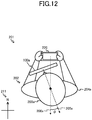
FIG. 12 is a top view of the display device and the user in the real space before their orientations are changed according to a variation. - Embodiments of the present disclosure will now be described. The embodiments are presented for explanatory purposes only and do not limit the scope of the present disclosure. Accordingly, persons skilled in the art can adopt embodiments in which any or all of the elements in the following embodiments are replaced with equivalents thereof, and such adopted embodiments are included in the scope of the present disclosure. For explaining embodiments of the present disclosure referring to the drawings, identical reference symbols are given to identical or equivalent parts throughout the drawings.
-
FIG. 1 is a schematic block diagram illustrating a hardware configuration of adisplay device 100 according to the present embodiment. Thedisplay device 100 includes, for example, a head-mounted display that has various types of sensors and a control device. The head-mounted display may be built by mounting a smart phone, a tablet computer, a phablet, or the like onto an attachment. In this case, thedisplay device 100 is implemented by executing a program causing a computer such as a smart phone to function as the aforementioned components on the computer such as a smart phone. As illustrated inFIG. 1 , thedisplay device 100 includes acontrol unit 101, a read-only memory (ROM) 102, aRAM 103, adisplay 104, asensor 105, anoperator 106, and acommunicator 107, which are connected by abus 108. - The
control unit 101, which includes, for example, a central processing unit (CPU), controls thedisplay device 100 as a whole. - The
ROM 102 is a non-volatile memory storing programs and various types of data needed for thecontrol unit 101 to control thedisplay device 100 as a whole. - The
RAM 103 is a volatile memory for temporarily storing information generated by thecontrol unit 101 and data needed for generating the information. - The
display 104, which includes a liquid crystal display (LCD), a backlight, and so on, is under control of thecontrol unit 101 to show, for example, an image output by thecontrol unit 101. - The
sensor 105, which may include an attitude sensor and an acceleration sensor, detects the orientation of thedisplay device 100. Thesensor 105 outputs a signal indicating the detected orientation of thedisplay device 100 to thecontrol unit 101. - The
operator 106 includes an input device such as a button, a keyboard, and a touch panel. Theoperator 106 accepts operations input by the user of thedisplay device 100 and outputs signals corresponding to the accepted input operations to thecontrol unit 101. - The
communicator 107 includes a communication interface for communicating with acontroller 220, which will be described later. Thecommunicator 107 communicates with thecontroller 220 under a wireless communication standard such as Bluetooth®. - The following describes a positional relationship between the
display device 100 and theuser 202 in areal space 201 and in avirtual space 301 shown on thedisplay device 100 according to the present embodiment.FIG. 2 is a top view of the real space 201 (at time ta) before the orientations and positions of thedisplay device 100 and theuser 202 are changed.FIG. 4 is a top view of the virtual space 301 (at time ta) before the orientations and positions of thedisplay device 100 and theuser 202 are changed in thereal space 201.FIGS. 3A and 3B are top views of the real space 201 (at time tb) after the orientations and positions of thedisplay device 100 and theuser 202 are changed.FIG. 3A shows thereal space 201 after the orientation of thedisplay device 100 is changed by theuser 202 rotating the orientation of thehead 203 only.FIG. 3B shows thereal space 201 after theuser 202 changes the orientation of thetorso 204 only.FIGS. 5A and 5B are top views of the virtual space 301 (at time tb) after the orientations and positions of thedisplay device 100 and theuser 202 are changed in thereal space 201.FIG. 5A shows thevirtual space 301 after theuser 202 changes the orientation of thedisplay device 100 by rotating the orientation of thehead 203 only.FIG. 5B shows thevirtual space 301 after theuser 202 changes the orientation of thetorso 204 only. The description below is given with reference to these figures. Lower-case alphabetic letters are added to these figures as appropriate for expressing an elapse of time from time ta to time tb. These lower-case alphabetic letters are omitted in the following description if appropriate. - As illustrated in
FIGS. 2 ,3A, and 3B , theuser 202 wears thedisplay device 100 placed in front of the eyes of theuser 202 in thereal space 201. When theuser 202 wears thedisplay device 100, thedisplay direction 205 of thedisplay device 100 is opposite to the observation direction 302 of an avatar 401, which will be described later, in thevirtual space 301 as illustrated inFIGS. 4A, 4B ,5A, and 5B . - In the
real space 201, theuser 202 is holding thecontroller 220. Thecontroller 220 is a terminal device for manipulating the avatar 401, which is placed in thevirtual space 301 and displayed on thedisplay device 100. The avatar 401 is an object created by using computer graphics to represent an alter ego of theuser 202 in thevirtual space 301. As illustrated inFIGS. 4A, 4B ,5A, and 5B , in the present embodiment, the avatar 401 is human-shaped, and the position of thehead 402 of the avatar 401 corresponds to an observation position 302, the eye direction of thehead 402 corresponds to an observation direction 303, and the frontward direction of the torso 403 corresponds to a base direction 304. Thecontroller 220 can wirelessly communicate with thedisplay device 100 using Bluetooth®, for example. For instance, theuser 202 inputs an instruction input indicating a moving direction of the avatar 401 to thecontroller 220 by operating a key or a touch panel included in thecontroller 220. Thecontroller 220 then transmits the accepted instruction input to thedisplay device 100. As described later, thedisplay device 100 updates the observation position 302, the observation direction 303, and the base direction 304 of the avatar 401 in thevirtual space 301, on the basis of the instruction input received from thecontroller 220 and of the orientation of thedisplay device 100. - Note that
azimuth directions 211 in thereal space 201 may or may not matchazimuth directions 311 in thevirtual space 301. In the present embodiment, the azimuth directions differ between the real space and the virtual space. -
FIG. 6 is a schematic block diagram illustrating a functional configuration of thedisplay device 100 according to the embodiment of the present disclosure. As shown inFIG. 6 , thedisplay device 100 includes anaccepter 111, anobservation position updater 112, a detector 113, anobservation direction updater 114, anobtainer 115, abase direction updater 116, agenerator 117, adisplay unit 118, and astate information storage 121. - The
state information storage 121 stores the observation position 302, the observation direction 303, and the base direction 304 of the avatar 401 in thevirtual space 301. As described later, the observation position 302, the observation direction 303, and the base direction 304 are updated by theobservation position updater 112, theobservation direction updater 114, and thebase direction updater 116, respectively. Thestate information storage 121 is implemented by theRAM 103. - The
accepter 111 accepts an instruction input that is given to thecontroller 220 to indicate a moving direction. For example, theaccepter 111 receives, from thecontroller 220 via thecommunicator 107, a signal indicating an instruction input accepted by thecontroller 220. In the present embodiment, thecontrol unit 101 and thecommunicator 107 collaborate with each other to function as theaccepter 111. - When the
accepter 111 accepts an instruction input, theobservation position updater 112 updates the observation position 302 so that the observation position moves in the direction indicated by the input instruction relative to the base direction 304. As an example, suppose that theaccepter 111 has received from thecontroller 220 an instruction input to move forward, that is, to move in thefrontward direction 206a of thetorso 204a from time ta to time tb, as illustrated inFIG. 2 . Then, theobservation position updater 112 updates, as illustrated inFIGS. 5A and 5B , thecurrent observation position 302a stored in thestate information storage 121 to theobservation position 302b, to which theobservation position 302a will be moved forward along thebase direction 304a at velocity V relative to thecurrent base direction 304a stored in thestatus information storage 121. In other words, theobservation position updater 112 updates to theobservation position 302b, which is frontward away from theobservation position 302a by a distance V × (tb - ta). - The time interval between time ta and time tb may be determined according to an intended application. For example, the refresh interval (such as a vertical synchronization period) for the
display 104 in thedisplay device 100 may be used as the time interval. Time tb in one repeating unit is taken as time ta in the next repeating unit because the process is repeated as described later. - In the present embodiment, the
control unit 101 functions as theobservation position updater 112. - The detector 113 detects a change in orientation of the
display device 100 in thereal space 201. For example, from measurements provided by thesensor 105, the detector 113 detects a change in thedisplay direction 205 of thedisplay device 100 relative to the reference axis in thereal space 201. As the reference axis in thereal space 201, either the direction of gravitational force in thereal space 201 or the vertical direction of thedisplay 104 in thedisplay device 100 is typically adopted. - In the present embodiment, the
control unit 101 and thesensor 105 collaborate with each other to function as the detector 113. - The
observation direction updater 114 updates the observation direction 303 in thevirtual space 301, in accordance with the orientation of thedisplay device 100 as detected by the detector 113. For example, theobservation direction updater 114 begins with obtaining an amount of rotation θ around the reference axis in thereal space 201, with regard to the change in thedisplay direction 205 of thedisplay device 100 as detected by the detector 113 from time ta to time tb. Specifically,FIG. 2 shows that thedisplay device 100a faces theuser 202 in thedisplay direction 205a before theuser 202 changes the orientation of thehead 203a.FIG. 3A shows that thedisplay device 100b faces theuser 202 in thedisplay direction 205b after theuser 202 changes the orientation of thehead 203b. The angle formed between thedisplay direction 205a and thedisplay direction 205b is the amount of rotation θ around the reference axis. The amount of rotation θ is equivalent to the so-called yaw angle. - Then, as illustrated in
FIG. 5A , theobservation direction updater 114 updates theobservation direction 303a to theobservation direction 303b by rotating theobservation direction 303a, which is stored in thestate information storage 121, around the reference axis of theobservation position 302a in thevirtual space 301 by the amount of rotation θ. - In the present embodiment, the
control unit 101 functions as theobservation direction updater 114. - The
obtainer 115 obtains from thecontroller 220 the relative position between thecontroller 220 and thedisplay device 100. - The following describes an example method for obtaining the relative position in the present embodiment.
FIG. 7 is a front view of thecontroller 220 according to the present embodiment. Thecontroller 220 according to the present embodiment is a smart phone including atouch panel 221 and acamera 222, both disposed on the front face as illustrated inFIG. 7 . Thetouch panel 221 accepts an instruction input given by theuser 202 indicating a moving direction. For example, when theuser 202 slides a finger of theuser 202 on thetouch panel 221, thetouch panel 221 detects the sliding direction and recognizes that an instruction input indicating the moving direction corresponding to the detected sliding direction has been accepted. Thecamera 222, which is an example of a sensor for detecting thedisplay device 100, takes images of a scene in front of thecamera 222. Specifically, thecamera 222 takes images of a scene including thedisplay device 100, with thecamera 222 held by theuser 202 as illustrated inFIGS. 2 and3 . On the basis of the position of the display device appearing in an image taken by thecamera 222, thecontroller 220 identifies the relative position between thecontroller 220 and thedisplay device 100. - The following describes in detail an example method for identifying the relative position based on the position of the display device in an image taken by the
camera 222.FIG. 8 is an external view of thedisplay device 100 worn by the user according to the present embodiment. As shown inFIG. 8 , thedisplay device 100 includesmarkers controller 220 recognizes themarkers camera 220 to identify the relative position based on the positions of themarkers controller 220 is always positioned in front of theuser 202, and the relative position ϕ to be identified is defined as an angle formed between thedisplay direction 205 and areference direction 207, which is thedisplay direction 205 of thedisplay device 100 worn by theuser 202 facing frontward.FIGS. 9A, 9B ,10A, and 10B show examples of the relative position between thedisplay device 100 and thecontroller 220 and examples of images taken by thecamera 220 at the relative position.FIG. 9A is a top view of thedisplay device 100 and thecontroller 220 when the relative position ϕ is 0. At this relative position, thecontroller 220 takes animage 601 as illustrated inFIG. 9B. FIG. 9B shows that themarkers image 601. -
FIG. 10A is a top view of thedisplay device 100 and thecontroller 220 when the relative position ϕ = ϕ1 (ϕ1 > 0). At this relative position, thecontroller 220 takes animage 602 as illustrated inFIG. 10B. FIG. 10B shows that themarkers markers image 601 inFIG. 9B . - The
controller 220 is capable of identifying the relative position ϕ from positional relationships of themarkers camera 222, by storing in advance a relative position ϕ and positional relationships of themarkers camera 222 at the relative position ϕ as illustrated inFIGS. 9A and 9B and inFIGS. 10A and 10B . Thecontroller 220 transmits the identified relative position ϕ to thedisplay device 100. Thus, theobtainer 115 in thedisplay device 100 can obtain the relative position ϕ from thecontroller 220 via thecommunicator 107. - In the present embodiment, the
control unit 101 and thecommunicator 107 collaborate with each other to function as theobtainer 115. - The
base direction updater 116 updates the base direction 304, on the basis of the observation direction 303 and of the relative position obtained by theobtainer 115. - By way of example, the following describes an update of the base direction in the case where the
obtainer 115 has obtained, from thecontroller 220, a relative position ϕ, which is an angle formed between thereference direction 207 and thedisplay direction 205. For example, when theobtainer 115 obtains from thecontroller 220 the relative position ϕ = ϕ1 as of time tb, thebase direction updater 116 determines thebase direction 304b so as to form an angle ϕ1 with theobservation direction 303b as illustrated inFIG. 5B , because a relative position ϕ corresponds to an angle formed between the observation direction 303 and the base direction 304 in thevirtual space 301. In other words, thebase direction updater 116 updates thebase direction 304a to thebase direction 304b by rotating, by a relative position of ϕ1, theobservation direction 303b, which is stored in thestate information storage 121, around the reference axis of theobservation position 302a, which is stored in thestate information storage 121. - In the present embodiment, the
control unit 101 functions as thebase direction updater 116. - On the basis of the observation position 302 and the observation direction 303 that are stored in the
state information DB 121, thegenerator 117 generates an image of thevirtual space 301 as observed from the observation position 302 in the observation direction 303. Specifically, thegenerator 117 generates an image of objects (not illustrated) placed in the virtual space, as seen from the observation position 302 in the observation direction 303, by using a technique such as perspective projection, on the basis of predetermined positions and shapes of the objects in thevirtual space 301. For example, as illustrated inFIG. 3A , in the case where theuser 202 changes the orientation of thedisplay device 100 by changing the orientation of thehead 203 only, thegenerator 117 generates, at time ta, an image of thevirtual space 301 observed from theobservation position 302a in theobservation direction 303a indicated inFIG. 5A , and generates, at time tb, an image of thevirtual space 301 observed from theobservation position 302b in theobservation direction 303b indicated inFIG. 5A . In the case where theuser 202 changes the orientation of thetorso 204 only as illustrated inFIG. 3B , thegenerator 117 generates, at time ta, an image of thevirtual space 301 observed from theobservation position 302a in theobservation direction 303a indicated inFIG. 5B , and generates, at time tb, an image of thevirtual space 301 observed from theobservation position 302b in theobservation direction 303b indicated inFIG. 5B . - In the present embodiment, the
control unit 101 functions as thegenerator 117. - The
display unit 118 shows an image generated by thegenerator 117 on thedisplay 104. - In the present embodiment, the
control unit 101 and thedisplay 104 collaborate with each other to function as thedisplay unit 118. - The following describes operations of the
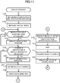
display device 100 according to the embodiment of the present disclosure.FIG. 11 is a flowchart illustrating a flow of a display process executed by thecontrol unit 101 in thedisplay device 100. Start of the process is triggered by, for example, acceptance of an instruction to start the process via theoperator 106. - First, the
display device 100 initializes the observation position 302 and the observation direction 303 in thevirtual space 301 to a predetermined position and direction, and stores the observation position 302 and the observation direction 303 into the state information storage 121 (step S101). - Next, the
display device 100 initializes the virtual space 301 (step S102). During the initialization, thedisplay device 100 makes settings, including, for example, obtaining and setting the position, shape, orientation, and appearance of an object to be placed in thevirtual space 301, and obtaining and setting an image of the background supposed to be placed at an infinite distance in thevirtual space 301. - The
display device 100 then determines whether an instruction input has been accepted from the controller 220 (step S103). If no instruction input has been accepted from the controller (No in step S103), thedisplay device 100 goes to step S105. - If an instruction input has been accepted from the controller (Yes in step S103), the
display device 100 updates the observation position 302, which is stored in thestate information storage 121, to the observation position 302, to which the observation position will be moved by a certain distance in the moving direction indicated by the accepted instruction input (step S104). - Then, the
display device 100 determines whether a change in orientation of thedisplay device 100 has been detected (step S105). If no change in orientation of thedisplay device 100 has been detected (No in step S105), thedisplay device 100 goes to step S107. - If a change in orientation of the
display device 100 has been detected (Yes in step S105), thedisplay device 100 updates the observation direction 303, which is stored in thestate information storage 121, in accordance with the amount of rotation θ representing the detected change in orientation of the display device 100 (step S106). - Next, the
display device 100 obtains the relative position between thecontroller 220 and the display device 100 (step S107). On the basis of the observation direction 303, which is stored in thestate information storage 121, and of the obtained relative position, thedisplay device 100 updates the base direction 304, which is stored in the state information storage 121 (step S108). - Then, the
display device 100 generates an image of thevirtual space 301 observed in the observation direction 303 from the observation position 302, as stored in the state information storage 121 (step S109). - After that, the
display device 100 waits until a vertical synchronization interrupt occurs on the display 104 (step S110), and then transfers the generated image to thedisplay 104 to present the image to the user (step S111). - Then, the
display device 100 updates the state of the virtual space 301 (step S112). For example, in the case where thevirtual space 301 is created by computer graphics that change with time, thedisplay device 100 conducts a physical simulation by which the position and orientation of an object are updated in accordance with the velocity, acceleration, angular velocity, angular acceleration, and the like that are set to the object, or deforms an object in accordance with predetermined conditions. - The
display device 100 then returns to the processing in step S103. Thedisplay device 100 repeats the foregoing process until, for example, an instruction to exit the process is accepted via theoperator 106. Since thedisplay device 100 waits in step S110, the cycle period for this process is a vertical synchronization period. - As described above, upon acceptance of an instruction input indicating the moving direction given via the
controller 220, thedisplay device 100 according to the embodiment of the present disclosure updates the observation position of the avatar so that the observation position moves in the moving direction indicated by the instruction input relative to the base direction of the avatar 401. In addition, thedisplay device 100 obtains the relative position between thecontroller 220 and thedisplay device 100 by identifying the position of thedisplay device 100 appearing in an image taken by thecamera 222 included in thecontroller 220. Then, thedisplay device 100 updates the base direction, on the basis of the observation direction of the avatar 401 as updated in accordance with the change in orientation of the display device detected by thesensor 105 and of the obtained relative position. Thus, the observation direction 302, which represents the orientation of thehead 402 of the avatar 401 in thevirtual space 301, and the base direction 304, which represents the orientation of the torso 403 of the avatar, are managed independently by thedisplay device 100. Therefore, even when the user intuitively inputs to thecontroller 220 an instruction input indicating the moving direction relative to the frontward direction 206 of thetorso 204 of the user, thedisplay device 100 is capable of moving the observation position 302 in the virtual space in accordance with such intuitive instruction input given by the user. - In addition, the
display device 100 obtains from thecontroller 220 the relative position identified by thecontroller 220 on the basis of the position of thedisplay device 100 appearing in an image taken by thecamera 222. Thus, thedisplay device 100 can obtain the relative position without using an external device such as a camera for taking an image that includes images of thecontroller 220 and thedisplay device 100. Therefore, thedisplay device 100 can be implemented in a lower-cost configuration. - Embodiments of the present disclosure have been described above, but these embodiments are examples only and the scope of the present disclosure is not limited thereto. In other words, the present disclosure allows for various applications and every possible embodiment is included in the scope of the present disclosure.
- For example, in the example described in the foregoing embodiment, the
display device 100 includes twomarkers display device 100 is not limited to two. Thedisplay device 100 may include a single marker or may include at least three markers. - In the example described in the foregoing embodiment, the
camera 222 included in thecontroller 220 recognizes themarkers display device 100, whereby thecontroller 220 identifies the relative position between thecontroller 220 and thedisplay device 100 and transmits the identified relative position to thedisplay device 100. However, thedisplay device 100 may use another method to obtain the relative position. For example, thedisplay device 100 may include, instead of themarkers display device 100, such as a light-emitting diode (LED). In this case, thedisplay device 100 may cause the light emitter to, for example, blink light in a predetermined pattern or change colors of the light so that thecontroller 220 can recognize the light emitter in an image taken by thecamera 222, thereby identifying the relative position based on the position of the light emitter. - In the example described in the foregoing embodiment, the
controller 220 identifies the relative position and transmits the identified relative position to thedisplay device 100, whereby thedisplay device 100 obtains the relative position. However, thedisplay device 100 may use another method to obtain the relative position. For example, in a case where thedisplay device 100 includes a camera and thecontroller 220 includes markers, the camera included in thedisplay device 100, instead of thecamera 222 included in thecontroller 220, may take an image of thecontroller 220, and thedisplay device 100 may identify the relative position from the positions of the markers appearing in the taken image. In other words, a sensor included in one of thecontroller 220 and thedisplay device 100 detects the other one of thecontroller 220 and thedisplay device 100, the sensor being included in at least one of thecontroller 220 and thedisplay device 100, whereby the relative position between thecontroller 220 and thedisplay device 100 can be obtained. - When the
camera 222 in thecontroller 220 is unable to detect thedisplay device 100 in the foregoing embodiment, such as, for example, when themarkers camera 222 in thecontroller 220, thedisplay device 100 may obtain a relative position estimated from a difference between a first orientation detected by an attitude sensor included in thecontroller 220 and a second orientation detected by an attitude sensor included in thesensor 105 in thedisplay device 100. Suppose that, as illustrated in an example inFIG. 12 , at time ta, the attitude sensor in thecontroller 220 detected the first orientation, which is adisplay direction 208a of thecontroller 220, while the attitude sensor included in thesensor 105 in thedisplay device 100 detected adisplay direction 205a. Then, thecontroller 220 may transmit the detecteddisplay direction 208a to thedisplay device 100, and thedisplay device 100 can estimate the relative position ϕ from a difference between the receiveddisplay direction 208a and the detecteddisplay direction 205a. Alternatively, thedisplay device 100 may transmit the detecteddisplay direction 205a to thecontroller 220, and thecontroller 220 may estimate the relative position ϕ from a difference between the detecteddisplay direction 208a and the receiveddisplay direction 205a. In this case, thecontroller 220 transmits the estimated relative position ϕ to thedisplay device 100, whereby thedisplay device 100 can obtain the relative position ϕ. - Functions according to the present disclosure can be provided in the form of the
display device 100 pre-configured to implement these functions, and furthermore, an existing apparatus such as a personal computer or an information terminal device can function as thedisplay device 100 according to the present disclosure when a program is applied to the apparatus. In other words, by applying a program for implementing the individual functional components of thedisplay device 100 illustrated in the foregoing embodiment to an existing personal computer or information terminal device in such a way that the program can be executed by the CPU or the like that controls the existing personal computer or information terminal device, the personal computer or the information terminal device can function as thedisplay device 100 according to the present disclosure. A display method according to the present disclosure can be implemented by using thedisplay device 100. - In addition to the aforementioned method, the program can be applied by any appropriate method. For example, the program stored in a computer-readable storage medium (a compact disc read-only memory (CD-ROM), a digital versatile disc (DVD), a magneto-optical disc (MO), and so on) can be applied, or the program stored in a storage on a network such as the Internet can be downloaded to be applied.
- The foregoing describes some example embodiments for explanatory purposes. Although the foregoing discussion has presented specific embodiments, persons skilled in the art will recognize that changes may be made in form and detail without departing from the broader spirit and scope of the invention. Accordingly, the specification and drawings are to be regarded in an illustrative rather than a restrictive sense. This detailed description, therefore, is not to be taken in a limiting sense, and the scope of the invention is defined only by the included claims, along with the full range of equivalents to which such claims are entitled.
- The present disclosure achieves providing a display device, a display method, a program, and a non-temporary computer-readable information storage medium for displaying images.
-
- 100 (100a, 100b)
- Display device
- 101
- Control unit
- 102
- ROM
- 103
- RAM
- 104
- Display
- 105
- Sensor
- 106
- Operator
- 107
- Communicator
- 108
- Bus
- 111
- Accepter
- 112
- Observation position updater
- 113
- Detector
- 114
- Observation direction updater
- 115
- Obtainer
- 116
- Base direction updater
- 117
- Generator
- 118
- Display unit
- 121
- State information storage
- 201
- Real space
- 202
- User
- 203 (203a, 203b)
- User's head
- 204 (204a, 204b)
- User's torso
- 205 (205a, 205b)
- Display direction of display device
- 206 (206a, 206b)
- Frontward direction
- 207 (207a, 207b)
- Reference direction
- 208a
- Display direction of controller
- 211
- Azimuth directions in real space
- 220
- Controller
- 221
- Touch panel
- 222
- Camera
- 301
- Virtual space
- 302 (302a, 302b)
- Observation position
- 303 (303a, 303b)
- Observation direction
- 304 (304a, 304b)
- Base direction
- 311
- Azimuth directions in virtual space
- 401 (401a, 401b)
- Avatar
- 402 (402a, 402b)
- Avatar's head
- 403 (403a, 403b)
- Avatar's torso
- 501, 502
- Marker
- 601, 602
- Image
Claims (7)
- A display device comprising:an accepter that accepts an instruction input indicating a moving direction, the instruction input being given to an external controller;a detector that detects a change in orientation of the display device;a storage that stores an observation position, an observation direction, and a base direction in a virtual space;an observation position updater that updates, upon acceptance of the instruction input, the observation position so that the observation position moves in the moving direction indicated by the instruction input relative to the base direction;an observation direction updater that updates the observation direction in accordance with the detected change in orientation of the display device;an obtainer that obtains a relative position between the controller and the display device; anda base direction updater that updates the base direction, based on the observation direction and on the obtained relative position.
- The display device according to claim 1,
wherein the obtainer obtains the relative position through detection performed by a sensor included in at least one of the controller or display device to detect another of the at least one of the controller or the display device. - The display device according to claim 1,
wherein the obtainer obtains the relative position estimated from a difference between a first orientation detected by a first attitude sensor included in the controller and a second orientation detected by a second attitude sensor included in the display device. - The display device according to claim 1, further comprising:a light emitter that shines light in a predetermined pattern,wherein the obtainer obtains from the controller the relative position that is identified by the controller based on a position of the light emitter in an image taken by a camera included in the controller and on the pattern.
- A display method executed by a display device that comprises a storage storing an observation position, an observation direction, and a base direction in a virtual space, the display method comprising:an accepting step of accepting an instruction input indicating a moving direction, the instruction input being given to an external controller;a detecting step of detecting a change in orientation of the display device;an observation position updating step of updating, upon acceptance of the instruction input, the observation position so that the observation position moves in the moving direction indicated by the instruction input relative to the base direction;an observation direction updating step of updating the observation direction in accordance with the detected change in orientation of the display device;an obtaining step of obtaining a relative position between the controller and the display device; anda base direction updating step of updating the base direction, based on the observation direction and on the obtained relative position.
- A program causing a computer that comprises a storage storing an observation position, an observation direction, and a base direction in a virtual space to function as:an accepter that accepts an instruction input indicating a moving direction, the instruction input being given to an external controller;a detector that detects a change in orientation of a display device;an observation position updater that updates, upon acceptance of the instruction input, the observation position so that the observation position moves in the moving direction indicated by the instruction input relative to the base direction;an observation direction updater that updates the observation direction in accordance with the detected change in orientation of the display device;an obtainer that obtains a relative position between the controller and the display device; anda base direction updater that updates the base direction, based on the observation direction and on the obtained relative position.
- A non-temporary computer-readable information storage medium recording a program causing a computer that comprises a storage storing an observation position, an observation direction, and a base direction in a virtual space to function as:an accepter that accepts an instruction input indicating a moving direction, the instruction input being given to an external controller;a detector that detects a change in orientation of a display device;an observation position updater that updates, upon acceptance of the instruction input, the observation position so that the observation position moves in the moving direction indicated by the instruction input relative to the base direction;an observation direction updater that updates the observation direction in accordance with the detected change in orientation of the display device;an obtainer that obtains a relative position between the controller and the display device; anda base direction updater that updates the base direction, based on the observation direction and on the obtained relative position.
Applications Claiming Priority (1)
| Application Number | Priority Date | Filing Date | Title |
|---|---|---|---|
| PCT/JP2018/028874 WO2020026380A1 (en) | 2018-08-01 | 2018-08-01 | Display device, display method, program, and non-temporary computer-readable information storage medium |
Publications (3)
| Publication Number | Publication Date |
|---|---|
| EP3677995A1 true EP3677995A1 (en) | 2020-07-08 |
| EP3677995A4 EP3677995A4 (en) | 2020-09-30 |
| EP3677995B1 EP3677995B1 (en) | 2021-10-06 |
Family
ID=66625545
Family Applications (1)
| Application Number | Title | Priority Date | Filing Date |
|---|---|---|---|
| EP18928946.5A Active EP3677995B1 (en) | 2018-08-01 | 2018-08-01 | Display device, display method, program, and non-temporary computer-readable information storage medium |
Country Status (5)
| Country | Link |
|---|---|
| US (1) | US11321920B2 (en) |
| EP (1) | EP3677995B1 (en) |
| JP (1) | JP6518028B1 (en) |
| ES (1) | ES2896704T3 (en) |
| WO (1) | WO2020026380A1 (en) |
Families Citing this family (2)
| Publication number | Priority date | Publication date | Assignee | Title |
|---|---|---|---|---|
| JP7517161B2 (en) * | 2021-01-15 | 2024-07-17 | オムロン株式会社 | Information presentation system, terminal device and program |
| US11977672B2 (en) * | 2022-06-03 | 2024-05-07 | Qualcomm Incorporated | Distributed pose prediction |
Family Cites Families (10)
| Publication number | Priority date | Publication date | Assignee | Title |
|---|---|---|---|---|
| US9268136B1 (en) | 2012-09-28 | 2016-02-23 | Google Inc. | Use of comparative sensor data to determine orientation of head relative to body |
| JP2015223334A (en) * | 2014-05-28 | 2015-12-14 | 株式会社デンソー | Display system |
| US10310595B2 (en) * | 2014-06-30 | 2019-06-04 | Sony Corporation | Information processing apparatus, information processing method, computer program, and image processing system |
| JP2016158795A (en) * | 2015-02-27 | 2016-09-05 | 株式会社ソニー・インタラクティブエンタテインメント | Display control program, display control apparatus, and display control method |
| US10684485B2 (en) * | 2015-03-06 | 2020-06-16 | Sony Interactive Entertainment Inc. | Tracking system for head mounted display |
| US10146334B2 (en) * | 2016-06-09 | 2018-12-04 | Microsoft Technology Licensing, Llc | Passive optical and inertial tracking in slim form-factor |
| US20180024623A1 (en) * | 2016-07-22 | 2018-01-25 | Google Inc. | Detecting user range of motion for virtual reality user interfaces |
| JP6523233B2 (en) | 2016-10-26 | 2019-05-29 | 株式会社コロプラ | Information processing method, apparatus, and program for causing a computer to execute the information processing method |
| JP2018072604A (en) * | 2016-10-31 | 2018-05-10 | 株式会社コロプラ | Method for suppressing VR sickness, program for causing computer to execute the method, and information processing apparatus |
| WO2019084325A1 (en) * | 2017-10-27 | 2019-05-02 | Magic Leap, Inc. | Virtual reticle for augmented reality systems |
-
2018
- 2018-08-01 WO PCT/JP2018/028874 patent/WO2020026380A1/en not_active Ceased
- 2018-08-01 JP JP2019515374A patent/JP6518028B1/en active Active
- 2018-08-01 EP EP18928946.5A patent/EP3677995B1/en active Active
- 2018-08-01 US US16/648,019 patent/US11321920B2/en active Active
- 2018-08-01 ES ES18928946T patent/ES2896704T3/en active Active
Also Published As
| Publication number | Publication date |
|---|---|
| JPWO2020026380A1 (en) | 2020-08-06 |
| WO2020026380A1 (en) | 2020-02-06 |
| US11321920B2 (en) | 2022-05-03 |
| JP6518028B1 (en) | 2019-05-22 |
| EP3677995B1 (en) | 2021-10-06 |
| US20200279437A1 (en) | 2020-09-03 |
| EP3677995A4 (en) | 2020-09-30 |
| ES2896704T3 (en) | 2022-02-25 |
Similar Documents
| Publication | Publication Date | Title |
|---|---|---|
| EP4272064B1 (en) | Micro hand gestures for controlling virtual and graphical elements | |
| US20250199647A1 (en) | External user interface for head worn computing | |
| US12353646B2 (en) | Augmented reality eyewear 3D painting | |
| EP4530701A2 (en) | Beacons for localization and content delivery to wearable devices | |
| CN115768537B (en) | Interactive augmented reality experience using location tracking | |
| CN110647237B (en) | Gesture-based content sharing in an artificial reality environment | |
| US20210294415A1 (en) | External user interface for head worn computing | |
| CN114402589B (en) | Smart stylus beam and auxiliary probability input for element mapping in 2D and 3D graphical user interfaces | |
| CN117120962A (en) | Bimanual interaction between mapped hand areas for controlling virtual and graphical elements | |
| US20170336872A1 (en) | External user interface for head worn computing | |
| US11907417B2 (en) | Glance and reveal within a virtual environment | |
| WO2017051595A1 (en) | Information processing device, information processing method and program | |
| WO2017015093A1 (en) | External user interface for head worn computing | |
| US20180032230A1 (en) | Information processing method and system for executing the information processing method | |
| JP2018072992A (en) | Information processing method and equipment and program making computer execute the information processing method | |
| CN119790372A (en) | Scissor hand gesture for collaborative targeting | |
| KR20230112729A (en) | Augmented reality spatial audio experience | |
| JP2018018326A (en) | Information processing method and program for causing computer to execute information processing method | |
| US11321920B2 (en) | Display device, display method, program, and non-temporary computer-readable information storage medium | |
| US12026302B2 (en) | Controlling a device setting using head pose | |
| JP6118444B1 (en) | Information processing method and program for causing computer to execute information processing method | |
| JP6469752B2 (en) | INFORMATION PROCESSING METHOD, INFORMATION PROCESSING PROGRAM, INFORMATION PROCESSING SYSTEM, AND INFORMATION PROCESSING APPARATUS | |
| EP4049118A1 (en) | Eye-based activation and tool selection systems and methods | |
| JP2019192250A (en) | Information processing method, apparatus, and program causing computer to execute the method | |
| CN119816800A (en) | Virtual interface for controlling IoT devices |
Legal Events
| Date | Code | Title | Description |
|---|---|---|---|
| STAA | Information on the status of an ep patent application or granted ep patent |
Free format text: STATUS: THE INTERNATIONAL PUBLICATION HAS BEEN MADE |
|
| PUAI | Public reference made under article 153(3) epc to a published international application that has entered the european phase |
Free format text: ORIGINAL CODE: 0009012 |
|
| STAA | Information on the status of an ep patent application or granted ep patent |
Free format text: STATUS: REQUEST FOR EXAMINATION WAS MADE |
|
| 17P | Request for examination filed |
Effective date: 20200330 |
|
| AK | Designated contracting states |
Kind code of ref document: A1 Designated state(s): AL AT BE BG CH CY CZ DE DK EE ES FI FR GB GR HR HU IE IS IT LI LT LU LV MC MK MT NL NO PL PT RO RS SE SI SK SM TR |
|
| AX | Request for extension of the european patent |
Extension state: BA ME |
|
| A4 | Supplementary search report drawn up and despatched |
Effective date: 20200901 |
|
| RIC1 | Information provided on ipc code assigned before grant |
Ipc: G06F 3/0346 20130101ALI20200826BHEP Ipc: A63F 13/211 20140101ALI20200826BHEP Ipc: G06T 15/20 20110101ALI20200826BHEP Ipc: G06F 3/03 20060101ALI20200826BHEP Ipc: G06F 3/0481 20130101ALI20200826BHEP Ipc: G02B 27/01 20060101ALI20200826BHEP Ipc: G06F 3/01 20060101AFI20200826BHEP Ipc: G06T 19/00 20110101ALI20200826BHEP |
|
| GRAP | Despatch of communication of intention to grant a patent |
Free format text: ORIGINAL CODE: EPIDOSNIGR1 |
|
| STAA | Information on the status of an ep patent application or granted ep patent |
Free format text: STATUS: GRANT OF PATENT IS INTENDED |
|
| RIC1 | Information provided on ipc code assigned before grant |
Ipc: G06F 3/01 20060101AFI20210407BHEP Ipc: G06F 3/0481 20130101ALI20210407BHEP Ipc: A63F 13/211 20140101ALI20210407BHEP Ipc: G06T 19/00 20110101ALI20210407BHEP Ipc: G02B 27/01 20060101ALI20210407BHEP Ipc: G06F 3/03 20060101ALI20210407BHEP Ipc: G06F 3/0346 20130101ALI20210407BHEP Ipc: G06T 15/20 20110101ALI20210407BHEP Ipc: A63F 13/213 20140101ALI20210407BHEP Ipc: A63F 13/5258 20140101ALI20210407BHEP Ipc: G02B 27/00 20060101ALI20210407BHEP |
|
| DAV | Request for validation of the european patent (deleted) | ||
| DAX | Request for extension of the european patent (deleted) | ||
| INTG | Intention to grant announced |
Effective date: 20210422 |
|
| GRAJ | Information related to disapproval of communication of intention to grant by the applicant or resumption of examination proceedings by the epo deleted |
Free format text: ORIGINAL CODE: EPIDOSDIGR1 |
|
| STAA | Information on the status of an ep patent application or granted ep patent |
Free format text: STATUS: REQUEST FOR EXAMINATION WAS MADE |
|
| INTC | Intention to grant announced (deleted) | ||
| GRAP | Despatch of communication of intention to grant a patent |
Free format text: ORIGINAL CODE: EPIDOSNIGR1 |
|
| STAA | Information on the status of an ep patent application or granted ep patent |
Free format text: STATUS: GRANT OF PATENT IS INTENDED |
|
| INTG | Intention to grant announced |
Effective date: 20210727 |
|
| RAP3 | Party data changed (applicant data changed or rights of an application transferred) |
Owner name: RAKUTEN GROUP, INC. |
|
| GRAS | Grant fee paid |
Free format text: ORIGINAL CODE: EPIDOSNIGR3 |
|
| GRAA | (expected) grant |
Free format text: ORIGINAL CODE: 0009210 |
|
| STAA | Information on the status of an ep patent application or granted ep patent |
Free format text: STATUS: THE PATENT HAS BEEN GRANTED |
|
| AK | Designated contracting states |
Kind code of ref document: B1 Designated state(s): AL AT BE BG CH CY CZ DE DK EE ES FI FR GB GR HR HU IE IS IT LI LT LU LV MC MK MT NL NO PL PT RO RS SE SI SK SM TR |
|
| REG | Reference to a national code |
Ref country code: GB Ref legal event code: FG4D |
|
| REG | Reference to a national code |
Ref country code: CH Ref legal event code: EP Ref country code: AT Ref legal event code: REF Ref document number: 1436791 Country of ref document: AT Kind code of ref document: T Effective date: 20211015 |
|
| REG | Reference to a national code |
Ref country code: IE Ref legal event code: FG4D |
|
| REG | Reference to a national code |
Ref country code: DE Ref legal event code: R096 Ref document number: 602018024861 Country of ref document: DE |
|
| REG | Reference to a national code |
Ref country code: LT Ref legal event code: MG9D |
|
| REG | Reference to a national code |
Ref country code: NL Ref legal event code: MP Effective date: 20211006 |
|
| REG | Reference to a national code |
Ref country code: ES Ref legal event code: FG2A Ref document number: 2896704 Country of ref document: ES Kind code of ref document: T3 Effective date: 20220225 |
|
| PG25 | Lapsed in a contracting state [announced via postgrant information from national office to epo] |
Ref country code: RS Free format text: LAPSE BECAUSE OF FAILURE TO SUBMIT A TRANSLATION OF THE DESCRIPTION OR TO PAY THE FEE WITHIN THE PRESCRIBED TIME-LIMIT Effective date: 20211006 Ref country code: LT Free format text: LAPSE BECAUSE OF FAILURE TO SUBMIT A TRANSLATION OF THE DESCRIPTION OR TO PAY THE FEE WITHIN THE PRESCRIBED TIME-LIMIT Effective date: 20211006 Ref country code: FI Free format text: LAPSE BECAUSE OF FAILURE TO SUBMIT A TRANSLATION OF THE DESCRIPTION OR TO PAY THE FEE WITHIN THE PRESCRIBED TIME-LIMIT Effective date: 20211006 Ref country code: BG Free format text: LAPSE BECAUSE OF FAILURE TO SUBMIT A TRANSLATION OF THE DESCRIPTION OR TO PAY THE FEE WITHIN THE PRESCRIBED TIME-LIMIT Effective date: 20220106 |
|
| PG25 | Lapsed in a contracting state [announced via postgrant information from national office to epo] |
Ref country code: IS Free format text: LAPSE BECAUSE OF FAILURE TO SUBMIT A TRANSLATION OF THE DESCRIPTION OR TO PAY THE FEE WITHIN THE PRESCRIBED TIME-LIMIT Effective date: 20220206 Ref country code: SE Free format text: LAPSE BECAUSE OF FAILURE TO SUBMIT A TRANSLATION OF THE DESCRIPTION OR TO PAY THE FEE WITHIN THE PRESCRIBED TIME-LIMIT Effective date: 20211006 Ref country code: PT Free format text: LAPSE BECAUSE OF FAILURE TO SUBMIT A TRANSLATION OF THE DESCRIPTION OR TO PAY THE FEE WITHIN THE PRESCRIBED TIME-LIMIT Effective date: 20220207 Ref country code: PL Free format text: LAPSE BECAUSE OF FAILURE TO SUBMIT A TRANSLATION OF THE DESCRIPTION OR TO PAY THE FEE WITHIN THE PRESCRIBED TIME-LIMIT Effective date: 20211006 Ref country code: NO Free format text: LAPSE BECAUSE OF FAILURE TO SUBMIT A TRANSLATION OF THE DESCRIPTION OR TO PAY THE FEE WITHIN THE PRESCRIBED TIME-LIMIT Effective date: 20220106 Ref country code: NL Free format text: LAPSE BECAUSE OF FAILURE TO SUBMIT A TRANSLATION OF THE DESCRIPTION OR TO PAY THE FEE WITHIN THE PRESCRIBED TIME-LIMIT Effective date: 20211006 Ref country code: LV Free format text: LAPSE BECAUSE OF FAILURE TO SUBMIT A TRANSLATION OF THE DESCRIPTION OR TO PAY THE FEE WITHIN THE PRESCRIBED TIME-LIMIT Effective date: 20211006 Ref country code: HR Free format text: LAPSE BECAUSE OF FAILURE TO SUBMIT A TRANSLATION OF THE DESCRIPTION OR TO PAY THE FEE WITHIN THE PRESCRIBED TIME-LIMIT Effective date: 20211006 Ref country code: GR Free format text: LAPSE BECAUSE OF FAILURE TO SUBMIT A TRANSLATION OF THE DESCRIPTION OR TO PAY THE FEE WITHIN THE PRESCRIBED TIME-LIMIT Effective date: 20220107 |
|
| REG | Reference to a national code |
Ref country code: DE Ref legal event code: R097 Ref document number: 602018024861 Country of ref document: DE |
|
| PG25 | Lapsed in a contracting state [announced via postgrant information from national office to epo] |
Ref country code: SM Free format text: LAPSE BECAUSE OF FAILURE TO SUBMIT A TRANSLATION OF THE DESCRIPTION OR TO PAY THE FEE WITHIN THE PRESCRIBED TIME-LIMIT Effective date: 20211006 Ref country code: SK Free format text: LAPSE BECAUSE OF FAILURE TO SUBMIT A TRANSLATION OF THE DESCRIPTION OR TO PAY THE FEE WITHIN THE PRESCRIBED TIME-LIMIT Effective date: 20211006 Ref country code: RO Free format text: LAPSE BECAUSE OF FAILURE TO SUBMIT A TRANSLATION OF THE DESCRIPTION OR TO PAY THE FEE WITHIN THE PRESCRIBED TIME-LIMIT Effective date: 20211006 Ref country code: EE Free format text: LAPSE BECAUSE OF FAILURE TO SUBMIT A TRANSLATION OF THE DESCRIPTION OR TO PAY THE FEE WITHIN THE PRESCRIBED TIME-LIMIT Effective date: 20211006 Ref country code: DK Free format text: LAPSE BECAUSE OF FAILURE TO SUBMIT A TRANSLATION OF THE DESCRIPTION OR TO PAY THE FEE WITHIN THE PRESCRIBED TIME-LIMIT Effective date: 20211006 Ref country code: CZ Free format text: LAPSE BECAUSE OF FAILURE TO SUBMIT A TRANSLATION OF THE DESCRIPTION OR TO PAY THE FEE WITHIN THE PRESCRIBED TIME-LIMIT Effective date: 20211006 |
|
| PLBE | No opposition filed within time limit |
Free format text: ORIGINAL CODE: 0009261 |
|
| STAA | Information on the status of an ep patent application or granted ep patent |
Free format text: STATUS: NO OPPOSITION FILED WITHIN TIME LIMIT |
|
| 26N | No opposition filed |
Effective date: 20220707 |
|
| PG25 | Lapsed in a contracting state [announced via postgrant information from national office to epo] |
Ref country code: AL Free format text: LAPSE BECAUSE OF FAILURE TO SUBMIT A TRANSLATION OF THE DESCRIPTION OR TO PAY THE FEE WITHIN THE PRESCRIBED TIME-LIMIT Effective date: 20211006 |
|
| PG25 | Lapsed in a contracting state [announced via postgrant information from national office to epo] |
Ref country code: SI Free format text: LAPSE BECAUSE OF FAILURE TO SUBMIT A TRANSLATION OF THE DESCRIPTION OR TO PAY THE FEE WITHIN THE PRESCRIBED TIME-LIMIT Effective date: 20211006 |
|
| PG25 | Lapsed in a contracting state [announced via postgrant information from national office to epo] |
Ref country code: MC Free format text: LAPSE BECAUSE OF FAILURE TO SUBMIT A TRANSLATION OF THE DESCRIPTION OR TO PAY THE FEE WITHIN THE PRESCRIBED TIME-LIMIT Effective date: 20211006 |
|
| REG | Reference to a national code |
Ref country code: CH Ref legal event code: PL |
|
| REG | Reference to a national code |
Ref country code: AT Ref legal event code: UEP Ref document number: 1436791 Country of ref document: AT Kind code of ref document: T Effective date: 20211006 |
|
| PG25 | Lapsed in a contracting state [announced via postgrant information from national office to epo] |
Ref country code: LU Free format text: LAPSE BECAUSE OF NON-PAYMENT OF DUE FEES Effective date: 20220801 Ref country code: LI Free format text: LAPSE BECAUSE OF NON-PAYMENT OF DUE FEES Effective date: 20220831 Ref country code: CH Free format text: LAPSE BECAUSE OF NON-PAYMENT OF DUE FEES Effective date: 20220831 |
|
| REG | Reference to a national code |
Ref country code: BE Ref legal event code: MM Effective date: 20220831 |
|
| PG25 | Lapsed in a contracting state [announced via postgrant information from national office to epo] |
Ref country code: IT Free format text: LAPSE BECAUSE OF FAILURE TO SUBMIT A TRANSLATION OF THE DESCRIPTION OR TO PAY THE FEE WITHIN THE PRESCRIBED TIME-LIMIT Effective date: 20211006 |
|
| PG25 | Lapsed in a contracting state [announced via postgrant information from national office to epo] |
Ref country code: IE Free format text: LAPSE BECAUSE OF NON-PAYMENT OF DUE FEES Effective date: 20220801 |
|
| PG25 | Lapsed in a contracting state [announced via postgrant information from national office to epo] |
Ref country code: BE Free format text: LAPSE BECAUSE OF NON-PAYMENT OF DUE FEES Effective date: 20220831 |
|
| PG25 | Lapsed in a contracting state [announced via postgrant information from national office to epo] |
Ref country code: MK Free format text: LAPSE BECAUSE OF FAILURE TO SUBMIT A TRANSLATION OF THE DESCRIPTION OR TO PAY THE FEE WITHIN THE PRESCRIBED TIME-LIMIT Effective date: 20211006 Ref country code: CY Free format text: LAPSE BECAUSE OF FAILURE TO SUBMIT A TRANSLATION OF THE DESCRIPTION OR TO PAY THE FEE WITHIN THE PRESCRIBED TIME-LIMIT Effective date: 20211006 |
|
| PG25 | Lapsed in a contracting state [announced via postgrant information from national office to epo] |
Ref country code: HU Free format text: LAPSE BECAUSE OF FAILURE TO SUBMIT A TRANSLATION OF THE DESCRIPTION OR TO PAY THE FEE WITHIN THE PRESCRIBED TIME-LIMIT; INVALID AB INITIO Effective date: 20180801 |
|
| PG25 | Lapsed in a contracting state [announced via postgrant information from national office to epo] |
Ref country code: MT Free format text: LAPSE BECAUSE OF FAILURE TO SUBMIT A TRANSLATION OF THE DESCRIPTION OR TO PAY THE FEE WITHIN THE PRESCRIBED TIME-LIMIT Effective date: 20211006 |
|
| PGFP | Annual fee paid to national office [announced via postgrant information from national office to epo] |
Ref country code: ES Payment date: 20250901 Year of fee payment: 8 |
|
| PGFP | Annual fee paid to national office [announced via postgrant information from national office to epo] |
Ref country code: DE Payment date: 20250724 Year of fee payment: 8 |
|
| PGFP | Annual fee paid to national office [announced via postgrant information from national office to epo] |
Ref country code: GB Payment date: 20250725 Year of fee payment: 8 |
|
| PGFP | Annual fee paid to national office [announced via postgrant information from national office to epo] |
Ref country code: FR Payment date: 20250725 Year of fee payment: 8 Ref country code: AT Payment date: 20250725 Year of fee payment: 8 |
|
| PG25 | Lapsed in a contracting state [announced via postgrant information from national office to epo] |
Ref country code: TR Free format text: LAPSE BECAUSE OF FAILURE TO SUBMIT A TRANSLATION OF THE DESCRIPTION OR TO PAY THE FEE WITHIN THE PRESCRIBED TIME-LIMIT Effective date: 20211006 |