EP3677971A1 - Movement of electronic timepiece and electronic timepiece - Google Patents
Movement of electronic timepiece and electronic timepiece Download PDFInfo
- Publication number
- EP3677971A1 EP3677971A1 EP18854970.3A EP18854970A EP3677971A1 EP 3677971 A1 EP3677971 A1 EP 3677971A1 EP 18854970 A EP18854970 A EP 18854970A EP 3677971 A1 EP3677971 A1 EP 3677971A1
- Authority
- EP
- European Patent Office
- Prior art keywords
- shielding plate
- magnetic
- magnetic shielding
- movement
- electronic timepiece
- Prior art date
- Legal status (The legal status is an assumption and is not a legal conclusion. Google has not performed a legal analysis and makes no representation as to the accuracy of the status listed.)
- Granted
Links
Images



Classifications
-
- G—PHYSICS
- G04—HOROLOGY
- G04C—ELECTROMECHANICAL CLOCKS OR WATCHES
- G04C3/00—Electromechanical clocks or watches independent of other time-pieces and in which the movement is maintained by electric means
- G04C3/14—Electromechanical clocks or watches independent of other time-pieces and in which the movement is maintained by electric means incorporating a stepping motor
-
- G—PHYSICS
- G04—HOROLOGY
- G04G—ELECTRONIC TIME-PIECES
- G04G17/00—Structural details; Housings
- G04G17/02—Component assemblies
-
- G—PHYSICS
- G04—HOROLOGY
- G04B—MECHANICALLY-DRIVEN CLOCKS OR WATCHES; MECHANICAL PARTS OF CLOCKS OR WATCHES IN GENERAL; TIME PIECES USING THE POSITION OF THE SUN, MOON OR STARS
- G04B43/00—Protecting clockworks by shields or other means against external influences, e.g. magnetic fields
-
- G—PHYSICS
- G04—HOROLOGY
- G04G—ELECTRONIC TIME-PIECES
- G04G17/00—Structural details; Housings
- G04G17/08—Housings
Definitions
- This disclosure relates to a movement of an electronic timepiece and an electronic timepiece.
- the movement 3 includes a mechanism of manually correcting an indicated position of a pointer, another mechanism, and another component.
- a mechanism of manually correcting an indicated position of a pointer another mechanism, and another component.
- they are not necessary for describing the electronic timepiece 1 of the present embodiment, and the description for them are thus omitted.
- the magnetic flow T2a having a direction changed by the slit 52 is directed toward a supporting portion 56c that supports the PB click spring 32 as one example of a component which does not require the magnetic shielding performance.
- the magnetic flow T2b having a direction changed by the slit 52 is directed to a supporting portion 56d that supports a component except for the stepping motor 10. Accordingly, the movement 3 and the electronic timepiece 1 of the present embodiment can effectively use portions that receive the magnetic flows T2a, T2b (magnetic flow bypass portion that bypasses magnetic flow T2) as the supporting portions 56c, 56d.
- the magnetic shielding plate 150 includes supporting portions 157a, 157b, 157c, 157d (it is not necessary for supporting portions to actually support specific components as long as they include areas that can support components) that support other components except for the stepping motors 110, 120, and the supporting portions receive the flows T1a, T1b, T2a, T2b which are not directed toward the coil 111. That is, the magnetic shielding plate 150 effectively uses the portions receiving the magnetic flows T1a, T1b, T2a, T2b as the supporting portions 157a, 157b, 157c, 157d.
- the magnetic flows T3, T4 in the magnetic shielding plate 150 are blocked by the rectangular holes 154, 155 formed near the coil 121 from flowing in the coil 121, and are changed to flows T3a, T3b, T4a, T4b which are not directed toward the coil 121.
Landscapes
- Physics & Mathematics (AREA)
- General Physics & Mathematics (AREA)
- Electromechanical Clocks (AREA)
- Electric Clocks (AREA)
Abstract
Description
- This disclosure relates to a movement of an electronic timepiece and an electronic timepiece.
- In an electronic timepiece that drives a pointer by a stepping motor, a movement includes a magnetic shielding plate for protecting the stepping motor from an external magnetic field. The magnetic shielding plate generally covers the stepping motor from an upper side and a lower side thereof in a thickness direction. Recently, the electronic timepiece is diversified, and is provided with many stepping motors depending on respective functions. However, if each of the stepping motors is provided with the magnetic shielding plate, the number of magnetic shielding plates increases, resulting in an increase in costs.
- Such an increase in costs is prevented by covering a plurality of stepping motors with a single large magnetic shielding plate (see Patent Literature 1, for example). The costs are further reduced by increasing the size of the magnetic shielding plate such that the magnetic shielding plate is also used as a bridge that supports a component except for the stepping motor, so as to eliminate the need for the bridge.
- Patent Literature 1:
JP2017-026461A - However, when the size of the magnetic shielding plate is increased, the magnetic shielding plate may cover, other than the stepping motor, a portion including a component that does not require a magnetic shielding performance. As the size of the magnetic shielding plate is increased, the more area of the magnetic shielding plate is exposed to an external magnetic field, resulting in an increase in magnetism flowing in the magnetic shielding plate.
- The present disclosure has been made in view of the above circumstances, and an object of the present disclosure is to provide a movement of an electronic timepiece and a timepiece capable of reducing magnetic influence on the stepping motor covered by the magnetic shielding plate.
- A first aspect of the present disclosure is a movement of an electronic timepiece, including: a stepping motor having a rotor, a stator, and a coil in which a conductive wire is wound around a coil winding core; and a magnetic shielding plate that covers at least a part of the stepping motor, wherein the magnetic shielding plate includes a magnetic flow changing portion that changes a magnetic flow which is directed toward the coil winding core to a magnetic flow which is not directed toward the coil winding core, and the magnetic flow changing portion is formed in a portion of the magnetic shielding plate, which corresponds to each of extended lines from both end portions of the coil winding core, to intersect with the extended line.
- A second aspect of the present disclosure is an electronic timepiece in which the movement of the electronic timepiece according to the present disclosure is housed inside a case.
- According to the movement of the timepiece and the timepiece of the present disclosure, the magnetic influence on the stepping motor covered by the magnetic shielding plate is reduced.
-
- [
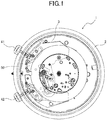
Fig. 1] Fig. 1 is a partially transparent view illustrating one embodiment of an electronic timepiece according to the present disclosure, and representing a movement illustrated by a solid line, which is seen from a back cover side by virtually passing through a case illustrated by a two-dot chain line. - [
Fig. 2] Fig. 2 is a plan view illustrating arrangement of a stepping motor and a magnetic shielding plate in the movement illustrated inFig. 1 . - [
Fig. 3] Fig. 3 is a schematic view illustrating a slit having a longer side in a specific direction. - [
Fig. 4] Fig. 4 is a schematic view illustrating a plurality of circular holes which play the same role as the slit inFig. 3 and are arranged in the specific direction. - [
Fig. 5] Fig. 5 is a plan view illustrating arrangement of a stepping motor and a magnetic shielding plate in a movement of Modified Example 1. - [
Fig. 6] Fig. 6 is a plan view illustrating arrangement of a stepping motor and a magnetic shielding plate in a movement of Modified Example 2. - [
Fig. 7] Fig. 7 is a schematic view illustrating a variation (Modified Example 3) of arrangement of two stepping motors and formation of slits in a magnetic shielding plate when a movement of an electronic timepiece according to another embodiment of the present disclosure includes the two stepping motors. - [
Fig. 8] Fig. 8 is a schematic view illustrating a variation (Modified Example 4) of arrangement of two stepping motors and formation of slits in a magnetic shielding plate when a movement of an electronic timepiece according to another embodiment of the present disclosure includes the two stepping motors. - [
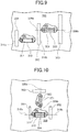
Fig. 9] Fig. 9 is a schematic view illustrating a variation (Modified Example 5) of arrangement of two stepping motors and formation of slits in a magnetic shielding plate when a movement of an electronic timepiece according to another embodiment of the present disclosure includes the two stepping motors. - [
Fig. 10] Fig. 10 is a schematic view illustrating a variation (Modified Example 6) of arrangement of two stepping motors and formation of slits in a magnetic shielding plate when a movement of an electronic timepiece according to another embodiment of the present disclosure includes the two stepping motors. - [
Fig. 11] Fig. 11 is a schematic view illustrating a variation (Modified Example 7) of arrangement of a stepping motor and formation of slits in a magnetic shielding plate when a movement of the electronic timepiece according to another embodiment of the present disclosure includes two coils. - [
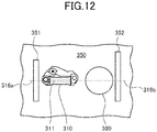
Fig. 12] Fig. 12 is a schematic view illustrating Modified Example in which a battery (one example of magnetic material) is arranged instead of the single stepping motor inFig. 7 . - Hereinafter, an embodiment of a movement of an electronic timepiece and an electronic timepiece according to the present disclosure will be described with reference to the drawings.
-
Fig. 1 is a partially transparent view illustrating an electronic timepiece 1 as one embodiment of the electronic timepiece according to the present disclosure, and representing amovement 3 illustrated by a solid line, which is seen from a back cover side virtually passing through acase 2 illustrated by a two-dot chain line.Fig. 1 shows, in an upper side thereof, a 12 o'clock direction and, in a left side thereof, a 3 o'clock direction.Fig. 2 is a plan view illustrating the arrangement of astepping motor 10 and amagnetic shielding plate 50 in themovement 3 illustrated inFig. 1 . - In the electronic timepiece 1, the
movement 3 is housed inside themetal case 2. The electronic timepiece 1 is a radio controlled timepiece including an operation that receives radio wave, and automatically corrects a pointer for indicating a time with themovement 3 based on the received radio wave. The electronic timepiece 1 includes a solar cell panel and a secondary battery, generates electricity with the solar cell panel, and drives themovement 3 by electric power stored in the secondary battery. - The
movement 3 is one embodiment of a movement of an electronic timepiece according to the present disclosure. Themovement 3 includes thestepping motor 10, push buttons (PB) 41, 42, PB clicksprings 31, 32 (refer toFig. 2 ), and themagnetic shielding plate 50. The steppingmotor 10 drives a train wheel for rotating a pointer for displaying a time with supplied electric power stored in the secondary battery. A user pushes the push buttons (PB) 41, 42 for switching various operations of the electronic timepiece 1 and for inputting a specific operation. The PB clicksprings 31, 32 (refer toFig. 2 ) produce a click feeling as a reaction force of a pushed operation. - In addition to the above-described configurations, the
movement 3 includes a mechanism of manually correcting an indicated position of a pointer, another mechanism, and another component. However, they are not necessary for describing the electronic timepiece 1 of the present embodiment, and the description for them are thus omitted. - As illustrated in
Fig. 2 , thestepping motor 10 includes acoil 11,stators 12, and arotor 13. Thecoil 11 includes a linearly extendingcoil winding core 11a and aconductive wire 11b. Theconductive wire 11b is spirally wound around thecoil winding core 11a. Thestators 12 are connected to afirst end portion 11c of thecoil winding core 11a and asecond end portion 11d of thecoil winding core 11a. Thestators 12 also have an end portion opposite to the end portion connected to thefirst end portion 11c and an end portion opposite to the end portion connected to thesecond end portion 11d, respectively. These end portions of thestators 12 face to each other across therotor 13. - As illustrated in
Fig. 2 , themagnetic shielding plate 50 is arranged to cover theentire stepping motor 10 except for thecoil 11 in a plan view. Thecoil 11 of thestepping motor 10 has a thickness larger than those of thestators 12 and therotor 13. Themagnetic shielding plate 50 therefore includes anopening portion 53 through which thecoil 11 passes in the thickness direction, so as to prevent interference with thecoil 11. - In addition, although the
magnetic shielding plate 50 may cover thecoil 11, it is not necessary to cover theentire stepping motor 10. More specifically, themagnetic shielding plate 50 should cover at least therotor 13, a portion over anextended line 16a in an extending direction of thecoil winding core 11a from thefirst end portion 11c, and a portion over anextended line 16b in an extending direction of thecoil winding core 11a from thesecond end portion 11d. - As the
magnetic shielding plate 50 is to prevent or control magnetism, which is generated and flown inside the electronic timepiece 1 due to the external magnetic field of the electronic timepiece 1, from flowing in the steppingmotor 10, themagnetic shielding plate 50 is originally required to have a size that covers only the steppingmotor 10. On the other hand, themagnetic shielding plate 50 of the present embodiment has a size larger than that of thestepping motor 10. Apart of the magnetic shielding plate 50 (that is not required to serve as magnetic shielding plate 50) except for a part of themagnetic shielding plate 50 that covers thestepping motor 10 serves as a bridge that supports, for example, the train wheel and the PB clicksprings - Although the
movement 3 of the present embodiment includes only thesingle stepping motor 10, themovement 3 may include two ormore stepping motors 10. Even when themovement 3 includes the two ormore stepping motors 10, the singlemagnetic shielding plate 50 can cover the two ormore stepping motors 10. Accordingly, such a configuration having the singlemagnetic shielding plate 50 can reduce the costs to be lower than that of a configuration having a plurality of small magnetic shielding plates to be provided for a plurality of stepping motors, respectively. - The
magnetic shielding plate 50 also supports the PB click springs 31, 32, for example. The configuration having such amagnetic shielding plate 50 can reduce the costs to be lower than that of a configuration having a bridge that supports the PB click springs 31, 32, in addition to themagnetic shielding plate 50. -
Slits extended lines magnetic shielding plate 50 that cover theextended lines coil winding core 11a from both of theend portions coil winding core 11a. Theseslits extended lines coil 11 in which theconductive wire 11b is wound around thecoil winding core 11a. Theseslits extended lines extended lines coil winding core 11a)) larger (wider) than the diameter of thecoil winding core 11a. - According to the
movement 3 and the electronic timepiece 1 configured as described above, the direction of the external magnetic field that may affect the operation of the steppingmotor 10 corresponds to the longitudinal direction of thecoil 11 of the steppingmotor 10. As illustrated inFig. 2 , when themagnetic shielding plate 50 in the present embodiment is exposed by the external magnetic field which causes a magnetic flow T1 directed toward thecoil 11 from the direction of theextended line 16a of thecoil 11, the magnetic flow T1 in themagnetic shielding plate 50 is blocked by theslit 51 formed near thecoil 11 from flowing in thecoil 11. - The magnetic flow T1 is then changed to flows T1a, T1b which are not directed toward the
coil 11, namely, which are directed along an end portion of themagnetic shielding plate 50 outside theslit 51. Namely, theslit 51 is one example of a magnetic flow changing portion that changes the magnetic flow T1 which is directed toward thecoil 11 to the magnetic flow which is not directed toward thecoil 11. - As illustrated in
Fig. 2 , when themagnetic shielding plate 50 in the present embodiment is exposed by the external magnetic field which causes a magnetic flow T2 directed toward thecoil 11 from the direction of theextended line 16b of thecoil 11, the magnetic flow T2 in themagnetic shielding plate 50 is blocked by theslit 52 formed near thecoil 11 from flowing in thecoil 11. - The magnetic flow T2 is then changed to flows T2a, T2b which are not directed toward the
coil 11, namely, which are directed along the end portion of themagnetic shielding plate 50 outside theslit 52. Namely, theslit 52 is one example of the magnetic flow changing portion that changes the magnetic flow T2 which is directed toward thecoil 11 to the magnetic flow which is not directed toward thecoil 11. - As described above, according to the
movement 3 of the electronic timepiece 1 and the electronic timepiece 1 of the present embodiment, the magnetic flows T1, T2 in the longitudinal direction of thecoil 11 by which the steppingmotor 10 is easily most affected are prevented or controlled from flowing in the steppingmotor 10 covered by themagnetic shielding plate 50. It may therefore become difficult for the steppingmotor 10 covered by themagnetic shielding plate 50 to be affected by the magnetic flows T1, T2. - The magnetic flow T1a having a direction changed by the
slit 51 is directed toward a supportingportion 56a that supports thePB click spring 31 as one example of a component which does not require a magnetic shielding performance. The magnetic flow T1b having a direction changed by theslit 51 is also directed to a supportingportion 56b that supports a component except for the steppingmotor 10. Accordingly, themovement 3 and the electronic timepiece 1 of the present embodiment can effectively use portions that receive the magnetic flows T1a, T1b (magnetic flow bypass portion that bypasses magnetic flow T1) as the supportingportions - Similarly, the magnetic flow T2a having a direction changed by the
slit 52 is directed toward a supportingportion 56c that supports thePB click spring 32 as one example of a component which does not require the magnetic shielding performance. The magnetic flow T2b having a direction changed by theslit 52 is directed to a supportingportion 56d that supports a component except for the steppingmotor 10. Accordingly, themovement 3 and the electronic timepiece 1 of the present embodiment can effectively use portions that receive the magnetic flows T2a, T2b (magnetic flow bypass portion that bypasses magnetic flow T2) as the supportingportions - In the
movement 3 of the electronic timepiece 1 and the electronic timepiece 1 of the present embodiment, theslits magnetic shielding plate 50 in the thickness direction are provided as the magnetic flow changing portions in the present disclosure. However, the magnetic flow changing portion is not limited to a slit having a longer side in a specific direction. More specifically, the magnetic flow changing portion in the present disclosure may be a hole penetrating through themagnetic shielding plate 50 in the thickness direction or may be a cutout formed in an end portion of themagnetic shielding plate 50. The hole may have a circular shape, a rectangular shape, or another shape. - As illustrated in
Fig. 3 , theslits Fig. 4 , for example, a plurality ofcircular holes 51a may be formed instead of theelongated slits circular holes 51a are arranged in a line atintervals 54, and each of thecircular holes 51a has a diameter D (< L) having a length in the longitudinal direction smaller than that of each of theslits - By forming the magnetic flow changing portion with a plurality of
holes 51a instead of the singlelong slit magnetic shielding plate 50 may be maintained stronger than that of themagnetic shielding plate 50 in which thesingle slit intervals 54 remain as themagnetic shielding plate 50. In addition, the number ofcircular holes 51 to be arranged may be the number corresponding to the length L of thesingle slit - The
slits slits slits circular holes 51a, it may not be necessary for a plurality ofholes 51a to have the same diameter D. Moreover, theslits - The magnetic flow changing portion in the present disclosure is not limited as long as it is configured to change the magnetic flows T1, T2 which are directed toward the
coil 11 to the magnetic flows T1a, T1b, T2a, T2b which are not directed toward thecoil 11. Namely, the magnetic flow changing portion in the present disclosure is not limited as long as it is configured such that the magnetism easily flows in the directions different from the direction of thecoil 11 rather than the direction of thecoil 11. Accordingly, instead of theslits magnetic shielding plate 50 in the thickness direction as the magnetic flow changing portion, a groove having a longer side in a specific direction may be provided. Such a groove has a thickness smaller than that of another portion. Instead of the hole that penetrates through themagnetic shielding plate 50 in the thickness direction, a recess (concave portion) having a thickness smaller than that of another portion may be provided. - In the
movement 3 of the electronic timepiece 1 and the electronic timepiece 1 of the present embodiment, theslits end portions coil 11. It is necessary for theslits end portions coil 11. If the magnetic flow is fixed in one direction, theslits first end portion 11c of thecoil 11 or thesecond end portion 11d of thecoil 11 such that the slits are suitable only for the magnetism in the one direction of the flow. - When the electronic timepiece 1 is a watch to be carried to various places, it is, however, rare that such a watch is used in an environment where the magnetic flow is fixed in one direction. Accordingly, it is practically preferable for the
slits magnetic shielding plate 50 that correspond to the outsides of both of theend portions coil 11. - The
slits stators 12 to surround a part of thestators 12 from the outside. Such slits can effectively eliminate the influence of the external magnetic field to thestators 12. However, the magnetic flow changing portion in the present disclosure may not be limited to a shape along the external outline of the stators. - In the present embodiment, the length of the
slits coil 11, and the width of theslits coil winding core 11a. However, in the present disclosure, the length of the magnetic flow changing portion in the longitudinal direction may be smaller than the diameter of thecoil 11, and the width of the magnetic flow changing portion may be smaller than the diameter of thecoil winding core 11a. - The supporting
portions 56a, ..., 56d of themagnetic shielding plate 50 are not limited to the portions that support the PB click springs 31, 32, and may be portions that support other components of themovement 3. The supportingportions 56a, ..., 56b are not limited to the portions that support components, and may serve as portions that receive the magnetic flows T1a, T1b, T2a, T2b whose directions are changed by theslits - In addition, when the movement has a plurality of stepping motors, a portion that covers the stepping motor having a lowest frequency of use may be used as a portion in which the magnetism flows as the supporting portion.
-
Fig. 5 is a plan view illustrating arrangement of steppingmotors movement 103 of anelectronic timepiece 101 and amagnetic shielding plate 150 as another embodiment (Modified Example 1) of the present disclosure. The illustratedelectronic timepiece 101 has the same basic configuration as the electronic timepiece 1 illustrated inFig. 1 , and only differs from the electronic timepiece 1 illustrated inFig. 1 in themovement 103. - Different from the
movement 3, themovement 103 includes the two steppingmotors magnetic shielding plate 150 covers the two steppingmotors - In addition to a
hole 153 that avoids acoil 111 of the steppingmotor 110 and ahole 156 that avoids acoil 121 of the steppingmotor 120, holes 151, 152 intersecting withextended lines magnetic shielding plate 150, which cover theextended lines coil winding core 111a in the longitudinal direction from bothend portions coil winding core 111a of thecoil 111. - Similarly, holes 154, 155 intersecting with
extended lines magnetic shielding plate 150, which cover theextended lines coil winding core 121a in the longitudinal direction from bothend portions coil winding core 121a of thecoil 121. - When the
movement 103 and theelectronic timepiece 101 configured above are exposed by an external magnetic field that generates magnetic flows T1, T2 toward thecoil 111 from the directions of theextended lines coil 111, the magnetic flows T1, T2 in themagnetic shielding plate 150 are blocked by therectangular hole 151 and thecircular hole 152 formed near thecoil 111 from flowing in thecoil 111, and are changed to flows T1a, T1b, T2a, T2b which are not directed toward thecoil 111. - The
magnetic shielding plate 150 includes supportingportions motors coil 111. That is, themagnetic shielding plate 150 effectively uses the portions receiving the magnetic flows T1a, T1b, T2a, T2b as the supportingportions - Similarly, when the
movement 103 and theelectronic timepiece 101 are exposed by an external magnetic field that generates magnetic flows T3, T4 which are directed toward thecoil 121 from the directions of theextended lines coil 121, the magnetic flows T3, T4 in themagnetic shielding plate 150 are blocked by therectangular holes coil 121 from flowing in thecoil 121, and are changed to flows T3a, T3b, T4a, T4b which are not directed toward thecoil 121. - The
magnetic shielding plate 150 includes supportingportions motors - As described above, according to the
movement 103 of theelectronic timepiece 101 and theelectronic timepiece 101, the magnetic flows T1, T2 in the longitudinal direction of thecoil 111 by which the steppingmotor 110 is easily affected can be prevented or controlled from flowing in the steppingmotor 110 covered by themagnetic shielding plate 150, and the magnetic flows T3, T4 in the longitudinal direction of thecoil 121 by which the steppingmotor 120 is easily affected can be prevented or controlled from flowing in the steppingmotor 120 covered by themagnetic shielding plate 150. It becomes difficult for the steppingmotor 110 covered by themagnetic shielding plate 150 to be affected by the magnetic flows T1, T2, and it becomes also difficult for the steppingmotor 120 covered by themagnetic shielding plate 150 to be affected by the magnetic flows T3, T4. - According to the
movement 103 of theelectronic timepiece 101 and theelectronic timepiece 101, the singlemagnetic shielding plate 150 covers the two steppingmotors - Moreover, as the
holes magnetic shielding plate 150 in accordance with the steppingmotors motors - In addition, in the
movement 103, another component 104 (for example, conductive spring for alarm) arranged in a range corresponding to a range inside the external outline of themagnetic shielding plate 150 may be arranged in thehole 152 as the magnetic flow changing portion. Such a configuration which arranges anothercomponent 104 in thehole 152 allows a space to be used more effectively than a configuration that uses thehole 152 only as the magnetic flow changing portion. -
Fig. 6 is a plan view illustrating arrangement of a steppingmotor 210 and amagnetic shielding plate 250 in amovement 203 of anelectronic timepiece 201 as another embodiment (Modified Example 2) of the present disclosure. The illustratedelectronic timepiece 201 includes the same basic configuration as the electronic timepiece 1 illustrated inFig. 1 , and only differs from the electronic timepiece 1 illustrated inFig. 1 in themovement 203. - Different from the
movement 3, in themovement 203, amagnetic shielding plate 250 that covers the steppingmotor 210 includes a ring likemagnetic shielding plate 250a (hereinafter, ring magnetic shielding plate) that covers an outer circumference portion of themovement 203 and a plate likemagnetic shielding plate 250b (hereinafter, "plate magnetic shielding plate") that covers theentire movement 203 including the ringmagnetic shielding plate 250a. - The ring
magnetic shielding plate 250a is formed along an external form of themovement 203. The ringmagnetic shielding plate 250a includes, in a part thereof (for example, 3 o'clock position of timepiece 201), a cutout. A windingstem 205 is provided at a position (portion overlapped with cutout 250a1 in plan view) corresponding to the cutout portion (cutout) 250a1. The windingstem 205 extends from the outside of the ringmagnetic shielding plate 250a in a direction toward a center C of the movement 203 (center of ring of ringmagnetic shielding plate 250a), and is inserted through the inside of the ringmagnetic shielding plate 250a. - The ring
magnetic shielding plate 250a does not overlap with the steppingmotor 210 in the thickness direction, but is arranged to surround the steppingmotor 210 from the outside in the radial direction of themovement 203, and shields the magnetic flow to themovement 203 from the external magnetic field of themovement 203. The ringmagnetic shielding plate 250a is arranged outside the steppingmotor 210 and outside twoslits 251, 252 formed in the after-described platemagnetic shielding plate 250b. On the other hand, the platemagnetic shielding plate 250b overlaps with the steppingmotor 210 in the thickness direction to cover the steppingmotor 210. The platemagnetic shielding plate 250b overlaps with the windingstem 205 in the thickness direction to cover the windingstem 205. - Although the plate
magnetic shielding plate 250b is originally a bridge that supports a film solar cell disposed in a top surface of the platemagnetic shielding plate 250b, this bridge also serves as a magnetic shielding plate. Theslits 251, 252 intersecting withextended lines magnetic shielding plate 250b. These portions cover theextended lines coil winding core 211a from bothend portions coil winding core 211a of acoil 211 of the steppingmotor 210. The ringmagnetic shielding plate 250a and the platemagnetic shielding plate 250b are arranged to sandwich a not shown main plate in the thickness direction. In addition, the ringmagnetic shielding plate 250a may contact the platemagnetic shielding plate 250b. - When the
movement 203 and theelectronic timepiece 201 configured as described above are exposed by the external magnetic field that generates magnetic flows T1, T2 toward thecoil 211 from the directions of theextended lines coil 211, the magnetic flows T1, T2 in the platemagnetic shielding plate 250b are blocked by theslits 251, 252 formed near thecoil 211 from flowing in thecoil 211, and are changed to flows T1a, T1b, T2a, T2b which are not directed toward thecoil 211. - Although the plate
magnetic shielding plate 250b includes supportingportions motor 210 as portions that receive the flows T1a, T1b, T2a, T2b which are not directed toward thecoil 211, these portions that receive the magnetic flows T1a, T1b, T2a, T2b are effectively used as the supportingportions - As described above, according to the
movement 203 of theelectronic timepiece 201 and theelectronic timepiece 201, the magnetic flows T1, T2 in the longitudinal direction of thecoil 211 by which the steppingmotors 210 are easily most affected are prevented or controlled from flowing in the steppingmotor 210 covered by the platemagnetic shielding plate 250b. It becomes difficult for the steppingmotor 210 covered by the platemagnetic shielding plate 250b to be affected by the magnetic flows T1, T2. - The
electronic timepiece 201 includes a configuration in which the steppingmotor 210 is arranged such that theextended lines coil winding core 211a become parallel or substantially parallel (hereinafter, simply substantially parallel) to the direction of the cutout 250a1 (direction connecting cutout 250a1 and center C of ring of ringmagnetic shielding plate 250a) of the ringmagnetic shielding plate 250a including, in a part thereof in the circumference direction, the cutout 250a1 through which the windingstem 205 is inserted. As described above, by disposing the steppingmotor 210 such that theextended lines coil winding core 211a become substantially parallel to the direction of the cutout 250a1 of the ringmagnetic shielding plate 250a, the magnetic shielding performance with the ringmagnetic shielding plate 250a and the platemagnetic shielding plate 250b is further improved with respect to the steppingmotor 210. - Namely, as illustrated in
Fig. 6 , the magnetic flow T1 substantially parallel to thecoil winding core 211a generated by the external magnetic field flows in the ringmagnetic shielding plate 250a in addition to the platemagnetic shielding plate 250b. More specifically, a part of the magnetic flow T1 is guided inside the ringmagnetic shielding plate 250a from each of end portions 250a2, 250a3 of the ringmagnetic shielding plate 250a, that face each other via the cutout 250a1. A magnetic flow T11a guided inside the ringmagnetic shielding plate 250a from the end portion 250a2 flows inside the ringmagnetic shielding plate 250a in the clockwise direction, and a magnetic flow T11b guided inside the ringmagnetic shielding plate 250a from the end portion 250a3 flows inside the ringmagnetic shielding plate 250a in the counterclockwise direction. - A part of the magnetic flow T1 substantially parallel to the
coil winding core 211a, which is guided to the platemagnetic shielding plate 250b flows away from thecoil winding core 211a by theslits 251, 252, and a part of the magnetic flow T1 which is not guided to the platemagnetic shielding plate 250b is guided to the ringmagnetic shielding plate 250a, and also flows away from thecoil winding core 211a. According to themovement 203 of theelectronic timepiece 201 and theelectronic timepiece 201, the magnetic shielding performance to the steppingmotor 210 can be further improved with respect to the magnetic flow T1 substantially parallel to thecoil winding core 211a. - When the stepping
motor 210 is arranged such that the direction of the cutout 250a1 of the ringmagnetic shielding plate 250a becomes substantially parallel to theextended lines coil winding core 211a (inFig. 6 , when cutout 250a1 of ringmagnetic shielding plate 250a is formed in 12 o'clock position (upper side of figure) or 6 o'clock position (lower side of figure)), a part of the magnetic flow T1 is guided inside the ringmagnetic shielding plate 250a, and becomes the flow T11a in the clockwise direction and the flow T11b in the counterclockwise direction inside the ringmagnetic shielding plate 250a. - However, when the cutout 250a1 is formed in the 12 o'clock position, the magnetic flow T11a in the clockwise direction is blocked by the cutout 250a1, and flows from the cutout 250a1 to the plate
magnetic shielding plate 250b to be the magnetic flow toward thecoil winding core 211a which may affect thecoil winding core 211a. When the cutout 250a1 is formed in the 6 o'clock position, the magnetic flow T11b in the counterclockwise direction is blocked by the cutout 250a1, and flows from the cutout 250a1 in the platemagnetic shielding plate 250b to be the magnetic flow toward thecoil winding core 211a, which may affect thecoil winding core 211a. In addition, the magnetic flow T2 whose direction is opposite to that of the magnetic flow T1 is also blocked, and flows similar to the above magnetic flow T1. - As described in details, by disposing the stepping
motor 210 such that theextended lines coil winding core 211a becomes substantially parallel to the direction of the cutout 250a1 of the ringmagnetic shielding plate 250a, the magnetic shielding performance to the steppingmotor 210 by the ringmagnetic shielding plate 250a and the platemagnetic shielding plate 250b is further improved to be better than that when the steppingmotor 210 is arranged such that theextended lines coil winding core 211a do not become substantially parallel to the direction of the cutout 250a1 of the ringmagnetic shielding plate 250a (for example, steppingmotor 210 is arranged such thatextended lines coil winding core 211a become substantially orthogonal to direction of cutout 250a1 of ringmagnetic shielding plate 250a). - According to the electronic timepiece and the movement of the present disclosure, the stepping motor is not limited to be arranged such that the extended lines of the coil winding core become parallel to the direction of the cutout of the ring magnetic shielding plate as described above.
-
Figs. 7, 8 ,9, 10 ,11 are schematic views illustrating variations (Modified Examples 3 to 7) of arrangement of two steppingmotors slits magnetic shielding plate 350 when the movement of the electronic timepiece as another embodiment of the present disclosure includes the two steppingmotors - When the
coils motors Figs. 7, 8 ,9 ), theslits magnetic shielding plate 350 may be shared by the twocoils Figs. 7, 8 , or theslit 352 between the twocoils Fig. 9 . - More specifically, as illustrated in
Figs. 7, 8 , theslit 351 is formed to intersect with anextended line 316a of thecoil 311 of the steppingmotor 310 in the longitudinal direction and anextended line 326a of thecoil 321 of the steppingmotor 320 in the longitudinal direction while theslit 352 is formed to intersect with anextended line 316b of thecoil 311 of the steppingmotor 310 in the longitudinal direction and anextended line 326b of thecoil 321 of the steppingmotor 320 in the longitudinal direction. - As illustrated in
Fig. 9 , theslit 351 is formed to intersect with theextended line 316a of thecoil 311 of the steppingmotor 310 in the longitudinal direction, theslit 352 is formed to intersect with theextended line 316b of thecoil 311 of the steppingmotor 310 in the longitudinal direction and theextended line 326a of thecoil 321 of the steppingmotor 320 in the longitudinal direction, and theslit 353 is formed to intersect with theextended line 326b of thecoil 321 of the steppingmotor 320 in the longitudinal direction. - On the other hand, when both of the
coils 311, 312 of the two steppingmotors Fig. 10 ), two slits are formed with respect to each of the steppingmotors slit 351 is formed to intersect with theextended line 316a of thecoil 311 of the steppingmotor 310 in the longitudinal direction, theslit 352 is formed to intersect with theextended line 316b of thecoil 311 of the steppingmotor 310 in the longitudinal direction, theslit 353 is formed to intersect with theextended line 326a of thecoil 321 of the steppingmotor 320 in the longitudinal direction, and aslit 354 is formed to intersect with theextended line 326b of thecoil 321 of the steppingmotor 320 in the longitudinal direction. - However, when the
extended line 326b of thecoil 321 of the steppingmotor 320 in the longitudinal direction is arranged to intersect with thecoil 311 of the steppingmotor 310, a hole through which thecoil 311 is inserted is formed in themagnetic shielding plate 350, and the hole can be therefore used as theslit 354. - As illustrated in
Fig. 11 , when the steppingmotor 310 includes twocoils slit 351 is formed to intersect with theextended line 316a of thecoil 311A in the longitudinal direction and theextended line 316c of thecoil 311B in the longitudinal direction, and theslit 352 is formed to interest with theextended line 316b of thecoil 311A in the longitudinal direction and anextended line 316d of thecoil 311B in the longitudinal direction. - When a magnetic member, in particular a large magnetic member such as a battery is arranged near the stepping motor, a magnetic flow changing portion (for example, slit) may be provided in a portion of the large magnetic member, which is opposite to a portion near the stepping motor. The magnetic flow changing portion can prevent the external magnetism to be guided by the large magnetic member, and thus prevent the external magnetism from flowing in the neighboring stepping motor.
- When a
battery 380 is arranged instead of the steppingmotor 320 with the configuration illustrated inFig. 7 (seeFig. 12 ), for example, theright slit 352 of thebattery 380 operates as the magnetic flow changing portion that prevents the external magnetism to be guided by thebattery 380. This configuration is an example in which thebattery 380 is arranged between the steppingmotor 320 and theslit 352. - The present application is based on and claims priority to Japanese Patent Application No.
2017-172946, filed on September 8, 2017
Claims (10)
- A movement of an electronic timepiece, comprising:a stepping motor including a rotor, a stator, and a coil in which a conductive wire is wound around a coil winding core; anda magnetic shielding plate that covers at least a part of the stepping motor, whereinthe magnetic shielding plate includes a magnetic flow changing portion that changes a magnetic flow which is directed toward the coil winding core to a magnetic flow which is not directed toward the coil winding core, andthe magnetic flow changing portion is formed in a portion of the magnetic shielding plate, which corresponds to each of extended lines from both end portions of the coil winding core, to intersect with the corresponding extended line.
- The movement of the electronic timepiece according to claim 1, wherein the magnetic flow changing portion extends to surround a part of the stator from an outside of the stator.
- The movement of the electronic timepiece according to claim 1 or 2, comprising a plurality of the stepping motors, wherein
the magnetic flow changing portion is provided in the magnetic shielding plate to correspond to each of the plurality of the stepping motors. - The movement of the electronic timepiece according to any one of claims 1 to 3, wherein the magnetic flow changing portion is a slit or a hole that penetrates through the magnetic shielding plate in a thickness direction, or a groove or a recess having a thickness thinner than that of another portion.
- The movement of the electronic timepiece according to claim 4, wherein
the magnetic flow changing portion is the slit or the hole, and
a component in a range corresponding to a range inside an external outline of the magnetic shielding plate is arranged in the slit or the hole. - The movement of the timepiece according to any one of claims 1 to 5, wherein
the magnetic shielding plate includes a supporting portion as a portion that supports another component, and
the magnetic flow changing portion changes a direction of the magnetic flow to a direction toward the supporting portion. - The movement of the electronic timepiece according to any one of claims 1 to 6, further comprising a ring like magnetic shielding plate that surrounds the stepping motor, wherein
the ring like magnetic shielding plate includes, in a part thereof in a circumference direction, a cutout, and
the stepping motor is arranged such that the extended line becomes substantially parallel to a direction connecting the cutout and a center of the ring like magnetic shielding plate. - The movement of the electronic timepiece according to claim 7, wherein the ring like magnetic shielding plate is arranged outside the two magnetic flow changing portions formed in the portions which correspond to the extended lines from the both end portions of the coil winding core, respectively.
- The movement of the electronic timepiece according to any one of claims 1 to 8, wherein a magnetic member is arranged between the stepping motor and the magnetic flow changing portion.
- An electronic timepiece in which the movement according to any one of claims 1 to 9 is housed inside a case.
Applications Claiming Priority (2)
| Application Number | Priority Date | Filing Date | Title |
|---|---|---|---|
| JP2017172946A JP6886902B2 (en) | 2017-09-08 | 2017-09-08 | Electronic clock movement and electronic clock |
| PCT/JP2018/029625 WO2019049587A1 (en) | 2017-09-08 | 2018-08-07 | Movement of electronic timepiece and electronic timepiece |
Publications (3)
| Publication Number | Publication Date |
|---|---|
| EP3677971A1 true EP3677971A1 (en) | 2020-07-08 |
| EP3677971A4 EP3677971A4 (en) | 2021-05-19 |
| EP3677971B1 EP3677971B1 (en) | 2025-10-29 |
Family
ID=65633878
Family Applications (1)
| Application Number | Title | Priority Date | Filing Date |
|---|---|---|---|
| EP18854970.3A Active EP3677971B1 (en) | 2017-09-08 | 2018-08-07 | Movement of electronic timepiece and electronic timepiece |
Country Status (5)
| Country | Link |
|---|---|
| US (1) | US20200301370A1 (en) |
| EP (1) | EP3677971B1 (en) |
| JP (1) | JP6886902B2 (en) |
| CN (1) | CN111033393B (en) |
| WO (1) | WO2019049587A1 (en) |
Families Citing this family (1)
| Publication number | Priority date | Publication date | Assignee | Title |
|---|---|---|---|---|
| JP7192750B2 (en) | 2019-11-26 | 2022-12-20 | カシオ計算機株式会社 | Pointer driving device, electronic clock, pointer driving method and program |
Family Cites Families (27)
| Publication number | Priority date | Publication date | Assignee | Title |
|---|---|---|---|---|
| JPS53102080A (en) * | 1977-02-17 | 1978-09-06 | Seiko Epson Corp | Magnetisum resistant structure of thin type crystal watch |
| JPS5510532A (en) * | 1978-07-08 | 1980-01-25 | Citizen Watch Co Ltd | Antimagnetic structure for crystal watch |
| EP0060814B1 (en) * | 1981-03-17 | 1986-08-27 | Consortium For World Trade Establishment | Apparatus for indicating the direction of mecca |
| JPS58112991U (en) * | 1982-01-28 | 1983-08-02 | セイコーエプソン株式会社 | Anti-magnetic structure of the watch |
| CN1007642B (en) * | 1986-08-06 | 1990-04-18 | 唐平科 | Rectangular vane-type vertical shaft wind mill |
| CH687288B5 (en) * | 1994-11-21 | 1997-05-15 | Asulab Sa | Watch comprising a detection device of the northbound earth magnetic. |
| CH691238A5 (en) * | 1996-04-17 | 2001-05-31 | Mondaine Watch Ltd | Generator an electronic watch movements. |
| US5930070A (en) * | 1996-06-27 | 1999-07-27 | Matsushita Electric Industrial Co., Ltd. | Tape loading apparatus for loading a magnetic tape in a magnetic recording and reproducing system |
| EP1024345B1 (en) * | 1998-06-22 | 2005-12-28 | Citizen Watch Co. Ltd. | Electronic apparatus with azimuth meter and azimuth measuring method in this electronic apparatus |
| WO2000016171A1 (en) * | 1998-09-10 | 2000-03-23 | Seiko Epson Corporation | Clocking device |
| GB2390414B (en) * | 2002-05-31 | 2005-03-30 | Camcon Ltd | Electromagnetic actuator and integrated actuator and fluid flow control valve |
| JP3654087B2 (en) * | 1999-10-12 | 2005-06-02 | セイコーエプソン株式会社 | Electronically controlled mechanical clock |
| JP2004212083A (en) * | 2002-12-27 | 2004-07-29 | Citizen Watch Co Ltd | Case structure of radio controlled watch |
| US6992481B2 (en) * | 2003-05-29 | 2006-01-31 | Timex Group B. V. | Method for compensating for predictable generated signals in an electronic device |
| JP4100409B2 (en) * | 2005-04-01 | 2008-06-11 | オムロン株式会社 | Operation input device and electronic apparatus using the same |
| JP2006343240A (en) * | 2005-06-09 | 2006-12-21 | Citizen Watch Co Ltd | Timepiece movement and timepiece |
| WO2008108394A1 (en) * | 2007-03-05 | 2008-09-12 | Citizen Holdings Co., Ltd. | Radio wave correction clock and its assembling method |
| CN101090022B (en) * | 2007-04-29 | 2011-11-23 | 沈阳工业大学 | A strong magnetic field permanent magnet mechanism to avoid abnormal magnetization |
| JP5118429B2 (en) * | 2007-09-21 | 2013-01-16 | シチズン時計株式会社 | Radio correction clock |
| JP5587808B2 (en) * | 2011-02-07 | 2014-09-10 | シチズンホールディングス株式会社 | Radio correction clock |
| US9519273B2 (en) * | 2014-03-06 | 2016-12-13 | Seiko Epson Corporation | Electronic timepiece and movement |
| JP6473632B2 (en) * | 2015-02-16 | 2019-02-20 | シチズン時計株式会社 | Electronic watch movement and electronic watch |
| JP2017026461A (en) * | 2015-07-22 | 2017-02-02 | セイコーエプソン株式会社 | Electronic clock |
| JP6724315B2 (en) * | 2015-09-07 | 2020-07-15 | カシオ計算機株式会社 | Electronic clock |
| JP6993079B2 (en) * | 2015-10-20 | 2022-01-20 | セイコーインスツル株式会社 | Manufacturing method of stepping motor |
| JP6593228B2 (en) * | 2016-03-09 | 2019-10-23 | セイコーエプソン株式会社 | Electronic clock |
| JP2017172946A (en) | 2016-03-25 | 2017-09-28 | 三菱重工サーマルシステムズ株式会社 | Air conditioning operation control device, air conditioning system, air conditioning operation control method, and program |
-
2017
- 2017-09-08 JP JP2017172946A patent/JP6886902B2/en active Active
-
2018
- 2018-08-07 CN CN201880050640.XA patent/CN111033393B/en active Active
- 2018-08-07 WO PCT/JP2018/029625 patent/WO2019049587A1/en not_active Ceased
- 2018-08-07 US US16/645,161 patent/US20200301370A1/en not_active Abandoned
- 2018-08-07 EP EP18854970.3A patent/EP3677971B1/en active Active
Also Published As
| Publication number | Publication date |
|---|---|
| WO2019049587A1 (en) | 2019-03-14 |
| CN111033393A (en) | 2020-04-17 |
| JP2019049436A (en) | 2019-03-28 |
| US20200301370A1 (en) | 2020-09-24 |
| EP3677971B1 (en) | 2025-10-29 |
| JP6886902B2 (en) | 2021-06-16 |
| CN111033393B (en) | 2022-01-07 |
| EP3677971A4 (en) | 2021-05-19 |
Similar Documents
| Publication | Publication Date | Title |
|---|---|---|
| JP3925552B2 (en) | Electronic watch with wireless communication function | |
| CN101599576B (en) | Antenna device and radio wave-using apparatus | |
| JP6901945B2 (en) | Portable radio clock | |
| US20170176945A1 (en) | Motor module for watches | |
| EP3376642A1 (en) | Motor | |
| EP3677971B1 (en) | Movement of electronic timepiece and electronic timepiece | |
| JP6724315B2 (en) | Electronic clock | |
| JP5118429B2 (en) | Radio correction clock | |
| JP2009079998A (en) | Radio-controlled timepiece | |
| JP3925558B2 (en) | Electronic watch with wireless communication function | |
| JP2021047144A (en) | Antenna built-in electronic watch | |
| JP2010066044A (en) | Radio wave receiving device | |
| JP2016151429A (en) | Movement of electronic timepiece and the electronic timepiece | |
| JP2004354366A5 (en) | ||
| JP2013195121A (en) | Movement for electronic wrist watch and electronic wrist watch | |
| JP2008249737A5 (en) | ||
| JP6973572B2 (en) | Electronic clock | |
| CN114639955B (en) | Arrangement structure of antenna and metal indicator component, and electronic clock | |
| JP3885827B2 (en) | Electronic watch with wireless communication function | |
| JP7424964B2 (en) | Arrangement structure of electronic clock and antenna and metal display member in electronic clock | |
| JP2005249737A5 (en) | ||
| JP6768260B2 (en) | Electronic clock movement and electronic clock | |
| JP7548051B2 (en) | Electronic clock | |
| JP2009294072A (en) | Electronic apparatus | |
| JP2022094609A (en) | Electronic timepiece and arrangement structure in electronic timepiece of antenna and metallic display member |
Legal Events
| Date | Code | Title | Description |
|---|---|---|---|
| STAA | Information on the status of an ep patent application or granted ep patent |
Free format text: STATUS: THE INTERNATIONAL PUBLICATION HAS BEEN MADE |
|
| PUAI | Public reference made under article 153(3) epc to a published international application that has entered the european phase |
Free format text: ORIGINAL CODE: 0009012 |
|
| STAA | Information on the status of an ep patent application or granted ep patent |
Free format text: STATUS: REQUEST FOR EXAMINATION WAS MADE |
|
| 17P | Request for examination filed |
Effective date: 20200331 |
|
| AK | Designated contracting states |
Kind code of ref document: A1 Designated state(s): AL AT BE BG CH CY CZ DE DK EE ES FI FR GB GR HR HU IE IS IT LI LT LU LV MC MK MT NL NO PL PT RO RS SE SI SK SM TR |
|
| AX | Request for extension of the european patent |
Extension state: BA ME |
|
| DAV | Request for validation of the european patent (deleted) | ||
| DAX | Request for extension of the european patent (deleted) | ||
| A4 | Supplementary search report drawn up and despatched |
Effective date: 20210416 |
|
| RIC1 | Information provided on ipc code assigned before grant |
Ipc: G04C 3/00 20060101AFI20210412BHEP Ipc: G04C 3/14 20060101ALI20210412BHEP |
|
| RIN1 | Information on inventor provided before grant (corrected) |
Inventor name: SAKATA, SHINNOSUKE Inventor name: NAKADAIRA, DAISUKE Inventor name: MATSUMURA, YOSHIKAZU Inventor name: MORITA, SHOICHIRO Inventor name: HIROTA, YUSUKE |
|
| STAA | Information on the status of an ep patent application or granted ep patent |
Free format text: STATUS: EXAMINATION IS IN PROGRESS |
|
| 17Q | First examination report despatched |
Effective date: 20230808 |
|
| REG | Reference to a national code |
Ref country code: DE Ref legal event code: R079 Free format text: PREVIOUS MAIN CLASS: G04C0003000000 Ipc: G04B0043000000 Ref country code: DE Ref legal event code: R079 Ref document number: 602018086785 Country of ref document: DE Free format text: PREVIOUS MAIN CLASS: G04C0003000000 Ipc: G04B0043000000 |
|
| GRAP | Despatch of communication of intention to grant a patent |
Free format text: ORIGINAL CODE: EPIDOSNIGR1 |
|
| STAA | Information on the status of an ep patent application or granted ep patent |
Free format text: STATUS: GRANT OF PATENT IS INTENDED |
|
| RIC1 | Information provided on ipc code assigned before grant |
Ipc: G04G 17/08 20060101ALI20250604BHEP Ipc: G04G 17/02 20060101ALI20250604BHEP Ipc: G04B 43/00 20060101AFI20250604BHEP |
|
| INTG | Intention to grant announced |
Effective date: 20250620 |
|
| GRAS | Grant fee paid |
Free format text: ORIGINAL CODE: EPIDOSNIGR3 |
|
| GRAA | (expected) grant |
Free format text: ORIGINAL CODE: 0009210 |
|
| STAA | Information on the status of an ep patent application or granted ep patent |
Free format text: STATUS: THE PATENT HAS BEEN GRANTED |
|
| AK | Designated contracting states |
Kind code of ref document: B1 Designated state(s): AL AT BE BG CH CY CZ DE DK EE ES FI FR GB GR HR HU IE IS IT LI LT LU LV MC MK MT NL NO PL PT RO RS SE SI SK SM TR |
|
| REG | Reference to a national code |
Ref country code: CH Ref legal event code: F10 Free format text: ST27 STATUS EVENT CODE: U-0-0-F10-F00 (AS PROVIDED BY THE NATIONAL OFFICE) Effective date: 20251029 Ref country code: GB Ref legal event code: FG4D |
|
| REG | Reference to a national code |
Ref country code: DE Ref legal event code: R096 Ref document number: 602018086785 Country of ref document: DE |
|
| REG | Reference to a national code |
Ref country code: IE Ref legal event code: FG4D |
|
| REG | Reference to a national code |
Ref country code: NL Ref legal event code: MP Effective date: 20251029 |
|
| PG25 | Lapsed in a contracting state [announced via postgrant information from national office to epo] |
Ref country code: ES Free format text: LAPSE BECAUSE OF FAILURE TO SUBMIT A TRANSLATION OF THE DESCRIPTION OR TO PAY THE FEE WITHIN THE PRESCRIBED TIME-LIMIT Effective date: 20251029 |
|
| REG | Reference to a national code |
Ref country code: LT Ref legal event code: MG9D |
|
| PG25 | Lapsed in a contracting state [announced via postgrant information from national office to epo] |
Ref country code: NO Free format text: LAPSE BECAUSE OF FAILURE TO SUBMIT A TRANSLATION OF THE DESCRIPTION OR TO PAY THE FEE WITHIN THE PRESCRIBED TIME-LIMIT Effective date: 20260129 |
|
| PG25 | Lapsed in a contracting state [announced via postgrant information from national office to epo] |
Ref country code: HR Free format text: LAPSE BECAUSE OF FAILURE TO SUBMIT A TRANSLATION OF THE DESCRIPTION OR TO PAY THE FEE WITHIN THE PRESCRIBED TIME-LIMIT Effective date: 20251029 Ref country code: FI Free format text: LAPSE BECAUSE OF FAILURE TO SUBMIT A TRANSLATION OF THE DESCRIPTION OR TO PAY THE FEE WITHIN THE PRESCRIBED TIME-LIMIT Effective date: 20251029 Ref country code: AT Free format text: LAPSE BECAUSE OF FAILURE TO SUBMIT A TRANSLATION OF THE DESCRIPTION OR TO PAY THE FEE WITHIN THE PRESCRIBED TIME-LIMIT Effective date: 20251029 |
|
| REG | Reference to a national code |
Ref country code: AT Ref legal event code: MK05 Ref document number: 1852254 Country of ref document: AT Kind code of ref document: T Effective date: 20251029 |
|
| PG25 | Lapsed in a contracting state [announced via postgrant information from national office to epo] |
Ref country code: NL Free format text: LAPSE BECAUSE OF FAILURE TO SUBMIT A TRANSLATION OF THE DESCRIPTION OR TO PAY THE FEE WITHIN THE PRESCRIBED TIME-LIMIT Effective date: 20251029 |
|
| PG25 | Lapsed in a contracting state [announced via postgrant information from national office to epo] |
Ref country code: RS Free format text: LAPSE BECAUSE OF FAILURE TO SUBMIT A TRANSLATION OF THE DESCRIPTION OR TO PAY THE FEE WITHIN THE PRESCRIBED TIME-LIMIT Effective date: 20260129 |
|
| PG25 | Lapsed in a contracting state [announced via postgrant information from national office to epo] |
Ref country code: IS Free format text: LAPSE BECAUSE OF FAILURE TO SUBMIT A TRANSLATION OF THE DESCRIPTION OR TO PAY THE FEE WITHIN THE PRESCRIBED TIME-LIMIT Effective date: 20260228 |
|
| PG25 | Lapsed in a contracting state [announced via postgrant information from national office to epo] |
Ref country code: PT Free format text: LAPSE BECAUSE OF FAILURE TO SUBMIT A TRANSLATION OF THE DESCRIPTION OR TO PAY THE FEE WITHIN THE PRESCRIBED TIME-LIMIT Effective date: 20260302 |
|
| PG25 | Lapsed in a contracting state [announced via postgrant information from national office to epo] |
Ref country code: PL Free format text: LAPSE BECAUSE OF FAILURE TO SUBMIT A TRANSLATION OF THE DESCRIPTION OR TO PAY THE FEE WITHIN THE PRESCRIBED TIME-LIMIT Effective date: 20251029 |
|
| PG25 | Lapsed in a contracting state [announced via postgrant information from national office to epo] |
Ref country code: LV Free format text: LAPSE BECAUSE OF FAILURE TO SUBMIT A TRANSLATION OF THE DESCRIPTION OR TO PAY THE FEE WITHIN THE PRESCRIBED TIME-LIMIT Effective date: 20251029 |
|
| PG25 | Lapsed in a contracting state [announced via postgrant information from national office to epo] |
Ref country code: BG Free format text: LAPSE BECAUSE OF FAILURE TO SUBMIT A TRANSLATION OF THE DESCRIPTION OR TO PAY THE FEE WITHIN THE PRESCRIBED TIME-LIMIT Effective date: 20251029 |
|
| PG25 | Lapsed in a contracting state [announced via postgrant information from national office to epo] |
Ref country code: LT Free format text: LAPSE BECAUSE OF FAILURE TO SUBMIT A TRANSLATION OF THE DESCRIPTION OR TO PAY THE FEE WITHIN THE PRESCRIBED TIME-LIMIT Effective date: 20251029 |
|
| PG25 | Lapsed in a contracting state [announced via postgrant information from national office to epo] |
Ref country code: SM Free format text: LAPSE BECAUSE OF FAILURE TO SUBMIT A TRANSLATION OF THE DESCRIPTION OR TO PAY THE FEE WITHIN THE PRESCRIBED TIME-LIMIT Effective date: 20251029 |
|
| PG25 | Lapsed in a contracting state [announced via postgrant information from national office to epo] |
Ref country code: DK Free format text: LAPSE BECAUSE OF FAILURE TO SUBMIT A TRANSLATION OF THE DESCRIPTION OR TO PAY THE FEE WITHIN THE PRESCRIBED TIME-LIMIT Effective date: 20251029 |
|
| PG25 | Lapsed in a contracting state [announced via postgrant information from national office to epo] |
Ref country code: IT Free format text: LAPSE BECAUSE OF FAILURE TO SUBMIT A TRANSLATION OF THE DESCRIPTION OR TO PAY THE FEE WITHIN THE PRESCRIBED TIME-LIMIT Effective date: 20251029 |
|
| PG25 | Lapsed in a contracting state [announced via postgrant information from national office to epo] |
Ref country code: EE Free format text: LAPSE BECAUSE OF FAILURE TO SUBMIT A TRANSLATION OF THE DESCRIPTION OR TO PAY THE FEE WITHIN THE PRESCRIBED TIME-LIMIT Effective date: 20251029 |
|
| PG25 | Lapsed in a contracting state [announced via postgrant information from national office to epo] |
Ref country code: CZ Free format text: LAPSE BECAUSE OF FAILURE TO SUBMIT A TRANSLATION OF THE DESCRIPTION OR TO PAY THE FEE WITHIN THE PRESCRIBED TIME-LIMIT Effective date: 20251029 |
|
| PG25 | Lapsed in a contracting state [announced via postgrant information from national office to epo] |
Ref country code: SK Free format text: LAPSE BECAUSE OF FAILURE TO SUBMIT A TRANSLATION OF THE DESCRIPTION OR TO PAY THE FEE WITHIN THE PRESCRIBED TIME-LIMIT Effective date: 20251029 |
|
| PG25 | Lapsed in a contracting state [announced via postgrant information from national office to epo] |
Ref country code: SE Free format text: LAPSE BECAUSE OF FAILURE TO SUBMIT A TRANSLATION OF THE DESCRIPTION OR TO PAY THE FEE WITHIN THE PRESCRIBED TIME-LIMIT Effective date: 20251029 |