EP3677947A1 - Headup display device - Google Patents
Headup display device Download PDFInfo
- Publication number
- EP3677947A1 EP3677947A1 EP18850074.8A EP18850074A EP3677947A1 EP 3677947 A1 EP3677947 A1 EP 3677947A1 EP 18850074 A EP18850074 A EP 18850074A EP 3677947 A1 EP3677947 A1 EP 3677947A1
- Authority
- EP
- European Patent Office
- Prior art keywords
- screen
- light
- orthogonal
- projection light
- diffusion
- Prior art date
- Legal status (The legal status is an assumption and is not a legal conclusion. Google has not performed a legal analysis and makes no representation as to the accuracy of the status listed.)
- Withdrawn
Links
Images

Classifications
-
- G—PHYSICS
- G02—OPTICS
- G02B—OPTICAL ELEMENTS, SYSTEMS OR APPARATUS
- G02B27/00—Optical systems or apparatus not provided for by any of the groups G02B1/00 - G02B26/00, G02B30/00
- G02B27/01—Head-up displays
- G02B27/0101—Head-up displays characterised by optical features
-
- G—PHYSICS
- G02—OPTICS
- G02B—OPTICAL ELEMENTS, SYSTEMS OR APPARATUS
- G02B3/00—Simple or compound lenses
- G02B3/0006—Arrays
- G02B3/0037—Arrays characterized by the distribution or form of lenses
-
- B—PERFORMING OPERATIONS; TRANSPORTING
- B60—VEHICLES IN GENERAL
- B60K—ARRANGEMENT OR MOUNTING OF PROPULSION UNITS OR OF TRANSMISSIONS IN VEHICLES; ARRANGEMENT OR MOUNTING OF PLURAL DIVERSE PRIME-MOVERS IN VEHICLES; AUXILIARY DRIVES FOR VEHICLES; INSTRUMENTATION OR DASHBOARDS FOR VEHICLES; ARRANGEMENTS IN CONNECTION WITH COOLING, AIR INTAKE, GAS EXHAUST OR FUEL SUPPLY OF PROPULSION UNITS IN VEHICLES
- B60K35/00—Instruments specially adapted for vehicles; Arrangement of instruments in or on vehicles
- B60K35/20—Output arrangements, i.e. from vehicle to user, associated with vehicle functions or specially adapted therefor
- B60K35/21—Output arrangements, i.e. from vehicle to user, associated with vehicle functions or specially adapted therefor using visual output, e.g. blinking lights or matrix displays
- B60K35/23—Head-up displays [HUD]
-
- G—PHYSICS
- G02—OPTICS
- G02B—OPTICAL ELEMENTS, SYSTEMS OR APPARATUS
- G02B27/00—Optical systems or apparatus not provided for by any of the groups G02B1/00 - G02B26/00, G02B30/00
- G02B27/01—Head-up displays
-
- G—PHYSICS
- G02—OPTICS
- G02B—OPTICAL ELEMENTS, SYSTEMS OR APPARATUS
- G02B3/00—Simple or compound lenses
-
- G—PHYSICS
- G02—OPTICS
- G02B—OPTICAL ELEMENTS, SYSTEMS OR APPARATUS
- G02B3/00—Simple or compound lenses
- G02B3/0006—Arrays
- G02B3/0037—Arrays characterized by the distribution or form of lenses
- G02B3/0056—Arrays characterized by the distribution or form of lenses arranged along two different directions in a plane, e.g. honeycomb arrangement of lenses
-
- G—PHYSICS
- G02—OPTICS
- G02B—OPTICAL ELEMENTS, SYSTEMS OR APPARATUS
- G02B5/00—Optical elements other than lenses
- G02B5/02—Diffusing elements; Afocal elements
-
- G—PHYSICS
- G02—OPTICS
- G02B—OPTICAL ELEMENTS, SYSTEMS OR APPARATUS
- G02B5/00—Optical elements other than lenses
- G02B5/02—Diffusing elements; Afocal elements
- G02B5/0205—Diffusing elements; Afocal elements characterised by the diffusing properties
- G02B5/0257—Diffusing elements; Afocal elements characterised by the diffusing properties creating an anisotropic diffusion characteristic, i.e. distributing output differently in two perpendicular axes
-
- G—PHYSICS
- G03—PHOTOGRAPHY; CINEMATOGRAPHY; ANALOGOUS TECHNIQUES USING WAVES OTHER THAN OPTICAL WAVES; ELECTROGRAPHY; HOLOGRAPHY
- G03B—APPARATUS OR ARRANGEMENTS FOR TAKING PHOTOGRAPHS OR FOR PROJECTING OR VIEWING THEM; APPARATUS OR ARRANGEMENTS EMPLOYING ANALOGOUS TECHNIQUES USING WAVES OTHER THAN OPTICAL WAVES; ACCESSORIES THEREFOR
- G03B21/00—Projectors or projection-type viewers; Accessories therefor
- G03B21/54—Accessories
- G03B21/56—Projection screens
- G03B21/60—Projection screens characterised by the nature of the surface
- G03B21/62—Translucent screens
- G03B21/625—Lenticular translucent screens
-
- G—PHYSICS
- G02—OPTICS
- G02B—OPTICAL ELEMENTS, SYSTEMS OR APPARATUS
- G02B27/00—Optical systems or apparatus not provided for by any of the groups G02B1/00 - G02B26/00, G02B30/00
- G02B27/01—Head-up displays
- G02B2027/0192—Supplementary details
- G02B2027/0198—System for aligning or maintaining alignment of an image in a predetermined direction
Definitions
- the present invention relates to a headup display device including a screen on which light is incident obliquely.
- headup display device for displaying, on a windshield of a vehicle or the like, various types of information and making the displayed information visible along with the surrounding background.
- An example of a conventional technology related to a headup display device includes a technology disclosed in Patent Document 1.
- a headup display device disclosed in Patent Document 1 includes a chassis housing a projector for projecting projection light, a first screen and a second screen on which reflected projection light forms an image, and a reflection system for reflecting diffusion light emitted from the first screen and the second screen.
- images displayed on the first screen and the second screen are visually recognized as a first virtual image and a second virtual image which are spaced apart from each other.
- Patent Document 1 Japanese Unexamined Patent Application Publication No. 2016-45252
- the first screen may be placed to be tilted with respect to an orthogonal plane orthogonal to the optical axis of the projection light. As a result, the first virtual image falling in a direction away from an occupant is visually recognized by the occupant.
- the projection light is incident on the first screen obliquely, a first diffusion light emitted from the first screen is emitted obliquely. That is, since the direction of the first diffusion light changes, the luminance of the first virtual image may be nonuniform.
- a headup display device providing no luminance variance of the virtual image even if the screen is placed obliquely.
- the present invention aims to provide a technology for suppressing luminance variance of diffusion light even if a screen is placed obliquely.
- a headup display device including a projector for projecting projection light, and a screen on which the projection light forms an image, the screen for diffusing the projection light, the screen being tilted with respect to an orthogonal plane orthogonal to an optical axis of the projection light, and including a diffusion unit for converting the projection light into diffusion light.
- a center line of a distribution angle of the diffusion light in a case where the screen and the optical axis of the projection light are orthogonal to each other is set to tilt in a direction identical to a tilt direction of the screen with respect to an orthogonal line orthogonal to an output surface of the screen.
- the diffusion unit is a microlens array
- the microlens array has a curvature increasing in a direction identical to the tilt direction of the screen.
- the center line of the distribution angle of the diffusion light in the case where the screen and the optical axis of the projection light are orthogonal to each other is tilted in the direction identical to the tilt direction of the screen with respect to the orthogonal line orthogonal to the output surface of the screen.
- the center line of the distribution angle of the diffusion light is also orthogonal to the output surface of the screen. If such a screen is tilted, the center line of the distribution angle is tilted in the opposite direction to its tilt direction.
- the center line of the distribution angle is set such that the center line is not orthogonal to the orthogonal plane and is tilted in the direction identical to the tilt direction of the screen. Accordingly, if the screen is tilted, the center line of the distribution angle is tilted in the opposite direction. Thus, the tilt of the center line of the distribution angle caused by the tilt of the screen is suppressed. As a result, luminance variance of the diffusion light is suppressed, and the luminance variance of the virtual image displayed in the occupant's eye box is also suppressed.
- a microlens array is employed for the diffusion unit to convert the projection light into diffusion light, that is, to emit homogenized and shaped projection light.
- the curvature of the microlens array increases in the direction identical to the tilt direction of the screen. Thus, it is possible to tilt the diffusion light in the direction identical to the tilt direction of the screen.
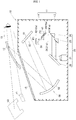
- Fig. 1 illustrates a headup display device 10 mounted on a vehicle, according to the present invention.
- the headup display device 10 includes, in a housing 11, a projection unit 20 for projecting light, a first screen 30 and a second screen 40 on which the light forms images, and a reflection unit 50 for reflecting the light transmitted through the first screen 30 and the second screen 40 toward a windshield 12.
- the housing 11 is made of a light shielding synthetic resin and has a box shape.
- the housing 11 includes a lower housing 13 and an upper housing 14 covering an upper opening of the lower housing 13.
- the upper housing 14 includes a transmission cover 15 for transmitting the light reflected from the reflection unit 50.
- the projection unit 20 includes a projector 21 fixed to the bottom surface of the lower housing 13, a projection mirror 22 for reflecting the light projected from the projector 21, and a first reflection mirror 23 and a second reflection mirror 24 for each reflecting the light reflected by the projection mirror 22.
- the projector 21 includes, for example, a light source for emitting light, a DMD (Digital MicroMirror Device) being a reflective display element for displaying an image, and a lens. Their detailed description is omitted.
- An LCOS registered trademark: Liquid Crystal On Silicon
- a TFT Thin Film Transistor liquid crystal panel being a transmissive display element may be used for the display element in the projector 21.
- the projection mirror 22, the first reflection mirror 23, and the second reflection mirror 24 are each formed, for example, by depositing a reflecting film on a surface of a synthetic resin base material.
- the reflection unit 50 includes a first reflection mirror 51 provided on the top plate of the upper housing 14 and a second reflection mirror 52 provided on a side surface of the lower housing 13.
- the first reflection mirror 51 is formed, for example, by depositing a reflecting film on a surface of a synthetic resin base material.
- the reflecting surface of the first reflection mirror 51 has a planar shape.
- the second reflection mirror 52 is formed, for example, by depositing a reflecting film on a surface of a synthetic resin base material.
- the reflecting surface of the second reflection mirror 52 has a concave shape.
- First projection light 31 and second projection light 41 which are projected from the projector 21 pass through the projection mirror 22, the first reflection mirror 23, and the second reflection mirror 24, and form images on the first screen 30 and the second screen 40, respectively.
- first image P1 is displayed on the first screen 30, the first screen 30 emits first diffusion light 32.
- second image P2 is displayed on the second screen 40, the second screen 40 emits second diffusion light 42.
- the first diffusion light 32 and the second diffusion light 42 are reflected toward the windshield 12 through the first reflection mirror 51 and the second reflection mirror 52.
- the first image P1 and the second image P2 are projected on the windshield 12.
- An occupant can visually recognize a first virtual image V1 which is an enlargement of the first image P1 and a second virtual image V2 which is an enlargement of the second image P2.
- Each of the first screen 30 and the second screen 40 is a transmissive screen composed of, for example, a holographic diffuser, a microlens array, a diffusion plate, and the like.
- the first screen 30 is orthogonal to an optical axis 31a of the first projection light 31.
- the second screen 40 is tilted in a clockwise direction C with respect to an orthogonal plane 43 orthogonal to an optical axis 41a of the second projection light 41.
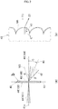
- Fig. 2(a) is referred to. Normally, if projection light 101 is incident on an incident surface 102 at a right angle, a center line 104 of a distribution angle ⁇ (a bisector of the distribution angle ⁇ ) of diffusion light 103 emitted is orthogonal to an output surface 105.
- a distribution angle ⁇ a bisector of the distribution angle ⁇
- a center line 45 of a distribution angle ⁇ is set such that the center line 45 is not orthogonal to an output surface 46 but is tilted in the clockwise direction C (the direction identical to the direction in which the second screen 40 is tilted (see Fig. 1 )) with respect to an orthogonal line 48 orthogonal to the output surface 46 if the second projection light 41 is incident on an incident surface 44 at a right angle.
- Fig. 2(b) illustrates an enlarged part of a main part of a microlens array 47 (diffusion unit 47) provided in the second screen 40.
- the microlens array 47 in which the shape of its surface is changed based on the shape of a microlens array 106 employed in a normal screen is employed.
- the microlens array 47 has a curvature (the reciprocal of a radius of curvature r) increasing in the clockwise direction C (the direction identical to the tilt direction of the second screen 40).
- the direction of light transmitted through the normal microlens array 106 is used as a reference as indicated by arrow (1)
- the direction of light transmitted through the microlens array 47 can be changed as indicated by arrow (2).
- the microlens array 47 may be provided on the incident surface 44 of the second screen 40.
- a screen 100 (for example, corresponding to the first screen 30) as a comparative embodiment according to a conventional art, if the projection light 101 is incident on the screen 100 at a right angle, the center line 104 of the distribution angle ⁇ of the diffusion light 103 is also orthogonal to the output surface 105 of the screen 100.
- the center line 45 of the distribution angle ⁇ of the second diffusion light 42 is set such that the center line 45 is not orthogonal to the output surface 46 but is tilted in the clockwise direction C with respect to the orthogonal line 48 if the second projection light 41 is incident on the second screen 40 at a right angle, that is, if the optical axis 41a and the incident surface 44 are orthogonal to each other.
- the center line 45 that is tilted in the clockwise direction C in advance is tilted in the counterclockwise direction A.
- the tilt direction (counterclockwise direction A) of the center line 45 caused by the tilt of the second screen 40 and the tilt direction (clockwise direction C) of the center line 45 caused by the microlens array are set to be opposed to each other, the tilt of the center line 45 is suppressed. As a result, it is possible to suppress the luminance of the second virtual image V2 from being nonuniform.
- a center line 45a of the distribution angle ⁇ of the second diffusion light 42 is set to be on the orthogonal line 48. That is, the direction of second diffusion light 42a is the same as that of a normal screen such as the first screen 30, and the luminance of the second diffusion light 42a is uniform. Accordingly, the luminance of the second virtual image V2 displayed within the range of the eye box 16 (see Fig. 1 ) is uniform (see Fig. 3(d) ).
- the headup display device 10 has been described as that used in a vehicle by way of example, but is applicable to other vehicles and is not limited to such types.
- the screen is not limited to the windshield, and may be a combiner supported by a casing.
- a diffraction grating may be employed for the diffusion unit instead of the microlens array. That is, the present invention is not limited to the embodiment as long as the operation and effect of the present invention are exhibited.
- Ahead-up display device is suitable to be mounted on a vehicle.
Landscapes
- Physics & Mathematics (AREA)
- General Physics & Mathematics (AREA)
- Optics & Photonics (AREA)
- Engineering & Computer Science (AREA)
- Chemical & Material Sciences (AREA)
- Combustion & Propulsion (AREA)
- Transportation (AREA)
- Mechanical Engineering (AREA)
- Instrument Panels (AREA)
- Optical Elements Other Than Lenses (AREA)
Abstract
Description
- The present invention relates to a headup display device including a screen on which light is incident obliquely.
- There is a so-called headup display device for displaying, on a windshield of a vehicle or the like, various types of information and making the displayed information visible along with the surrounding background. An example of a conventional technology related to a headup display device includes a technology disclosed in
Patent Document 1. - A headup display device disclosed in
Patent Document 1 includes a chassis housing a projector for projecting projection light, a first screen and a second screen on which reflected projection light forms an image, and a reflection system for reflecting diffusion light emitted from the first screen and the second screen. - When the diffusion light emitted from the headup display device is incident on a windshield, images displayed on the first screen and the second screen are visually recognized as a first virtual image and a second virtual image which are spaced apart from each other.
- Patent Document 1: Japanese Unexamined Patent Application Publication No.
2016-45252 - The first screen may be placed to be tilted with respect to an orthogonal plane orthogonal to the optical axis of the projection light. As a result, the first virtual image falling in a direction away from an occupant is visually recognized by the occupant.
- However, since the projection light is incident on the first screen obliquely, a first diffusion light emitted from the first screen is emitted obliquely. That is, since the direction of the first diffusion light changes, the luminance of the first virtual image may be nonuniform.
- To make the luminance uniform, it is conceivable to adjust the luminance of the projection light incident on the first screen in advance. However, such adjustment results in complicated control of the projection light in the projector. There is desirably a headup display device providing no luminance variance of the virtual image even if the screen is placed obliquely.
- The present invention aims to provide a technology for suppressing luminance variance of diffusion light even if a screen is placed obliquely.
- According to an invention set forth in
claim 1, provided is a headup display device including a projector for projecting projection light, and a screen on which the projection light forms an image, the screen for diffusing the projection light,
the screen being tilted with respect to an orthogonal plane orthogonal to an optical axis of the projection light, and including a diffusion unit for converting the projection light into diffusion light. - In the headup display device, a center line of a distribution angle of the diffusion light in a case where the screen and the optical axis of the projection light are orthogonal to each other is set to tilt in a direction identical to a tilt direction of the screen with respect to an orthogonal line orthogonal to an output surface of the screen.
- As defined in
claim 2, preferably, the diffusion unit is a microlens array, and the microlens array has a curvature increasing in a direction identical to the tilt direction of the screen. - In the invention according to
claim 1, the center line of the distribution angle of the diffusion light in the case where the screen and the optical axis of the projection light are orthogonal to each other is tilted in the direction identical to the tilt direction of the screen with respect to the orthogonal line orthogonal to the output surface of the screen. - Usually, if the projection light is incident on the screen at a right angle, the center line of the distribution angle of the diffusion light is also orthogonal to the output surface of the screen. If such a screen is tilted, the center line of the distribution angle is tilted in the opposite direction to its tilt direction.
- In the screen according to the present invention, the center line of the distribution angle is set such that the center line is not orthogonal to the orthogonal plane and is tilted in the direction identical to the tilt direction of the screen. Accordingly, if the screen is tilted, the center line of the distribution angle is tilted in the opposite direction. Thus, the tilt of the center line of the distribution angle caused by the tilt of the screen is suppressed. As a result, luminance variance of the diffusion light is suppressed, and the luminance variance of the virtual image displayed in the occupant's eye box is also suppressed.
- In the invention according to
claim 2, a microlens array is employed for the diffusion unit to convert the projection light into diffusion light, that is, to emit homogenized and shaped projection light. The curvature of the microlens array increases in the direction identical to the tilt direction of the screen. Thus, it is possible to tilt the diffusion light in the direction identical to the tilt direction of the screen. -
-
Fig. 1 is a schematic diagram of a headup display device according to an embodiment of the present invention. -
Fig. 2 is a diagram for explaining a screen placed to be tilted in the headup display device illustrated inFig. 1 . -
Fig. 3 is a diagram for explaining an operation of the present invention together with a comparative embodiment. - An embodiment of the present invention will be described below with reference to the attached drawings.
-
Fig. 1 illustrates aheadup display device 10 mounted on a vehicle, according to the present invention. Theheadup display device 10 includes, in ahousing 11, aprojection unit 20 for projecting light, afirst screen 30 and asecond screen 40 on which the light forms images, and areflection unit 50 for reflecting the light transmitted through thefirst screen 30 and thesecond screen 40 toward awindshield 12. - The
housing 11 is made of a light shielding synthetic resin and has a box shape. Thehousing 11 includes alower housing 13 and anupper housing 14 covering an upper opening of thelower housing 13. Theupper housing 14 includes atransmission cover 15 for transmitting the light reflected from thereflection unit 50. - The
projection unit 20 includes aprojector 21 fixed to the bottom surface of thelower housing 13, aprojection mirror 22 for reflecting the light projected from theprojector 21, and afirst reflection mirror 23 and asecond reflection mirror 24 for each reflecting the light reflected by theprojection mirror 22. - The
projector 21 includes, for example, a light source for emitting light, a DMD (Digital MicroMirror Device) being a reflective display element for displaying an image, and a lens. Their detailed description is omitted. An LCOS (registered trademark: Liquid Crystal On Silicon) or a TFT (Thin Film Transistor) liquid crystal panel being a transmissive display element may be used for the display element in theprojector 21. - The
projection mirror 22, thefirst reflection mirror 23, and thesecond reflection mirror 24 are each formed, for example, by depositing a reflecting film on a surface of a synthetic resin base material. - The
reflection unit 50 includes afirst reflection mirror 51 provided on the top plate of theupper housing 14 and asecond reflection mirror 52 provided on a side surface of thelower housing 13. Thefirst reflection mirror 51 is formed, for example, by depositing a reflecting film on a surface of a synthetic resin base material. The reflecting surface of thefirst reflection mirror 51 has a planar shape. Thesecond reflection mirror 52 is formed, for example, by depositing a reflecting film on a surface of a synthetic resin base material. The reflecting surface of thesecond reflection mirror 52 has a concave shape. -
First projection light 31 andsecond projection light 41 which are projected from theprojector 21 pass through theprojection mirror 22, thefirst reflection mirror 23, and thesecond reflection mirror 24, and form images on thefirst screen 30 and thesecond screen 40, respectively. - While a first image P1 is displayed on the
first screen 30, thefirst screen 30 emitsfirst diffusion light 32. Similarly, while a second image P2 is displayed on thesecond screen 40, thesecond screen 40 emitssecond diffusion light 42. - The
first diffusion light 32 and thesecond diffusion light 42 are reflected toward thewindshield 12 through thefirst reflection mirror 51 and thesecond reflection mirror 52. The first image P1 and the second image P2 are projected on thewindshield 12. An occupant can visually recognize a first virtual image V1 which is an enlargement of the first image P1 and a second virtual image V2 which is an enlargement of the second image P2. - Next, the
first screen 30 and thesecond screen 40 will be described. Each of thefirst screen 30 and thesecond screen 40 is a transmissive screen composed of, for example, a holographic diffuser, a microlens array, a diffusion plate, and the like. - The
first screen 30 is orthogonal to anoptical axis 31a of thefirst projection light 31. InFig. 1 , thesecond screen 40 is tilted in a clockwise direction C with respect to anorthogonal plane 43 orthogonal to anoptical axis 41a of thesecond projection light 41. - Now
Fig. 2(a) is referred to. Normally, ifprojection light 101 is incident on anincident surface 102 at a right angle, acenter line 104 of a distribution angle α (a bisector of the distribution angle α) ofdiffusion light 103 emitted is orthogonal to anoutput surface 105. - On the other hand, in the
second screen 40, acenter line 45 of a distribution angle β is set such that thecenter line 45 is not orthogonal to anoutput surface 46 but is tilted in the clockwise direction C (the direction identical to the direction in which thesecond screen 40 is tilted (seeFig. 1 )) with respect to anorthogonal line 48 orthogonal to theoutput surface 46 if thesecond projection light 41 is incident on anincident surface 44 at a right angle. -
Fig. 2(b) illustrates an enlarged part of a main part of a microlens array 47 (diffusion unit 47) provided in thesecond screen 40. As a configuration for tilting the second diffusion light 42 (seeFig. 2(a) ), for example, themicrolens array 47 in which the shape of its surface is changed based on the shape of amicrolens array 106 employed in a normal screen is employed. - Specifically, the
microlens array 47 has a curvature (the reciprocal of a radius of curvature r) increasing in the clockwise direction C (the direction identical to the tilt direction of the second screen 40). - Thus, when the direction of light transmitted through the
normal microlens array 106 is used as a reference as indicated by arrow (1), the direction of light transmitted through themicrolens array 47 can be changed as indicated by arrow (2). It is noted that themicrolens array 47 may be provided on theincident surface 44 of thesecond screen 40. - Subsequently, advantageous effects of the present invention will be described.
- Now
Fig. 3(a) is referred to. In a screen 100 (for example, corresponding to the first screen 30) as a comparative embodiment according to a conventional art, if theprojection light 101 is incident on thescreen 100 at a right angle, thecenter line 104 of the distribution angle α of thediffusion light 103 is also orthogonal to theoutput surface 105 of thescreen 100. - If such a
screen 100 is tilted in the clockwise direction C to the position of ascreen 100a, thecenter line 104 of the distribution angle α orthogonal to theoutput surface 105 is tilted in a counterclockwise direction A to the position of acenter line 104a. Therefore, the direction of thediffusion light 103 is changed to the direction ofdiffusion light 103a, so that its luminance is nonuniform. As a result, the luminance of the second virtual image V2 visually recognized within the range of an eye box 16 (seeFig. 1 ) also varies (seeFig. 3(b) ). - Now
Fig. 3(c) is referred to. In the embodiment, thecenter line 45 of the distribution angle β of thesecond diffusion light 42 is set such that thecenter line 45 is not orthogonal to theoutput surface 46 but is tilted in the clockwise direction C with respect to theorthogonal line 48 if thesecond projection light 41 is incident on thesecond screen 40 at a right angle, that is, if theoptical axis 41a and theincident surface 44 are orthogonal to each other. - Accordingly, if the
second screen 40 is tilted in the clockwise direction C to the position of asecond screen 40a (at a tilt angle θ), thecenter line 45 that is tilted in the clockwise direction C in advance is tilted in the counterclockwise direction A. When the tilt direction (counterclockwise direction A) of thecenter line 45 caused by the tilt of thesecond screen 40 and the tilt direction (clockwise direction C) of thecenter line 45 caused by the microlens array are set to be opposed to each other, the tilt of thecenter line 45 is suppressed. As a result, it is possible to suppress the luminance of the second virtual image V2 from being nonuniform. - In particular, in the present embodiment, when the
second screen 40 is placed to be tilted, acenter line 45a of the distribution angle β of thesecond diffusion light 42 is set to be on theorthogonal line 48. That is, the direction ofsecond diffusion light 42a is the same as that of a normal screen such as thefirst screen 30, and the luminance of thesecond diffusion light 42a is uniform. Accordingly, the luminance of the second virtual image V2 displayed within the range of the eye box 16 (seeFig. 1 ) is uniform (seeFig. 3(d) ). - It is noted that the
headup display device 10 according to the present invention has been described as that used in a vehicle by way of example, but is applicable to other vehicles and is not limited to such types. Further, the screen is not limited to the windshield, and may be a combiner supported by a casing. Furthermore, a diffraction grating may be employed for the diffusion unit instead of the microlens array. That is, the present invention is not limited to the embodiment as long as the operation and effect of the present invention are exhibited. - Ahead-up display device according to the present invention is suitable to be mounted on a vehicle.
-
- 10
- Headup display device
- 21
- Projector
- 40
- Second screen
- 41
- Second projection light
- 42
- Second diffusion light
- 43
- Orthogonal plane
- 44
- Incident surface
- 45
- Center line
- 46
- Output surface
- 47
- Microlens array (diffusion unit)
- 48
- Orthogonal line
- β
- distribution angle
- C
- Tilt direction (clockwise direction) of projector
- A
- Counterclockwise direction
Claims (2)
- A headup display device comprising:a projector for projecting projection light; anda screen on which the projection light forms an image for diffusing the projection light, the screen being tilted with respect to an orthogonal plane orthogonal to an optical axis of the projection light, and including a diffusion unit for converting the projection light into diffusion light,wherein a center line of a distribution angle of the diffusion light in a case where the screen and the optical axis of the projection light are orthogonal to each other is set to tilt in a direction identical to a tilt direction of the screen with respect to an orthogonal line orthogonal to an output surface of the screen.
- The headup display device according to claim 1, wherein the diffusion unit is a microlens array, and
the microlens array has a curvature increasing in a direction identical to the tilt direction of the screen.
Applications Claiming Priority (2)
| Application Number | Priority Date | Filing Date | Title |
|---|---|---|---|
| JP2017164211 | 2017-08-29 | ||
| PCT/JP2018/031478 WO2019044730A1 (en) | 2017-08-29 | 2018-08-27 | Headup display device |
Publications (2)
| Publication Number | Publication Date |
|---|---|
| EP3677947A1 true EP3677947A1 (en) | 2020-07-08 |
| EP3677947A4 EP3677947A4 (en) | 2021-05-26 |
Family
ID=65525029
Family Applications (1)
| Application Number | Title | Priority Date | Filing Date |
|---|---|---|---|
| EP18850074.8A Withdrawn EP3677947A4 (en) | 2017-08-29 | 2018-08-27 | HEAD-UP DISPLAY DEVICE |
Country Status (4)
| Country | Link |
|---|---|
| US (1) | US20210063736A1 (en) |
| EP (1) | EP3677947A4 (en) |
| JP (1) | JP7112644B2 (en) |
| WO (1) | WO2019044730A1 (en) |
Families Citing this family (6)
| Publication number | Priority date | Publication date | Assignee | Title |
|---|---|---|---|---|
| JP6926136B2 (en) * | 2019-03-22 | 2021-08-25 | 矢崎総業株式会社 | Head-up display device |
| JP7501533B2 (en) * | 2019-07-03 | 2024-06-18 | 日本精機株式会社 | Head-up display device |
| JP2021135472A (en) * | 2020-02-28 | 2021-09-13 | 株式会社リコー | Display device and moving object |
| JP7501293B2 (en) * | 2020-10-05 | 2024-06-18 | 日本精機株式会社 | Display device |
| CN119511534A (en) * | 2023-08-25 | 2025-02-25 | 华为技术有限公司 | Display device and transportation tool |
| DE102024102232A1 (en) | 2024-01-26 | 2025-07-31 | Valeo Schalter Und Sensoren Gmbh | Head-up display with liquid crystal lens for specific inclination of an image plane |
Family Cites Families (11)
| Publication number | Priority date | Publication date | Assignee | Title |
|---|---|---|---|---|
| US2639918A (en) | 1949-07-12 | 1953-05-26 | Hotchner Fred | Display projector |
| US6597502B2 (en) * | 1998-02-23 | 2003-07-22 | Dai Nippon Printing Co., Ltd. | Rear projection screen with uniformity of luminance |
| JP2005070631A (en) * | 2003-08-27 | 2005-03-17 | Seiko Epson Corp | Screen and projector |
| JP4238782B2 (en) * | 2004-06-08 | 2009-03-18 | ソニー株式会社 | Light diffusing film, method for producing the same, and screen |
| JP2013068721A (en) * | 2011-09-21 | 2013-04-18 | Kuraray Co Ltd | Reflection type screen, and projection image display system using the same |
| JP6260345B2 (en) | 2014-01-06 | 2018-01-17 | 株式会社Jvcケンウッド | Intermediate image forming unit and image display apparatus using the same |
| JP2015169804A (en) * | 2014-03-07 | 2015-09-28 | 株式会社リコー | Lens array, image display device, and moving body |
| JP6333007B2 (en) * | 2014-03-18 | 2018-05-30 | パイオニア株式会社 | Virtual image display device |
| JP5930231B2 (en) | 2014-08-20 | 2016-06-08 | 日本精機株式会社 | Projection device and head-up display device |
| WO2016084744A1 (en) * | 2014-11-28 | 2016-06-02 | シャープ株式会社 | Projection type display device |
| JP6414131B2 (en) * | 2016-04-28 | 2018-10-31 | 日本精機株式会社 | Projection device and head-up display device |
-
2018
- 2018-08-27 EP EP18850074.8A patent/EP3677947A4/en not_active Withdrawn
- 2018-08-27 WO PCT/JP2018/031478 patent/WO2019044730A1/en not_active Ceased
- 2018-08-27 US US16/643,336 patent/US20210063736A1/en not_active Abandoned
- 2018-08-27 JP JP2019539469A patent/JP7112644B2/en active Active
Also Published As
| Publication number | Publication date |
|---|---|
| WO2019044730A1 (en) | 2019-03-07 |
| EP3677947A4 (en) | 2021-05-26 |
| JPWO2019044730A1 (en) | 2020-10-29 |
| JP7112644B2 (en) | 2022-08-04 |
| US20210063736A1 (en) | 2021-03-04 |
Similar Documents
| Publication | Publication Date | Title |
|---|---|---|
| CN106605166B (en) | Projection apparatus and head-up display apparatus | |
| EP3677947A1 (en) | Headup display device | |
| EP3415973B1 (en) | Display device and head-up display | |
| US10409061B2 (en) | Head-up display device | |
| JP6589890B2 (en) | Head-up display device | |
| US10634909B2 (en) | Display device and head-up display | |
| JP6414131B2 (en) | Projection device and head-up display device | |
| JP2017015776A (en) | Screen device and head-up display device | |
| US10488657B2 (en) | Head-up display device with uniform brightness | |
| JP2019028137A (en) | Display apparatus for vehicle | |
| JP2017142284A (en) | Display device and head-up display | |
| JP6593393B2 (en) | Virtual image display device | |
| JP2017227681A (en) | Head-up display device | |
| JP7491156B2 (en) | Head-up display device | |
| JP2022135583A (en) | Head-up display for vehicle | |
| JP2022170871A (en) | Head-up display | |
| WO2020059618A1 (en) | Head-up display device | |
| JP2022149177A (en) | head-up display device | |
| JP2019211718A (en) | Virtual image display device |
Legal Events
| Date | Code | Title | Description |
|---|---|---|---|
| STAA | Information on the status of an ep patent application or granted ep patent |
Free format text: STATUS: THE INTERNATIONAL PUBLICATION HAS BEEN MADE |
|
| PUAI | Public reference made under article 153(3) epc to a published international application that has entered the european phase |
Free format text: ORIGINAL CODE: 0009012 |
|
| STAA | Information on the status of an ep patent application or granted ep patent |
Free format text: STATUS: REQUEST FOR EXAMINATION WAS MADE |
|
| 17P | Request for examination filed |
Effective date: 20200204 |
|
| AK | Designated contracting states |
Kind code of ref document: A1 Designated state(s): AL AT BE BG CH CY CZ DE DK EE ES FI FR GB GR HR HU IE IS IT LI LT LU LV MC MK MT NL NO PL PT RO RS SE SI SK SM TR |
|
| AX | Request for extension of the european patent |
Extension state: BA ME |
|
| DAV | Request for validation of the european patent (deleted) | ||
| DAX | Request for extension of the european patent (deleted) | ||
| A4 | Supplementary search report drawn up and despatched |
Effective date: 20210423 |
|
| RIC1 | Information provided on ipc code assigned before grant |
Ipc: G02B 27/01 20060101AFI20210419BHEP Ipc: B60K 35/00 20060101ALI20210419BHEP Ipc: G02B 3/00 20060101ALI20210419BHEP Ipc: G02B 5/02 20060101ALI20210419BHEP Ipc: G03B 21/602 20140101ALI20210419BHEP |
|
| STAA | Information on the status of an ep patent application or granted ep patent |
Free format text: STATUS: THE APPLICATION IS DEEMED TO BE WITHDRAWN |
|
| 18D | Application deemed to be withdrawn |
Effective date: 20211123 |