EP3677877A1 - Measuring tube and ultrasonic flow meter - Google Patents
Measuring tube and ultrasonic flow meter Download PDFInfo
- Publication number
- EP3677877A1 EP3677877A1 EP19150062.8A EP19150062A EP3677877A1 EP 3677877 A1 EP3677877 A1 EP 3677877A1 EP 19150062 A EP19150062 A EP 19150062A EP 3677877 A1 EP3677877 A1 EP 3677877A1
- Authority
- EP
- European Patent Office
- Prior art keywords
- measuring tube
- measuring
- opening
- deflection
- measuring channel
- Prior art date
- Legal status (The legal status is an assumption and is not a legal conclusion. Google has not performed a legal analysis and makes no representation as to the accuracy of the status listed.)
- Withdrawn
Links
Images

Classifications
-
- G—PHYSICS
- G01—MEASURING; TESTING
- G01F—MEASURING VOLUME, VOLUME FLOW, MASS FLOW OR LIQUID LEVEL; METERING BY VOLUME
- G01F1/00—Measuring the volume flow or mass flow of fluid or fluent solid material wherein the fluid passes through a meter in a continuous flow
- G01F1/66—Measuring the volume flow or mass flow of fluid or fluent solid material wherein the fluid passes through a meter in a continuous flow by measuring frequency, phase shift or propagation time of electromagnetic or other waves, e.g. using ultrasonic flowmeters
- G01F1/662—Constructional details
Definitions
- the present invention relates to an ultrasonic flow meter for determining a quantity of a liquid flowing through, a measuring tube made of ultrasound-absorbing plastic for such an ultrasonic flow meter and a method for producing the measuring tube.
- Such flow meters are used, for example, in heat meters to determine the consumption of heat in heating systems.
- the volume of the warm water flowing through the measuring channel is measured.
- the temperature difference between two measuring points in the flow and return is measured.
- the heat meter can then determine the amount of heat consumed from these two measurements.
- the present invention relates in particular to ultrasonic flow meters with two ultrasonic transducers which introduce an ultrasonic signal into a measuring tube made of ultrasound-absorbing plastic.
- a measuring channel, through which the liquid flows, is arranged inside the measuring tube.
- at least two deflection mirrors are arranged within the measuring tube in such a way that the ultrasound signal from one ultrasound transducer to the other is forwarded.
- the ultrasound signal is at least partially guided in or against the direction of flow through the measuring channel and the liquid flowing through. The flow rate can then be determined based on the received ultrasound signal.
- the piping systems in which an ultrasonic flow meter is used are usually made of metal.
- Metallic housings have the property of reflecting ultrasonic signals and thus being detrimental to a precise measurement.
- plastic has the property of hardly reflecting ultrasound waves, instead picking them up and absorbing them well.
- a measuring tube made of ultrasound-absorbing plastic By using a measuring tube made of ultrasound-absorbing plastic, unwanted reflections on the walls of the ultrasound flow meter and an uncontrolled propagation of coupled vibrations as structure-borne noise are minimized.
- Such a measuring tube can, for example, be used within a metal housing. The accuracy of the ultrasonic measurement is improved.
- An ultrasonic flow meter is for example from the EP 3 199 923 A1 known.
- a flow meter with a metallic housing is disclosed therein, in which a molded plastic part is inserted, which forms a measuring channel.
- Two ultrasonic transducers are arranged at a distance along the measuring channel.
- the deflecting mirrors sit on flat bases which are arranged on the inner wall and are designed to be aerodynamic. Outside the deflecting mirror, the molded plastic part absorbs the ultrasound radiation, so that annoying reflections and coupling into the metallic housing are avoided.
- the object of the present invention is to enable the most exact possible measurement of an amount of a liquid flowing through.
- the most homogeneous possible flow of the liquid flowing through is to be achieved within a measuring channel in a measuring tube in order to enable a precise measurement by means of the ultrasonic signal.
- the invention relates to a method for producing a measuring tube as described above, the deflecting mirrors being injected into the measuring tube in an injection molding process.
- a measuring tube which is suitable for use in an ultrasonic flow meter.
- a liquid in particular water, flows through the measuring tube and the measuring channel in the measuring tube.
- An ultrasound signal is generated by means of an ultrasound transducer and introduced into the liquid flowing through. After the ultrasound signal has been passed through the measuring channel and through the flowing liquid located within the measuring channel, it is received by the second ultrasound transducer. Based on an evaluation of the received ultrasound signal, the flow rate can be inferred based on the influence of the ultrasound signal by the flow rate of the liquid flowing through.
- the liquid flowing through is usually passed at least once in and against the direction of flow.
- both ultrasonic transducers are mostly designed to transmit and receive the ultrasonic signal.
- the measuring channel is rectangular and has a cross-sectional area that increases in the direction of flow of the liquid. It has been shown that the use of a measuring channel with a cross section that increases in the direction of flow results in increased measuring accuracy. By increasing the cross section within the measuring channel, the flow velocity is slowed down when flowing through the measuring channel. This increases the homogeneity of the flow across the cross section. Turbulence is reduced. A rectangular cross section in the area of the measuring channel enables efficient producibility to be achieved. In addition, a homogeneous flow in the measuring channel is guaranteed. In comparison to previous approaches with a constant cross-section of the measuring channel, a flow rate can be determined with greater precision.
- a central axis of the measuring channel along the direction of flow of the liquid flowing through is not congruent with a central axis of the measuring tube along the direction of flow of the liquid flowing through.
- the central axis of the measuring channel runs through the Diagonal intersections of the rectangular cross-sectional area of the measuring channel.
- the central axis of the measuring tube results as the central axis of a shape enclosing the measuring tube.
- the measuring tube can be essentially cylindrical.
- the central axis then results as the central axis of the cylinder. Both central axes are preferably not congruent.
- the measuring channel is arranged eccentrically in relation to the measuring tube. This achieves a homogeneous fluidic influence on the ultrasound signal. The accuracy of the flow rate measurement can be further increased.
- the central axis of the measuring channel and the central axis of the measuring tube are not parallel.
- the measuring channel widens, but the widening of the cross-sectional area of the measuring channel does not take place uniformly in the vertical and horizontal directions.
- a conical measuring channel results, so to speak.
- the measuring channel widens unevenly, which requires a central axis of the measuring channel that is not parallel to the central axis of the measuring tube. The measurement accuracy is increased by further avoiding turbulence.
- At least two, preferably three, inner surfaces of the measuring channel run parallel to a central axis of the measuring tube.
- An inner surface of the measuring channel is a surface that is in contact with the liquid flowing through.
- the measuring channel essentially has four inner surfaces, it being possible for an inner surface to be at least partially formed by a deflecting mirror within the measuring channel.
- At least two, preferably three, inner surfaces of this measuring channel run parallel to a central axis of the measuring tube.
- at most two, at least one, inner surfaces do not run parallel to the central axis of the measuring tube, but rather move away from the central axis of the measuring tube in the direction of the liquid flowing through.
- the measuring channel widens. Turbulence is avoided. The accuracy of the measurement is increased.
- the measuring tube comprises an upper part and a lower part that can be coupled to the upper part.
- the measuring channel is limited by the upper and lower part.
- the cross section of the measuring channel preferably has a first U-shaped section in the upper part and a second U-shaped section in the lower part perpendicular to the flow direction of the liquid flowing through.
- the measuring channel runs partly in the upper and partly in the lower part.
- the two U-shaped sections together form the measuring channel with a rectangular cross-section.
- the upper and lower part are also referred to as the upper and lower shell.
- the measuring tube can be put together, so to speak.
- Both parts can be manufactured, for example, by injection molding.
- the deflection mirrors can be easily and efficiently installed in the deflection areas.
- a labyrinth connection is arranged between the upper and lower part in the area of the measuring channel for sealing on both sides of the measuring channel.
- the labyrinth connection comprises a groove on one part of the upper and lower part and a projection engaging in the groove on the other part of the upper and lower part.
- a labyrinth connection refers to a connection in which a protrusion, i.e. a protrusion, engages in a groove, that is to say a type of channel.
- the course of the labyrinth connection is not straight, but has at least one change of direction.
- the labyrinth connection ensures a seal between the upper and lower part. It prevents liquid from flowing out of the measuring channel. This avoids flows through liquid flowing out within the measuring channel, which could impair the homogeneity of the flow within the measuring channel. The accuracy in measuring the flow rate can be further improved.
- the projection extends at least on one side of the measuring channel over the entire length of the measuring tube. Additionally or alternatively, the groove extends essentially along the measuring channel.
- the measuring tube preferably comprises three deflection areas. Two opening deflection areas are arranged opposite the two openings in the measuring tube. An inner surface deflection area is arranged on an inner surface of the measuring channel.
- the opening deflection regions and the inner surface deflection region are arranged such that the ultrasound signal, after being introduced into the liquid flowing through, strikes a first deflection mirror in one of the two opening deflection regions, is reflected by this first deflection mirror on a third deflection mirror in the inner surface deflection region is reflected by this third deflecting mirror onto a second deflecting mirror in the other opening deflecting region and is diverted from this second deflecting mirror.
- a W- or M-shaped path of the ultrasound signal results.
- the deflection regions for receiving metal plates are preferably designed as deflection mirrors.
- the metal plates can be inserted or, preferably, also injected into the measuring tube in an injection molding process. This results in an efficient producibility and a reliable reflection of the ultrasound signal within the measuring tube.
- the measuring tube comprises a circumferential recess in the circumference for receiving a sealing element, around an intermediate space between the measuring tube and the ultrasonic flow meter seal and prevent liquid flow outside the measuring tube.
- the ultrasonic flow meter comprises a metal housing for coupling into a piping system.
- the measuring tube is fastened positively and / or non-positively within the metal housing, preferably with a screw.
- Metal pipes are used in many applications. Metal pipes reflect ultrasound, making reliable measurement difficult. By using a measuring tube made of ultrasound-absorbing plastic, a reliable measurement can be achieved within a metal tube. Slipping or loosening of the measuring tube can be avoided by a positive and / or non-positive fastening within the metal housing. In addition, flow around can be largely avoided to allow measurement with high accuracy.
- an ultrasonic flow meter 10 for determining an amount of a liquid flowing through is shown schematically in a longitudinal section. Liquid flows through the ultrasonic flow meter in the direction of the x-axis from left to right.
- the ultrasonic flow meter 10 is suitable, for example, for measuring the amount of heat in heating systems in buildings and comprises a metal housing 12 for coupling into a piping system (not shown).
- the metal housing 12 has a substantially round cross section and has a flange at each of its two ends for connection to a pipeline network.
- the metal housing 12 can be made of brass.
- Inside the metal housing 12 there is a measuring tube 14 made of ultrasound-absorbing plastic, through which the liquid flows.
- a sealing element 15 is arranged in a circumferential depression 17 around the measuring tube 14 in order to prevent a flow between the metal housing 12 and the measuring tube 14.
- the ultrasonic flow meter 10 comprises a total of three deflection mirrors 16a, 16b, 16c, which are arranged in two opening deflection regions 18a, 18b and an inner surface deflection region 18c of the measuring tube 14.
- the three deflecting mirrors 16a, 16b, 16c can, for example, be flat, flat metal plates, the surfaces of which are polished and form the mirror surfaces. The metal plates are inserted into the deflection areas and glued, for example. It is advantageously possible for the deflecting mirrors 16a, 16b, 16c to be injected into the measuring tube 14 in an injection molding process. This enables efficient producibility to be achieved.
- another ultrasound-reflecting material can also be used and / or a layer of ultrasound-reflecting metal can be vapor-deposited.
- the ultrasonic flow meter 10 comprises a first ultrasonic transducer 20a and a second ultrasonic transducer 20b, which are designed to transmit and receive an ultrasonic signal.
- the ultrasonic transducers 20a, 20b are connected to a processor (not shown), via which they are controlled in order to send or receive an ultrasound signal 24.
- the flow rate can be determined based on an evaluation of the ultrasound signal 24 after this ultrasound signal 24 has passed through a measuring channel 26 arranged inside the measuring tube 14. The accuracy of the measurement of the flow rate of the liquid flowing through depends on a homogeneity of the flow within the measuring channel 26.
- the ultrasonic transducers 20a, 20b are coupled to a first opening 22a and a second opening 22b in the measuring tube 14.
- the first opening 22a or the first ultrasonic transducer 20a is arranged opposite the first opening deflection region 18a or opposite the first deflection mirror 16a.
- the second opening 22b or the second ultrasonic transducer 20b is arranged opposite the second opening deflection region 18b or opposite the second deflection mirror 16b.
- An ultrasound signal 24 coupled into the measuring tube 14 through one of the two openings 22a, 22b strikes one of the two deflection mirrors 16a, 16b in the opening deflection regions 18a, 18b. From there it is reflected on the third deflecting mirror 16c arranged within the measuring channel 26 in the inner surface deflecting area 18c. From this it is then reflected again at the other of the two deflecting mirrors 16a, 16b in the opening deflecting regions 18a, 18b and led out through the other of the two openings 22a, 22b.
- the ultrasound signal 24 can then be received by one of the two ultrasound transducers 20a, 20b.
- the ultrasound signal 24 thus travels a basically W-shaped path between the ultrasound transducers 20a, 20b.
- the measurement channel is usually passed through at least once in and against the direction of flow of the liquid.
- the ultrasound signal 24 runs in both directions.
- the first ultrasound transducer 20a can emit the ultrasound signal 24 and the second ultrasound transducer 20b receive the ultrasonic signal.
- the second ultrasound transducer 20b it is possible for the second ultrasound transducer 20b to transmit the ultrasound signal 24 and for the first ultrasound transducer 20a to receive the ultrasound signal.
- a measuring tube 14 according to the invention is shown schematically in a perspective view.
- the measuring tube 14 comprises an upper part 28 and a lower part 30 which can be coupled to the upper part.
- the first opening 22a and the second opening 22b are arranged on the upper part and are essentially keyhole-shaped.
- the first opening deflection area 18a and the second opening deflection area 18b are arranged in the lower part 30.
- the inner surface deflection area 18c is arranged in the upper part 28 and is not visible in the perspective illustration.
- the opening deflection regions 18a, 18b are arranged opposite the openings 22a, 22b.
- the measuring channel 26 is arranged in the central region of the measuring tube 14.
- the measuring channel 26 has a cross section which is rectangular in shape perpendicular to the direction of flow (from left to right in the illustration) of the liquid flowing through.
- the measuring channel is arranged partly in the upper part 28 and partly in the lower part 30.
- a U-shaped section of the measuring channel 26 is arranged both in the upper part 28 and in the lower part 30.
- a U-shaped section is understood to mean a section with a rectangular cross section that is open on one side in the direction of the other U-shaped section. In other words, part of the measuring channel runs in the upper part 28 and another part in the lower part 30.
- a labyrinth connection 32 is provided for the seal between the upper part 28 and lower part 30.
- the labyrinth connection 32 comprises a groove 34 on the upper part and a projection 36 engaging in the groove on the lower part 30.
- Both the groove 34 and the projection 36 are arranged symmetrically on both sides of the measuring channel 26.
- the projection 36 extends in the example shown on both sides of the measuring channel 26 over the entire Length of the measuring tube 14.
- the groove 34 essentially runs along the measuring channel 26. Accordingly, the groove 34 does not extend over the entire length of the measuring tube 14, but only over part of it, namely the part along the measuring channel 26.
- Labyrinth connection 32 ensures that the tightest possible connection between upper part 28 and lower part 30 is established, particularly in the area of measuring channel 26. It prevents liquid from entering or exiting and thereby causing turbulence or an inhomogeneous flow in the area of the measuring channel 26. In this respect, the labyrinth connection 32 improves the homogeneity of the flow in the area of the measuring channel 26.
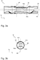
- FIG. 3a shows a side sectional view, wherein a central axis 38 of the measuring tube 14 runs along the x-axis from left to right in the direction of flow of the liquid flowing through.
- Fig. 3b shows a sectional view orthogonal to the central axis 38 of the measuring tube 14 in the region of the measuring channel 26 (cross section). The sectional plane 40 runs in the region of the liquid entry into the measuring channel 26.
- the measuring channel 26 is arranged eccentrically to the measuring tube 14 in the area of the sectional plane 40.
- the measuring channel 26 is arranged in the area of its entry in the sectional plane 40 offset upwards in the measuring tube 14.
- the measuring channel 26 has a rectangular cross section.
- the cross-sectional area increases in the direction of flow.
- the central axis 38 of the measuring tube 14 and a central axis 42 of the measuring channel 26 do not run parallel.
- the central axis 42 of the measuring channel 26 is to be understood as the axis that runs in the middle of the measuring channel 26.
- the center is the intersection of the diagonals of the cross-sectional rectangle.
- three inner surfaces of the measuring channel 44a, 44b, 44c run parallel to the central axis 38 of the measuring tube 14.
- Another inner surface 44d does not run parallel to the central axis 38 of the measuring tube, but falls in the direction of flow of the flowing liquid. This results in the expansion of the cross section of the measuring channel 26 in the direction of flow of the liquid.
- the increasing cross-sectional area results in a homogeneous flow within the measuring channel 26, which allows a precise measurement of the flow rate.
Abstract
Die vorliegende Erfindung betrifft ein Messrohr (14) aus ultraschallabsorbierendem Kunststoff für einen Ultraschall-Durchflussmengenmesser (10) zum Bestimmen einer Menge einer durchfließenden Flüssigkeit, mit: einer ersten Öffnung (22a) im Messrohr zum Einleiten eines Ultraschallsignals (24) in die durchfließende Flüssigkeit und einer zweiten Öffnung (22b) im Messrohr zum Ausleiten des Ultraschallsignals aus der durchfließenden Flüssigkeit, die mit Abstand hintereinander entlang des Messrohrs angeordnet sind; einem Messkanal (26) innerhalb des Messrohrs, der sich zwischen den zwei Öffnungen erstreckt und von der durchfließenden Flüssigkeit durchflossen wird; und mindestens zwei Umlenkbereichen (18a, 18b, 18c) zum Aufnehmen von jeweils einem Umlenkspiegel (16a, 16b, 16c), um das Ultraschallsignal durch Reflexion von der ersten Öffnung durch den Messkanal zu der zweiten Öffnung weiterzuleiten, wobei der Messkanal in einem Querschnitt senkrecht zur Flussrichtung der durchfließenden Flüssigkeit rechteckig ausgebildet ist und eine sich in Flussrichtung der Flüssigkeit vergrößernde Querschnittsfläche aufweist. Die vorliegende Erfindung betriff weiterhin einen Ultraschall-Durchflussmengenmesser (10) zum Bestimmen einer Menge einer durchfließenden Flüssigkeit sowie ein Verfahren zum Herstellen eines Messrohrs (14).The invention relates to a measuring tube (14) made of ultrasound-absorbing plastic for an ultrasonic flow meter (10) for determining an amount of a flowing fluid, comprising: a first opening (22a) in the measuring tube for introducing an ultrasonic signal (24) into the flowing fluid and a second opening (22b) in the measuring tube for discharging the ultrasonic signal from the liquid flowing through, which are arranged at a distance one behind the other along the measuring tube; a measuring channel (26) within the measuring tube, which extends between the two openings and through which the flowing liquid flows; and at least two deflection areas (18a, 18b, 18c) for receiving a deflection mirror (16a, 16b, 16c) in each case in order to transmit the ultrasound signal by reflection from the first opening through the measurement channel to the second opening, the measurement channel being perpendicular in a cross section is rectangular to the direction of flow of the liquid flowing through and has a cross-sectional area increasing in the direction of flow of the liquid. The present invention further relates to an ultrasonic flow meter (10) for determining an amount of a liquid flowing through and a method for producing a measuring tube (14).
Description
Die vorliegende Erfindung betrifft einen Ultraschall-Durchflussmengenmesser zum Bestimmen einer Menge einer durchfließenden Flüssigkeit, ein Messrohr aus ultraschallabsorbierendem Kunststoff für einen solchen Ultraschall-Durchflussmengenmesser sowie ein Verfahren zum Herstellen des Messrohrs.The present invention relates to an ultrasonic flow meter for determining a quantity of a liquid flowing through, a measuring tube made of ultrasound-absorbing plastic for such an ultrasonic flow meter and a method for producing the measuring tube.
Solche Durchflussmengenmesser werden beispielsweise in Wärmezählern zur Bestimmung des Verbrauchs von Wärme in Heizungsanlagen verwendet. Dazu wird das Volumen des warmen Wassers, das durch den Messkanal strömt, gemessen. Gleichzeitig wird die Temperaturdifferenz zwischen zwei Messpunkten im Vor- und Rücklauf gemessen. Aus diesen beiden Messungen kann dann der Wärmezähler die verbrauchte Wärmemenge ermitteln.Such flow meters are used, for example, in heat meters to determine the consumption of heat in heating systems. The volume of the warm water flowing through the measuring channel is measured. At the same time, the temperature difference between two measuring points in the flow and return is measured. The heat meter can then determine the amount of heat consumed from these two measurements.
Die vorliegende Erfindung betrifft insbesondere Ultraschall-Durchflussmengenmesser mit zwei Ultraschallwandlern, die ein Ultraschallsignal in ein Messrohr aus ultraschallabsorbierendem Kunststoff einleiten. Innerhalb des Messrohrs ist ein Messkanal angeordnet, der von der Flüssigkeit durchflossen wird. Weiterhin sind innerhalb des Messrohrs mindestens zwei Umlenkspiegel so angeordnet, dass das Ultraschallsignal von einem Ultraschallwandler zum anderen weitergeleitet wird. Dabei wird das Ultraschallsignal zumindest teilweise in bzw. gegen die Flussrichtung durch den Messkanal und die durchfließende Flüssigkeit geleitet. Basierend auf dem empfangenen Ultraschallsignal kann dann die Durchflussmenge ermittelt werden.The present invention relates in particular to ultrasonic flow meters with two ultrasonic transducers which introduce an ultrasonic signal into a measuring tube made of ultrasound-absorbing plastic. A measuring channel, through which the liquid flows, is arranged inside the measuring tube. Furthermore, at least two deflection mirrors are arranged within the measuring tube in such a way that the ultrasound signal from one ultrasound transducer to the other is forwarded. The ultrasound signal is at least partially guided in or against the direction of flow through the measuring channel and the liquid flowing through. The flow rate can then be determined based on the received ultrasound signal.
Üblicherweise sind die Rohrleitungssysteme, in denen ein Ultraschall-Durchflussmengenmesser zum Einsatz kommt, aus Metall. Metallische Gehäuse haben die Eigenschaft, Ultraschallsignale zu reflektieren und damit einer präzisen Messung abträglich zu sein. Kunststoff hat im Gegensatz dazu die Eigenschaft, Ultraschallwellen kaum zu reflektieren, stattdessen aufzunehmen und gut zu absorbieren. Durch die Verwendung eines Messrohrs aus ultraschallabsorbierendem Kunststoff werden unerwünschte Reflexionen an den Wänden des Ultraschall-Durchflussmengenmessers und eine unkontrollierte Ausbreitung eingekoppelter Schwingungen als Körperschall minimiert. Ein solches Messrohr kann beispielsweise innerhalb eines Metallgehäuses verwendet werden. Die Genauigkeit der Ultraschall-Messung wird verbessert.The piping systems in which an ultrasonic flow meter is used are usually made of metal. Metallic housings have the property of reflecting ultrasonic signals and thus being detrimental to a precise measurement. In contrast, plastic has the property of hardly reflecting ultrasound waves, instead picking them up and absorbing them well. By using a measuring tube made of ultrasound-absorbing plastic, unwanted reflections on the walls of the ultrasound flow meter and an uncontrolled propagation of coupled vibrations as structure-borne noise are minimized. Such a measuring tube can, for example, be used within a metal housing. The accuracy of the ultrasonic measurement is improved.
Ein Ultraschall-Durchflussmengenmesser ist beispielsweise aus der
Bei bisherigen Ansätzen zur Ausgestaltung des Messrohrs aus ultraschallabsorbierendem Kunststoff war die Überlegung, über eine geschickte Anordnung der Umlenkspiegel und über eine möglichst ungestörte Strömung in einem Messkanal innerhalb des Messrohrs eine genaue Messung sicherzustellen. Dennoch beeinflussen die Umlenkspiegel die Strömung im Messrohr und können damit die Genauigkeit der Durchflussmengenmessung beeinträchtigen.In previous approaches to designing the measuring tube from ultrasound-absorbing plastic, the idea had to be to ensure an accurate measurement by cleverly arranging the deflecting mirrors and by ensuring the flow in a measuring channel within the measuring tube was as undisturbed as possible. However, the deflection mirrors influence the flow in the measuring tube and can therefore impair the accuracy of the flow rate measurement.
Ausgehend hiervon stellt sich der vorliegenden Erfindung die Aufgabe, eine möglichst exakte Messung einer Menge einer durchfließenden Flüssigkeit zu ermöglichen. Insbesondere soll innerhalb eines Messkanals in einem Messrohr eine möglichst homogene Strömung der durchfließenden Flüssigkeit erreicht werden, um eine präzise Messung mittels des Ultraschallsignals zu ermöglichen.Proceeding from this, the object of the present invention is to enable the most exact possible measurement of an amount of a liquid flowing through. In particular, the most homogeneous possible flow of the liquid flowing through is to be achieved within a measuring channel in a measuring tube in order to enable a precise measurement by means of the ultrasonic signal.
Zum Lösen dieser Aufgabe betrifft die vorliegende Erfindung in einem ersten Aspekt ein Messrohr aus ultraschallabsorbierendem Kunststoff für einen Ultraschall-Durchflussmengenmesser zum Bestimmen einer Menge einer durchfließenden Flüssigkeit, mit:
- einer ersten Öffnung im Messrohr zum Einleiten eines Ultraschallsignals in die durchfließende Flüssigkeit und einer zweiten Öffnung im Messrohr zum Ausleiten des Ultraschallsignals aus der durchfließenden Flüssigkeit, die mit Abstand hintereinander entlang des Messrohrs angeordnet sind;
- einem Messkanal innerhalb des Messrohrs, der sich zwischen den zwei Öffnungen erstreckt und von der durchfließenden Flüssigkeit durchflossen wird; und
- mindestens zwei Umlenkbereichen zum Aufnehmen von jeweils einem Umlenkspiegel, um das Ultraschallsignal durch Reflexion von der ersten Öffnung durch den Messkanal zu der zweiten Öffnung weiterzuleiten, wobei
- der Messkanal in einem Querschnitt senkrecht zur Flussrichtung der durchfließenden Flüssigkeit rechteckig ausgebildet ist und eine sich in Flussrichtung der Flüssigkeit vergrößernde Querschnittsfläche aufweist.
- a first opening in the measuring tube for introducing an ultrasonic signal into the flowing fluid and a second opening in the measuring tube for discharging the ultrasonic signal from the flowing fluid, which are arranged at a distance one behind the other along the measuring tube;
- a measuring channel within the measuring tube, which extends between the two openings and through which the flowing liquid flows; and
- at least two deflection areas for receiving a deflection mirror each, in order to transmit the ultrasound signal by reflection from the first opening through the measuring channel to the second opening, wherein
- the measuring channel is rectangular in a cross section perpendicular to the flow direction of the liquid flowing through and has a cross-sectional area that increases in the flow direction of the liquid.
In einem weiteren Aspekt betrifft die Erfindung einen Ultraschall-Durchflussmengenmesser zum Bestimmen einer Menge einer durchfließenden Flüssigkeit, mit:
- einem Messrohr wie zuvor beschrieben;
- jeweils einem Umlenkspiegel in den Umlenkbereichen;
- einem ersten Ultraschallwandler, der zum Senden und Empfangen des Ultraschallsignals an die erste Öffnung im Messrohr angekoppelt ist;
- einem zweiten Ultraschallwandler, der zum Empfangen und Senden des Ultraschallsignals an die zweite Öffnung im Messrohr angekoppelt ist; und
- einem Anschluss zum Verbinden der Ultraschallwandler mit einem Prozessor zum Ansteuern der Ultraschallwandler, um basierend auf einer Auswertung des Ultraschallsignals nach Durchlaufen der durchfließenden Flüssigkeit eine Durchflussmenge zu ermitteln.
- a measuring tube as previously described;
- one deflection mirror each in the deflection areas;
- a first ultrasonic transducer which is coupled to the first opening in the measuring tube for transmitting and receiving the ultrasonic signal;
- a second ultrasonic transducer, which is coupled to receive and transmit the ultrasonic signal to the second opening in the measuring tube; and
- a connection for connecting the ultrasound transducers to a processor for actuating the ultrasound transducers in order to determine a flow rate based on an evaluation of the ultrasound signal after passing through the flowing liquid.
In einem weiteren Aspekt betrifft die Erfindung ein Verfahren zum Herstellen eines Messrohrs wie zuvor beschrieben, wobei die Umlenkspiegel in einem Spritzgussprozess in das Messrohr miteingespritzt werden.In a further aspect, the invention relates to a method for producing a measuring tube as described above, the deflecting mirrors being injected into the measuring tube in an injection molding process.
Bevorzugte Ausgestaltungen der Erfindung werden in den abhängigen Ansprüchen beschrieben. Es versteht sich, dass die vorstehend genannten und die nachstehend noch zu erläuternden Merkmale nicht nur in der jeweils angegebenen Kombination, sondern auch in anderen Kombinationen oder in Alleinstellung verwendbar sind, ohne den Rahmen der vorliegenden Erfindung zu verlassen. Insbesondere können das Messrohr und der Ultraschall-Durchflussmengenmesser sowie das Herstellungsverfahren entsprechend der für das Messrohr und den Ultraschall-Durchflussmengenmesser in den abhängigen Ansprüchen beschriebenen Ausgestaltungen ausgeführt sein.Preferred embodiments of the invention are described in the dependent claims. It goes without saying that the features mentioned above and those yet to be explained below can be used not only in the combination indicated in each case, but also in other combinations or on their own without departing from the scope of the present invention. In particular, the measuring tube and the ultrasonic flow meter and the production method can be designed in accordance with the configurations described for the measuring tube and the ultrasonic flow meter in the dependent claims.
Erfindungsgemäß wird ein Messrohr bereitgestellt, das sich zum Verwenden in einem Ultraschall-Durchflussmengenmesser eignet. Das Messrohr und der Messkanal im Messrohr werden von einer Flüssigkeit durchflossen, insbesondere von Wasser. Mittels eines Ultraschallwandlers wird ein Ultraschallsignal generiert und in die durchfließende Flüssigkeit eingeleitet. Nachdem das Ultraschallsignal durch den Messkanal und durch die innerhalb des Messkanals befindliche durchfließende Flüssigkeit geleitet wurde, wird es vom zweiten Ultraschallwandler empfangen. Ausgehend von einer Auswertung des empfangenen Ultraschallsignals kann basierend auf der Beeinflussung des Ultraschallsignals durch die Fließgeschwindigkeit der durchfließenden Flüssigkeit auf die Durchflussmenge rückgeschlossen werden. Hierzu wird üblicherweise die durchfließende Flüssigkeit mindestens jeweils einmal in und gegen die Flussrichtung durchlaufen. Beide Ultraschallwandler sind insoweit zumeist zum Senden und Empfangen des Ultraschallsignals ausgebildet.According to the invention, a measuring tube is provided which is suitable for use in an ultrasonic flow meter. A liquid, in particular water, flows through the measuring tube and the measuring channel in the measuring tube. An ultrasound signal is generated by means of an ultrasound transducer and introduced into the liquid flowing through. After the ultrasound signal has been passed through the measuring channel and through the flowing liquid located within the measuring channel, it is received by the second ultrasound transducer. Based on an evaluation of the received ultrasound signal, the flow rate can be inferred based on the influence of the ultrasound signal by the flow rate of the liquid flowing through. For this purpose, the liquid flowing through is usually passed at least once in and against the direction of flow. In this respect, both ultrasonic transducers are mostly designed to transmit and receive the ultrasonic signal.
Erfindungsgemäß ist es vorgesehen, dass der Messkanal rechteckig ausgebildet ist und eine sich in Flussrichtung der Flüssigkeit vergrößernde Querschnittsfläche aufweist. Es hat sich gezeigt, dass eine Verwendung eines Messkanals mit einem sich in Flussrichtung vergrößernden Querschnitt eine erhöhte Messgenauigkeit bewirkt. Durch die Vergrößerung des Querschnitts innerhalb des Messkanals wird eine Verlangsamung der Fließgeschwindigkeit beim Durchströmen des Messkanals erreicht. Hierdurch erhöht sich eine Homogenität der Strömung über den Querschnitt. Verwirbelungen werden reduziert. Durch einen rechteckigen Querschnitt im Bereich des Messkanals kann eine effiziente Fertigbarkeit erreicht werden. Zudem wird eine homogene Strömung im Messkanal gewährleistet. Im Vergleich zu bisherigen Ansätzen mit konstantem Querschnitt des Messkanals kann eine Durchflussmenge mit höherer Präzision ermittelt werden.According to the invention, it is provided that the measuring channel is rectangular and has a cross-sectional area that increases in the direction of flow of the liquid. It has been shown that the use of a measuring channel with a cross section that increases in the direction of flow results in increased measuring accuracy. By increasing the cross section within the measuring channel, the flow velocity is slowed down when flowing through the measuring channel. This increases the homogeneity of the flow across the cross section. Turbulence is reduced. A rectangular cross section in the area of the measuring channel enables efficient producibility to be achieved. In addition, a homogeneous flow in the measuring channel is guaranteed. In comparison to previous approaches with a constant cross-section of the measuring channel, a flow rate can be determined with greater precision.
In einer bevorzugten Ausgestaltung ist eine Zentralachse des Messkanals entlang der Flussrichtung der durchfließenden Flüssigkeit nicht deckungsgleich mit einer Zentralachse des Messrohrs entlang der Flussrichtung der durchfließenden Flüssigkeit. Die Zentralachse des Messkanals verläuft durch die Diagonalenschnittpunkte der rechteckigen Querschnittsfläche des Messkanals. Die Zentralachse des Messrohrs ergibt sich als Zentralachse einer das Messrohr umschließenden Form. Insbesondere kann das Messrohr im Wesentlichen zylinderförmig sein. Die Zentralachse ergibt sich dann als Zentralachse des Zylinders. Beide Zentralachsen sind vorzugsweise nicht deckungsgleich. Der Messkanal ist exzentrisch in Bezug zum Messrohr angeordnet. Hierdurch wird eine homogene strömungstechnische Beeinflussung des Ultraschallsignals erreicht. Die Genauigkeit der Messung der Durchflussmenge kann weiter gesteigert werden.In a preferred embodiment, a central axis of the measuring channel along the direction of flow of the liquid flowing through is not congruent with a central axis of the measuring tube along the direction of flow of the liquid flowing through. The central axis of the measuring channel runs through the Diagonal intersections of the rectangular cross-sectional area of the measuring channel. The central axis of the measuring tube results as the central axis of a shape enclosing the measuring tube. In particular, the measuring tube can be essentially cylindrical. The central axis then results as the central axis of the cylinder. Both central axes are preferably not congruent. The measuring channel is arranged eccentrically in relation to the measuring tube. This achieves a homogeneous fluidic influence on the ultrasound signal. The accuracy of the flow rate measurement can be further increased.
In einer bevorzugten Ausgestaltung verlaufen die Zentralachse des Messkanals und die Zentralachse des Messrohrs nicht parallel. Der Messkanal weitet sich in anderen Worten auf, wobei jedoch die Aufweitung der Querschnittsfläche des Messkanals nicht in senkrechter und waagerechter Richtung gleichmäßig erfolgt. Es ergibt sich sozusagen ein konischer Messkanal. Der Messkanal weitet sich ungleichmäßig auf, was eine Zentralachse des Messkanals bedingt, die nicht parallel zu der Zentralachse des Messrohrs verläuft. Die Messgenauigkeit wird durch die weitere Vermeidung von Verwirbelungen gesteigert.In a preferred embodiment, the central axis of the measuring channel and the central axis of the measuring tube are not parallel. In other words, the measuring channel widens, but the widening of the cross-sectional area of the measuring channel does not take place uniformly in the vertical and horizontal directions. A conical measuring channel results, so to speak. The measuring channel widens unevenly, which requires a central axis of the measuring channel that is not parallel to the central axis of the measuring tube. The measurement accuracy is increased by further avoiding turbulence.
In einer vorteilhaften Ausgestaltung verlaufen mindestens zwei, vorzugsweise drei, Innenflächen des Messkanals parallel zu einer Zentralachse des Messrohrs. Eine Innenfläche des Messkanals ist dabei eine Fläche, die mit der durchfließenden Flüssigkeit in Kontakt steht. Der Messkanal hat im Wesentlichen vier Innenflächen, wobei es möglich ist, dass eine Innenfläche zumindest teilweise von einem Umlenkspiegel innerhalb des Messkanals gebildet wird. Mindestens zwei, bevorzugt drei, Innenflächen dieses Messkanals verlaufen parallel zu einer Zentralachse des Messrohrs. Dies hat zur Folge, dass höchstens zwei, mindestens eine, Innenflächen nicht parallel zur Zentralachse des Messrohrs verlaufen, sondern sich in Richtung der durchfließenden Flüssigkeit von der Zentralachse des Messrohrs entfernen. Der Messkanal weitet sich auf. Verwirbelungen werden vermieden. Die Genauigkeit bei der Messung wird gesteigert.In an advantageous embodiment, at least two, preferably three, inner surfaces of the measuring channel run parallel to a central axis of the measuring tube. An inner surface of the measuring channel is a surface that is in contact with the liquid flowing through. The measuring channel essentially has four inner surfaces, it being possible for an inner surface to be at least partially formed by a deflecting mirror within the measuring channel. At least two, preferably three, inner surfaces of this measuring channel run parallel to a central axis of the measuring tube. As a result, at most two, at least one, inner surfaces do not run parallel to the central axis of the measuring tube, but rather move away from the central axis of the measuring tube in the direction of the liquid flowing through. The measuring channel widens. Turbulence is avoided. The accuracy of the measurement is increased.
In einer vorteilhaften Ausgestaltung umfasst das Messrohr ein Oberteil und ein mit dem Oberteil koppelbares Unterteil. Der Messkanal wird von Ober- und Unterteil begrenzt. Vorzugsweise weist der Messkanal im Querschnitt senkrecht zur Flussrichtung der durchfließenden Flüssigkeit einen ersten U-förmigen Abschnitt im Oberteil und einen zweiten U-förmigen Abschnitt im Unterteil auf. Der Messkanal verläuft teilweise im Ober- und teilweise im Unterteil. Die beiden U-förmigen Abschnitte ergeben zusammen den Messkanal mit rechteckigem Querschnitt. Ober- und Unterteil werden auch als Ober- und Unterschale bezeichnet. Das Messrohr ist sozusagen zusammensetzbar. Durch die Zusammensetzbarkeit wird eine einfachere Herstellbarkeit erreicht. Beide Teile können beispielsweise im Spritzgussverfahren hergestellt werden. Zudem kann eine einfache und effiziente Montage der Umlenkspiegel in die Umlenkbereiche erfolgen.In an advantageous embodiment, the measuring tube comprises an upper part and a lower part that can be coupled to the upper part. The measuring channel is limited by the upper and lower part. The cross section of the measuring channel preferably has a first U-shaped section in the upper part and a second U-shaped section in the lower part perpendicular to the flow direction of the liquid flowing through. The measuring channel runs partly in the upper and partly in the lower part. The two U-shaped sections together form the measuring channel with a rectangular cross-section. The upper and lower part are also referred to as the upper and lower shell. The measuring tube can be put together, so to speak. The assemblability makes it easier to manufacture. Both parts can be manufactured, for example, by injection molding. In addition, the deflection mirrors can be easily and efficiently installed in the deflection areas.
In einer vorteilhaften Ausgestaltung ist zwischen Ober- und Unterteil im Bereich des Messkanals zum Abdichten auf beiden Seiten des Messkanals eine Labyrinth-Verbindung angeordnet. Die Labyrinth-Verbindung umfasst eine Nut an dem einen Teil des Ober- und Unterteils und einen in die Nut eingreifenden Vorsprung an dem anderen Teil des Ober- und Unterteils. Eine Labyrinth-Verbindung bezeichnet eine Verbindung, bei der ein Vorsprung, also ein Überstand, in eine Nut, also eine Art Kanal, eingreift. Der Verlauf der Labyrinth-Verbindung ist dabei nicht geradlinig, sondern weist mindestens eine Richtungsänderung auf. Durch die Labyrinth-Verbindung wird eine Abdichtung zwischen Ober- und Unterteil sichergestellt. Es wird verhindert, dass Flüssigkeit aus dem Messkanal ausströmt. Hierdurch werden Strömungen durch ausströmende Flüssigkeit innerhalb des Messkanals vermieden, die die Homogenität der Strömung innerhalb des Messkanals beeinträchtigen könnten. Die Genauigkeit bei der Messung der Durchflussmenge kann weiter verbessert werden.In an advantageous embodiment, a labyrinth connection is arranged between the upper and lower part in the area of the measuring channel for sealing on both sides of the measuring channel. The labyrinth connection comprises a groove on one part of the upper and lower part and a projection engaging in the groove on the other part of the upper and lower part. A labyrinth connection refers to a connection in which a protrusion, i.e. a protrusion, engages in a groove, that is to say a type of channel. The course of the labyrinth connection is not straight, but has at least one change of direction. The labyrinth connection ensures a seal between the upper and lower part. It prevents liquid from flowing out of the measuring channel. This avoids flows through liquid flowing out within the measuring channel, which could impair the homogeneity of the flow within the measuring channel. The accuracy in measuring the flow rate can be further improved.
In einer vorteilhaften Ausgestaltung erstreckt sich dabei der Vorsprung zumindest auf der einen Seite des Messkanals über die gesamte Länge des Messrohrs. Zusätzlich oder alternativ erstreckt sich die Nut im Wesentlichen entlang des Messkanals. Durch die Verwendung eines relativ langen Vorsprungs kann über die gesamte Länge eine Abdichtung erreicht werden. Ausfließende und eindringende Flüssigkeit wird vermieden. Wie zuvor beschrieben ergibt sich hieraus eine verbesserte Messgenauigkeit.In an advantageous embodiment, the projection extends at least on one side of the measuring channel over the entire length of the measuring tube. Additionally or alternatively, the groove extends essentially along the measuring channel. By using a relatively long projection A seal can be achieved over the entire length. Leaking and penetrating liquid is avoided. As described above, this results in improved measurement accuracy.
Vorzugsweise umfasst das Messrohr drei Umlenkbereiche. Zwei Öffnungs-Umlenkbereiche sind im Messrohr gegenüberliegend von den beiden Öffnungen angeordnet. Ein Innenflächen-Umlenkbereich ist an einer Innenfläche des Messkanals angeordnet. Die Öffnungs-Umlenkbereiche und der Innenflächen-Umlenkbereich sind so angeordnet, dass das Ultraschallsignal nach dem Einleiten in die durchfließende Flüssigkeit auf einen ersten Umlenkspiegel in einem der beiden Öffnungs-Umlenkbereiche auftrifft, von diesem ersten Umlenkspiegel auf einen dritten Umlenkspiegel in dem Innenflächen-Umlenkbereich reflektiert wird, von diesem dritten Umlenkspiegel auf einen zweiten Umlenkspiegel im anderen Öffnungs-Umlenkbereich reflektiert wird und von diesem zweiten Umlenkspiegel ausgeleitet wird. In anderen Worten ergibt sich ein W- bzw. M-förmiger Weg des Ultraschallsignals. Durch die Kombination des W- oder M-förmigen Wegs des Ultraschallsignals (Messstrecke) durch den Messkanal mit dem sich in Flussrichtung der Flüssigkeit vergrößernden Querschnitt des Messkanals können Totwasserbereiche im Umfeld der Umlenkspiegel weitestgehend vermieden werden. Im Auslassbereich kann die Überhöhung am hinteren Spiegel vergrößert werden, um den Einfluss eines sich daran ablösenden Wirbels möglichst gering zu halten. Eine homogene Strömung im Messkanal wird erreicht, wodurch sich eine verbesserte Messgenauigkeit ergibt.The measuring tube preferably comprises three deflection areas. Two opening deflection areas are arranged opposite the two openings in the measuring tube. An inner surface deflection area is arranged on an inner surface of the measuring channel. The opening deflection regions and the inner surface deflection region are arranged such that the ultrasound signal, after being introduced into the liquid flowing through, strikes a first deflection mirror in one of the two opening deflection regions, is reflected by this first deflection mirror on a third deflection mirror in the inner surface deflection region is reflected by this third deflecting mirror onto a second deflecting mirror in the other opening deflecting region and is diverted from this second deflecting mirror. In other words, a W- or M-shaped path of the ultrasound signal results. By combining the W- or M-shaped path of the ultrasonic signal (measuring section) through the measuring channel with the cross-section of the measuring channel increasing in the direction of flow of the liquid, dead water areas in the vicinity of the deflecting mirror can be largely avoided. In the outlet area, the elevation on the rear mirror can be increased in order to keep the influence of a vortex detached from it as small as possible. A homogeneous flow in the measuring channel is achieved, which results in improved measuring accuracy.
Vorzugsweise sind die Umlenkbereiche zum Aufnehmen von Metallplättchen als Umlenkspiegel ausgebildet. Die Metallplättchen können eingelegt werden oder auch, bevorzugt, in einem Spritzgussprozess in das Messrohr miteingespritzt werden. Hierdurch ergibt sich eine effiziente Herstellbarkeit und eine zuverlässige Reflexion des Ultraschallsignals innerhalb des Messrohrs.The deflection regions for receiving metal plates are preferably designed as deflection mirrors. The metal plates can be inserted or, preferably, also injected into the measuring tube in an injection molding process. This results in an efficient producibility and a reliable reflection of the ultrasound signal within the measuring tube.
In einer vorteilhaften Ausgestaltung umfasst das Messrohr eine umlaufende Vertiefung im Umfang zum Aufnehmen eines Dichtelements, um einen Zwischenraum zwischen Messrohr und Ultraschall-Durchflussmengenmesser abzudichten und einen Flüssigkeitsfluss außerhalb des Messrohrs zu unterbinden. Hierdurch kann die Homogenität der Strömung bereits beim Ein- und Ausfließen in das Messrohr weiter verbessert werden. Die Genauigkeit der Messung kann weiter gesteigert werden.In an advantageous embodiment, the measuring tube comprises a circumferential recess in the circumference for receiving a sealing element, around an intermediate space between the measuring tube and the ultrasonic flow meter seal and prevent liquid flow outside the measuring tube. As a result, the homogeneity of the flow can be further improved as it flows into and out of the measuring tube. The accuracy of the measurement can be further increased.
In einer bevorzugten Ausgestaltung umfasst der Ultraschall-Durchflussmengenmesser ein Metallgehäuse zum Einkoppeln in ein Rohrleitungssystem. Das Messrohr ist innerhalb des Metallgehäuses form- und/oder kraftschlüssig befestigt, vorzugsweise mit einer Schraube. In vielen Anwendungen werden Metallrohre verwendet. Metallrohre reflektieren Ultraschall, sodass eine zuverlässige Messung schwierig ist. Durch die Verwendung eines Messrohrs aus ultraschallabsorbierendem Kunststoff kann innerhalb eines Metallrohrs eine zuverlässige Messung erreicht werden. Durch eine form- und/oder kraftschlüssige Befestigung innerhalb des Metallgehäuses kann ein Verrutschen oder Lösen des Messrohrs vermieden werden. Zudem kann eine Umströmung weitestgehend vermieden werden, um eine Messung mit hoher Genauigkeit zu erlauben.In a preferred embodiment, the ultrasonic flow meter comprises a metal housing for coupling into a piping system. The measuring tube is fastened positively and / or non-positively within the metal housing, preferably with a screw. Metal pipes are used in many applications. Metal pipes reflect ultrasound, making reliable measurement difficult. By using a measuring tube made of ultrasound-absorbing plastic, a reliable measurement can be achieved within a metal tube. Slipping or loosening of the measuring tube can be avoided by a positive and / or non-positive fastening within the metal housing. In addition, flow around can be largely avoided to allow measurement with high accuracy.
Die Erfindung wird nachfolgend anhand einiger ausgewählter Ausführungsbeispiele im Zusammenhang mit den beiliegenden Zeichnungen näher beschrieben und erläutert. Es zeigen:
- Figur 1
- eine schematische Schnittdarstellung eines erfindungsgemäßen Ultraschall-Durchflussmengenmessers zum Bestimmen einer Menge einer durchfließenden Flüssigkeit;
- Figur 2
- eine perspektivische Darstellung eines erfindungsgemäßen Messrohrs mit Ober- und Unterteil;
- Figur 3a
- eine schematische Schnittdarstellung des Messrohrs parallel zu einer Zentralachse des Messrohrs; und
- Figur 3b
- eine schematische Schnittdarstellung des Messrohrs senkrecht zur Zentralachse des Messrohrs.
- Figure 1
- is a schematic sectional view of an ultrasonic flow meter according to the invention for determining an amount of a flowing fluid;
- Figure 2
- a perspective view of a measuring tube according to the invention with upper and lower part;
- Figure 3a
- a schematic sectional view of the measuring tube parallel to a central axis of the measuring tube; and
- Figure 3b
- is a schematic sectional view of the measuring tube perpendicular to the central axis of the measuring tube.
In der
Weiterhin umfasst der Ultraschall-Durchflussmengenmesser 10 insgesamt drei Umlenkspiegel 16a, 16b, 16c, die in zwei Öffnungs-Umlenkbereichen 18a, 18b und einem Innenflächen-Umlenkbereich 18c des Messrohrs 14 angeordnet sind. Die drei Umlenkspiegel 16a, 16b, 16c können beispielsweise flache ebene Metallplättchen sein, deren Oberflächen poliert sind und die Spiegelflächen bilden. Die Metallplättchen werden die in die Umlenkbereiche eingelegt und beispielsweise festgeklebt. Vorteilhafterweise ist es möglich, dass die Umlenkspiegel 16a, 16b, 16c in einem Spritzgussprozess in das Messrohr 14 mit eingespritzt werden. Hierdurch kann eine effiziente Herstellbarkeit erreicht werden. Es kann aber auch ein anderes ultraschallreflektierendes Material verwendet werden und/oder eine Schicht aus ultraschallreflektierendem Metall aufgedampft werden.Furthermore, the
Zudem umfasst der Ultraschall-Durchflussmengenmesser 10 einen ersten Ultraschallwandler 20a und einen zweiten Ultraschallwandler 20b, die zum Senden und Empfangen eines Ultraschallsignals ausgebildet sind. Die Ultraschallwandler 20a, 20b sind mit einem Prozessor (nicht dargestellt) verbunden, über den sie angesteuert werden, um ein Ultraschallsignal 24 zu senden bzw. zu empfangen. Eine Bestimmung der Durchflussmenge kann basierend auf einer Auswertung des Ultraschallsignals 24 erfolgen, nachdem dieses Ultraschallsignal 24 einen innerhalb des Messrohrs 14 angeordneten Messkanal 26 durchlaufen hat. Die Genauigkeit der Messung der Durchflussmenge der durchfließenden Flüssigkeit hängt von einer Homogenität der Strömung innerhalb des Messkanals 26 ab.In addition, the
Die Ultraschallwandler 20a, 20b sind an eine erste Öffnung 22a und eine zweite Öffnung 22b im Messrohr 14 angekoppelt. Im dargestellten Ausführungsbeispiel ist die erste Öffnung 22a bzw. der erste Ultraschallwandler 20a gegenüber dem ersten Öffnungs-Umlenkbereich 18a bzw. gegenüber dem ersten Umlenkspiegel 16a angeordnet. Die zweite Öffnung 22b bzw. der zweite Ultraschallwandler 20b ist gegenüber dem zweiten Öffnungs-Umlenkbereich 18b bzw. gegenüber dem zweiten Umlenkspiegel 16b angeordnet.The
Ein durch eine der beiden Öffnungen 22a, 22b in das Messrohr 14 eingekoppeltes Ultraschallsignal 24 trifft auf einen der beiden Umlenkspiegel 16a, 16b in den Öffnungs-Umlenkbereichen 18a, 18b auf. Von dort wird es auf den dritten innerhalb des Messkanals 26 angeordneten Umlenkspiegel 16c im Innenflächen-Umlenkbereich 18c reflektiert. Von diesem wird es dann erneut an den anderen der beiden Umlenkspiegel 16a, 16b in den Öffnungs-Umlenkbereichen 18a, 18b reflektiert und durch die andere der beiden Öffnungen 22a, 22b ausgeleitet. Das Ultraschallsignal 24 kann dann von einem der beiden Ultraschallwandler 20a, 20b empfangen werden. Das Ultraschallsignal 24 legt zwischen den Ultraschallwandlern 20a, 20b damit einen im Prinzip W-förmigen Weg zurück.An
Wie dargestellt wird der Messkanal zumeist mindestens jeweils einmal in und entgegen der Fließrichtung der Flüssigkeit durchlaufen. Das Ultraschallsignal 24 verläuft in beide Richtungen. Einerseits kann der erste Ultraschallwandler 20a das Ultraschallsignal 24 aussenden und der zweite Ultraschallwandler 20b das Ultraschallsignal empfangen. Andererseits ist es möglich, dass der zweite Ultraschallwandler 20b das Ultraschallsignal 24 aussendet und der erste Ultraschallwandler 20a das Ultraschallsignal empfängt.As shown, the measurement channel is usually passed through at least once in and against the direction of flow of the liquid. The
In der
Der erste Öffnungs-Umlenkbereich 18a und der zweite Öffnungs-Umlenkbereich 18b sind im Unterteil 30 angeordnet. Der Innenflächen-Umlenkbereich 18c ist im Oberteil 28 angeordnet und in der perspektivischen Darstellung nicht sichtbar. Die Öffnungs-Umlenkbereiche 18a, 18b sind gegenüber den Öffnungen 22a, 22b angeordnet.The first
Im mittleren Bereich des Messrohrs 14 ist der Messkanal 26 angeordnet. Der Messkanal 26 hat einen Querschnitt, der senkrecht zur Flussrichtung (von links nach rechts in der Darstellung) der durchfließenden Flüssigkeit rechteckig ausgebildet ist. Im dargestellten Ausführungsbeispiel ist der Messkanal teilweise im Oberteil 28 und teilweise im Unterteil 30 angeordnet. Insbesondere ist sowohl im Oberteil 28 als auch im Unterteil 30 jeweils ein U-förmiger Abschnitt des Messkanals 26 angeordnet. Unter einem U-förmigen Abschnitt versteht sich ein Abschnitt mit rechteckigem Querschnitt, der einseitig in Richtung des jeweils anderen U-förmigen Abschnitts geöffnet ist. In anderen Worten verläuft ein Teil des Messkanals im Oberteil 28 und ein anderer Teil im Unterteil 30.The measuring
Für die Abdichtung zwischen Oberteil 28 und Unterteil 30 ist eine Labyrinth-Verbindung 32 vorgesehen. Die Labyrinth-Verbindung 32 umfasst dabei eine Nut 34 am Oberteil und einen in die Nut eingreifenden Vorsprung 36 am Unterteil 30. Sowohl die Nut 34 als auch der Vorsprung 36 sind symmetrisch auf beiden Seiten des Messkanals 26 angeordnet. Der Vorsprung 36 verläuft im dargestellten Beispiel auf beiden Seiten des Messkanals 26 über die gesamte Länge des Messrohrs 14. Die Nut 34 verläuft im dargestellten Ausführungsbeispiel im Wesentlichen entlang des Messkanals 26. Demnach verläuft die Nut 34 nicht über die gesamte Länge des Messrohrs 14, sondern lediglich über einen Teil davon, nämlich den Teil entlang des Messkanals 26. Durch die Labyrinth-Verbindung 32 wird sichergestellt, dass insbesondere im Bereich des Messkanals 26 eine möglichst dichte Verbindung zwischen Oberteil 28 und Unterteil 30 hergestellt wird. Es wird verhindert, dass Flüssigkeit ein- oder austritt und hierdurch Verwirbelungen bzw. eine inhomogene Strömung im Bereich des Messkanals 26 entsteht. Insoweit bewirkt die Labyrinth-Verbindung 32 eine Verbesserung der Homogenität der Strömung im Bereich des Messkanals 26.A
In den
Der Messkanal 26 ist im Bereich der Schnittebene 40 dabei exzentrisch zum Messrohr 14 angeordnet. In anderen Worten ist der Messkanal 26 im Bereich seines Eintritts in der Schnittebene 40 nach oben versetzt im Messrohr 14 angeordnet. Der Messkanal 26 weist einen rechteckigen Querschnitt auf. Die Querschnittsfläche vergrößert sich in Durchflussrichtung. Im dargestellten Beispiel verlaufen dabei die Zentralachse 38 des Messrohrs 14 und eine Zentralachse 42 des Messkanals 26 nicht parallel. Die Zentralachse 42 des Messkanals 26 ist dabei als diejenige Achse zu verstehen, die in der Mitte des Messkanals 26 verläuft. Im Querschnitt wird als Mitte dabei der Schnittpunkt der Diagonalen des Querschnittsrechtecks verstanden.The measuring
Im dargestellten Beispiel verlaufen drei Innenflächen des Messkanals 44a, 44b, 44c parallel zur Zentralachse 38 des Messrohrs 14. Eine weitere Innenfläche 44d verläuft nicht parallel zur Zentralachse 38 des Messrohrs, sondern fällt in Flussrichtung der durchfließenden Flüssigkeit ab. Hierdurch ergibt sich die Erweiterung des Querschnitts des Messkanals 26 in Flussrichtung der Flüssigkeit. Durch die sich vergrößernde Querschnittsfläche ergibt sich innerhalb des Messkanals 26 eine homogene Strömung, die eine präzise Messung der Durchflussmenge erlaubt.In the example shown, three inner surfaces of the measuring
Die Erfindung wurde anhand der Zeichnungen und der Beschreibung umfassend beschrieben und erklärt. Die Beschreibung und Erklärung sind als Beispiel und nicht einschränkend zu verstehen. Die Erfindung ist nicht auf die offenbarten Ausführungsformen beschränkt. Andere Ausführungsformen oder Variationen ergeben sich für den Fachmann bei der Verwendung der vorliegenden Erfindung sowie bei einer genauen Analyse der Zeichnungen, der Offenbarung und der nachfolgenden Patentansprüche.The invention has been described and explained comprehensively with reference to the drawings and the description. The description and explanation are to be understood as examples and not restrictive. The invention is not limited to the disclosed embodiments. Other embodiments or variations will occur to those skilled in the art using the present invention, as well as upon a detailed analysis of the drawings, the disclosure, and the following claims.
In den Patentansprüchen schließen die Wörter "umfassen" und "mit" nicht das Vorhandensein weiterer Elemente oder Schritte aus. Der undefinierte Artikel "ein" oder "eine" schließt nicht das Vorhandensein einer Mehrzahl aus. Ein einzelnes Element oder eine einzelne Einheit kann die Funktionen mehrerer der in den Patentansprüchen genannten Einheiten ausführen. Die bloße Nennung einiger Maßnahmen in mehreren verschiedenen abhängigen Patentansprüchen ist nicht dahingehend zu verstehen, dass eine Kombination dieser Maßnahmen nicht ebenfalls vorteilhaft verwendet werden kann. Bezugszeichen in den Patentansprüchen sind nicht einschränkend zu verstehen.In the claims, the words "comprise" and "with" do not exclude the presence of further elements or steps. The undefined article "a" or "an" does not preclude the existence of a plurality. A single element or a single unit can perform the functions of several of the units mentioned in the claims. The mere mention of some measures in several different dependent claims is not to be understood to mean that a combination of these measures cannot also be used advantageously. Reference signs in the claims are not to be understood as restrictive.
Claims (13)
eine Zentralachse (42) des Messkanals (26) entlang der Flussrichtung der durchfließenden Flüssigkeit nicht deckungsgleich mit einer Zentralachse (38) des Messrohrs entlang der Flussrichtung der durchfließenden Flüssigkeit ist.Measuring tube (14) according to claim 1, wherein
a central axis (42) of the measuring channel (26) along the flow direction of the flowing liquid is not congruent with a central axis (38) of the measuring tube along the flow direction of the flowing liquid.
das Messrohr ein Oberteil (28) und ein mit dem Oberteil koppelbares Unterteil (30) umfasst;
der Messkanal (26) von Ober- und Unterteil begrenzt wird; und
der Messkanal vorzugsweise im Querschnitt senkrecht zur Flussrichtung der durchfließenden Flüssigkeit einen ersten U-förmigen Abschnitt im Oberteil und einen zweiten U-förmigen Abschnitt im Unterteil aufweist.Measuring tube (14) according to any one of the preceding claims, wherein
the measuring tube comprises an upper part (28) and a lower part (30) which can be coupled to the upper part;
the measuring channel (26) is delimited by the upper and lower part; and
the measuring channel preferably has a first U-shaped section in the upper part and a second U-shaped section in the lower part in cross section perpendicular to the direction of flow of the liquid flowing through.
zwischen Oberteil (28) und Unterteil (30) im Bereich des Messkanals (26) zum Abdichten auf beiden Seiten des Messkanals eine Labyrinth-Verbindung (32) angeordnet ist; und
die Labyrinth-Verbindung eine Nut (34) an dem einen Teil des Ober- und Unterteils und einen in die Nut eingreifenden Vorsprung (36) an dem anderen Teil des Ober- und Unterteils umfasst.Measuring tube (14) according to claim 5, wherein
a labyrinth connection (32) is arranged between the upper part (28) and lower part (30) in the region of the measuring channel (26) for sealing on both sides of the measuring channel; and
the labyrinth connection comprises a groove (34) on one part of the upper and lower part and a projection (36) engaging in the groove on the other part of the upper and lower part.
sich der Vorsprung (36) zumindest auf der einen Seite des Messkanals (26) über die gesamte Länge des Messrohrs erstreckt; und/oder sich die Nut (34) im Wesentlichen entlang des Messkanals erstreckt.Measuring tube (14) according to claim 6, wherein
the projection (36) extends at least on one side of the measuring channel (26) over the entire length of the measuring tube; and or the groove (34) extends essentially along the measuring channel.
zwei Öffnungs-Umlenkbereiche (18a, 18b) im Messrohr gegenüberliegend von den beiden Öffnungen (22a, 22b) angeordnet sind;
ein Innenflächen-Umlenkbereich (18c) an einer Innenfläche des Messkanals (26) angeordnet ist; und
die Öffnungs-Umlenkbereiche und der Innenflächen-Umlenkbereich so angeordnet ist, dass das Ultraschallsignal (24) nach dem Einleiten in die durchfließende Flüssigkeit auf einen ersten Umlenkspiegel (16a, 16b) in einem der beiden Öffnungs-Umlenkbereiche auftrifft, von diesem ersten Umlenkspiegel auf einen dritten Umlenkspiegel (16c) in dem Innenflächen-Umlenkbereich reflektiert wird, von diesem dritten Umlenkspiegel auf einen zweiten Umlenkspiegel im anderen Öffnungs-Umlenkbereich reflektiert wird und von diesem zweiten Umlenkspiegel ausgeleitet wird.Measuring tube (14) according to one of the preceding claims, with three deflection areas (18a, 18b, 18c), wherein
two opening deflection regions (18a, 18b) are arranged in the measuring tube opposite the two openings (22a, 22b);
an inner surface deflection region (18c) is arranged on an inner surface of the measuring channel (26); and
the opening deflection areas and the inner surface deflection area are arranged in such a way that the ultrasound signal (24) strikes a first deflection mirror (16a, 16b) in one of the two opening deflection areas, from this first deflection mirror, after being introduced into the flowing liquid third deflecting mirror (16c) is reflected in the inner surface deflecting area, is reflected by this third deflecting mirror onto a second deflecting mirror in the other opening deflecting area and is derived from this second deflecting mirror.
Priority Applications (1)
| Application Number | Priority Date | Filing Date | Title |
|---|---|---|---|
| EP19150062.8A EP3677877A1 (en) | 2019-01-02 | 2019-01-02 | Measuring tube and ultrasonic flow meter |
Applications Claiming Priority (1)
| Application Number | Priority Date | Filing Date | Title |
|---|---|---|---|
| EP19150062.8A EP3677877A1 (en) | 2019-01-02 | 2019-01-02 | Measuring tube and ultrasonic flow meter |
Publications (1)
| Publication Number | Publication Date |
|---|---|
| EP3677877A1 true EP3677877A1 (en) | 2020-07-08 |
Family
ID=64949156
Family Applications (1)
| Application Number | Title | Priority Date | Filing Date |
|---|---|---|---|
| EP19150062.8A Withdrawn EP3677877A1 (en) | 2019-01-02 | 2019-01-02 | Measuring tube and ultrasonic flow meter |
Country Status (1)
| Country | Link |
|---|---|
| EP (1) | EP3677877A1 (en) |
Cited By (6)
| Publication number | Priority date | Publication date | Assignee | Title |
|---|---|---|---|---|
| WO2022119824A1 (en) * | 2020-12-05 | 2022-06-09 | Itron Global Sarl | Ultrasonic channel |
| CN115265689A (en) * | 2022-09-30 | 2022-11-01 | 济南沛华信息科技有限公司 | Ultrasonic reflection structure, measurement pipeline section and ultrasonic flowmeter |
| DE102021114657A1 (en) | 2021-06-08 | 2022-12-08 | Engelmann Sensor Gmbh | flow meter |
| US11650087B2 (en) | 2018-05-31 | 2023-05-16 | Sentec Ltd. | Ultrasonic meter including one or more pairs of ultrasonic transducers and two or more protrusions arranged to exclude fluid from non-sampled volume |
| WO2023156963A1 (en) * | 2022-02-18 | 2023-08-24 | Pietro Fiorentini S.P.A. | An improved device for fluid measuring |
| US11940308B2 (en) | 2020-12-05 | 2024-03-26 | Itron Global Sarl | Insert forming an ultrasonic channel for a fluid meter and including reflector mirrors and a flow stabilizer |
Citations (2)
| Publication number | Priority date | Publication date | Assignee | Title |
|---|---|---|---|---|
| WO2005005932A1 (en) * | 2003-07-15 | 2005-01-20 | Matsushita Electric Industrial Co., Ltd. | Flow measuring device |
| EP3199923A1 (en) | 2016-01-26 | 2017-08-02 | Engelmann Sensor GmbH | Ultrasonic flow meter |
-
2019
- 2019-01-02 EP EP19150062.8A patent/EP3677877A1/en not_active Withdrawn
Patent Citations (2)
| Publication number | Priority date | Publication date | Assignee | Title |
|---|---|---|---|---|
| WO2005005932A1 (en) * | 2003-07-15 | 2005-01-20 | Matsushita Electric Industrial Co., Ltd. | Flow measuring device |
| EP3199923A1 (en) | 2016-01-26 | 2017-08-02 | Engelmann Sensor GmbH | Ultrasonic flow meter |
Cited By (7)
| Publication number | Priority date | Publication date | Assignee | Title |
|---|---|---|---|---|
| US11650087B2 (en) | 2018-05-31 | 2023-05-16 | Sentec Ltd. | Ultrasonic meter including one or more pairs of ultrasonic transducers and two or more protrusions arranged to exclude fluid from non-sampled volume |
| WO2022119824A1 (en) * | 2020-12-05 | 2022-06-09 | Itron Global Sarl | Ultrasonic channel |
| US11940308B2 (en) | 2020-12-05 | 2024-03-26 | Itron Global Sarl | Insert forming an ultrasonic channel for a fluid meter and including reflector mirrors and a flow stabilizer |
| DE102021114657A1 (en) | 2021-06-08 | 2022-12-08 | Engelmann Sensor Gmbh | flow meter |
| EP4109055A1 (en) | 2021-06-08 | 2022-12-28 | Engelmann Sensor GmbH | Flow rate detector |
| WO2023156963A1 (en) * | 2022-02-18 | 2023-08-24 | Pietro Fiorentini S.P.A. | An improved device for fluid measuring |
| CN115265689A (en) * | 2022-09-30 | 2022-11-01 | 济南沛华信息科技有限公司 | Ultrasonic reflection structure, measurement pipeline section and ultrasonic flowmeter |
Similar Documents
| Publication | Publication Date | Title |
|---|---|---|
| EP3677877A1 (en) | Measuring tube and ultrasonic flow meter | |
| DE102013114475B4 (en) | Ultrasonic measuring device and method for determining the flow velocity | |
| EP3004812B1 (en) | Ultrasonic flowmeter | |
| EP1936333B1 (en) | Ultrasound flow measuring device | |
| DE102019110514B4 (en) | Fluid measuring device | |
| WO2007065557A1 (en) | Ultrasound measuring section made from plastic and corresponding measuring method | |
| EP3314214B1 (en) | Flowmeter with measuring flow channel and auxiliary flow channels | |
| EP3199923A1 (en) | Ultrasonic flow meter | |
| DE19530807A1 (en) | Volume flow meter | |
| EP2988103B1 (en) | Flow meter with a measuring insert that can be inserted into a housing | |
| EP3940346B1 (en) | Flow meter and method for measuring the flow rate of a fluid | |
| DE102019124454A1 (en) | Fluid measuring device with a fluid housing and method for producing a fluid housing | |
| EP0681162A1 (en) | Detector for ultrasonic measurement of fluid flows | |
| DE202019003218U1 (en) | Measuring tube and ultrasonic flow meter | |
| DE102010063789A1 (en) | Ultrasonic flowmeter | |
| EP3343185B1 (en) | Ultrasound flow measuring device and method for measuring the flow | |
| DE19944411A1 (en) | Ultrasonic flow measurement has profiled rectangular section measurement tube reduces resistance | |
| EP3139138A1 (en) | Measurement valve for a flow meter | |
| WO2003006932A1 (en) | Measuring head for an ultrasonic flow meter | |
| DE102011016109B4 (en) | Reflector arrangement for an ultrasonic flowmeter | |
| DE102020126021A1 (en) | Fluid measuring device | |
| DE202020104105U1 (en) | Flow meter for measuring the flow of a fluid | |
| EP3855134A1 (en) | Device for measuring the flow speed of a fluid | |
| DE102005062628B3 (en) | Ultrasonic flow meter for determining e.g. gas flow rate, has reflectors arranged in measuring section to switch ultrasonic signals, where course of direction of signals of transformers is diverged in coupling/decoupling areas of section | |
| EP4220097B1 (en) | Flow measuring system |
Legal Events
| Date | Code | Title | Description |
|---|---|---|---|
| PUAI | Public reference made under article 153(3) epc to a published international application that has entered the european phase |
Free format text: ORIGINAL CODE: 0009012 |
|
| STAA | Information on the status of an ep patent application or granted ep patent |
Free format text: STATUS: THE APPLICATION HAS BEEN PUBLISHED |
|
| AK | Designated contracting states |
Kind code of ref document: A1 Designated state(s): AL AT BE BG CH CY CZ DE DK EE ES FI FR GB GR HR HU IE IS IT LI LT LU LV MC MK MT NL NO PL PT RO RS SE SI SK SM TR |
|
| AX | Request for extension of the european patent |
Extension state: BA ME |
|
| STAA | Information on the status of an ep patent application or granted ep patent |
Free format text: STATUS: THE APPLICATION IS DEEMED TO BE WITHDRAWN |
|
| 18D | Application deemed to be withdrawn |
Effective date: 20210112 |