EP3677865A1 - Flat tube for microchannel heat exchanger, and microchannel heat exchanger - Google Patents
Flat tube for microchannel heat exchanger, and microchannel heat exchanger Download PDFInfo
- Publication number
- EP3677865A1 EP3677865A1 EP18858124.3A EP18858124A EP3677865A1 EP 3677865 A1 EP3677865 A1 EP 3677865A1 EP 18858124 A EP18858124 A EP 18858124A EP 3677865 A1 EP3677865 A1 EP 3677865A1
- Authority
- EP
- European Patent Office
- Prior art keywords
- wallboard
- protrusion
- flat tube
- protrusions
- groove
- Prior art date
- Legal status (The legal status is an assumption and is not a legal conclusion. Google has not performed a legal analysis and makes no representation as to the accuracy of the status listed.)
- Granted
Links
Images



Classifications
-
- F—MECHANICAL ENGINEERING; LIGHTING; HEATING; WEAPONS; BLASTING
- F28—HEAT EXCHANGE IN GENERAL
- F28F—DETAILS OF HEAT-EXCHANGE AND HEAT-TRANSFER APPARATUS, OF GENERAL APPLICATION
- F28F1/00—Tubular elements; Assemblies of tubular elements
- F28F1/02—Tubular elements of cross-section which is non-circular
- F28F1/022—Tubular elements of cross-section which is non-circular with multiple channels
-
- F—MECHANICAL ENGINEERING; LIGHTING; HEATING; WEAPONS; BLASTING
- F28—HEAT EXCHANGE IN GENERAL
- F28F—DETAILS OF HEAT-EXCHANGE AND HEAT-TRANSFER APPARATUS, OF GENERAL APPLICATION
- F28F1/00—Tubular elements; Assemblies of tubular elements
- F28F1/02—Tubular elements of cross-section which is non-circular
- F28F1/06—Tubular elements of cross-section which is non-circular crimped or corrugated in cross-section
-
- B—PERFORMING OPERATIONS; TRANSPORTING
- B23—MACHINE TOOLS; METAL-WORKING NOT OTHERWISE PROVIDED FOR
- B23K—SOLDERING OR UNSOLDERING; WELDING; CLADDING OR PLATING BY SOLDERING OR WELDING; CUTTING BY APPLYING HEAT LOCALLY, e.g. FLAME CUTTING; WORKING BY LASER BEAM
- B23K1/00—Soldering, e.g. brazing, or unsoldering
- B23K1/0008—Soldering, e.g. brazing, or unsoldering specially adapted for particular articles or work
- B23K1/0012—Brazing of heat exchangers
-
- F—MECHANICAL ENGINEERING; LIGHTING; HEATING; WEAPONS; BLASTING
- F28—HEAT EXCHANGE IN GENERAL
- F28D—HEAT-EXCHANGE APPARATUS, NOT PROVIDED FOR IN ANOTHER SUBCLASS, IN WHICH THE HEAT-EXCHANGE MEDIA DO NOT COME INTO DIRECT CONTACT
- F28D1/00—Heat-exchange apparatus having stationary conduit assemblies for one heat-exchange medium only, the media being in contact with different sides of the conduit wall, in which the other heat-exchange medium is a large body of fluid, e.g. domestic or motor car radiators
- F28D1/02—Heat-exchange apparatus having stationary conduit assemblies for one heat-exchange medium only, the media being in contact with different sides of the conduit wall, in which the other heat-exchange medium is a large body of fluid, e.g. domestic or motor car radiators with heat-exchange conduits immersed in the body of fluid
- F28D1/04—Heat-exchange apparatus having stationary conduit assemblies for one heat-exchange medium only, the media being in contact with different sides of the conduit wall, in which the other heat-exchange medium is a large body of fluid, e.g. domestic or motor car radiators with heat-exchange conduits immersed in the body of fluid with tubular conduits
- F28D1/047—Heat-exchange apparatus having stationary conduit assemblies for one heat-exchange medium only, the media being in contact with different sides of the conduit wall, in which the other heat-exchange medium is a large body of fluid, e.g. domestic or motor car radiators with heat-exchange conduits immersed in the body of fluid with tubular conduits the conduits being bent, e.g. in a serpentine or zig-zag
- F28D1/0471—Heat-exchange apparatus having stationary conduit assemblies for one heat-exchange medium only, the media being in contact with different sides of the conduit wall, in which the other heat-exchange medium is a large body of fluid, e.g. domestic or motor car radiators with heat-exchange conduits immersed in the body of fluid with tubular conduits the conduits being bent, e.g. in a serpentine or zig-zag the conduits having a non-circular cross-section
-
- F—MECHANICAL ENGINEERING; LIGHTING; HEATING; WEAPONS; BLASTING
- F28—HEAT EXCHANGE IN GENERAL
- F28D—HEAT-EXCHANGE APPARATUS, NOT PROVIDED FOR IN ANOTHER SUBCLASS, IN WHICH THE HEAT-EXCHANGE MEDIA DO NOT COME INTO DIRECT CONTACT
- F28D1/00—Heat-exchange apparatus having stationary conduit assemblies for one heat-exchange medium only, the media being in contact with different sides of the conduit wall, in which the other heat-exchange medium is a large body of fluid, e.g. domestic or motor car radiators
- F28D1/02—Heat-exchange apparatus having stationary conduit assemblies for one heat-exchange medium only, the media being in contact with different sides of the conduit wall, in which the other heat-exchange medium is a large body of fluid, e.g. domestic or motor car radiators with heat-exchange conduits immersed in the body of fluid
- F28D1/04—Heat-exchange apparatus having stationary conduit assemblies for one heat-exchange medium only, the media being in contact with different sides of the conduit wall, in which the other heat-exchange medium is a large body of fluid, e.g. domestic or motor car radiators with heat-exchange conduits immersed in the body of fluid with tubular conduits
- F28D1/053—Heat-exchange apparatus having stationary conduit assemblies for one heat-exchange medium only, the media being in contact with different sides of the conduit wall, in which the other heat-exchange medium is a large body of fluid, e.g. domestic or motor car radiators with heat-exchange conduits immersed in the body of fluid with tubular conduits the conduits being straight
- F28D1/0535—Heat-exchange apparatus having stationary conduit assemblies for one heat-exchange medium only, the media being in contact with different sides of the conduit wall, in which the other heat-exchange medium is a large body of fluid, e.g. domestic or motor car radiators with heat-exchange conduits immersed in the body of fluid with tubular conduits the conduits being straight the conduits having a non-circular cross-section
-
- F—MECHANICAL ENGINEERING; LIGHTING; HEATING; WEAPONS; BLASTING
- F28—HEAT EXCHANGE IN GENERAL
- F28F—DETAILS OF HEAT-EXCHANGE AND HEAT-TRANSFER APPARATUS, OF GENERAL APPLICATION
- F28F1/00—Tubular elements; Assemblies of tubular elements
- F28F1/02—Tubular elements of cross-section which is non-circular
-
- F—MECHANICAL ENGINEERING; LIGHTING; HEATING; WEAPONS; BLASTING
- F28—HEAT EXCHANGE IN GENERAL
- F28F—DETAILS OF HEAT-EXCHANGE AND HEAT-TRANSFER APPARATUS, OF GENERAL APPLICATION
- F28F1/00—Tubular elements; Assemblies of tubular elements
- F28F1/08—Tubular elements crimped or corrugated in longitudinal section
-
- F—MECHANICAL ENGINEERING; LIGHTING; HEATING; WEAPONS; BLASTING
- F28—HEAT EXCHANGE IN GENERAL
- F28F—DETAILS OF HEAT-EXCHANGE AND HEAT-TRANSFER APPARATUS, OF GENERAL APPLICATION
- F28F1/00—Tubular elements; Assemblies of tubular elements
- F28F1/10—Tubular elements and assemblies thereof with means for increasing heat-transfer area, e.g. with fins, with projections, with recesses
- F28F1/42—Tubular elements and assemblies thereof with means for increasing heat-transfer area, e.g. with fins, with projections, with recesses the means being both outside and inside the tubular element
- F28F1/424—Means comprising outside portions integral with inside portions
- F28F1/426—Means comprising outside portions integral with inside portions the outside portions and the inside portions forming parts of complementary shape, e.g. concave and convex
-
- F—MECHANICAL ENGINEERING; LIGHTING; HEATING; WEAPONS; BLASTING
- F28—HEAT EXCHANGE IN GENERAL
- F28F—DETAILS OF HEAT-EXCHANGE AND HEAT-TRANSFER APPARATUS, OF GENERAL APPLICATION
- F28F1/00—Tubular elements; Assemblies of tubular elements
- F28F1/02—Tubular elements of cross-section which is non-circular
- F28F2001/027—Tubular elements of cross-section which is non-circular with dimples
-
- F—MECHANICAL ENGINEERING; LIGHTING; HEATING; WEAPONS; BLASTING
- F28—HEAT EXCHANGE IN GENERAL
- F28F—DETAILS OF HEAT-EXCHANGE AND HEAT-TRANSFER APPARATUS, OF GENERAL APPLICATION
- F28F2260/00—Heat exchangers or heat exchange elements having special size, e.g. microstructures
- F28F2260/02—Heat exchangers or heat exchange elements having special size, e.g. microstructures having microchannels
Definitions
- the invention relates to the field of air conditioners, and in particular to a flat tube for a microchannel heat exchanger and the microchannel heat exchanger.
- an air-cooled heat exchanger mainly involves in a copper-tube and aluminum-fin heat exchanger and an all-aluminum microchannel heat exchanger.
- the copper-tube and aluminum-fin heat exchanger has been suffered challenges from more congeneric products, while the all-aluminum microchannel heat exchanger has been increasingly favored by the industry because of the price advantage, and is being gradually expanded from the field of automobile air conditioners to the field of household air conditioners and commercial air conditioners.
- a microchannel porous flat tube in the conventional art uses a melting-extruding process mostly, and an aluminum ingot needs to be molten secondarily, so the energy consumption is large, the cost is high and the technical threshold is high.
- a flat tube extruded formation process in the conventional art makes the flat tube be of a linear structure merely.
- a structure of a nonlinear heat exchanger it is necessary to bend a core of the heat exchanger, which results in problems of easy extrusion, blocking, cracking and the like of a hole on the flat tube.
- a multichannel special-shaped flat tube is disclosed. The flat tube is formed by bending an aluminum plate for multiple times.
- Such a process solves the problems of large energy consumption, high cost, high technical threshold and the like of the extruded formation. But in a bending process, there are problems that a microchannel of the flat tube is blocked easily, a bending position is cracked easily, etc.
- some embodiments of the invention provides a novel flat tube for a microchannel heat exchanger, to reduce a production cost and a production difficulty.
- the invention uses the following technical solutions.
- a flat tube for a microchannel heat exchanger includes a first wallboard and a second wallboard that are formed separately, the first wallboard is connected to the second wallboard to form a refrigerant circulation cavity, and the first wallboard and/or the second wallboard have/has a plurality of protrusion portions protruding into the refrigerant circulation cavity to form multiple refrigerant channels, arranged along a length direction of the flat tube, in the refrigerant circulation cavity.
- the protrusion portions includes a first protrusion and a second protrusion, the first protrusion protrudes from the first wallboard to the second wallboard, the second protrusion protrudes from the second wallboard to the first wallboard, and the first protrusion and the second protrusion are abutted against each other and connected; or the protrusion portions includes a first protrusion and a second protrusion, the first protrusion protrudes from the first wallboard to the second wallboard, the second protrusion protrudes from the second wallboard to the first wallboard, the first protrusion is connected to the second wallboard, the second protrusion is connected to the first wallboard, and the first protrusion and the second protrusion are distributed in a staggered manner.
- the first wallboard is recessed into the refrigerant circulation cavity to form the first protrusion
- the second wallboard is recessed into the refrigerant circulation cavity to form the second protrusion
- the first protrusion and the second protrusion are 0.3 mm-1.0 mm high.
- first wallboard and the second wallboard are the same in structure.
- the protrusion portions protrudes from the first wallboard to the second wallboard, and the protrusion portions is connected to the second wallboard; or the protrusion portions protrudes from the second wallboard to the first wallboard, and the protrusion portions is connected to the first wallboard.
- the protrusion portions protrudes from the first wallboard to the second wallboard, and the protrusion portions is connected to the second wallboard; or the protrusion portions protrudes from the second wallboard to the first wallboard, and the protrusion portions is connected to the first wallboard.
- the protrusion portions is formed by recessing the first wallboard into the refrigerant circulation cavity; or the protrusion portions is formed by recessing the second wallboard into the refrigerant circulation cavity, and the protrusion portions is 0.5 mm-1.2 mm high.
- the included angle ⁇ is 60° -150° .
- the draft angle is 10° -25° .
- the multiple protrusion portions are distributed at intervals along a length direction of the flat tube in the refrigerant circulation cavity, so as to form, between adjacent protrusion portions of the multiple protrusion portions, a space for allowing mutual circulation of a refrigerant in adjacent refrigerant channels.
- the first wallboard has a first groove sinking towards a direction away from the second wallboard
- the second wallboard has a second groove sinking towards a direction away from the first wallboard
- a sidewall of the first groove is connected to a sidewall of the second groove to form the refrigerant circulation cavity.
- the sidewall of the first groove extends out of the first groove to form a first turnup
- the sidewall of the second groove extends out of the second groove to form a second turnup
- the first turnup and the second turnup are connected to each other.
- the sidewall of the first groove and the sidewall of the second groove are at least partially overlapped to each other, and an overlapped portion is fixed by welding.
- the first wallboard has a groove sinking towards a direction away from the second wallboard, a sidewall of the groove extends out of the groove to form a turnup, and the turnup is connected to the second wallboard; or the second wallboard has a groove sinking towards a direction away from the first wallboard, a sidewall of the groove extends out of the groove to form a turnup, and the turnup is connected to the first wallboard.
- a thickness of the first wallboard and a thickness of the second wallboard are 0.2 mm-0.8 mm.
- an exemplary embodiment of the invention further discloses a microchannel heat exchanger, which includes the above-mentioned flat tube.
- the microchannel heat exchanger is of a straight panel shape, a circular shape, a square shape, an L shape, a U shape or a V shape.
- the invention has the following advantages.
- microchannel heat exchanger The beneficial effects achieved by the microchannel heat exchanger are the same as those of the above described flat tube, and will not be elaborated repeatedly herein by virtue of a similar derivative process.
- orientation or position relationships indicated by the terms “upper”, “lower”, “left”, “right”, “horizontal”, “vertical”, “inner”, “outer”, etc. are based on the orientation or position relationships as shown in the drawings, for ease of the description of the invention only, rather than indicating that the invention must be constructed and operated in a particular orientation. Therefore, these terms should not be understood as a limitation to the invention.
- a microchannel heat exchanger includes a first wallboard 1.1 and a second wallboard 1.2 that are formed separately; and the first wallboard 1.1 and the second wallboard 1.2 are opposite to each other, with a thickness t of 0.2 mm.
- the first wallboard 1.1 sinks towards a direction away from the second wallboard 1.2 to form a first groove (not labeled in the figure)
- the second wallboard 1.2 sinks towards a direction away from the first wallboard 1.1 to form a second groove (not labeled in the figure)
- the first groove and the second groove form a refrigerant circulation cavity.
- First protrusions 1.3 are disposed on the first wallboard 1.1.
- Second protrusions 1.4 are disposed on the second wallboard 1.2.
- Each of the first protrusions 1.3 is of a truncated cone-shaped and may also be of a strip shape and other shapes.
- each of the first protrusions 1.3 is of the truncated cone-shaped preferably and uniformly distributed on a bottom wall of the first groove.
- Each of the second protrusions 1.4 is of the truncated cone-shaped, and uniformly distributed on a bottom wall of the second groove.
- a height d of each of the first protrusions 1.3 and a height d of each of the second protrusions 1.4 are 0.3 mm.
- the draft angle ⁇ is 10° -25° .
- a problem of poor circulation of a refrigerant due to an excessively small channel in a flat tube may be prevented to improve the heat exchange efficiency; and on the other hand, by means of a reasonable design of a top diameter, a bottom diameter and a draft angle of a protrusion, a connection strength of a wallboard may be guaranteed, and thus a first protrusion and a second protrusion can bear a large pressure of the refrigerant after being connected.
- the first protrusions 1.3 and the first turnups 1.5 are formed by stamping the first wallboard 1.1
- the second protrusions 1.4 and the second turnups 1.6 are formed by stamping the second wallboard 1.2.
- the stamping-pressing technology is simple, low in energy consumption and low in technical threshold; and a heat exchanger producer may make a selection to independently produce or purchase it, thus reducing a purchasement cost of the flat tube and improving a pricing power.
- different molds may be designed according to different working conditions to stamp the wallboard, to form the microchannel flat tube having multiple internal structures to be suitable for different demands.
- the structure is flexible, the process is simple, and the reliability is high; and meanwhile, with the stamping formation, a bending operation turns out to be unnecessary, and the problems that the microchannel of the fat tube is easily blocked and cracked and the like in the bending operation are prevented.
- the first protrusions 1.3 and the second protrusions 1.4 are the same in shape, quantity and position, and the first turnups 1.5 and the second turnups 1.6 are the same in shape and position.
- the first wallboard 1.1 and the second wallboard 1.2 are symmetrical.
- the two wallboards may be machined completely just by opening a mold once. Therefore, the production step is simplified, the mold opening expense is reduced, and the production cost is saved.
- the first wallboard 1.1 is connected to the second wallboard 1.2, the two first turnups 1.5 are in soldering connection with the two turnups 1.6, and a top surface of each of the first protrusions 1.3 is in soldering connection with a top surface of each of the second protrusions 1.4, so the process is simple and reliable, and the sealing property is good.
- the top surface of the first protrusions 1.3 and the top surface of the second protrusions 1.4 are abutted against each other and also in soldering connection, so that the first protrusions 1.3 and the second protrusions 1.4 may bear a high pressure of the refrigerant.
- the soldering connection the first protrusions 1.3 and the second protrusions 1.4 may be prevented from being impacted by a high-pressure refrigerant to deform. Therefore, the reliability of the flat tube is improved, and the connection strength between the first wallboard 1.1 and the second wallboard 1.2 is also enhanced.
- the incoming-flow pressure angle ⁇ has an impact on a tube-pass pressure drop and the heat exchange efficiency.
- the incoming-flow pressure angle ⁇ may be 60° -150° .
- a strength factor ⁇ is defined to represent a pressurization behavior of a tube pass of the flat tube.
- the ⁇ is 13-20.
- the protrusion portions are formed by multiple first protrusions 1.3 and multiple second protrusions 1.4 by soldering connection forms multiple refrigerant channels in a refrigerant circulation cavity formed by the first groove and the second groove.
- first protrusions 1.3 and each of the second protrusions 1.4 are of the truncated cone-shaped, a space for allowing the refrigerant in adjacent refrigerant channels to circulate to each other forms between adjacent protrusion portions of the multiple protrusion portions. Consequently, a cavity of the flat tube is of a space structure, which is easier to implement turbulent flowing in the tube. Compared with an existing linear hole flat tube, the heat exchange in the tube may further be enhanced.
- the first protrusions 1.3 and the second protrusions 1.4 are formed by stamping, so a panel surface of the first wallboard 1.1 and a panel surface of the second wallboard 1.2 sink into the refrigerant circulation cavity to form multiple concave pits. Because of the concave pits, a plurality of channels are provided between a fin and the flat tube certainly due to incomplete welding. In a working condition of an evaporator and a heat pump, the heat exchanger tends to be installed vertically; and condensing water is gathered under the action of the gravity and flows down via the concave pit, to implement water drainage of the microchannel evaporator; and thus, the heat exchange efficiency is further improved.
- a microchannel heat exchanger in this embodiment includes a first wallboard 2.1 and a second wallboard 2.2 that are formed separately; and the first wallboard 2.1 and the second wallboard 2.2 are opposite to each other.
- the first wallboard 2.1 and the second wallboard 2.2 have a thickness t of 0.2 mm.
- the first wallboard 2.1 sinks towards a direction away from the second wallboard 1.2 to form a first groove
- the second wallboard 2.2 sinks towards a direction away from the first wallboard 2.1 to form a second groove
- the first groove and the second groove form a refrigerant circulation cavity.
- Multiple third protrusions 2.3 are disposed on the first wallboard 2.1.
- Each of the third protrusions 2.3 is of a truncated cone-shaped and is uniformly distributed on a bottom wall of the first groove.
- a height d of each of the third protrusions 2.3 is 0.5 mm.
- Two sidewalls of the first groove extend out of the first groove to form two first turnups 2.4, and two sidewalls of the second groove extend out of the second groove to form two second turnups 2.5.
- the third protrusions 2.3 and the two first turnups 2.4 are formed by stamping the first wallboard 2.1
- the second turnups 2.5 are formed by stamping the second wallboard 2.2
- the two first turnups 2.4 are in soldering connection with the two second turnups 2.5
- a top surface of each of the third protrusion 2.3 is in soldering connection with a plate surface of the second wallboard 2.2.
- a microchannel heat exchanger in this embodiment includes a first wallboard 3.1 and a second wallboard 3.2 that are formed separately; and the first wallboard 3.1 and the second wallboard 3.2 are opposite to each other.
- the first wallboard 3.1 and the second wallboard 3.2 have a thickness t of 0.8mm.
- the first wallboard 3.1 sinks towards a direction away from the second wallboard 3.2 to form a first groove
- the second wallboard 3.2 is a flat plate
- multiple first protrusions 3.3 are disposed on the first wallboard 3.1
- multiple second protrusions 3.4 are disposed on the second wallboard 3.2
- each of the first protrusion 3.3 is of a truncated cone-shaped and is uniformly distributed on a bottom wall of the first groove
- each of the second protrusion 3.4 is also of the truncated cone-shaped
- each of the second protrusion 3.4 and each of the first protrusion 3.3 are the same in shape, quantity and position.
- a height d of each of the first protrusions 3.3 and a height d of each of the second protrusions 3.4 are 1.0 mm.
- Two sidewalls of the first groove extend out of the first groove to form two third turnups 3.5.
- the first protrusions 3.3 and the third turnups 3.5 are formed by stamping the first wallboard 3.1
- the second protrusions 3.4 are formed by stamping the second wallboard 1.2
- the third turnups 3.5 are directly in soldering connection with a plate surface of the second wallboard 3.2
- a top surface of the first protrusions 3.3 are in soldering connection with a top surface of the second protrusions 3.4.
- a microchannel heat exchanger in this embodiment includes a first wallboard 4.1 and a second wallboard 4.2 that are formed separately; and the first wallboard 4.1 and the second wallboard 4.2 are opposite to each other.
- a thickness t of the first wallboard 4.1 and a thickness t of the second wallboard 4.2 are 0.6mm.
- the first wallboard 4.1 sinks towards a direction away from the second wallboard 4.2 to form a first groove.
- the second wallboard 4.2 is a flat plate.
- Multiple third protrusions 4.3 are disposed on the first wallboard 4.1.
- Each of the third protrusions 4.3 is of a truncated cone-shaped and is uniformly distributed on a bottom wall of the first groove.
- a height d of each of the third protrusions 4.3 is 1.2mm.
- Two sidewalls of the first groove extend out of the first groove to form two third turnups 4.4.
- the third protrusions 4.3 and the third turnups 4.4 are formed by stamping the first wallboard 4.1, the third turnups 4.4 are directly in soldering connection with a plate surface of the second wallboard 4.2, and a top surface of each of the third protrusions 4.3 is in soldering connection with a plate surface of the second wallboard 4.2.
- a thickness of a first wallboard and a thickness of a second wallboard are 0.4 mm; multiple first protrusions are disposed on the first wallboard; multiple second protrusion are disposed on the second wallboard; both each of the first protrusions and each of the second protrusions are of a truncated cone-shaped; a height of each of the first protrusions is 1.0 mm, with a top surface of each of the first protrusions in soldering connection with the second wallboard; a height of each of the second protrusion is 1.0 mm, with a top surface of each of the second protrusions in soldering connection with the first wallboard; and the first protrusions and the second protrusions are arranged in a staggered manner, to form multiple refrigerant channels arranged along a length direction of a flat tube.
- a thickness of a first wallboard and a thickness of a second wallboard are 0.5 mm, and a height of each of multiple first protrusions and a height of each of multiple second protrusions are 0.8 mm.
- a sidewall of the first groove and a sidewall of the second groove are at least partially overlapped to each other, and an overlapped portion is fixed by soldering connection.
- a thickness of a first wallboard and a thickness of a second wallboard are 0.5 mm, and a height of each of multiple third protrusions is 1.0 mm.
- the embodiment provides a microchannel heat exchanger, including two collection tubes 1.7; multiple connection tubes 1.10 connected to a refrigeration system are disposed on one collection tube 1.7; multiple flat tubes described in Embodiment 1 are connected between the two collection tubes 1.7; a wavy fin 1.8 is disposed between adjacent flat tubes to increase a heat dissipation area; and meanwhile, the fin 1.8 is also disposed on outside surfaces of two flat tubes located on end portions of the collection tubes 1.7, and the fin 1.8 herein is protected by a baffle plate 1.9 to prevent deformation and damage of the fin 1.8.
- the microchannel heat exchanger in this embodiment is of a straight panel shape.
- a microchannel heat exchanger in this embodiment is of an L shape.
- the L-shaped microchannel heat exchanger is formed by bending a flat tube and a baffle plate 1.9 on a length direction.
- a fin 1.8 is disposed between the flat tube and the flat tube as well as between the flat tube and the baffle plate 1.9.
- a microchannel heat exchanger in this embodiment is of a U shape.
- the U-shaped microchannel heat exchanger is formed by bending a flat tube and a baffle plate 1.9 on a length direction.
- a fin 1.8 is disposed between the flat tube and the flat tube as well as between the flat tube and the baffle plate 1.9.
- a microchannel heat exchanger in this embodiment is of a V shape.
- the V-shaped microchannel heat exchanger is formed by bending a flat tube and a baffle plate 1.9 on a length direction.
- a fin 1.8 is disposed between the flat tube and the flat tube as well as between the flat tube and the baffle plate 1.9.
- a microchannel heat exchanger in this embodiment is of a circular shape.
- the circular microchannel heat exchanger is formed by bending a flat tube and a baffle plate 1.9 on a length direction.
- Two collection tubes of the microchannel heat exchanger are abutted against each other to form a closed loop.
- a fin 1.8 is disposed between the flat tube and the flat tube as well as between the flat tube and the baffle plate 1.9.
- a microchannel heat exchanger in this embodiment is of a square shape.
- the square microchannel heat exchanger is formed by bending a flat tube and a baffle plate 1.9 on a length direction.
- Two collection tubes of the microchannel heat exchanger are abutted against each other to form a closed loop.
- a fin 1.8 is disposed between the flat tube and the flat tube as well as between the flat tube and the baffle plate 1.9.
Landscapes
- Engineering & Computer Science (AREA)
- Physics & Mathematics (AREA)
- Mechanical Engineering (AREA)
- Thermal Sciences (AREA)
- General Engineering & Computer Science (AREA)
- Geometry (AREA)
- Heat-Exchange Devices With Radiators And Conduit Assemblies (AREA)
Abstract
Description
- The invention relates to the field of air conditioners, and in particular to a flat tube for a microchannel heat exchanger and the microchannel heat exchanger.
- At present, an air-cooled heat exchanger mainly involves in a copper-tube and aluminum-fin heat exchanger and an all-aluminum microchannel heat exchanger. In recent years, along with a continuous rise of a copper price, the copper-tube and aluminum-fin heat exchanger has been suffered challenges from more congeneric products, while the all-aluminum microchannel heat exchanger has been increasingly favored by the industry because of the price advantage, and is being gradually expanded from the field of automobile air conditioners to the field of household air conditioners and commercial air conditioners. However, a microchannel porous flat tube in the conventional art uses a melting-extruding process mostly, and an aluminum ingot needs to be molten secondarily, so the energy consumption is large, the cost is high and the technical threshold is high. Moreover, a flat tube extruded formation process in the conventional art makes the flat tube be of a linear structure merely. For a structure of a nonlinear heat exchanger, it is necessary to bend a core of the heat exchanger, which results in problems of easy extrusion, blocking, cracking and the like of a hole on the flat tube. In a reference document having the application No. "201611225638.0", a multichannel special-shaped flat tube is disclosed. The flat tube is formed by bending an aluminum plate for multiple times. Such a process solves the problems of large energy consumption, high cost, high technical threshold and the like of the extruded formation. But in a bending process, there are problems that a microchannel of the flat tube is blocked easily, a bending position is cracked easily, etc.
- In order to solve the above-mentioned problems, some embodiments of the invention provides a novel flat tube for a microchannel heat exchanger, to reduce a production cost and a production difficulty.
- To achieve the above objective, the invention uses the following technical solutions.
- An embodiment of the invention, a flat tube for a microchannel heat exchanger includes a first wallboard and a second wallboard that are formed separately, the first wallboard is connected to the second wallboard to form a refrigerant circulation cavity, and the first wallboard and/or the second wallboard have/has a plurality of protrusion portions protruding into the refrigerant circulation cavity to form multiple refrigerant channels, arranged along a length direction of the flat tube, in the refrigerant circulation cavity.
- In an exemplary embodiment, the protrusion portions includes a first protrusion and a second protrusion, the first protrusion protrudes from the first wallboard to the second wallboard, the second protrusion protrudes from the second wallboard to the first wallboard, and the first protrusion and the second protrusion are abutted against each other and connected; or the protrusion portions includes a first protrusion and a second protrusion, the first protrusion protrudes from the first wallboard to the second wallboard, the second protrusion protrudes from the second wallboard to the first wallboard, the first protrusion is connected to the second wallboard, the second protrusion is connected to the first wallboard, and the first protrusion and the second protrusion are distributed in a staggered manner.
- In an exemplary embodiment, the first wallboard is recessed into the refrigerant circulation cavity to form the first protrusion, the second wallboard is recessed into the refrigerant circulation cavity to form the second protrusion, and the first protrusion and the second protrusion are 0.3 mm-1.0 mm high.
- In an exemplary embodiment, the first wallboard and the second wallboard are the same in structure.
- In an exemplary embodiment, the protrusion portions protrudes from the first wallboard to the second wallboard, and the protrusion portions is connected to the second wallboard; or the protrusion portions protrudes from the second wallboard to the first wallboard, and the protrusion portions is connected to the first wallboard.
- In an exemplary embodiment, the protrusion portions protrudes from the first wallboard to the second wallboard, and the protrusion portions is connected to the second wallboard; or the protrusion portions protrudes from the second wallboard to the first wallboard, and the protrusion portions is connected to the first wallboard.
- In an exemplary embodiment, the protrusion portions is formed by recessing the first wallboard into the refrigerant circulation cavity; or the protrusion portions is formed by recessing the second wallboard into the refrigerant circulation cavity, and the protrusion portions is 0.5 mm-1.2 mm high.
- In an exemplary embodiment, there are multiple first protrusions and multiple second protrusions, any of three adjacent first protrusions of the multiple first protrusions on the first wallboard or any of three adjacent second protrusions of the multiple second protrusions on the second wallboard form an included angle

- In an exemplary embodiment, the included angle θ is 60° -150° .
- In an exemplary embodiment, when the protrusion portions is of a truncated cone-shaped, a top diameter Di of the protrusion portions and a bottom diameter Do of the protrusion portions meet: Do=Di+2∗d∗tanα, the α being a draft angle of the protrusion portions.
- In an exemplary embodiment, the draft angle is 10° -25° .
- In an exemplary embodiment, there are multiple protrusion portions, the multiple protrusion portions are distributed at intervals along a length direction of the flat tube in the refrigerant circulation cavity, so as to form, between adjacent protrusion portions of the multiple protrusion portions, a space for allowing mutual circulation of a refrigerant in adjacent refrigerant channels.
- In an exemplary embodiment, the first wallboard has a first groove sinking towards a direction away from the second wallboard, the second wallboard has a second groove sinking towards a direction away from the first wallboard, and a sidewall of the first groove is connected to a sidewall of the second groove to form the refrigerant circulation cavity.
- In an exemplary embodiment, the sidewall of the first groove extends out of the first groove to form a first turnup, the sidewall of the second groove extends out of the second groove to form a second turnup, and the first turnup and the second turnup are connected to each other.
- In an exemplary embodiment, the sidewall of the first groove and the sidewall of the second groove are at least partially overlapped to each other, and an overlapped portion is fixed by welding.
- In an exemplary embodiment, the first wallboard has a groove sinking towards a direction away from the second wallboard, a sidewall of the groove extends out of the groove to form a turnup, and the turnup is connected to the second wallboard; or the second wallboard has a groove sinking towards a direction away from the first wallboard, a sidewall of the groove extends out of the groove to form a turnup, and the turnup is connected to the first wallboard.
- In an exemplary embodiment, a thickness of the first wallboard and a thickness of the second wallboard are 0.2 mm-0.8 mm.
- In addition, an exemplary embodiment of the invention further discloses a microchannel heat exchanger, which includes the above-mentioned flat tube.
- In an exemplary embodiment, the microchannel heat exchanger is of a straight panel shape, a circular shape, a square shape, an L shape, a U shape or a V shape.
- With the adoption of the above technical solutions, the invention has the following advantages.
- 1. According to the flat tube for the microchannel heat exchanger disclosed by the invention, a wallboard forms a refrigerant circulation cavity, and a protrusion formed by recessing the wallboard forms a microchannel for flowing a refrigerant. Such a structure may use a stamping-pressing formation technology. Compared with existing porous flat tube extruded formation, the stamping-pressing technology is simple, low in energy consumption, and low in technical threshold; and a heat exchanger producer may make a selection to independently produce or purchase it, thus reducing a purchasement cost of the flat tube and improving a pricing power.
- 2. The flat tube for the microchannel heat exchanger disclosed by the invention uses the stamping-pressing formation technology, so different molds may be designed to stamp a material, to form the microchannel flat tube having multiple internal structures. Compared with the existing porous flat tube extruded formation, the structure is flexible, the process is simple, and the reliability is high; and meanwhile, with the stamping formation, a bending operation turns out to be unnecessary, and the problems that the microchannel of the fat tube is easily blocked and cracked and the like in the bending operation are prevented.
- 3. The flat tube for the microchannel heat exchanger disclosed by the invention may be provided as a form in which two wallboards are symmetrical, so the two wallboards may be machined completely just by opening the mold once. Therefore, the production step is simplified, the mold opening expense is reduced, and the production cost is saved.
- 4. According to the flat tube for the microchannel heat exchanger disclosed by the invention, a turnup and a protrusion are in soldering connection, so the process is simple and reliable, and the sealing property is good; meanwhile, as the protrusion is connected to the wallboard, or connected to the protrusion, and a soldering process is used at a junction, the protrusion may bear a high pressure of the refrigerant; and by virtue of the soldering connection, a position of the protrusion may be prevented from being impacted by a high-pressure refrigerant to deform. Therefore, the reliability of the flat tube is improved, and the connection strength between the two wallboards is also enhanced.
- 5. According to the flat tube for the microchannel heat exchanger disclosed by the invention, since a space is provided between the protrusions in a length direction of the flat tube, a cavity of the flat tube is of a space structure to implement turbulent flowing in the tube more easily. Compared with an existing linear hole flat tube, the heat exchange in the tube may further be enhanced.
- 6. According to the flat tube for the microchannel heat exchanger disclosed by the invention, the wallboard forms the inward protruding protrusion by stamping, so a concave pit is arranged on a surface of the flat tube inevitably. Because of the concave pit, a channel is provided between a fin and the flat tube certainly due to incomplete welding. In a working condition of an evaporator and a heat pump, the heat exchanger tends to be installed vertically; and condensing water is gathered under the action of the gravity and flows down via the concave pit, to implement water drainage of the microchannel evaporator; and thus, the heat exchange efficiency is further improved.
- 7. When a height of each of multiple first protrusions and a height of each of multiple second protrusions are smaller than 0.3 mm, a cross section of a microchannel formed by them in the flat tube is very small; and in a welding process, the refrigerant channel is blocked by a welding flux easily, so that the refrigerant flows unsmoothly in the flat tube and the heat exchange efficiency is affected. When the height of the first protrusion and the height of the second protrusion are greater than 1.0 mm, because of excessively large heights of the protrusions, a degree of stretching the wallboard is higher, resulting in that the strength of the material is weakened and it is difficult to bear the pressure of the refrigerant. By the same reasoning for a third protrusion, when a height of the third protrusion is smaller than 0.5 mm, a cross section of a microchannel formed by the third protrusion and the first wallboard or the second wallboard in the flat tube is very small; and in a welding process, the refrigerant channel is blocked by the welding flux easily, so that the refrigerant flows unsmoothly in the flat tube and the heat exchange efficiency is affected. When the height of the third protrusion is greater than 1.2 mm, because of the excessively large height of the protrusion, a degree of stretching the wallboard is higher, resulting in that the strength of the material is weakened and it is difficult to bear the pressure of the refrigerant. Meanwhile, if the first wallboard and the second wallboard are excessively thick, the stamping is more difficult; and if the first wallboard and the second wallboard are excessively thin, both cannot bear the pressure of the refrigerant. Therefore, a thickness of 0.2 mm-0.8 mm is selected. In addition, the invention further discloses a microchannel heat exchanger, which includes the above-mentioned flat tube.
- The beneficial effects achieved by the microchannel heat exchanger are the same as those of the above described flat tube, and will not be elaborated repeatedly herein by virtue of a similar derivative process.
- These features and advantages of the invention will be disclosed in detail in the following specific embodiments and accompanying drawings. Preferred embodiments or means of the invention are described in detail in combination with the accompanying drawings but are not intended to form a limit to the technical solutions of the invention Additionally, these features, elements and components in the following description and accompanying drawings mean multiple features, elements and components. For the convenience of representation, different symbols or figures are marked, and all indicate a component having a same or similar structure or function.
- The invention is further described below in combination with the accompanying drawings.
-
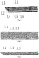
Fig. 1 is a schematic diagram ofEmbodiment 1 of the invention. -
Fig. 2 is a top view ofEmbodiment 1 of the invention. -
Fig. 3 is a schematic diagram of a first wallboard inEmbodiment 1 of the invention. -
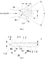
Fig. 4 is a schematic diagram of a pressure angle inEmbodiment 1 of the invention. -
Fig. 5 is a cross-sectional view ofEmbodiment 1 of the invention. -
Fig. 6 is a cross-sectional view of Embodiment 2 of the invention. -
Fig. 7 is a cross-sectional view of Embodiment 3 of the invention. -
Fig. 8 is a cross-sectional view ofEmbodiment 4 of the invention. -
Fig. 9 is a schematic diagram of Embodiment 8 of the invention. -
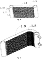
Fig. 10 is a schematic diagram of Embodiment 9 of the invention. -
Fig. 11 is a schematic diagram ofEmbodiment 10 of the invention. -
Fig. 12 is a schematic diagram of Embodiment 11 of the invention. -
Fig. 13 is a schematic diagram of Embodiment 12 of the invention. -
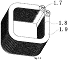
Fig. 14 is a schematic diagram of Embodiment 13 of the invention. - In the figures:
- 1.1-first wallboard, 1.2-second wallboard, 1.3-first protrusion, 1.4-second protrusion, 1.5-first turnup, 1.6-second turnup, 1.7-collection tube, 1.8-fin, 1.9-baffle plate, and 1.10-connection tube;
- 2.1-first wallboard, 2.2-second wallboard, 2.3-third protrusion, 2.4-first turnup, and 2.5-second turnup;
- 3.1-first wallboard, 3.2-second wallboard, 3.3-first protrusion, 3.4-second protrusion, and 3.5-third turnup; and
- 4.1-first wallboard, 4.2-second wallboard, 4.3-third protrusion, and 4.4-third turnup.
- The technical solutions in the embodiments of the invention are explained and described below in combination with the accompanying drawings in the embodiments of the invention. However, the following embodiments are merely preferred embodiments, rather than all embodiments, of the invention All other embodiments obtained by a person of ordinary skill in the art based on the embodiments of the invention without creative efforts shall pertain to the protection scope of the invention.
- Reference throughout this specification to "an embodiment" or "instance" or "example" means that a particular feature, structure or characteristic described in connection with the embodiment is included in at least one embodiment of the invention. The appearances of the phrase "in an embodiment" in various places throughout this specification are not necessarily referring to the same embodiment of the invention.
- In the description of the embodiments of the invention, orientation or position relationships indicated by the terms "upper", "lower", "left", "right", "horizontal", "vertical", "inner", "outer", etc. are based on the orientation or position relationships as shown in the drawings, for ease of the description of the invention only, rather than indicating that the invention must be constructed and operated in a particular orientation. Therefore, these terms should not be understood as a limitation to the invention.
- The embodiment provides a microchannel heat exchanger. As shown in
Fig. 1 to Fig. 5 , a microchannel heat exchanger includes a first wallboard 1.1 and a second wallboard 1.2 that are formed separately; and the first wallboard 1.1 and the second wallboard 1.2 are opposite to each other, with a thickness t of 0.2 mm. The first wallboard 1.1 sinks towards a direction away from the second wallboard 1.2 to form a first groove (not labeled in the figure), the second wallboard 1.2 sinks towards a direction away from the first wallboard 1.1 to form a second groove (not labeled in the figure), and the first groove and the second groove form a refrigerant circulation cavity. First protrusions 1.3 are disposed on the first wallboard 1.1. Second protrusions 1.4 are disposed on the second wallboard 1.2. Each of the first protrusions 1.3 is of a truncated cone-shaped and may also be of a strip shape and other shapes. In this embodiment, each of the first protrusions 1.3 is of the truncated cone-shaped preferably and uniformly distributed on a bottom wall of the first groove. Each of the second protrusions 1.4 is of the truncated cone-shaped, and uniformly distributed on a bottom wall of the second groove. In this embodiment, a height d of each of the first protrusions 1.3 and a height d of each of the second protrusions 1.4 are 0.3 mm. A top diameter Di of each of the first protrusions 1.3 and a top diameter Di of each of the second protrusions 1.4 are 0.8 mm-1.5 mm, and a bottom diameter Do=Di+2∗d∗tanα, where the α is a draft angle for the first protrusions 1.3 and the second protrusions 1.4. In this embodiment, the draft angle α is 10° -25° . In this way, on one hand, a problem of poor circulation of a refrigerant due to an excessively small channel in a flat tube may be prevented to improve the heat exchange efficiency; and on the other hand, by means of a reasonable design of a top diameter, a bottom diameter and a draft angle of a protrusion, a connection strength of a wallboard may be guaranteed, and thus a first protrusion and a second protrusion can bear a large pressure of the refrigerant after being connected. - In this embodiment, two sidewalls of the first groove extend out of the first groove to form two first turnups 1.5, and two sidewalls of the second groove extend out of the second groove to form two second turnups 1.6. In this embodiment, the first protrusions 1.3 and the first turnups 1.5 are formed by stamping the first wallboard 1.1, and the second protrusions 1.4 and the second turnups 1.6 are formed by stamping the second wallboard 1.2. Compared with the existing porous flat tube extruded formation, the stamping-pressing technology is simple, low in energy consumption and low in technical threshold; and a heat exchanger producer may make a selection to independently produce or purchase it, thus reducing a purchasement cost of the flat tube and improving a pricing power. Meanwhile, in different use occasions, different molds may be designed according to different working conditions to stamp the wallboard, to form the microchannel flat tube having multiple internal structures to be suitable for different demands. Compared with the existing porous flat tube extruded formation, the structure is flexible, the process is simple, and the reliability is high; and meanwhile, with the stamping formation, a bending operation turns out to be unnecessary, and the problems that the microchannel of the fat tube is easily blocked and cracked and the like in the bending operation are prevented. The first protrusions 1.3 and the second protrusions 1.4 are the same in shape, quantity and position, and the first turnups 1.5 and the second turnups 1.6 are the same in shape and position. As a result, the first wallboard 1.1 and the second wallboard 1.2 are symmetrical. The two wallboards may be machined completely just by opening a mold once. Therefore, the production step is simplified, the mold opening expense is reduced, and the production cost is saved. The first wallboard 1.1 is connected to the second wallboard 1.2, the two first turnups 1.5 are in soldering connection with the two turnups 1.6, and a top surface of each of the first protrusions 1.3 is in soldering connection with a top surface of each of the second protrusions 1.4, so the process is simple and reliable, and the sealing property is good. Meanwhile, the top surface of the first protrusions 1.3 and the top surface of the second protrusions 1.4 are abutted against each other and also in soldering connection, so that the first protrusions 1.3 and the second protrusions 1.4 may bear a high pressure of the refrigerant. By virtue of the soldering connection, the first protrusions 1.3 and the second protrusions 1.4 may be prevented from being impacted by a high-pressure refrigerant to deform. Therefore, the reliability of the flat tube is improved, and the connection strength between the first wallboard 1.1 and the second wallboard 1.2 is also enhanced.
- As shown in
Fig. 4 , there are multiple first protrusions and multiple second protrusions, an included angle formed by any of three adjacent first protrusions of the first protrusions 1.3 on the first wallboard or any of three adjacent second protrusions of the second protrusions on the second wallboard along a flow direction of the refrigerant is defined as an incoming-flow pressure angle θ,
- Additionally, a strength factor ϕ is defined to represent a pressurization behavior of a tube pass of the flat tube. The ϕ is affected by the distance Lv between two adjacent protrusions along the width direction of the wallboard, the distance Lh between two adjacent protrusions along the length direction of the wallboard, and the top diameter Di of the protrusion, specifically,

- For an assembled flat tube, on a length direction, the protrusion portions are formed by multiple first protrusions 1.3 and multiple second protrusions 1.4 by soldering connection forms multiple refrigerant channels in a refrigerant circulation cavity formed by the first groove and the second groove. As each of the first protrusions 1.3 and each of the second protrusions 1.4 are of the truncated cone-shaped, a space for allowing the refrigerant in adjacent refrigerant channels to circulate to each other forms between adjacent protrusion portions of the multiple protrusion portions. Consequently, a cavity of the flat tube is of a space structure, which is easier to implement turbulent flowing in the tube. Compared with an existing linear hole flat tube, the heat exchange in the tube may further be enhanced.
- The first protrusions 1.3 and the second protrusions 1.4 are formed by stamping, so a panel surface of the first wallboard 1.1 and a panel surface of the second wallboard 1.2 sink into the refrigerant circulation cavity to form multiple concave pits. Because of the concave pits, a plurality of channels are provided between a fin and the flat tube certainly due to incomplete welding. In a working condition of an evaporator and a heat pump, the heat exchanger tends to be installed vertically; and condensing water is gathered under the action of the gravity and flows down via the concave pit, to implement water drainage of the microchannel evaporator; and thus, the heat exchange efficiency is further improved.
- As shown in
Fig. 6 , different fromEmbodiment 1, a microchannel heat exchanger in this embodiment includes a first wallboard 2.1 and a second wallboard 2.2 that are formed separately; and the first wallboard 2.1 and the second wallboard 2.2 are opposite to each other. In this embodiment, the first wallboard 2.1 and the second wallboard 2.2 have a thickness t of 0.2 mm. The first wallboard 2.1 sinks towards a direction away from the second wallboard 1.2 to form a first groove, the second wallboard 2.2 sinks towards a direction away from the first wallboard 2.1 to form a second groove, and the first groove and the second groove form a refrigerant circulation cavity. Multiple third protrusions 2.3 are disposed on the first wallboard 2.1. Each of the third protrusions 2.3 is of a truncated cone-shaped and is uniformly distributed on a bottom wall of the first groove. In this embodiment, a height d of each of the third protrusions 2.3 is 0.5 mm. Two sidewalls of the first groove extend out of the first groove to form two first turnups 2.4, and two sidewalls of the second groove extend out of the second groove to form two second turnups 2.5. In this embodiment, the third protrusions 2.3 and the two first turnups 2.4 are formed by stamping the first wallboard 2.1, the second turnups 2.5 are formed by stamping the second wallboard 2.2, the two first turnups 2.4 are in soldering connection with the two second turnups 2.5, and a top surface of each of the third protrusion 2.3 is in soldering connection with a plate surface of the second wallboard 2.2. - As shown in
Fig. 7 , different fromEmbodiment 1, a microchannel heat exchanger in this embodiment includes a first wallboard 3.1 and a second wallboard 3.2 that are formed separately; and the first wallboard 3.1 and the second wallboard 3.2 are opposite to each other. In this embodiment, the first wallboard 3.1 and the second wallboard 3.2 have a thickness t of 0.8mm. The first wallboard 3.1 sinks towards a direction away from the second wallboard 3.2 to form a first groove, the second wallboard 3.2 is a flat plate, multiple first protrusions 3.3 are disposed on the first wallboard 3.1, multiple second protrusions 3.4 are disposed on the second wallboard 3.2, each of the first protrusion 3.3 is of a truncated cone-shaped and is uniformly distributed on a bottom wall of the first groove, each of the second protrusion 3.4 is also of the truncated cone-shaped, and each of the second protrusion 3.4 and each of the first protrusion 3.3 are the same in shape, quantity and position. In this embodiment, a height d of each of the first protrusions 3.3 and a height d of each of the second protrusions 3.4 are 1.0 mm. Two sidewalls of the first groove extend out of the first groove to form two third turnups 3.5. In this embodiment, the first protrusions 3.3 and the third turnups 3.5 are formed by stamping the first wallboard 3.1, the second protrusions 3.4 are formed by stamping the second wallboard 1.2, the third turnups 3.5 are directly in soldering connection with a plate surface of the second wallboard 3.2, and a top surface of the first protrusions 3.3 are in soldering connection with a top surface of the second protrusions 3.4. - As shown in
Fig. 8 , different fromEmbodiment 1, a microchannel heat exchanger in this embodiment includes a first wallboard 4.1 and a second wallboard 4.2 that are formed separately; and the first wallboard 4.1 and the second wallboard 4.2 are opposite to each other. In this embodiment, a thickness t of the first wallboard 4.1 and a thickness t of the second wallboard 4.2 are 0.6mm. The first wallboard 4.1 sinks towards a direction away from the second wallboard 4.2 to form a first groove. The second wallboard 4.2 is a flat plate. Multiple third protrusions 4.3 are disposed on the first wallboard 4.1. Each of the third protrusions 4.3 is of a truncated cone-shaped and is uniformly distributed on a bottom wall of the first groove. In this embodiment, a height d of each of the third protrusions 4.3 is 1.2mm. Two sidewalls of the first groove extend out of the first groove to form two third turnups 4.4. In this embodiment, the third protrusions 4.3 and the third turnups 4.4 are formed by stamping the first wallboard 4.1, the third turnups 4.4 are directly in soldering connection with a plate surface of the second wallboard 4.2, and a top surface of each of the third protrusions 4.3 is in soldering connection with a plate surface of the second wallboard 4.2. - Different from
Embodiment 1, in this embodiment, a thickness of a first wallboard and a thickness of a second wallboard are 0.4 mm; multiple first protrusions are disposed on the first wallboard; multiple second protrusion are disposed on the second wallboard; both each of the first protrusions and each of the second protrusions are of a truncated cone-shaped; a height of each of the first protrusions is 1.0 mm, with a top surface of each of the first protrusions in soldering connection with the second wallboard; a height of each of the second protrusion is 1.0 mm, with a top surface of each of the second protrusions in soldering connection with the first wallboard; and the first protrusions and the second protrusions are arranged in a staggered manner, to form multiple refrigerant channels arranged along a length direction of a flat tube. - Different from
Embodiment 1, in this embodiment, a thickness of a first wallboard and a thickness of a second wallboard are 0.5 mm, and a height of each of multiple first protrusions and a height of each of multiple second protrusions are 0.8 mm. A sidewall of the first groove and a sidewall of the second groove are at least partially overlapped to each other, and an overlapped portion is fixed by soldering connection. - Different from Embodiment 2, in this embodiment, a thickness of a first wallboard and a thickness of a second wallboard are 0.5 mm, and a height of each of multiple third protrusions is 1.0 mm.
- As shown in
Fig. 9 , the embodiment provides a microchannel heat exchanger, including two collection tubes 1.7; multiple connection tubes 1.10 connected to a refrigeration system are disposed on one collection tube 1.7; multiple flat tubes described inEmbodiment 1 are connected between the two collection tubes 1.7; a wavy fin 1.8 is disposed between adjacent flat tubes to increase a heat dissipation area; and meanwhile, the fin 1.8 is also disposed on outside surfaces of two flat tubes located on end portions of the collection tubes 1.7, and the fin 1.8 herein is protected by a baffle plate 1.9 to prevent deformation and damage of the fin 1.8. The microchannel heat exchanger in this embodiment is of a straight panel shape. - As shown in
Fig. 10 , different from Embodiment 8, a microchannel heat exchanger in this embodiment is of an L shape. The L-shaped microchannel heat exchanger is formed by bending a flat tube and a baffle plate 1.9 on a length direction. A fin 1.8 is disposed between the flat tube and the flat tube as well as between the flat tube and the baffle plate 1.9. - As shown in
Fig. 11 , different from Embodiment 8, a microchannel heat exchanger in this embodiment is of a U shape. The U-shaped microchannel heat exchanger is formed by bending a flat tube and a baffle plate 1.9 on a length direction. A fin 1.8 is disposed between the flat tube and the flat tube as well as between the flat tube and the baffle plate 1.9. - As shown in
Fig. 12 , different from Embodiment 8, a microchannel heat exchanger in this embodiment is of a V shape. The V-shaped microchannel heat exchanger is formed by bending a flat tube and a baffle plate 1.9 on a length direction. A fin 1.8 is disposed between the flat tube and the flat tube as well as between the flat tube and the baffle plate 1.9. - As shown in
Fig. 13 , different from Embodiment 8, a microchannel heat exchanger in this embodiment is of a circular shape. The circular microchannel heat exchanger is formed by bending a flat tube and a baffle plate 1.9 on a length direction. Two collection tubes of the microchannel heat exchanger are abutted against each other to form a closed loop. A fin 1.8 is disposed between the flat tube and the flat tube as well as between the flat tube and the baffle plate 1.9. - As shown in
Fig. 14 , different from Embodiment 8, a microchannel heat exchanger in this embodiment is of a square shape. The square microchannel heat exchanger is formed by bending a flat tube and a baffle plate 1.9 on a length direction. Two collection tubes of the microchannel heat exchanger are abutted against each other to form a closed loop. A fin 1.8 is disposed between the flat tube and the flat tube as well as between the flat tube and the baffle plate 1.9. - The above are merely specific embodiments of the invention, and the protection scope of the present invention is not limited thereto. It should be understood by the person skilled in the art that the invention includes but not limited to the accompanying drawings and the content described in the specific embodiments. Any modification without departing from a function and a structural principle of the invention is included in the scope of the claims.
Claims (18)
- A flat tube for a microchannel heat exchanger, comprising a first wallboard and a second wallboard that are formed separately, wherein the first wallboard is connected to the second wallboard to form a refrigerant circulation cavity, and the first wallboard and/or the second wallboard have/has a plurality of protrusion portions protruding into the refrigerant circulation cavity to form multiple refrigerant channels, arranged along a length direction of the flat tube, in the refrigerant circulation cavity.
- The flat tube as claimed in claim 1, wherein the protrusion portions comprises a first protrusion and a second protrusion, the first protrusion protrudes from the first wallboard to the second wallboard, the second protrusion protrudes from the second wallboard to the first wallboard, and the first protrusion and the second protrusion are abutted against each other and connected; or the protrusion portions comprises a first protrusion and a second protrusion, the first protrusion protrudes from the first wallboard to the second wallboard, the second protrusion protrudes from the second wallboard to the first wallboard, the first protrusion is connected to the second wallboard, the second protrusion is connected to the first wallboard, and the first protrusion and the second protrusion are distributed in a staggered manner.
- The flat tube as claimed in claim 2, wherein the first wallboard is recessed into the refrigerant circulation cavity to form the first protrusion, the second wallboard is recessed into the refrigerant circulation cavity to form the second protrusion, and the first protrusion and the second protrusion are 0.3 mm-1.0 mm high.
- The flat tube as claimed in claim 3, wherein the first wallboard and the second wallboard are the same in structure.
- The flat tube as claimed in claim 1, wherein the protrusion portions protrudes from the first wallboard to the second wallboard, and the protrusion portions is connected to the second wallboard; or the protrusion portions protrudes from the second wallboard to the first wallboard, and the protrusion portions is connected to the first wallboard.
- The flat tube as claimed in claim 5, wherein the protrusion portions is formed by recessing the first wallboard into the refrigerant circulation cavity; or the protrusion portions is formed by recessing the second wallboard into the refrigerant circulation cavity, and the protrusion portions is 0.5 mm-1.2 mm high.
- The flat tube as claimed in claim 2 or 5, wherein there are multiple first protrusions and multiple second protrusions, any of three adjacent first protrusions of the multiple first protrusions on the first wallboard or any of three adjacent second protrusions of the multiple second protrusions on the second wallboard form an included angle

- The flat tube as claimed in claim 7, wherein the included angle θ is 60°-150°.
- The flat tube as claimed in claim 1, wherein when the protrusion portions is of a truncated cone-shaped, a top diameter Di of the protrusion portions and a bottom diameter Do of the protrusion portions meet: Do=Di+2∗d∗tanα, the α being a draft angle of the protrusion portions.
- The flat tube as claimed in claim 9, wherein the draft angle is 10°-25°.
- The flat tube as claimed in claim 1, wherein there are multiple protrusion portions, the multiple protrusion portions are distributed at intervals along a length direction of the flat tube in the refrigerant circulation cavity, so as to form, between adjacent protrusion portions of the multiple protrusion portions, a space for allowing mutual circulation of a refrigerant in adjacent refrigerant channels.
- The flat tube as claimed in any one of claims 1 to 6, wherein the first wallboard has a first groove sinking towards a direction away from the second wallboard, the second wallboard has a second groove sinking towards a direction away from the first wallboard, and a sidewall of the first groove is connected to a sidewall of the second groove to form the refrigerant circulation cavity.
- The flat tube as claimed in claim 12, wherein the sidewall of the first groove extends out of the first groove to form a first turnup, the sidewall of the second groove extends out of the second groove to form a second turnup, and the first turnup and the second turnup are connected to each other.
- The flat tube as claimed in claim 13, wherein the sidewall of the first groove and the sidewall of the second groove are at least partially overlapped to each other, and an overlapped portion is fixed by welding.
- The flat tube as claimed in any one of claims 1 to 6, wherein the first wallboard has a groove sinking towards a direction away from the second wallboard, a sidewall of the groove extends out of the groove to form a turnup, and the turnup is connected to the second wallboard; or the second wallboard has a groove sinking towards a direction away from the first wallboard, a sidewall of the groove extends out of the groove to form a turnup, and the turnup is connected to the first wallboard.
- The flat tube as claimed in claim 1, wherein a thickness of the first wallboard and a thickness of the second wallboard are 0.2 mm-0.8 mm.
- A microchannel heat exchanger, comprising the flat tube as claimed in any one of claims 1 to 16.
- The microchannel heat exchanger as claimed in claim 17, wherein the microchannel heat exchanger is of a straight panel shape, a circular shape, a square shape, an L shape, a U shape or a V shape.
Applications Claiming Priority (2)
| Application Number | Priority Date | Filing Date | Title |
|---|---|---|---|
| CN201710866253.0A CN109539852A (en) | 2017-09-22 | 2017-09-22 | A kind of flat tube and micro-channel heat exchanger of micro-channel heat exchanger |
| PCT/CN2018/104483 WO2019056951A1 (en) | 2017-09-22 | 2018-09-07 | Flat tube for microchannel heat exchanger, and microchannel heat exchanger |
Publications (3)
| Publication Number | Publication Date |
|---|---|
| EP3677865A1 true EP3677865A1 (en) | 2020-07-08 |
| EP3677865A4 EP3677865A4 (en) | 2021-06-02 |
| EP3677865B1 EP3677865B1 (en) | 2024-11-06 |
Family
ID=65810106
Family Applications (1)
| Application Number | Title | Priority Date | Filing Date |
|---|---|---|---|
| EP18858124.3A Active EP3677865B1 (en) | 2017-09-22 | 2018-09-07 | Flat tube for microchannel heat exchanger, and microchannel heat exchanger |
Country Status (7)
| Country | Link |
|---|---|
| US (1) | US20200256624A1 (en) |
| EP (1) | EP3677865B1 (en) |
| JP (1) | JP2020537103A (en) |
| KR (1) | KR20200044882A (en) |
| CN (1) | CN109539852A (en) |
| ES (1) | ES2996358T3 (en) |
| WO (1) | WO2019056951A1 (en) |
Families Citing this family (9)
| Publication number | Priority date | Publication date | Assignee | Title |
|---|---|---|---|---|
| JP1615542S (en) * | 2017-08-21 | 2018-10-09 | ||
| CN111912280A (en) * | 2019-05-09 | 2020-11-10 | 浙江盾安热工科技有限公司 | Flat pipe, heat exchanger and heat pump water heater |
| JP7263970B2 (en) * | 2019-08-06 | 2023-04-25 | 株式会社デンソー | Heat exchanger |
| CN112762731A (en) * | 2019-10-21 | 2021-05-07 | 浙江盾安热工科技有限公司 | Flat pipe, micro-channel heat exchanger and air conditioner |
| JP7436790B2 (en) * | 2019-11-01 | 2024-02-22 | ダイキン工業株式会社 | Plate type refrigerant piping and refrigeration equipment |
| CN113310340B (en) * | 2020-02-27 | 2025-04-08 | 浙江盾安热工科技有限公司 | Heat Exchanger |
| CN214582724U (en) * | 2021-02-05 | 2021-11-02 | 杭州三花微通道换热器有限公司 | Heat exchange tube and heat exchanger with same |
| CN112944972A (en) * | 2021-02-09 | 2021-06-11 | 广东鑫统仕集团有限公司 | Dotting radiating tube |
| CN222824890U (en) * | 2024-01-29 | 2025-05-02 | 杭州三花微通道换热器有限公司 | Heat exchange tube and heat exchanger having the same |
Family Cites Families (22)
| Publication number | Priority date | Publication date | Assignee | Title |
|---|---|---|---|---|
| JPH0228981U (en) * | 1988-08-12 | 1990-02-23 | ||
| JPH073181Y2 (en) * | 1988-08-12 | 1995-01-30 | カルソニック株式会社 | Multi-flow type heat exchanger |
| JPH0719774A (en) * | 1993-06-30 | 1995-01-20 | Zexel Corp | Flat tube of heat exchanger |
| JPH08200977A (en) * | 1995-01-27 | 1996-08-09 | Zexel Corp | Flat tube for heat exchanger and manufacture thereof |
| JPH09310989A (en) * | 1996-05-23 | 1997-12-02 | Calsonic Corp | Heat exchanger |
| JPH1019494A (en) * | 1996-07-05 | 1998-01-23 | Zexel Corp | Flat tube for heat exchanger |
| JPH1085879A (en) * | 1996-09-17 | 1998-04-07 | Nippon Light Metal Co Ltd | Bending method of finned heat exchanger and finned heat exchanger |
| JPH11294990A (en) * | 1998-04-06 | 1999-10-29 | Zexel:Kk | Juxtaposed integrated heat exchanger |
| JP4018280B2 (en) * | 1999-01-19 | 2007-12-05 | カルソニックカンセイ株式会社 | Flat tube for heat exchanger |
| EP1022532A3 (en) * | 1999-01-19 | 2001-08-01 | Calsonic Kansei Corporation | Flat tubes for use with heat exchanger and manufacturing method thereof |
| JP2004003855A (en) * | 2003-08-06 | 2004-01-08 | Zexel Valeo Climate Control Corp | Flat tube for heat exchanger, and its manufacturing method |
| JP2006266528A (en) * | 2005-03-22 | 2006-10-05 | T Rad Co Ltd | Flat tube for heat exchanger |
| JP2007278558A (en) * | 2006-04-04 | 2007-10-25 | Denso Corp | Refrigerant radiator |
| CN101589286B (en) * | 2007-01-23 | 2011-09-28 | 摩丁制造公司 | Heat exchanger and method |
| JP2009162426A (en) * | 2008-01-07 | 2009-07-23 | Denso Corp | Heat exchanger |
| EP2306134B1 (en) * | 2009-10-01 | 2012-05-30 | Techspace Aero S.A. | Method for manufacturing a heat exchanger element and exchanger obtained using the method |
| CN102079038B (en) * | 2010-12-08 | 2013-02-13 | 三花控股集团有限公司 | Heat exchanger and refrigerant diversion tube thereof as well as method for processing refrigerant diversion tube |
| JP5589860B2 (en) * | 2011-01-17 | 2014-09-17 | 株式会社デンソー | Heat exchanger |
| KR20150126386A (en) * | 2013-03-01 | 2015-11-11 | 사파 에이에스 | Multi port extrusion (mpe) design |
| CN104167399B (en) * | 2014-05-14 | 2017-09-01 | 北京工业大学 | The complicated microchannel micro heat exchanger of dislocation |
| CN106767090A (en) * | 2016-12-07 | 2017-05-31 | 泰安福星汽车配件有限公司 | A kind of reinforced radiating tube and processing technology |
| CN106885487A (en) * | 2017-03-28 | 2017-06-23 | 珠海格力电器股份有限公司 | Water tank heat exchanger and water heater |
-
2017
- 2017-09-22 CN CN201710866253.0A patent/CN109539852A/en active Pending
-
2018
- 2018-09-07 WO PCT/CN2018/104483 patent/WO2019056951A1/en not_active Ceased
- 2018-09-07 ES ES18858124T patent/ES2996358T3/en active Active
- 2018-09-07 KR KR1020207008465A patent/KR20200044882A/en not_active Ceased
- 2018-09-07 JP JP2020514290A patent/JP2020537103A/en active Pending
- 2018-09-07 EP EP18858124.3A patent/EP3677865B1/en active Active
- 2018-09-07 US US16/649,150 patent/US20200256624A1/en not_active Abandoned
Also Published As
| Publication number | Publication date |
|---|---|
| WO2019056951A1 (en) | 2019-03-28 |
| KR20200044882A (en) | 2020-04-29 |
| EP3677865B1 (en) | 2024-11-06 |
| CN109539852A (en) | 2019-03-29 |
| JP2020537103A (en) | 2020-12-17 |
| US20200256624A1 (en) | 2020-08-13 |
| ES2996358T3 (en) | 2025-02-12 |
| EP3677865A4 (en) | 2021-06-02 |
Similar Documents
| Publication | Publication Date | Title |
|---|---|---|
| EP3677865A1 (en) | Flat tube for microchannel heat exchanger, and microchannel heat exchanger | |
| US7762318B2 (en) | Condensing heat-exchange copper tube for an flooded type electrical refrigeration unit | |
| CN107782192B (en) | A kind of evaporation and condensation dual-purpose ladder grid internal and external fin tube | |
| CN104864634A (en) | Flat pipe plate-fin easy-drainage microchannel evaporator for inter-cooled refrigerator | |
| CN105823364A (en) | Radiating fin and production process thereof | |
| CN104864635A (en) | Flat tube fin penetrating type micro-channel evaporator for direct-cooling refrigerator | |
| JPS6151238B2 (en) | ||
| EP4425082A1 (en) | Micro-channel heat exchanger | |
| CN204227766U (en) | A kind of C type hair fin condenser | |
| CN204757465U (en) | Little channel evaporator of easy drainage of piece formula is worn with flat pipe to intercooling refrigerator | |
| CN212566999U (en) | Primary surface type heat exchanger core | |
| CN2745021Y (en) | Reinforced heat transfer tube with discontinuous staggered arrangement inner ribs | |
| JP2003148890A (en) | Heat exchanger tube and its manufacturing method | |
| CN105258400A (en) | Coaxial threaded pipe leakage flow type heat exchanger | |
| CN104949398A (en) | Indirect cooling refrigerator micro-channel evaporator with flat tubes penetrating through cooling fins | |
| CN204757467U (en) | Piece channel evaporator that declines is worn with flat pipe to intercooling refrigerator | |
| CN204885134U (en) | A high-efficiency heat sink | |
| CN204142068U (en) | A kind of combined hot exchanges flat tube | |
| CN222260008U (en) | A hollow thin sheet metal heat sink | |
| CN216745611U (en) | Seven hole type parallel flow heat transfer aluminum flat tube of narrow distance | |
| CN206247931U (en) | A heat exchange tube and a heat exchanger having the same | |
| CN204757466U (en) | Piece channel evaporator that declines is worn with flat pipe to direct -cooled refrigerator | |
| CN217636941U (en) | Enhanced heat dissipation water pipe | |
| CN207795389U (en) | A kind of engine radiating band | |
| CN204064081U (en) | A kind of Internal Screw Thread Heat Exchange Pipes |
Legal Events
| Date | Code | Title | Description |
|---|---|---|---|
| STAA | Information on the status of an ep patent application or granted ep patent |
Free format text: STATUS: THE INTERNATIONAL PUBLICATION HAS BEEN MADE |
|
| PUAI | Public reference made under article 153(3) epc to a published international application that has entered the european phase |
Free format text: ORIGINAL CODE: 0009012 |
|
| STAA | Information on the status of an ep patent application or granted ep patent |
Free format text: STATUS: REQUEST FOR EXAMINATION WAS MADE |
|
| 17P | Request for examination filed |
Effective date: 20200331 |
|
| AK | Designated contracting states |
Kind code of ref document: A1 Designated state(s): AL AT BE BG CH CY CZ DE DK EE ES FI FR GB GR HR HU IE IS IT LI LT LU LV MC MK MT NL NO PL PT RO RS SE SI SK SM TR |
|
| AX | Request for extension of the european patent |
Extension state: BA ME |
|
| DAV | Request for validation of the european patent (deleted) | ||
| DAX | Request for extension of the european patent (deleted) | ||
| A4 | Supplementary search report drawn up and despatched |
Effective date: 20210430 |
|
| RIC1 | Information provided on ipc code assigned before grant |
Ipc: F28F 1/02 20060101AFI20210423BHEP |
|
| STAA | Information on the status of an ep patent application or granted ep patent |
Free format text: STATUS: EXAMINATION IS IN PROGRESS |
|
| 17Q | First examination report despatched |
Effective date: 20230824 |
|
| GRAP | Despatch of communication of intention to grant a patent |
Free format text: ORIGINAL CODE: EPIDOSNIGR1 |
|
| STAA | Information on the status of an ep patent application or granted ep patent |
Free format text: STATUS: GRANT OF PATENT IS INTENDED |
|
| INTG | Intention to grant announced |
Effective date: 20240607 |
|
| GRAS | Grant fee paid |
Free format text: ORIGINAL CODE: EPIDOSNIGR3 |
|
| GRAA | (expected) grant |
Free format text: ORIGINAL CODE: 0009210 |
|
| STAA | Information on the status of an ep patent application or granted ep patent |
Free format text: STATUS: THE PATENT HAS BEEN GRANTED |
|
| AK | Designated contracting states |
Kind code of ref document: B1 Designated state(s): AL AT BE BG CH CY CZ DE DK EE ES FI FR GB GR HR HU IE IS IT LI LT LU LV MC MK MT NL NO PL PT RO RS SE SI SK SM TR |
|
| REG | Reference to a national code |
Ref country code: GB Ref legal event code: FG4D |
|
| REG | Reference to a national code |
Ref country code: CH Ref legal event code: EP |
|
| P01 | Opt-out of the competence of the unified patent court (upc) registered |
Free format text: CASE NUMBER: APP_57329/2024 Effective date: 20241021 |
|
| REG | Reference to a national code |
Ref country code: DE Ref legal event code: R096 Ref document number: 602018076379 Country of ref document: DE |
|
| REG | Reference to a national code |
Ref country code: IE Ref legal event code: FG4D |
|
| REG | Reference to a national code |
Ref country code: ES Ref legal event code: FG2A Ref document number: 2996358 Country of ref document: ES Kind code of ref document: T3 Effective date: 20250212 |
|
| REG | Reference to a national code |
Ref country code: LT Ref legal event code: MG9D |
|
| REG | Reference to a national code |
Ref country code: NL Ref legal event code: MP Effective date: 20241106 |
|
| PG25 | Lapsed in a contracting state [announced via postgrant information from national office to epo] |
Ref country code: HR Free format text: LAPSE BECAUSE OF FAILURE TO SUBMIT A TRANSLATION OF THE DESCRIPTION OR TO PAY THE FEE WITHIN THE PRESCRIBED TIME-LIMIT Effective date: 20241106 Ref country code: PT Free format text: LAPSE BECAUSE OF FAILURE TO SUBMIT A TRANSLATION OF THE DESCRIPTION OR TO PAY THE FEE WITHIN THE PRESCRIBED TIME-LIMIT Effective date: 20250306 Ref country code: IS Free format text: LAPSE BECAUSE OF FAILURE TO SUBMIT A TRANSLATION OF THE DESCRIPTION OR TO PAY THE FEE WITHIN THE PRESCRIBED TIME-LIMIT Effective date: 20250306 |
|
| PG25 | Lapsed in a contracting state [announced via postgrant information from national office to epo] |
Ref country code: FI Free format text: LAPSE BECAUSE OF FAILURE TO SUBMIT A TRANSLATION OF THE DESCRIPTION OR TO PAY THE FEE WITHIN THE PRESCRIBED TIME-LIMIT Effective date: 20241106 Ref country code: NL Free format text: LAPSE BECAUSE OF FAILURE TO SUBMIT A TRANSLATION OF THE DESCRIPTION OR TO PAY THE FEE WITHIN THE PRESCRIBED TIME-LIMIT Effective date: 20241106 |
|
| REG | Reference to a national code |
Ref country code: AT Ref legal event code: MK05 Ref document number: 1739750 Country of ref document: AT Kind code of ref document: T Effective date: 20241106 |
|
| PG25 | Lapsed in a contracting state [announced via postgrant information from national office to epo] |
Ref country code: BG Free format text: LAPSE BECAUSE OF FAILURE TO SUBMIT A TRANSLATION OF THE DESCRIPTION OR TO PAY THE FEE WITHIN THE PRESCRIBED TIME-LIMIT Effective date: 20241106 |
|
| PG25 | Lapsed in a contracting state [announced via postgrant information from national office to epo] |
Ref country code: NO Free format text: LAPSE BECAUSE OF FAILURE TO SUBMIT A TRANSLATION OF THE DESCRIPTION OR TO PAY THE FEE WITHIN THE PRESCRIBED TIME-LIMIT Effective date: 20250206 |
|
| PG25 | Lapsed in a contracting state [announced via postgrant information from national office to epo] |
Ref country code: GR Free format text: LAPSE BECAUSE OF FAILURE TO SUBMIT A TRANSLATION OF THE DESCRIPTION OR TO PAY THE FEE WITHIN THE PRESCRIBED TIME-LIMIT Effective date: 20250207 Ref country code: LV Free format text: LAPSE BECAUSE OF FAILURE TO SUBMIT A TRANSLATION OF THE DESCRIPTION OR TO PAY THE FEE WITHIN THE PRESCRIBED TIME-LIMIT Effective date: 20241106 Ref country code: AT Free format text: LAPSE BECAUSE OF FAILURE TO SUBMIT A TRANSLATION OF THE DESCRIPTION OR TO PAY THE FEE WITHIN THE PRESCRIBED TIME-LIMIT Effective date: 20241106 |
|
| PG25 | Lapsed in a contracting state [announced via postgrant information from national office to epo] |
Ref country code: PL Free format text: LAPSE BECAUSE OF FAILURE TO SUBMIT A TRANSLATION OF THE DESCRIPTION OR TO PAY THE FEE WITHIN THE PRESCRIBED TIME-LIMIT Effective date: 20241106 |
|
| PG25 | Lapsed in a contracting state [announced via postgrant information from national office to epo] |
Ref country code: RS Free format text: LAPSE BECAUSE OF FAILURE TO SUBMIT A TRANSLATION OF THE DESCRIPTION OR TO PAY THE FEE WITHIN THE PRESCRIBED TIME-LIMIT Effective date: 20250206 |
|
| PG25 | Lapsed in a contracting state [announced via postgrant information from national office to epo] |
Ref country code: SM Free format text: LAPSE BECAUSE OF FAILURE TO SUBMIT A TRANSLATION OF THE DESCRIPTION OR TO PAY THE FEE WITHIN THE PRESCRIBED TIME-LIMIT Effective date: 20241106 |
|
| PG25 | Lapsed in a contracting state [announced via postgrant information from national office to epo] |
Ref country code: DK Free format text: LAPSE BECAUSE OF FAILURE TO SUBMIT A TRANSLATION OF THE DESCRIPTION OR TO PAY THE FEE WITHIN THE PRESCRIBED TIME-LIMIT Effective date: 20241106 |
|
| PG25 | Lapsed in a contracting state [announced via postgrant information from national office to epo] |
Ref country code: EE Free format text: LAPSE BECAUSE OF FAILURE TO SUBMIT A TRANSLATION OF THE DESCRIPTION OR TO PAY THE FEE WITHIN THE PRESCRIBED TIME-LIMIT Effective date: 20241106 |
|
| PG25 | Lapsed in a contracting state [announced via postgrant information from national office to epo] |
Ref country code: RO Free format text: LAPSE BECAUSE OF FAILURE TO SUBMIT A TRANSLATION OF THE DESCRIPTION OR TO PAY THE FEE WITHIN THE PRESCRIBED TIME-LIMIT Effective date: 20241106 |
|
| PG25 | Lapsed in a contracting state [announced via postgrant information from national office to epo] |
Ref country code: SK Free format text: LAPSE BECAUSE OF FAILURE TO SUBMIT A TRANSLATION OF THE DESCRIPTION OR TO PAY THE FEE WITHIN THE PRESCRIBED TIME-LIMIT Effective date: 20241106 |
|
| PG25 | Lapsed in a contracting state [announced via postgrant information from national office to epo] |
Ref country code: CZ Free format text: LAPSE BECAUSE OF FAILURE TO SUBMIT A TRANSLATION OF THE DESCRIPTION OR TO PAY THE FEE WITHIN THE PRESCRIBED TIME-LIMIT Effective date: 20241106 |
|
| REG | Reference to a national code |
Ref country code: DE Ref legal event code: R097 Ref document number: 602018076379 Country of ref document: DE |
|
| PG25 | Lapsed in a contracting state [announced via postgrant information from national office to epo] |
Ref country code: SE Free format text: LAPSE BECAUSE OF FAILURE TO SUBMIT A TRANSLATION OF THE DESCRIPTION OR TO PAY THE FEE WITHIN THE PRESCRIBED TIME-LIMIT Effective date: 20241106 |
|
| PLBE | No opposition filed within time limit |
Free format text: ORIGINAL CODE: 0009261 |
|
| STAA | Information on the status of an ep patent application or granted ep patent |
Free format text: STATUS: NO OPPOSITION FILED WITHIN TIME LIMIT |
|
| 26N | No opposition filed |
Effective date: 20250807 |
|
| PGFP | Annual fee paid to national office [announced via postgrant information from national office to epo] |
Ref country code: FR Payment date: 20250929 Year of fee payment: 8 |
|
| PGFP | Annual fee paid to national office [announced via postgrant information from national office to epo] |
Ref country code: DE Payment date: 20251029 Year of fee payment: 8 |
|
| PGFP | Annual fee paid to national office [announced via postgrant information from national office to epo] |
Ref country code: IT Payment date: 20250929 Year of fee payment: 8 |
|
| PGFP | Annual fee paid to national office [announced via postgrant information from national office to epo] |
Ref country code: ES Payment date: 20251210 Year of fee payment: 8 |