EP3677852A1 - Control method and apparatus for self-cleaning of air conditioner, and air conditioner - Google Patents
Control method and apparatus for self-cleaning of air conditioner, and air conditioner Download PDFInfo
- Publication number
- EP3677852A1 EP3677852A1 EP17923844.9A EP17923844A EP3677852A1 EP 3677852 A1 EP3677852 A1 EP 3677852A1 EP 17923844 A EP17923844 A EP 17923844A EP 3677852 A1 EP3677852 A1 EP 3677852A1
- Authority
- EP
- European Patent Office
- Prior art keywords
- temperature
- indoor
- compressor
- operating frequency
- rotational speed
- Prior art date
- Legal status (The legal status is an assumption and is not a legal conclusion. Google has not performed a legal analysis and makes no representation as to the accuracy of the status listed.)
- Granted
Links
Images

Classifications
-
- F—MECHANICAL ENGINEERING; LIGHTING; HEATING; WEAPONS; BLASTING
- F24—HEATING; RANGES; VENTILATING
- F24F—AIR-CONDITIONING; AIR-HUMIDIFICATION; VENTILATION; USE OF AIR CURRENTS FOR SCREENING
- F24F11/00—Control or safety arrangements
- F24F11/70—Control systems characterised by their outputs; Constructional details thereof
- F24F11/72—Control systems characterised by their outputs; Constructional details thereof for controlling the supply of treated air, e.g. its pressure
- F24F11/74—Control systems characterised by their outputs; Constructional details thereof for controlling the supply of treated air, e.g. its pressure for controlling air flow rate or air velocity
- F24F11/77—Control systems characterised by their outputs; Constructional details thereof for controlling the supply of treated air, e.g. its pressure for controlling air flow rate or air velocity by controlling the speed of ventilators
-
- F—MECHANICAL ENGINEERING; LIGHTING; HEATING; WEAPONS; BLASTING
- F24—HEATING; RANGES; VENTILATING
- F24F—AIR-CONDITIONING; AIR-HUMIDIFICATION; VENTILATION; USE OF AIR CURRENTS FOR SCREENING
- F24F11/00—Control or safety arrangements
- F24F11/70—Control systems characterised by their outputs; Constructional details thereof
- F24F11/80—Control systems characterised by their outputs; Constructional details thereof for controlling the temperature of the supplied air
- F24F11/86—Control systems characterised by their outputs; Constructional details thereof for controlling the temperature of the supplied air by controlling compressors within refrigeration or heat pump circuits
-
- F—MECHANICAL ENGINEERING; LIGHTING; HEATING; WEAPONS; BLASTING
- F24—HEATING; RANGES; VENTILATING
- F24F—AIR-CONDITIONING; AIR-HUMIDIFICATION; VENTILATION; USE OF AIR CURRENTS FOR SCREENING
- F24F11/00—Control or safety arrangements
- F24F11/62—Control or safety arrangements characterised by the type of control or by internal processing, e.g. using fuzzy logic, adaptive control or estimation of values
- F24F11/63—Electronic processing
- F24F11/65—Electronic processing for selecting an operating mode
- F24F11/66—Sleep mode
-
- F—MECHANICAL ENGINEERING; LIGHTING; HEATING; WEAPONS; BLASTING
- F24—HEATING; RANGES; VENTILATING
- F24F—AIR-CONDITIONING; AIR-HUMIDIFICATION; VENTILATION; USE OF AIR CURRENTS FOR SCREENING
- F24F2110/00—Control inputs relating to air properties
- F24F2110/10—Temperature
-
- F—MECHANICAL ENGINEERING; LIGHTING; HEATING; WEAPONS; BLASTING
- F24—HEATING; RANGES; VENTILATING
- F24F—AIR-CONDITIONING; AIR-HUMIDIFICATION; VENTILATION; USE OF AIR CURRENTS FOR SCREENING
- F24F2110/00—Control inputs relating to air properties
- F24F2110/20—Humidity
-
- F—MECHANICAL ENGINEERING; LIGHTING; HEATING; WEAPONS; BLASTING
- F24—HEATING; RANGES; VENTILATING
- F24F—AIR-CONDITIONING; AIR-HUMIDIFICATION; VENTILATION; USE OF AIR CURRENTS FOR SCREENING
- F24F2140/00—Control inputs relating to system states
- F24F2140/40—Damper positions, e.g. open or closed
-
- Y—GENERAL TAGGING OF NEW TECHNOLOGICAL DEVELOPMENTS; GENERAL TAGGING OF CROSS-SECTIONAL TECHNOLOGIES SPANNING OVER SEVERAL SECTIONS OF THE IPC; TECHNICAL SUBJECTS COVERED BY FORMER USPC CROSS-REFERENCE ART COLLECTIONS [XRACs] AND DIGESTS
- Y02—TECHNOLOGIES OR APPLICATIONS FOR MITIGATION OR ADAPTATION AGAINST CLIMATE CHANGE
- Y02B—CLIMATE CHANGE MITIGATION TECHNOLOGIES RELATED TO BUILDINGS, e.g. HOUSING, HOUSE APPLIANCES OR RELATED END-USER APPLICATIONS
- Y02B30/00—Energy efficient heating, ventilation or air conditioning [HVAC]
- Y02B30/70—Efficient control or regulation technologies, e.g. for control of refrigerant flow, motor or heating
Definitions
- the present disclosure relates to the field of air conditioner technologies, and more particularly, to a method and a device for controlling self-cleaning of an air conditioner, and an air conditioner.
- Embodiments of the present disclosure provide a method and a device for controlling self-cleaning of an air conditioner, and an air conditioner, which aim to solve the problem that existing air conditioners cannot balance an indoor temperature and humidity adjustment.
- a brief summary is given below. The summary is not a general comment, nor tends to determine key/critical constituent elements or describe a protection scope of these embodiments, and only aims to present some concepts in a simplified form as an introduction of the following detailed description.
- a method for controlling an air conditioner including: when the air conditioner is in a cooling mode, collecting an indoor temperature t and an indoor humidity RH; when the indoor temperature t is greater than a first preset temperature t1, controlling an operating frequency of a compressor and/or a rotational speed of an indoor fan according to a first control strategy; and when the indoor temperature t is less than or equal to the first preset temperature t1, selecting a corresponding control strategy according to the indoor humidity RH to control the operating frequency of the compressor and/or the rotational speed of the indoor fan; or, controlling the operating frequency of the compressor and a position of an air deflector according to a second control strategy.
- the indoor temperature t is less than or equal to the first preset temperature t1 and greater than a second preset temperature t2, controlling the operating frequency of the compressor and the position of the air deflector according to the second control strategy, wherein the first preset temperature t1 is greater than the second preset temperature t2.
- the indoor temperature t is less than or equal to a second preset temperature t2
- the second preset temperature t2 is associated with a target temperature T, wherein the target temperature T is set by a user.
- the first preset temperature t1 is associated with a target temperature T, wherein the target temperature T is set by a user.
- K 24°C, 25°C, or 26°C.
- N 2.5°C, 3°C, or 3.5°C.
- M 1.5°C, 2°C, or 2.5°C.
- Q 1°C, 2°C, or 3°C.
- K 24°C, 25°C, or 26°C.
- N 2.5°C, 3°C, or 3.5°C.
- M 1.5°C, 2°C, or 2.5°C.
- Q 1°C, 2°C, or 3°C.
- controlling the operating frequency of the compressor and the position of the air deflector according to the second control strategy includes: adjusting the operating frequency F of the compressor to a specified frequency f1, and adjusting the air deflector to a maximum air outlet position.
- the selecting the corresponding control strategy according to the indoor humidity RH to control the operating frequency of the compressor and/or the rotational speed of the indoor fan includes: when the indoor humidity RH is less than a first preset humidity Rh, controlling the operating frequency of the compressor and/or the rotational speed of the indoor fan according to a third control strategy; and when the indoor humidity RH is greater than or equal to the first preset humidity Rh, controlling the operating frequency of the compressor and/or the rotational speed of the indoor fan according to a fourth control strategy.
- the first preset humidity Rh is 52%.
- controlling the operating frequency of the compressor and/or the rotational speed of the indoor fan according to the third control strategy includes: keeping the operating frequency of the compressor and/or the rotational speed of the indoor fan unchanged; or, controlling the operating frequency of the compressor and/or the rotational speed of the indoor fan by using a dual temperature difference PID method.
- the controlling the operating frequency of the compressor and/or the rotational speed of the indoor fan by using the dual temperature difference PID method includes: determining a temperature deviation between a temperature difference between a current temperature and a specified temperature and a first temperature difference determined last time; determining the operating frequency F of the compressor according to the temperature deviation, and adjusting the operating frequency F of the compressor accordingly; and determining the rotational speed R of the indoor fan according to the operating frequency F of the compressor, and adjusting the rotational speed R of the indoor fan accordingly.
- , Pt n
- the determining the rotational speed R of the indoor fan according to the operating frequency F of the compressor includes: the higher the operating frequency F of the compressor, the higher the rotational speed R of the indoor fan.
- the adjusting the position of the air deflector according to the operating frequency of the compressor or the rotational speed of the indoor fan includes: adjusting the position of the air deflector according to the rotational speed of the indoor fan; when the rotational speed R of the indoor fan is greater than a specified rotational speed R', adjusting the air deflector to the maximum air outlet position; and when the rotational speed R of the indoor fan is less than or equal to the specified rotational speed R', adjusting the air deflector to a minimum air outlet position.
- the controlling the operating frequency of the compressor and/or the rotational speed of the indoor fan according to the fourth control strategy includes: performing one or more corrections on the target temperature T to obtain a corrected temperature Tx, wherein the target temperature T is set by a user; determining the operating frequency F of the compressor according to the corrected target temperature Tx, and adjusting the operating frequency F of the compressor accordingly; and determining the rotational speed R of the indoor fan according to the operating frequency F of the compressor, and adjusting the rotational speed R of the indoor fan accordingly.
- Dset is a fixed value, or, Dset is a variable.
- the method further includes: receiving a mode switching instruction, and switching from a current operating mode to a first mode.
- the first mode is a PMV mode for predicting the average number of votes.
- the indoor temperature T set by the user is a specified value
- the specified value is 29°C or 30°C.
- the fourth control strategy when the operating frequency of the compressor and/or the rotational speed of the indoor fan are controlled according to the fourth control strategy, determining, by a system, the rotational speed of the indoor fan according to the operating frequency of the compressor; and if the user changes the rotational speed of the indoor fan during the operation of the air conditioner, exiting, by the air conditioner, to control the operating frequency of the compressor and/or the rotational speed of the indoor fan according to the fourth control strategy.
- the control strategy when it is detected that the indoor temperature t or the indoor humidity changes and the control strategy needs to be adjusted, keeping the current operating frequency of the compressor and the current rotational speed of the indoor fan for a first specified time, and then switching the control strategy.
- the first specified time has a range of 30S to 90S.
- the first specified time is 30S, 60S, or 90S.
- a device for controlling an air conditioner including a temperature sensor for collecting an indoor temperature t, a humidity sensor for collecting an indoor humidity RH, and a microcontroller unit MCU, wherein the MCU includes: an adjustment unit configured to, when the air conditioner is in a cooling mode, when the indoor temperature t is greater than a first preset temperature t', control an operating frequency of a compressor and/or a rotational speed of an indoor fan according to a first control strategy; and when the indoor temperature t is less than or equal to the first preset temperature t', select a corresponding control strategy according to the indoor humidity RH to control the operating frequency of the compressor and/or the rotational speed of the indoor fan.
- the first preset temperature t1 is associated with a target temperature T, wherein the target temperature T is set by a user.
- the adjustment unit when selecting the corresponding control strategy according to the indoor humidity to control the operating frequency of the compressor and/or the rotational speed of the indoor fan, is specifically configured to control the operating frequency of the compressor and/or the rotational speed of the indoor fan according to a third control strategy when the indoor humidity RH is less than a first preset humidity Rh, and control the operating frequency of the compressor and/or the rotational speed of the indoor fan according to a fourth control strategy when the indoor humidity RH is greater than or equal to the first preset humidity Rh.
- the adjustment unit when controlling the operating frequency of the compressor and/or the rotating speed of the indoor fan according to the third control strategy, is specifically configured to keep the operating frequency of the compressor and/or the rotational speed of the indoor fan unchanged, or, control the operating frequency of the compressor and/or the rotational speed of the indoor fan by using a dual temperature difference PID method.
- the adjustment unit when controlling the operating frequency of the compressor and/or the rotating speed of the indoor fan according to the third control strategy, is specifically configured to keep the operating frequency of the compressor and/or the rotational speed of the indoor fan unchanged; or, control the operating frequency of the compressor and/or the rotational speed of the indoor fan by using a dual temperature difference PID method.
- the first preset humidity Rh is 52%.
- the MCU further includes: a determination unit configured to determine a temperature deviation between a temperature difference between a current temperature and a specified temperature and a first temperature difference determined last time, determine the operating frequency F of the compressor according to the temperature deviation and adjust the operating frequency F of the compressor accordingly, and determine the rotational speed R of the indoor fan according to the operating frequency F of the compressor and adjust the rotational speed R of the indoor fan accordingly; and when controlling the operating frequency of the compressor and/or the rotational speed of the indoor fan by using a dual temperature difference PID method, the adjustment unit is specifically configured to adjust the operating frequency F of the compressor accordingly according to the operating frequency F of the compressor determined by the determination unit, and adjust the rotational speed R of the indoor fan accordingly according to the rotational speed of the indoor fan determined by the determination unit.
- a determination unit configured to determine a temperature deviation between a temperature difference between a current temperature and a specified temperature and a first temperature difference determined last time, determine the operating frequency F of the compressor according to the temperature deviation and adjust the operating frequency F of the compressor accordingly, and determine the
- , Pt n
- the operating frequency F of the compressor when the calculated operating frequency F is greater than a specified upper limit value, the operating frequency F of the compressor is set to the upper limit value; and when the calculated operating frequency F is less than a specified lower limit value, the operating frequency F of the compressor is set to the lower limit value.
- the determining the rotational speed R of the indoor fan according to the operating frequency F of the compressor includes: the higher the operating frequency F of the compressor, the higher the rotational speed R of the indoor fan.
- the adjustment unit when adjusting the position of the air deflector according to the operating frequency of the compressor or the rotational speed of the indoor fan, is specifically configured to adjust the air deflector to the maximum air outlet position when the rotational speed R of the indoor fan is greater than a specified rotational speed R', and adjust the air deflector to a minimum air outlet position when the rotational speed R of the indoor fan is less than or equal to the specified rotational speed R'.
- the MCU further includes: a calculation unit configured to, when the indoor temperature t is less than or equal to the first preset temperature t1 and when the indoor humidity RH is greater than or equal to the first preset humidity Rh, calculate a correction value of the target temperature T to obtain a corrected temperature Tx, determine the operating frequency F of the compressor according to the corrected target temperature Tx, and determine the rotational speed R of the indoor fan according to the operating frequency F of the compressor, wherein the target temperature T is set by a user; and the adjustment unit is further configured to adjust the operating frequency of the compressor accordingly according to the operating frequency F of the compressor determined by the calculation unit, and adjust the rotational speed of the indoor fan accordingly the rotational speed R of the indoor fan determined by the calculation unit.
- a calculation unit configured to, when the indoor temperature t is less than or equal to the first preset temperature t1 and when the indoor humidity RH is greater than or equal to the first preset humidity Rh, calculate a correction value of the target temperature T to obtain a corrected temperature Tx, determine the operating frequency F of
- Dset is a fixed value, or, Dset is a variable.
- the calculation unit is configured to calculate the operating frequency F of the compressor according to a temperature difference PT between the indoor temperature t and the corrected target temperature Tx and a change DT of the indoor temperature.
- T_Kp T_Ki ⁇ DT
- PT t-Tx
- DT t-t'
- t' is an indoor temperature collected last time
- T_Kp and T_Ki are weighting coefficients respectively.
- a selection of T_Kp is related to a system configuration and an external environment temperature
- a selection of T_Ki is related to the system configuration and the external environment temperature.
- T_Kp has a range of 1 to 8
- T_Ki has a range of 1 to 10.
- the operating frequency F of the compressor when the calculated operating frequency F is greater than a specified upper limit value, the operating frequency F of the compressor is set to the upper limit value; and when the calculated operating frequency F is less than a specified lower limit value, the operating frequency F of the compressor is set to the lower limit value.
- the determining the rotational speed R of the indoor fan according to the operating frequency F of the compressor includes: the higher the operating frequency F of the compressor, the higher the rotational speed R of the indoor fan.
- a device for controlling an air conditioner including a temperature sensor for collecting an indoor temperature t, a humidity sensor for collecting an indoor humidity RH, and a microcontroller unit MCU, wherein the MCU includes: an adjustment unit configured to, when the air conditioner is in a cooling mode, when the indoor temperature t is greater than a first preset temperature t1, control an operating frequency of a compressor and/or a rotational speed of an indoor fan according to a first control strategy; when the indoor temperature t is less than or equal to the first preset temperature t1 and greater than a second preset temperature t2, control the operating frequency of the compressor and a position of an air deflector according to a second control strategy; and when the indoor temperature t is less than or equal to the second preset temperature t2, select the corresponding control strategy according to the indoor humidity RH to control the operating frequency of the compressor and/or the rotational speed of the indoor fan, and adjust the position of the air deflector according to
- the first preset temperature t1 and the second preset temperature t2 are associated with a target temperature T, wherein the target temperature T is set by a user.
- the adjustment unit when selecting the corresponding control strategy according to the indoor humidity RH to control the operating frequency of the compressor and/or the rotational speed of the indoor fan, is specifically configured to, when the indoor temperature t is less than or equal to the second preset temperature t2 and the indoor humidity RH is less than a first preset humidity Rh, control the operating frequency of the compressor and/or the rotational speed of the indoor fan according to a third control strategy; and when the indoor temperature t is less than or equal to the second preset temperature t2 and the indoor humidity RH is greater than or equal to the first preset humidity Rh, control the operating frequency of the compressor and/or the rotational speed of the indoor fan according to a fourth control strategy.
- the first preset humidity Rh is 52%.
- the adjustment unit when controlling the operating frequency of the compressor and/or the rotating speed of the indoor fan according to the third control strategy, is specifically configured to keep the operating frequency of the compressor and/or the rotational speed of the indoor fan unchanged, or, control the operating frequency of the compressor and/or the rotational speed of the indoor fan by using a dual temperature difference PID method.
- the MCU further includes: a determination unit configured to determine a temperature deviation between a temperature difference between a current temperature and a specified temperature and a first temperature difference determined last time, determine the operating frequency F of the compressor according to the temperature deviation and adjust the operating frequency F of the compressor accordingly, and determine the rotational speed R of the indoor fan according to the operating frequency F of the compressor and adjust the rotational speed R of the indoor fan accordingly; and when controlling the operating frequency of the compressor and/or the rotational speed of the indoor fan by using a dual temperature difference PID method, the adjustment unit is specifically configured to adjust the operating frequency F of the compressor accordingly according to the operating frequency F of the compressor determined by the determination unit, and adjust the rotational speed R of the indoor fan accordingly according to the rotational speed of the indoor fan determined by the determination unit.
- a determination unit configured to determine a temperature deviation between a temperature difference between a current temperature and a specified temperature and a first temperature difference determined last time, determine the operating frequency F of the compressor according to the temperature deviation and adjust the operating frequency F of the compressor accordingly, and determine the
- , Pt n
- the operating frequency F of the compressor when the calculated operating frequency F is greater than a specified upper limit value, the operating frequency F of the compressor is set to the upper limit value; and when the calculated operating frequency F is less than a specified lower limit value, the operating frequency F of the compressor is set to the lower limit value.
- the determining the rotational speed R of the indoor fan according to the operating frequency F of the compressor includes: the higher the operating frequency F of the compressor, the higher the rotational speed R of the indoor fan.
- the adjustment unit when adjusting the position of the air deflector according to the operating frequency of the compressor or the rotational speed of the indoor fan, is specifically configured to adjust the air deflector to the maximum air outlet position when the rotational speed R of the indoor fan is greater than a specified rotational speed R', and adjust the air deflector to a minimum air outlet position when the rotational speed R of the indoor fan is less than or equal to the specified rotational speed R'.
- the MCU further includes a calculation unit configured to, when the indoor temperature t is less than or equal to the first preset temperature t1 and when the indoor humidity RH is greater than or equal to the first preset humidity Rh, calculate a correction value of the target temperature T to obtain a corrected temperature Tx, determine the operating frequency F of the compressor according to the corrected target temperature Tx, and determine the rotational speed R of the indoor fan according to the operating frequency F of the compressor, wherein the target temperature T is set by a user; and the adjustment unit is further configured to adjust the operating frequency of the compressor accordingly according to the operating frequency F of the compressor determined by the calculation unit, and adjust the rotational speed of the indoor fan accordingly the rotational speed R of the indoor fan determined by the calculation unit.
- a calculation unit configured to, when the indoor temperature t is less than or equal to the first preset temperature t1 and when the indoor humidity RH is greater than or equal to the first preset humidity Rh, calculate a correction value of the target temperature T to obtain a corrected temperature Tx, determine the operating frequency F of the
- Dset is a fixed value, or, Dset is a variable.
- the calculation unit is configured to calculate the operating frequency F of the compressor according to a temperature difference PT between the indoor temperature t and the corrected target temperature Tx and a change DT of the indoor temperature.
- T_Kp T_Ki ⁇ DT
- PT t-Tx
- DT t-t'
- t' is an indoor temperature collected last time
- T_Kp and T_Ki are weighting coefficients respectively.
- a selection of T Kp is related to a system configuration and an external environment temperature
- a selection of T_Ki is related to the system configuration and the external environment temperature.
- T_Kp has a range of 1 to 8
- T_Ki has a range of 1 to 10.
- the operating frequency F of the compressor when the calculated operating frequency F is greater than a specified upper limit value, the operating frequency F of the compressor is set to the upper limit value; and when the calculated operating frequency F is less than a specified lower limit value, the operating frequency F of the compressor is set to the lower limit value.
- the determining the rotational speed R of the indoor fan according to the operating frequency F of the compressor includes: the higher the operating frequency F of the compressor, the higher the rotational speed R of the indoor fan.
- the adjustment unit is further configured to, when the indoor temperature t is less than or equal to the second preset temperature t2 and greater than a third preset temperature t3, if the rotational speed R of the indoor fan is greater than the specified rotational speed R', adjust the air deflector to the maximum air outlet position; and if the rotational speed R of the indoor fan is less than or equal to the specified rotational speed R', adjust the air deflector to a minimum air outlet position; and when the indoor temperature t is less than or equal to the third preset temperature t3, adjust the indoor fan to run at a maximum rotational speed and adjust the air deflector to the minimum air outlet position.
- the MCU further includes: a receiving unit configured to receive a mode switching instruction; and a switching unit configured to switch from a current operating mode to a first mode according to the mode switching instruction received by the receiving unit.
- the first mode is a PMV mode.
- the adjustment unit is configured to, when the indoor temperature T set by the user is a specified value, control the operating frequency of the compressor and/or the rotational speed of the indoor fan only according to the first control strategy, so as to control the indoor temperature.
- the specified value is 29°C or 30°C.
- the fourth control strategy when the operating frequency of the compressor and/or the rotational speed of the indoor fan are controlled according to the fourth control strategy, determining, by a system, the rotational speed of the indoor fan according to the operating frequency of the compressor; and if the user changes the rotational speed of the indoor fan during the operation of the air conditioner, exiting, by the air conditioner, to control the operating frequency of the compressor and/or the rotational speed of the indoor fan according to the fourth control strategy.
- the adjustment unit is configured to, when it is detected that the indoor temperature t or the indoor humidity changes and the control strategy needs to be adjusted, keep the current operating frequency of the compressor and the current rotational speed of the indoor fan for a first specified time, and then switch the control strategy.
- the first specified time has a range of 30S to 90S.
- the first specified time is 30S, 60S, or 90S.
- an air conditioner including a compressor and an indoor fan, and further including any of the foregoing devices.
- a method for controlling self-cleaning of an air conditioner including: when the air conditioner is in a cooling mode, collecting an indoor temperature t and an indoor humidity RH; when the indoor temperature t is greater than a first preset temperature t1, controlling an operating frequency of a compressor and/or a rotational speed of an indoor fan according to a first control strategy; and when the indoor temperature t is less than or equal to the first preset temperature t1, selecting a corresponding control strategy according to the indoor humidity RH to control the operating frequency of the compressor and/or the rotational speed of the indoor fan; or, controlling the operating frequency of the compressor and a position of an air deflector according to a second control strategy.
- the indoor temperature and the indoor humidity are collected in real time; different control strategies are determined according to the relationship between the indoor temperature and the preset temperature and the indoor humidity, to take into account the adjustment of the indoor temperature and the indoor humidity; and thus one or more of the operating frequency of the compressor, the rotational speed of the indoor fan and the position of the air deflector are adjusted, so that both the indoor temperature and the humidity can meet the requirements of user comfort, thereby avoiding the influence of fluctuations in other environmental parameters caused by adjusting a single indoor environmental parameter.
- An air conditioner is already a common electrical appliance in daily life, which can adjust an indoor temperature, that is, increase or decrease the temperature, so that the indoor temperature matches a temperature preset by a user.
- a humidity of an indoor environment may be changed, for example, when the temperature of the indoor environment is reduced by increasing the amount of refrigerant, a surface temperature of an indoor heat exchanger may decrease, which results that the amount of condensed water vapor in the air flowing through the indoor heat exchanger may increase, and results that the humidity of the indoor environment will decrease, and thus the user will often feel dry and uncomfortable.
- the temperature of the indoor environment may also be changed, for example, when the surface temperature of the indoor heat exchanger is reduced by increasing the amount of the refrigerant to further dehumidify the indoor environment, the surface temperature of the indoor heat exchanger may decrease, which results that the temperature of the air blown out through the indoor unit will decrease, and further results that the temperature of the indoor environment will be reduced, and thus the user will often feel cold. Therefore, the existing methods for controlling the air conditioner, which can only adjust a single parameter such as temperature or humidity, cannot meet the requirement of the user comfort.
- a position of an air deflector of the air conditioner includes a maximum air outlet position and a minimum air outlet position.
- the maximum air outlet position is that the air deflector is in a middle position, at this time, the air deflector has the least resistance to the air outlet.
- the minimum air outlet position is that the air deflector swings to a position where the resistance to the air outlet is the greatest, including a maximum angle at which the air deflector can swing, at this time, the air outlet blows the air downwards under an action of the air deflector, or the air outlet blows the air upwards under the action of the air deflector before completely covering the air outlet.
- the minimum air outlet position is that the air outlet blows the air upwards under the action of the air deflector, thereby ensuring that the air blown by the air conditioner does not directly blow to a human body during the adjustment process, accelerating a mixing speed of an upper-level air and a lower-level air, and accelerating the adjustment process to make the temperature of the air suitable for the user.
- a method for controlling an air conditioner including: when the air conditioner is in a cooling mode, collecting an indoor temperature t and an indoor humidity RH; when the indoor temperature t is greater than a first preset temperature t1, controlling an operating frequency of a compressor and/or a rotational speed of an indoor fan according to a first control strategy; and when the indoor temperature t is less than or equal to the first preset temperature t1, selecting a corresponding control strategy according to the indoor humidity RH to control the operating frequency of the compressor and/or the rotational speed of the indoor fan; or, controlling the operating frequency of the compressor and a position of an air deflector according to a second control strategy.
- the indoor temperature and the indoor humidity are collected in real time; different control strategies are determined according to the relationship between the indoor temperature and the preset temperature and the indoor humidity, to take into account the adjustment of the indoor temperature and the indoor humidity; and thus one or more of the operating frequency of the compressor, the rotational speed of the indoor fan and the position of the air deflector are adjusted, so that both the indoor temperature and the humidity can meet the requirements of user comfort, thereby avoiding the influence of fluctuations in other environmental parameters caused by adjusting a single indoor environmental parameter.
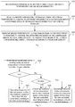
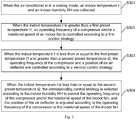
- Fig. 1 is a flowchart illustrating a method for controlling an air conditioner according to an exemplary embodiment. As shown in Fig. 1 , the method includes: S101, when the air conditioner is in a cooling mode, an indoor temperature t and an indoor humidity RH are collected.
- an operation mode of the air conditioner can be adjusted through a remote controller of the air conditioner, a control panel on an indoor unit of the air conditioner or a mobile terminal with a remote control function for the air conditioner, for example, the air conditioner can be controlled to perform a cooling mode by clicking a cooling mode button on the remote controller.
- the air conditioner is installed in an indoor space such as a living room, a bedroom and a conference room. Therefore, a current temperature and humidity of the indoor space such as the living room, the bedroom or the conference room where the air conditioner is installed can be obtained through S 101, the current temperature and humidity is the indoor temperature t and indoor humidity RH obtained in real time in this process of the present disclosure.
- the air conditioner is provided with a temperature sensor for detecting a current temperature of an indoor environment.
- a sensing end of the temperature sensor can be provided on an air inlet or an outer wall of a casing of the air conditioner, so that the current temperature detected by the first temperature sensor can be the same as or similar to an actual temperature of the indoor environment, thereby improving the accuracy of adjusting the operating frequency of the compressor and the rotational speed of the indoor fan of the air conditioner according to the current temperature of the indoor environment.
- the air conditioner is provided with a humidity sensor for detecting a current humidity of the indoor environment, the current humidity is the indoor humidity RH obtained in real time in this process of the present disclosure.
- a sensing end of the humidity sensor can be provided on the air inlet or the outer wall of the casing of the air conditioner, so that the current humidity detected by the humidity sensor can be the same as or similar to an actual humidity of the indoor environment, thereby improving the accuracy of adjusting the operating frequency of the compressor and the rotational speed of the indoor fan of the air conditioner according to the current humidity of the indoor environment.
- a corresponding control strategy is selected according to the indoor humidity RH to control the operating frequency of the compressor and/or the rotational speed of the indoor fan.
- An air-conditioning system is preset with a first preset temperature t1 as a judgment condition for controlling the operating frequency of the compressor and the rotational speed of the indoor fan.
- a first preset temperature t1 a judgment condition for controlling the operating frequency of the compressor and the rotational speed of the indoor fan.
- the indoor temperature t When the indoor temperature t is less than or equal to the first preset temperature t1, the indoor temperature t meets the cooling needs of the user, at this time, the indoor environmental humidity needs to be adjusted to improve the user comfort; the corresponding control strategy is selected according to the indoor humidity RH to unilaterally control the operating frequency of the compressor or the rotational speed of the indoor fan, or simultaneously adjust the operating frequency of the compressor or the rotational speed of the indoor fan to speed up the adjustment of the humidity.
- the indoor temperature and the indoor humidity are collected in real time; different control strategies are determined according to the relationship between the indoor temperature and the preset temperature and the indoor humidity, to take into account the adjustment of the indoor temperature and the indoor humidity; and thus the operating frequency of the compressor and the rotational speed of the indoor fan are adjusted, so that both the indoor temperature and the humidity can meet the requirements of user comfort, thereby avoiding the influence of fluctuations in other environmental parameters caused by adjusting a single indoor environmental parameter.
- the first preset temperature t1 is associated with a target temperature T, wherein the target temperature T is set by a user.
- the user can set target temperature T through a remote controller of the air conditioner, a control panel on an indoor unit of the air conditioner, or a mobile terminal with a remote control function for the air conditioner.
- K 24°C, 25°C, or 26°C.
- N 2.5°C, 3°C, or 3.5°C.
- M 1.5°C, 2°C, or 2.5°C.
- Fig. 2 is a flowchart illustrating a method for controlling an air conditioner according to an exemplary embodiment. As shown in Fig. 2 , the method includes: S201, when the air conditioner is in a cooling mode, an indoor temperature t and an indoor humidity RH are collected.
- the indoor temperature t is greater than the first preset temperature t1, the temperature deviation is larger, a cooling process is required, and thus the operating frequency of the compressor and/or the rotational speed of the indoor fan are controlled according to the first control strategy, so as to reduce the indoor temperature.
- the operating frequency of the compressor and/or the rotational speed of the indoor fan are controlled according to a third control strategy.
- the operating frequency of the compressor and/or the rotational speed of the indoor fan are controlled according to a fourth control strategy.
- the operating frequency of the compressor is kept unchanged.
- the rotational speed of the indoor fan is kept unchanged.
- the operating frequency of the compressor and the rotational speed of the indoor fan are kept unchanged.
- the operating frequency of the compressor and/or the rotational speed of the indoor fan are controlled by using a dual temperature difference PID method, so as to ensure comfortable indoor air outlet and improve indoor relative humidity at the same time.
- the controlling the operating frequency of the compressor and/or the rotational speed of the indoor fan according to the fourth control strategy includes: performing one or more corrections on the target temperature T to obtain a corrected target temperature Tx, wherein the target temperature T is set by a user; determining the operating frequency F of the compressor according to the corrected target temperature Tx, and adjusting the operating frequency F of the compressor accordingly; and determining the rotational speed R of the indoor fan according to the operating frequency F of the compressor, and adjusting the rotational speed R of the indoor fan accordingly.
- the method further includes: adjusting the position of the air deflector according to the operating frequency of the compressor or the rotation speed of the indoor fan.
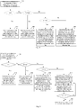
- Fig. 3 is a flowchart illustrating a method for controlling an air conditioner according to an exemplary embodiment. In this embodiment, only steps different from those of the foregoing embodiments will be described. As shown in Fig. 3 , the method includes:
- the air-conditioning system is preset with a first preset temperature t1 as a judgment condition for controlling the operating frequency of the compressor, the rotational speed of the indoor fan, and the position of the air deflector.
- a first preset temperature t1 as a judgment condition for controlling the operating frequency of the compressor, the rotational speed of the indoor fan, and the position of the air deflector.
- the indoor temperature t is less than or equal to the first preset temperature t1 and greater than the second preset temperature t2
- the indoor temperature t is close to a specified temperature, and the indoor temperature t meets the cooling needs of the user, at this time, the operating frequency of the compressor and the position of the air deflector are controlled according to the second control strategy, so as to reduce the energy consumption of the air conditioner and save energy.
- the corresponding control strategy is selected according to the collected indoor humidity RH to control the operating frequency of the compressor or the position of the air deflector, or simultaneously control the operating frequency of the compressor, the rotational speed of the indoor fan and the position of the air deflector to adjust the temperature and humidity of the indoor environment, so as to improve the user comfort.
- the indoor temperature and the indoor humidity are collected in real time; different control strategies are determined according to the relationship between the indoor temperature and the preset temperature and the indoor humidity, to take into account the adjustment of the indoor temperature and the indoor humidity; and thus one or more of the operating frequency of the compressor, the rotational speed of the indoor fan and the position of the air deflector are adjusted, so that both the indoor temperature and the humidity can meet the requirements of the user comfort, thereby avoiding the influence of fluctuations in other environmental parameters caused by adjusting a single indoor environmental parameter.
- the first preset temperature t1 and the second preset temperature t2 are associated with the target temperature T, wherein the target temperature T is set by the user.
- the user can set target temperature T through the remote controller of the air conditioner, the control panel on an indoor unit of the air conditioner, or the mobile terminal with the remote control function for the air conditioner.
- K 24°C, 25°C, or 26°C.
- N 2.5°C, 3°C, or 3.5°C.
- M 1.5°C, 2°C, or 2.5°C.
- Q 1°C, 2°C, or 3°C.
- Fig. 4 is a flowchart illustrating a method for controlling an air conditioner according to an exemplary embodiment. As shown in Fig. 4 , the method includes: S401, when the air conditioner is in a cooling mode, an indoor temperature t and an indoor humidity RH are collected.
- the indoor temperature t is greater than the first preset temperature t1
- the temperature deviation is larger
- a cooling process is required, and thus the operating frequency of the compressor and/or the rotational speed of the indoor fan are controlled according to a first control strategy, so as to reduce the indoor temperature.
- the operating frequency of the compressor and/or the rotational speed of the indoor fan and the position of the air deflector are controlled according to a third control strategy, and the position of the air deflector is adjusted according to the operating frequency of the compressor or the rotational speed of the indoor fan.
- the operating frequency of the compressor and/or the rotational speed of the indoor fan and the position of the air deflector are controlled according to a fourth control strategy to control the temperature and humidity, and the position of the air deflector is adjusted according to the operating frequency of the compressor or the rotational speed of the indoor fan.
- the controlling the operating frequency of the compressor and the position of the air deflector according to the second control strategy includes: adjusting the operating frequency F of the compressor to a specified frequency f1, and adjusting the air deflector to a maximum air outlet position.
- the operating frequency of the compressor and/or the rotational speed of the indoor fan are controlled by using a dual temperature difference PID method, so as to ensure comfortable indoor air outlet and improve indoor relative humidity at the same time.
- the controlling the operating frequency of the compressor and/or the rotational speed of the indoor fan according to the fourth control strategy includes: performing one or more corrections on the target temperature T to obtain a corrected target temperature Tx, wherein the target temperature T is set by a user; determining the operating frequency F of the compressor according to the corrected target temperature Tx, and adjusting the operating frequency F of the compressor accordingly; and determining the rotational speed R of the indoor fan according to the operating frequency F of the compressor, and adjusting the rotational speed R of the indoor fan accordingly.
- the first preset humidity Rh is 52%, and a gold humidity is 52% after being statistically calculated by means of big data. Under this humidity, human body comfort is the best, and at the same time, the growth of bacteria and mold in this environment can also be suppressed.
- Fig. 5 is a flowchart illustrating a method for controlling an air conditioner according to an exemplary embodiment.
- the indoor temperature t is less than or equal to the second preset temperature t2 and the indoor humidity RH is greater than or equal to the first preset humidity Rh
- the operating frequency of the compressor and/or the rotational speed of the indoor fan are controlled according to the fourth control strategy is performed; when the indoor temperature t is greater than a third preset temperature t3, that is, t3 ⁇ t ⁇ t2, if the rotational speed R of the indoor fan is less than or equal to the specified rotational speed R', the air deflector is adjusted to a minimum air outlet position; and if the rotational speed R of the indoor fan is greater than the specified rotational speed R', the air deflector is adjusted to the maximum air outlet position; and when the indoor temperature t is less than or equal to the third preset temperature t3, that is, t ⁇ t3, the indoor fan is adjusted to run at a maximum rotational speed, and the air deflector is adjusted to the minimum air outlet position, at this time, the indoor temperature t is less than or equal to the third preset temperature t
- the method before controlling the operating frequency of the compressor, the rotational speed of the indoor fan, or the position of the air deflector according to the indoor temperature t and the indoor humidity RH, the method further includes: receiving a mode switching instruction, and switching from a current operating mode to a first mode.
- the mode switching instruction is issued by a remote controller of the air conditioner, a control panel on an indoor unit of the air conditioner or a mobile terminal with a remote control function for the air conditioner.
- the first mode is a PMV mode.
- the PMV mode is an intelligent control mode for the human body comfort, after a PMV mode button on the remote controller of the air conditioner, the control panel on the indoor unit of the air conditioner or the mobile terminal with the remote control function for the air conditioner is pressed by the user, the air conditioner will switch to the PMV mode after receiving a PMV mode instruction, and collect parameters such as the indoor temperature, the indoor humidity, the rotational speed, a heat radiation, amounts of clothing, and amounts of activity.
- the controlling the operating frequency of the compressor and/or the rotational speed of the indoor fan by using the dual temperature difference PID method specifically includes the following steps: determining a temperature deviation between a temperature difference between a current temperature and a specified temperature and a first temperature difference determined last time; determining the operating frequency F of the compressor according to the temperature deviation, and adjusting the operating frequency F of the compressor accordingly; and determining the rotational speed R of the indoor fan according to the operating frequency F of the compressor, and adjusting the rotational speed R of the indoor fan accordingly.
- , Pt n
- the operating frequency F of the compressor is provided with an upper limit value and a lower limit value, so as to ensure the operation efficiency of the air conditioner and the service life of the compressor of the air conditioner.
- the operating frequency F of the compressor is set to the upper limit value; and when the calculated operating frequency F is less than a specified lower limit value, the operating frequency F of the compressor is set to the lower limit value.
- a range of the operating frequency F of the compressor is (36Hz, 65Hz), wherein the upper limit value and the lower limit value are determined by a large number of experiments and statistics carried out by different air-conditioning models and compressor models during commissioning stage.
- the calculated operating frequency F is greater than the upper limit value of 65 Hz, and thus, the operating frequency F of the compressor is set to the upper limit value of 65 Hz.
- the determining the rotational speed R of the indoor fan according to the operating frequency F of the compressor includes: the higher the operating frequency F of the compressor, the higher the rotational speed R of the indoor fan.
- An alternative method is to obtain the rotational speed of the indoor fan by searching from a table storing a preset corresponding relationship between the operating frequency F of the compressor and the rotational speed R of the indoor fan.
- the specific corresponding relationship is shown in Table 1: Table 1 Operating frequency of the compressor (Hz) Rotational speed of the indoor fan (r/min) 60 ⁇ 950 55 ⁇ 59 850 50 ⁇ 54 800 45 ⁇ 49 750 40 ⁇ 44 750 35 ⁇ 39 700
- the temperature of the coil is high, the ratio of the sensible heat is high, and the amount of the dehumidification is small; and when the indoor fan runs at a low speed, the temperature of the coil is low, the ratio of the latent heat is high, and the amount of the dehumidification is large.
- the rotational speeds of the indoor fans corresponding to different operating frequency ranges of the compressor are different, the rotational speed of the indoor fan corresponding to a low frequency range is low, and the rotational speed of the indoor fan corresponding to a high frequency range is high, although the lower a wind speed is at a certain frequency, the larger the amount of the dehumidification is, the excessively low wind speed in the high frequency range will cause the risk of freezing of the coil in the indoor unit.
- the adjusting the position of the air deflector according to the rotational speed R of the indoor fan includes: when the rotational speed R of the indoor fan is greater than a specified rotational speed R', adjusting the air deflector to the maximum air outlet position; and when the rotational speed R of the indoor fan is less than or equal to the specified rotational speed R', adjusting the air deflector to a minimum air outlet position.
- the adjusting the position of the air deflector according to the operating frequency F of the compressor includes: when the operating frequency F of the compressor is greater than a specified operating frequency F', adjusting the air deflector to the maximum air outlet position; and when the operating frequency F of the compressor is less than or equal to the specified operating frequency F', adjusting the air deflector to a minimum air outlet position.
- the air deflector When the operating frequency F of the compressor is greater than the specified operating frequency F', it is indicated that the operating frequency F is a high frequency, at this time, the air deflector is adjusted to the maximum air outlet position; and when the operating frequency F of the compressor is less than or equal to the specified operating frequency F', it is indicated that the operating frequency F is a low frequency, at this time, the air deflector is adjusted to the minimum air outlet position.
- F' is 50Hz
- the air deflector when the operating frequency F is 60Hz, the air deflector is adjusted to the maximum air outlet position; and when the operating frequency F is 40Hz, the air deflector is adjusted to the minimum air outlet position.
- Tx is a temperature after this correction
- Tx1 is a temperature after the previous correction
- Dset is a correction value.
- Dset is a fixed value, or, Dset is a variable.
- the external environment temperature includes an indoor environment temperature or an outdoor environment temperature.
- the selection of RH_KI and RH_Kp is related to a throttling device being a capillary or an expansion valve, a displacement performance of the compressor or a size of a condenser and an evaporator.
- the correction value Dset in order to prevent overshoot, is provided with an upper limit and a lower limit. If the calculated correction value Dset is greater than a specified upper limit value, the upper limit value is used as the correction value Dset; and if the calculated correction value Dset is less than a specified lower limit value, the lower limit value is used as the correction value Dset.
- the upper limit value is 0.2
- the lower limit value is -0.2; when the calculated correction value Dset is 0.3, the upper limit value 0.2 is taken as the correction value Dset, and when the calculated correction value Dset is -0.4, the lower limit value -0.2 is taken as the correction value Dset.
- the external environment temperature includes an indoor environment temperature or an outdoor environment temperature.
- the selection of T_Ki and T_Kp is related to a throttling device being a capillary or an expansion valve, a displacement performance of the compressor or a size of a condenser and an evaporator.
- T_Ki has a range of 1 to 10
- T_Kp has a range of 1 to 8.
- T_Ki 3, 4, 5, 6, or 7
- T_Kp 3, 4, 5, 6, or 7.
- the operating frequency F of the compressor is provided with an upper limit value and a lower limit value, so as to ensure the operation efficiency of the air conditioner and the service life of the compressor of the air conditioner.
- the operating frequency F of the compressor is set to the upper limit value; and when the calculated operating frequency F is less than a specified lower limit value, the operating frequency F of the compressor is set to the lower limit value.
- determining the rotational speed R of the indoor fan according to the operating frequency F of the compressor includes: the higher the operating frequency F of the compressor, the higher the rotational speed R of the indoor fan.
- the indoor temperature T set by the user is 29°C or 30°C, and the operating frequency of the compressor and/or the rotational speed of the indoor fan is controlled only according to the first control strategy, so as to control the indoor temperature.
- the rotational speed of the indoor fan is determined by a system according to the operating frequency of the compressor; and if the user changes the rotational speed of the indoor fan during the operation of the air conditioner, the air conditioner exits to control the operating frequency of the compressor and/or the rotational speed of the indoor fan and the position of the air deflector conditioner according to the fourth control strategy.
- the user changes the rotational speed of the indoor fan according to different needs, and the air conditioner exits to control the operating frequency of the compressor and/or the rotational speed of the indoor fan and the position of the air deflector conditioner according to the fourth control strategy, so as to meet the user needs.
- the current operating frequency of the compressor and the current rotational speed of the indoor fan are kept for a first specified time, and then the control strategy is switched.
- the first specified time has a range of 30S to 90S.
- the first specified time is 30S, 60S, or 90S.
- the following are device embodiments of the present disclosure, and the device embodiments may be configured to execute the method embodiments of the present disclosure.
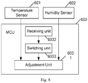
- Fig. 6 is a structural block diagram illustrating a device for controlling an air conditioner according to an exemplary embodiment. As shown in Fig. 6 , the device includes: a temperature sensor 601, a humidity sensor 602, and a microcontroller unit MCU 603, wherein the MCU 603 includes an adjustment unit 6031.
- the temperature sensor 601 is configured to collect an indoor temperature t.
- the humidity sensor 602 is configured to collect an indoor humidity RH
- a sensing end of the temperature sensor can be provided on an air inlet or an outer wall of a casing of the air conditioner, and a sensing end of the humidity sensor can be provided on the air inlet or the outer wall of the casing of the air conditioner.
- the adjustment unit 6031 is configured to, when the air conditioner is in a cooling mode, when the indoor temperature t is greater than a first preset temperature t1, control an operating frequency of a compressor and/or a rotational speed of an indoor fan according to a first control strategy; and when the indoor temperature t is less than or equal to the first preset temperature t1, select a corresponding control strategy according to the indoor humidity RH to control the operating frequency of the compressor and/or the rotational speed of the indoor fan; or, control the operating frequency of the compressor and a position of an air deflector according to a second control strategy.
- the indoor temperature and the indoor humidity are collected in real time; different control strategies are determined according to the relationship between the indoor temperature and the preset temperature and the indoor humidity, to take into account the adjustment of the indoor temperature and the indoor humidity; and thus one or more of the operating frequency of the compressor, the rotational speed of the indoor fan and the position of the air deflector are adjusted, so that both the indoor temperature and the humidity can meet the requirements of user comfort, thereby avoiding the influence of fluctuations in other environmental parameters caused by adjusting a single indoor environmental parameter.
- the first preset temperature t' is associated with a target temperature T, wherein the target temperature T is set by a user.
- the user can set target temperature T through a remote controller of the air conditioner, a control panel on an indoor unit of the air conditioner, or a mobile terminal with a remote control function for the air conditioner.
- the adjustment unit 6031 is configured to, when the air conditioner is in the cooling mode, when the indoor temperature t is greater than the first preset temperature t1, control the operating frequency of the compressor and/or the rotational speed of the indoor fan according to the first control strategy; and when the indoor temperature t is less than or equal to the first preset temperature t1, select the corresponding control strategy according to the indoor humidity to control the operating frequency of the compressor and/or the rotational speed of the indoor fan.
- the indoor temperature and the indoor humidity are collected in real time; different control strategies are determined according to the relationship between the indoor temperature and the preset temperature and the indoor humidity, to take into account the adjustment of the indoor temperature and the indoor humidity; and thus the operating frequency of the compressor and the rotational speed of the indoor fan are adjusted, so that both the indoor temperature and the humidity can meet the requirements of user comfort, thereby avoiding the influence of fluctuations in other environmental parameters caused by adjusting a single indoor environmental parameter.
- the first preset temperature t1 is associated with the target temperature T, wherein the target temperature T is set by the user.
- the user can set target temperature T through the remote controller of the air conditioner, the control panel on the indoor unit of the air conditioner, or the mobile terminal with the remote control function for the air conditioner.
- the first preset temperature t' K+N
- the indoor temperature T set by the user is less than or equal to K
- the first preset temperature t' K+M, where K, N, and M are preset temperatures, and N is greater than or equal to M.
- K 24°C, 25°C, or 26°C.
- N 2.5°C, 3°C, or 3.5°C.
- M 1.5°C, 2°C, or 2.5°C.
- the adjustment unit 6031 is configured to, when the indoor temperature t is less than or equal to the first preset temperature t1, if the indoor humidity RH is less than a first preset humidity Rh, that is, RH ⁇ Rh, control the operating frequency of the compressor and/or the rotational speed of the indoor fan according to a third control strategy; and if the indoor humidity RH is greater than or equal to the first preset humidity Rh, that is, RH ⁇ Rh, control the operating frequency of the compressor and/or the rotational speed of the indoor fan according to a fourth control strategy.
- the adjustment unit 6031 is configured to, when the indoor temperature t is less than or equal to the first preset temperature t1 and the indoor humidity RH is less than a first preset humidity Rh, keep the operating frequency of the compressor unchanged.
- the adjustment unit 6031 is configured to, when the indoor temperature t is less than or equal to the first preset temperature t1 and the indoor humidity RH is less than a first preset humidity Rh, keep the rotational speed of the indoor fan unchanged.
- the adjustment unit 6031 is configured to, when the indoor temperature t is less than or equal to the first preset temperature t1 and the indoor humidity RH is less than a first preset humidity Rh, keep the operating frequency of the compressor and the rotational speed of the indoor fan unchanged.
- the adjustment unit 6031 is configured to, when the indoor temperature t is less than or equal to the first preset temperature t1 and the indoor humidity RH is less than the first preset humidity Rh, control the operating frequency of the compressor and/or the rotational speed of the indoor fan by using the dual temperature difference PID method, so as to ensure comfortable indoor air outlet and improve indoor relative humidity at the same time.
- the MCU further includes: a determination unit (not shown in Fig. 6 ) configured to determine a temperature deviation between a temperature difference between a current temperature and a specified temperature and a first temperature difference determined last time, determine the operating frequency F of the compressor according to the temperature deviation, and determine the rotational speed R of the indoor fan according to the operating frequency F of the compressor.
- the adjustment unit 6031 is further configured to adjust the position of the air deflector according to the operating frequency of the compressor or the rotational speed of the indoor fan.
- the adjustment unit 6031 is configured to adjust the operating frequency of the compressor accordingly according to the operating frequency F of the compressor determined by the determination unit; adjust the rotational speed of the indoor fan accordingly according to the rotational speed R of the indoor fan determined by the determination unit; and adjust the air deflector according to the position of the air deflector determined by the determination unit.
- the determination unit is configured to calculate the operating frequency F of the compressor according to the formula (1).
- the rotational speed R of the indoor fan is determined according to the operating frequency F of the compressor, wherein the higher the operating frequency F of the compressor, the higher the rotational speed R of the indoor fan.
- the rotational speed R of the indoor fan is determined according to Table 1. In other embodiments, the rotational speed R of the indoor fan is calculated according to the formula (2).
- the adjustment unit 6031 is configured to, when the indoor temperature t is greater than a first preset temperature t1, control an operating frequency of a compressor and/or a rotational speed of an indoor fan according to a first control strategy; when the indoor temperature t is less than or equal to the first preset temperature t1 and greater than a second preset temperature t2, control the operating frequency of the compressor and a position of an air deflector according to a second control strategy; and when the indoor temperature t is less than or equal to the second preset temperature t2, select the corresponding control strategy according to the indoor humidity RH to control the operating frequency of the compressor and/or the rotational speed of the indoor fan, and adjust the position of the air deflector according to the operating frequency of the compressor or the rotational speed of the indoor fan.
- the indoor temperature and the indoor humidity are collected in real time; different control strategies are determined according to the relationship between the indoor temperature and the preset temperature and the indoor humidity, to take into account the adjustment of the indoor temperature and the indoor humidity; and thus the operating frequency of the compressor, the rotational speed of the indoor fan and the position of the air deflector are adjusted, so that both the indoor temperature and the humidity can meet the requirements of user comfort, thereby avoiding the influence of fluctuations in other environmental parameters caused by adjusting a single indoor environmental parameter.
- the first preset temperature t1 and the second preset temperature t2 are associated with a target temperature T, wherein the target temperature T is set by a user.
- the user can set target temperature T through a remote controller of the air conditioner, a control panel on an indoor unit of the air conditioner, or a mobile terminal with a remote control function for the air conditioner.
- K 24°C, 25°C, or 26°C.
- N 2.5°C, 3°C, or 3.5°C.
- M 1.5°C, 2°C, or 2.5°C.
- Q 1°C, 2°C, or 3°C.
- the adjustment unit 6031 is further configured to, when the indoor temperature t is less than or equal to the second preset temperature t2, if the indoor humidity RH is less than a first preset humidity Rh, control the operating frequency of the compressor and/or the rotational speed of the indoor fan according to a third control strategy; and if the indoor humidity RH is greater than or equal to the first preset humidity Rh, control the operating frequency of the compressor and/or the rotational speed of the indoor fan according to a fourth control strategy.
- the first preset humidity Rh is 52%.
- the adjustment unit 6031 is configured to, when the indoor temperature t is less than or equal to the first preset temperature t1 and greater than the second preset temperature t2, adjust the operating frequency F of the compressor to a specified frequency f1, and adjust the air deflector to a maximum air outlet position.
- the specified frequency f1 can be a fixed value, which can be set according to the results of many tests, so as to ensure the energy saving effect of the air conditioner.
- the specified frequency f1 is 70% of the highest frequency of the compressor.
- the adjustment unit 6031 is further configured to, when the indoor humidity RH is less than the first preset humidity Rh, keep the operating frequency of the compressor and/or the rotational speed of the indoor fan unchanged; or, control the operating frequency of the compressor and/or the rotational speed of the indoor fan by using the dual temperature difference PID method.
- the adjustment unit 6031 is configured to, when the indoor temperature t is less than or equal to the first preset temperature t1 and the indoor humidity RH is less than a first preset humidity Rh, keep the operating frequency of the compressor unchanged.
- the adjustment unit 6031 is configured to, when the indoor temperature t is less than or equal to the first preset temperature t1 and the indoor humidity RH is less than a first preset humidity Rh, keep the rotational speed of the indoor fan unchanged.
- the adjustment unit 6031 is configured to, when the indoor temperature t is less than or equal to the first preset temperature t1 and the indoor humidity RH is less than a first preset humidity Rh, keep the operating frequency of the compressor and the rotational speed of the indoor fan unchanged.
- the adjustment unit 6031 is configured to, when the indoor temperature t is less than or equal to the first preset temperature t1 and the indoor humidity RH is less than the first preset humidity Rh, control the operating frequency of the compressor and/or the rotational speed of the indoor fan by using the dual temperature difference PID method, so as to ensure comfortable indoor air outlet and improve indoor relative humidity at the same time.
- the MCU further includes: a determination unit (not shown in Fig. 6 ) configured to determine a temperature deviation between a temperature difference between a current temperature and a specified temperature and a first temperature difference determined last time, determine the operating frequency F of the compressor according to the temperature deviation, and determine the rotational speed R of the indoor fan according to the operating frequency F of the compressor.
- the adjustment unit 6031 is configured to adjust the operating frequency of the compressor accordingly according to the operating frequency F of the compressor determined by the determination unit; and adjust the rotational speed of the indoor fan accordingly according to the rotational speed R of the indoor fan determined by the determination unit.
- determination unit is further configured to determine the position of the air deflector according to the rotational speed R of the indoor fan.
- the adjustment unit 6031 is configured to adjust the operating frequency of the compressor accordingly according to the operating frequency F of the compressor determined by the determination unit; adjust the rotational speed of the indoor fan accordingly according to the rotational speed R of the indoor fan determined by the determination unit; and adjust the air deflector according to the position of the air deflector determined by the determination unit.
- the determination unit is configured to calculate the operating frequency F of the compressor according to the formula (1).
- the rotational speed R of the indoor fan is determined according to the operating frequency F of the compressor, wherein the higher the operating frequency F of the compressor, the higher the rotational speed R of the indoor fan.
- the rotational speed R of the indoor fan is determined according to Table 1. In other embodiments, the rotational speed R of the indoor fan is calculated according to the formula (2).
- the device for controlling an air conditioner further includes a calculation unit 6034.
- the calculation unit 6034 is configured to, when the indoor temperature t is less than or equal to the first preset temperature t' and when the indoor humidity RH is greater than or equal to the first preset humidity Rh, calculate a correction value of the target temperature T to obtain a corrected temperature Tx, determine the operating frequency F of the compressor according to the corrected target temperature Tx, and determine the rotational speed R of the indoor fan according to the operating frequency F of the compressor, wherein the target temperature T is set by the user.
- the adjustment unit 6031 is further configured to adjust the operating frequency of the compressor accordingly according to the operating frequency F of the compressor determined by the calculation unit 6034; and adjust the rotational speed of the indoor fan accordingly according to the rotational speed R of the indoor fan determined by the calculation unit 6034.
- Tx is a temperature after this correction
- Tx1 is a temperature after the previous correction
- Dset is a correction value.
- Dset is a fixed value, or, Dset is a variable.
- the calculation unit 6034 is configured to, when the correction is performed each time, calculate the correction value Dset according to a humidity difference Prh between the indoor humidity RH and a target humidity RHm and a change Drh of the indoor humidity. Specifically, Dset is calculated according to the formula (3).
- the calculation unit 6034 is configured to calculate the operating frequency F of the compressor according to a temperature difference PT between the indoor temperature t and the corrected target temperature Tx and a change DT of the indoor temperature. Specifically, F is calculated according to the formula (4).
- the calculation unit 6034 is configured to determine the rotational speed R of the indoor fan according to the operating frequency F of the compressor, wherein the higher the operating frequency F of the compressor, the higher the rotational speed R of the indoor fan.
- the rotational speed R of the indoor fan is determined according to Table 1. In other embodiments, the rotational speed R of the indoor fan is calculated according to the formula (2).
- the adjustment unit 6031 controls the operating frequency of the compressor and/or the rotational speed of the indoor fan according to the fourth control strategy; when the indoor temperature t is greater than a third preset temperature t3, that is, t3 ⁇ t ⁇ t2, if the rotational speed R of the indoor fan is less than or equal to the specified rotational speed R', the adjustment unit 6031 adjusts the air deflector to a minimum air outlet position; and if the rotational speed R of the indoor fan is greater than the specified rotational speed R', the adjustment unit 6031 adjusts the air deflector to the maximum air outlet position; and when the indoor temperature t is less than or equal to the third preset temperature t3, that is, t ⁇ t3, the adjustment unit 6031 adjusts the indoor fan to run at a maximum rotational speed, and adjusts the air deflector to the minimum air outlet position, at
- the device for controlling an air conditioner further includes: a receiving unit 6032 and a switching unit 6033.
- the receiving unit 6032 is configured to receive a mode switching instruction.
- the switching unit 6033 is configured to switch from a current operating mode to a first mode according to the mode switching instruction received by the receiving unit 6032.
- the first mode is a PMV mode.
- the rotational speed of the indoor fan is determined by a system according to the operating frequency of the compressor; and if the user changes the rotational speed of the indoor fan during the operation of the air conditioner, the air conditioner exits to control the operating frequency of the compressor and/or the rotational speed of the indoor fan and the position of the air deflector conditioner according to the fourth control strategy.
- the user changes the rotational speed of the indoor fan according to different needs, and the air conditioner exits to control the operating frequency of the compressor and/or the rotational speed of the indoor fan and the position of the air deflector conditioner according to the fourth control strategy, so as to meet the user needs.
- the current operating frequency of the compressor and the current rotational speed of the indoor fan are kept for a first specified time, and then the control strategy is switched.
- the first specified time has a range of 30S to 90S.
- the first specified time is 30S, 60S, or 90S.
- the present disclosure also includes an air conditioner including a compressor and an indoor fan, and further including the device described in any of the foregoing embodiments.
Landscapes
- Engineering & Computer Science (AREA)
- Physics & Mathematics (AREA)
- Chemical & Material Sciences (AREA)
- Combustion & Propulsion (AREA)
- Mechanical Engineering (AREA)
- General Engineering & Computer Science (AREA)
- Fluid Mechanics (AREA)
- Thermal Sciences (AREA)
- Air Conditioning Control Device (AREA)
Abstract
Description
- The application is based upon and claims priority to Chinese Patent Application No.
201710787980.8, filed September 4, 2017 - The application is based upon and claims priority to Chinese Patent Application No.
201710787083.7, filed September 4, 2017 - The present disclosure relates to the field of air conditioner technologies, and more particularly, to a method and a device for controlling self-cleaning of an air conditioner, and an air conditioner.
- At present, when an existing household air conditioner operates in a cooling mode, a large amount of condensed water is generated, and under appropriate humidity and temperature conditions, a large number of bacteria will breed, and the bacteria will be transported to a room with the supply air, which will seriously affect user comfort and health. According to related research, the bacteria are most likely to breed under high humidity or high temperature conditions.
- In addition, during an actual operation of the household air conditioner, when a deviation between a specified temperature and a room temperature is large, a compressor runs at high frequency, at this time, a temperature of a coil of an indoor unit is generally lower (lower than a dew point temperature of an air), and a water vapor in the air is continuously condensed, when the room temperature reaches the specified temperature, the humidity may already be very low, while the general air conditioner does not have a humidification function, at this time, the user will feel dry and uncomfortable; and when a difference between the room temperature and the specified temperature is very small, the air conditioner mostly operates at low frequency, at this time, the temperature of the coil of the indoor unit is generally higher (higher than the dew point temperature of the air), and the water vapor in the air will not be condensed, when the room temperature reaches the specified temperature, the humidity of the air may be too high, and the user will also feel uncomfortable. Therefore, existing methods for controlling the air conditioner often cannot take into account the adjustment of the indoor temperature and humidity, resulting in that the indoor temperature and humidity cannot meet comfort and health requirements of the user.
- Embodiments of the present disclosure provide a method and a device for controlling self-cleaning of an air conditioner, and an air conditioner, which aim to solve the problem that existing air conditioners cannot balance an indoor temperature and humidity adjustment. In order to basically understand some aspects of the disclosed embodiments, a brief summary is given below. The summary is not a general comment, nor tends to determine key/critical constituent elements or describe a protection scope of these embodiments, and only aims to present some concepts in a simplified form as an introduction of the following detailed description.
- According to a first aspect of the embodiments of the present disclosure, there is provided a method for controlling an air conditioner, including: when the air conditioner is in a cooling mode, collecting an indoor temperature t and an indoor humidity RH; when the indoor temperature t is greater than a first preset temperature t1, controlling an operating frequency of a compressor and/or a rotational speed of an indoor fan according to a first control strategy; and when the indoor temperature t is less than or equal to the first preset temperature t1, selecting a corresponding control strategy according to the indoor humidity RH to control the operating frequency of the compressor and/or the rotational speed of the indoor fan; or, controlling the operating frequency of the compressor and a position of an air deflector according to a second control strategy.
- Optionally, when the indoor temperature t is less than or equal to the first preset temperature t1 and greater than a second preset temperature t2, controlling the operating frequency of the compressor and the position of the air deflector according to the second control strategy, wherein the first preset temperature t1 is greater than the second preset temperature t2.
- Optionally, when the indoor temperature t is less than or equal to a second preset temperature t2, selecting the corresponding control strategy according to the indoor humidity RH to control the operating frequency of the compressor and/or the rotational speed of the indoor fan, wherein the first preset temperature t1 is greater than the second preset temperature t2.
- Optionally, after selecting the corresponding control strategy according to the indoor humidity RH to control the operating frequency of the compressor and/or the rotational speed of the indoor fan, further including: adjusting the position of the air deflector according to the operating frequency of the compressor or the rotational speed of the indoor fan.
- Optionally, the second preset temperature t2 is associated with a target temperature T, wherein the target temperature T is set by a user.
- Optionally, the first preset temperature t1 is associated with a target temperature T, wherein the target temperature T is set by a user.
- Optionally, when the indoor temperature T set by the user is greater than K, the first preset temperature t1=K+N; and when the indoor temperature T set by the user is less than or equal to K, the first preset temperature t1=K+M, where K, N, M, and Q are preset temperatures, N is greater than or equal to M, and N and M are greater than Q.
- Preferably, K=24°C, 25°C, or 26°C. Preferably, N= 2.5°C, 3°C, or 3.5°C. Preferably, M=1.5°C, 2°C, or 2.5°C. Preferably, Q=1°C, 2°C, or 3°C.
- Optionally, when the indoor temperature T set by the user is greater than K, the first preset temperature t1=K+N, and the second preset temperature t2=K+N-Q; and when the indoor temperature T set by the user is less than or equal to K, the first preset temperature t1=K+M, and the second preset temperature t2=K+M-Q, where K, N, M, and Q are preset temperatures, the first preset temperature t1 is greater than the second preset temperature t2, N is greater than or equal to M, and N and M are greater than Q.
- Preferably, K=24°C, 25°C, or 26°C. Preferably, N= 2.5°C, 3°C, or 3.5°C. Preferably, M=1.5°C, 2°C, or 2.5°C. Preferably, Q=1°C, 2°C, or 3°C.
- Optionally, the controlling the operating frequency of the compressor and the position of the air deflector according to the second control strategy includes: adjusting the operating frequency F of the compressor to a specified frequency f1, and adjusting the air deflector to a maximum air outlet position.
- Optionally, the selecting the corresponding control strategy according to the indoor humidity RH to control the operating frequency of the compressor and/or the rotational speed of the indoor fan includes: when the indoor humidity RH is less than a first preset humidity Rh, controlling the operating frequency of the compressor and/or the rotational speed of the indoor fan according to a third control strategy; and when the indoor humidity RH is greater than or equal to the first preset humidity Rh, controlling the operating frequency of the compressor and/or the rotational speed of the indoor fan according to a fourth control strategy.
- Optionally, the first preset humidity Rh is 52%.
- Optionally, the controlling the operating frequency of the compressor and/or the rotational speed of the indoor fan according to the third control strategy includes: keeping the operating frequency of the compressor and/or the rotational speed of the indoor fan unchanged; or, controlling the operating frequency of the compressor and/or the rotational speed of the indoor fan by using a dual temperature difference PID method.
- Optionally, the controlling the operating frequency of the compressor and/or the rotational speed of the indoor fan by using the dual temperature difference PID method includes: determining a temperature deviation between a temperature difference between a current temperature and a specified temperature and a first temperature difference determined last time; determining the operating frequency F of the compressor according to the temperature deviation, and adjusting the operating frequency F of the compressor accordingly; and determining the rotational speed R of the indoor fan according to the operating frequency F of the compressor, and adjusting the rotational speed R of the indoor fan accordingly.
- Optionally, the determining the operating frequency F of the compressor according to the temperature deviation includes: calculating the operating frequency F of the compressor according to the following formula:

where Dtn=|Ptn-Ptn-1|, Ptn=|Tn-Tm|, t1_Ki is a temperature deviation coefficient, t1_Kp is a temperature difference coefficient, C is an operating frequency coefficient, Dtn is the temperature deviation, Ptn is the temperature difference, Tn is the current temperature, and Tm is the specified temperature. - Optionally, when the calculated operating frequency F is greater than a specified upper limit value, setting the operating frequency F of the compressor to the upper limit value; and when the calculated operating frequency F is less than a specified lower limit value, setting the operating frequency F of the compressor to the lower limit value.
- Optionally, the determining the rotational speed R of the indoor fan according to the operating frequency F of the compressor includes: the higher the operating frequency F of the compressor, the higher the rotational speed R of the indoor fan.
- Optionally, the adjusting the position of the air deflector according to the operating frequency of the compressor or the rotational speed of the indoor fan includes: adjusting the position of the air deflector according to the rotational speed of the indoor fan; when the rotational speed R of the indoor fan is greater than a specified rotational speed R', adjusting the air deflector to the maximum air outlet position; and when the rotational speed R of the indoor fan is less than or equal to the specified rotational speed R', adjusting the air deflector to a minimum air outlet position.
- Optionally, the controlling the operating frequency of the compressor and/or the rotational speed of the indoor fan according to the fourth control strategy includes: performing one or more corrections on the target temperature T to obtain a corrected temperature Tx, wherein the target temperature T is set by a user; determining the operating frequency F of the compressor according to the corrected target temperature Tx, and adjusting the operating frequency F of the compressor accordingly; and determining the rotational speed R of the indoor fan according to the operating frequency F of the compressor, and adjusting the rotational speed R of the indoor fan accordingly.
- Optionally, the performing one or more corrections on the target temperature T includes: when the correction is performed for the first time, Tx=T-Dset; and when the correction is performed for the second and subsequent times, Tx=Txl-Dset, where Tx is a temperature after this correction, Tx1 is a temperature after the previous correction, and Dset is a correction value. Optionally, Dset is a fixed value, or, Dset is a variable.
- Optionally, when the correction is performed each time, calculating the correction value Dset according to a humidity difference Prh between the indoor humidity RH and a target humidity RHm and a change Drh of the indoor humidity, where Dset=Int{[RH_Ki×Prh+RH_Kp×Drh]×100}/100, Prh=RH-RHm, Drh=RH-RH1, RH1 is an indoor humidity collected last time, and RH_Kp and RH_Ki are specified weighting coefficients respectively; wherein, a selection of RH Kp is related to a system configuration and an external environment temperature, and a selection of RH_Ki is related to the system configuration and the external environment temperature. If the calculated correction value Dset is greater than the specified upper limit value, the upper limit value is used as the correction value Dset; and if the calculated correction value Dset is less than the specified lower limit value, the lower limit value is used as the correction value Dset.
- Optionally, the method further includes: receiving a mode switching instruction, and switching from a current operating mode to a first mode.
- Optionally, the first mode is a PMV mode for predicting the average number of votes.
- Optionally, when the indoor temperature T set by the user is a specified value, controlling the operating frequency of the compressor and/or the rotational speed of the indoor fan only according to the first control strategy, so as to control the indoor temperature.
- Optionally, the specified value is 29°C or 30°C.
- Optionally, when the operating frequency of the compressor and/or the rotational speed of the indoor fan are controlled according to the fourth control strategy, determining, by a system, the rotational speed of the indoor fan according to the operating frequency of the compressor; and if the user changes the rotational speed of the indoor fan during the operation of the air conditioner, exiting, by the air conditioner, to control the operating frequency of the compressor and/or the rotational speed of the indoor fan according to the fourth control strategy.
- Optionally, when it is detected that the indoor temperature t or the indoor humidity changes and the control strategy needs to be adjusted, keeping the current operating frequency of the compressor and the current rotational speed of the indoor fan for a first specified time, and then switching the control strategy.
- Optionally, the first specified time has a range of 30S to 90S. Preferably, the first specified time is 30S, 60S, or 90S.
- According to a second aspect of the embodiments of the present disclosure, there is provided a device for controlling an air conditioner, including a temperature sensor for collecting an indoor temperature t, a humidity sensor for collecting an indoor humidity RH, and a microcontroller unit MCU, wherein the MCU includes: an adjustment unit configured to, when the air conditioner is in a cooling mode, when the indoor temperature t is greater than a first preset temperature t', control an operating frequency of a compressor and/or a rotational speed of an indoor fan according to a first control strategy; and when the indoor temperature t is less than or equal to the first preset temperature t', select a corresponding control strategy according to the indoor humidity RH to control the operating frequency of the compressor and/or the rotational speed of the indoor fan.
- Optionally, the first preset temperature t1 is associated with a target temperature T, wherein the target temperature T is set by a user.
- Optionally, when selecting the corresponding control strategy according to the indoor humidity to control the operating frequency of the compressor and/or the rotational speed of the indoor fan, the adjustment unit is specifically configured to control the operating frequency of the compressor and/or the rotational speed of the indoor fan according to a third control strategy when the indoor humidity RH is less than a first preset humidity Rh, and control the operating frequency of the compressor and/or the rotational speed of the indoor fan according to a fourth control strategy when the indoor humidity RH is greater than or equal to the first preset humidity Rh.
- Optionally, when controlling the operating frequency of the compressor and/or the rotating speed of the indoor fan according to the third control strategy, the adjustment unit is specifically configured to keep the operating frequency of the compressor and/or the rotational speed of the indoor fan unchanged, or, control the operating frequency of the compressor and/or the rotational speed of the indoor fan by using a dual temperature difference PID method.
- Optionally, when controlling the operating frequency of the compressor and/or the rotating speed of the indoor fan according to the third control strategy, the adjustment unit is specifically configured to keep the operating frequency of the compressor and/or the rotational speed of the indoor fan unchanged; or, control the operating frequency of the compressor and/or the rotational speed of the indoor fan by using a dual temperature difference PID method.
- Preferably, the first preset humidity Rh is 52%.
- Optionally, the MCU further includes: a determination unit configured to determine a temperature deviation between a temperature difference between a current temperature and a specified temperature and a first temperature difference determined last time, determine the operating frequency F of the compressor according to the temperature deviation and adjust the operating frequency F of the compressor accordingly, and determine the rotational speed R of the indoor fan according to the operating frequency F of the compressor and adjust the rotational speed R of the indoor fan accordingly; and when controlling the operating frequency of the compressor and/or the rotational speed of the indoor fan by using a dual temperature difference PID method, the adjustment unit is specifically configured to adjust the operating frequency F of the compressor accordingly according to the operating frequency F of the compressor determined by the determination unit, and adjust the rotational speed R of the indoor fan accordingly according to the rotational speed of the indoor fan determined by the determination unit.
- Optionally, the determination unit is configured to calculate the operating frequency F of the compressor according to the following formula:

where Dtn=|Ptn-Ptn-1|, Ptn=|Tn-Tm|, T'_Ki is a temperature deviation coefficient, T'_Kp is a temperature difference coefficient, C is an operating frequency coefficient, Dtn is the temperature deviation, Ptn is the temperature difference, Tn is the current temperature, and Tm is the specified temperature. - Optionally, when the calculated operating frequency F is greater than a specified upper limit value, the operating frequency F of the compressor is set to the upper limit value; and when the calculated operating frequency F is less than a specified lower limit value, the operating frequency F of the compressor is set to the lower limit value.
- Optionally, the determining the rotational speed R of the indoor fan according to the operating frequency F of the compressor includes: the higher the operating frequency F of the compressor, the higher the rotational speed R of the indoor fan.
- Optionally, when adjusting the position of the air deflector according to the operating frequency of the compressor or the rotational speed of the indoor fan, the adjustment unit is specifically configured to adjust the air deflector to the maximum air outlet position when the rotational speed R of the indoor fan is greater than a specified rotational speed R', and adjust the air deflector to a minimum air outlet position when the rotational speed R of the indoor fan is less than or equal to the specified rotational speed R'.
- Optionally, the MCU further includes: a calculation unit configured to, when the indoor temperature t is less than or equal to the first preset temperature t1 and when the indoor humidity RH is greater than or equal to the first preset humidity Rh, calculate a correction value of the target temperature T to obtain a corrected temperature Tx, determine the operating frequency F of the compressor according to the corrected target temperature Tx, and determine the rotational speed R of the indoor fan according to the operating frequency F of the compressor, wherein the target temperature T is set by a user; and the adjustment unit is further configured to adjust the operating frequency of the compressor accordingly according to the operating frequency F of the compressor determined by the calculation unit, and adjust the rotational speed of the indoor fan accordingly the rotational speed R of the indoor fan determined by the calculation unit.
- Optionally, the calculation unit is configured to obtain the corrected temperature Tx according to Tx=T-Dset when the correction is performed for the first time, and obtain the corrected temperature Tx according to Tx=Txl-Dset when the correction is performed for the second and subsequent times, where Tx is a temperature after this correction, Tx1 is a temperature after the previous correction, and Dset is a correction value. Optionally, Dset is a fixed value, or, Dset is a variable.
- Optionally, when the correction is performed each time, calculating the correction value Dset according to a humidity difference Prh between the indoor humidity RH and a target humidity RHm and a change Drh of the indoor humidity, where Dset=Int{[RH _Ki×Prh+RH_Kp×Drh]×100}/100, Prh=RH-RHm, Drh=RH-RH1, RH1 is an indoor humidity collected last time, and RH_Kp and RH_Ki are specified weighting coefficients respectively; wherein, a selection of RH Kp is related to a system configuration and an external environment temperature, and a selection of RH_Ki is related to the system configuration and the external environment temperature. If the calculated correction value Dset is greater than the specified upper limit value, the upper limit value is used as the correction value Dset; and if the calculated correction value Dset is less than the specified lower limit value, the lower limit value is used as the correction value Dset.
- Optionally, the calculation unit is configured to calculate the operating frequency F of the compressor according to a temperature difference PT between the indoor temperature t and the corrected target temperature Tx and a change DT of the indoor temperature.
- Optionally, F=T_Kp×PT+T_Ki×DT; where PT=t-Tx, DT=t-t', t' is an indoor temperature collected last time, and T_Kp and T_Ki are weighting coefficients respectively. A selection of T_Kp is related to a system configuration and an external environment temperature, and a selection of T_Ki is related to the system configuration and the external environment temperature. T_Kp has a range of 1 to 8, and T_Ki has a range of 1 to 10. Preferably, T_Kp =3, 4, 5, 6, or 7, and T_Ki =3, 4, 5, 6, or 7.
- Optionally, when the calculated operating frequency F is greater than a specified upper limit value, the operating frequency F of the compressor is set to the upper limit value; and when the calculated operating frequency F is less than a specified lower limit value, the operating frequency F of the compressor is set to the lower limit value.
- Optionally, the determining the rotational speed R of the indoor fan according to the operating frequency F of the compressor includes: the higher the operating frequency F of the compressor, the higher the rotational speed R of the indoor fan.
- According to a third aspect of the embodiments of the present disclosure, there is provided a device for controlling an air conditioner, including a temperature sensor for collecting an indoor temperature t, a humidity sensor for collecting an indoor humidity RH, and a microcontroller unit MCU, wherein the MCU includes: an adjustment unit configured to, when the air conditioner is in a cooling mode, when the indoor temperature t is greater than a first preset temperature t1, control an operating frequency of a compressor and/or a rotational speed of an indoor fan according to a first control strategy; when the indoor temperature t is less than or equal to the first preset temperature t1 and greater than a second preset temperature t2, control the operating frequency of the compressor and a position of an air deflector according to a second control strategy; and when the indoor temperature t is less than or equal to the second preset temperature t2, select the corresponding control strategy according to the indoor humidity RH to control the operating frequency of the compressor and/or the rotational speed of the indoor fan, and adjust the position of the air deflector according to the operating frequency of the compressor or the rotational speed of the indoor fan.
- Optionally, the first preset temperature t1 and the second preset temperature t2 are associated with a target temperature T, wherein the target temperature T is set by a user.
- Optionally, when selecting the corresponding control strategy according to the indoor humidity RH to control the operating frequency of the compressor and/or the rotational speed of the indoor fan, the adjustment unit is specifically configured to, when the indoor temperature t is less than or equal to the second preset temperature t2 and the indoor humidity RH is less than a first preset humidity Rh, control the operating frequency of the compressor and/or the rotational speed of the indoor fan according to a third control strategy; and when the indoor temperature t is less than or equal to the second preset temperature t2 and the indoor humidity RH is greater than or equal to the first preset humidity Rh, control the operating frequency of the compressor and/or the rotational speed of the indoor fan according to a fourth control strategy.
- Optionally, the first preset humidity Rh is 52%.
- Optionally, when controlling the operating frequency of the compressor and/or the rotating speed of the indoor fan according to the third control strategy, the adjustment unit is specifically configured to keep the operating frequency of the compressor and/or the rotational speed of the indoor fan unchanged, or, control the operating frequency of the compressor and/or the rotational speed of the indoor fan by using a dual temperature difference PID method.
- Optionally, the MCU further includes: a determination unit configured to determine a temperature deviation between a temperature difference between a current temperature and a specified temperature and a first temperature difference determined last time, determine the operating frequency F of the compressor according to the temperature deviation and adjust the operating frequency F of the compressor accordingly, and determine the rotational speed R of the indoor fan according to the operating frequency F of the compressor and adjust the rotational speed R of the indoor fan accordingly; and when controlling the operating frequency of the compressor and/or the rotational speed of the indoor fan by using a dual temperature difference PID method, the adjustment unit is specifically configured to adjust the operating frequency F of the compressor accordingly according to the operating frequency F of the compressor determined by the determination unit, and adjust the rotational speed R of the indoor fan accordingly according to the rotational speed of the indoor fan determined by the determination unit.
- Optionally, the determination unit is configured to calculate the operating frequency F of the compressor according to the following formula:

where Dtn=|Ptn-Ptn-1|, Ptn=|Tn-Tm|, T'_Ki is a temperature deviation coefficient, T'_Kp is a temperature difference coefficient, C is an operating frequency coefficient, Dtn is the temperature deviation, Ptn is the temperature difference, Tn is the current temperature, and Tm is the specified temperature. - Optionally, when the calculated operating frequency F is greater than a specified upper limit value, the operating frequency F of the compressor is set to the upper limit value; and when the calculated operating frequency F is less than a specified lower limit value, the operating frequency F of the compressor is set to the lower limit value.
- Optionally, the determining the rotational speed R of the indoor fan according to the operating frequency F of the compressor includes: the higher the operating frequency F of the compressor, the higher the rotational speed R of the indoor fan.
- Optionally, when adjusting the position of the air deflector according to the operating frequency of the compressor or the rotational speed of the indoor fan, the adjustment unit is specifically configured to adjust the air deflector to the maximum air outlet position when the rotational speed R of the indoor fan is greater than a specified rotational speed R', and adjust the air deflector to a minimum air outlet position when the rotational speed R of the indoor fan is less than or equal to the specified rotational speed R'.
- Optionally, the MCU further includes a calculation unit configured to, when the indoor temperature t is less than or equal to the first preset temperature t1 and when the indoor humidity RH is greater than or equal to the first preset humidity Rh, calculate a correction value of the target temperature T to obtain a corrected temperature Tx, determine the operating frequency F of the compressor according to the corrected target temperature Tx, and determine the rotational speed R of the indoor fan according to the operating frequency F of the compressor, wherein the target temperature T is set by a user; and the adjustment unit is further configured to adjust the operating frequency of the compressor accordingly according to the operating frequency F of the compressor determined by the calculation unit, and adjust the rotational speed of the indoor fan accordingly the rotational speed R of the indoor fan determined by the calculation unit.
- Optionally, the calculation unit is configured to obtain the corrected temperature Tx according to Tx=T-Dset when the correction is performed for the first time, and obtain the corrected temperature Tx according to Tx=Txl-Dset when the correction is performed for the second and subsequent times, where Tx is a temperature after this correction, Tx1 is a temperature after the previous correction, and Dset is a correction value. Optionally, Dset is a fixed value, or, Dset is a variable.
- Optionally, when the correction is performed each time, calculating the correction value Dset according to a humidity difference Prh between the indoor humidity RH and a target humidity RHm and a change Drh of the indoor humidity, where Dset=Int{[RH_Ki×Prh+RH_Kp×Drh]×100}/100, Prh=RH-RHm, Drh=RH-RH1, RH1 is an indoor humidity collected last time, and RH_Kp and RH_Ki are specified weighting coefficients respectively; wherein, a selection of RH Kp is related to a system configuration and an external environment temperature, and a selection of RH_Ki is related to the system configuration and the external environment temperature. If the calculated correction value Dset is greater than the specified upper limit value, the upper limit value is used as the correction value Dset; and if the calculated correction value Dset is less than the specified lower limit value, the lower limit value is used as the correction value Dset.
- Optionally, the calculation unit is configured to calculate the operating frequency F of the compressor according to a temperature difference PT between the indoor temperature t and the corrected target temperature Tx and a change DT of the indoor temperature.
- Optionally, F=T_Kp×PT+T_Ki×DT; where PT=t-Tx, DT=t-t', t' is an indoor temperature collected last time, and T_Kp and T_Ki are weighting coefficients respectively. A selection of T Kp is related to a system configuration and an external environment temperature, and a selection of T_Ki is related to the system configuration and the external environment temperature. T_Kp has a range of 1 to 8, and T_Ki has a range of 1 to 10. Preferably, T_Kp =3, 4, 5, 6, or 7, and T_Ki =3, 4, 5, 6, or 7.
- Optionally, when the calculated operating frequency F is greater than a specified upper limit value, the operating frequency F of the compressor is set to the upper limit value; and when the calculated operating frequency F is less than a specified lower limit value, the operating frequency F of the compressor is set to the lower limit value.
- Optionally, the determining the rotational speed R of the indoor fan according to the operating frequency F of the compressor includes: the higher the operating frequency F of the compressor, the higher the rotational speed R of the indoor fan.
- Optionally, the adjustment unit is further configured to, when the indoor temperature t is less than or equal to the second preset temperature t2 and greater than a third preset temperature t3, if the rotational speed R of the indoor fan is greater than the specified rotational speed R', adjust the air deflector to the maximum air outlet position; and if the rotational speed R of the indoor fan is less than or equal to the specified rotational speed R', adjust the air deflector to a minimum air outlet position; and when the indoor temperature t is less than or equal to the third preset temperature t3, adjust the indoor fan to run at a maximum rotational speed and adjust the air deflector to the minimum air outlet position.
- Optionally, the MCU further includes: a receiving unit configured to receive a mode switching instruction; and a switching unit configured to switch from a current operating mode to a first mode according to the mode switching instruction received by the receiving unit.
- Optionally, the first mode is a PMV mode.
- Optionally, the adjustment unit is configured to, when the indoor temperature T set by the user is a specified value, control the operating frequency of the compressor and/or the rotational speed of the indoor fan only according to the first control strategy, so as to control the indoor temperature.
- Optionally, the specified value is 29°C or 30°C.
- Optionally, when the operating frequency of the compressor and/or the rotational speed of the indoor fan are controlled according to the fourth control strategy, determining, by a system, the rotational speed of the indoor fan according to the operating frequency of the compressor; and if the user changes the rotational speed of the indoor fan during the operation of the air conditioner, exiting, by the air conditioner, to control the operating frequency of the compressor and/or the rotational speed of the indoor fan according to the fourth control strategy.
- Optionally, the adjustment unit is configured to, when it is detected that the indoor temperature t or the indoor humidity changes and the control strategy needs to be adjusted, keep the current operating frequency of the compressor and the current rotational speed of the indoor fan for a first specified time, and then switch the control strategy.
- Optionally, the first specified time has a range of 30S to 90S. Preferably, the first specified time is 30S, 60S, or 90S.
- According to a fourth aspect of the embodiments of the present disclosure, there is provided an air conditioner including a compressor and an indoor fan, and further including any of the foregoing devices.
- According to a fifth aspect of the embodiments of the present disclosure, there is provided a method for controlling self-cleaning of an air conditioner, including: when the air conditioner is in a cooling mode, collecting an indoor temperature t and an indoor humidity RH; when the indoor temperature t is greater than a first preset temperature t1, controlling an operating frequency of a compressor and/or a rotational speed of an indoor fan according to a first control strategy; and when the indoor temperature t is less than or equal to the first preset temperature t1, selecting a corresponding control strategy according to the indoor humidity RH to control the operating frequency of the compressor and/or the rotational speed of the indoor fan; or, controlling the operating frequency of the compressor and a position of an air deflector according to a second control strategy.
- The technical solution provided by the embodiments of the present disclosure may include following beneficial effects:
- in the cooling mode, the indoor temperature and the indoor humidity are collected in real time; different control strategies are determined according to the relationship between the indoor temperature and the preset temperature and the indoor humidity, to take into account the adjustment of the indoor temperature and the indoor humidity; and thus one or more of the operating frequency of the compressor, the rotational speed of the indoor fan and the position of the air deflector are adjusted, so that both the indoor temperature and the humidity can meet the requirements of user comfort, thereby avoiding the influence of fluctuations in other environmental parameters caused by adjusting a single indoor environmental parameter.
- It should be understood that both the foregoing general description and the following detailed description are exemplary and explanatory only and are not intended to limit the present disclosure.
- The accompanying drawings, which are incorporated in and constitute a part of this description, illustrate embodiments consistent with the present disclosure and, together with the description, serve to explain the principles of the present disclosure.
-
Fig. 1 is a flowchart illustrating a method for controlling an air conditioner according to an exemplary embodiment. -
Fig. 2 is a flowchart illustrating a method for controlling an air conditioner according to an exemplary embodiment. -
Fig. 3 is a flowchart illustrating a method for controlling an air conditioner according to an exemplary embodiment. -
Fig. 4 is a flowchart illustrating a method for controlling an air conditioner according to an exemplary embodiment. -
Fig. 5 is a flowchart illustrating a method for controlling an air conditioner according to an exemplary embodiment. -
Fig. 6 is a structural block diagram illustrating a device for controlling an air conditioner according to an exemplary embodiment. -
Fig. 7 is a structural block diagram illustrating a device for controlling an air conditioner according to an exemplary embodiment. -
Fig. 8 is a structural block diagram illustrating a device for controlling an air conditioner according to an exemplary embodiment. - The following description and accompanying drawings fully illustrate the specific implementation solutions of the present disclosure so that a person skilled in the art can practice them. The embodiments merely represent possible changes. Unless otherwise specified explicitly, the individual component and function are optional and the operation sequence may be changed. Parts and characteristics of some implementation solutions may be included in or replace parts and characteristics of other implementation solutions. The scope of the implementation solutions of the present disclosure includes the whole scope of the claims and all available equivalents of the claims. As used herein, each implementation solution may be independently or generally expressed by "present disclosure", which is merely for convenience. As a matter of fact, if more than one disclosure is disclosed, it does not mean that the scope of the application is automatically limited to any single disclosure or disclosure concept. As used herein, terms such as "first" and "second" are merely for distinguishing one entity or operation from another entity or operation and do not require or imply any actual relationship or sequence among these entities or operations. Moreover, terms such as "comprise" and "include" or any other variants indicate a non-exclusive inclusion, so that a process, method or device including a series of elements not only include these elements, but also include other elements not explicitly listed. Without further restrictions, the element defined by the statement "includes a/an ..." does not exclude the existence of other identical elements in the process, method or device that includes the element. As used herein, each embodiment is described progressively, and contents focally described in each embodiment are different from those in other embodiments. The same or similar parts among each of the embodiments may be referred to each other. Regarding a structure, a product and the like disclosed in the embodiments, since they are corresponding to parts disclosed in the embodiments, their description is relatively simple and relevant contents can be referred to the description in the method part.
- An air conditioner is already a common electrical appliance in daily life, which can adjust an indoor temperature, that is, increase or decrease the temperature, so that the indoor temperature matches a temperature preset by a user. However, in the process of a temperature adjustment, a humidity of an indoor environment may be changed, for example, when the temperature of the indoor environment is reduced by increasing the amount of refrigerant, a surface temperature of an indoor heat exchanger may decrease, which results that the amount of condensed water vapor in the air flowing through the indoor heat exchanger may increase, and results that the humidity of the indoor environment will decrease, and thus the user will often feel dry and uncomfortable. Similarly, when the indoor humidity is adjusted by the air conditioner, the temperature of the indoor environment may also be changed, for example, when the surface temperature of the indoor heat exchanger is reduced by increasing the amount of the refrigerant to further dehumidify the indoor environment, the surface temperature of the indoor heat exchanger may decrease, which results that the temperature of the air blown out through the indoor unit will decrease, and further results that the temperature of the indoor environment will be reduced, and thus the user will often feel cold. Therefore, the existing methods for controlling the air conditioner, which can only adjust a single parameter such as temperature or humidity, cannot meet the requirement of the user comfort.
- A position of an air deflector of the air conditioner includes a maximum air outlet position and a minimum air outlet position. The maximum air outlet position is that the air deflector is in a middle position, at this time, the air deflector has the least resistance to the air outlet. The minimum air outlet position is that the air deflector swings to a position where the resistance to the air outlet is the greatest, including a maximum angle at which the air deflector can swing, at this time, the air outlet blows the air downwards under an action of the air deflector, or the air outlet blows the air upwards under the action of the air deflector before completely covering the air outlet.
- In this embodiment, the minimum air outlet position is that the air outlet blows the air upwards under the action of the air deflector, thereby ensuring that the air blown by the air conditioner does not directly blow to a human body during the adjustment process, accelerating a mixing speed of an upper-level air and a lower-level air, and accelerating the adjustment process to make the temperature of the air suitable for the user.
- In one embodiment, a method for controlling an air conditioner, including: when the air conditioner is in a cooling mode, collecting an indoor temperature t and an indoor humidity RH;
when the indoor temperature t is greater than a first preset temperature t1, controlling an operating frequency of a compressor and/or a rotational speed of an indoor fan according to a first control strategy; and
when the indoor temperature t is less than or equal to the first preset temperature t1, selecting a corresponding control strategy according to the indoor humidity RH to control the operating frequency of the compressor and/or the rotational speed of the indoor fan; or, controlling the operating frequency of the compressor and a position of an air deflector according to a second control strategy. - In the cooling mode, the indoor temperature and the indoor humidity are collected in real time; different control strategies are determined according to the relationship between the indoor temperature and the preset temperature and the indoor humidity, to take into account the adjustment of the indoor temperature and the indoor humidity; and thus one or more of the operating frequency of the compressor, the rotational speed of the indoor fan and the position of the air deflector are adjusted, so that both the indoor temperature and the humidity can meet the requirements of user comfort, thereby avoiding the influence of fluctuations in other environmental parameters caused by adjusting a single indoor environmental parameter.
-
Fig. 1 is a flowchart illustrating a method for controlling an air conditioner according to an exemplary embodiment. As shown inFig. 1 , the method includes:
S101, when the air conditioner is in a cooling mode, an indoor temperature t and an indoor humidity RH are collected. - In this embodiment, an operation mode of the air conditioner can be adjusted through a remote controller of the air conditioner, a control panel on an indoor unit of the air conditioner or a mobile terminal with a remote control function for the air conditioner, for example, the air conditioner can be controlled to perform a cooling mode by clicking a cooling mode button on the remote controller.
- Generally, the air conditioner is installed in an indoor space such as a living room, a bedroom and a conference room. Therefore, a current temperature and humidity of the indoor space such as the living room, the bedroom or the conference room where the air conditioner is installed can be obtained through S 101, the current temperature and humidity is the indoor temperature t and indoor humidity RH obtained in real time in this process of the present disclosure.
- The air conditioner is provided with a temperature sensor for detecting a current temperature of an indoor environment. A sensing end of the temperature sensor can be provided on an air inlet or an outer wall of a casing of the air conditioner, so that the current temperature detected by the first temperature sensor can be the same as or similar to an actual temperature of the indoor environment, thereby improving the accuracy of adjusting the operating frequency of the compressor and the rotational speed of the indoor fan of the air conditioner according to the current temperature of the indoor environment.
- The air conditioner is provided with a humidity sensor for detecting a current humidity of the indoor environment, the current humidity is the indoor humidity RH obtained in real time in this process of the present disclosure. A sensing end of the humidity sensor can be provided on the air inlet or the outer wall of the casing of the air conditioner, so that the current humidity detected by the humidity sensor can be the same as or similar to an actual humidity of the indoor environment, thereby improving the accuracy of adjusting the operating frequency of the compressor and the rotational speed of the indoor fan of the air conditioner according to the current humidity of the indoor environment.
- S102, when the indoor temperature t is greater than a first preset temperature t1, an operating frequency of a compressor and/or a rotational speed of an indoor fan are controlled according to a first control strategy.
- S103, when the indoor temperature t is less than or equal to the first preset temperature t1, a corresponding control strategy is selected according to the indoor humidity RH to control the operating frequency of the compressor and/or the rotational speed of the indoor fan.
- An air-conditioning system is preset with a first preset temperature t1 as a judgment condition for controlling the operating frequency of the compressor and the rotational speed of the indoor fan. When the collected indoor temperature t is greater than the first preset temperature t1, the indoor temperature is higher, a temperature deviation is larger, a cooling process is required, and thus the operating frequency of the compressor and/or the rotational speed of the indoor fan are controlled according to the first control strategy to reduce the indoor temperature. When the indoor temperature t is less than or equal to the first preset temperature t1, the indoor temperature t meets the cooling needs of the user, at this time, the indoor environmental humidity needs to be adjusted to improve the user comfort; the corresponding control strategy is selected according to the indoor humidity RH to unilaterally control the operating frequency of the compressor or the rotational speed of the indoor fan, or simultaneously adjust the operating frequency of the compressor or the rotational speed of the indoor fan to speed up the adjustment of the humidity.
- In this embodiment, in the cooling mode, the indoor temperature and the indoor humidity are collected in real time; different control strategies are determined according to the relationship between the indoor temperature and the preset temperature and the indoor humidity, to take into account the adjustment of the indoor temperature and the indoor humidity; and thus the operating frequency of the compressor and the rotational speed of the indoor fan are adjusted, so that both the indoor temperature and the humidity can meet the requirements of user comfort, thereby avoiding the influence of fluctuations in other environmental parameters caused by adjusting a single indoor environmental parameter.
- In the foregoing embodiment, the first preset temperature t1 is associated with a target temperature T, wherein the target temperature T is set by a user. The user can set target temperature T through a remote controller of the air conditioner, a control panel on an indoor unit of the air conditioner, or a mobile terminal with a remote control function for the air conditioner.
- In some embodiments, when the indoor temperature T set by the user is greater than K, the first preset temperature t1=K+N; and when the indoor temperature T set by the user is less than or equal to K, the first preset temperature t1=K+M, where K, N and M are preset temperatures, N is greater than or equal to M.
- Preferably, K=24°C, 25°C, or 26°C. Preferably, N= 2.5°C, 3°C, or 3.5°C. Preferably, M=1.5°C, 2°C, or 2.5°C.
- For example, when K=25°C, N=2.5°C, and M=1.5°C, if the indoor temperature T set by the user is 26°C, the first preset temperature t1=26°C+2.5°C=28.5°C; and if the indoor temperature T is 25°C, t1=25°C+1.5°C=26.5°C.
-
Fig. 2 is a flowchart illustrating a method for controlling an air conditioner according to an exemplary embodiment. As shown inFig. 2 , the method includes:
S201, when the air conditioner is in a cooling mode, an indoor temperature t and an indoor humidity RH are collected. When the indoor temperature t is greater than a first preset temperature t1, that is, t>t1, S202 is performed; and when the indoor temperature t is less than or equal to the first preset temperature t1, that is, t≤t1, if the indoor humidity RH is less than a first preset humidity Rh, that is, RH<Rh, S203 is performed; and if the indoor humidity RH is greater than or equal to the first preset humidity Rh, that is, RH≥Rh, S204 is performed. - In S202, the indoor temperature t is greater than the first preset temperature t1, the temperature deviation is larger, a cooling process is required, and thus the operating frequency of the compressor and/or the rotational speed of the indoor fan are controlled according to the first control strategy, so as to reduce the indoor temperature.
- In S203, the operating frequency of the compressor and/or the rotational speed of the indoor fan are controlled according to a third control strategy.
- In S204, the operating frequency of the compressor and/or the rotational speed of the indoor fan are controlled according to a fourth control strategy.
- In some embodiments, in S203, the operating frequency of the compressor is kept unchanged.
- In some embodiments, in S203, the rotational speed of the indoor fan is kept unchanged.
- In some embodiments, in S203, the operating frequency of the compressor and the rotational speed of the indoor fan are kept unchanged.
- In some embodiments, in S203, the operating frequency of the compressor and/or the rotational speed of the indoor fan are controlled by using a dual temperature difference PID method, so as to ensure comfortable indoor air outlet and improve indoor relative humidity at the same time.
- In some embodiments, in S204, the indoor temperature t is less than or equal to the first preset temperature t1, the indoor humidity RH is greater than or equal to the first preset humidity Rh, the indoor environment needs to be dehumidified, and thus, the controlling the operating frequency of the compressor and/or the rotational speed of the indoor fan according to the fourth control strategy includes: performing one or more corrections on the target temperature T to obtain a corrected target temperature Tx, wherein the target temperature T is set by a user; determining the operating frequency F of the compressor according to the corrected target temperature Tx, and adjusting the operating frequency F of the compressor accordingly; and determining the rotational speed R of the indoor fan according to the operating frequency F of the compressor, and adjusting the rotational speed R of the indoor fan accordingly.
- In some embodiments, after S203 and S204, the method further includes: adjusting the position of the air deflector according to the operating frequency of the compressor or the rotation speed of the indoor fan.
-
Fig. 3 is a flowchart illustrating a method for controlling an air conditioner according to an exemplary embodiment. In this embodiment, only steps different from those of the foregoing embodiments will be described. As shown inFig. 3 , the method includes: - S301, when the air conditioner is in a cooling mode, an indoor temperature t and an indoor humidity RH are collected.
- S302, when the indoor temperature t is greater than a first preset temperature t1, an operating frequency of a compressor and/or a rotational speed of an indoor fan is controlled according to a first control strategy.
- S303, when the indoor temperature t is less than or equal to the first preset temperature t1 and greater than a second preset temperature t2, the operating frequency of the compressor and a position of an air deflector are controlled according to a second control strategy.
- S304, when the indoor temperature t is less than or equal to the second preset temperature t2, the corresponding control strategy is selected according to the indoor humidity RH to control the operating frequency of the compressor and/or the rotational speed of the indoor fan, and the position of the air deflector is adjusted according to the operating frequency of the compressor or the rotational speed of the indoor fan.
- The air-conditioning system is preset with a first preset temperature t1 as a judgment condition for controlling the operating frequency of the compressor, the rotational speed of the indoor fan, and the position of the air deflector. When the collected indoor temperature t is greater than the first preset temperature t1, the indoor temperature is higher, a temperature deviation is larger, a cooling process is required, and thus the operating frequency of the compressor and/or the rotational speed of the indoor fan are controlled according to the first control strategy to reduce the indoor temperature. When the indoor temperature t is less than or equal to the first preset temperature t1 and greater than the second preset temperature t2, the indoor temperature t is close to a specified temperature, and the indoor temperature t meets the cooling needs of the user, at this time, the operating frequency of the compressor and the position of the air deflector are controlled according to the second control strategy, so as to reduce the energy consumption of the air conditioner and save energy. When the indoor temperature t is less than or equal to a second preset temperature t2, the corresponding control strategy is selected according to the collected indoor humidity RH to control the operating frequency of the compressor or the position of the air deflector, or simultaneously control the operating frequency of the compressor, the rotational speed of the indoor fan and the position of the air deflector to adjust the temperature and humidity of the indoor environment, so as to improve the user comfort.
- In this embodiment, in the cooling mode, the indoor temperature and the indoor humidity are collected in real time; different control strategies are determined according to the relationship between the indoor temperature and the preset temperature and the indoor humidity, to take into account the adjustment of the indoor temperature and the indoor humidity; and thus one or more of the operating frequency of the compressor, the rotational speed of the indoor fan and the position of the air deflector are adjusted, so that both the indoor temperature and the humidity can meet the requirements of the user comfort, thereby avoiding the influence of fluctuations in other environmental parameters caused by adjusting a single indoor environmental parameter.
- In the foregoing embodiments, the first preset temperature t1 and the second preset temperature t2 are associated with the target temperature T, wherein the target temperature T is set by the user. The user can set target temperature T through the remote controller of the air conditioner, the control panel on an indoor unit of the air conditioner, or the mobile terminal with the remote control function for the air conditioner.
- In some embodiments, when the indoor temperature T set by the user is greater than K, the first preset temperature t1=K+N, and the second preset temperature t2=K+N-Q; and when the indoor temperature T set by the user is less than or equal to K, the first preset temperature t1=K+M, and the second preset temperature t2=K+M-Q, where K, N, M and Q are preset temperatures, the first preset temperature t1 is greater than the second preset temperature t2, N is greater than or equal to M, and N and M are greater than Q.
- Preferably, K=24°C, 25°C, or 26°C. Preferably, N= 2.5°C, 3°C, or 3.5°C. Preferably, M=1.5°C, 2°C, or 2.5°C. Preferably, Q=1°C, 2°C, or 3°C.
- For example, when K=25°C, N=2.5°C, M=1.5°C, and Q=1°C, if the indoor temperature T set by the user is 26°C, the first preset temperature t1=26°C+2.5°C=28.5°C, and the second preset temperature t2=26°C+2.5°C-1°C=27.5°C; and if the indoor temperature T is 25°C, t1=25°C+1.5°C=26.5°C, and t2=25°C+1.5°C-1°C=25.5°C.
-
Fig. 4 is a flowchart illustrating a method for controlling an air conditioner according to an exemplary embodiment. As shown inFig. 4 , the method includes:
S401, when the air conditioner is in a cooling mode, an indoor temperature t and an indoor humidity RH are collected. When the indoor temperature t is greater than a first preset temperature t1, that is, t>t1, S402 is performed; when the indoor temperature t is less than or equal to the first preset temperature t1 and greater than a second preset temperature t2, that is, t2<t≤t1, S403 is performed; and when the indoor temperature t is less than or equal to the second preset temperature t2, that is, t≤t2, if the indoor humidity RH is less than a first preset humidity Rh, that is, RH<Rh, S403 is performed; and if the indoor humidity RH is greater than or equal to the first preset humidity Rh, that is, RH≥Rh, S405 is performed. - In S402, the indoor temperature t is greater than the first preset temperature t1, the temperature deviation is larger, a cooling process is required, and thus the operating frequency of the compressor and/or the rotational speed of the indoor fan are controlled according to a first control strategy, so as to reduce the indoor temperature.
- In S403, when the indoor temperature t is less than or equal to the first preset temperature t1 and greater than a second preset temperature t2, the indoor temperature t is close to a specified temperature set by the user, the operating frequency of the compressor and the position of the air deflector are controlled according to a second control strategy, so as to reduce the energy consumption of the air conditioner and save energy.
- In S404, the operating frequency of the compressor and/or the rotational speed of the indoor fan and the position of the air deflector are controlled according to a third control strategy, and the position of the air deflector is adjusted according to the operating frequency of the compressor or the rotational speed of the indoor fan.
- In S405, the operating frequency of the compressor and/or the rotational speed of the indoor fan and the position of the air deflector are controlled according to a fourth control strategy to control the temperature and humidity, and the position of the air deflector is adjusted according to the operating frequency of the compressor or the rotational speed of the indoor fan.
- In some embodiments, in S403, the controlling the operating frequency of the compressor and the position of the air deflector according to the second control strategy includes: adjusting the operating frequency F of the compressor to a specified frequency f1, and adjusting the air deflector to a maximum air outlet position.
- In some embodiments, in S404, the operating frequency of the compressor and/or the rotational speed of the indoor fan are controlled by using a dual temperature difference PID method, so as to ensure comfortable indoor air outlet and improve indoor relative humidity at the same time.
- In some embodiments, in S405, the indoor temperature t is less than or equal to the first preset temperature t1, the indoor humidity RH is greater than or equal to the first preset humidity Rh, the indoor environment needs to be dehumidified, and thus, the controlling the operating frequency of the compressor and/or the rotational speed of the indoor fan according to the fourth control strategy includes: performing one or more corrections on the target temperature T to obtain a corrected target temperature Tx, wherein the target temperature T is set by a user; determining the operating frequency F of the compressor according to the corrected target temperature Tx, and adjusting the operating frequency F of the compressor accordingly; and determining the rotational speed R of the indoor fan according to the operating frequency F of the compressor, and adjusting the rotational speed R of the indoor fan accordingly.
- In any of the foregoing embodiments, preferably, the first preset humidity Rh is 52%, and a gold humidity is 52% after being statistically calculated by means of big data. Under this humidity, human body comfort is the best, and at the same time, the growth of bacteria and mold in this environment can also be suppressed.
-
Fig. 5 is a flowchart illustrating a method for controlling an air conditioner according to an exemplary embodiment. - In some embodiments, as shown in
Fig. 5 , when the indoor temperature t is less than or equal to the second preset temperature t2 and the indoor humidity RH is greater than or equal to the first preset humidity Rh, S406, the operating frequency of the compressor and/or the rotational speed of the indoor fan are controlled according to the fourth control strategy is performed; when the indoor temperature t is greater than a third preset temperature t3, that is, t3<t≤t2, if the rotational speed R of the indoor fan is less than or equal to the specified rotational speed R', the air deflector is adjusted to a minimum air outlet position; and if the rotational speed R of the indoor fan is greater than the specified rotational speed R', the air deflector is adjusted to the maximum air outlet position; and when the indoor temperature t is less than or equal to the third preset temperature t3, that is, t≤t3, the indoor fan is adjusted to run at a maximum rotational speed, and the air deflector is adjusted to the minimum air outlet position, at this time, the indoor temperature is too low, a temperature of an upper-level air is high, and a temperature of a lower-level air contacted by a human body is low, the indoor fan is adjusted to run at the maximum rotational speed, and the air deflector is adjusted to the minimum air outlet position, thereby accelerating a mixing speed of the upper-level air and the lower-level air, and making the temperature of the air contacted by the user suitable. - In any of the foregoing embodiments, before controlling the operating frequency of the compressor, the rotational speed of the indoor fan, or the position of the air deflector according to the indoor temperature t and the indoor humidity RH, the method further includes: receiving a mode switching instruction, and switching from a current operating mode to a first mode.
- The mode switching instruction is issued by a remote controller of the air conditioner, a control panel on an indoor unit of the air conditioner or a mobile terminal with a remote control function for the air conditioner. The first mode is a PMV mode. The PMV mode is an intelligent control mode for the human body comfort, after a PMV mode button on the remote controller of the air conditioner, the control panel on the indoor unit of the air conditioner or the mobile terminal with the remote control function for the air conditioner is pressed by the user, the air conditioner will switch to the PMV mode after receiving a PMV mode instruction, and collect parameters such as the indoor temperature, the indoor humidity, the rotational speed, a heat radiation, amounts of clothing, and amounts of activity. PMV is a thermal comfort index of the human body, which can be characterized as a function of six parameters, namely, an indoor air temperature Ta, an average radiation temperature Tr, an indoor air flow rate Va, an indoor air humidity ϕa, a human metabolic rate M, and a clothing thermal resistance CLO, that is, PMV=f (Ta, Tr, Va, ϕa, M, CLO). When PMV=0, it means that the indoor thermal environment is the best thermal comfort state.
- In any of the foregoing embodiments, the controlling the operating frequency of the compressor and/or the rotational speed of the indoor fan by using the dual temperature difference PID method specifically includes the following steps: determining a temperature deviation between a temperature difference between a current temperature and a specified temperature and a first temperature difference determined last time; determining the operating frequency F of the compressor according to the temperature deviation, and adjusting the operating frequency F of the compressor accordingly; and determining the rotational speed R of the indoor fan according to the operating frequency F of the compressor, and adjusting the rotational speed R of the indoor fan accordingly.
- Specifically, the operating frequency F of the compressor is determined according to the temperature deviation through the following formula (1):

where Dtn=|Ptn-Ptn-1|, Ptn=|Tn-Tm|, T'_Ki is a temperature deviation coefficient, T'_Kp is a temperature difference coefficient, C is an operating frequency coefficient, Dtn is the temperature deviation, Ptn is the temperature difference, Tn is the current temperature, and Tm is the specified temperature. - In some embodiments, the operating frequency F of the compressor is provided with an upper limit value and a lower limit value, so as to ensure the operation efficiency of the air conditioner and the service life of the compressor of the air conditioner. When the calculated operating frequency F is greater than a specified upper limit value, the operating frequency F of the compressor is set to the upper limit value; and when the calculated operating frequency F is less than a specified lower limit value, the operating frequency F of the compressor is set to the lower limit value.
- Preferably, a range of the operating frequency F of the compressor is (36Hz, 65Hz), wherein the upper limit value and the lower limit value are determined by a large number of experiments and statistics carried out by different air-conditioning models and compressor models during commissioning stage. For example, Dtn=2, Ptn=10, T'_Ki=4, T'_Kp=6, C=10, according to the formula (1), F=(4×2+6×10)×10=68Hz. The calculated operating frequency F is greater than the upper limit value of 65 Hz, and thus, the operating frequency F of the compressor is set to the upper limit value of 65 Hz.
- The determining the rotational speed R of the indoor fan according to the operating frequency F of the compressor includes: the higher the operating frequency F of the compressor, the higher the rotational speed R of the indoor fan.
- An alternative method is to obtain the rotational speed of the indoor fan by searching from a table storing a preset corresponding relationship between the operating frequency F of the compressor and the rotational speed R of the indoor fan. The specific corresponding relationship is shown in Table 1:
Table 1 Operating frequency of the compressor (Hz) Rotational speed of the indoor fan (r/min) 60~ 950 55~59 850 50~54 800 45~49 750 40~44 750 35~39 700 - When the indoor fan runs at a high speed, the temperature of the coil is high, the ratio of the sensible heat is high, and the amount of the dehumidification is small; and when the indoor fan runs at a low speed, the temperature of the coil is low, the ratio of the latent heat is high, and the amount of the dehumidification is large.
- The rotational speeds of the indoor fans corresponding to different operating frequency ranges of the compressor are different, the rotational speed of the indoor fan corresponding to a low frequency range is low, and the rotational speed of the indoor fan corresponding to a high frequency range is high, although the lower a wind speed is at a certain frequency, the larger the amount of the dehumidification is, the excessively low wind speed in the high frequency range will cause the risk of freezing of the coil in the indoor unit.
- Another alternative method is to calculate the rotational speed R of the indoor fan according to the operating frequency F of the compressor and the following formula (2):

- In some embodiments, the adjusting the position of the air deflector according to the rotational speed R of the indoor fan includes: when the rotational speed R of the indoor fan is greater than a specified rotational speed R', adjusting the air deflector to the maximum air outlet position; and when the rotational speed R of the indoor fan is less than or equal to the specified rotational speed R', adjusting the air deflector to a minimum air outlet position. When the rotational speed R of the indoor fan is greater than the specified rotational speed R', it is indicated that the rotational speed R is the high speed, at this time, the air deflector is adjusted to the maximum air outlet position; and when the rotational speed R of the indoor fan is less than or equal to the specified rotational speed R', it is indicated that the rotational speed R is the low speed, at this time, the air deflector is adjusted to the minimum air outlet position. For example, R' is 800r/min, when the rotational speed is 850r/min, the air deflector is adjusted to the maximum air outlet position; and when the rotational speed is 750r/min, the air deflector is adjusted to the minimum air outlet position.
- In some embodiments, the adjusting the position of the air deflector according to the operating frequency F of the compressor includes: when the operating frequency F of the compressor is greater than a specified operating frequency F', adjusting the air deflector to the maximum air outlet position; and when the operating frequency F of the compressor is less than or equal to the specified operating frequency F', adjusting the air deflector to a minimum air outlet position. When the operating frequency F of the compressor is greater than the specified operating frequency F', it is indicated that the operating frequency F is a high frequency, at this time, the air deflector is adjusted to the maximum air outlet position; and when the operating frequency F of the compressor is less than or equal to the specified operating frequency F', it is indicated that the operating frequency F is a low frequency, at this time, the air deflector is adjusted to the minimum air outlet position. For example, F' is 50Hz, when the operating frequency F is 60Hz, the air deflector is adjusted to the maximum air outlet position; and when the operating frequency F is 40Hz, the air deflector is adjusted to the minimum air outlet position.
- In any of the foregoing embodiments, the performing one or more corrections on the target temperature T during the controlling the operating frequency of the compressor and/or the rotational speed of the indoor fan according to the fourth control strategy includes: when the correction is performed for the first time, Tx=T-Dset; and when the correction is performed for the second and subsequent times, Tx=Txl-Dset.
- Tx is a temperature after this correction, Tx1 is a temperature after the previous correction, and Dset is a correction value. Optionally, Dset is a fixed value, or, Dset is a variable.
- In some embodiments, when the correction is performed each time, the correction value Dset is calculated according to a humidity difference Prh between the indoor humidity RH and a target humidity RHm and a change Drh of the indoor humidity, specifically, Dset is calculated according to the following formula (3):

where Prh=RH-RHm, Drh=RH-RH1, RH1 is an indoor humidity collected last time, and RH_Kp and RH_Ki are specified weighting coefficients respectively; wherein, a selection of RH_Ki is related to a system configuration and an external environment temperature, and a selection of RH Kp is related to the system configuration and the external environment temperature. For example, the higher the external environment temperature, the larger RH_Ki or RH_Kp. The higher the external environment temperature, the greater the adjustment range of various parameters required reaching the target temperature or humidity, and thus, the greater the weighting coefficients are. The external environment temperature includes an indoor environment temperature or an outdoor environment temperature. In the system configuration, the selection of RH_KI and RH_Kp is related to a throttling device being a capillary or an expansion valve, a displacement performance of the compressor or a size of a condenser and an evaporator. - In some embodiments, in order to prevent overshoot, the correction value Dset is provided with an upper limit and a lower limit. If the calculated correction value Dset is greater than a specified upper limit value, the upper limit value is used as the correction value Dset; and if the calculated correction value Dset is less than a specified lower limit value, the lower limit value is used as the correction value Dset. For example, the upper limit value is 0.2, and the lower limit value is -0.2; when the calculated correction value Dset is 0.3, the upper limit value 0.2 is taken as the correction value Dset, and when the calculated correction value Dset is -0.4, the lower limit value -0.2 is taken as the correction value Dset.
- In some embodiments, the determining the operating frequency F of the compressor according to the corrected target temperature Tx includes: calculating the operating frequency F of the compressor according to a temperature difference PT between the indoor temperature t and the corrected target temperature Tx and a change DT of the indoor temperature, specifically, F is calculated according to the following formula (4):

where PT=t-Tx, DT=t-t'; t' is an indoor temperature collected last time, and T_Kp and T_Ki are weighting coefficients respectively; wherein, a selection of T_Ki is related to the system configuration and the external environment temperature, and a selection of T_Kp is related to the system configuration and the external environment temperature. For example, the higher the external environment temperature, the larger T_Ki or T_Kp. The higher the external environment temperature, the greater the adjustment range of various parameters required reaching the target temperature or humidity, and thus, the greater the weighting coefficients are. The external environment temperature includes an indoor environment temperature or an outdoor environment temperature. In the system configuration, the selection of T_Ki and T_Kp is related to a throttling device being a capillary or an expansion valve, a displacement performance of the compressor or a size of a condenser and an evaporator. - T_Ki has a range of 1 to 10, and T_Kp has a range of 1 to 8. Preferably, T_Ki =3, 4, 5, 6, or 7, and T_Kp =3, 4, 5, 6, or 7.
- In some embodiments, the operating frequency F of the compressor is provided with an upper limit value and a lower limit value, so as to ensure the operation efficiency of the air conditioner and the service life of the compressor of the air conditioner. When the calculated operating frequency F is greater than a specified upper limit value, the operating frequency F of the compressor is set to the upper limit value; and when the calculated operating frequency F is less than a specified lower limit value, the operating frequency F of the compressor is set to the lower limit value.
- In any of the foregoing embodiments, determining the rotational speed R of the indoor fan according to the operating frequency F of the compressor includes: the higher the operating frequency F of the compressor, the higher the rotational speed R of the indoor fan.
- The manner of determining the rotational speed R of the indoor fan according to the operating frequency F of the compressor is as described in the foregoing embodiments.
- In the foregoing embodiments, when the operation mode of the air conditioner is switched to the PMV mode, in the cooling mode, the indoor temperature T set by the user is 29°C or 30°C, and the operating frequency of the compressor and/or the rotational speed of the indoor fan is controlled only according to the first control strategy, so as to control the indoor temperature.
- In some embodiments, when the operation mode of the air conditioner is switched to the PMV mode, in the cooling mode, when the operating frequency of the compressor and/or the rotational speed of the indoor fan and the position of the air deflector are controlled according to the fourth control strategy, the rotational speed of the indoor fan is determined by a system according to the operating frequency of the compressor; and if the user changes the rotational speed of the indoor fan during the operation of the air conditioner, the air conditioner exits to control the operating frequency of the compressor and/or the rotational speed of the indoor fan and the position of the air deflector conditioner according to the fourth control strategy. When the rotational speed of the indoor fan of the air conditioner does not meet user needs, the user changes the rotational speed of the indoor fan according to different needs, and the air conditioner exits to control the operating frequency of the compressor and/or the rotational speed of the indoor fan and the position of the air deflector conditioner according to the fourth control strategy, so as to meet the user needs.
- In some embodiments, when it is detected that the indoor temperature t and the indoor humidity change and the control strategy needs to be adjusted, the current operating frequency of the compressor and the current rotational speed of the indoor fan are kept for a first specified time, and then the control strategy is switched.
- Optionally, the first specified time has a range of 30S to 90S. Preferably, the first specified time is 30S, 60S, or 90S.
- The following are device embodiments of the present disclosure, and the device embodiments may be configured to execute the method embodiments of the present disclosure.
-
Fig. 6 is a structural block diagram illustrating a device for controlling an air conditioner according to an exemplary embodiment. As shown inFig. 6 , the device includes: atemperature sensor 601, ahumidity sensor 602, and amicrocontroller unit MCU 603, wherein theMCU 603 includes anadjustment unit 6031. - The
temperature sensor 601 is configured to collect an indoor temperature t. - The
humidity sensor 602 is configured to collect an indoor humidity RH - In this embodiment, a sensing end of the temperature sensor can be provided on an air inlet or an outer wall of a casing of the air conditioner, and a sensing end of the humidity sensor can be provided on the air inlet or the outer wall of the casing of the air conditioner.
- The
adjustment unit 6031 is configured to, when the air conditioner is in a cooling mode, when the indoor temperature t is greater than a first preset temperature t1, control an operating frequency of a compressor and/or a rotational speed of an indoor fan according to a first control strategy; and when the indoor temperature t is less than or equal to the first preset temperature t1, select a corresponding control strategy according to the indoor humidity RH to control the operating frequency of the compressor and/or the rotational speed of the indoor fan; or, control the operating frequency of the compressor and a position of an air deflector according to a second control strategy. - In this embodiment, in the cooling mode, the indoor temperature and the indoor humidity are collected in real time; different control strategies are determined according to the relationship between the indoor temperature and the preset temperature and the indoor humidity, to take into account the adjustment of the indoor temperature and the indoor humidity; and thus one or more of the operating frequency of the compressor, the rotational speed of the indoor fan and the position of the air deflector are adjusted, so that both the indoor temperature and the humidity can meet the requirements of user comfort, thereby avoiding the influence of fluctuations in other environmental parameters caused by adjusting a single indoor environmental parameter.
- In the foregoing embodiment, the first preset temperature t' is associated with a target temperature T, wherein the target temperature T is set by a user. The user can set target temperature T through a remote controller of the air conditioner, a control panel on an indoor unit of the air conditioner, or a mobile terminal with a remote control function for the air conditioner.
- In one embodiment, the
adjustment unit 6031 is configured to, when the air conditioner is in the cooling mode, when the indoor temperature t is greater than the first preset temperature t1, control the operating frequency of the compressor and/or the rotational speed of the indoor fan according to the first control strategy; and when the indoor temperature t is less than or equal to the first preset temperature t1, select the corresponding control strategy according to the indoor humidity to control the operating frequency of the compressor and/or the rotational speed of the indoor fan. - In this embodiment, in the cooling mode, the indoor temperature and the indoor humidity are collected in real time; different control strategies are determined according to the relationship between the indoor temperature and the preset temperature and the indoor humidity, to take into account the adjustment of the indoor temperature and the indoor humidity; and thus the operating frequency of the compressor and the rotational speed of the indoor fan are adjusted, so that both the indoor temperature and the humidity can meet the requirements of user comfort, thereby avoiding the influence of fluctuations in other environmental parameters caused by adjusting a single indoor environmental parameter.
- In the foregoing embodiment, the first preset temperature t1 is associated with the target temperature T, wherein the target temperature T is set by the user. The user can set target temperature T through the remote controller of the air conditioner, the control panel on the indoor unit of the air conditioner, or the mobile terminal with the remote control function for the air conditioner.
- In some embodiments, when the indoor temperature T set by the user is greater than K, the first preset temperature t'=K+N; and when the indoor temperature T set by the user is less than or equal to K, the first preset temperature t'=K+M, where K, N, and M are preset temperatures, and N is greater than or equal to M.
- Preferably, K=24°C, 25°C, or 26°C. Preferably, N= 2.5°C, 3°C, or 3.5°C. Preferably, M=1.5°C, 2°C, or 2.5°C.
- For example, when K=25°C, N=2.5°C, and M=1.5°C, if the indoor temperature T set by the user is 26°C, the first preset temperature t'=26°C+2.5°C=28.5°C; and if the indoor temperature T is 25°C, t'=25°C+1.5°C=26.5°C.
- In some embodiments, the
adjustment unit 6031 is configured to, when the indoor temperature t is less than or equal to the first preset temperature t1, if the indoor humidity RH is less than a first preset humidity Rh, that is, RH<Rh, control the operating frequency of the compressor and/or the rotational speed of the indoor fan according to a third control strategy; and if the indoor humidity RH is greater than or equal to the first preset humidity Rh, that is, RH≥Rh, control the operating frequency of the compressor and/or the rotational speed of the indoor fan according to a fourth control strategy. - In some embodiments, the
adjustment unit 6031 is configured to, when the indoor temperature t is less than or equal to the first preset temperature t1 and the indoor humidity RH is less than a first preset humidity Rh, keep the operating frequency of the compressor unchanged. - In some embodiments, the
adjustment unit 6031 is configured to, when the indoor temperature t is less than or equal to the first preset temperature t1 and the indoor humidity RH is less than a first preset humidity Rh, keep the rotational speed of the indoor fan unchanged. - In some embodiments, the
adjustment unit 6031 is configured to, when the indoor temperature t is less than or equal to the first preset temperature t1 and the indoor humidity RH is less than a first preset humidity Rh, keep the operating frequency of the compressor and the rotational speed of the indoor fan unchanged. - In some embodiments, the
adjustment unit 6031 is configured to, when the indoor temperature t is less than or equal to the first preset temperature t1 and the indoor humidity RH is less than the first preset humidity Rh, control the operating frequency of the compressor and/or the rotational speed of the indoor fan by using the dual temperature difference PID method, so as to ensure comfortable indoor air outlet and improve indoor relative humidity at the same time. In this embodiment, the MCU further includes: a determination unit (not shown inFig. 6 ) configured to determine a temperature deviation between a temperature difference between a current temperature and a specified temperature and a first temperature difference determined last time, determine the operating frequency F of the compressor according to the temperature deviation, and determine the rotational speed R of the indoor fan according to the operating frequency F of the compressor. - In some embodiments, the
adjustment unit 6031 is further configured to adjust the position of the air deflector according to the operating frequency of the compressor or the rotational speed of the indoor fan. - The
adjustment unit 6031 is configured to adjust the operating frequency of the compressor accordingly according to the operating frequency F of the compressor determined by the determination unit; adjust the rotational speed of the indoor fan accordingly according to the rotational speed R of the indoor fan determined by the determination unit; and adjust the air deflector according to the position of the air deflector determined by the determination unit. - In some embodiments, specifically, the determination unit is configured to calculate the operating frequency F of the compressor according to the formula (1).
- In any of the foregoing embodiments, the rotational speed R of the indoor fan is determined according to the operating frequency F of the compressor, wherein the higher the operating frequency F of the compressor, the higher the rotational speed R of the indoor fan.
- In some embodiments, the rotational speed R of the indoor fan is determined according to Table 1. In other embodiments, the rotational speed R of the indoor fan is calculated according to the formula (2).
- In one embodiment, the
adjustment unit 6031 is configured to, when the indoor temperature t is greater than a first preset temperature t1, control an operating frequency of a compressor and/or a rotational speed of an indoor fan according to a first control strategy; when the indoor temperature t is less than or equal to the first preset temperature t1 and greater than a second preset temperature t2, control the operating frequency of the compressor and a position of an air deflector according to a second control strategy; and when the indoor temperature t is less than or equal to the second preset temperature t2, select the corresponding control strategy according to the indoor humidity RH to control the operating frequency of the compressor and/or the rotational speed of the indoor fan, and adjust the position of the air deflector according to the operating frequency of the compressor or the rotational speed of the indoor fan. - In this embodiment, in the cooling mode, the indoor temperature and the indoor humidity are collected in real time; different control strategies are determined according to the relationship between the indoor temperature and the preset temperature and the indoor humidity, to take into account the adjustment of the indoor temperature and the indoor humidity; and thus the operating frequency of the compressor, the rotational speed of the indoor fan and the position of the air deflector are adjusted, so that both the indoor temperature and the humidity can meet the requirements of user comfort, thereby avoiding the influence of fluctuations in other environmental parameters caused by adjusting a single indoor environmental parameter.
- In the foregoing embodiments, the first preset temperature t1 and the second preset temperature t2 are associated with a target temperature T, wherein the target temperature T is set by a user. The user can set target temperature T through a remote controller of the air conditioner, a control panel on an indoor unit of the air conditioner, or a mobile terminal with a remote control function for the air conditioner.
- In some embodiments, when the indoor temperature T set by the user is greater than K, the first preset temperature t1=K+N, and the second preset temperature t2=K+N-Q; and when the indoor temperature T set by the user is less than or equal to K, the first preset temperature t1=K+M, and the second preset temperature t2=K+M-Q, where K, N, M, and Q are preset temperatures, the first preset temperature t1 is greater than the second preset temperature t2, N is greater than or equal to M, and N and M are greater than Q.
- Preferably, K=24°C, 25°C, or 26°C. Preferably, N= 2.5°C, 3°C, or 3.5°C. Preferably, M=1.5°C, 2°C, or 2.5°C. Preferably, Q=1°C, 2°C, or 3°C.
- For example, when K=25°C, N=2.5°C, M=1.5°C, and Q=1°C, if the indoor temperature T set by the user is 26°C, the first preset temperature t1=26°C+2.5°C=28.5°C, and the second preset temperature t2=26°C+2.5°C-1°C=27.5°C; and if the indoor temperature T is 25°C, t1=25°C+1.5°C=26.5°C, and t2=25°C+1.5°C-1°C =25.5°C.
- In any of the foregoing embodiments, the
adjustment unit 6031 is further configured to, when the indoor temperature t is less than or equal to the second preset temperature t2, if the indoor humidity RH is less than a first preset humidity Rh, control the operating frequency of the compressor and/or the rotational speed of the indoor fan according to a third control strategy; and if the indoor humidity RH is greater than or equal to the first preset humidity Rh, control the operating frequency of the compressor and/or the rotational speed of the indoor fan according to a fourth control strategy. - Preferably, the first preset humidity Rh is 52%.
- In some embodiments, the
adjustment unit 6031 is configured to, when the indoor temperature t is less than or equal to the first preset temperature t1 and greater than the second preset temperature t2, adjust the operating frequency F of the compressor to a specified frequency f1, and adjust the air deflector to a maximum air outlet position. - The specified frequency f1 can be a fixed value, which can be set according to the results of many tests, so as to ensure the energy saving effect of the air conditioner. Preferably, the specified frequency f1 is 70% of the highest frequency of the compressor.
- In some embodiments, the
adjustment unit 6031 is further configured to, when the indoor humidity RH is less than the first preset humidity Rh, keep the operating frequency of the compressor and/or the rotational speed of the indoor fan unchanged; or, control the operating frequency of the compressor and/or the rotational speed of the indoor fan by using the dual temperature difference PID method. - In some embodiments, the
adjustment unit 6031 is configured to, when the indoor temperature t is less than or equal to the first preset temperature t1 and the indoor humidity RH is less than a first preset humidity Rh, keep the operating frequency of the compressor unchanged. - In some embodiments, the
adjustment unit 6031 is configured to, when the indoor temperature t is less than or equal to the first preset temperature t1 and the indoor humidity RH is less than a first preset humidity Rh, keep the rotational speed of the indoor fan unchanged. - In some embodiments, the
adjustment unit 6031 is configured to, when the indoor temperature t is less than or equal to the first preset temperature t1 and the indoor humidity RH is less than a first preset humidity Rh, keep the operating frequency of the compressor and the rotational speed of the indoor fan unchanged. - In some embodiments, the
adjustment unit 6031 is configured to, when the indoor temperature t is less than or equal to the first preset temperature t1 and the indoor humidity RH is less than the first preset humidity Rh, control the operating frequency of the compressor and/or the rotational speed of the indoor fan by using the dual temperature difference PID method, so as to ensure comfortable indoor air outlet and improve indoor relative humidity at the same time. In this embodiment, the MCU further includes: a determination unit (not shown inFig. 6 ) configured to determine a temperature deviation between a temperature difference between a current temperature and a specified temperature and a first temperature difference determined last time, determine the operating frequency F of the compressor according to the temperature deviation, and determine the rotational speed R of the indoor fan according to the operating frequency F of the compressor. - The
adjustment unit 6031 is configured to adjust the operating frequency of the compressor accordingly according to the operating frequency F of the compressor determined by the determination unit; and adjust the rotational speed of the indoor fan accordingly according to the rotational speed R of the indoor fan determined by the determination unit. - In the foregoing embodiments, determination unit is further configured to determine the position of the air deflector according to the rotational speed R of the indoor fan.
- The
adjustment unit 6031 is configured to adjust the operating frequency of the compressor accordingly according to the operating frequency F of the compressor determined by the determination unit; adjust the rotational speed of the indoor fan accordingly according to the rotational speed R of the indoor fan determined by the determination unit; and adjust the air deflector according to the position of the air deflector determined by the determination unit. - In some embodiments, specifically, the determination unit is configured to calculate the operating frequency F of the compressor according to the formula (1).
- In any of the foregoing embodiments, the rotational speed R of the indoor fan is determined according to the operating frequency F of the compressor, wherein the higher the operating frequency F of the compressor, the higher the rotational speed R of the indoor fan.
- In some embodiments, the rotational speed R of the indoor fan is determined according to Table 1. In other embodiments, the rotational speed R of the indoor fan is calculated according to the formula (2).
- In some embodiments, as shown in
Fig. 7 , the device for controlling an air conditioner further includes acalculation unit 6034. - The
calculation unit 6034 is configured to, when the indoor temperature t is less than or equal to the first preset temperature t' and when the indoor humidity RH is greater than or equal to the first preset humidity Rh, calculate a correction value of the target temperature T to obtain a corrected temperature Tx, determine the operating frequency F of the compressor according to the corrected target temperature Tx, and determine the rotational speed R of the indoor fan according to the operating frequency F of the compressor, wherein the target temperature T is set by the user. - The
adjustment unit 6031 is further configured to adjust the operating frequency of the compressor accordingly according to the operating frequency F of the compressor determined by thecalculation unit 6034; and adjust the rotational speed of the indoor fan accordingly according to the rotational speed R of the indoor fan determined by thecalculation unit 6034. - In some embodiments, the
calculation unit 6034 is configured to obtain the corrected temperature Tx according to Tx=T-Dset when the correction is performed for the first time, and obtain the corrected temperature Tx according to Tx=Txl-Dset when the correction is performed for the second and subsequent times. - Tx is a temperature after this correction, Tx1 is a temperature after the previous correction, and Dset is a correction value. Optionally, Dset is a fixed value, or, Dset is a variable.
- In some embodiments, the
calculation unit 6034 is configured to, when the correction is performed each time, calculate the correction value Dset according to a humidity difference Prh between the indoor humidity RH and a target humidity RHm and a change Drh of the indoor humidity. Specifically, Dset is calculated according to the formula (3). - In some embodiments, the
calculation unit 6034 is configured to calculate the operating frequency F of the compressor according to a temperature difference PT between the indoor temperature t and the corrected target temperature Tx and a change DT of the indoor temperature. Specifically, F is calculated according to the formula (4). - In any of the foregoing embodiments, the
calculation unit 6034 is configured to determine the rotational speed R of the indoor fan according to the operating frequency F of the compressor, wherein the higher the operating frequency F of the compressor, the higher the rotational speed R of the indoor fan. - In some embodiments, the rotational speed R of the indoor fan is determined according to Table 1. In other embodiments, the rotational speed R of the indoor fan is calculated according to the formula (2).
- In some embodiments, when the indoor temperature t is less than or equal to the second preset temperature t2 and the indoor humidity RH is greater than or equal to the first preset humidity Rh, the adjustment unit 6031 controls the operating frequency of the compressor and/or the rotational speed of the indoor fan according to the fourth control strategy; when the indoor temperature t is greater than a third preset temperature t3, that is, t3<t≤t2, if the rotational speed R of the indoor fan is less than or equal to the specified rotational speed R', the adjustment unit 6031 adjusts the air deflector to a minimum air outlet position; and if the rotational speed R of the indoor fan is greater than the specified rotational speed R', the adjustment unit 6031 adjusts the air deflector to the maximum air outlet position; and when the indoor temperature t is less than or equal to the third preset temperature t3, that is, t≤t3, the adjustment unit 6031 adjusts the indoor fan to run at a maximum rotational speed, and adjusts the air deflector to the minimum air outlet position, at this time, the indoor temperature is too low, a temperature of an upper-level air is high, and a temperature of a lower-level air contacted by a human body is low, the indoor fan is adjusted to run at the maximum rotational speed, and the air deflector is adjusted to the minimum air outlet position, thereby accelerating a mixing speed of the upper-level air and the lower-level air, and making the temperature of the air contacted by the user suitable.
- In any of the foregoing embodiments, as shown in
Fig. 7 andFig. 8 , the device for controlling an air conditioner further includes: a receivingunit 6032 and aswitching unit 6033. - The receiving
unit 6032 is configured to receive a mode switching instruction. - The
switching unit 6033 is configured to switch from a current operating mode to a first mode according to the mode switching instruction received by the receivingunit 6032. - The first mode is a PMV mode.
- In some embodiments, when the operation mode of the air conditioner is switched to the PMV mode, in the cooling mode, when the operating frequency of the compressor and/or the rotational speed of the indoor fan and the position of the air deflector are controlled according to the fourth control strategy, the rotational speed of the indoor fan is determined by a system according to the operating frequency of the compressor; and if the user changes the rotational speed of the indoor fan during the operation of the air conditioner, the air conditioner exits to control the operating frequency of the compressor and/or the rotational speed of the indoor fan and the position of the air deflector conditioner according to the fourth control strategy. When the rotational speed of the indoor fan of the air conditioner does not meet user needs, the user changes the rotational speed of the indoor fan according to different needs, and the air conditioner exits to control the operating frequency of the compressor and/or the rotational speed of the indoor fan and the position of the air deflector conditioner according to the fourth control strategy, so as to meet the user needs.
- In some embodiments, when it is detected that the indoor temperature t and the indoor humidity change and the control strategy needs to be adjusted, the current operating frequency of the compressor and the current rotational speed of the indoor fan are kept for a first specified time, and then the control strategy is switched.
- Optionally, the first specified time has a range of 30S to 90S. Preferably, the first specified time is 30S, 60S, or 90S.
- The present disclosure also includes an air conditioner including a compressor and an indoor fan, and further including the device described in any of the foregoing embodiments.
- It should be understood that, the present disclosure is not limited to the flowchart and structures described above and shown in the accompanying drawings, and various modifications and changes may be made without departing from the scope. The scope of the present disclosure is limited only by the appended claims.
Claims (28)
- A method for controlling an air conditioner, comprising:when the air conditioner is in a cooling mode, collecting an indoor temperature t and an indoor humidity RH;when the indoor temperature t is greater than a first preset temperature t1, controlling an operating frequency of a compressor and/or a rotational speed of an indoor fan according to a first control strategy; andwhen the indoor temperature t is less than or equal to the first preset temperature t1, selecting a corresponding control strategy according to the indoor humidity RH to control the operating frequency of the compressor and/or the rotational speed of the indoor fan; or, controlling the operating frequency of the compressor and a position of an air deflector according to a second control strategy.
- The method according to claim 1, wherein when the indoor temperature t is less than or equal to the first preset temperature t1 and greater than a second preset temperature t2, controlling the operating frequency of the compressor and the position of the air deflector according to the second control strategy, wherein the first preset temperature t1 is greater than the second preset temperature t2.
- The method according to claim 1, wherein when the indoor temperature t is less than or equal to a second preset temperature t2, selecting the corresponding control strategy according to the indoor humidity RH to control the operating frequency of the compressor and/or the rotational speed of the indoor fan, wherein the first preset temperature t1 is greater than the second preset temperature t2.
- The method according to claim 3, wherein after selecting the corresponding control strategy according to the indoor humidity RH to control the operating frequency of the compressor and/or the rotational speed of the indoor fan, further comprising:
adjusting the position of the air deflector according to the operating frequency of the compressor or the rotational speed of the indoor fan. - The method according to any one of claims 2 to 4, wherein the second preset temperature t2 is associated with a target temperature T, wherein the target temperature T is set by a user.
- The method according to claim 1, wherein the first preset temperature t1 is associated with a target temperature T, wherein the target temperature T is set by a user.
- The method according to any one of claims 1 to 4, wherein the controlling the operating frequency of the compressor and the position of the air deflector according to the second control strategy comprises:
adjusting the operating frequency F of the compressor to a specified frequency f1, and adjusting the air deflector to a maximum air outlet position. - The method according to claim 7, wherein the selecting the corresponding control strategy according to the indoor humidity RH to control the operating frequency of the compressor and/or the rotational speed of the indoor fan comprises:when the indoor humidity RH is less than a first preset humidity Rh, controlling the operating frequency of the compressor and/or the rotational speed of the indoor fan according to a third control strategy; andwhen the indoor humidity RH is greater than or equal to the first preset humidity Rh, controlling the operating frequency of the compressor and/or the rotational speed of the indoor fan according to a fourth control strategy.
- The method according to claim 8, wherein the first preset humidity Rh is 52%.
- The method according to claim 8 or 9, wherein the controlling the operating frequency of the compressor and/or the rotational speed of the indoor fan according to the third control strategy comprises:keeping the operating frequency of the compressor and/or the rotational speed of the indoor fan unchanged; or,controlling the operating frequency of the compressor and/or the rotational speed of the indoor fan by using a dual temperature difference PID method.
- The method according to claim 10, wherein the controlling the operating frequency of the compressor and/or the rotational speed of the indoor fan by using the dual temperature difference PID method comprises:determining a temperature deviation between a temperature difference between a current temperature and a specified temperature and a first temperature difference determined last time;determining the operating frequency F of the compressor according to the temperature deviation, and adjusting the operating frequency F of the compressor accordingly; anddetermining the rotational speed R of the indoor fan according to the operating frequency F of the compressor, and adjusting the rotational speed R of the indoor fan accordingly.
- The method according to claim 11, wherein the determining the operating frequency F of the compressor according to the temperature deviation comprises:
calculating the operating frequency F of the compressor according to the following formula:
- The method according to claim 12, wherein when the calculated operating frequency F is greater than a specified upper limit value, setting the operating frequency F of the compressor to the upper limit value; and when the calculated operating frequency F is less than a specified lower limit value, setting the operating frequency F of the compressor to the lower limit value.
- The method according to any one of claims 11 to 13, wherein the determining the rotational speed R of the indoor fan according to the operating frequency F of the compressor comprises:
the higher the operating frequency F of the compressor, the higher the rotational speed R of the indoor fan. - The method according to claim 14, wherein the adjusting the position of the air deflector according to the operating frequency of the compressor or the rotational speed of the indoor fan comprises:adjusting the position of the air deflector according to the rotational speed R of the indoor fan;when the rotational speed R of the indoor fan is greater than a specified rotational speed R', adjusting the air deflector to the maximum air outlet position; andwhen the rotational speed R of the indoor fan is less than or equal to the specified rotational speed R', adjusting the air deflector to a minimum air outlet position.
- The method according to claim 8 or 9, wherein the controlling the operating frequency of the compressor and/or the rotational speed of the indoor fan according to the fourth control strategy comprises:performing one or more corrections on the target temperature T to obtain a corrected target temperature Tx, wherein the target temperature T is set by a user;determining the operating frequency F of the compressor according to the corrected target temperature Tx, and adjusting the operating frequency F of the compressor accordingly; anddetermining the rotational speed R of the indoor fan according to the operating frequency F of the compressor, and adjusting the rotational speed R of the indoor fan accordingly.
- The method according to claim 16, wherein the performing one or more corrections on the target temperature T comprises:when the correction is performed for the first time, Tx=T-Dset; andwhen the correction is performed for the second and subsequent times, Tx=Txl-Dset,where Tx is a temperature after this correction, Tx1 is a temperature after the previous correction, and Dset is a correction value.
- The method according to claim 17, wherein when the correction is performed each time, calculating the correction value Dset according to a humidity difference Prh between the indoor humidity RH and a target humidity RHm and a change Drh of the indoor humidity, where Dset=Int{[RH_Ki×Prh+RH_Kp×Drh]×100}/100, Prh=RH-RHm, Drh=RH-RH1, RH1 is an indoor humidity collected last time, and RH_Kp and RH_Ki are specified weighting coefficients respectively; wherein, a selection of RH Kp is related to a system configuration and an external environment temperature, and a selection of RH_Ki is related to the system configuration and the external environment temperature.
- A device for controlling an air conditioner, comprising a temperature sensor for collecting an indoor temperature t, a humidity sensor for collecting an indoor humidity RH, and a microcontroller unit MCU, wherein the MCU comprises:
an adjustment unit configured to, when the air conditioner is in a cooling mode, when the indoor temperature t is greater than a first preset temperature t', control an operating frequency of a compressor and/or a rotational speed of an indoor fan according to a first control strategy; and when the indoor temperature t is less than or equal to the first preset temperature t', select a corresponding control strategy according to the indoor humidity RH to control the operating frequency of the compressor and/or the rotational speed of the indoor fan. - The device according to claim 19, wherein the first preset temperature t' is associated with a target temperature T, wherein the target temperature T is set by a user.
- The device according to claim 19, wherein when selecting the corresponding control strategy according to the indoor humidity to control the operating frequency of the compressor and/or the rotational speed of the indoor fan, the adjustment unit is specifically configured to, when the indoor humidity RH is less than a first preset humidity Rh, control the operating frequency of the compressor and/or the rotational speed of the indoor fan according to a third control strategy; and when the indoor humidity RH is greater than or equal to the first preset humidity Rh, control the operating frequency of the compressor and/or the rotational speed of the indoor fan according to a fourth control strategy.
- The device according to claim 21, wherein when controlling the operating frequency of the compressor and/or the rotating speed of the indoor fan according to the third control strategy, the adjustment unit is specifically configured to keep the operating frequency of the compressor and/or the rotational speed of the indoor fan unchanged, or, control the operating frequency of the compressor and/or the rotational speed of the indoor fan by using a dual temperature difference PID method.
- A device for controlling an air conditioner, comprising a temperature sensor for collecting an indoor temperature t, a humidity sensor for collecting an indoor humidity RH, and a microcontroller unit MCU, wherein the MCU comprises:
an adjustment unit configured to, when the air conditioner is in a cooling mode, when the indoor temperature t is greater than a first preset temperature t1, control an operating frequency of a compressor and/or a rotational speed of an indoor fan according to a first control strategy; when the indoor temperature t is less than or equal to the first preset temperature t1 and greater than a second preset temperature t2, control the operating frequency of the compressor and a position of an air deflector according to a second control strategy; and when the indoor temperature t is less than or equal to a second preset temperature t2, select the corresponding control strategy according to the indoor humidity RH to control the operating frequency of the compressor and/or the rotational speed of the indoor fan, and adjust the position of the air deflector according to the operating frequency of the compressor or the rotational speed of the indoor fan. - The device according to claim 23, wherein the first preset temperature t1 and the second preset temperature t2 are associated with a target temperature T, wherein the target temperature T is set by a user.
- The device according to claim 23, wherein when selecting the corresponding control strategy according to the indoor humidity RH to control the operating frequency of the compressor and/or the rotational speed of the indoor fan, the adjustment unit is specifically configured to, when the indoor temperature t is less than or equal to the second preset temperature t2 and the indoor humidity RH is less than a first preset humidity Rh, control the operating frequency of the compressor and/or the rotational speed of the indoor fan according to a third control strategy; and when the indoor temperature t is less than or equal to the second preset temperature t2 and the indoor humidity RH is greater than or equal to the first preset humidity Rh, control the operating frequency of the compressor and/or the rotational speed of the indoor fan according to a fourth control strategy.
- The device according to claim 25, wherein when controlling the operating frequency of the compressor and/or the rotating speed of the indoor fan according to the third control strategy, the adjustment unit is specifically configured to keep the operating frequency of the compressor and/or the rotational speed of the indoor fan unchanged, or, control the operating frequency of the compressor and/or the rotational speed of the indoor fan by using a dual temperature difference PID method.
- An air conditioner, comprising a compressor and an indoor fan, and further comprising a device for controlling the air conditioner according to any one of claims 19 to 26.
- A method for controlling self-cleaning of an air conditioner, comprising:when the air conditioner is in a cooling mode, collecting an indoor temperature t and an indoor humidity RH;when the indoor temperature t is greater than a first preset temperature t1, controlling an operating frequency of a compressor and/or a rotational speed of an indoor fan according to a first control strategy; andwhen the indoor temperature t is less than or equal to the first preset temperature t1, selecting a corresponding control strategy according to the indoor humidity RH to control the operating frequency of the compressor and/or the rotational speed of the indoor fan; or, controlling the operating frequency of the compressor and a position of an air deflector according to a second control strategy.
Applications Claiming Priority (3)
| Application Number | Priority Date | Filing Date | Title |
|---|---|---|---|
| CN201710787980.8A CN107525245B (en) | 2017-09-04 | 2017-09-04 | Method and device for controlling air conditioner, air conditioner |
| CN201710787083.7A CN107575994B (en) | 2017-09-04 | 2017-09-04 | Method and device for controlling air conditioner, air conditioner |
| PCT/CN2017/109298 WO2019041541A1 (en) | 2017-09-04 | 2017-11-03 | Control method and apparatus for self-cleaning of air conditioner, and air conditioner |
Publications (3)
| Publication Number | Publication Date |
|---|---|
| EP3677852A1 true EP3677852A1 (en) | 2020-07-08 |
| EP3677852A4 EP3677852A4 (en) | 2020-10-21 |
| EP3677852B1 EP3677852B1 (en) | 2025-10-08 |
Family
ID=65524958
Family Applications (1)
| Application Number | Title | Priority Date | Filing Date |
|---|---|---|---|
| EP17923844.9A Active EP3677852B1 (en) | 2017-09-04 | 2017-11-03 | Control method and apparatus for self-cleaning of air conditioner, and air conditioner |
Country Status (4)
| Country | Link |
|---|---|
| EP (1) | EP3677852B1 (en) |
| JP (1) | JP7026209B2 (en) |
| ES (1) | ES3048692T3 (en) |
| WO (1) | WO2019041541A1 (en) |
Cited By (1)
| Publication number | Priority date | Publication date | Assignee | Title |
|---|---|---|---|---|
| EP3879198A4 (en) * | 2018-11-30 | 2022-01-26 | GD Midea Air-Conditioning Equipment Co., Ltd. | Control method for air conditioner, air conditioner, and computer readable storage medium |
Families Citing this family (6)
| Publication number | Priority date | Publication date | Assignee | Title |
|---|---|---|---|---|
| EP4328513A4 (en) * | 2021-07-09 | 2024-10-23 | Samsung Electronics Co., Ltd. | Air conditioner and control method therefor |
| CN114383294B (en) * | 2021-12-15 | 2024-01-23 | 珠海格力节能环保制冷技术研究中心有限公司 | Air conditioning control method and air conditioning to prevent indoor temperature over-regulation |
| CN114838451B (en) * | 2022-05-23 | 2024-02-02 | 宁波奥克斯电气股份有限公司 | Control method of air conditioner and air conditioner |
| CN115682380B (en) * | 2022-11-09 | 2024-07-16 | 青岛海尔空调器有限总公司 | Air conditioner control method, control device and air conditioner |
| CN118089207A (en) * | 2024-02-01 | 2024-05-28 | Tcl空调器(中山)有限公司 | Air conditioning control method, device, storage medium and air conditioning |
| CN119373734B (en) * | 2024-11-04 | 2025-10-24 | 珠海格力电器股份有限公司 | Electric fan and control method, device, storage medium and program product thereof |
Family Cites Families (18)
| Publication number | Priority date | Publication date | Assignee | Title |
|---|---|---|---|---|
| US6070110A (en) * | 1997-06-23 | 2000-05-30 | Carrier Corporation | Humidity control thermostat and method for an air conditioning system |
| JP2002054833A (en) * | 2000-08-10 | 2002-02-20 | Fujitsu General Ltd | Control method of air conditioner |
| KR100512278B1 (en) * | 2002-09-10 | 2005-09-02 | 엘지전자 주식회사 | Method for power saving motion for dehumidification of air canditioner |
| US20080315000A1 (en) * | 2007-06-21 | 2008-12-25 | Ravi Gorthala | Integrated Controller And Fault Indicator For Heating And Cooling Systems |
| US20120303165A1 (en) * | 2011-05-23 | 2012-11-29 | Lennox Industries Inc. | Control system and method for both energy saving and comfort control in an air conditioning system |
| CN102645003B (en) | 2012-04-16 | 2014-04-02 | 美的集团股份有限公司 | Temperature and humidity compensation type air conditioner and control method thereof |
| JP5988733B2 (en) | 2012-07-04 | 2016-09-07 | 三菱電機株式会社 | Vehicle air conditioning system |
| KR102089362B1 (en) * | 2013-01-07 | 2020-03-16 | 엘지전자 주식회사 | An air conditioner and controlling method of the same |
| JP5975937B2 (en) * | 2013-06-13 | 2016-08-23 | 三菱電機株式会社 | Air conditioner |
| EP3086048B1 (en) * | 2013-12-19 | 2019-08-28 | Mitsubishi Electric Corporation | Air-conditioning device |
| CN104566782B (en) | 2014-12-01 | 2017-12-12 | 美的集团武汉制冷设备有限公司 | The control method of air conditioner, the control device of air conditioner and air conditioner |
| CN104913444B (en) * | 2015-05-29 | 2018-04-27 | 广东美的制冷设备有限公司 | Air conditioner and its wind speed control method |
| KR101791056B1 (en) * | 2015-07-21 | 2017-10-27 | 삼성전자주식회사 | Air conditioner and control method thereof |
| CN106288238B (en) * | 2016-10-11 | 2019-07-23 | 青岛海尔空调器有限总公司 | Air conditioning refrigeration operation control method |
| CN106594960B (en) | 2016-11-02 | 2019-04-02 | 珠海格力电器股份有限公司 | Air conditioner control method and device and air conditioner |
| CN106839333A (en) * | 2017-03-06 | 2017-06-13 | 海信科龙电器股份有限公司 | Air conditioner and temperature and humidity adjusting method thereof |
| CN107062539B (en) * | 2017-03-30 | 2019-09-20 | 海信家电集团股份有限公司 | Humidity control method and device for an air conditioner |
| CN107023969B (en) * | 2017-05-11 | 2020-01-31 | 青岛海尔空调器有限总公司 | Air conditioner control method and device |
-
2017
- 2017-11-03 JP JP2020511962A patent/JP7026209B2/en active Active
- 2017-11-03 EP EP17923844.9A patent/EP3677852B1/en active Active
- 2017-11-03 WO PCT/CN2017/109298 patent/WO2019041541A1/en not_active Ceased
- 2017-11-03 ES ES17923844T patent/ES3048692T3/en active Active
Cited By (1)
| Publication number | Priority date | Publication date | Assignee | Title |
|---|---|---|---|---|
| EP3879198A4 (en) * | 2018-11-30 | 2022-01-26 | GD Midea Air-Conditioning Equipment Co., Ltd. | Control method for air conditioner, air conditioner, and computer readable storage medium |
Also Published As
| Publication number | Publication date |
|---|---|
| EP3677852B1 (en) | 2025-10-08 |
| ES3048692T3 (en) | 2025-12-11 |
| JP2020532701A (en) | 2020-11-12 |
| EP3677852A4 (en) | 2020-10-21 |
| WO2019041541A1 (en) | 2019-03-07 |
| JP7026209B2 (en) | 2022-02-25 |
Similar Documents
| Publication | Publication Date | Title |
|---|---|---|
| EP3677852B1 (en) | Control method and apparatus for self-cleaning of air conditioner, and air conditioner | |
| CN107575994B (en) | Method and device for controlling air conditioner, air conditioner | |
| CN107525245B (en) | Method and device for controlling air conditioner, air conditioner | |
| EP2581675B1 (en) | Ventilation and air-conditioning apparatus and method for controlling same | |
| CN106352470A (en) | Controlling method and device used for air-conditioners and air-conditioners | |
| JP7026210B2 (en) | Methods, devices, and air conditioners for controlling air conditioners | |
| CN104110768A (en) | Control method and circuit for electronic expansion valve of air conditioner | |
| CN114704875B (en) | Air conditioner and control method thereof | |
| CN110736143B (en) | Double-air-duct air conditioner and dehumidification method and system thereof | |
| US8757506B2 (en) | PTAC dehumidification without reheat and without a humidistat | |
| CN111442462A (en) | Temperature control equipment control method and device and temperature control system | |
| CN107621050A (en) | Method and device for controlling air conditioner, air conditioner | |
| CN112856710A (en) | Air conditioner control method and air conditioner | |
| CN107421078A (en) | For controlling method and device, the air-conditioning of air-conditioning | |
| CN113669847A (en) | Automatic energy-saving control device for indoor thermal environment and control method thereof | |
| CN107588503A (en) | For controlling method and device, the air-conditioning of air-conditioning | |
| JPWO2020035913A1 (en) | Air conditioner, control device, air conditioning method and program | |
| JPWO2020035911A1 (en) | Air conditioner, control device, air conditioning method and program | |
| CN113418283A (en) | Control method for air conditioner | |
| US11473808B2 (en) | Air-conditioning apparatus | |
| CN107588502A (en) | Method and device for controlling air conditioner, air conditioner | |
| CN115638517B (en) | A centralized control system | |
| CN107588501B (en) | Method and device for controlling air conditioner, air conditioner | |
| CN114413428B (en) | Central air conditioning | |
| WO2024045900A1 (en) | Air conditioner and cooling control method therefor |
Legal Events
| Date | Code | Title | Description |
|---|---|---|---|
| STAA | Information on the status of an ep patent application or granted ep patent |
Free format text: STATUS: THE INTERNATIONAL PUBLICATION HAS BEEN MADE |
|
| PUAI | Public reference made under article 153(3) epc to a published international application that has entered the european phase |
Free format text: ORIGINAL CODE: 0009012 |
|
| STAA | Information on the status of an ep patent application or granted ep patent |
Free format text: STATUS: REQUEST FOR EXAMINATION WAS MADE |
|
| 17P | Request for examination filed |
Effective date: 20200330 |
|
| AK | Designated contracting states |
Kind code of ref document: A1 Designated state(s): AL AT BE BG CH CY CZ DE DK EE ES FI FR GB GR HR HU IE IS IT LI LT LU LV MC MK MT NL NO PL PT RO RS SE SI SK SM TR |
|
| AX | Request for extension of the european patent |
Extension state: BA ME |
|
| A4 | Supplementary search report drawn up and despatched |
Effective date: 20200922 |
|
| RIC1 | Information provided on ipc code assigned before grant |
Ipc: F24F 11/00 20180101AFI20200916BHEP Ipc: F24F 110/20 20180101ALN20200916BHEP Ipc: F24F 140/40 20180101ALN20200916BHEP Ipc: F24F 11/86 20180101ALI20200916BHEP Ipc: F24F 11/77 20180101ALI20200916BHEP Ipc: F24F 110/10 20180101ALN20200916BHEP |
|
| DAV | Request for validation of the european patent (deleted) | ||
| DAX | Request for extension of the european patent (deleted) | ||
| STAA | Information on the status of an ep patent application or granted ep patent |
Free format text: STATUS: EXAMINATION IS IN PROGRESS |
|
| 17Q | First examination report despatched |
Effective date: 20221223 |
|
| GRAP | Despatch of communication of intention to grant a patent |
Free format text: ORIGINAL CODE: EPIDOSNIGR1 |
|
| STAA | Information on the status of an ep patent application or granted ep patent |
Free format text: STATUS: GRANT OF PATENT IS INTENDED |
|
| RIC1 | Information provided on ipc code assigned before grant |
Ipc: F24F 140/40 20180101ALN20250404BHEP Ipc: F24F 110/20 20180101ALN20250404BHEP Ipc: F24F 110/10 20180101ALN20250404BHEP Ipc: F24F 11/86 20180101ALI20250404BHEP Ipc: F24F 11/77 20180101ALI20250404BHEP Ipc: F24F 11/00 20180101AFI20250404BHEP |
|
| INTG | Intention to grant announced |
Effective date: 20250428 |
|
| GRAS | Grant fee paid |
Free format text: ORIGINAL CODE: EPIDOSNIGR3 |
|
| GRAA | (expected) grant |
Free format text: ORIGINAL CODE: 0009210 |
|
| STAA | Information on the status of an ep patent application or granted ep patent |
Free format text: STATUS: THE PATENT HAS BEEN GRANTED |
|
| P01 | Opt-out of the competence of the unified patent court (upc) registered |
Free format text: CASE NUMBER: UPC_APP_4940_3677852/2025 Effective date: 20250827 |
|
| AK | Designated contracting states |
Kind code of ref document: B1 Designated state(s): AL AT BE BG CH CY CZ DE DK EE ES FI FR GB GR HR HU IE IS IT LI LT LU LV MC MK MT NL NO PL PT RO RS SE SI SK SM TR |
|
| REG | Reference to a national code |
Ref country code: GB Ref legal event code: FG4D Ref country code: CH Ref legal event code: F10 Free format text: ST27 STATUS EVENT CODE: U-0-0-F10-F00 (AS PROVIDED BY THE NATIONAL OFFICE) Effective date: 20251008 |
|
| REG | Reference to a national code |
Ref country code: DE Ref legal event code: R096 Ref document number: 602017092156 Country of ref document: DE |
|
| REG | Reference to a national code |
Ref country code: IE Ref legal event code: FG4D |
|
| REG | Reference to a national code |
Ref country code: ES Ref legal event code: FG2A Ref document number: 3048692 Country of ref document: ES Kind code of ref document: T3 Effective date: 20251211 |
|
| PGFP | Annual fee paid to national office [announced via postgrant information from national office to epo] |
Ref country code: IT Payment date: 20251111 Year of fee payment: 9 |
|
| PGFP | Annual fee paid to national office [announced via postgrant information from national office to epo] |
Ref country code: FR Payment date: 20251127 Year of fee payment: 9 |
|
| PGFP | Annual fee paid to national office [announced via postgrant information from national office to epo] |
Ref country code: PL Payment date: 20251110 Year of fee payment: 9 |
|
| PGFP | Annual fee paid to national office [announced via postgrant information from national office to epo] |
Ref country code: ES Payment date: 20251210 Year of fee payment: 9 |
|
| REG | Reference to a national code |
Ref country code: NL Ref legal event code: MP Effective date: 20251008 |
|
| REG | Reference to a national code |
Ref country code: AT Ref legal event code: MK05 Ref document number: 1845101 Country of ref document: AT Kind code of ref document: T Effective date: 20251008 |
|
| PG25 | Lapsed in a contracting state [announced via postgrant information from national office to epo] |
Ref country code: NL Free format text: LAPSE BECAUSE OF FAILURE TO SUBMIT A TRANSLATION OF THE DESCRIPTION OR TO PAY THE FEE WITHIN THE PRESCRIBED TIME-LIMIT Effective date: 20251008 |
|
| REG | Reference to a national code |
Ref country code: LT Ref legal event code: MG9D |
|
| PG25 | Lapsed in a contracting state [announced via postgrant information from national office to epo] |
Ref country code: NO Free format text: LAPSE BECAUSE OF FAILURE TO SUBMIT A TRANSLATION OF THE DESCRIPTION OR TO PAY THE FEE WITHIN THE PRESCRIBED TIME-LIMIT Effective date: 20260108 |
|
| PG25 | Lapsed in a contracting state [announced via postgrant information from national office to epo] |
Ref country code: AT Free format text: LAPSE BECAUSE OF FAILURE TO SUBMIT A TRANSLATION OF THE DESCRIPTION OR TO PAY THE FEE WITHIN THE PRESCRIBED TIME-LIMIT Effective date: 20251008 Ref country code: HR Free format text: LAPSE BECAUSE OF FAILURE TO SUBMIT A TRANSLATION OF THE DESCRIPTION OR TO PAY THE FEE WITHIN THE PRESCRIBED TIME-LIMIT Effective date: 20251008 Ref country code: FI Free format text: LAPSE BECAUSE OF FAILURE TO SUBMIT A TRANSLATION OF THE DESCRIPTION OR TO PAY THE FEE WITHIN THE PRESCRIBED TIME-LIMIT Effective date: 20251008 |
|
| PGFP | Annual fee paid to national office [announced via postgrant information from national office to epo] |
Ref country code: HU Payment date: 20251021 Year of fee payment: 9 |
|
| PG25 | Lapsed in a contracting state [announced via postgrant information from national office to epo] |
Ref country code: RS Free format text: LAPSE BECAUSE OF FAILURE TO SUBMIT A TRANSLATION OF THE DESCRIPTION OR TO PAY THE FEE WITHIN THE PRESCRIBED TIME-LIMIT Effective date: 20260108 |
|
| PG25 | Lapsed in a contracting state [announced via postgrant information from national office to epo] |
Ref country code: IS Free format text: LAPSE BECAUSE OF FAILURE TO SUBMIT A TRANSLATION OF THE DESCRIPTION OR TO PAY THE FEE WITHIN THE PRESCRIBED TIME-LIMIT Effective date: 20260208 |
|
| PG25 | Lapsed in a contracting state [announced via postgrant information from national office to epo] |
Ref country code: PT Free format text: LAPSE BECAUSE OF FAILURE TO SUBMIT A TRANSLATION OF THE DESCRIPTION OR TO PAY THE FEE WITHIN THE PRESCRIBED TIME-LIMIT Effective date: 20260209 |
|
| PG25 | Lapsed in a contracting state [announced via postgrant information from national office to epo] |
Ref country code: LV Free format text: LAPSE BECAUSE OF FAILURE TO SUBMIT A TRANSLATION OF THE DESCRIPTION OR TO PAY THE FEE WITHIN THE PRESCRIBED TIME-LIMIT Effective date: 20251008 |
|
| PG25 | Lapsed in a contracting state [announced via postgrant information from national office to epo] |
Ref country code: BG Free format text: LAPSE BECAUSE OF FAILURE TO SUBMIT A TRANSLATION OF THE DESCRIPTION OR TO PAY THE FEE WITHIN THE PRESCRIBED TIME-LIMIT Effective date: 20251008 |