EP3677829A1 - Primary lens, light-emitting assembly, light-emitting system, and headlight - Google Patents
Primary lens, light-emitting assembly, light-emitting system, and headlight Download PDFInfo
- Publication number
- EP3677829A1 EP3677829A1 EP18866727.3A EP18866727A EP3677829A1 EP 3677829 A1 EP3677829 A1 EP 3677829A1 EP 18866727 A EP18866727 A EP 18866727A EP 3677829 A1 EP3677829 A1 EP 3677829A1
- Authority
- EP
- European Patent Office
- Prior art keywords
- light
- arc
- optical surface
- shaped
- focus line
- Prior art date
- Legal status (The legal status is an assumption and is not a legal conclusion. Google has not performed a legal analysis and makes no representation as to the accuracy of the status listed.)
- Granted
Links
Images




Classifications
-
- F—MECHANICAL ENGINEERING; LIGHTING; HEATING; WEAPONS; BLASTING
- F21—LIGHTING
- F21S—NON-PORTABLE LIGHTING DEVICES; SYSTEMS THEREOF; VEHICLE LIGHTING DEVICES SPECIALLY ADAPTED FOR VEHICLE EXTERIORS
- F21S41/00—Illuminating devices specially adapted for vehicle exteriors, e.g. headlamps
- F21S41/10—Illuminating devices specially adapted for vehicle exteriors, e.g. headlamps characterised by the light source
- F21S41/14—Illuminating devices specially adapted for vehicle exteriors, e.g. headlamps characterised by the light source characterised by the type of light source
- F21S41/141—Light emitting diodes [LED]
- F21S41/143—Light emitting diodes [LED] the main emission direction of the LED being parallel to the optical axis of the illuminating device
-
- F—MECHANICAL ENGINEERING; LIGHTING; HEATING; WEAPONS; BLASTING
- F21—LIGHTING
- F21S—NON-PORTABLE LIGHTING DEVICES; SYSTEMS THEREOF; VEHICLE LIGHTING DEVICES SPECIALLY ADAPTED FOR VEHICLE EXTERIORS
- F21S41/00—Illuminating devices specially adapted for vehicle exteriors, e.g. headlamps
- F21S41/10—Illuminating devices specially adapted for vehicle exteriors, e.g. headlamps characterised by the light source
- F21S41/14—Illuminating devices specially adapted for vehicle exteriors, e.g. headlamps characterised by the light source characterised by the type of light source
- F21S41/141—Light emitting diodes [LED]
- F21S41/151—Light emitting diodes [LED] arranged in one or more lines
-
- F—MECHANICAL ENGINEERING; LIGHTING; HEATING; WEAPONS; BLASTING
- F21—LIGHTING
- F21S—NON-PORTABLE LIGHTING DEVICES; SYSTEMS THEREOF; VEHICLE LIGHTING DEVICES SPECIALLY ADAPTED FOR VEHICLE EXTERIORS
- F21S41/00—Illuminating devices specially adapted for vehicle exteriors, e.g. headlamps
- F21S41/20—Illuminating devices specially adapted for vehicle exteriors, e.g. headlamps characterised by refractors, transparent cover plates, light guides or filters
- F21S41/25—Projection lenses
- F21S41/255—Lenses with a front view of circular or truncated circular outline
-
- F—MECHANICAL ENGINEERING; LIGHTING; HEATING; WEAPONS; BLASTING
- F21—LIGHTING
- F21S—NON-PORTABLE LIGHTING DEVICES; SYSTEMS THEREOF; VEHICLE LIGHTING DEVICES SPECIALLY ADAPTED FOR VEHICLE EXTERIORS
- F21S41/00—Illuminating devices specially adapted for vehicle exteriors, e.g. headlamps
- F21S41/20—Illuminating devices specially adapted for vehicle exteriors, e.g. headlamps characterised by refractors, transparent cover plates, light guides or filters
- F21S41/25—Projection lenses
- F21S41/26—Elongated lenses
-
- F—MECHANICAL ENGINEERING; LIGHTING; HEATING; WEAPONS; BLASTING
- F21—LIGHTING
- F21S—NON-PORTABLE LIGHTING DEVICES; SYSTEMS THEREOF; VEHICLE LIGHTING DEVICES SPECIALLY ADAPTED FOR VEHICLE EXTERIORS
- F21S41/00—Illuminating devices specially adapted for vehicle exteriors, e.g. headlamps
- F21S41/20—Illuminating devices specially adapted for vehicle exteriors, e.g. headlamps characterised by refractors, transparent cover plates, light guides or filters
- F21S41/25—Projection lenses
- F21S41/275—Lens surfaces, e.g. coatings or surface structures
-
- F—MECHANICAL ENGINEERING; LIGHTING; HEATING; WEAPONS; BLASTING
- F21—LIGHTING
- F21S—NON-PORTABLE LIGHTING DEVICES; SYSTEMS THEREOF; VEHICLE LIGHTING DEVICES SPECIALLY ADAPTED FOR VEHICLE EXTERIORS
- F21S41/00—Illuminating devices specially adapted for vehicle exteriors, e.g. headlamps
- F21S41/20—Illuminating devices specially adapted for vehicle exteriors, e.g. headlamps characterised by refractors, transparent cover plates, light guides or filters
- F21S41/285—Refractors, transparent cover plates, light guides or filters not provided in groups F21S41/24 - F21S41/2805
-
- F—MECHANICAL ENGINEERING; LIGHTING; HEATING; WEAPONS; BLASTING
- F21—LIGHTING
- F21S—NON-PORTABLE LIGHTING DEVICES; SYSTEMS THEREOF; VEHICLE LIGHTING DEVICES SPECIALLY ADAPTED FOR VEHICLE EXTERIORS
- F21S41/00—Illuminating devices specially adapted for vehicle exteriors, e.g. headlamps
- F21S41/20—Illuminating devices specially adapted for vehicle exteriors, e.g. headlamps characterised by refractors, transparent cover plates, light guides or filters
- F21S41/29—Attachment thereof
- F21S41/295—Attachment thereof specially adapted to projection lenses
-
- F—MECHANICAL ENGINEERING; LIGHTING; HEATING; WEAPONS; BLASTING
- F21—LIGHTING
- F21S—NON-PORTABLE LIGHTING DEVICES; SYSTEMS THEREOF; VEHICLE LIGHTING DEVICES SPECIALLY ADAPTED FOR VEHICLE EXTERIORS
- F21S45/00—Arrangements within vehicle lighting devices specially adapted for vehicle exteriors, for purposes other than emission or distribution of light
- F21S45/40—Cooling of lighting devices
- F21S45/47—Passive cooling, e.g. using fins, thermal conductive elements or openings
Definitions
- the present invention relates to the technical field of optical components, in particular to a primary lens, a light-emitting assembly, a light-emitting system, and a headlight.
- Illuminating headlights are important components of vehicles. With the development of vehicle intelligence, headlights are also developed towards intelligence, wherein adaptive high beam illumination technology is increasingly applied to vehicles.
- the irradiation range formed by the headlight is characterized in greater dimension in the left-right direction of the vehicle and smaller dimension in the height direction of the vehicle. Accordingly, it is necessary to diffuse the light beam emitted from the light source of the headlight in the horizontal direction and converge it in the vertical direction. Therefore, it is desirable to design a lens with a special optical surface to achieve special control of the light beam of the light source of headlight and design a corresponding light-emitting structure.
- the light source of the headlight is composed of a plurality of LED particles, which generate great heat. The heat dissipation effect will be compromised if the LED particles are arranged too densely. Therefore, it is necessary to design a corresponding light-emitting structure.
- an object of the present invention is to provide a lens to realize diffusion of the light emitted from the light source in the horizontal direction and convergence of the light in the vertical direction.
- a primary lens which comprises a main body portion, which comprises a first optical surface and a second optical surface, wherein a linear focus line is formed on the first optical surface, and the height of the first optical surface is gradually reduced from the focus line towards two sides; and the second optical surface comprises a plurality of ridges arranged in parallel and extending in a direction perpendicular to the focus line, and the ridges have arc-shaped convex faces.
- ridges smoothly transit via an arc-shaped concave face. Furthermore, the arc-shaped convex faces of the ridges are identical, and the ridges are spaced apart evenly.
- a sub-optical surface is formed respectively at each side of the focus line and comprises a plurality of convex arc-shaped surfaces, and the central axis of each of the arc-shaped surfaces is parallel to the focus line.
- the radii of the arc-shaped surfaces are increased sequentially in a direction from the focus line to either side in each of the sub-optical surfaces, and the plurality of arc-shaped surfaces are sequentially connected smoothly.
- the two sub-optical surfaces are symmetric with respect to the focus line. Furthermore, the main body portion comprises transition surfaces at the two ends of the focus line, and the transition surfaces are smoothly connected to the two sub-optical surfaces.
- the primary lens further comprises a fixed flanged edge arranged around the edge of the main body portion, and through-holes are formed in the fixed flanged edge.
- the primary lens is made of silicone.
- the primary lens disclosed in the present invention has the following advantages: Under the conditions that the focus line extends horizontally and the ridges extend vertically, the primary lens disclosed in the present invention can converge light that is incident on the first optical surface in the vertical direction and diffuse the light in the horizontal direction, thereby satisfying the illumination characteristics of a headlight of a vehicle.
- Another object of the present invention is to provide a light-emitting assembly capable of emitting a light beam diffused in the horizontal direction and converged in the vertical direction.
- a light-emitting assembly comprising a light source portion, a primary lens and a secondary lens arranged sequentially in a first direction, wherein the light source portion comprises a plurality of lamps arranged in a second direction, the primary lens comprises a first optical surface that faces the light source portion and a second optical surface that faces the secondary lens, a linear focus line extending in the second direction is formed on the first optical surface, and the height of the first optical surface is gradually reduced from the focus line to the two sides; the second optical surface comprises a plurality of ridges arranged in a third direction, and the ridges have arc-shaped convex faces; the secondary lens is a convex lens, and the third direction, the first direction, and the second direction are perpendicular to each other.
- the incident face of the secondary lens is a planar face
- the emergent face of the secondary lens is a spherical face
- the light source portion comprises a circuit board, and the lamps are LED particles and arranged on the circuit board.
- the light source portion comprises n lamps, the included angle of a light beam formed by any two adjacent lamps through the primary lens and the secondary lens is 2-3 degrees, and the angle of a light beam formed by n lamps is 2n-3n degrees. Furthermore, the arc-shaped convex faces are identical, and the ridges are spaced apart evenly.
- a sub-optical surface is formed respectively at each side of the focus line and comprises a plurality of convex arc-shaped surfaces, and the central axis of each of the arc-shaped surfaces is parallel to the focus line.
- the radii of the arc-shaped surfaces are increased sequentially in a direction from the focus line to either side in each of the sub-optical surfaces, and the plurality of arc-shaped surfaces are sequentially connected smoothly.
- the light-emitting assembly comprises a housing having a light passage, the primary lens is arranged at an entry end of the housing, and the secondary lens is arranged at an exit end of the housing.
- the light-emitting assembly comprises a heat dissipation portion engaged with the light source portion, the heat dissipation portion comprises a main plate portion attached to the light source portion and heat dissipation fins provided on the main plate portion, and the main plate portion sealingly blocks the entry end of the housing.
- the light-emitting assembly disclosed in the present disclosure has the following advantages: Utilizing the optical effects of the primary lens and the secondary lens, the light-emitting assembly provided in the present invention can generate a light beam converged in a first direction and diffused in a second direction, satisfying the illumination characteristics of a vehicle headlight converging light in the vertical direction and diffusing light in the horizontal direction.
- Another object of the present invention is to provide a light-emitting system capable of emitting a light beam diffused in the horizontal direction and converged in the vertical direction.
- a light-emitting system comprising a plurality of light-emitting assemblies, each of which comprises a light source portion, a primary lens and a secondary lens sequentially arranged in a first direction, wherein the light source portion comprises a plurality of lamps spaced apart in a second direction; the plurality of light-emitting assemblies are arranged in a third direction, and can rotate with respect to each other around an axis in the third direction; the first direction, the second direction, and the third direction are perpendicular to each other; the primary lens comprises a first optical surface that faces the light source portion and a second optical surface that faces the secondary lens, a linear focus line extending in the second direction is formed on the first optical surface, the height of the first optical surface is gradually reduced from the focus line to the two sides, the second optical surface comprises a plurality of ridges extending in the third direction and having arc-shaped convex surfaces, and the secondary lens is a convex lens.
- each of the light-emitting assemblies comprises a housing having a light passage, the primary lens is arranged at an entry end of the housing, and the secondary lens is arranged at an exit end of the housing.
- the light-emitting system comprises two light-emitting assemblies, wherein one housing is provided with a cylindrical boss extending in the third direction, the other housing is provided with a circular hole for accommodating the cylindrical boss to be inserted, and the two housings can rotate with respect to each other; wherein one housing is provided with an angle scale dial, and the other housing is provided with an angle pointer corresponding to the angle scale dial; and wherein one housing is provided with a mounting hole, the other housing is provided with an arc-shaped hole extending around the central axis of the cylindrical boss, and the two housings are fixed by a connecting member penetrating through the mounting hole and the arc-shaped hole.
- the light-emitting assembly comprises a heat dissipation portion engaged with the light source portion, the heat dissipation portion comprises a main plate portion attached to the light source portion and heat dissipation fins provided on the main plate portion, and the main plate portion sealingly blocks the entry end of the housing.
- the incident face of the secondary lens is a planar face
- the emergent face of the secondary lens is a spherical face
- the radii of the arc-shaped convex surfaces are identical, the ridges are spaced apart evenly, and adjacent ridges smoothly transit via an arc-shaped concave surface.
- a sub-optical surface is formed respectively at each side of the focus line and comprises a plurality of convex arc-shaped surfaces, and the central axis of each of the arc-shaped surfaces is parallel to the focus line.
- the radii of the arc-shaped surfaces are increased sequentially in a direction from the focus line to either side in each of the sub-optical surfaces, and the plurality of arc-shaped surfaces are sequentially connected smoothly.
- the light source portion comprises a circuit board and n lamps, the lamps are LED particles, the included angle of a light beam formed by any two adjacent lamps through the primary lens and the secondary lens is 2-3 degrees, and the angle of a light beam formed by n lamps is 2n-3n degrees.
- the light-emitting system disclosed in the present disclosure has the following advantages: Utilizing the optical effects of the primary lens and the secondary lens, the light-emitting system provided in the present invention can generate a light beam converged in a first direction and diffused in a third direction, satisfying the illumination characteristics of a vehicle headlight converging light in the vertical direction and diffusing light in the horizontal direction.
- the light source is distributed in a plurality of light-emitting assemblies, and thereby the heat dissipation efficiency is improved.
- Another object of the present invention is to provide a headlight capable of emitting a light beam diffused in the horizontal direction and converged in the vertical direction.
- the present invention employs the following technical scheme: A headlight provided with the light-emitting system in the above scheme.
- the headlight has the same advantages as the above light-emitting system over the prior art, and will not be detailed further here.
- 2 - secondary lens 3 - light source portion, 4 - housing, 5 - heat dissipation portion, 31 - LED particle, 32 - circuit board, 41 - angle scale dial, 42 - angle pointer, 43 - mounting hole, 44 - arc-shaped hole, 51 - main plate portion, 52 - heat dissipation fin, 100 - primary lens, 110 - main body portion, 111 - first optical surface, 112 - second optical surface, 113 - focus line, 114 - ridge, 115 - arc-shaped concave surface, 116 - transition surface, 120 - flanged edge.
- the present invention provides a primary lens 100, which comprises a main body portion 110, which comprises a first optical surface 111 and a second optical surface 112, wherein a linear focus line 113 is formed on the first optical surface 111, and the height of the first optical surface 111 is gradually reduced from the focus line 113 towards two sides; and the second optical surface 112 comprises a plurality of ridges 114 arranged in parallel and extending in a direction perpendicular to the focus line 113, and the ridges 114 have arc-shaped convex faces.
- the focus line 113 is the peak portion on the first optical surface 111, and the portions of the first optical surface 111 at the two sides of the focus line 113 are gradually reduced in height and turn into deformed convex surfaces; as shown in Figs. 3 and 5 , the arc-shaped convex surface of the ridge 114 may be regarded as a part of the circumferential surface of a cylindrical structure, and the extending direction of the ridge 114 is parallel to the central axis of the cylindrical structure.
- the primary lens 100 When the primary lens 100 is applied to a headlight, the primary lens 100 may be placed as follows: the focus line 113 may extend substantially in the horizontal direction, and the ridge 114 extends in the vertical direction.
- the light source may be placed on the side of the first optical surface 111, which may serve as an incident surface; the second optical surface 112 may serve as an emergent surface.
- the first optical surface 111 may cause the incident light to converge toward the center focus line 113 in the vertical direction, and the second optical surface 112 may cause the incident light to form emergent light diffused in the horizontal direction.
- the light beam generated by the light source can be converged in the vertical direction and diffused in the horizontal direction, which is more suitable for the characteristic of wider horizontal irradiation range and narrower vertical irradiation range of a headlight.
- adjacent ridges 114 smoothly transit via an arc-shaped concave face 115.
- the ridge 114 itself is formed with an arc-shaped convex surface, and every two adjacent arc-shaped convex surfaces may be connected via an arc-shaped concave surface 115 so as to realize smooth transition. That is say, the tangent line of the arc-shaped convex surface and the tangent line of the arc-shaped concave surface are coincident at the connection point.
- the central axis of the arc-shaped concave surface115 may be parallel to the central axis of the arc-shaped convex surface.
- the diameter of the arc-shaped concave surface 115 is much smaller than the diameter of the arc-shaped convex surface, i.e., the main body portion of the second optical surface 112 is an arc-shaped convex surface, and achieves diffusion of the light in the horizontal direction; the arc-shaped concave surface 115 is only designed to connect two arc-shaped convex surfaces smoothly, the area ratio of the arc-shaped concave surface 115 is negligible, and the optical effect of it is also negligible.
- the arc-shaped convex faces of the ridges 114 are identical, and the ridges 114 are spaced apart evenly.
- the plurality of ridge 114 have consistent optical performance.
- the radius of the arc-shaped convex surface is smaller than the dimension of the second optical surface 112 in the horizontal direction, so that the diffused light formed by the second optical surface 112 in the lateral direction is uniform.
- a sub-optical surface is formed respectively at each side of the focus line 113 and comprises a plurality of convex arc-shaped surfaces, and the central axis of each of the arc-shaped surfaces is parallel to the focus line 113.
- the arc-shaped surface may be regarded as a part of the circumferential surface of a cylinder with a central axis parallel to the focus line 113, i.e., a cylindrical arc-shaped surface (similar to the arc-shaped convex surface of the ridge 114), and the first optical surface 111 is formed as an incident surface with a convex central portion (the focus line 113 is convex), so that incident light beam can be converged in the vertical direction.
- the radii of the arc-shaped surfaces are increased sequentially in a direction from the focus line 113 to either side in each of the sub-optical surfaces, and the plurality of arc-shaped surfaces are sequentially connected smoothly.
- the radius of the arc-shaped surface close to the focus line 113 is smaller, while the radius of the arc-shaped surface away from the focus line 113 is greater.
- adjacent arc-shaped surfaces can be smoothly connected, i.e., the tangent lines of adjacent arc-shaped surfaces coincide with each other at the connection point.
- the two arc-shaped surfaces of the two sub-optical surfaces are connected to each other, and the focus line 113 is at the highest position.
- the two sub-optical surfaces are symmetric with respect to the focus line 113.
- the two symmetrical sub-optical surfaces at the two sides of the focus line 113 have the same light convergence ability, so that the light beam formed by convergence is more uniform in the vertical direction without obvious bright and dark areas.
- the two arc-shaped surfaces of the two sub-optical surfaces with the same radius are connected to each other to form an arc-shaped surface with a greater angle, and the focus line 113 is the highest generatrix on the arc-shaped surface.
- the main body portion 110 comprises transition surfaces 116 at the two ends of the focus line 113, and the transition surfaces 116 are smoothly connected to the two sub-optical surfaces.
- the function of the transition surface 116 is to form smooth transition at the two ends of the first optical surface 111 to avoid sharp-angled transition and protect the main body portion 110.
- the effect of the transition surface 116 on the light source may be negligible, or the light source may be arranged to be aligned with the focus line 113, so that the emitted light is mainly incident on the first optical surface 111.
- the primary lens 100 further comprises a fixed flanged edge 120 arranged around the edge of the main body portion 110, and through-holes are formed in the fixed flanged edge 120.
- the fixed flanged flange 120 may be used to assist in fixing the primary lens 100 to prevent the related fixed structure from contacting with the main body portion 110 and affecting the function of the main body portion 110.
- the primary lens 100 may be made of any transparent and light-transmissive materials, such as glass, polycarbonate, polymethyl methacrylate, and the like.
- the primary lens 100 is made of silicone. Silicone has high light transmittance and excellent heat resistance properties. If the distance between primary lens 100 and the light source is small, the temperature of the primary lens 100 is high. A silicone lens has superior heat deformation resistance property, and is not aged into yellow color easily.
- the invention provides a light-emitting assembly, which comprises a light source portion, a primary lens and a secondary lens, wherein the light generated by the light source portion sequentially passes through the primary lens and the secondary lens.
- the light generated by the light source portion may entry into the first optical surface 111, exit from the second optical surface 112, and then pass through the secondary lens, which may be a convex lens for converging the light.
- the focus line 113 may extend horizontally in the lateral direction, and the ridge 114 extends in the vertical direction.
- the light generated by the light source portion is converged toward the focus line 113 in the vertical direction when it is transmitted through the first optical surface 111, and is diffused in the lateral direction at the second optical surface 112, and then is converged through the secondary lens 2 that serves as a convex lens.
- the present invention provides a light-emitting assembly, which comprises a light source portion 3, a primary lens 100 and a secondary lens 2 arranged sequentially in a first direction, wherein the light source portion 3 comprises a plurality of lamps arranged in a second direction, the primary lens 100 comprises a first optical surface 111 that faces the light source portion 3 and a second optical surface 112 that faces the secondary lens 2, a linear focus line 113 extending in the second direction is formed on the first optical surface 111, and the height of the first optical surface 111 is gradually reduced from the focus line 113 to the two sides; the second optical surface 112 comprises a plurality of ridges 114 arranged in a third direction, and the ridges 114 have arc-shaped convex faces; the secondary lens 2 is a convex lens, and the third direction, the first direction, and the second direction are perpendicular to each other.
- the primary lens 100 may be the primary lens 100 described in the above scheme.
- the first direction, the second direction and the third direction may be regarded as the directions of three axes of a three-dimensional rectangular coordinate system, and the light-emitting assembly may be placed and used as follows:
- the first direction is the longitudinal direction, i.e., the front-rear direction of the vehicle
- the second direction is the transverse direction, i.e., the left-right direction of the vehicle
- the third direction is the vertical direction.
- the light emitted from each of the lamps of the light source portion 3 sequentially passes through the primary lens 100 and the secondary lens 2, wherein, as shown in Fig.
- the first optical surface 111 of the primary lens 100 is shaped to be higher at the center (at the focus line 113) and lower at the two sides, and can converge the incident light in the third direction; as shown in Figs. 3 and 5 , the second optical surface 112 comprises a plurality of arc-shaped convex surfaces extending in the third direction, and can diffuse the emergent light in the second direction. The emergent light from the second optical surface 112 is converged when it passes through the secondary lens 2 that is a convex lens.
- the plurality of lamps on the light source portion 3 are arranged in the second direction, and have different incident angles in the second direction.
- the light-emitting assembly may be applied to a headlight, wherein the second direction is a transverse direction, the third direction is a vertical direction, the irradiation range of the headlight is expanded in the transverse direction, and converged in the vertical direction, which is in line with the illumination characteristics of the headlight.
- the plurality of lamps on the light source portion 3 may be arranged closely or spaced apart evenly in the second direction, and the plurality of lamps may be selectively turned on and off. For example, a light beam irradiated on pedestrians or vehicles in front of the vehicle may be selectively turned off to avoid glare to the pedestrians or vehicles.
- the secondary lens 2 is a convex lens, i.e., a lens that is thicker at the center and thinner at the edge, for example, a lens with convex spherical surfaces on both sides, which has a light convergence function.
- the incident surface of the secondary lens 2 is a planar surface
- the emergent surface of the secondary lens 2 is a spherical surface.
- the incident surface is formed as a planar surface.
- the light beams formed by lamps at different positions form included angles with each other. For different lamps arranged in the second direction, the included angles between the light beams with respect to the incident surface don't vary owing to the secondary lens 2.
- the light source portion 3 comprises a circuit board 32, and the lamps are LED particles 31 and arranged on the circuit board 32.
- the LED particles 31 may be disposed on the circuit board 32 intermittently or continuously in the second direction (e.g., may be a lateral direction), the plurality of LED particles 31 may be aligned to the focus line 113 of the primary lens 100, and each LED particle 31 may be selectively turned on and off by a control circuit.
- the light beams formed by the LED particles 31 through the primary lens 100 and the secondary lens 2 may form a plurality of light spots arranged in the second direction in a plane to form an irradiation surface in the second direction, and one or more of the LED particles 31 may be selectively turned off, so that some irradiation positions can be avoided, such as the positions where pedestrians or vehicles are located (when the LED particles are applied to a headlight), and thereby glare resulted from irradiation of strong light on the pedestrians or vehicles can be avoided.
- the light source portion 3 comprises n lamps, the included angle of a light beam formed by any two adjacent lamps through the primary lens 100 and the secondary lens 2 is 2-3 degrees, and the angle of a light beam formed by n lamps is 2n-3n degrees.
- the included angles between the light beams formed by the LED particles 31 and the first direction are different from each other, and the plurality of light beams emitted from the plurality of LED particles 31 form an irradiation range similar to a sector, the included angle between the light beams emitted from every two adjacent LED particles 31 is 2-3 degrees, and the angle of the irradiation range of the entire sector is 2n-3n degrees.
- the arc-shaped convex faces are identical, and the ridges 114 are spaced apart evenly.
- the plurality of ridge 114 have consistent optical performance.
- the radius of the arc-shaped convex surface is so smaller with respect to the dimension of the second optical surface 112 in the horizontal direction that the diffused light formed by the second optical surface 112 in the lateral direction is uniform.
- adjacent ridges 114 smoothly transit via an arc-shaped concave face 115.
- the ridge 114 itself is formed with an arc-shaped convex surface, and every two adjacent arc-shaped convex surfaces may be connected via an arc-shaped concave surface 115 so as to realize smooth transition. That is say, the tangent line of the arc-shaped convex surface and the tangent line of the arc-shaped concave surface are coincident at the connection point.
- the central axis of the arc-shaped concave surface 115 may be parallel to the central axis of the arc-shaped convex surface.
- the diameter of the arc-shaped concave surface 115 is much smaller than the diameter of the arc-shaped convex surface, i.e., the main body portion of the second optical surface 112 is an arc-shaped convex surface, and achieves diffusion of the light in the horizontal direction; the arc-shaped concave surface 115 is only designed to connect two arc-shaped convex surfaces smoothly, the area ratio of the arc-shaped concave surface 115is negligible, and the optical effect of it is also negligible.
- a sub-optical surface is formed respectively at each sideof the focus line 113 and comprises a plurality of convex arc-shaped surfaces, and the central axis of each of the arc-shaped surfaces is parallel to the focus line 113.
- the arc-shaped surface may be regarded as a part of the circumferential surface of a cylinder with a central axis parallel to the focal line 113, i.e., a cylindrical arc-shaped surface (similar to the arc-shaped convex surface of the ridge 114), and the first optical surface 111 is formed as an incident surface with a convex central portion (the focus line 113 is convex), so that incident light beam can be converged in the vertical direction.
- the radii of the arc-shaped surfaces are increased sequentially in a direction from the focus line 113 to either side in each of the sub-optical surfaces, and the plurality of arc-shaped surfaces are sequentially connected smoothly.
- the radius of the arc-shaped surface close to the focus line 113 is smaller, while the radius of the arc-shaped surface away from the focus line 113 is greater.
- adjacent arc-shaped surfaces can be smoothly connected, i.e., the tangent lines of adjacent arc-shaped surfaces coincide with each other at the connection point.
- the two arc-shaped surfaces of the two sub-optical surfaces are connected to each other, and the focus line 113 is at the highest position.
- each of the light-emitting assemblies comprises a housing 4 having a light passage
- the primary lens 100 is arranged at an entry end of the housing 4
- the secondary lens 2 is arranged at an exit end of the housing 4.
- the housing 4 is generally formed into a tubular shape.
- the cross section of the housing 4 may be quadrangular, circular, triangular, etc., and is preferably quadrangular to accommodate the shape of the primary lens 100.
- the secondary lens 2 may also have a generally quadrangular shape.
- the light-emitting assembly comprises a heat dissipation portion 5 engaged with the light source portion 3, the heat dissipation portion 5 comprises a main plate portion 51 attached to the light source portion 3 and heat dissipation fins 52 provided on the main plate portion 51, and the main plate portion 51 sealingly blocks the entry end of the housing 4.
- the lamps of the light source portion 3 generate great heat when they emit light. For example, LED particles generate heat when they emit light. The heat is transferred to the circuit board. Therefore, a heat dissipation portion 5 attached to the circuit board may be provided, with a main plate portion 51 attached to the circuit board for blocking the entry end of the housing 4, so that the interior of the housing 4 is hermetically sealed and isolated from the exterior.
- a boss may be provided on the surface of the main plate portion 51 attached to the light source portion 3.
- the primary lens 100 is mounted on the boss via a mounting structure to keep clearance from the light source portion 3.
- the primary lens 100 is located inside the housing 4 and isolated from the exterior to prevent the primary lens 100 from corroded and damaged.
- the present invention provides a light-emitting system, which comprises a plurality of light-emitting assemblies, each of which comprises a light source portion 3, a primary lens 100 and a secondary lens 2 sequentially arranged in a first direction, wherein the light source portion 3 comprises a plurality of lamps spaced apart in a second direction; the plurality of light-emitting assemblies are arranged in a third direction, and can rotate with respect to each other around an axis in the third direction; the first direction, the second direction, and the third direction are perpendicular to each other; the primary lens 100 comprises a first optical surface 111 that faces the light source portion 3 and a second optical surface 112 that faces the secondary lens 2, a linear focus line 113 extending in the second direction is formed on the first optical surface 111, the height of the first optical surface 111 is gradually reduced from the focus line 113 to the two sides, the second optical surface 112 comprises a plurality of ridges 114 extending in the third direction and having arc-shaped convex surfaces, and the
- the light-emitting assembly may be the light-emitting assembly described in the above scheme.
- the first direction, the second direction and the third direction may be regarded as the directions of three axes of a three-dimensional rectangular coordinate system, and the light-emitting assembly may be placed and used as follows:
- the third direction is the vertical direction
- the first direction is the longitudinal direction, i.e., the front-rear direction of the vehicle
- the second direction is the transverse direction, i.e., the left-right direction of the vehicle.
- the first direction and the second direction are defined for a single light-emitting assembly.
- the light-emitting assemblies can rotate around an axis in the third direction, there are included angles between the first directions of the light-emitting assemblies and included angles between the second directions of the light-emitting assemblies. However, the included angles are relatively small.
- the first directions of the light-emitting assemblies are the same direction, i.e., the front-rear direction of the vehicle, and the second directions of the light-emitting assemblies are also the same direction, i.e., the left-right direction of the vehicle.
- the light emitted from each of the lamps of the light source portion 3 sequentially passes through the primary lens 100 and the secondary lens 2, wherein, as shown in Fig. 4 , the first optical surface 111 of the primary lens 100 is shaped to be higher at the center (at the focus line 113) and lower at the two sides, and can converge the incident light in the third direction; as shown in Figs. 3 and 5 , the second optical surface 112 comprises a plurality of arc-shaped convex surfaces extending in the third direction, and can diffuse the emergent light in the second direction. The emergent light from the second optical surface 112 is converged when it passes through the secondary lens 2 that is a convex lens.
- the plurality of lamps on the light source portion 3 are arranged in the second direction, and have different incident angles in the second direction. Therefore, light beams emitted through the secondary lens 2 are at different angles, and the light spots formed by the light beams on the surface are arranged in the second direction.
- the light-emitting assembly may be applied to a headlight, wherein the second direction is a transverse direction, the third direction is a vertical direction, the irradiation range of the headlight is expanded in the transverse direction, and converged in the vertical direction, which is in line with the illumination characteristics of the headlight.
- each light-emitting assembly the lamps are arranged at an interval, in view that the lamps generate heat when they emit light.
- the heat dissipation effect can be improved, and damage to the light source portion 3 resulted from high temperature can be avoided.
- a plurality of light-emitting assemblies capable of rotating around an axis in the vertical direction are arranged in the third direction (i.e., the vertical direction), wherein a plurality of groups of light spots formed by the plurality of light-emitting assemblies are crossed and staggered from each other, so that the dark area of each light-emitting assembly is filled by the light spots of other light-emitting assemblies, and thus the dark area can be eliminated.
- the plurality of light-emitting assemblies are staggered in the third direction, the light spots formed by the light-emitting assemblies can be expanded in the third direction, so that the light spots formed by the plurality of light-emitting assemblies can cross each other.
- each of the light-emitting assemblies comprises a housing 4 having a light passage
- the primary lens 100 is arranged at an entry end of the housing 4
- the secondary lens 2 is arranged at an exit end of the housing 4.
- the primary lens 100 and the secondary lens 2 are supported by the housing 4, wherein, as shown in Figs. 8 , 10 , 11 and 12 , the housing 4 is generally formed into a tubular shape.
- the cross section of the housing 4 may be quadrangular, circular, triangular, etc., and is preferably quadrangular to accommodate the shape of the primary lens 100.
- the secondary lens 2 may also have a generally quadrangular shape.
- the light-emitting system comprises two light-emitting assemblies, wherein one housing 4 is provided with a cylindrical boss extending in the third direction, the other housing 4 is provided with a circular hole for accommodating the cylindrical boss to be inserted, and the two housings 4 can rotate with respect to each other; wherein one housing 4 is provided with an angle scale dial 41, and the other housing 4 is provided with an angle pointer 42 corresponding to the angle scale dial 41; and wherein one housing 4 is provided with a mounting hole 43, the other housing 4 is provided with an arc-shaped hole 44 extending around the central axis of the cylindrical boss, and the two housings 4 are fixed by a connecting member penetrating through the mounting hole 43 and the arc-shaped hole 44.
- each light-emitting assembly when the distance between two adjacent lamps is small, the distance between the two light spots formed by the two adjacent lamps is also small, especially smaller than the size of one light spot. Therefore, only two light-emitting assemblies are required to be complementary to each other to fill the dark area between the light spots.
- the housings 4 of two light-emitting assemblies can rotate around an axis in the third direction to adjust the relative angle between them, so that the light spots formed by the two light-emitting assemblies are staggered with each other and complement each other to fill the dark area between the light spots.
- the two housings are further provided with an angle display mechanism.
- the angle indicated by an angle pointer 42 on the angle scale dial 41 may be utilized directly by other optical systems, thus the operation of readjusting the relative angle of the two housings 4 can be omitted.
- the mounting holes 43 are aligned with different positions of the arc-shaped holes 44, and the two housings 4 may be fixed with respect to each other by means of connecting members, such as bolts, nuts, etc.
- the light-emitting assembly comprises a heat dissipation portion 5 engaged with the light source portion 3, the heat dissipation portion 5 comprises a main plate portion 51 attached to the light source portion 3 and heat dissipation fins 52 provided on the main plate portion 51, and the main plate portion 51 sealingly blocks the entry end of the housing 4.
- the lamps of the light source unit 3 generate great height when they emit light. For example, LED particles generate heat when they emit light. The heat is transferred to the circuit board. Therefore, a heat dissipation unit 5 attached to the circuit board may be provided.
- a light source is provided by means of a plurality of light source portions 3 of a plurality of light-emitting assemblies, and a plurality of lamps are distributed on (the circuit board of) different light source portions 3, thereby the problem of excessively concentrated heat generation by lamps arranged closely can be avoided.
- a main plate portion 51 is attached to the circuit board, and configured to block the entry end of the housing 4, so that the interior of the housing 4 is sealed and isolated from the exterior.
- a boss may be provided on the surface of the main body plate 51 attached to the light source portion 3.
- the primary lens 100 is mounted on the boss via a mounting structure to keep clearance from the light source portion 3.
- the primary lens 100 is located inside the housing 4 and isolated from the exterior to prevent the primary lens 100 from being corroded and damaged.
- the secondary lens 2 is a convex lens, i.e., a lens that is thicker at the center and thinner at the edge, for example, a lens with convex spherical surfaces on both sides, which has a light convergence function.
- the incident face of the secondary lens 2 is a planar face
- the emergent face of the secondary lens 2 is a spherical face.
- the incident surface is formed as a planar surface.
- the light beams formed by lamps at different positions form included angles with each other. For different lamps arranged in the first direction, the included angles between the light beams with respect to the incident surface don't vary owing to the secondary lens 2.
- the radii of the arc-shaped convex surfaces are identical, the ridges 114 are spaced apart evenly, and adjacent ridges 114 smoothly transit via an arc-shaped concave surface 115.
- the plurality of ridges 114 have consistent optical performance.
- the radius of the arc-shaped convex surface is smaller than the dimension of the second optical surface 112 in the horizontal direction, so that the diffused light formed by the second optical surface 112 in the lateral direction is uniform.
- the ridge 114 itself is formed with an arc-shaped convex surface, and every two adjacent arc-shaped convex surfaces may be connected via an arc-shaped concave surface 115 so as to realize smooth transition. That is say, the tangent line of the arc-shaped convex surface and the tangent line of the arc-shaped concave surface are coincident at the connection point.
- the central axis of the arc-shaped concave surface 115 may be parallel to the central axis of the arc-shaped convex surface.
- the diameter of the arc-shaped concave surface 115 is much smaller than the diameter of the arc-shaped convex surface, i.e., the main body portion of the second optical surface 112 is an arc-shaped convex surface, and achieves diffusion of the light in the horizontal direction; the arc-shaped concave surface 115 is only designed to connect two arc-shaped convex surfaces smoothly, the area ratio of the arc-shaped concave surface 115 is negligible, and the optical effect of it is also negligible.
- a sub-optical surface is formed respectively at each side of the focus line 113 and comprises a plurality of convex arc-shaped surfaces, and the central axis of each of the arc-shaped surfaces is parallel to the focus line 113.
- the arc-shaped surface may be regarded as a part of the circumferential surface of a cylinder with a central axis parallel to the focal line 113, i.e., a cylindrical arc-shaped surface (similar to the arc-shaped convex surface of the ridge 114), and the first optical surface 111 is formed as an incident surface with a convex central portion (the focus line 113 is convex), so that incident light beam can be converged in the vertical direction.
- the radii of the arc-shaped surfaces are increased sequentially in a direction from the focus line 113 to either side in each of the sub-optical surfaces, and the plurality of arc-shaped surfaces are sequentially connected smoothly.
- the radius of the arc-shaped surface close to the focus line 113 is smaller, while the radius of the arc-shaped surface away from the focus line 113 is greater.
- adjacent arc-shaped surfaces can be smoothly connected, i.e., the tangent lines of adjacent arc-shaped surfaces coincide with each other at the connection point.
- the two arc-shaped surfaces of the two sub-optical surfaces are connected to each other, and the focus line 113 is at the highest position.
- the light source portion 3 comprises a circuit board 32 and n lamps, the lamps are LED particles 31, the included angle of a light beam formed by any two adjacent lamps through the primary lens 100 and the secondary lens 2 is 2-3 degrees, and the angle of a light beam formed by n lamps is 2n-3n degrees.
- the included angles between the light beams formed by the LED particles 31 and the third direction are different from each other, and the plurality of light beams emitted from the plurality of LED particles 31 form an irradiation range similar to a sector, the included angle between the light beams emitted from every two adjacent LED particles 31 is 2-3 degrees, and the angle of the irradiation range of the entire sector is 2n-3n degrees.
- the present invention provides a headlight, which is provided with the light-emitting system described in the above scheme.
- the third direction is the vertical direction
- the first direction is the front-rear direction of the vehicle
- the second direction is the left-right direction of the vehicle
- the angles between the light-emitting assemblies are fixed.
- the headlight may be provided with other control devices to cooperate with the light-emitting system.
- a light sensor may be provided to sense the light reflected by obstacles (e.g., pedestrians, vehicles, etc.) in front of the vehicle and judge the positions of the obstacles, so that the lamps corresponding to the obstacles can be turned off and glare resulted from light irradiation on the pedestrians and vehicles can be avoided.
- obstacles e.g., pedestrians, vehicles, etc.
Landscapes
- Engineering & Computer Science (AREA)
- General Engineering & Computer Science (AREA)
- Physics & Mathematics (AREA)
- Microelectronics & Electronic Packaging (AREA)
- Optics & Photonics (AREA)
- Non-Portable Lighting Devices Or Systems Thereof (AREA)
Abstract
Description
- The present invention relates to the technical field of optical components, in particular to a primary lens, a light-emitting assembly, a light-emitting system, and a headlight.
- Illuminating headlights are important components of vehicles. With the development of vehicle intelligence, headlights are also developed towards intelligence, wherein adaptive high beam illumination technology is increasingly applied to vehicles.
- In the driving process of a vehicle, the irradiation range formed by the headlight is characterized in greater dimension in the left-right direction of the vehicle and smaller dimension in the height direction of the vehicle. Accordingly, it is necessary to diffuse the light beam emitted from the light source of the headlight in the horizontal direction and converge it in the vertical direction. Therefore, it is desirable to design a lens with a special optical surface to achieve special control of the light beam of the light source of headlight and design a corresponding light-emitting structure. In addition, the light source of the headlight is composed of a plurality of LED particles, which generate great heat. The heat dissipation effect will be compromised if the LED particles are arranged too densely. Therefore, it is necessary to design a corresponding light-emitting structure.
- In view of the above problem, an object of the present invention is to provide a lens to realize diffusion of the light emitted from the light source in the horizontal direction and convergence of the light in the vertical direction.
- To attain the object described above, the present invention employs the following technical scheme:
A primary lens, which comprises a main body portion, which comprises a first optical surface and a second optical surface, wherein a linear focus line is formed on the first optical surface, and the height of the first optical surface is gradually reduced from the focus line towards two sides; and the second optical surface comprises a plurality of ridges arranged in parallel and extending in a direction perpendicular to the focus line, and the ridges have arc-shaped convex faces. - Furthermore, adjacent ridges smoothly transit via an arc-shaped concave face. Furthermore, the arc-shaped convex faces of the ridges are identical, and the ridges are spaced apart evenly.
- Furthermore, a sub-optical surface is formed respectively at each side of the focus line and comprises a plurality of convex arc-shaped surfaces, and the central axis of each of the arc-shaped surfaces is parallel to the focus line.
- Furthermore, the radii of the arc-shaped surfaces are increased sequentially in a direction from the focus line to either side in each of the sub-optical surfaces, and the plurality of arc-shaped surfaces are sequentially connected smoothly.
- Furthermore, the two sub-optical surfaces are symmetric with respect to the focus line. Furthermore, the main body portion comprises transition surfaces at the two ends of the focus line, and the transition surfaces are smoothly connected to the two sub-optical surfaces.
- Furthermore, the primary lens further comprises a fixed flanged edge arranged around the edge of the main body portion, and through-holes are formed in the fixed flanged edge.
- Furthermore, the primary lens is made of silicone.
- Compared with the prior art, the primary lens disclosed in the present invention has the following advantages:
Under the conditions that the focus line extends horizontally and the ridges extend vertically, the primary lens disclosed in the present invention can converge light that is incident on the first optical surface in the vertical direction and diffuse the light in the horizontal direction, thereby satisfying the illumination characteristics of a headlight of a vehicle. - Another object of the present invention is to provide a light-emitting assembly capable of emitting a light beam diffused in the horizontal direction and converged in the vertical direction.
- To attain the object described above, the present invention employs the following technical scheme:
A light-emitting assembly, comprising a light source portion, a primary lens and a secondary lens arranged sequentially in a first direction, wherein the light source portion comprises a plurality of lamps arranged in a second direction, the primary lens comprises a first optical surface that faces the light source portion and a second optical surface that faces the secondary lens, a linear focus line extending in the second direction is formed on the first optical surface, and the height of the first optical surface is gradually reduced from the focus line to the two sides; the second optical surface comprises a plurality of ridges arranged in a third direction, and the ridges have arc-shaped convex faces; the secondary lens is a convex lens, and the third direction, the first direction, and the second direction are perpendicular to each other. - Furthermore, the incident face of the secondary lens is a planar face, and the emergent face of the secondary lens is a spherical face.
- Furthermore, the light source portion comprises a circuit board, and the lamps are LED particles and arranged on the circuit board.
- Furthermore, the light source portion comprises n lamps, the included angle of a light beam formed by any two adjacent lamps through the primary lens and the secondary lens is 2-3 degrees, and the angle of a light beam formed by n lamps is 2n-3n degrees. Furthermore, the arc-shaped convex faces are identical, and the ridges are spaced apart evenly.
- Furthermore, adjacent ridges smoothly transit via an arc-shaped concave face. Furthermore, a sub-optical surface is formed respectively at each side of the focus line and comprises a plurality of convex arc-shaped surfaces, and the central axis of each of the arc-shaped surfaces is parallel to the focus line.
- Furthermore, the radii of the arc-shaped surfaces are increased sequentially in a direction from the focus line to either side in each of the sub-optical surfaces, and the plurality of arc-shaped surfaces are sequentially connected smoothly.
- Furthermore, the light-emitting assembly comprises a housing having a light passage, the primary lens is arranged at an entry end of the housing, and the secondary lens is arranged at an exit end of the housing.
- Furthermore, the light-emitting assembly comprises a heat dissipation portion engaged with the light source portion, the heat dissipation portion comprises a main plate portion attached to the light source portion and heat dissipation fins provided on the main plate portion, and the main plate portion sealingly blocks the entry end of the housing.
- Compared with the prior art, the light-emitting assembly disclosed in the present disclosure has the following advantages:
Utilizing the optical effects of the primary lens and the secondary lens, the light-emitting assembly provided in the present invention can generate a light beam converged in a first direction and diffused in a second direction, satisfying the illumination characteristics of a vehicle headlight converging light in the vertical direction and diffusing light in the horizontal direction. - Another object of the present invention is to provide a light-emitting system capable of emitting a light beam diffused in the horizontal direction and converged in the vertical direction.
- To attain the object described above, the present invention employs the following technical scheme:
A light-emitting system, comprising a plurality of light-emitting assemblies, each of which comprises a light source portion, a primary lens and a secondary lens sequentially arranged in a first direction, wherein the light source portion comprises a plurality of lamps spaced apart in a second direction; the plurality of light-emitting assemblies are arranged in a third direction, and can rotate with respect to each other around an axis in the third direction; the first direction, the second direction, and the third direction are perpendicular to each other; the primary lens comprises a first optical surface that faces the light source portion and a second optical surface that faces the secondary lens, a linear focus line extending in the second direction is formed on the first optical surface, the height of the first optical surface is gradually reduced from the focus line to the two sides, the second optical surface comprises a plurality of ridges extending in the third direction and having arc-shaped convex surfaces, and the secondary lens is a convex lens. - Furthermore, each of the light-emitting assemblies comprises a housing having a light passage, the primary lens is arranged at an entry end of the housing, and the secondary lens is arranged at an exit end of the housing.
- Furthermore, the light-emitting system comprises two light-emitting assemblies, wherein one housing is provided with a cylindrical boss extending in the third direction, the other housing is provided with a circular hole for accommodating the cylindrical boss to be inserted, and the two housings can rotate with respect to each other; wherein one housing is provided with an angle scale dial, and the other housing is provided with an angle pointer corresponding to the angle scale dial; and wherein one housing is provided with a mounting hole, the other housing is provided with an arc-shaped hole extending around the central axis of the cylindrical boss, and the two housings are fixed by a connecting member penetrating through the mounting hole and the arc-shaped hole.
- Furthermore, the light-emitting assembly comprises a heat dissipation portion engaged with the light source portion, the heat dissipation portion comprises a main plate portion attached to the light source portion and heat dissipation fins provided on the main plate portion, and the main plate portion sealingly blocks the entry end of the housing.
- Furthermore, the incident face of the secondary lens is a planar face, and the emergent face of the secondary lens is a spherical face.
- Furthermore, the radii of the arc-shaped convex surfaces are identical, the ridges are spaced apart evenly, and adjacent ridges smoothly transit via an arc-shaped concave surface.
- Furthermore, a sub-optical surface is formed respectively at each side of the focus line and comprises a plurality of convex arc-shaped surfaces, and the central axis of each of the arc-shaped surfaces is parallel to the focus line.
- Furthermore, the radii of the arc-shaped surfaces are increased sequentially in a direction from the focus line to either side in each of the sub-optical surfaces, and the plurality of arc-shaped surfaces are sequentially connected smoothly.
- Furthermore, the light source portion comprises a circuit board and n lamps, the lamps are LED particles, the included angle of a light beam formed by any two adjacent lamps through the primary lens and the secondary lens is 2-3 degrees, and the angle of a light beam formed by n lamps is 2n-3n degrees.
- Compared with the prior art, the light-emitting system disclosed in the present disclosure has the following advantages:
Utilizing the optical effects of the primary lens and the secondary lens, the light-emitting system provided in the present invention can generate a light beam converged in a first direction and diffused in a third direction, satisfying the illumination characteristics of a vehicle headlight converging light in the vertical direction and diffusing light in the horizontal direction. In addition, in the light-emitting system, the light source is distributed in a plurality of light-emitting assemblies, and thereby the heat dissipation efficiency is improved. - Another object of the present invention is to provide a headlight capable of emitting a light beam diffused in the horizontal direction and converged in the vertical direction. To attain the object described above, the present invention employs the following technical scheme:
A headlight provided with the light-emitting system in the above scheme. - The headlight has the same advantages as the above light-emitting system over the prior art, and will not be detailed further here.
- Other features and advantages of the present invention will be further detailed in the embodiments hereunder.
- The accompanying drawings, which constitute a part of the present invention, are provided to facilitate further understanding the present invention; the illustrative embodiments and associated description in the present invention are provided to explain the present invention, and shall not be deemed as constituting any undue limitation to the present invention. In the figures:
-
Fig. 1 is a front view of the primary lens according to an embodiment of the present invention; -
Fig. 2 is a sectional view of the primary lens according to an embodiment of the present invention; -
Fig. 3 is an enlarged view of the part A inFig. 2 ; -
Fig. 4 is a perspective view of the first optical surface of the primary lens according to an embodiment of the present invention; -
Fig. 5 is a perspective view of the second optical surface of the primary lens according to an embodiment of the present invention; -
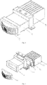
Fig. 6 is a perspective view of the light-emitting assembly according to an embodiment of the present invention; -
Fig. 7 is an exploded view of the light-emitting assembly according to an embodiment of the present invention; -
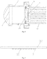
Fig. 8 is a cross-sectional view of the light-emitting assembly according to an embodiment of the present invention; -
Fig. 9 is a schematic structural diagram of the light source portion according to an embodiment of the present invention; -
Fig. 10 is a perspective view of the light-emitting system according to an embodiment of the present invention; -
Fig. 11 is an exploded view of the light-emitting system according to an embodiment of the present invention; -
Fig. 12 is an enlarged partial view of the housing according to an embodiment of the present invention. - 2 - secondary lens, 3 - light source portion, 4 - housing, 5 - heat dissipation portion, 31 - LED particle, 32 - circuit board, 41 - angle scale dial, 42 - angle pointer, 43 - mounting hole, 44 - arc-shaped hole, 51 - main plate portion, 52 - heat dissipation fin, 100 - primary lens, 110 - main body portion, 111 - first optical surface, 112 - second optical surface, 113 - focus line, 114 - ridge, 115 - arc-shaped concave surface, 116 - transition surface, 120 - flanged edge.
- It should be noted that the embodiments and the features in the embodiments can be combined freely, provided that there is no confliction among them.
- Hereunder the present invention will be detailed in embodiments with reference to the accompanying drawings.
- The present invention provides a
primary lens 100, which comprises amain body portion 110, which comprises a firstoptical surface 111 and a secondoptical surface 112, wherein alinear focus line 113 is formed on the firstoptical surface 111, and the height of the firstoptical surface 111 is gradually reduced from thefocus line 113 towards two sides; and the secondoptical surface 112 comprises a plurality ofridges 114 arranged in parallel and extending in a direction perpendicular to thefocus line 113, and theridges 114 have arc-shaped convex faces. - As shown in
Fig. 4 , thefocus line 113 is the peak portion on the firstoptical surface 111, and the portions of the firstoptical surface 111 at the two sides of thefocus line 113 are gradually reduced in height and turn into deformed convex surfaces; as shown inFigs. 3 and5 , the arc-shaped convex surface of theridge 114 may be regarded as a part of the circumferential surface of a cylindrical structure, and the extending direction of theridge 114 is parallel to the central axis of the cylindrical structure. - When the
primary lens 100 is applied to a headlight, theprimary lens 100 may be placed as follows: thefocus line 113 may extend substantially in the horizontal direction, and theridge 114 extends in the vertical direction. The light source may be placed on the side of the firstoptical surface 111, which may serve as an incident surface; the secondoptical surface 112 may serve as an emergent surface. The firstoptical surface 111 may cause the incident light to converge toward thecenter focus line 113 in the vertical direction, and the secondoptical surface 112 may cause the incident light to form emergent light diffused in the horizontal direction. That is to say, utilizing the first optical surface 11 and the secondoptical surface 112, the light beam generated by the light source can be converged in the vertical direction and diffused in the horizontal direction, which is more suitable for the characteristic of wider horizontal irradiation range and narrower vertical irradiation range of a headlight. - In addition,
adjacent ridges 114 smoothly transit via an arc-shapedconcave face 115. As shown inFig. 3 , theridge 114 itself is formed with an arc-shaped convex surface, and every two adjacent arc-shaped convex surfaces may be connected via an arc-shapedconcave surface 115 so as to realize smooth transition. That is say, the tangent line of the arc-shaped convex surface and the tangent line of the arc-shaped concave surface are coincident at the connection point. The central axis of the arc-shaped concave surface115 may be parallel to the central axis of the arc-shaped convex surface. Particularly, the diameter of the arc-shapedconcave surface 115 is much smaller than the diameter of the arc-shaped convex surface, i.e., the main body portion of the secondoptical surface 112 is an arc-shaped convex surface, and achieves diffusion of the light in the horizontal direction; the arc-shapedconcave surface 115 is only designed to connect two arc-shaped convex surfaces smoothly, the area ratio of the arc-shapedconcave surface 115 is negligible, and the optical effect of it is also negligible. - Furthermore, the arc-shaped convex faces of the
ridges 114 are identical, and theridges 114 are spaced apart evenly. The plurality ofridge 114 have consistent optical performance. In addition, since the secondoptical surface 112 is provided with the plurality ofridge 114, the radius of the arc-shaped convex surface is smaller than the dimension of the secondoptical surface 112 in the horizontal direction, so that the diffused light formed by the secondoptical surface 112 in the lateral direction is uniform. - Specifically, a sub-optical surface is formed respectively at each side of the
focus line 113 and comprises a plurality of convex arc-shaped surfaces, and the central axis of each of the arc-shaped surfaces is parallel to thefocus line 113. The arc-shaped surface may be regarded as a part of the circumferential surface of a cylinder with a central axis parallel to thefocus line 113, i.e., a cylindrical arc-shaped surface (similar to the arc-shaped convex surface of the ridge 114), and the firstoptical surface 111 is formed as an incident surface with a convex central portion (thefocus line 113 is convex), so that incident light beam can be converged in the vertical direction. - Particularly, the radii of the arc-shaped surfaces are increased sequentially in a direction from the
focus line 113 to either side in each of the sub-optical surfaces, and the plurality of arc-shaped surfaces are sequentially connected smoothly. The radius of the arc-shaped surface close to thefocus line 113 is smaller, while the radius of the arc-shaped surface away from thefocus line 113 is greater. Thus, adjacent arc-shaped surfaces can be smoothly connected, i.e., the tangent lines of adjacent arc-shaped surfaces coincide with each other at the connection point. At thefocus line 113, the two arc-shaped surfaces of the two sub-optical surfaces are connected to each other, and thefocus line 113 is at the highest position. - In addition, the two sub-optical surfaces are symmetric with respect to the
focus line 113. The two symmetrical sub-optical surfaces at the two sides of thefocus line 113 have the same light convergence ability, so that the light beam formed by convergence is more uniform in the vertical direction without obvious bright and dark areas. At thefocus line 113, the two arc-shaped surfaces of the two sub-optical surfaces with the same radius are connected to each other to form an arc-shaped surface with a greater angle, and thefocus line 113 is the highest generatrix on the arc-shaped surface. - In addition, the
main body portion 110 comprises transition surfaces 116 at the two ends of thefocus line 113, and the transition surfaces 116 are smoothly connected to the two sub-optical surfaces. As shown inFigs. 1 and4 , the function of thetransition surface 116 is to form smooth transition at the two ends of the firstoptical surface 111 to avoid sharp-angled transition and protect themain body portion 110. The effect of thetransition surface 116 on the light source may be negligible, or the light source may be arranged to be aligned with thefocus line 113, so that the emitted light is mainly incident on the firstoptical surface 111. - Furthermore, as shown in
Figs. 1 and 2 , theprimary lens 100 further comprises a fixedflanged edge 120 arranged around the edge of themain body portion 110, and through-holes are formed in the fixedflanged edge 120. The fixedflanged flange 120 may be used to assist in fixing theprimary lens 100 to prevent the related fixed structure from contacting with themain body portion 110 and affecting the function of themain body portion 110. - The
primary lens 100 may be made of any transparent and light-transmissive materials, such as glass, polycarbonate, polymethyl methacrylate, and the like. Preferably, theprimary lens 100 is made of silicone. Silicone has high light transmittance and excellent heat resistance properties. If the distance betweenprimary lens 100 and the light source is small, the temperature of theprimary lens 100 is high. A silicone lens has superior heat deformation resistance property, and is not aged into yellow color easily. - In addition, the invention provides a light-emitting assembly, which comprises a light source portion, a primary lens and a secondary lens, wherein the light generated by the light source portion sequentially passes through the primary lens and the secondary lens. The light generated by the light source portion may entry into the first
optical surface 111, exit from the secondoptical surface 112, and then pass through the secondary lens, which may be a convex lens for converging the light. Thefocus line 113 may extend horizontally in the lateral direction, and theridge 114 extends in the vertical direction. The light generated by the light source portion is converged toward thefocus line 113 in the vertical direction when it is transmitted through the firstoptical surface 111, and is diffused in the lateral direction at the secondoptical surface 112, and then is converged through thesecondary lens 2 that serves as a convex lens. - The present invention provides a light-emitting assembly, which comprises a
light source portion 3, aprimary lens 100 and asecondary lens 2 arranged sequentially in a first direction, wherein thelight source portion 3 comprises a plurality of lamps arranged in a second direction, theprimary lens 100 comprises a firstoptical surface 111 that faces thelight source portion 3 and a secondoptical surface 112 that faces thesecondary lens 2, alinear focus line 113 extending in the second direction is formed on the firstoptical surface 111, and the height of the firstoptical surface 111 is gradually reduced from thefocus line 113 to the two sides; the secondoptical surface 112 comprises a plurality ofridges 114 arranged in a third direction, and theridges 114 have arc-shaped convex faces; thesecondary lens 2 is a convex lens, and the third direction, the first direction, and the second direction are perpendicular to each other. - In the light-emitting assembly provided in the present invention, the
primary lens 100 may be theprimary lens 100 described in the above scheme. - The first direction, the second direction and the third direction may be regarded as the directions of three axes of a three-dimensional rectangular coordinate system, and the light-emitting assembly may be placed and used as follows: For example, when applied to the headlight of a vehicle, the first direction is the longitudinal direction, i.e., the front-rear direction of the vehicle, the second direction is the transverse direction, i.e., the left-right direction of the vehicle, and the third direction is the vertical direction. The light emitted from each of the lamps of the
light source portion 3 sequentially passes through theprimary lens 100 and thesecondary lens 2, wherein, as shown inFig. 4 , the firstoptical surface 111 of theprimary lens 100 is shaped to be higher at the center (at the focus line 113) and lower at the two sides, and can converge the incident light in the third direction; as shown inFigs. 3 and5 , the secondoptical surface 112 comprises a plurality of arc-shaped convex surfaces extending in the third direction, and can diffuse the emergent light in the second direction. The emergent light from the secondoptical surface 112 is converged when it passes through thesecondary lens 2 that is a convex lens. Particularly, the plurality of lamps on thelight source portion 3 are arranged in the second direction, and have different incident angles in the second direction. Therefore, light beams emitted through thesecondary lens 2 are at different angles, and the light spots formed by the light beams on the surface are aligned in the second direction. The light-emitting assembly may be applied to a headlight, wherein the second direction is a transverse direction, the third direction is a vertical direction, the irradiation range of the headlight is expanded in the transverse direction, and converged in the vertical direction, which is in line with the illumination characteristics of the headlight. The plurality of lamps on thelight source portion 3 may be arranged closely or spaced apart evenly in the second direction, and the plurality of lamps may be selectively turned on and off. For example, a light beam irradiated on pedestrians or vehicles in front of the vehicle may be selectively turned off to avoid glare to the pedestrians or vehicles. - The
secondary lens 2 is a convex lens, i.e., a lens that is thicker at the center and thinner at the edge, for example, a lens with convex spherical surfaces on both sides, which has a light convergence function. Specifically, as shown inFigs. 6, 7 , and8 , the incident surface of thesecondary lens 2 is a planar surface, and the emergent surface of thesecondary lens 2 is a spherical surface. The incident surface is formed as a planar surface. As described below, the light beams formed by lamps at different positions form included angles with each other. For different lamps arranged in the second direction, the included angles between the light beams with respect to the incident surface don't vary owing to thesecondary lens 2. - Specifically, the
light source portion 3 comprises acircuit board 32, and the lamps are LEDparticles 31 and arranged on thecircuit board 32. As shown inFig. 9 , theLED particles 31 may be disposed on thecircuit board 32 intermittently or continuously in the second direction (e.g., may be a lateral direction), the plurality ofLED particles 31 may be aligned to thefocus line 113 of theprimary lens 100, and eachLED particle 31 may be selectively turned on and off by a control circuit. The light beams formed by theLED particles 31 through theprimary lens 100 and thesecondary lens 2 may form a plurality of light spots arranged in the second direction in a plane to form an irradiation surface in the second direction, and one or more of theLED particles 31 may be selectively turned off, so that some irradiation positions can be avoided, such as the positions where pedestrians or vehicles are located (when the LED particles are applied to a headlight), and thereby glare resulted from irradiation of strong light on the pedestrians or vehicles can be avoided. - In addition, the
light source portion 3 comprises n lamps, the included angle of a light beam formed by any two adjacent lamps through theprimary lens 100 and thesecondary lens 2 is 2-3 degrees, and the angle of a light beam formed by n lamps is 2n-3n degrees. The included angles between the light beams formed by theLED particles 31 and the first direction are different from each other, and the plurality of light beams emitted from the plurality ofLED particles 31 form an irradiation range similar to a sector, the included angle between the light beams emitted from every twoadjacent LED particles 31 is 2-3 degrees, and the angle of the irradiation range of the entire sector is 2n-3n degrees. - Specifically, the arc-shaped convex faces are identical, and the
ridges 114 are spaced apart evenly. The plurality ofridge 114 have consistent optical performance. In addition, since the secondoptical surface 112 is provided with the plurality ofridge 114, the radius of the arc-shaped convex surface is so smaller with respect to the dimension of the secondoptical surface 112 in the horizontal direction that the diffused light formed by the secondoptical surface 112 in the lateral direction is uniform. - Furthermore,
adjacent ridges 114 smoothly transit via an arc-shapedconcave face 115. Theridge 114 itself is formed with an arc-shaped convex surface, and every two adjacent arc-shaped convex surfaces may be connected via an arc-shapedconcave surface 115 so as to realize smooth transition. That is say, the tangent line of the arc-shaped convex surface and the tangent line of the arc-shaped concave surface are coincident at the connection point. The central axis of the arc-shapedconcave surface 115 may be parallel to the central axis of the arc-shaped convex surface. Particularly, the diameter of the arc-shapedconcave surface 115 is much smaller than the diameter of the arc-shaped convex surface, i.e., the main body portion of the secondoptical surface 112 is an arc-shaped convex surface, and achieves diffusion of the light in the horizontal direction; the arc-shapedconcave surface 115 is only designed to connect two arc-shaped convex surfaces smoothly, the area ratio of the arc-shaped concave surface 115is negligible, and the optical effect of it is also negligible. - In addition, a sub-optical surface is formed respectively at each sideof the
focus line 113 and comprises a plurality of convex arc-shaped surfaces, and the central axis of each of the arc-shaped surfaces is parallel to thefocus line 113. The arc-shaped surface may be regarded as a part of the circumferential surface of a cylinder with a central axis parallel to thefocal line 113, i.e., a cylindrical arc-shaped surface (similar to the arc-shaped convex surface of the ridge 114), and the firstoptical surface 111 is formed as an incident surface with a convex central portion (thefocus line 113 is convex), so that incident light beam can be converged in the vertical direction. - Furthermore, the radii of the arc-shaped surfaces are increased sequentially in a direction from the
focus line 113 to either side in each of the sub-optical surfaces, and the plurality of arc-shaped surfaces are sequentially connected smoothly. The radius of the arc-shaped surface close to thefocus line 113 is smaller, while the radius of the arc-shaped surface away from thefocus line 113 is greater. Thus, adjacent arc-shaped surfaces can be smoothly connected, i.e., the tangent lines of adjacent arc-shaped surfaces coincide with each other at the connection point. At thefocus line 113, the two arc-shaped surfaces of the two sub-optical surfaces are connected to each other, and thefocus line 113 is at the highest position. - In addition, each of the light-emitting assemblies comprises a
housing 4 having a light passage, theprimary lens 100 is arranged at an entry end of thehousing 4, and thesecondary lens 2 is arranged at an exit end of thehousing 4. As shown inFigs. 6, 7 and8 , thehousing 4 is generally formed into a tubular shape. Of course, the cross section of thehousing 4 may be quadrangular, circular, triangular, etc., and is preferably quadrangular to accommodate the shape of theprimary lens 100. Accordingly, thesecondary lens 2 may also have a generally quadrangular shape. - In addition, the light-emitting assembly comprises a
heat dissipation portion 5 engaged with thelight source portion 3, theheat dissipation portion 5 comprises amain plate portion 51 attached to thelight source portion 3 andheat dissipation fins 52 provided on themain plate portion 51, and themain plate portion 51 sealingly blocks the entry end of thehousing 4. The lamps of thelight source portion 3 generate great heat when they emit light. For example, LED particles generate heat when they emit light. The heat is transferred to the circuit board. Therefore, aheat dissipation portion 5 attached to the circuit board may be provided, with amain plate portion 51 attached to the circuit board for blocking the entry end of thehousing 4, so that the interior of thehousing 4 is hermetically sealed and isolated from the exterior. A boss may be provided on the surface of themain plate portion 51 attached to thelight source portion 3. Theprimary lens 100 is mounted on the boss via a mounting structure to keep clearance from thelight source portion 3. Theprimary lens 100 is located inside thehousing 4 and isolated from the exterior to prevent theprimary lens 100 from corroded and damaged. - The present invention provides a light-emitting system, which comprises a plurality of light-emitting assemblies, each of which comprises a
light source portion 3, aprimary lens 100 and asecondary lens 2 sequentially arranged in a first direction, wherein thelight source portion 3 comprises a plurality of lamps spaced apart in a second direction; the plurality of light-emitting assemblies are arranged in a third direction, and can rotate with respect to each other around an axis in the third direction; the first direction, the second direction, and the third direction are perpendicular to each other; theprimary lens 100 comprises a firstoptical surface 111 that faces thelight source portion 3 and a secondoptical surface 112 that faces thesecondary lens 2, alinear focus line 113 extending in the second direction is formed on the firstoptical surface 111, the height of the firstoptical surface 111 is gradually reduced from thefocus line 113 to the two sides, the secondoptical surface 112 comprises a plurality ofridges 114 extending in the third direction and having arc-shaped convex surfaces, and thesecondary lens 2 is a convex lens. - In the light-emitting system provided in the present invention, the light-emitting assembly may be the light-emitting assembly described in the above scheme.
- The first direction, the second direction and the third direction may be regarded as the directions of three axes of a three-dimensional rectangular coordinate system, and the light-emitting assembly may be placed and used as follows: For example, when applied to the headlight of a vehicle, the third direction is the vertical direction, the first direction is the longitudinal direction, i.e., the front-rear direction of the vehicle, and the second direction is the transverse direction, i.e., the left-right direction of the vehicle. It should be noted that the first direction and the second direction are defined for a single light-emitting assembly. Since the light-emitting assemblies can rotate around an axis in the third direction, there are included angles between the first directions of the light-emitting assemblies and included angles between the second directions of the light-emitting assemblies. However, the included angles are relatively small. After the light-emitting system is installed in a vehicle, it may be deemed that the first directions of the light-emitting assemblies are the same direction, i.e., the front-rear direction of the vehicle, and the second directions of the light-emitting assemblies are also the same direction, i.e., the left-right direction of the vehicle.
- In each light-emitting assembly, the light emitted from each of the lamps of the
light source portion 3 sequentially passes through theprimary lens 100 and thesecondary lens 2, wherein, as shown inFig. 4 , the firstoptical surface 111 of theprimary lens 100 is shaped to be higher at the center (at the focus line 113) and lower at the two sides, and can converge the incident light in the third direction; as shown inFigs. 3 and5 , the secondoptical surface 112 comprises a plurality of arc-shaped convex surfaces extending in the third direction, and can diffuse the emergent light in the second direction. The emergent light from the secondoptical surface 112 is converged when it passes through thesecondary lens 2 that is a convex lens. Particularly, the plurality of lamps on thelight source portion 3 are arranged in the second direction, and have different incident angles in the second direction. Therefore, light beams emitted through thesecondary lens 2 are at different angles, and the light spots formed by the light beams on the surface are arranged in the second direction. The light-emitting assembly may be applied to a headlight, wherein the second direction is a transverse direction, the third direction is a vertical direction, the irradiation range of the headlight is expanded in the transverse direction, and converged in the vertical direction, which is in line with the illumination characteristics of the headlight. - Particularly, in each light-emitting assembly, the lamps are arranged at an interval, in view that the lamps generate heat when they emit light. By arranging the lamps at an interval, the heat dissipation effect can be improved, and damage to the
light source portion 3 resulted from high temperature can be avoided. Accordingly, in the irradiation surface formed by each light-emitting assembly, there is a dark area between two adjacent light spots formed by two lamps. Therefore, in the scheme, a plurality of light-emitting assemblies capable of rotating around an axis in the vertical direction are arranged in the third direction (i.e., the vertical direction), wherein a plurality of groups of light spots formed by the plurality of light-emitting assemblies are crossed and staggered from each other, so that the dark area of each light-emitting assembly is filled by the light spots of other light-emitting assemblies, and thus the dark area can be eliminated. It should be noted that although the plurality of light-emitting assemblies are staggered in the third direction, the light spots formed by the light-emitting assemblies can be expanded in the third direction, so that the light spots formed by the plurality of light-emitting assemblies can cross each other. - In addition, each of the light-emitting assemblies comprises a
housing 4 having a light passage, theprimary lens 100 is arranged at an entry end of thehousing 4, and thesecondary lens 2 is arranged at an exit end of thehousing 4. Theprimary lens 100 and thesecondary lens 2 are supported by thehousing 4, wherein, as shown inFigs. 8 ,10 ,11 and 12 , thehousing 4 is generally formed into a tubular shape. Of course, alternatively the cross section of thehousing 4 may be quadrangular, circular, triangular, etc., and is preferably quadrangular to accommodate the shape of theprimary lens 100. Accordingly, thesecondary lens 2 may also have a generally quadrangular shape. Furthermore, the light-emitting system comprises two light-emitting assemblies, wherein onehousing 4 is provided with a cylindrical boss extending in the third direction, theother housing 4 is provided with a circular hole for accommodating the cylindrical boss to be inserted, and the twohousings 4 can rotate with respect to each other; wherein onehousing 4 is provided with anangle scale dial 41, and theother housing 4 is provided with anangle pointer 42 corresponding to theangle scale dial 41; and wherein onehousing 4 is provided with a mountinghole 43, theother housing 4 is provided with an arc-shapedhole 44 extending around the central axis of the cylindrical boss, and the twohousings 4 are fixed by a connecting member penetrating through the mountinghole 43 and the arc-shapedhole 44. For thelight source portion 3 of each light-emitting assembly, when the distance between two adjacent lamps is small, the distance between the two light spots formed by the two adjacent lamps is also small, especially smaller than the size of one light spot. Therefore, only two light-emitting assemblies are required to be complementary to each other to fill the dark area between the light spots. Thehousings 4 of two light-emitting assemblies can rotate around an axis in the third direction to adjust the relative angle between them, so that the light spots formed by the two light-emitting assemblies are staggered with each other and complement each other to fill the dark area between the light spots. In addition, as shown inFig. 12 , the two housings are further provided with an angle display mechanism. The angle indicated by anangle pointer 42 on theangle scale dial 41 may be utilized directly by other optical systems, thus the operation of readjusting the relative angle of the twohousings 4 can be omitted. In addition, when the twohousings 4 rotate with respect to each other, the mountingholes 43 are aligned with different positions of the arc-shapedholes 44, and the twohousings 4 may be fixed with respect to each other by means of connecting members, such as bolts, nuts, etc. - In addition, the light-emitting assembly comprises a
heat dissipation portion 5 engaged with thelight source portion 3, theheat dissipation portion 5 comprises amain plate portion 51 attached to thelight source portion 3 andheat dissipation fins 52 provided on themain plate portion 51, and themain plate portion 51 sealingly blocks the entry end of thehousing 4. The lamps of thelight source unit 3 generate great height when they emit light. For example, LED particles generate heat when they emit light. The heat is transferred to the circuit board. Therefore, aheat dissipation unit 5 attached to the circuit board may be provided. In addition, in the scheme, a light source is provided by means of a plurality oflight source portions 3 of a plurality of light-emitting assemblies, and a plurality of lamps are distributed on (the circuit board of) differentlight source portions 3, thereby the problem of excessively concentrated heat generation by lamps arranged closely can be avoided. Amain plate portion 51 is attached to the circuit board, and configured to block the entry end of thehousing 4, so that the interior of thehousing 4 is sealed and isolated from the exterior. A boss may be provided on the surface of themain body plate 51 attached to thelight source portion 3. Theprimary lens 100 is mounted on the boss via a mounting structure to keep clearance from thelight source portion 3. Theprimary lens 100 is located inside thehousing 4 and isolated from the exterior to prevent theprimary lens 100 from being corroded and damaged. - The
secondary lens 2 is a convex lens, i.e., a lens that is thicker at the center and thinner at the edge, for example, a lens with convex spherical surfaces on both sides, which has a light convergence function. Specifically, the incident face of thesecondary lens 2 is a planar face, and the emergent face of thesecondary lens 2 is a spherical face. The incident surface is formed as a planar surface. As described below, the light beams formed by lamps at different positions form included angles with each other. For different lamps arranged in the first direction, the included angles between the light beams with respect to the incident surface don't vary owing to thesecondary lens 2. Specifically, the radii of the arc-shaped convex surfaces are identical, theridges 114 are spaced apart evenly, andadjacent ridges 114 smoothly transit via an arc-shapedconcave surface 115. The plurality ofridges 114 have consistent optical performance. In addition, since the secondoptical surface 112 is provided with the plurality ofridge 114, the radius of the arc-shaped convex surface is smaller than the dimension of the secondoptical surface 112 in the horizontal direction, so that the diffused light formed by the secondoptical surface 112 in the lateral direction is uniform. Theridge 114 itself is formed with an arc-shaped convex surface, and every two adjacent arc-shaped convex surfaces may be connected via an arc-shapedconcave surface 115 so as to realize smooth transition. That is say, the tangent line of the arc-shaped convex surface and the tangent line of the arc-shaped concave surface are coincident at the connection point. The central axis of the arc-shapedconcave surface 115 may be parallel to the central axis of the arc-shaped convex surface. Particularly, the diameter of the arc-shapedconcave surface 115 is much smaller than the diameter of the arc-shaped convex surface, i.e., the main body portion of the secondoptical surface 112 is an arc-shaped convex surface, and achieves diffusion of the light in the horizontal direction; the arc-shapedconcave surface 115 is only designed to connect two arc-shaped convex surfaces smoothly, the area ratio of the arc-shapedconcave surface 115 is negligible, and the optical effect of it is also negligible. - In addition, a sub-optical surface is formed respectively at each side of the
focus line 113 and comprises a plurality of convex arc-shaped surfaces, and the central axis of each of the arc-shaped surfaces is parallel to thefocus line 113. The arc-shaped surface may be regarded as a part of the circumferential surface of a cylinder with a central axis parallel to thefocal line 113, i.e., a cylindrical arc-shaped surface (similar to the arc-shaped convex surface of the ridge 114), and the firstoptical surface 111 is formed as an incident surface with a convex central portion (thefocus line 113 is convex), so that incident light beam can be converged in the vertical direction. - Furthermore, the radii of the arc-shaped surfaces are increased sequentially in a direction from the
focus line 113 to either side in each of the sub-optical surfaces, and the plurality of arc-shaped surfaces are sequentially connected smoothly. The radius of the arc-shaped surface close to thefocus line 113 is smaller, while the radius of the arc-shaped surface away from thefocus line 113 is greater. Thus, adjacent arc-shaped surfaces can be smoothly connected, i.e., the tangent lines of adjacent arc-shaped surfaces coincide with each other at the connection point. At thefocus line 113, the two arc-shaped surfaces of the two sub-optical surfaces are connected to each other, and thefocus line 113 is at the highest position. - Specifically, as shown in
Fig. 9 , thelight source portion 3 comprises acircuit board 32 and n lamps, the lamps are LEDparticles 31, the included angle of a light beam formed by any two adjacent lamps through theprimary lens 100 and thesecondary lens 2 is 2-3 degrees, and the angle of a light beam formed by n lamps is 2n-3n degrees. The included angles between the light beams formed by theLED particles 31 and the third direction are different from each other, and the plurality of light beams emitted from the plurality ofLED particles 31 form an irradiation range similar to a sector, the included angle between the light beams emitted from every twoadjacent LED particles 31 is 2-3 degrees, and the angle of the irradiation range of the entire sector is 2n-3n degrees. - In another aspect, the present invention provides a headlight, which is provided with the light-emitting system described in the above scheme. When the light-emitting system is installed in a vehicle, the third direction is the vertical direction, the first direction is the front-rear direction of the vehicle, and the second direction is the left-right direction of the vehicle, and the angles between the light-emitting assemblies are fixed. In addition, the headlight may be provided with other control devices to cooperate with the light-emitting system. For example, a light sensor may be provided to sense the light reflected by obstacles (e.g., pedestrians, vehicles, etc.) in front of the vehicle and judge the positions of the obstacles, so that the lamps corresponding to the obstacles can be turned off and glare resulted from light irradiation on the pedestrians and vehicles can be avoided.
- While the present invention is described above in some preferred embodiments, the present invention is not limited to those preferred embodiments. Any modification, equivalent replacement, and improvement made without departing from the spirit and principle of the present invention shall be deemed as falling into the scope of protection of the present invention.
Claims (29)
- A primary lens (100), comprising a main body portion (110), which comprises a first optical surface (111) and a second optical surface (112), wherein a linear focus line (113) is formed on the first optical surface (111), and the height of the first optical surface (111) is gradually reduced from the focus line (113) towards two sides; and the second optical surface (112) comprises a plurality of ridges (114) arranged in parallel and extending in a direction perpendicular to the focus line (113), and the ridges (114) have arc-shaped convex faces.
- The primary lens according to claim 1, wherein adjacent ridges (114) smoothly transit via an arc-shaped concave face (115).
- The primary lens according to claim 2, wherein the arc-shaped convex faces of the ridges (114) are identical, and the ridges (114) are spaced apart evenly.
- The primary lens according to claim 1, wherein a sub-optical surface is formed respectively at each side of the focus line (113) and comprises a plurality of convex arc-shaped surfaces, and the central axis of each of the arc-shaped surfaces is parallel to the focus line (113).
- The primary lens according to claim 4, wherein the radii of the arc-shaped surfaces are increased sequentially in a direction from the focus line (113) to either side in each of the sub-optical surfaces, and the plurality of arc-shaped surfaces are sequentially connected smoothly.
- The primary lens according to claim 4, wherein the two sub-optical surfaces are symmetric with respect to the focus line (113).
- The primary lens according to claim 4, wherein the main body portion (110) comprises transition surfaces (116) at the two ends of the focus line (113), and the transition surfaces (116) are smoothly connected to the two sub-optical surfaces.
- The primary lens (100) according to claim 1, further comprising a fixed flanged edge (120) arranged around the edge of the main body portion (110), with through-holes formed in the fixed flanged edge (120).
- The primary lens (100) according to any of claims 1-8, made of silicone.
- A light-emitting assembly, comprising a light source portion (3), a primary lens (100) and a secondary lens (2) arranged sequentially in a first direction, wherein the light source portion (3) comprises a plurality of lamps arranged in a second direction, the primary lens (100) comprises a first optical surface (111) that faces the light source portion (3) and a second optical surface (112) that faces the secondary lens (2), a linear focus line (113) extending in the second direction is formed on the first optical surface (111), and the height of the first optical surface (111) is gradually reduced from the focus line (113) to the two sides; the second optical surface (112) comprises a plurality of ridges (114) arranged in a third direction, and the ridges (114) have arc-shaped convex faces; the secondary lens (2) is a convex lens, and the third direction, the first direction, and the second direction are perpendicular to each other.
- The light-emitting assembly according to claim 10, wherein the incident face of the secondary lens (2) is a planar face, and the emergent face of the secondary lens (2) is a spherical face.
- The light-emitting assembly according to claim 10, wherein the light source portion (3) comprises a circuit board (32), and the lamps are LED particles (31) and arranged on the circuit board (32).
- The light-emitting assembly according to claim 12, wherein the light source portion (3) comprises n lamps, the included angle of a light beam formed by any two adjacent lamps through the primary lens (100) and the secondary lens (2) is 2-3 degrees, and the angle of a light beam formed by n lamps is 2n-3n degrees.
- The light-emitting assembly according to claim 10, wherein the radii of the arc-shaped convex faces are identical, and the ridges (114) are spaced apart evenly.
- The light-emitting assembly according to claim 14, wherein adjacent ridges smoothly transit via an arc-shaped concave face (115).
- The light-emitting assembly according to claim 10, wherein a sub-optical surface is formed respectively at each side of the focus line (113) and comprises a plurality of convex arc-shaped surfaces, and the central axis of each of the arc-shaped surfaces is parallel to the focus line (113).
- The light-emitting assembly according to claim 16, wherein the radii of the arc-shaped surfaces are increased sequentially in a direction from the focus line (113) to either side in each of the sub-optical surfaces, and the plurality of arc-shaped surfaces are sequentially connected smoothly.
- The light-emitting assembly according to any of claims 10-17, comprising a housing (4) having a light passage, the primary lens (100) is arranged at an entry end of the housing (4), and the secondary lens (2) is arranged at an exit end of the housing (4).
- The light-emitting assembly according to claim 18, comprising a heat dissipation portion (5) engaged with the light source portion (3), wherein the heat dissipation portion (5) comprises a main plate portion (51) attached to the light source portion (3) and heat dissipation fins (52) provided on the main plate portion (51), and the main plate portion (51) sealingly blocks the entry end of the housing (4).
- A light-emitting system, comprising a plurality of light-emitting assemblies, each of which comprises a light source portion (3), a primary lens (100) and a secondary lens (2) sequentially arranged in a first direction, wherein the light source portion (3) comprises a plurality of lamps spaced apart in a second direction; the plurality of light-emitting assemblies are arranged in a third direction, and can rotate with respect to each other around an axis in the third direction; the first direction, the second direction, and the third direction are perpendicular to each other; the primary lens (100) comprises a first optical surface (111) that faces the light source portion (3) and a second optical surface (112) that faces the secondary lens (2), a linear focus line (113) extending in the second direction is formed on the first optical surface (111), the height of the first optical surface (111) is gradually reduced from the focus line (113) to the two sides, the second optical surface (112) comprises a plurality of ridges (114) extending in the third direction and having arc-shaped convex surfaces, and the secondary lens (2) is a convex lens.
- The light-emitting system according to claim 20, wherein each of the light-emitting assemblies comprises a housing (4) having a light passage, the primary lens (100) is arranged at an entry end of the housing (4), and the secondary lens (2) is arranged at an exit end of the housing (4).
- The light-emitting system according to claim 21, comprising two light-emitting assemblies,
wherein one housing (4) is provided with a cylindrical boss extending in the third direction, the other housing (4) is provided with a circular hole for accommodating the cylindrical boss to be inserted, and the two housings (4) can rotate with respect to each other,
wherein one housing (4) is provided with an angle scale dial (41), and the other housing (4) is provided with an angle pointer (42) corresponding to the angle scale dial (41),
wherein one housing (4) is provided with a mounting hole (43), the other housing (4) is provided with an arc-shaped hole (44) extending around the central axis of the cylindrical boss, and the two housings (4) are fixed by a connecting member penetrating through the mounting hole (43) and the arc-shaped hole (44). - The light-emitting system according to claim 21, wherein the light-emitting assembly comprises a heat dissipation portion (5) engaged with the light source portion (3), the heat dissipation portion (5) comprises a main plate portion (51) attached to the light source portion (3) and heat dissipation fins (52) provided on the main plate portion (51), and the main plate portion (51) sealingly blocks the entry end of the housing (4).
- The light-emitting system according to claim 20, wherein the incident face of the secondary lens (2) is a planar face, and the emergent face of the secondary lens (2) is a spherical face.
- The light-emitting system according to claim 20, wherein the radii of the arc-shaped convex surfaces are identical, the ridges (114) are spaced apart evenly, and adjacent ridges (114) smoothly transit via an arc-shaped concave surface (115).
- The light-emitting system according to claim 25, wherein a sub-optical surface is formed respectively at each side of the focus line (113) and comprises a plurality of convex arc-shaped surfaces, and the central axis of each of the arc-shaped surfaces is parallel to the focus line (113).
- The light-emitting system according to claim 26, wherein the radii of the arc-shaped surfaces are increased sequentially in a direction from the focus line (113) to either side in each of the sub-optical surfaces, and the plurality of arc-shaped surfaces are sequentially connected smoothly.
- The light-emitting system according to any of claims 20-27, wherein the light source portion (3) comprises a circuit board (32) and n lamps, the lamps are LED particles (31), the included angle of a light beam formed by any two adjacent lamps through the primary lens (100) and the secondary lens (2) is 2-3 degrees, and the angle of a light beam formed by n lamps is 2n-3n degrees.
- A headlight provided with the light-emitting system according to any of claims 20 to 28.
Applications Claiming Priority (4)
| Application Number | Priority Date | Filing Date | Title |
|---|---|---|---|
| CN201710936654.9A CN108870308B (en) | 2017-10-10 | 2017-10-10 | Lighting components |
| CN201710936611.0A CN108800045B (en) | 2017-10-10 | 2017-10-10 | Light emitting system and vehicle lamp |
| CN201710935527.7A CN108826216A (en) | 2017-10-10 | 2017-10-10 | Lens and luminescence component |
| PCT/CN2018/109506 WO2019072174A1 (en) | 2017-10-10 | 2018-10-09 | Primary lens, light-emitting assembly, light-emitting system, and headlight |
Publications (3)
| Publication Number | Publication Date |
|---|---|
| EP3677829A1 true EP3677829A1 (en) | 2020-07-08 |
| EP3677829A4 EP3677829A4 (en) | 2020-10-14 |
| EP3677829B1 EP3677829B1 (en) | 2023-08-09 |
Family
ID=66100426
Family Applications (1)
| Application Number | Title | Priority Date | Filing Date |
|---|---|---|---|
| EP18866727.3A Active EP3677829B1 (en) | 2017-10-10 | 2018-10-09 | Primary lens, light-emitting assembly, light-emitting system, and headlight |
Country Status (3)
| Country | Link |
|---|---|
| EP (1) | EP3677829B1 (en) |
| RU (1) | RU2737848C1 (en) |
| WO (1) | WO2019072174A1 (en) |
Cited By (3)
| Publication number | Priority date | Publication date | Assignee | Title |
|---|---|---|---|---|
| WO2023275055A1 (en) * | 2021-07-01 | 2023-01-05 | Valeo Vision | Motor vehicle light module comprising a low wall for positioning and/or attaching an optical device |
| EP4290127A4 (en) * | 2021-08-12 | 2024-05-29 | Hasco Vision Technology Co., Ltd. | Vehicle pixelated lighting device, vehicle lamp, and vehicle |
| WO2024175414A1 (en) * | 2023-02-22 | 2024-08-29 | Valeo Vision | Lighting device |
Families Citing this family (1)
| Publication number | Priority date | Publication date | Assignee | Title |
|---|---|---|---|---|
| CN112413530A (en) * | 2019-08-23 | 2021-02-26 | 华域视觉科技(上海)有限公司 | Miniature car light module |
Family Cites Families (16)
| Publication number | Priority date | Publication date | Assignee | Title |
|---|---|---|---|---|
| US5813743A (en) * | 1995-03-27 | 1998-09-29 | Fuji Photo Film Co., Ltd. | Lighting unit |
| US5692827A (en) * | 1996-03-01 | 1997-12-02 | Ford Motor Company | Tail lamp for an automotive vehicle using an elongated hyperbolic cylinder |
| JP2007048470A (en) * | 2005-08-05 | 2007-02-22 | Koito Mfg Co Ltd | Vehicle lighting |
| JP4782064B2 (en) * | 2007-04-10 | 2011-09-28 | 株式会社小糸製作所 | Vehicle lamp unit |
| JP5304363B2 (en) * | 2009-03-18 | 2013-10-02 | 市光工業株式会社 | Vehicle lighting |
| RU2398995C1 (en) * | 2009-03-27 | 2010-09-10 | Учреждение Российской академии наук Институт проблем управления им. В.А. Трапезникова РАН | Automotive led lamp |
| US9133999B2 (en) * | 2012-03-19 | 2015-09-15 | Ichikoh Industries, Ltd. | Vehicle headlamp |
| CN103968326B (en) * | 2013-01-31 | 2018-04-24 | 欧司朗有限公司 | Lens and the lighting device with the lens |
| CN203605147U (en) * | 2013-09-13 | 2014-05-21 | 东莞市欧科光电科技有限公司 | Concave Stripe Lens |
| CN203868944U (en) * | 2014-05-23 | 2014-10-08 | 刘炜斌 | Optical lens with stripes |
| DE102014118745B4 (en) * | 2014-12-16 | 2022-03-17 | HELLA GmbH & Co. KGaA | headlights for vehicles |
| FR3039630A1 (en) * | 2015-07-28 | 2017-02-03 | Valeo Vision | LIGHTING SYSTEM FOR MOTOR VEHICLE PROJECTOR |
| AT518098B1 (en) * | 2015-12-17 | 2017-11-15 | Zkw Group Gmbh | Additional headlights for vehicles and headlight system |
| CN108779904B (en) * | 2016-03-17 | 2020-12-25 | 本田技研工业株式会社 | Vehicle lamp |
| KR102460854B1 (en) * | 2016-05-17 | 2022-10-31 | 현대모비스 주식회사 | vehicle lamp |
| CN207198431U (en) * | 2017-10-10 | 2018-04-06 | 长城汽车股份有限公司 | The mounting structure of lens |
-
2018
- 2018-10-09 RU RU2020115085A patent/RU2737848C1/en active
- 2018-10-09 EP EP18866727.3A patent/EP3677829B1/en active Active
- 2018-10-09 WO PCT/CN2018/109506 patent/WO2019072174A1/en not_active Ceased
Cited By (5)
| Publication number | Priority date | Publication date | Assignee | Title |
|---|---|---|---|---|
| WO2023275055A1 (en) * | 2021-07-01 | 2023-01-05 | Valeo Vision | Motor vehicle light module comprising a low wall for positioning and/or attaching an optical device |
| FR3124846A1 (en) * | 2021-07-01 | 2023-01-06 | Valeo Vision | Motor vehicle light module comprising a low wall for positioning and/or fixing an optical device |
| US12281769B2 (en) | 2021-07-01 | 2025-04-22 | Valeo Vision | Motor vehicle light module comprising a low wall for positioning and/or attaching an optical device |
| EP4290127A4 (en) * | 2021-08-12 | 2024-05-29 | Hasco Vision Technology Co., Ltd. | Vehicle pixelated lighting device, vehicle lamp, and vehicle |
| WO2024175414A1 (en) * | 2023-02-22 | 2024-08-29 | Valeo Vision | Lighting device |
Also Published As
| Publication number | Publication date |
|---|---|
| WO2019072174A1 (en) | 2019-04-18 |
| RU2737848C1 (en) | 2020-12-03 |
| EP3677829B1 (en) | 2023-08-09 |
| EP3677829A4 (en) | 2020-10-14 |
Similar Documents
| Publication | Publication Date | Title |
|---|---|---|
| EP4148322B1 (en) | Vehicle lamp module | |
| JP6516495B2 (en) | Vehicle lamp | |
| EP3677829B1 (en) | Primary lens, light-emitting assembly, light-emitting system, and headlight | |
| CN103256546A (en) | Light module for dazzling-free headlight of motor car | |
| CN115066581A (en) | Lamp unit | |
| EP3754253B1 (en) | Light beam adjusting device, optical assembly and lighting and/or signaling apparatus | |
| US8439538B2 (en) | Vehicle light | |
| CN112135997B (en) | Matrix car light optical device, car light and vehicle | |
| JP2020187936A (en) | Vehicular lighting fixture | |
| JP7407668B2 (en) | lighting unit | |
| CN108800045B (en) | Light emitting system and vehicle lamp | |
| CN113864732A (en) | Uniform light emitting optical system and warning lamp | |
| CN221171904U (en) | Light emitting component, light emitting device and vehicle | |
| US11168859B2 (en) | Automotive lighting system for vehicles | |
| JP7784851B2 (en) | Vehicle lamp and automobile including same | |
| JP2021051897A (en) | Illuminating device | |
| CN207198431U (en) | The mounting structure of lens | |
| CN215372307U (en) | Lighting module, lighting device and vehicle | |
| US20180023783A1 (en) | Method and apparatus for subtending light downwardly | |
| US12196388B2 (en) | Light-emitting device, vehicle lamp and vehicle | |
| ES249300U (en) | Rear fog lamp for motor vehicles | |
| CN222210032U (en) | Short-focus lamplight module and vehicle | |
| CN217131127U (en) | Polarized light bicycle lamp | |
| CN218268854U (en) | Car light module, car light and automobile | |
| CN108870308B (en) | Lighting components |
Legal Events
| Date | Code | Title | Description |
|---|---|---|---|
| STAA | Information on the status of an ep patent application or granted ep patent |
Free format text: STATUS: THE INTERNATIONAL PUBLICATION HAS BEEN MADE |
|
| PUAI | Public reference made under article 153(3) epc to a published international application that has entered the european phase |
Free format text: ORIGINAL CODE: 0009012 |
|
| STAA | Information on the status of an ep patent application or granted ep patent |
Free format text: STATUS: REQUEST FOR EXAMINATION WAS MADE |
|
| 17P | Request for examination filed |
Effective date: 20200331 |
|
| AK | Designated contracting states |
Kind code of ref document: A1 Designated state(s): AL AT BE BG CH CY CZ DE DK EE ES FI FR GB GR HR HU IE IS IT LI LT LU LV MC MK MT NL NO PL PT RO RS SE SI SK SM TR |
|
| AX | Request for extension of the european patent |
Extension state: BA ME |
|
| A4 | Supplementary search report drawn up and despatched |
Effective date: 20200915 |
|
| RIC1 | Information provided on ipc code assigned before grant |
Ipc: F21S 41/29 20180101ALI20200909BHEP Ipc: F21S 41/25 20180101AFI20200909BHEP Ipc: F21S 41/255 20180101ALI20200909BHEP Ipc: F21S 41/20 20180101ALI20200909BHEP Ipc: F21S 41/151 20180101ALI20200909BHEP Ipc: F21S 41/141 20180101ALI20200909BHEP Ipc: F21W 107/10 20180101ALI20200909BHEP Ipc: F21S 45/47 20180101ALI20200909BHEP Ipc: F21S 41/143 20180101ALI20200909BHEP Ipc: F21W 102/13 20180101ALI20200909BHEP |
|
| DAV | Request for validation of the european patent (deleted) | ||
| DAX | Request for extension of the european patent (deleted) | ||
| STAA | Information on the status of an ep patent application or granted ep patent |
Free format text: STATUS: EXAMINATION IS IN PROGRESS |
|
| 17Q | First examination report despatched |
Effective date: 20220811 |
|
| GRAP | Despatch of communication of intention to grant a patent |
Free format text: ORIGINAL CODE: EPIDOSNIGR1 |
|
| STAA | Information on the status of an ep patent application or granted ep patent |
Free format text: STATUS: GRANT OF PATENT IS INTENDED |
|
| INTG | Intention to grant announced |
Effective date: 20230317 |
|
| GRAS | Grant fee paid |
Free format text: ORIGINAL CODE: EPIDOSNIGR3 |
|
| GRAA | (expected) grant |
Free format text: ORIGINAL CODE: 0009210 |
|
| STAA | Information on the status of an ep patent application or granted ep patent |
Free format text: STATUS: THE PATENT HAS BEEN GRANTED |
|
| AK | Designated contracting states |
Kind code of ref document: B1 Designated state(s): AL AT BE BG CH CY CZ DE DK EE ES FI FR GB GR HR HU IE IS IT LI LT LU LV MC MK MT NL NO PL PT RO RS SE SI SK SM TR |
|
| P01 | Opt-out of the competence of the unified patent court (upc) registered |
Effective date: 20230701 |
|
| REG | Reference to a national code |
Ref country code: GB Ref legal event code: FG4D |
|
| REG | Reference to a national code |
Ref country code: CH Ref legal event code: EP |
|
| REG | Reference to a national code |
Ref country code: DE Ref legal event code: R096 Ref document number: 602018055197 Country of ref document: DE |
|
| REG | Reference to a national code |
Ref country code: IE Ref legal event code: FG4D |
|
| REG | Reference to a national code |
Ref country code: LT Ref legal event code: MG9D |
|
| REG | Reference to a national code |
Ref country code: NL Ref legal event code: MP Effective date: 20230809 |
|
| REG | Reference to a national code |
Ref country code: AT Ref legal event code: MK05 Ref document number: 1597913 Country of ref document: AT Kind code of ref document: T Effective date: 20230809 |
|
| PG25 | Lapsed in a contracting state [announced via postgrant information from national office to epo] |
Ref country code: GR Free format text: LAPSE BECAUSE OF FAILURE TO SUBMIT A TRANSLATION OF THE DESCRIPTION OR TO PAY THE FEE WITHIN THE PRESCRIBED TIME-LIMIT Effective date: 20231110 |
|
| PG25 | Lapsed in a contracting state [announced via postgrant information from national office to epo] |
Ref country code: IS Free format text: LAPSE BECAUSE OF FAILURE TO SUBMIT A TRANSLATION OF THE DESCRIPTION OR TO PAY THE FEE WITHIN THE PRESCRIBED TIME-LIMIT Effective date: 20231209 |
|
| PG25 | Lapsed in a contracting state [announced via postgrant information from national office to epo] |
Ref country code: SE Free format text: LAPSE BECAUSE OF FAILURE TO SUBMIT A TRANSLATION OF THE DESCRIPTION OR TO PAY THE FEE WITHIN THE PRESCRIBED TIME-LIMIT Effective date: 20230809 Ref country code: RS Free format text: LAPSE BECAUSE OF FAILURE TO SUBMIT A TRANSLATION OF THE DESCRIPTION OR TO PAY THE FEE WITHIN THE PRESCRIBED TIME-LIMIT Effective date: 20230809 Ref country code: PT Free format text: LAPSE BECAUSE OF FAILURE TO SUBMIT A TRANSLATION OF THE DESCRIPTION OR TO PAY THE FEE WITHIN THE PRESCRIBED TIME-LIMIT Effective date: 20231211 Ref country code: NO Free format text: LAPSE BECAUSE OF FAILURE TO SUBMIT A TRANSLATION OF THE DESCRIPTION OR TO PAY THE FEE WITHIN THE PRESCRIBED TIME-LIMIT Effective date: 20231109 Ref country code: NL Free format text: LAPSE BECAUSE OF FAILURE TO SUBMIT A TRANSLATION OF THE DESCRIPTION OR TO PAY THE FEE WITHIN THE PRESCRIBED TIME-LIMIT Effective date: 20230809 Ref country code: LV Free format text: LAPSE BECAUSE OF FAILURE TO SUBMIT A TRANSLATION OF THE DESCRIPTION OR TO PAY THE FEE WITHIN THE PRESCRIBED TIME-LIMIT Effective date: 20230809 Ref country code: LT Free format text: LAPSE BECAUSE OF FAILURE TO SUBMIT A TRANSLATION OF THE DESCRIPTION OR TO PAY THE FEE WITHIN THE PRESCRIBED TIME-LIMIT Effective date: 20230809 Ref country code: IS Free format text: LAPSE BECAUSE OF FAILURE TO SUBMIT A TRANSLATION OF THE DESCRIPTION OR TO PAY THE FEE WITHIN THE PRESCRIBED TIME-LIMIT Effective date: 20231209 Ref country code: HR Free format text: LAPSE BECAUSE OF FAILURE TO SUBMIT A TRANSLATION OF THE DESCRIPTION OR TO PAY THE FEE WITHIN THE PRESCRIBED TIME-LIMIT Effective date: 20230809 Ref country code: GR Free format text: LAPSE BECAUSE OF FAILURE TO SUBMIT A TRANSLATION OF THE DESCRIPTION OR TO PAY THE FEE WITHIN THE PRESCRIBED TIME-LIMIT Effective date: 20231110 Ref country code: FI Free format text: LAPSE BECAUSE OF FAILURE TO SUBMIT A TRANSLATION OF THE DESCRIPTION OR TO PAY THE FEE WITHIN THE PRESCRIBED TIME-LIMIT Effective date: 20230809 Ref country code: AT Free format text: LAPSE BECAUSE OF FAILURE TO SUBMIT A TRANSLATION OF THE DESCRIPTION OR TO PAY THE FEE WITHIN THE PRESCRIBED TIME-LIMIT Effective date: 20230809 |
|
| PG25 | Lapsed in a contracting state [announced via postgrant information from national office to epo] |
Ref country code: PL Free format text: LAPSE BECAUSE OF FAILURE TO SUBMIT A TRANSLATION OF THE DESCRIPTION OR TO PAY THE FEE WITHIN THE PRESCRIBED TIME-LIMIT Effective date: 20230809 |
|
| PG25 | Lapsed in a contracting state [announced via postgrant information from national office to epo] |
Ref country code: ES Free format text: LAPSE BECAUSE OF FAILURE TO SUBMIT A TRANSLATION OF THE DESCRIPTION OR TO PAY THE FEE WITHIN THE PRESCRIBED TIME-LIMIT Effective date: 20230809 |
|
| PG25 | Lapsed in a contracting state [announced via postgrant information from national office to epo] |
Ref country code: SM Free format text: LAPSE BECAUSE OF FAILURE TO SUBMIT A TRANSLATION OF THE DESCRIPTION OR TO PAY THE FEE WITHIN THE PRESCRIBED TIME-LIMIT Effective date: 20230809 Ref country code: RO Free format text: LAPSE BECAUSE OF FAILURE TO SUBMIT A TRANSLATION OF THE DESCRIPTION OR TO PAY THE FEE WITHIN THE PRESCRIBED TIME-LIMIT Effective date: 20230809 Ref country code: ES Free format text: LAPSE BECAUSE OF FAILURE TO SUBMIT A TRANSLATION OF THE DESCRIPTION OR TO PAY THE FEE WITHIN THE PRESCRIBED TIME-LIMIT Effective date: 20230809 Ref country code: EE Free format text: LAPSE BECAUSE OF FAILURE TO SUBMIT A TRANSLATION OF THE DESCRIPTION OR TO PAY THE FEE WITHIN THE PRESCRIBED TIME-LIMIT Effective date: 20230809 Ref country code: DK Free format text: LAPSE BECAUSE OF FAILURE TO SUBMIT A TRANSLATION OF THE DESCRIPTION OR TO PAY THE FEE WITHIN THE PRESCRIBED TIME-LIMIT Effective date: 20230809 Ref country code: CZ Free format text: LAPSE BECAUSE OF FAILURE TO SUBMIT A TRANSLATION OF THE DESCRIPTION OR TO PAY THE FEE WITHIN THE PRESCRIBED TIME-LIMIT Effective date: 20230809 Ref country code: SK Free format text: LAPSE BECAUSE OF FAILURE TO SUBMIT A TRANSLATION OF THE DESCRIPTION OR TO PAY THE FEE WITHIN THE PRESCRIBED TIME-LIMIT Effective date: 20230809 |
|
| REG | Reference to a national code |
Ref country code: DE Ref legal event code: R097 Ref document number: 602018055197 Country of ref document: DE |
|
| PG25 | Lapsed in a contracting state [announced via postgrant information from national office to epo] |
Ref country code: IT Free format text: LAPSE BECAUSE OF FAILURE TO SUBMIT A TRANSLATION OF THE DESCRIPTION OR TO PAY THE FEE WITHIN THE PRESCRIBED TIME-LIMIT Effective date: 20230809 Ref country code: MC Free format text: LAPSE BECAUSE OF FAILURE TO SUBMIT A TRANSLATION OF THE DESCRIPTION OR TO PAY THE FEE WITHIN THE PRESCRIBED TIME-LIMIT Effective date: 20230809 |
|
| REG | Reference to a national code |
Ref country code: CH Ref legal event code: PL |
|
| PLBE | No opposition filed within time limit |
Free format text: ORIGINAL CODE: 0009261 |
|
| STAA | Information on the status of an ep patent application or granted ep patent |
Free format text: STATUS: NO OPPOSITION FILED WITHIN TIME LIMIT |
|
| REG | Reference to a national code |
Ref country code: BE Ref legal event code: MM Effective date: 20231031 |
|
| PG25 | Lapsed in a contracting state [announced via postgrant information from national office to epo] |
Ref country code: LU Free format text: LAPSE BECAUSE OF NON-PAYMENT OF DUE FEES Effective date: 20231009 |
|
| PG25 | Lapsed in a contracting state [announced via postgrant information from national office to epo] |
Ref country code: LU Free format text: LAPSE BECAUSE OF NON-PAYMENT OF DUE FEES Effective date: 20231009 |
|
| 26N | No opposition filed |
Effective date: 20240513 |
|
| PG25 | Lapsed in a contracting state [announced via postgrant information from national office to epo] |
Ref country code: CH Free format text: LAPSE BECAUSE OF NON-PAYMENT OF DUE FEES Effective date: 20231031 |
|
| PG25 | Lapsed in a contracting state [announced via postgrant information from national office to epo] |
Ref country code: CH Free format text: LAPSE BECAUSE OF NON-PAYMENT OF DUE FEES Effective date: 20231031 Ref country code: SI Free format text: LAPSE BECAUSE OF FAILURE TO SUBMIT A TRANSLATION OF THE DESCRIPTION OR TO PAY THE FEE WITHIN THE PRESCRIBED TIME-LIMIT Effective date: 20230809 |
|
| PG25 | Lapsed in a contracting state [announced via postgrant information from national office to epo] |
Ref country code: BE Free format text: LAPSE BECAUSE OF NON-PAYMENT OF DUE FEES Effective date: 20231031 |
|
| PG25 | Lapsed in a contracting state [announced via postgrant information from national office to epo] |
Ref country code: IE Free format text: LAPSE BECAUSE OF NON-PAYMENT OF DUE FEES Effective date: 20231009 |
|
| PG25 | Lapsed in a contracting state [announced via postgrant information from national office to epo] |
Ref country code: IE Free format text: LAPSE BECAUSE OF NON-PAYMENT OF DUE FEES Effective date: 20231009 |
|
| PG25 | Lapsed in a contracting state [announced via postgrant information from national office to epo] |
Ref country code: BG Free format text: LAPSE BECAUSE OF FAILURE TO SUBMIT A TRANSLATION OF THE DESCRIPTION OR TO PAY THE FEE WITHIN THE PRESCRIBED TIME-LIMIT Effective date: 20230809 |
|
| PG25 | Lapsed in a contracting state [announced via postgrant information from national office to epo] |
Ref country code: BG Free format text: LAPSE BECAUSE OF FAILURE TO SUBMIT A TRANSLATION OF THE DESCRIPTION OR TO PAY THE FEE WITHIN THE PRESCRIBED TIME-LIMIT Effective date: 20230809 |
|
| PG25 | Lapsed in a contracting state [announced via postgrant information from national office to epo] |
Ref country code: CY Free format text: LAPSE BECAUSE OF FAILURE TO SUBMIT A TRANSLATION OF THE DESCRIPTION OR TO PAY THE FEE WITHIN THE PRESCRIBED TIME-LIMIT; INVALID AB INITIO Effective date: 20181009 |
|
| PG25 | Lapsed in a contracting state [announced via postgrant information from national office to epo] |
Ref country code: HU Free format text: LAPSE BECAUSE OF FAILURE TO SUBMIT A TRANSLATION OF THE DESCRIPTION OR TO PAY THE FEE WITHIN THE PRESCRIBED TIME-LIMIT; INVALID AB INITIO Effective date: 20181009 |
|
| PG25 | Lapsed in a contracting state [announced via postgrant information from national office to epo] |
Ref country code: TR Free format text: LAPSE BECAUSE OF FAILURE TO SUBMIT A TRANSLATION OF THE DESCRIPTION OR TO PAY THE FEE WITHIN THE PRESCRIBED TIME-LIMIT Effective date: 20230809 |
|
| PGFP | Annual fee paid to national office [announced via postgrant information from national office to epo] |
Ref country code: DE Payment date: 20251015 Year of fee payment: 8 |
|
| PGFP | Annual fee paid to national office [announced via postgrant information from national office to epo] |
Ref country code: GB Payment date: 20251023 Year of fee payment: 8 |
|
| PGFP | Annual fee paid to national office [announced via postgrant information from national office to epo] |
Ref country code: FR Payment date: 20251027 Year of fee payment: 8 |