EP3677556A1 - Method for manufacturing optical fiber parent material, and method for manufacturing optical fiber - Google Patents
Method for manufacturing optical fiber parent material, and method for manufacturing optical fiber Download PDFInfo
- Publication number
- EP3677556A1 EP3677556A1 EP18850562.2A EP18850562A EP3677556A1 EP 3677556 A1 EP3677556 A1 EP 3677556A1 EP 18850562 A EP18850562 A EP 18850562A EP 3677556 A1 EP3677556 A1 EP 3677556A1
- Authority
- EP
- European Patent Office
- Prior art keywords
- optical fiber
- glass pipe
- silica
- fiber preform
- based glass
- Prior art date
- Legal status (The legal status is an assumption and is not a legal conclusion. Google has not performed a legal analysis and makes no representation as to the accuracy of the status listed.)
- Pending
Links
- 239000013307 optical fiber Substances 0.000 title claims abstract description 106
- 238000000034 method Methods 0.000 title claims abstract description 63
- 238000004519 manufacturing process Methods 0.000 title claims abstract description 61
- 239000000463 material Substances 0.000 title 1
- VYPSYNLAJGMNEJ-UHFFFAOYSA-N Silicium dioxide Chemical compound O=[Si]=O VYPSYNLAJGMNEJ-UHFFFAOYSA-N 0.000 claims abstract description 183
- 239000011521 glass Substances 0.000 claims abstract description 166
- 239000000377 silicon dioxide Substances 0.000 claims abstract description 91
- 229910052783 alkali metal Inorganic materials 0.000 claims abstract description 45
- 150000001340 alkali metals Chemical class 0.000 claims abstract description 45
- 238000005253 cladding Methods 0.000 claims abstract description 23
- 238000005530 etching Methods 0.000 claims abstract description 13
- 238000010438 heat treatment Methods 0.000 claims description 67
- ZLMJMSJWJFRBEC-UHFFFAOYSA-N Potassium Chemical compound [K] ZLMJMSJWJFRBEC-UHFFFAOYSA-N 0.000 claims description 12
- 229910052700 potassium Inorganic materials 0.000 claims description 11
- 239000011591 potassium Substances 0.000 claims description 11
- 239000000460 chlorine Substances 0.000 claims description 7
- ZAMOUSCENKQFHK-UHFFFAOYSA-N Chlorine atom Chemical compound [Cl] ZAMOUSCENKQFHK-UHFFFAOYSA-N 0.000 claims description 4
- 229910052801 chlorine Inorganic materials 0.000 claims description 4
- IOLCXVTUBQKXJR-UHFFFAOYSA-M potassium bromide Chemical compound [K+].[Br-] IOLCXVTUBQKXJR-UHFFFAOYSA-M 0.000 description 22
- 238000004031 devitrification Methods 0.000 description 17
- 230000002093 peripheral effect Effects 0.000 description 8
- 238000002425 crystallisation Methods 0.000 description 5
- 230000008025 crystallization Effects 0.000 description 5
- QVGXLLKOCUKJST-UHFFFAOYSA-N atomic oxygen Chemical compound [O] QVGXLLKOCUKJST-UHFFFAOYSA-N 0.000 description 4
- 238000000227 grinding Methods 0.000 description 4
- 239000001301 oxygen Substances 0.000 description 4
- 229910052760 oxygen Inorganic materials 0.000 description 4
- 239000012159 carrier gas Substances 0.000 description 3
- 238000010586 diagram Methods 0.000 description 3
- 239000012535 impurity Substances 0.000 description 3
- KRHYYFGTRYWZRS-UHFFFAOYSA-M Fluoride anion Chemical compound [F-] KRHYYFGTRYWZRS-UHFFFAOYSA-M 0.000 description 2
- 230000015572 biosynthetic process Effects 0.000 description 2
- 238000009826 distribution Methods 0.000 description 2
- 239000007789 gas Substances 0.000 description 2
- 239000007769 metal material Substances 0.000 description 2
- 239000000203 mixture Substances 0.000 description 2
- 238000012986 modification Methods 0.000 description 2
- 230000004048 modification Effects 0.000 description 2
- 238000002360 preparation method Methods 0.000 description 2
- 239000011734 sodium Substances 0.000 description 2
- PXGOKWXKJXAPGV-UHFFFAOYSA-N Fluorine Chemical compound FF PXGOKWXKJXAPGV-UHFFFAOYSA-N 0.000 description 1
- 238000004566 IR spectroscopy Methods 0.000 description 1
- DGAQECJNVWCQMB-PUAWFVPOSA-M Ilexoside XXIX Chemical compound C[C@@H]1CC[C@@]2(CC[C@@]3(C(=CC[C@H]4[C@]3(CC[C@@H]5[C@@]4(CC[C@@H](C5(C)C)OS(=O)(=O)[O-])C)C)[C@@H]2[C@]1(C)O)C)C(=O)O[C@H]6[C@@H]([C@H]([C@@H]([C@H](O6)CO)O)O)O.[Na+] DGAQECJNVWCQMB-PUAWFVPOSA-M 0.000 description 1
- 229910052792 caesium Inorganic materials 0.000 description 1
- TVFDJXOCXUVLDH-UHFFFAOYSA-N caesium atom Chemical compound [Cs] TVFDJXOCXUVLDH-UHFFFAOYSA-N 0.000 description 1
- 125000001309 chloro group Chemical group Cl* 0.000 description 1
- 238000009792 diffusion process Methods 0.000 description 1
- 239000002019 doping agent Substances 0.000 description 1
- 230000000694 effects Effects 0.000 description 1
- 238000011156 evaluation Methods 0.000 description 1
- 239000000835 fiber Substances 0.000 description 1
- 229910052731 fluorine Inorganic materials 0.000 description 1
- 239000011737 fluorine Substances 0.000 description 1
- 239000001307 helium Substances 0.000 description 1
- 229910052734 helium Inorganic materials 0.000 description 1
- SWQJXJOGLNCZEY-UHFFFAOYSA-N helium atom Chemical compound [He] SWQJXJOGLNCZEY-UHFFFAOYSA-N 0.000 description 1
- 125000002887 hydroxy group Chemical group [H]O* 0.000 description 1
- 230000035515 penetration Effects 0.000 description 1
- 229910052701 rubidium Inorganic materials 0.000 description 1
- IGLNJRXAVVLDKE-UHFFFAOYSA-N rubidium atom Chemical compound [Rb] IGLNJRXAVVLDKE-UHFFFAOYSA-N 0.000 description 1
- 229910052708 sodium Inorganic materials 0.000 description 1
- 238000003786 synthesis reaction Methods 0.000 description 1
- 230000007704 transition Effects 0.000 description 1
- 239000012808 vapor phase Substances 0.000 description 1
Images


Classifications
-
- C—CHEMISTRY; METALLURGY
- C03—GLASS; MINERAL OR SLAG WOOL
- C03B—MANUFACTURE, SHAPING, OR SUPPLEMENTARY PROCESSES
- C03B37/00—Manufacture or treatment of flakes, fibres, or filaments from softened glass, minerals, or slags
- C03B37/01—Manufacture of glass fibres or filaments
- C03B37/012—Manufacture of preforms for drawing fibres or filaments
- C03B37/014—Manufacture of preforms for drawing fibres or filaments made entirely or partially by chemical means, e.g. vapour phase deposition of bulk porous glass either by outside vapour deposition [OVD], or by outside vapour phase oxidation [OVPO] or by vapour axial deposition [VAD]
- C03B37/018—Manufacture of preforms for drawing fibres or filaments made entirely or partially by chemical means, e.g. vapour phase deposition of bulk porous glass either by outside vapour deposition [OVD], or by outside vapour phase oxidation [OVPO] or by vapour axial deposition [VAD] by glass deposition on a glass substrate, e.g. by inside-, modified-, plasma-, or plasma modified- chemical vapour deposition [ICVD, MCVD, PCVD, PMCVD], i.e. by thin layer coating on the inside or outside of a glass tube or on a glass rod
- C03B37/01807—Reactant delivery systems, e.g. reactant deposition burners
- C03B37/01815—Reactant deposition burners or deposition heating means
-
- C—CHEMISTRY; METALLURGY
- C03—GLASS; MINERAL OR SLAG WOOL
- C03B—MANUFACTURE, SHAPING, OR SUPPLEMENTARY PROCESSES
- C03B37/00—Manufacture or treatment of flakes, fibres, or filaments from softened glass, minerals, or slags
- C03B37/01—Manufacture of glass fibres or filaments
- C03B37/012—Manufacture of preforms for drawing fibres or filaments
- C03B37/01205—Manufacture of preforms for drawing fibres or filaments starting from tubes, rods, fibres or filaments
-
- C—CHEMISTRY; METALLURGY
- C03—GLASS; MINERAL OR SLAG WOOL
- C03B—MANUFACTURE, SHAPING, OR SUPPLEMENTARY PROCESSES
- C03B37/00—Manufacture or treatment of flakes, fibres, or filaments from softened glass, minerals, or slags
- C03B37/01—Manufacture of glass fibres or filaments
- C03B37/012—Manufacture of preforms for drawing fibres or filaments
- C03B37/014—Manufacture of preforms for drawing fibres or filaments made entirely or partially by chemical means, e.g. vapour phase deposition of bulk porous glass either by outside vapour deposition [OVD], or by outside vapour phase oxidation [OVPO] or by vapour axial deposition [VAD]
- C03B37/018—Manufacture of preforms for drawing fibres or filaments made entirely or partially by chemical means, e.g. vapour phase deposition of bulk porous glass either by outside vapour deposition [OVD], or by outside vapour phase oxidation [OVPO] or by vapour axial deposition [VAD] by glass deposition on a glass substrate, e.g. by inside-, modified-, plasma-, or plasma modified- chemical vapour deposition [ICVD, MCVD, PCVD, PMCVD], i.e. by thin layer coating on the inside or outside of a glass tube or on a glass rod
- C03B37/01861—Means for changing or stabilising the diameter or form of tubes or rods
- C03B37/01869—Collapsing
-
- C—CHEMISTRY; METALLURGY
- C03—GLASS; MINERAL OR SLAG WOOL
- C03B—MANUFACTURE, SHAPING, OR SUPPLEMENTARY PROCESSES
- C03B37/00—Manufacture or treatment of flakes, fibres, or filaments from softened glass, minerals, or slags
- C03B37/01—Manufacture of glass fibres or filaments
- C03B37/02—Manufacture of glass fibres or filaments by drawing or extruding, e.g. direct drawing of molten glass from nozzles; Cooling fins therefor
- C03B37/025—Manufacture of glass fibres or filaments by drawing or extruding, e.g. direct drawing of molten glass from nozzles; Cooling fins therefor from reheated softened tubes, rods, fibres or filaments, e.g. drawing fibres from preforms
- C03B37/027—Fibres composed of different sorts of glass, e.g. glass optical fibres
-
- C—CHEMISTRY; METALLURGY
- C03—GLASS; MINERAL OR SLAG WOOL
- C03C—CHEMICAL COMPOSITION OF GLASSES, GLAZES OR VITREOUS ENAMELS; SURFACE TREATMENT OF GLASS; SURFACE TREATMENT OF FIBRES OR FILAMENTS MADE FROM GLASS, MINERALS OR SLAGS; JOINING GLASS TO GLASS OR OTHER MATERIALS
- C03C25/00—Surface treatment of fibres or filaments made from glass, minerals or slags
- C03C25/66—Chemical treatment, e.g. leaching, acid or alkali treatment
- C03C25/68—Chemical treatment, e.g. leaching, acid or alkali treatment by etching
-
- G—PHYSICS
- G02—OPTICS
- G02B—OPTICAL ELEMENTS, SYSTEMS OR APPARATUS
- G02B6/00—Light guides; Structural details of arrangements comprising light guides and other optical elements, e.g. couplings
- G02B6/02—Optical fibres with cladding with or without a coating
-
- C—CHEMISTRY; METALLURGY
- C03—GLASS; MINERAL OR SLAG WOOL
- C03B—MANUFACTURE, SHAPING, OR SUPPLEMENTARY PROCESSES
- C03B2201/00—Type of glass produced
- C03B2201/06—Doped silica-based glasses
- C03B2201/08—Doped silica-based glasses doped with boron or fluorine or other refractive index decreasing dopant
- C03B2201/12—Doped silica-based glasses doped with boron or fluorine or other refractive index decreasing dopant doped with fluorine
-
- C—CHEMISTRY; METALLURGY
- C03—GLASS; MINERAL OR SLAG WOOL
- C03B—MANUFACTURE, SHAPING, OR SUPPLEMENTARY PROCESSES
- C03B2201/00—Type of glass produced
- C03B2201/06—Doped silica-based glasses
- C03B2201/20—Doped silica-based glasses doped with non-metals other than boron or fluorine
-
- C—CHEMISTRY; METALLURGY
- C03—GLASS; MINERAL OR SLAG WOOL
- C03B—MANUFACTURE, SHAPING, OR SUPPLEMENTARY PROCESSES
- C03B2201/00—Type of glass produced
- C03B2201/06—Doped silica-based glasses
- C03B2201/20—Doped silica-based glasses doped with non-metals other than boron or fluorine
- C03B2201/23—Doped silica-based glasses doped with non-metals other than boron or fluorine doped with hydroxyl groups
-
- C—CHEMISTRY; METALLURGY
- C03—GLASS; MINERAL OR SLAG WOOL
- C03B—MANUFACTURE, SHAPING, OR SUPPLEMENTARY PROCESSES
- C03B2201/00—Type of glass produced
- C03B2201/06—Doped silica-based glasses
- C03B2201/30—Doped silica-based glasses doped with metals, e.g. Ga, Sn, Sb, Pb or Bi
- C03B2201/50—Doped silica-based glasses doped with metals, e.g. Ga, Sn, Sb, Pb or Bi doped with alkali metals
-
- C—CHEMISTRY; METALLURGY
- C03—GLASS; MINERAL OR SLAG WOOL
- C03B—MANUFACTURE, SHAPING, OR SUPPLEMENTARY PROCESSES
- C03B2203/00—Fibre product details, e.g. structure, shape
- C03B2203/10—Internal structure or shape details
- C03B2203/22—Radial profile of refractive index, composition or softening point
- C03B2203/23—Double or multiple optical cladding profiles
-
- C—CHEMISTRY; METALLURGY
- C03—GLASS; MINERAL OR SLAG WOOL
- C03B—MANUFACTURE, SHAPING, OR SUPPLEMENTARY PROCESSES
- C03B2203/00—Fibre product details, e.g. structure, shape
- C03B2203/10—Internal structure or shape details
- C03B2203/22—Radial profile of refractive index, composition or softening point
- C03B2203/29—Segmented core fibres
-
- C—CHEMISTRY; METALLURGY
- C03—GLASS; MINERAL OR SLAG WOOL
- C03B—MANUFACTURE, SHAPING, OR SUPPLEMENTARY PROCESSES
- C03B2207/00—Glass deposition burners
- C03B2207/60—Relationship between burner and deposit, e.g. position
- C03B2207/66—Relative motion
-
- C—CHEMISTRY; METALLURGY
- C03—GLASS; MINERAL OR SLAG WOOL
- C03B—MANUFACTURE, SHAPING, OR SUPPLEMENTARY PROCESSES
- C03B2207/00—Glass deposition burners
- C03B2207/80—Feeding the burner or the burner-heated deposition site
- C03B2207/90—Feeding the burner or the burner-heated deposition site with vapour generated from solid glass precursors, i.e. by sublimation
-
- C—CHEMISTRY; METALLURGY
- C03—GLASS; MINERAL OR SLAG WOOL
- C03B—MANUFACTURE, SHAPING, OR SUPPLEMENTARY PROCESSES
- C03B37/00—Manufacture or treatment of flakes, fibres, or filaments from softened glass, minerals, or slags
- C03B37/01—Manufacture of glass fibres or filaments
- C03B37/012—Manufacture of preforms for drawing fibres or filaments
- C03B37/01205—Manufacture of preforms for drawing fibres or filaments starting from tubes, rods, fibres or filaments
- C03B37/01211—Manufacture of preforms for drawing fibres or filaments starting from tubes, rods, fibres or filaments by inserting one or more rods or tubes into a tube
-
- C—CHEMISTRY; METALLURGY
- C03—GLASS; MINERAL OR SLAG WOOL
- C03B—MANUFACTURE, SHAPING, OR SUPPLEMENTARY PROCESSES
- C03B37/00—Manufacture or treatment of flakes, fibres, or filaments from softened glass, minerals, or slags
- C03B37/01—Manufacture of glass fibres or filaments
- C03B37/012—Manufacture of preforms for drawing fibres or filaments
- C03B37/014—Manufacture of preforms for drawing fibres or filaments made entirely or partially by chemical means, e.g. vapour phase deposition of bulk porous glass either by outside vapour deposition [OVD], or by outside vapour phase oxidation [OVPO] or by vapour axial deposition [VAD]
Definitions
- the present disclosure relates to a method for manufacturing an optical fiber preform and a method for manufacturing an optical fiber.
- the present application claims priority based on Japanese Patent Application No. 2017-167406, filed on August 31, 2017 , the entire contents disclosed in the application are incorporated herein by reference.
- Patent Literature 1 and Patent Literature 2 disclose a method for manufacturing an optical fiber preform by adding an alkali metal to an optical fiber preform whereby attenuation of an optical fiber manufactured from the preform can be reduced.
- an alkali metal such as potassium is added to an inner surface of a silica-based glass pipe, and thereafter etching of the inner surface and a collapsing process are performed to manufacture an optical fiber preform.
- the present disclosure provides a method for manufacturing an optical fiber preform including a core part and a cladding part.
- the method includes: adding an alkali metal to an inner surface of a silica-based glass pipe; etching the inner surface of the silica-based glass pipe to which the alkali metal is added; making a glass rod by collapsing the silica-based glass pipe after the etching; and making an optical fiber preform using the glass rod.
- the silica-based glass pipe is heated in the adding of the alkali metal such that a surface temperature of the silica-based glass pipe falls within a temperature range of 1500°C or higher to lower than 2000°C.
- the present disclosure provides a method for manufacturing an optical fiber.
- This method is a method for manufacturing an optical fiber using an optical fiber preform manufactured by the above method for manufacturing an optical fiber preform.
- the method for manufacturing an optical fiber further includes drawing the optical fiber preform to manufacture an optical fiber.
- an alkali metal When an alkali metal is added to a silica-based glass pipe for an optical fiber preform, the added alkali metal may cause transition of glass to a crystalline structure.
- an outer surface of a silica-based glass pipe is heated by an oxyhydrogen burner to 2000°C or higher when an alkali metal is added to the silica-based glass pipe. This prevents devitrification of glass due to the crystalline structure.
- the heating temperature for the silica-based glass pipe is high, the crystallization of glass can be suppressed but the silica-based glass pipe may be softened and become deformed or non-circular. It is therefore desired that while devitrification of the glass pipe for an optical fiber preform is suppressed, its deformation is also suppressed.
- the deformation of the glass pipe also can be suppressed.
- a method for manufacturing an optical fiber preform according to an embodiment of the present disclosure is a method for manufacturing an optical fiber preform including a core part and a cladding part.
- the method includes: adding an alkali metal to an inner surface of a silica-based glass pipe; etching the inner surface of the silica-based glass pipe to which the alkali metal is added; making a glass rod by collapsing the silica-based glass pipe after the etching; and making an optical fiber preform using the glass rod.
- the silica-based glass pipe is heated in the adding such that the surface temperature of the silica-based glass pipe falls within a temperature range of 1500°C or higher to lower than 2000°C.
- the silica-based glass pipe is heated by adjusting the surface temperature of the silica-based glass pipe within a temperature range of 1500°C or higher to lower than 2000°C.
- the glass pipe with the addition of an alkali metal is not devitrified and deformation of the glass pipe is suppressed.
- the surface temperature of the glass pipe is adjusted in a temperature range of 1500°C or higher to lower than 2000°C when an alkali metal is added, whereby devitrification of the glass pipe used for an optical fiber preform is suppressed and its deformation also can be suppressed, resulting in an optical fiber preform for manufacturing an optical fiber with low attenuation.
- the heating time per traverse with which the surface temperature of a predetermined area of the silica-based glass pipe falls within a temperature range of 1500°C or higher to lower than 2000°C may be 0.5 minute or longer and shorter than 40 minutes.
- the heating time per traverse with which the surface temperature of the predetermined area of the silica-based glass pipe falls within a temperature range of 1500°C or higher to lower than 2000°C may be 1 minute or longer or may be shorter than 40 minutes.
- per traverse refers to one traverse movement in one direction (single path).
- the silica-based glass pipe in the adding, may be heated by a heating burner such that the surface temperature of the silica-based glass pipe falls within a temperature range of 1500°C or higher to lower than 2000°C, and the width that achieves a temperature zone of 1500°C or higher in the heating temperature profile of the heating burner may be kept to be not more than six times an outer diameter of the silica-based glass pipe.
- the silica-based glass pipe is heated more locally, so that the addition of an alkali metal to the glass pipe can be performed while deformation of the glass pipe due to the spread of the heating area is further suppressed.
- the silica-based glass pipe in the adding, may be heated such that the surface temperature of the silica-based glass pipe falls within a temperature range of 1500°C or higher to lower than 1800°C.
- a space in which the silica-based glass pipe is held may be kept at a positive pressure, and the internal pressure in the space may be greater than 0 Pa and 20 Pa or less. In this case, deformation of the glass pipe by heating can be further suppressed.
- the alkali metal added in the adding may be potassium, and the silica-based glass pipe may be repeatedly heated in the adding such that the ratio d2 / d1 in the optical fiber preform is 1.5 or more and less than 3.0, where d1 is the diameter of an area in which the potassium concentration in the optical fiber preform is 50 [atomic ppm] or more, and d2 is the diameter of an area in which the potassium concentration in the optical fiber preform is 50 [atomic ppm] or less and the chlorine concentration is 1000 [atomic ppm] or less.
- crystallization of glass can be suppressed while the potassium-added area that can reduce attenuation of the optical fiber is increased.
- the present embodiment relates to a method for manufacturing an optical fiber.
- the method is a method for manufacturing an optical fiber using an optical fiber preform manufactured by the method for manufacturing an optical fiber preform according to any one or a combination of the aspects described above.
- the method for manufacturing an optical fiber further includes drawing the optical fiber preform to manufacture an optical fiber.
- an optical fiber is manufactured using the glass rod made from the glass pipe in which devitrification and deformation are suppressed, an optical fiber with lower loss can be obtained.
- FIG. 1 is a cross-sectional view of an optical fiber preform manufactured by the method for manufacturing an optical fiber preform according to the present embodiment.
- An optical fiber preform 1 is formed of a silica-based glass and includes a core part 10 and a cladding part 20 surrounding the core part 10.
- the refractive index of the core part 10 is higher than the refractive index of the cladding part 20.
- the core part 10 has a first core part 11 and a second core part 12 surrounding the first core part 11.
- the cladding part 20 has a first cladding part 21 surrounding the core part 10 and a second cladding part 22 surrounding the first cladding part 21.
- An alkali metal for example, potassium is added to the first core part 11 by the manufacturing method described later.
- FIG. 2 is a flowchart for explaining the method for manufacturing an optical fiber preform according to the present embodiment.
- a preparation step S1, an addition step S2, a diameter-reducing step S3, an etching step S4, a collapsing step S5, a first stretching and grinding step S6, a first rod-in collapse step S7, a second stretching and grinding step S8, a second rod-in collapse step S9, and an OVD step S10 are performed in order, to manufacture the optical fiber preform 1 illustrated in FIG. 1 .
- FIG. 3 is a schematic diagram illustrating the process in the addition step S2 in the method for manufacturing an optical fiber preform.
- a silica-based glass pipe 31 into which an alkali metal element is to be diffused is first prepared.
- the silica-based glass pipe 31 is a pipe that contains, for example, a predetermined amount of chlorine (Cl) and fluorine (F) and in which the concentrations of other dopants and impurities are kept to a predetermined amount or lower.
- the silica-based glass pipe 31, for example, has an outer diameter of 35 mm and an inner diameter of 20 mm.
- an alkali metal is added to the inner peripheral surface of the silica-based glass pipe 31.
- potassium (K), sodium (Na), rubidium (Rb), or cesium (Cs) can be used as the alkali metal added in the addition step.
- potassium bromide (KBr) is used as alkali metal material 33, as illustrated in FIG. 3 , potassium bromide is heated by an external heat source 32 to generate KBr vapor. Then, while KBr vapor is introduced together with the supplied carrier gas to the inner peripheral of the silica-based glass pipe 31, the outer surface of the silica-based glass pipe 31 is heated by a heating burner 34.
- the heating burner 34 is reciprocatively traversed multiple times (for example 10 turns) in the direction of the arrow in the drawing at a predetermined speed (for example 40 mm/min) to diffusively add the potassium metal into an inner surface 31a of the silica-based glass pipe 31.
- a predetermined speed for example 40 mm/min
- the maximum value of potassium concentration of the silica-based glass pipe 31 to which the alkali metal is added can be set to 1000 [atomic ppm].
- heating is performed by adjusting the heating burner 34 such that the surface temperature of the glass pipe 31 is 1500°C or higher and lower than 2000°C, preferably, 1500°C or higher and 1800°C or lower. In other words, the heating process is performed such that the surface temperature of the glass pipe 31 does not exceed 2000°C.
- the heating burner 34 has a preset prescribed temperature profile (see FIG. 4 ) and is adjusted such that the width D in which the heating temperature is 1500°C or higher is not increased. In the heating burner 34, for example, the width D in the temperature profile is kept to be not more than six times the diameter of the glass pipe 31 heated.
- heating is performed by adjusting the traverse speed of the heating burner 34 such that the heating time (burner heating time) in each area of the glass pipe 31 by the heating burner 34 is within a predetermined range of 0.5 minute to 40 minutes, preferably, 1 minute or longer and shorter than 20 minutes. That is, the traverse speed is adjusted such that the heating time per traverse with which the surface temperature of a certain area of the silica-based glass pipe 31 falls within a temperature range of 1500°C or higher to lower than 2000°C is 0.5 minute to 40 minutes, preferably, 1 minute or longer and shorter than 20 minutes.
- per traverse refers to one traverse movement in one direction (single path).
- the heating temperature and the heating time by the heating burner 34 are adjusted to a predetermined range, and then an alkali metal is diffusively added to the inner surface 31a of the silica-based glass pipe 31.
- the adjustment of heating in this manner suppresses devitrification due to crystallization and thermal deformation of the glass pipe 31.
- an oxyhydrogen burner can be used as the heating burner 34.
- the addition step may be performed in an environment in which a space in which the silica-based glass pipe 31 is held is kept at a positive pressure and the internal pressure of the space is greater than 0 Pa and 20 Pa or less.
- the diameter-reducing step S3 after the supply of an alkali metal such as KBr vapor used in the addition step S2 is stopped, the diameter of the silica-based glass pipe 31 to which the alkali metal is added is reduced.
- oxygen for example, a flow rate of 0.5 SLM
- the silica-based glass pipe 31 is heated by an external heat source such that the outer surface of the silica-based glass pipe 31 attains 1600°C to 2100°C. Heating is performed by traversing the heating burner 34, for example, about 6 turns, and the diameter of the silica-based glass pipe 31 to which the alkali metal is added is reduced until the inner diameter attains 5 mm.
- the inner peripheral surface of the silica-based glass pipe having its diameter reduced is etched.
- a gas mixture of SF 6 for example, a flow rate of 0.2 SLM
- chlorine for example, a flow rate of 0.5 SLM
- the silica-based glass pipe is heated by an external heat source to perform a vapor phase etching of the inner peripheral surface.
- the inner peripheral surface of the glass pipe is etched at a thickness of about 400 to 800 ⁇ m to remove the pipe inner surface containing a high concentration of impurities added together with the alkali metal in the addition step. The impurities are thus removed from the glass pipe.
- the silica-based glass pipe having its diameter reduced and having the etched inner peripheral surface is collapsed.
- the silica-based glass pipe is collapsed by reducing the absolute pressure inside the silica-based glass pipe to 97 kPa or lower while introducing a gas mixture of oxygen (for example, a flow rate of 0.1 SLM) and helium (for example, a flow rate of 1 SLM) to the inside of the silica-based glass pipe, and bringing the surface temperature of the silica-based glass pipe to 1600°C to 2100°C using an external heat source.
- This collapsing step results in a first glass rod (for example, an outer diameter of 25 mm) of a transparent silica-based glass containing an alkali metal. The alkali metal is diffusively added in the first glass rod.
- the first glass rod obtained by collapsing is stretched, for example, to a diameter of 20 mm, and the outer peripheral portion is further ground to a diameter of 12 mm, resulting in the first core part 11.
- the ratio of d2 / d1 in the first core part 11 can be set between 1.5 or more and less than 3.0.
- the second core part 12 is provided on the outside of the first core part 11, resulting in a second glass rod.
- the second glass rod is manufactured by a rod-in collapse method in which the first core part 11 is inserted to the inside of a silica-based glass pipe (second core part 12) having an outer diameter of 55 mm and in which a predetermined amount of chlorine atoms is added, and they are heated to be integrated by an external heat source.
- the second glass rod is stretched to a diameter of 24 mm, and the outer peripheral portion is further ground to a diameter of 17 mm.
- a combination of the first core part 11 and the second core part 12 is the core part 10.
- the diameter of the core part 10 is d3
- the ratio of d3 / d1 in the core part 10 can be set to 4 to 8.
- the first cladding part 21 is provided on the core part 10.
- a rod-in collapse method is used in which the core part 10 is inserted to the inside of a silica-based glass pipe (corresponding to the first cladding part 21) in which a predetermined amount of fluoride is added, and they are heated to be integrated by an external heat source.
- the relative ratio refractive index difference between the second core part 12 and the first cladding part 21 is, for example, at most about 0.34%.
- the glass rod formed by integrating the core part 10 and the first cladding part 21 is stretched to a predetermined diameter, and thereafter the second cladding part 22 containing fluoride is synthesized on the outside of the glass rod by the OVD method to manufacture the optical fiber preform 1.
- the outer diameter of the first cladding part 21 is 36 mm
- the outer diameter of the second cladding part 22 is 140 mm.
- the relative ratio refractive index difference between the second core part 12 and the second cladding part 22 is at most about 0.32%.
- the concentration of OH group on the outside of the first cladding part 21 can be measured using infrared absorption spectroscopy and is about 400 [mol ppm].
- the optical fiber preform 1 manufactured by the manufacturing method as described above is drawn to obtain an optical fiber.
- the drawing speed is, for example, 2300 m/min, and the drawing tension can be 0.5 N.
- an optical fiber with low attenuation by addition of an alkali metal, and an optical fiber preform for the optical fiber can be manufactured.
- the heating temperature in adding an alkali metal such as potassium to the silica-based glass pipe 31 is adjusted to fall within a range of 1500°C or higher to lower than 2000°C. That is, the heating process is adjusted such that the surface temperature of the silica-based glass pipe 31 quickly reaches 1500°C and does not exceed 2000°C.
- the glass temperature of the surface of the silica-based glass pipe is adjusted not to low temperatures (1200°C or higher to lower than 1500°C) but to high temperatures (1500°C or higher), so that formation or growth of crystalline nuclei of silica (SiO 2 ) forming the glass pipe is not promoted, thereby preventing the crystalline structure from being kept.
- SiO 2 silica
- the glass heating temperature in the addition step is defined to lower than 2000°C. This can suppress heating of the glass pipe to a certain degree when an alkali metal is added to the silica-based glass pipe and can also suppress deformation or becoming non-circular of the optical fiber preform.
- the glass heating temperature is adjusted to lower than 2000°C as in the method for manufacturing an optical fiber preform according to the present embodiment, whereby deformation or becoming non-circular of the optical fiber preform can be suppressed, and an optical fiber manufactured using such an optical fiber preform achieves low attenuation.
- the heating time per traverse with which the surface temperature of a predetermined area of the silica-based glass pipe 31 falls within a temperature range of 1500°C or higher to lower than 2000°C can be set to 1 minute or longer to shorter than 20 minutes. In this case, while devitrification of the glass pipe for an optical fiber preform is suppressed, deformation or becoming non-circular of the glass pipe can be further suppressed.
- the silica-based glass pipe 31 may be heated by the heating burner 34 such that the surface temperature of the silica-based glass pipe 31 falls within a temperature range of 1500°C or higher to lower than 2000°C, and the width D that achieves a temperature zone of 1500°C or higher in the heating temperature profile (see FIG. 4 ) of the heating burner 34 may be kept to be not more than six times the diameter of the silica-based glass pipe 31.
- the silica-based glass pipe 31 is heated more locally, so that the addition of an alkali metal to the glass pipe can be performed while deformation of the glass pipe due to the spread of heating is further suppressed.
- an space in which the silica-based glass pipe 31 is held may be kept at a positive pressure, and the internal pressure of the space may be greater than 0 Pa and 20 Pa or less. In such a pressure state, the deformation of the glass pipe by heating can be further suppressed.
- An optical fiber preform was manufactured based on the manufacturing method described above, and the presence/absence of devitrification of the glass pipe and the presence/absence of deformation of the glass pipe were evaluated.
- the prepared silica-based glass pipe had an outer diameter of 35 mm and an inner diameter of 20 mm.
- Potassium bromide (KBr) as an alkali metal for adding to the glass pipe was heated by an external heat source to 840°C to generate KBr vapor.
- heating was performed from the outside by an oxyhydrogen burner (heating burner 34) traversing such that the surface of the silica-based glass pipe 31 reached a range of 1500°C or higher to 1800°C or lower.
- the heating time by the oxyhydrogen burner is a value obtained by dividing the burner heating range by a traverse speed and means a heating time during which a certain point (area) in the glass pipe is heated to 1500°C or higher.
- the temperature profile (see FIG. 4 ) of the burner was set such that the heating range (the width D illustrated in FIG. 4 ) by the oxyhydrogen burner was 165 mm (the range of temperatures of 1500°C or higher).
- the number of turns (the number of reciprocations) of traverse by the oxyhydrogen burner is set to 10.
- the surface temperature of the glass pipe is set to 1500°C or higher to lower than 2000°C when an alkali metal is added to the glass pipe, whereby devitrification due to crystallization of the glass pipe can be suppressed and deformation due to heating of the glass pipe can be suppressed.
- the time during which the surface temperature of the glass pipe is set to 1500°C or higher to lower than 2000°C is set to 0.5 minute or longer and 40 minutes or shorter, more preferably, 1 minute or longer and shorter than 20 minutes when an alkali metal is added to the glass pipe, whereby thermal deformation of the optical fiber preform can be further suppressed.
- a method for manufacturing an optical fiber preform according to the present embodiment and a method for manufacturing an optical fiber using an optical fiber preform manufactured by this method have been described above.
- the present invention is not limited thereto and a variety of modifications can be applied.
- the glass pipe 31 is heated by the heating burner 34 with only both ends thereof supported.
- two rotatable support rollers 35 having an axis parallel to the axis of the glass pipe 31 may be provided under the glass pipe 31 to support the glass pipe 31. In this case, deformation of the glass pipe 31 by heat can be further suppressed.
- the rotatable support rollers 35 may be disposed immediately outside of the range in which the heating burner is traversed, or the rotatable support rollers 35 may be disposed at a certain distance from the heating burner, and the rotatable support rollers 35 and the heating burner may be traversed simultaneously.
- optical fiber preform 10 ... core part, 11 ... first core part, 12 ... second core part, 20 ... cladding part, 21 ... first cladding part, 22 ... second cladding part, 31 ... glass pipe, 32 ... external heat source, 33 ... alkali metal material, 34 ... heating burner, 35 ... rotatable support roller, D ... width.
Abstract
Description
- The present disclosure relates to a method for manufacturing an optical fiber preform and a method for manufacturing an optical fiber. The present application claims priority based on Japanese Patent Application No.
2017-167406, filed on August 31, 2017 -
Patent Literature 1 andPatent Literature 2 disclose a method for manufacturing an optical fiber preform by adding an alkali metal to an optical fiber preform whereby attenuation of an optical fiber manufactured from the preform can be reduced. In the method for manufacturing an optical fiber preform described inPatent Literature 1, an alkali metal such as potassium is added to an inner surface of a silica-based glass pipe, and thereafter etching of the inner surface and a collapsing process are performed to manufacture an optical fiber preform. -
- Patent Literature 1: Japanese Unexamined Patent Publication No.
JP2014-214079 - Patent Literature 2: Japanese Unexamined Patent Publication No.
JP2005-537210 - The present disclosure provides a method for manufacturing an optical fiber preform including a core part and a cladding part. The method includes: adding an alkali metal to an inner surface of a silica-based glass pipe; etching the inner surface of the silica-based glass pipe to which the alkali metal is added; making a glass rod by collapsing the silica-based glass pipe after the etching; and making an optical fiber preform using the glass rod. The silica-based glass pipe is heated in the adding of the alkali metal such that a surface temperature of the silica-based glass pipe falls within a temperature range of 1500°C or higher to lower than 2000°C.
- The present disclosure provides a method for manufacturing an optical fiber. This method is a method for manufacturing an optical fiber using an optical fiber preform manufactured by the above method for manufacturing an optical fiber preform. The method for manufacturing an optical fiber further includes drawing the optical fiber preform to manufacture an optical fiber.
-
-
FIG. 1 is a cross-sectional view of an optical fiber preform according to an embodiment. -
FIG. 2 is a flowchart of a method for manufacturing an optical fiber preform according to an embodiment. -
FIG. 3 is a schematic diagram illustrating an overview of an addition step S2 in the method for manufacturing an optical fiber preform. -
FIG. 4 is a graph illustrating an example of the temperature profile of a heating burner used in the addition step S2 in the method for manufacturing an optical fiber preform. -
FIG. 5 is a graph illustrating a K concentration distribution and a Cl concentration distribution in the radial direction in the optical fiber preform illustrated inFIG. 1 . -
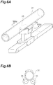
FIG. 6A is a diagram illustrating a support member used in the addition step S2 in the method for manufacturing an optical fiber preform. -
FIG. 6B is a partial cross-sectional view of the support member taken along line VI(b)-VI(b) illustrated inFIG. 6A . - When an alkali metal is added to a silica-based glass pipe for an optical fiber preform, the added alkali metal may cause transition of glass to a crystalline structure. In the method for manufacturing an optical fiber preform described in
Patent Literature 1, an outer surface of a silica-based glass pipe is heated by an oxyhydrogen burner to 2000°C or higher when an alkali metal is added to the silica-based glass pipe. This prevents devitrification of glass due to the crystalline structure. When the heating temperature for the silica-based glass pipe is high, the crystallization of glass can be suppressed but the silica-based glass pipe may be softened and become deformed or non-circular. It is therefore desired that while devitrification of the glass pipe for an optical fiber preform is suppressed, its deformation is also suppressed. - According to the present disclosure, while devitrification of the glass pipe used for an optical fiber preform is suppressed, the deformation of the glass pipe also can be suppressed.
- [Description of Embodiments of the Present Disclosure] Embodiments of the present disclosure will be described. A method for manufacturing an optical fiber preform according to an embodiment of the present disclosure is a method for manufacturing an optical fiber preform including a core part and a cladding part. The method includes: adding an alkali metal to an inner surface of a silica-based glass pipe; etching the inner surface of the silica-based glass pipe to which the alkali metal is added; making a glass rod by collapsing the silica-based glass pipe after the etching; and making an optical fiber preform using the glass rod. The silica-based glass pipe is heated in the adding such that the surface temperature of the silica-based glass pipe falls within a temperature range of 1500°C or higher to lower than 2000°C.
- In this method for manufacturing an optical fiber preform, when an alkali metal is added to the glass pipe, the silica-based glass pipe is heated by adjusting the surface temperature of the silica-based glass pipe within a temperature range of 1500°C or higher to lower than 2000°C. In this case, according to the study by the inventors of the present invention, it was confirmed that the glass pipe with the addition of an alkali metal is not devitrified and deformation of the glass pipe is suppressed. Thus, the surface temperature of the glass pipe is adjusted in a temperature range of 1500°C or higher to lower than 2000°C when an alkali metal is added, whereby devitrification of the glass pipe used for an optical fiber preform is suppressed and its deformation also can be suppressed, resulting in an optical fiber preform for manufacturing an optical fiber with low attenuation.
- In one aspect of the present embodiment, in the adding, the heating time per traverse with which the surface temperature of a predetermined area of the silica-based glass pipe falls within a temperature range of 1500°C or higher to lower than 2000°C may be 0.5 minute or longer and shorter than 40 minutes. In the adding, the heating time per traverse with which the surface temperature of the predetermined area of the silica-based glass pipe falls within a temperature range of 1500°C or higher to lower than 2000°C may be 1 minute or longer or may be shorter than 40 minutes. In this case, while devitrification of the glass pipe used for an optical fiber preform is suppressed, deformation or becoming non-circular of the glass pipe can be further suppressed. As used herein, "per traverse" refers to one traverse movement in one direction (single path).
- In one aspect of the present embodiment, in the adding, the silica-based glass pipe may be heated by a heating burner such that the surface temperature of the silica-based glass pipe falls within a temperature range of 1500°C or higher to lower than 2000°C, and the width that achieves a temperature zone of 1500°C or higher in the heating temperature profile of the heating burner may be kept to be not more than six times an outer diameter of the silica-based glass pipe. In this case, the silica-based glass pipe is heated more locally, so that the addition of an alkali metal to the glass pipe can be performed while deformation of the glass pipe due to the spread of the heating area is further suppressed.
- In one aspect of the present embodiment, in the adding, the silica-based glass pipe may be heated such that the surface temperature of the silica-based glass pipe falls within a temperature range of 1500°C or higher to lower than 1800°C.
- In one aspect of the present embodiment, in the adding, a space in which the silica-based glass pipe is held may be kept at a positive pressure, and the internal pressure in the space may be greater than 0 Pa and 20 Pa or less. In this case, deformation of the glass pipe by heating can be further suppressed.
- In one aspect of the present embodiment, the alkali metal added in the adding may be potassium, and the silica-based glass pipe may be repeatedly heated in the adding such that the ratio d2/d1 in the optical fiber preform is 1.5 or more and less than 3.0, where d1 is the diameter of an area in which the potassium concentration in the optical fiber preform is 50 [atomic ppm] or more, and d2 is the diameter of an area in which the potassium concentration in the optical fiber preform is 50 [atomic ppm] or less and the chlorine concentration is 1000 [atomic ppm] or less. In this case, crystallization of glass can be suppressed while the potassium-added area that can reduce attenuation of the optical fiber is increased.
- In another aspect, the present embodiment relates to a method for manufacturing an optical fiber. The method is a method for manufacturing an optical fiber using an optical fiber preform manufactured by the method for manufacturing an optical fiber preform according to any one or a combination of the aspects described above. The method for manufacturing an optical fiber further includes drawing the optical fiber preform to manufacture an optical fiber. In this case, since an optical fiber is manufactured using the glass rod made from the glass pipe in which devitrification and deformation are suppressed, an optical fiber with lower loss can be obtained.
- Specific examples of the method for manufacturing an optical fiber preform according to an embodiment of the present disclosure and the method for manufacturing an optical fiber using the optical fiber preform manufactured by this method will be described below with reference to the drawings. The present invention is not limited by such examples but shown by the claims, and it is intended that all modifications within the meaning and scope of equivalents to the claims are embraced therein. In the following description, the same elements in a description of the drawings are denoted by the same reference signs and an overlapping description will be omitted.
-
FIG. 1 is a cross-sectional view of an optical fiber preform manufactured by the method for manufacturing an optical fiber preform according to the present embodiment. Anoptical fiber preform 1 is formed of a silica-based glass and includes acore part 10 and acladding part 20 surrounding thecore part 10. The refractive index of thecore part 10 is higher than the refractive index of thecladding part 20. Thecore part 10 has afirst core part 11 and asecond core part 12 surrounding thefirst core part 11. Thecladding part 20 has afirst cladding part 21 surrounding thecore part 10 and asecond cladding part 22 surrounding thefirst cladding part 21. An alkali metal (for example, potassium) is added to thefirst core part 11 by the manufacturing method described later. -
FIG. 2 is a flowchart for explaining the method for manufacturing an optical fiber preform according to the present embodiment. In the method for manufacturing an optical fiber preform, as illustrated inFIG. 2 , a preparation step S1, an addition step S2, a diameter-reducing step S3, an etching step S4, a collapsing step S5, a first stretching and grinding step S6, a first rod-in collapse step S7, a second stretching and grinding step S8, a second rod-in collapse step S9, and an OVD step S10 are performed in order, to manufacture theoptical fiber preform 1 illustrated inFIG. 1 .FIG. 3 is a schematic diagram illustrating the process in the addition step S2 in the method for manufacturing an optical fiber preform. - In the preparation step S1, a silica-based glass pipe 31 (see
FIG. 3 ) into which an alkali metal element is to be diffused is first prepared. The silica-basedglass pipe 31 is a pipe that contains, for example, a predetermined amount of chlorine (Cl) and fluorine (F) and in which the concentrations of other dopants and impurities are kept to a predetermined amount or lower. The silica-basedglass pipe 31, for example, has an outer diameter of 35 mm and an inner diameter of 20 mm. - Subsequently, in the addition step S2, an alkali metal is added to the inner peripheral surface of the silica-based
glass pipe 31. For example, potassium (K), sodium (Na), rubidium (Rb), or cesium (Cs) can be used as the alkali metal added in the addition step. For example, when potassium bromide (KBr) is used asalkali metal material 33, as illustrated inFIG. 3 , potassium bromide is heated by anexternal heat source 32 to generate KBr vapor. Then, while KBr vapor is introduced together with the supplied carrier gas to the inner peripheral of the silica-basedglass pipe 31, the outer surface of the silica-basedglass pipe 31 is heated by aheating burner 34. In this heating process, theheating burner 34 is reciprocatively traversed multiple times (for example 10 turns) in the direction of the arrow in the drawing at a predetermined speed (for example 40 mm/min) to diffusively add the potassium metal into aninner surface 31a of the silica-basedglass pipe 31. In this case, for example, when KBr vapor is introduced to the inside of the silica-basedglass pipe 31 together with a carrier gas in which oxygen is introduced at a flow rate of 1 SLM (1 liter/min in terms of a normal condition), the maximum value of potassium concentration of the silica-basedglass pipe 31 to which the alkali metal is added can be set to 1000 [atomic ppm]. - In the heating process by the
heating burner 34 in the addition step in the present embodiment, heating is performed by adjusting theheating burner 34 such that the surface temperature of theglass pipe 31 is 1500°C or higher and lower than 2000°C, preferably, 1500°C or higher and 1800°C or lower. In other words, the heating process is performed such that the surface temperature of theglass pipe 31 does not exceed 2000°C. Theheating burner 34 has a preset prescribed temperature profile (seeFIG. 4 ) and is adjusted such that the width D in which the heating temperature is 1500°C or higher is not increased. In theheating burner 34, for example, the width D in the temperature profile is kept to be not more than six times the diameter of theglass pipe 31 heated. In the addition step, in addition to limiting the range of heating temperature, heating is performed by adjusting the traverse speed of theheating burner 34 such that the heating time (burner heating time) in each area of theglass pipe 31 by theheating burner 34 is within a predetermined range of 0.5 minute to 40 minutes, preferably, 1 minute or longer and shorter than 20 minutes. That is, the traverse speed is adjusted such that the heating time per traverse with which the surface temperature of a certain area of the silica-basedglass pipe 31 falls within a temperature range of 1500°C or higher to lower than 2000°C is 0.5 minute to 40 minutes, preferably, 1 minute or longer and shorter than 20 minutes. As used herein, "per traverse" refers to one traverse movement in one direction (single path). - In the addition step in the present embodiment, the heating temperature and the heating time by the
heating burner 34 are adjusted to a predetermined range, and then an alkali metal is diffusively added to theinner surface 31a of the silica-basedglass pipe 31. The adjustment of heating in this manner suppresses devitrification due to crystallization and thermal deformation of theglass pipe 31. For example, an oxyhydrogen burner can be used as theheating burner 34. The addition step may be performed in an environment in which a space in which the silica-basedglass pipe 31 is held is kept at a positive pressure and the internal pressure of the space is greater than 0 Pa and 20 Pa or less. - Subsequently, in the diameter-reducing step S3, after the supply of an alkali metal such as KBr vapor used in the addition step S2 is stopped, the diameter of the silica-based
glass pipe 31 to which the alkali metal is added is reduced. In doing so, while oxygen (for example, a flow rate of 0.5 SLM) is introduced to the inside of the silica-basedglass pipe 31, the silica-basedglass pipe 31 is heated by an external heat source such that the outer surface of the silica-basedglass pipe 31 attains 1600°C to 2100°C. Heating is performed by traversing theheating burner 34, for example, about 6 turns, and the diameter of the silica-basedglass pipe 31 to which the alkali metal is added is reduced until the inner diameter attains 5 mm. - Subsequently, in the etching step S4, the inner peripheral surface of the silica-based glass pipe having its diameter reduced is etched. In the etching step, while a gas mixture of SF6 (for example, a flow rate of 0.2 SLM) and chlorine (for example, a flow rate of 0.5 SLM) is introduced to the inside of the silica-based glass pipe having its diameter reduced, the silica-based glass pipe is heated by an external heat source to perform a vapor phase etching of the inner peripheral surface. In this process, the inner peripheral surface of the glass pipe is etched at a thickness of about 400 to 800 µm to remove the pipe inner surface containing a high concentration of impurities added together with the alkali metal in the addition step. The impurities are thus removed from the glass pipe.
- Subsequently, in the collapsing step S5, the silica-based glass pipe having its diameter reduced and having the etched inner peripheral surface is collapsed. In the collapsing step, the silica-based glass pipe is collapsed by reducing the absolute pressure inside the silica-based glass pipe to 97 kPa or lower while introducing a gas mixture of oxygen (for example, a flow rate of 0.1 SLM) and helium (for example, a flow rate of 1 SLM) to the inside of the silica-based glass pipe, and bringing the surface temperature of the silica-based glass pipe to 1600°C to 2100°C using an external heat source. This collapsing step results in a first glass rod (for example, an outer diameter of 25 mm) of a transparent silica-based glass containing an alkali metal. The alkali metal is diffusively added in the first glass rod.
- Subsequently, in the first stretching and grinding step S6, the first glass rod obtained by collapsing is stretched, for example, to a diameter of 20 mm, and the outer peripheral portion is further ground to a diameter of 12 mm, resulting in the
first core part 11. In doing so, as illustrated inFIG. 5 , when the diameter in which the K concentration is 50 [atomic ppm] or more is d1, and the outer diameter in which the K concentration is 50 [atomic ppm] or less and the Cl concentration is 1000 [atomic ppm] or less is d2, the ratio of d2/d1 in thefirst core part 11 can be set between 1.5 or more and less than 3.0. - Subsequently, in the first rod-in collapse step S7, the
second core part 12 is provided on the outside of thefirst core part 11, resulting in a second glass rod. In step S7, the second glass rod is manufactured by a rod-in collapse method in which thefirst core part 11 is inserted to the inside of a silica-based glass pipe (second core part 12) having an outer diameter of 55 mm and in which a predetermined amount of chlorine atoms is added, and they are heated to be integrated by an external heat source. - Subsequently, in the second stretching and grinding step S8, the second glass rod is stretched to a diameter of 24 mm, and the outer peripheral portion is further ground to a diameter of 17 mm. A combination of the
first core part 11 and thesecond core part 12 is thecore part 10. When the diameter of thecore part 10 is d3, the ratio of d3/d1 in thecore part 10 can be set to 4 to 8. - Subsequently, in the second rod-in collapse step S9, the
first cladding part 21 is provided on thecore part 10. In this step, a rod-in collapse method is used in which thecore part 10 is inserted to the inside of a silica-based glass pipe (corresponding to the first cladding part 21) in which a predetermined amount of fluoride is added, and they are heated to be integrated by an external heat source. The relative ratio refractive index difference between thesecond core part 12 and thefirst cladding part 21 is, for example, at most about 0.34%. As a result of the synthesis by this rod-in collapse method, the moisture in thecore part 10 and the neighboringfirst cladding part 21 can be suppressed to be sufficiently low. - Subsequently, in the OVD step S10, the glass rod formed by integrating the
core part 10 and thefirst cladding part 21 is stretched to a predetermined diameter, and thereafter thesecond cladding part 22 containing fluoride is synthesized on the outside of the glass rod by the OVD method to manufacture theoptical fiber preform 1. In the resultantoptical fiber preform 1, for example, the outer diameter of thefirst cladding part 21 is 36 mm, and the outer diameter of thesecond cladding part 22 is 140 mm. The relative ratio refractive index difference between thesecond core part 12 and thesecond cladding part 22 is at most about 0.32%. The concentration of OH group on the outside of thefirst cladding part 21 can be measured using infrared absorption spectroscopy and is about 400 [mol ppm]. - In the subsequent drawing step, the
optical fiber preform 1 manufactured by the manufacturing method as described above is drawn to obtain an optical fiber. The drawing speed is, for example, 2300 m/min, and the drawing tension can be 0.5 N. As described above, an optical fiber with low attenuation by addition of an alkali metal, and an optical fiber preform for the optical fiber can be manufactured. - The degree of crystallization (devitrification) and deformation (becoming non-circular) of the optical fiber preform manufactured by the manufacturing method described above will now be described. As described above, in the method for manufacturing an optical fiber preform according to the present embodiment, in the addition step S2 of adding an alkali metal, the heating temperature in adding an alkali metal such as potassium to the silica-based
glass pipe 31 is adjusted to fall within a range of 1500°C or higher to lower than 2000°C. That is, the heating process is adjusted such that the surface temperature of the silica-basedglass pipe 31 quickly reaches 1500°C and does not exceed 2000°C. In this way, the glass temperature of the surface of the silica-based glass pipe is adjusted not to low temperatures (1200°C or higher to lower than 1500°C) but to high temperatures (1500°C or higher), so that formation or growth of crystalline nuclei of silica (SiO2) forming the glass pipe is not promoted, thereby preventing the crystalline structure from being kept. With such adjustment, even when glass is easily crystallized due to the alkali metal added to reduce the attenuation of the optical fiber, devitrification of the silica-based glass pipe used for manufacturing an optical fiber preform can be suppressed. - Diffusion and penetration of an alkali metal in the glass proceed by keeping a high surface temperature of the glass pipe to which the alkali metal is added. However, it has been found that when the glass heating temperature is further higher (2000°C or higher), the fiber preform itself is deformed or becomes non-circular due to heat. Then, in the present embodiment, the upper limit of the heating temperature in the addition step is defined to lower than 2000°C. This can suppress heating of the glass pipe to a certain degree when an alkali metal is added to the silica-based glass pipe and can also suppress deformation or becoming non-circular of the optical fiber preform. The glass heating temperature is adjusted to lower than 2000°C as in the method for manufacturing an optical fiber preform according to the present embodiment, whereby deformation or becoming non-circular of the optical fiber preform can be suppressed, and an optical fiber manufactured using such an optical fiber preform achieves low attenuation.
- In the method for manufacturing an optical fiber preform according to the present embodiment, in the addition step, the heating time per traverse with which the surface temperature of a predetermined area of the silica-based
glass pipe 31 falls within a temperature range of 1500°C or higher to lower than 2000°C can be set to 1 minute or longer to shorter than 20 minutes. In this case, while devitrification of the glass pipe for an optical fiber preform is suppressed, deformation or becoming non-circular of the glass pipe can be further suppressed. - In the method for manufacturing an optical fiber preform according to the present embodiment, in the addition step, the silica-based
glass pipe 31 may be heated by theheating burner 34 such that the surface temperature of the silica-basedglass pipe 31 falls within a temperature range of 1500°C or higher to lower than 2000°C, and the width D that achieves a temperature zone of 1500°C or higher in the heating temperature profile (seeFIG. 4 ) of theheating burner 34 may be kept to be not more than six times the diameter of the silica-basedglass pipe 31. In this case, the silica-basedglass pipe 31 is heated more locally, so that the addition of an alkali metal to the glass pipe can be performed while deformation of the glass pipe due to the spread of heating is further suppressed. - In the method for manufacturing an optical fiber preform according to the present embodiment, in the addition step, an space in which the silica-based
glass pipe 31 is held may be kept at a positive pressure, and the internal pressure of the space may be greater than 0 Pa and 20 Pa or less. In such a pressure state, the deformation of the glass pipe by heating can be further suppressed. - An optical fiber preform was manufactured based on the manufacturing method described above, and the presence/absence of devitrification of the glass pipe and the presence/absence of deformation of the glass pipe were evaluated. The prepared silica-based glass pipe had an outer diameter of 35 mm and an inner diameter of 20 mm. Potassium bromide (KBr) as an alkali metal for adding to the glass pipe was heated by an external heat source to 840°C to generate KBr vapor. Then, while KBr vapor was introduced into the silica-based
glass pipe 31 together with a carrier gas in which oxygen was introduced at a flow rate of 1 SLM, heating was performed from the outside by an oxyhydrogen burner (heating burner 34) traversing such that the surface of the silica-basedglass pipe 31 reached a range of 1500°C or higher to 1800°C or lower. The heating time by the oxyhydrogen burner (burner heating time) is a value obtained by dividing the burner heating range by a traverse speed and means a heating time during which a certain point (area) in the glass pipe is heated to 1500°C or higher. The temperature profile (seeFIG. 4 ) of the burner was set such that the heating range (the width D illustrated inFIG. 4 ) by the oxyhydrogen burner was 165 mm (the range of temperatures of 1500°C or higher). The number of turns (the number of reciprocations) of traverse by the oxyhydrogen burner is set to 10. - Then, as illustrated below, the presence/absence of devitrification and the presence/absence of deformation of the glass pipe were evaluated by adjusting the traverse speed of the oxyhydrogen burner to change the burner heating time stepwise from 0.5 minute to 40 minutes. The evaluation result is illustrated in Table 1 below.
[Table 1] Burner heating time (minute) Presence/absence of devitrification Presence/absence of deformation 0.5 B A 1 A A 2 A A 4 A A 8 A A 12 A A 16 A A 20 A B 40 A B - In the presence/absence of devitrification in Table 1, "A" indicates a state in which no devitrification occurs and "B" indicates a state in which devitrification partially occurs. "A" in the presence/absence of deformation indicates a state in which the deformation of the glass pipe (an effective length of 100 mm) is 2 mm or less, and "B" in the presence/absence of deformation indicates a state in which the deformation of the glass pipe is 2 mm or more and 5 mm or less.
- As is clear from Example above, it was confirmed that the surface temperature of the glass pipe is set to 1500°C or higher to lower than 2000°C when an alkali metal is added to the glass pipe, whereby devitrification due to crystallization of the glass pipe can be suppressed and deformation due to heating of the glass pipe can be suppressed. In addition, the time during which the surface temperature of the glass pipe is set to 1500°C or higher to lower than 2000°C is set to 0.5 minute or longer and 40 minutes or shorter, more preferably, 1 minute or longer and shorter than 20 minutes when an alkali metal is added to the glass pipe, whereby thermal deformation of the optical fiber preform can be further suppressed.
- A method for manufacturing an optical fiber preform according to the present embodiment and a method for manufacturing an optical fiber using an optical fiber preform manufactured by this method have been described above. However, the present invention is not limited thereto and a variety of modifications can be applied. For example, in the addition step S2 in the above method for manufacturing an optical fiber preform, the
glass pipe 31 is heated by theheating burner 34 with only both ends thereof supported. However, in order to further suppress deformation of theglass pipe 31, for example, as illustrated inFIG. 6A and FIG. 6B , tworotatable support rollers 35 having an axis parallel to the axis of theglass pipe 31 may be provided under theglass pipe 31 to support theglass pipe 31. In this case, deformation of theglass pipe 31 by heat can be further suppressed. In this case, therotatable support rollers 35 may be disposed immediately outside of the range in which the heating burner is traversed, or therotatable support rollers 35 may be disposed at a certain distance from the heating burner, and therotatable support rollers 35 and the heating burner may be traversed simultaneously. - 1 ... optical fiber preform, 10 ... core part, 11 ... first core part, 12 ... second core part, 20 ... cladding part, 21 ... first cladding part, 22 ... second cladding part, 31 ... glass pipe, 32 ... external heat source, 33 ... alkali metal material, 34 ... heating burner, 35 ... rotatable support roller, D ... width.
Claims (9)
- A method for manufacturing an optical fiber preform including a core part and a cladding part, comprising:adding an alkali metal to an inner surface of a silica-based glass pipe;etching the inner surface of the silica-based glass pipe to which the alkali metal is added;making a glass rod by collapsing the silica-based glass pipe after the etching; andmaking an optical fiber preform using the glass rod,wherein the silica-based glass pipe is heated in the adding such that a surface temperature of the silica-based glass pipe falls within a temperature range of 1500°C or higher to lower than 2000°C.
- The method for manufacturing an optical fiber preform according to claim 1, wherein in the adding, the heating time per traverse with which a surface temperature of a predetermined area of the silica-based glass pipe falls within a temperature range of 1500°C or higher to lower than 2000°C is 0.5 minute or longer and shorter than 40 minutes.
- The method for manufacturing an optical fiber preform according to claim 2, wherein in the adding, the heating time per traverse with which the surface temperature of the predetermined area of the silica-based glass pipe falls within a temperature range of 1500°C or higher to lower than 2000°C is 1 minute or longer.
- The method for manufacturing an optical fiber preform according to claim 2 or 3, wherein in the adding, the heating time per traverse with which the surface temperature of the predetermined area of the silica-based glass pipe falls within a temperature range of 1500°C or higher to lower than 2000°C is shorter than 20 minutes.
- The method for manufacturing an optical fiber preform according to any one of claims 1 to 4, wherein in the adding,
the silica-based glass pipe is heated by a heating burner such that the surface temperature of the silica-based glass pipe falls within a temperature range of 1500°C or higher to lower than 2000°C, and
the width that achieves a temperature zone of 1500°C or higher in the heating temperature profile of the heating burner is kept to be not more than six times a diameter of the silica-based glass pipe. - The method for manufacturing an optical fiber preform according to any one of claims 1 to 5, wherein in the adding, the silica-based glass pipe is heated such that the surface temperature of the silica-based glass pipe falls within a temperature range of 1500°C or higher to lower than 1800°C.
- The method for manufacturing an optical fiber preform according to any one of claims 1 to 5, wherein in the adding,
a space in which the silica-based glass pipe is held is kept at a positive pressure, and
the internal pressure in the space is greater than 0 Pa and 20 Pa or less. - The method for manufacturing an optical fiber preform according to any one of claims 1 to 7,
wherein the alkali metal added in the adding is potassium, and wherein the silica-based glass pipe is repeatedly heated in the adding such that the ratio d2/d1 in the optical fiber preform is 1.5 or more and less than 3.0 where d1 is the diameter of an area in which the potassium concentration in the optical fiber preform is 50 [atomic ppm] or more, and d2 is the diameter of an area in which the potassium concentration in the optical fiber preform is 50 [atomic ppm] or less and the chlorine concentration is 1000 [atomic ppm] or less. - A method for manufacturing an optical fiber using an optical fiber preform manufactured by the method for manufacturing an optical fiber preform according to any one of claims 1 to 8, the method for manufacturing an optical fiber further comprising drawing the optical fiber preform to manufacture an optical fiber.
Applications Claiming Priority (2)
| Application Number | Priority Date | Filing Date | Title |
|---|---|---|---|
| JP2017167406 | 2017-08-31 | ||
| PCT/JP2018/031770 WO2019044833A1 (en) | 2017-08-31 | 2018-08-28 | Method for manufacturing optical fiber parent material, and method for manufacturing optical fiber |
Publications (2)
| Publication Number | Publication Date |
|---|---|
| EP3677556A1 true EP3677556A1 (en) | 2020-07-08 |
| EP3677556A4 EP3677556A4 (en) | 2021-05-26 |
Family
ID=65525466
Family Applications (1)
| Application Number | Title | Priority Date | Filing Date |
|---|---|---|---|
| EP18850562.2A Pending EP3677556A4 (en) | 2017-08-31 | 2018-08-28 | Method for manufacturing optical fiber parent material, and method for manufacturing optical fiber |
Country Status (5)
| Country | Link |
|---|---|
| US (1) | US11667559B2 (en) |
| EP (1) | EP3677556A4 (en) |
| JP (1) | JP7276134B2 (en) |
| CN (1) | CN111094198A (en) |
| WO (1) | WO2019044833A1 (en) |
Families Citing this family (3)
| Publication number | Priority date | Publication date | Assignee | Title |
|---|---|---|---|---|
| CN113848608B (en) * | 2020-06-28 | 2023-08-08 | 中天科技精密材料有限公司 | Single-mode optical fiber and preparation method thereof |
| JPWO2022004415A1 (en) * | 2020-07-03 | 2022-01-06 | ||
| WO2024048356A1 (en) * | 2022-08-29 | 2024-03-07 | 住友電気工業株式会社 | Method for producing optical fiber preform, and optical fiber preform |
Family Cites Families (20)
| Publication number | Priority date | Publication date | Assignee | Title |
|---|---|---|---|---|
| GB1555562A (en) * | 1977-04-04 | 1979-11-14 | Gen Electric Co Ltd | Manufacture of optical fibre preforms and optical optical fibre wavequides |
| JP3258478B2 (en) | 1993-12-28 | 2002-02-18 | 信越石英株式会社 | High viscosity synthetic quartz glass tube for thermal CVD method and quartz glass preform for optical fiber using the same |
| JP3774159B2 (en) | 2001-04-03 | 2006-05-10 | 株式会社フジクラ | Dispersion compensation optical fiber connection structure |
| US20040057692A1 (en) * | 2002-08-28 | 2004-03-25 | Ball Laura J. | Low loss optical fiber and method for making same |
| JP2004295010A (en) | 2003-03-28 | 2004-10-21 | Sumitomo Electric Ind Ltd | Optical fiber |
| KR101066281B1 (en) * | 2003-08-29 | 2011-09-20 | 코닝 인코포레이티드 | Optical Fiber Containing an Alkali Metal Oxide and Methods and Apparatus for Manufacturing Same |
| JP4552599B2 (en) | 2004-10-29 | 2010-09-29 | 住友電気工業株式会社 | Optical fiber preform manufacturing method |
| US7536076B2 (en) | 2006-06-21 | 2009-05-19 | Corning Incorporated | Optical fiber containing alkali metal oxide |
| US20080050086A1 (en) * | 2006-08-24 | 2008-02-28 | Scott Robertson Bickham | Optical fiber containing alkali metal oxide |
| JP5656469B2 (en) * | 2010-06-23 | 2015-01-21 | 株式会社フジクラ | Glass base material manufacturing apparatus and manufacturing method |
| US9139466B2 (en) * | 2011-01-20 | 2015-09-22 | Sumitomo Electric Industries, Ltd. | Optical fiber preform, optical fiber, and method of manufacturing optical fiber preform |
| JP5545236B2 (en) * | 2011-02-03 | 2014-07-09 | 住友電気工業株式会社 | Optical fiber preform manufacturing method |
| WO2013111470A1 (en) | 2012-01-25 | 2013-08-01 | 住友電気工業株式会社 | Method for producing optical fiber preform, optical fiber preform, and optical fiber |
| WO2013118389A1 (en) | 2012-02-09 | 2013-08-15 | 住友電気工業株式会社 | Optical fiber preform manufacturing method, optical fiber preform, and optical fiber |
| US9411095B2 (en) * | 2013-02-04 | 2016-08-09 | Sumitomo Electric Industries, Ltd. | Optical-fiber preform and method for manufacturing optical-fiber preform |
| JP2014214079A (en) | 2013-04-30 | 2014-11-17 | 住友電気工業株式会社 | Optical fiber preform |
| JP2015105199A (en) | 2013-11-29 | 2015-06-08 | 住友電気工業株式会社 | Optical fiber and optical fiber preform |
| JP2015137201A (en) * | 2014-01-22 | 2015-07-30 | 日立金属株式会社 | Optical fiber parent material producing method, and optical fiber parent material |
| JP5995923B2 (en) | 2014-08-06 | 2016-09-21 | 古河電気工業株式会社 | Optical fiber preform and optical fiber manufacturing method |
| JP2017167406A (en) | 2016-03-17 | 2017-09-21 | シャープ株式会社 | Liquid crystal display device and television apparatus |
-
2018
- 2018-08-28 JP JP2019539532A patent/JP7276134B2/en active Active
- 2018-08-28 CN CN201880054878.XA patent/CN111094198A/en active Pending
- 2018-08-28 US US16/641,778 patent/US11667559B2/en active Active
- 2018-08-28 EP EP18850562.2A patent/EP3677556A4/en active Pending
- 2018-08-28 WO PCT/JP2018/031770 patent/WO2019044833A1/en unknown
Also Published As
| Publication number | Publication date |
|---|---|
| EP3677556A4 (en) | 2021-05-26 |
| CN111094198A (en) | 2020-05-01 |
| US11667559B2 (en) | 2023-06-06 |
| JP7276134B2 (en) | 2023-05-18 |
| JPWO2019044833A1 (en) | 2020-10-15 |
| WO2019044833A1 (en) | 2019-03-07 |
| US20200247710A1 (en) | 2020-08-06 |
Similar Documents
| Publication | Publication Date | Title |
|---|---|---|
| EP2479150B1 (en) | Optical fiber preform, optical fiber, and method of manufacturing optical fiber preform | |
| EP2511741B1 (en) | Optical fibre with alkali doped core and optical fiber preform | |
| EP2484643B1 (en) | Method for producing a glass optical fiber preform | |
| EP2484644B1 (en) | Method for producing a glass optical fiber preform | |
| US11667559B2 (en) | Method for manufacturing optical fiber parent material, and method for manufacturing optical fiber | |
| KR20050031110A (en) | Low loss optical fiber and method for making same | |
| US10550030B2 (en) | Optical fiber | |
| EP2125645B1 (en) | Reduction of optical fiber cane/preform deformation during consolidation | |
| US10155687B2 (en) | Optical fiber preform | |
| EP3421435A1 (en) | Optical fiber | |
| US9575245B2 (en) | Optical fiber | |
| US10723650B2 (en) | Optical fiber preform | |
| EP3173388B1 (en) | Method of manufacturing optical fiber preform | |
| CA2948666C (en) | Polarization controlling optical fiber preform and preform fabrication methods | |
| US20230202904A1 (en) | Method for producing optical fiber base material, and optical fiber base material | |
| US20230322605A1 (en) | Production method for optical fiber base material, and optical fiber base material | |
| US10947149B2 (en) | Halogen-doped silica for optical fiber preforms | |
| WO2018211880A1 (en) | Method for producing optical fiber base material, and optical fiber base material |
Legal Events
| Date | Code | Title | Description |
|---|---|---|---|
| STAA | Information on the status of an ep patent application or granted ep patent |
Free format text: STATUS: THE INTERNATIONAL PUBLICATION HAS BEEN MADE |
|
| PUAI | Public reference made under article 153(3) epc to a published international application that has entered the european phase |
Free format text: ORIGINAL CODE: 0009012 |
|
| STAA | Information on the status of an ep patent application or granted ep patent |
Free format text: STATUS: REQUEST FOR EXAMINATION WAS MADE |
|
| 17P | Request for examination filed |
Effective date: 20200312 |
|
| AK | Designated contracting states |
Kind code of ref document: A1 Designated state(s): AL AT BE BG CH CY CZ DE DK EE ES FI FR GB GR HR HU IE IS IT LI LT LU LV MC MK MT NL NO PL PT RO RS SE SI SK SM TR |
|
| AX | Request for extension of the european patent |
Extension state: BA ME |
|
| DAV | Request for validation of the european patent (deleted) | ||
| DAX | Request for extension of the european patent (deleted) | ||
| A4 | Supplementary search report drawn up and despatched |
Effective date: 20210428 |
|
| RIC1 | Information provided on ipc code assigned before grant |
Ipc: C03B 37/018 20060101AFI20210421BHEP Ipc: C03B 37/012 20060101ALI20210421BHEP Ipc: C03B 37/027 20060101ALI20210421BHEP Ipc: G02B 6/02 20060101ALI20210421BHEP Ipc: C03B 37/014 20060101ALN20210421BHEP |
|
| STAA | Information on the status of an ep patent application or granted ep patent |
Free format text: STATUS: EXAMINATION IS IN PROGRESS |
|
| 17Q | First examination report despatched |
Effective date: 20240119 |