EP3677497A1 - Liquefied gas carrying vessel - Google Patents
Liquefied gas carrying vessel Download PDFInfo
- Publication number
- EP3677497A1 EP3677497A1 EP18851538.1A EP18851538A EP3677497A1 EP 3677497 A1 EP3677497 A1 EP 3677497A1 EP 18851538 A EP18851538 A EP 18851538A EP 3677497 A1 EP3677497 A1 EP 3677497A1
- Authority
- EP
- European Patent Office
- Prior art keywords
- tank
- tank cover
- liquefied gas
- opening
- amount
- Prior art date
- Legal status (The legal status is an assumption and is not a legal conclusion. Google has not performed a legal analysis and makes no representation as to the accuracy of the status listed.)
- Granted
Links
Images


Classifications
-
- F—MECHANICAL ENGINEERING; LIGHTING; HEATING; WEAPONS; BLASTING
- F17—STORING OR DISTRIBUTING GASES OR LIQUIDS
- F17C—VESSELS FOR CONTAINING OR STORING COMPRESSED, LIQUEFIED OR SOLIDIFIED GASES; FIXED-CAPACITY GAS-HOLDERS; FILLING VESSELS WITH, OR DISCHARGING FROM VESSELS, COMPRESSED, LIQUEFIED, OR SOLIDIFIED GASES
- F17C13/00—Details of vessels or of the filling or discharging of vessels
- F17C13/001—Thermal insulation specially adapted for cryogenic vessels
-
- B—PERFORMING OPERATIONS; TRANSPORTING
- B63—SHIPS OR OTHER WATERBORNE VESSELS; RELATED EQUIPMENT
- B63B—SHIPS OR OTHER WATERBORNE VESSELS; EQUIPMENT FOR SHIPPING
- B63B25/00—Load-accommodating arrangements, e.g. stowing, trimming; Vessels characterised thereby
- B63B25/02—Load-accommodating arrangements, e.g. stowing, trimming; Vessels characterised thereby for bulk goods
- B63B25/08—Load-accommodating arrangements, e.g. stowing, trimming; Vessels characterised thereby for bulk goods fluid
- B63B25/12—Load-accommodating arrangements, e.g. stowing, trimming; Vessels characterised thereby for bulk goods fluid closed
- B63B25/16—Load-accommodating arrangements, e.g. stowing, trimming; Vessels characterised thereby for bulk goods fluid closed heat-insulated
-
- B—PERFORMING OPERATIONS; TRANSPORTING
- B05—SPRAYING OR ATOMISING IN GENERAL; APPLYING FLUENT MATERIALS TO SURFACES, IN GENERAL
- B05B—SPRAYING APPARATUS; ATOMISING APPARATUS; NOZZLES
- B05B1/00—Nozzles, spray heads or other outlets, with or without auxiliary devices such as valves, heating means
- B05B1/14—Nozzles, spray heads or other outlets, with or without auxiliary devices such as valves, heating means with multiple outlet openings; with strainers in or outside the outlet opening
- B05B1/16—Nozzles, spray heads or other outlets, with or without auxiliary devices such as valves, heating means with multiple outlet openings; with strainers in or outside the outlet opening having selectively- effective outlets
-
- B—PERFORMING OPERATIONS; TRANSPORTING
- B05—SPRAYING OR ATOMISING IN GENERAL; APPLYING FLUENT MATERIALS TO SURFACES, IN GENERAL
- B05B—SPRAYING APPARATUS; ATOMISING APPARATUS; NOZZLES
- B05B12/00—Arrangements for controlling delivery; Arrangements for controlling the spray area
- B05B12/08—Arrangements for controlling delivery; Arrangements for controlling the spray area responsive to condition of liquid or other fluent material to be discharged, of ambient medium or of target ; responsive to condition of spray devices or of supply means, e.g. pipes, pumps or their drive means
- B05B12/12—Arrangements for controlling delivery; Arrangements for controlling the spray area responsive to condition of liquid or other fluent material to be discharged, of ambient medium or of target ; responsive to condition of spray devices or of supply means, e.g. pipes, pumps or their drive means responsive to conditions of ambient medium or target, e.g. humidity, temperature position or movement of the target relative to the spray apparatus
-
- B—PERFORMING OPERATIONS; TRANSPORTING
- B63—SHIPS OR OTHER WATERBORNE VESSELS; RELATED EQUIPMENT
- B63J—AUXILIARIES ON VESSELS
- B63J2/00—Arrangements of ventilation, heating, cooling, or air-conditioning
- B63J2/12—Heating; Cooling
-
- F—MECHANICAL ENGINEERING; LIGHTING; HEATING; WEAPONS; BLASTING
- F17—STORING OR DISTRIBUTING GASES OR LIQUIDS
- F17C—VESSELS FOR CONTAINING OR STORING COMPRESSED, LIQUEFIED OR SOLIDIFIED GASES; FIXED-CAPACITY GAS-HOLDERS; FILLING VESSELS WITH, OR DISCHARGING FROM VESSELS, COMPRESSED, LIQUEFIED, OR SOLIDIFIED GASES
- F17C13/00—Details of vessels or of the filling or discharging of vessels
- F17C13/004—Details of vessels or of the filling or discharging of vessels for large storage vessels not under pressure
-
- F—MECHANICAL ENGINEERING; LIGHTING; HEATING; WEAPONS; BLASTING
- F17—STORING OR DISTRIBUTING GASES OR LIQUIDS
- F17C—VESSELS FOR CONTAINING OR STORING COMPRESSED, LIQUEFIED OR SOLIDIFIED GASES; FIXED-CAPACITY GAS-HOLDERS; FILLING VESSELS WITH, OR DISCHARGING FROM VESSELS, COMPRESSED, LIQUEFIED, OR SOLIDIFIED GASES
- F17C3/00—Vessels not under pressure
- F17C3/02—Vessels not under pressure with provision for thermal insulation
- F17C3/025—Bulk storage in barges or on ships
-
- F—MECHANICAL ENGINEERING; LIGHTING; HEATING; WEAPONS; BLASTING
- F17—STORING OR DISTRIBUTING GASES OR LIQUIDS
- F17C—VESSELS FOR CONTAINING OR STORING COMPRESSED, LIQUEFIED OR SOLIDIFIED GASES; FIXED-CAPACITY GAS-HOLDERS; FILLING VESSELS WITH, OR DISCHARGING FROM VESSELS, COMPRESSED, LIQUEFIED, OR SOLIDIFIED GASES
- F17C3/00—Vessels not under pressure
- F17C3/02—Vessels not under pressure with provision for thermal insulation
- F17C3/04—Vessels not under pressure with provision for thermal insulation by insulating layers
-
- F—MECHANICAL ENGINEERING; LIGHTING; HEATING; WEAPONS; BLASTING
- F17—STORING OR DISTRIBUTING GASES OR LIQUIDS
- F17C—VESSELS FOR CONTAINING OR STORING COMPRESSED, LIQUEFIED OR SOLIDIFIED GASES; FIXED-CAPACITY GAS-HOLDERS; FILLING VESSELS WITH, OR DISCHARGING FROM VESSELS, COMPRESSED, LIQUEFIED, OR SOLIDIFIED GASES
- F17C2201/00—Vessel construction, in particular geometry, arrangement or size
- F17C2201/01—Shape
- F17C2201/0104—Shape cylindrical
-
- F—MECHANICAL ENGINEERING; LIGHTING; HEATING; WEAPONS; BLASTING
- F17—STORING OR DISTRIBUTING GASES OR LIQUIDS
- F17C—VESSELS FOR CONTAINING OR STORING COMPRESSED, LIQUEFIED OR SOLIDIFIED GASES; FIXED-CAPACITY GAS-HOLDERS; FILLING VESSELS WITH, OR DISCHARGING FROM VESSELS, COMPRESSED, LIQUEFIED, OR SOLIDIFIED GASES
- F17C2201/00—Vessel construction, in particular geometry, arrangement or size
- F17C2201/01—Shape
- F17C2201/0128—Shape spherical or elliptical
-
- F—MECHANICAL ENGINEERING; LIGHTING; HEATING; WEAPONS; BLASTING
- F17—STORING OR DISTRIBUTING GASES OR LIQUIDS
- F17C—VESSELS FOR CONTAINING OR STORING COMPRESSED, LIQUEFIED OR SOLIDIFIED GASES; FIXED-CAPACITY GAS-HOLDERS; FILLING VESSELS WITH, OR DISCHARGING FROM VESSELS, COMPRESSED, LIQUEFIED, OR SOLIDIFIED GASES
- F17C2201/00—Vessel construction, in particular geometry, arrangement or size
- F17C2201/03—Orientation
- F17C2201/032—Orientation with substantially vertical main axis
-
- F—MECHANICAL ENGINEERING; LIGHTING; HEATING; WEAPONS; BLASTING
- F17—STORING OR DISTRIBUTING GASES OR LIQUIDS
- F17C—VESSELS FOR CONTAINING OR STORING COMPRESSED, LIQUEFIED OR SOLIDIFIED GASES; FIXED-CAPACITY GAS-HOLDERS; FILLING VESSELS WITH, OR DISCHARGING FROM VESSELS, COMPRESSED, LIQUEFIED, OR SOLIDIFIED GASES
- F17C2201/00—Vessel construction, in particular geometry, arrangement or size
- F17C2201/05—Size
- F17C2201/052—Size large (>1000 m3)
-
- F—MECHANICAL ENGINEERING; LIGHTING; HEATING; WEAPONS; BLASTING
- F17—STORING OR DISTRIBUTING GASES OR LIQUIDS
- F17C—VESSELS FOR CONTAINING OR STORING COMPRESSED, LIQUEFIED OR SOLIDIFIED GASES; FIXED-CAPACITY GAS-HOLDERS; FILLING VESSELS WITH, OR DISCHARGING FROM VESSELS, COMPRESSED, LIQUEFIED, OR SOLIDIFIED GASES
- F17C2205/00—Vessel construction, in particular mounting arrangements, attachments or identifications means
- F17C2205/01—Mounting arrangements
- F17C2205/0103—Exterior arrangements
- F17C2205/0107—Frames
-
- F—MECHANICAL ENGINEERING; LIGHTING; HEATING; WEAPONS; BLASTING
- F17—STORING OR DISTRIBUTING GASES OR LIQUIDS
- F17C—VESSELS FOR CONTAINING OR STORING COMPRESSED, LIQUEFIED OR SOLIDIFIED GASES; FIXED-CAPACITY GAS-HOLDERS; FILLING VESSELS WITH, OR DISCHARGING FROM VESSELS, COMPRESSED, LIQUEFIED, OR SOLIDIFIED GASES
- F17C2205/00—Vessel construction, in particular mounting arrangements, attachments or identifications means
- F17C2205/01—Mounting arrangements
- F17C2205/0123—Mounting arrangements characterised by number of vessels
- F17C2205/013—Two or more vessels
-
- F—MECHANICAL ENGINEERING; LIGHTING; HEATING; WEAPONS; BLASTING
- F17—STORING OR DISTRIBUTING GASES OR LIQUIDS
- F17C—VESSELS FOR CONTAINING OR STORING COMPRESSED, LIQUEFIED OR SOLIDIFIED GASES; FIXED-CAPACITY GAS-HOLDERS; FILLING VESSELS WITH, OR DISCHARGING FROM VESSELS, COMPRESSED, LIQUEFIED, OR SOLIDIFIED GASES
- F17C2221/00—Handled fluid, in particular type of fluid
- F17C2221/01—Pure fluids
- F17C2221/012—Hydrogen
-
- F—MECHANICAL ENGINEERING; LIGHTING; HEATING; WEAPONS; BLASTING
- F17—STORING OR DISTRIBUTING GASES OR LIQUIDS
- F17C—VESSELS FOR CONTAINING OR STORING COMPRESSED, LIQUEFIED OR SOLIDIFIED GASES; FIXED-CAPACITY GAS-HOLDERS; FILLING VESSELS WITH, OR DISCHARGING FROM VESSELS, COMPRESSED, LIQUEFIED, OR SOLIDIFIED GASES
- F17C2221/00—Handled fluid, in particular type of fluid
- F17C2221/03—Mixtures
- F17C2221/032—Hydrocarbons
-
- F—MECHANICAL ENGINEERING; LIGHTING; HEATING; WEAPONS; BLASTING
- F17—STORING OR DISTRIBUTING GASES OR LIQUIDS
- F17C—VESSELS FOR CONTAINING OR STORING COMPRESSED, LIQUEFIED OR SOLIDIFIED GASES; FIXED-CAPACITY GAS-HOLDERS; FILLING VESSELS WITH, OR DISCHARGING FROM VESSELS, COMPRESSED, LIQUEFIED, OR SOLIDIFIED GASES
- F17C2221/00—Handled fluid, in particular type of fluid
- F17C2221/03—Mixtures
- F17C2221/032—Hydrocarbons
- F17C2221/033—Methane, e.g. natural gas, CNG, LNG, GNL, GNC, PLNG
-
- F—MECHANICAL ENGINEERING; LIGHTING; HEATING; WEAPONS; BLASTING
- F17—STORING OR DISTRIBUTING GASES OR LIQUIDS
- F17C—VESSELS FOR CONTAINING OR STORING COMPRESSED, LIQUEFIED OR SOLIDIFIED GASES; FIXED-CAPACITY GAS-HOLDERS; FILLING VESSELS WITH, OR DISCHARGING FROM VESSELS, COMPRESSED, LIQUEFIED, OR SOLIDIFIED GASES
- F17C2221/00—Handled fluid, in particular type of fluid
- F17C2221/03—Mixtures
- F17C2221/032—Hydrocarbons
- F17C2221/035—Propane butane, e.g. LPG, GPL
-
- F—MECHANICAL ENGINEERING; LIGHTING; HEATING; WEAPONS; BLASTING
- F17—STORING OR DISTRIBUTING GASES OR LIQUIDS
- F17C—VESSELS FOR CONTAINING OR STORING COMPRESSED, LIQUEFIED OR SOLIDIFIED GASES; FIXED-CAPACITY GAS-HOLDERS; FILLING VESSELS WITH, OR DISCHARGING FROM VESSELS, COMPRESSED, LIQUEFIED, OR SOLIDIFIED GASES
- F17C2223/00—Handled fluid before transfer, i.e. state of fluid when stored in the vessel or before transfer from the vessel
- F17C2223/01—Handled fluid before transfer, i.e. state of fluid when stored in the vessel or before transfer from the vessel characterised by the phase
- F17C2223/0146—Two-phase
- F17C2223/0153—Liquefied gas, e.g. LPG, GPL
-
- F—MECHANICAL ENGINEERING; LIGHTING; HEATING; WEAPONS; BLASTING
- F17—STORING OR DISTRIBUTING GASES OR LIQUIDS
- F17C—VESSELS FOR CONTAINING OR STORING COMPRESSED, LIQUEFIED OR SOLIDIFIED GASES; FIXED-CAPACITY GAS-HOLDERS; FILLING VESSELS WITH, OR DISCHARGING FROM VESSELS, COMPRESSED, LIQUEFIED, OR SOLIDIFIED GASES
- F17C2223/00—Handled fluid before transfer, i.e. state of fluid when stored in the vessel or before transfer from the vessel
- F17C2223/01—Handled fluid before transfer, i.e. state of fluid when stored in the vessel or before transfer from the vessel characterised by the phase
- F17C2223/0146—Two-phase
- F17C2223/0153—Liquefied gas, e.g. LPG, GPL
- F17C2223/0161—Liquefied gas, e.g. LPG, GPL cryogenic, e.g. LNG, GNL, PLNG
-
- F—MECHANICAL ENGINEERING; LIGHTING; HEATING; WEAPONS; BLASTING
- F17—STORING OR DISTRIBUTING GASES OR LIQUIDS
- F17C—VESSELS FOR CONTAINING OR STORING COMPRESSED, LIQUEFIED OR SOLIDIFIED GASES; FIXED-CAPACITY GAS-HOLDERS; FILLING VESSELS WITH, OR DISCHARGING FROM VESSELS, COMPRESSED, LIQUEFIED, OR SOLIDIFIED GASES
- F17C2223/00—Handled fluid before transfer, i.e. state of fluid when stored in the vessel or before transfer from the vessel
- F17C2223/03—Handled fluid before transfer, i.e. state of fluid when stored in the vessel or before transfer from the vessel characterised by the pressure level
- F17C2223/033—Small pressure, e.g. for liquefied gas
-
- F—MECHANICAL ENGINEERING; LIGHTING; HEATING; WEAPONS; BLASTING
- F17—STORING OR DISTRIBUTING GASES OR LIQUIDS
- F17C—VESSELS FOR CONTAINING OR STORING COMPRESSED, LIQUEFIED OR SOLIDIFIED GASES; FIXED-CAPACITY GAS-HOLDERS; FILLING VESSELS WITH, OR DISCHARGING FROM VESSELS, COMPRESSED, LIQUEFIED, OR SOLIDIFIED GASES
- F17C2227/00—Transfer of fluids, i.e. method or means for transferring the fluid; Heat exchange with the fluid
- F17C2227/01—Propulsion of the fluid
- F17C2227/0128—Propulsion of the fluid with pumps or compressors
- F17C2227/0135—Pumps
-
- F—MECHANICAL ENGINEERING; LIGHTING; HEATING; WEAPONS; BLASTING
- F17—STORING OR DISTRIBUTING GASES OR LIQUIDS
- F17C—VESSELS FOR CONTAINING OR STORING COMPRESSED, LIQUEFIED OR SOLIDIFIED GASES; FIXED-CAPACITY GAS-HOLDERS; FILLING VESSELS WITH, OR DISCHARGING FROM VESSELS, COMPRESSED, LIQUEFIED, OR SOLIDIFIED GASES
- F17C2227/00—Transfer of fluids, i.e. method or means for transferring the fluid; Heat exchange with the fluid
- F17C2227/01—Propulsion of the fluid
- F17C2227/0128—Propulsion of the fluid with pumps or compressors
- F17C2227/0171—Arrangement
- F17C2227/0178—Arrangement in the vessel
-
- F—MECHANICAL ENGINEERING; LIGHTING; HEATING; WEAPONS; BLASTING
- F17—STORING OR DISTRIBUTING GASES OR LIQUIDS
- F17C—VESSELS FOR CONTAINING OR STORING COMPRESSED, LIQUEFIED OR SOLIDIFIED GASES; FIXED-CAPACITY GAS-HOLDERS; FILLING VESSELS WITH, OR DISCHARGING FROM VESSELS, COMPRESSED, LIQUEFIED, OR SOLIDIFIED GASES
- F17C2227/00—Transfer of fluids, i.e. method or means for transferring the fluid; Heat exchange with the fluid
- F17C2227/03—Heat exchange with the fluid
- F17C2227/0337—Heat exchange with the fluid by cooling
- F17C2227/0341—Heat exchange with the fluid by cooling using another fluid
- F17C2227/0348—Water cooling
-
- F—MECHANICAL ENGINEERING; LIGHTING; HEATING; WEAPONS; BLASTING
- F17—STORING OR DISTRIBUTING GASES OR LIQUIDS
- F17C—VESSELS FOR CONTAINING OR STORING COMPRESSED, LIQUEFIED OR SOLIDIFIED GASES; FIXED-CAPACITY GAS-HOLDERS; FILLING VESSELS WITH, OR DISCHARGING FROM VESSELS, COMPRESSED, LIQUEFIED, OR SOLIDIFIED GASES
- F17C2227/00—Transfer of fluids, i.e. method or means for transferring the fluid; Heat exchange with the fluid
- F17C2227/03—Heat exchange with the fluid
- F17C2227/0367—Localisation of heat exchange
- F17C2227/0369—Localisation of heat exchange in or on a vessel
- F17C2227/0374—Localisation of heat exchange in or on a vessel in the liquid
-
- F—MECHANICAL ENGINEERING; LIGHTING; HEATING; WEAPONS; BLASTING
- F17—STORING OR DISTRIBUTING GASES OR LIQUIDS
- F17C—VESSELS FOR CONTAINING OR STORING COMPRESSED, LIQUEFIED OR SOLIDIFIED GASES; FIXED-CAPACITY GAS-HOLDERS; FILLING VESSELS WITH, OR DISCHARGING FROM VESSELS, COMPRESSED, LIQUEFIED, OR SOLIDIFIED GASES
- F17C2250/00—Accessories; Control means; Indicating, measuring or monitoring of parameters
- F17C2250/03—Control means
- F17C2250/032—Control means using computers
-
- F—MECHANICAL ENGINEERING; LIGHTING; HEATING; WEAPONS; BLASTING
- F17—STORING OR DISTRIBUTING GASES OR LIQUIDS
- F17C—VESSELS FOR CONTAINING OR STORING COMPRESSED, LIQUEFIED OR SOLIDIFIED GASES; FIXED-CAPACITY GAS-HOLDERS; FILLING VESSELS WITH, OR DISCHARGING FROM VESSELS, COMPRESSED, LIQUEFIED, OR SOLIDIFIED GASES
- F17C2260/00—Purposes of gas storage and gas handling
- F17C2260/02—Improving properties related to fluid or fluid transfer
- F17C2260/026—Improving properties related to fluid or fluid transfer by calculation
-
- F—MECHANICAL ENGINEERING; LIGHTING; HEATING; WEAPONS; BLASTING
- F17—STORING OR DISTRIBUTING GASES OR LIQUIDS
- F17C—VESSELS FOR CONTAINING OR STORING COMPRESSED, LIQUEFIED OR SOLIDIFIED GASES; FIXED-CAPACITY GAS-HOLDERS; FILLING VESSELS WITH, OR DISCHARGING FROM VESSELS, COMPRESSED, LIQUEFIED, OR SOLIDIFIED GASES
- F17C2270/00—Applications
- F17C2270/01—Applications for fluid transport or storage
- F17C2270/0102—Applications for fluid transport or storage on or in the water
- F17C2270/0105—Ships
-
- Y—GENERAL TAGGING OF NEW TECHNOLOGICAL DEVELOPMENTS; GENERAL TAGGING OF CROSS-SECTIONAL TECHNOLOGIES SPANNING OVER SEVERAL SECTIONS OF THE IPC; TECHNICAL SUBJECTS COVERED BY FORMER USPC CROSS-REFERENCE ART COLLECTIONS [XRACs] AND DIGESTS
- Y02—TECHNOLOGIES OR APPLICATIONS FOR MITIGATION OR ADAPTATION AGAINST CLIMATE CHANGE
- Y02E—REDUCTION OF GREENHOUSE GAS [GHG] EMISSIONS, RELATED TO ENERGY GENERATION, TRANSMISSION OR DISTRIBUTION
- Y02E60/00—Enabling technologies; Technologies with a potential or indirect contribution to GHG emissions mitigation
- Y02E60/30—Hydrogen technology
- Y02E60/32—Hydrogen storage
Definitions
- the present invention relates to a liquefied gas carrying vessel including a tank that stores a liquefied gas and a tank cover that covers the tank.
- a liquefied gas carrying vessel that carries a liquefied natural gas (LNG) transports the liquefied gas loaded within a tank at a loading port to a discharge port while cold-insulating the liquefied gas cool.
- LNG liquefied natural gas
- the liquefied gas is naturally evaporated due to heat input from outside air and a boil-off gas is generated within the tank.
- a natural vaporization rate (boil-off rate) is one of indices that influence the worth of a ship, and development for reducing the natural vaporization rate has been conducted.
- PTL 1 discloses a liquefied gas carrying vessel that includes a tank which stores a liquefied gas therein, a hull which has a tank accommodation unit accommodating the tank, and a heat insulator body which is supported by the tank accommodation unit so as to surround the tank.
- a heat insulating material is thickened and a weight of the heat insulating material is increased, the heat insulating material is intended to be reliably supported by the tank accommodation unit.
- An upper portion of the tank is covered with a tank cover provided at an upper deck of the hull.
- an object of the present invention is to provide a liquefied gas carrying vessel capable of reducing heat entering a tank from outside air while suppressing a thickness of a heat insulating material with respect to the tank that stores a liquefied gas.
- the inventors of the present invention has found that when the tank cover becomes a high temperature by being heated by the outside air and solar irradiation around the tank cover, a temperature of the gas between the tank and the tank cover is increased by the heat transferred from the tank cover and the heat entering the tank is also increased.
- the present invention has been made from such a viewpoint.
- a liquefied gas carrying vessel a tank that stores a liquefied gas, a tank cover that covers the tank, and a plurality of nozzles that is arranged outside the tank cover, and injects cooling water to an outer surface of the tank cover.
- the aforementioned configuration it is possible to reduce the temperature of the tank cover by injecting the cooling water to the outer surface of the tank cover. Accordingly, the heat amount transferred from the tank cover to the gas between the tank and the tank cover can be reduced, and the temperature rise of the gas around the tank can be consequently suppressed. Therefore, it is possible to reduce heat entering the tank from the outside.
- the tank cover may have a plurality of cooling target regions corresponding to the plurality of nozzles, and the liquefied gas carrying vessel may further include a plurality of opening and closing valves that is provided so as to correspond to the plurality of nozzles, a heat amount calculation unit that calculates a determination heat amount based on at least one of a convective heat transfer amount which is a heat amount transferred from outside air around the tank cover and a solar irradiation amount which is a heat amount transferred by solar irradiation for each of the plurality of cooling target regions, and an opening and closing determination unit that determines whether or not to open each of the plurality of opening and closing valves based on the calculated determination heat amount.
- the tank cover may have a hemispherical shape, and the plurality of nozzles may be arranged at an upper portion of the tank cover so as to be arranged in a circumferential direction in planar view, and the nozzle may be a spray nozzle that injects the cooling water to the outer surface of the tank cover while diffusing the cooling water.
- the cooling water injected from each spray nozzle flows downward along a hemispherical surface of the tank cover due to gravity.
- the tank cover can be efficiently cooled.
- a liquefied gas carrying vessel capable of reducing heat entering a tank from outside air while suppressing a thickness of a heat insulating material with respect to a tank that stores a liquefied gas.
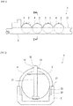
- Fig. 1 is a side view of a liquefied gas carrying vessel 1 according to the embodiment.
- a plurality (four in this example) of tanks 3 that stores liquefied gas is arranged at a hull 2 of the liquefied gas carrying vessel 1 in a longitudinal direction of the hull.
- the liquefied gas stored in the tanks 3 is, for example, liquefied natural gas (LNG), LPQ or liquid hydrogen.
- the tank 3 is a MOSS type spherical tank. Although it has been described in the present embodiment that the tank 3 is a true sphere, for example, the tank 3 may be a cylindrical vertical tank having a shape that forms a part of a hemisphere at the top, or may be a substantially spherical shape which is a non-spherical shape. An outer surface of the tank 3 is covered with a heat insulating material (not illustrated). An upper portion of the tank 3 protrudes above an upper deck 21 of the hull 2. In addition, tank covers 4 that respectively cover upper portions of the tanks 3 protruding above the upper deck 21 are provided at the upper deck 21.
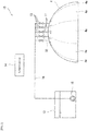
- Fig. 2 is a cross-sectional view of the liquefied gas carrying vessel 1 taken along a line II-II illustrated in Fig. 1.
- Fig. 2 schematically illustrates a structure for supporting the tank 3.
- a foundation deck 22 is provided around the tank 3 and below the upper deck 21 of the hull 2.
- a cylindrical skirt 23 that supports the tank 3 is provided at the foundation deck 22.
- a pipe tower 31 is provided at a center of the tank 3 so as to extend vertically.
- the pipe tower 31 accommodates handling piping and pumps (not illustrated).
- a tank dome 32 is provided at a top portion of the tank 3.
- the tank dome 32 has an entrance that guides a plurality of pipes such as handling pipes from outside the tank 3 to the pipe tower 31.
- a lower end portion of the tank cover 4 is supported by the upper deck 21.
- the tank cover 4 has a hemispherical shape, and spreads along an outer surface of the upper portion of the tank 3 at a predetermined distance outside the tank 3.
- the tank dome 32 protrudes from a center of the tank cover 4, and is covered by a dome cover (not illustrated).
- a plurality of nozzles 11 that injects cooling water to an outer surface of the tank cover 4 is arranged outside the tank cover 4.
- the liquefied gas carrying vessel 1 of the present embodiment includes a cooling system 10 that cools the tank cover 4 by injecting the cooling water from the plurality of nozzles 11.
- Fig. 3 is a schematic diagram illustrating a configuration of the cooling system 10. Although only one tank cover 4 of the four tank covers 4 included in the liquefied gas carrying vessel 1 is illustrated in Fig. 3 , the cooling system 10 is provided for each of the four tank covers 4.
- the cooling system 10 includes the plurality of nozzles 11, a storage tank 12 that stores the cooling water, a plurality of opening and closing valves 13 provided so as to correspond to the plurality of nozzles 11, and a control device 14.
- a pump 15 is disposed within the storage tank 12, and a supply line 16 extends from the pump 15 to the nozzles 11.
- the cooling water within the storage tank 12 is taken out of the storage tank 12 by the supply line 16, and is guided to each of the plurality of nozzles 11.
- the cooling water may be supplied to the nozzle 11 by charging the storage tank 12 with air or a gas such as nitrogen and pressurizing the cooling water instead of operating the pump 15.
- Fig. 4 is a top view of the tank cover 4.
- the plurality of nozzles 11 is schematically illustrated, and pipes for guiding the cooling water to each nozzle 11 are omitted.
- the nozzle 11 is a spray nozzle, and injects the cooling water to the outer surface of the tank cover 4 while diffusing the cooling water.
- the plurality of nozzles 11 is arranged at an upper portion of the tank cover 4 so as to be arranged in a circumferential direction in planer view. Specifically, the plurality of nozzles 11 is arranged around the tank dome 32, for example, around a dome cover (not illustrated) at intervals along the circumferential direction.
- the tank cover 4 has a plurality of cooling target regions 4a corresponding to the plurality of nozzles 11.
- the cooling target region 4a is a partial region of the tank cover 4 to be cooled by the cooling water injected from the corresponding nozzle 11.
- a boundary between two adjacent cooling target regions 4a is represented by a broken line.
- the cooling target regions 4a are formed by dividing the tank cover 4 into the same number of regions as the number of nozzles 11 in the circumferential direction in planar view.
- the cooling target region 4a includes a location to which the cooling water is directly injected from the nozzle 11 and a location with which the injected cooling water flows downward and comes in contact.
- the storage tank 12 stores fresh water as the cooling water.
- the fresh water is generated from seawater by a fresh water generation device (not illustrated) provided at the hull 2.
- the storage tank 12 may be provided for each tank cover 4, or one common storage tank 12 may be provided for the plurality of tank covers 4.
- the opening and closing valve 13 is an automatic valve that is controlled so as to be opened and closed based on a determination result of the control device 14 to be described below.
- the opening and closing valve 13 is opened, the injection of the cooling water from the corresponding nozzle 11 is started, and when the opening and closing valve 13 is closed, the injection of the cooling water from the corresponding nozzle 11 is stopped.
- the control device 14 is, for example, a computer, and includes an arithmetic processing unit such as a CPU and a storage unit such as a ROM and a RAM (all not illustrated).
- the storage unit stores programs executed by the arithmetic processing unit and various fixed data.
- the arithmetic processing unit transmits and receives data to and from an external device, receives signals input from various instruments, and outputs control signals to control targets.
- the arithmetic processing unit t reads and executes software such as the program stored in the storage unit, and thus, processing for controlling the cooling system 10 is performed in the control device 14.
- the control device 14 may execute each processing through centralized control using a single computer, or may execute each processing through distributed control by cooperation of a plurality of computers.
- Fig. 5 is a block diagram illustrating a functional configuration of the control device 14 in the cooling system 10.
- the arithmetic processing unit executes various programs stored in the storage unit, and thus, the control device 14 functions as a determination heat amount calculation unit 51, an opening and closing determination unit 52, a vaporization rate calculation unit 53, and an opening and closing valve control unit 54.
- the determination heat amount calculation unit 51 calculates a determination heat amount based on a convective heat transfer amount and a solar irradiation amount for each of the plurality of cooling target regions 4a.
- the determination heat amount is a value as an index for determining whether or not to open each the opening and closing valve 13.
- the determination heat amount calculation unit 51 calculates the convective heat transfer amount and the solar irradiation amount for each opening and closing valve 13, that is, for each cooling target region 4a, and calculates the determination heat amount by using the following Equation (1).
- determination heat amount convective heat transfer amount + solar irradiation amount
- the convective heat transfer amount is a heat amount transferred to the cooling target region 4a from outside air around the tank cover 4, that is, from atmosphere with which the outer surface of the tank cover 4 is in contact.
- the convective heat transfer amount is calculated from a direction and a speed of wind blowing against the liquefied gas carrying vessel 1 (wind direction and wind speed data), a speed and a direction of the liquefied gas carrying vessel 1 (ship speed and ship direction data), an atmospheric temperature around the liquefied gas carrying vessel 1 (atmospheric temperature data), etc.
- the solar irradiation amount is a heat amount transferred to the cooling target region 4a by solar irradiation.
- the solar irradiation amount is, for example, a latitude and a longitude of a position of the liquefied gas carrying vessel 1 and an orientation of the liquefied gas carrying vessel 1 (ship position and ship direction data), a solar altitude, a direct solar irradiation amount and a sky solar irradiation amount decided by a cloud amount, etc.
- an atmospheric longwave radiation amount may be considered.
- the control device 14 receives weather data from an external agency on land via a communication device (not illustrated) provided on the hull 2, and acquires the wind direction and wind speed data, the atmospheric temperature data, and the solar irradiation related data from the weather data.
- a communication device not illustrated
- An anemometer may be provided on the hull 2, and the control device 14 may acquire the wind speed and wind direction data from the anemometer.
- a thermometer and a solar irradiation value meter may be provided on the hull 2, and the control device 14 may acquire the atmospheric temperature data and the solar irradiation related data from the solar irradiation value meter.
- Fig. 6 is an example of a distribution of the convective heat transfer amount transferred from the atmosphere to the tank cover 4
- Fig. 7 is an example of a distribution of the solar irradiation amount transferred to the tank cover 4 by the solar irradiation at a certain time.
- Figs. 6 and 7 are diagrams of the tank cover 4 when viewed from above. Also, in Figs. 6 and 7 , an upper side of the paper, a lower side of the paper, a right side of the paper, and a left side of the paper correspond to a left side, a right side, a front side, and a rear side in a traveling direction of the liquefied gas carrying vessel 1.
- the amount of cooling water stored in the storage tank 12 is limited, it is desirable that a temperature rise of the tank cover 4 is efficiently suppressed with a small injection amount.
- the atmosphere flows from the front side to the rear side of the tank cover 4, and thus, the convective heat transfer amount becomes large in a region on the front side of the tank cover 4.
- the sun is located on the right side of the tank cover 4, and the solar irradiation amount becomes large in a region on the right side of the tank cover 4.
- the cooling target region 4a to be cooled (the opening and closing valve 13 to be opened) is decided by comprehensively determining the influence of the convective heat transfer amount and the solar irradiation amount by using the determination heat amount.
- the opening and closing determination unit 52 determines whether or not to open each opening and closing valve 13 based on the determination heat amount calculated by the determination heat amount calculation unit 51. Specifically, a threshold value is set for the determination heat amount of each cooling target region 4a, and the opening and closing determination unit 52 decides whether or not to open each opening and closing valve 13 by determining whether or not each determination heat amount exceeds the threshold value. The opening and closing determination unit 52 decides to open the corresponding opening and closing valve 13 when the determination heat amount exceeds the threshold value, and the opening and closing determination unit 52 determines to maintain a state in which the corresponding opening and closing valve 13 is closed when the determination heat amount does not exceed the threshold value.
- the vaporization rate calculation unit 53 calculates a natural vaporization rate of the liquefied gas within the tank 3 per predetermined time.
- the vaporization rate calculated by the vaporization rate calculation unit 53 (hereinafter, referred to as a "calculated vaporization rate") is used for deciding the injection amount of cooling water from each nozzle 11 by the opening and closing determination unit 52.
- the calculated vaporization rate is a ratio of a volume change per unit day (V1 - V2) to a liquefied gas volume V1 within the tank 3, and is calculated by the following Equation (2).
- V1 and V2 are acquired based on a liquid level gauge (not illustrated) and a tank table (a table in which actual liquefied gas volume is deduced from temperatures and densities of a gas layer and a liquid layer within the tank 3, trim and list of the vessel, and a liquid level of the liquid level gauge) provided at the tank 3. Details of the method for deciding the injection amount will be described below.
- the opening and closing valve control unit 54 sends a control signal to each opening and closing valve 13 based on the determination result using the opening and closing determination unit 52.
- the natural vaporization rate at which the liquefied gas is naturally vaporized within the tank 3 during the entire operation period from when the liquefied gas carrying vessel departs from the port to when the liquefied gas carrying vessel enters the port is predicted before the liquefied gas carrying vessel 1 departs from a port.
- the predicted vaporization rate is referred to as a "predicted vaporization rate”.
- Fig. 8 is a graph illustrating an example of a temporal change of the predicted vaporization rate in the entire operation.
- the predicted vaporization rate is predicted from, for example, a sea weather condition and a route plan.
- a time zone (spray time zone) in which the control device 14 executes the determination processing is planned from the temporal change of the predicted vaporization rate.
- an average value of the predicted vaporization rates in the entire operation is set as a predicted average vaporization rate, and when the predicted average vaporization rate exceeds a target vaporization rate, a time zone in which the fluctuating predicted vaporization rate exceeds the target vaporization rate is set as the spray time zone.
- the setting of the spray time zone is not limited thereto.
- a time zone in which the calculated vaporization rate calculated by the vaporization rate calculation unit 53 at a predetermined time after the liquefied gas carrying vessel departs the port exceeds the target vaporization rate may be set as the spray time zone (See Fig. 8 ).
- the control device 14 executes the determination processing in the planned spray time zone. Specifically, the control device 14 executes the determination processing at predetermined time intervals (for example, one hour) in the spray time zone.
- the determination heat amount calculation unit 51 calculates the determination heat amount based on the convective heat transfer amount and the solar irradiation amount for each of the plurality of cooling target regions 4a. Subsequently, the opening and closing determination unit 52 determines whether or not the determination heat amount exceeds the threshold value for each of the plurality of cooling target regions 4a. By doing this, the opening and closing determination unit 52 decides the opening and closing valve 13 to be opened from the plurality of opening and closing valves 13.
- the opening and closing determination unit 52 determines the injection amount of the cooling water from each nozzle 11 based on the calculated vaporization rate calculated by the vaporization rate calculation unit 53. Specifically, for example, the control device 14 sets the injection amount of the cooling water corresponding to the determination heat amount in advance such that as the determination heat amount becomes large, the injection amount becomes large.
- the opening and closing determination unit 52 decides the injection amount which is larger than the set injection amount.
- the opening and closing determination unit 52 decides the set injection amount or the injection amount which is smaller than the set injection amount.
- the opening and closing determination unit 52 may decide an injection time, that is, a time during which the opening and closing valve 13 is opened instead of the injection amount.
- the opening and closing determination unit 52 may decide to expand an injection range instead of the injection amount.
- the opening and closing valve control unit 54 of the control device 14 sends the control signal to the opening and closing valve 13.
- the aforementioned plan is an example of the spray plan based on the sea weather prediction and the route plan before departure. Actually, sea weather data is updated at any time, or various amounts are decided according to the actual route.
- the liquefied gas carrying vessel 1 can reduce the temperature of the tank cover 4 by injecting the cooling water to the outer surface of the tank cover 4. Accordingly, the heat amount transferred from the tank cover 4 to the gas between the tank 3 and the tank cover 4 can be reduced, and the temperature rise of the gas around the tank 3 can be consequently suppressed. Therefore, it is possible to reduce heat entering the tank 3 from the outside.
- a location of the tank cover 4 at which the heat amount transferred from the outside is large can be mainly cooled by appropriately opening and closing the opening and closing valve 13 by using the determination result.
- the cooling water injected from each spray nozzle flows downward along a hemispherical surface of the tank cover 4 due to gravity.
- a scaffold of a crew is usually constructed around the tank dome 32.
- the nozzles 11 and the opening and closing valves 13 corresponding to the nozzles are provided at the upper portion of the tank cover 4, and thus, it is easy to perform the maintenance of the nozzles 11 and the opening and closing valves 13.
- the number and arrangement method of the nozzles 11 are not limited to those described in the aforementioned embodiment. Although it has been described in the aforementioned embodiment that the nozzles 11 are arranged around the tank dome 32, the nozzles 11 may be arranged at a position not only around the tank dome 32 but also above the upper deck 21 and below the tank dome 32 in the tank cover 4, for example.
- the shape of the tank cover to be cooled is also not limited to the shape described in the aforementioned embodiment, but may not be a hemisphere. Although it has been described in the aforementioned embodiment that one tank cover is provided for one tank 3, the tank cover may cover the plurality of tanks 3.
- the present invention is applicable not only to the spherical tank but also to a tank cover that covers other types of tanks such as a membrane tank. Further, in order to avoid water repellency of the cooling water, a paint or a baffle plate having excellent water absorption may be applied to the tank cover.
- the cooling water may be seawater.
- the seawater may be stored in the storage tank 12, or the seawater around the hull 2 may be directly supplied to the nozzle 11 without passing through the storage tank 12.
- the opening and closing valve 13 is an automatic valve that is automatically opened and closed based on the determination result of the opening and closing determination unit 52
- the opening and closing valve 13 may be a manual valve that is opened and closed by manually operating an operation unit by the crew.
- the control device 14 may include a notification device that notifies the crew of the determination result by the opening and closing determination unit 52.
- the notification device may be a display that displays the determination result using the opening and closing determination unit 52, or a lamp that is turned on according to the determination result. Since the crew is notified of the determination result of the opening and closing determination unit 52 from the notification device, it is possible to appropriately operate the manual valve determined to be opened.
- the method of calculating the determination heat amount for determining whether or not to open each opening and closing valve 13 is not limited thereto.
- a value obtained by multiplying one or both of the calculated convective heat transfer amount and solar irradiation amount by contribution rates ⁇ and ⁇ and adding the multiplied values may be used as the determination heat amount as in the following equation (3).
- determination heat amount ⁇ ⁇ convective heat transfer amount + ⁇ ⁇ solar irradiation amount
- a timing at which the determination processing is executed is not limited thereto. For example, it may not be necessary to set the spray time zone, and the determination processing may be executed when another condition is satisfied not at predetermined time intervals. For example, when the calculated vaporization rate of the liquefied gas calculated by the vaporization rate calculation unit 53 during an actual voyage exceeds a predetermined threshold value, the control device 14 may execute the determination processing. Further, spraying may be performed when a tank pressure exceeds a predetermined operating pressure.
- the opening and closing determination unit 52 may not decide the opening and closing valve to be opened based on whether or not the determination heat amount exceeds the threshold value. For example, the opening and closing determination unit 52 may decide, as the opening and closing valve to be opened, the opening and closing valve corresponding to the cooling target region 4a at which the calculated convective heat transfer amount is the maximum. Alternatively, the opening and closing determination unit 52 may decide, as the opening and closing valve to be opened, the opening and closing valve corresponding to the cooling target region 4a at which the calculated solar irradiation amount is the maximum.
- the opening and closing determination unit 52 may decide, as the opening and closing valve to be opened, the opening and closing valve corresponding to the cooling target region 4a at which the calculated convective heat transfer amount is the maximum and the opening and closing valve corresponding to the cooling target region 4a at which the calculated solar irradiation amount is the maximum.
- valve opening times of these opening and closing valves may be adjusted based on a ratio between the convective heat transfer amount and the solar irradiation amount.
Landscapes
- Engineering & Computer Science (AREA)
- Mechanical Engineering (AREA)
- General Engineering & Computer Science (AREA)
- Chemical & Material Sciences (AREA)
- Combustion & Propulsion (AREA)
- Ocean & Marine Engineering (AREA)
- Physics & Mathematics (AREA)
- Thermal Sciences (AREA)
- Filling Or Discharging Of Gas Storage Vessels (AREA)
Abstract
Description
- The present invention relates to a liquefied gas carrying vessel including a tank that stores a liquefied gas and a tank cover that covers the tank.
- A liquefied gas carrying vessel that carries a liquefied natural gas (LNG) transports the liquefied gas loaded within a tank at a loading port to a discharge port while cold-insulating the liquefied gas cool. During transportation, the liquefied gas is naturally evaporated due to heat input from outside air and a boil-off gas is generated within the tank. A natural vaporization rate (boil-off rate) is one of indices that influence the worth of a ship, and development for reducing the natural vaporization rate has been conducted.
- For example,
PTL 1 discloses a liquefied gas carrying vessel that includes a tank which stores a liquefied gas therein, a hull which has a tank accommodation unit accommodating the tank, and a heat insulator body which is supported by the tank accommodation unit so as to surround the tank. In this liquefied gas carrying vessel, even though a heat insulating material is thickened and a weight of the heat insulating material is increased, the heat insulating material is intended to be reliably supported by the tank accommodation unit. An upper portion of the tank is covered with a tank cover provided at an upper deck of the hull. - PTL 1:
JP 2016-16806 A - An increase in the thickness of the heat insulating material provided in the tank leads to an increase in a ship width. In recent years, there is a need to increase a tank capacity, but the propulsion performance of the ship is deteriorated by the increase in the ship width. It is difficult to increase a horizontal width of the ship in the liquefied gas carrying vessel due to restrictions (currently 49 m) on the New Panama Canal Channel. Thus, as a means for reducing heat entering the tank from the outside air, another measure is required instead of increasing the thickness of the heat insulating material.
- Therefore, an object of the present invention is to provide a liquefied gas carrying vessel capable of reducing heat entering a tank from outside air while suppressing a thickness of a heat insulating material with respect to the tank that stores a liquefied gas.
- In order to solve the above problems, the inventors of the present invention has found that when the tank cover becomes a high temperature by being heated by the outside air and solar irradiation around the tank cover, a temperature of the gas between the tank and the tank cover is increased by the heat transferred from the tank cover and the heat entering the tank is also increased. The present invention has been made from such a viewpoint.
- That is, a liquefied gas carrying vessel according to the present invention a tank that stores a liquefied gas, a tank cover that covers the tank, and a plurality of nozzles that is arranged outside the tank cover, and injects cooling water to an outer surface of the tank cover.
- According to the aforementioned configuration, it is possible to reduce the temperature of the tank cover by injecting the cooling water to the outer surface of the tank cover. Accordingly, the heat amount transferred from the tank cover to the gas between the tank and the tank cover can be reduced, and the temperature rise of the gas around the tank can be consequently suppressed. Therefore, it is possible to reduce heat entering the tank from the outside.
- In the liquefied gas carrying vessel, the tank cover may have a plurality of cooling target regions corresponding to the plurality of nozzles, and the liquefied gas carrying vessel may further include a plurality of opening and closing valves that is provided so as to correspond to the plurality of nozzles, a heat amount calculation unit that calculates a determination heat amount based on at least one of a convective heat transfer amount which is a heat amount transferred from outside air around the tank cover and a solar irradiation amount which is a heat amount transferred by solar irradiation for each of the plurality of cooling target regions, and an opening and closing determination unit that determines whether or not to open each of the plurality of opening and closing valves based on the calculated determination heat amount. According to this configuration, since it is determined whether or not to open each of the plurality of opening and closing valves based on the determination heat amount of each of the cooling target regions, a location of the tank cover at which the heat amount transferred from the outside is large can be mainly cooled by appropriately opening and closing the opening and closing valve by using the determination result.
- In the liquefied gas carrying vessel, the tank cover may have a hemispherical shape, and the plurality of nozzles may be arranged at an upper portion of the tank cover so as to be arranged in a circumferential direction in planar view, and the nozzle may be a spray nozzle that injects the cooling water to the outer surface of the tank cover while diffusing the cooling water. According to this configuration, at the upper portion of the tank cover, the cooling water injected from each spray nozzle flows downward along a hemispherical surface of the tank cover due to gravity. Thus, not only the location of the outer surface of the tank cover to which the cooling water is directly injected but also the location with which the cooling water comes in contact by flowing along the hemispherical surface of the tank cover can be cooled. Therefore, the tank cover can be efficiently cooled.
- According to the present invention, it is possible to provide a liquefied gas carrying vessel capable of reducing heat entering a tank from outside air while suppressing a thickness of a heat insulating material with respect to a tank that stores a liquefied gas.
-
-
Fig. 1 is a side view of a liquefied gas carrying vessel according to an embodiment of the present invention. -
Fig. 2 is a cross-sectional view of the liquefied gas carrying vessel taken along a line II-II illustrated inFig. 1 . -
Fig. 3 is a schematic diagram illustrating a configuration of a cooling system provided in the liquefied gas carrying vessel illustrated inFig. 1 . -
Fig. 4 is a top view of a tank cover provided in the liquefied gas carrying vessel illustrated inFig. 1 . -
Fig. 5 is a block diagram illustrating a functional configuration of a control device in the cooling system illustrated inFig. 4 . -
Fig. 6 is a top view of the tank cover schematically illustrating an example of a distribution of the heat amount transferred from atmosphere to the tank cover. -
Fig. 7 is a top view of the tank cover schematically illustrating an example of a distribution of the heat amount transferred to the tank cover by solar radiation. -
Fig. 8 is a graph illustrating an example of a temporal change of a predicted natural vaporization rate and a spray time zone. - Hereinafter, a liquefied gas carrying vessel according to an embodiment of the present invention will be described with reference to the drawings.
-
Fig. 1 is a side view of a liquefiedgas carrying vessel 1 according to the embodiment. A plurality (four in this example) oftanks 3 that stores liquefied gas is arranged at ahull 2 of the liquefiedgas carrying vessel 1 in a longitudinal direction of the hull. The liquefied gas stored in thetanks 3 is, for example, liquefied natural gas (LNG), LPQ or liquid hydrogen. - The
tank 3 is a MOSS type spherical tank. Although it has been described in the present embodiment that thetank 3 is a true sphere, for example, thetank 3 may be a cylindrical vertical tank having a shape that forms a part of a hemisphere at the top, or may be a substantially spherical shape which is a non-spherical shape. An outer surface of thetank 3 is covered with a heat insulating material (not illustrated). An upper portion of thetank 3 protrudes above anupper deck 21 of thehull 2. In addition, tank covers 4 that respectively cover upper portions of thetanks 3 protruding above theupper deck 21 are provided at theupper deck 21. -
Fig. 2 is a cross-sectional view of the liquefiedgas carrying vessel 1 taken along a line II-II illustrated inFig. 1. Fig. 2 schematically illustrates a structure for supporting thetank 3. Afoundation deck 22 is provided around thetank 3 and below theupper deck 21 of thehull 2. Acylindrical skirt 23 that supports thetank 3 is provided at thefoundation deck 22. Apipe tower 31 is provided at a center of thetank 3 so as to extend vertically. Thepipe tower 31 accommodates handling piping and pumps (not illustrated). Atank dome 32 is provided at a top portion of thetank 3. Thetank dome 32 has an entrance that guides a plurality of pipes such as handling pipes from outside thetank 3 to thepipe tower 31. - A lower end portion of the
tank cover 4 is supported by theupper deck 21. Thetank cover 4 has a hemispherical shape, and spreads along an outer surface of the upper portion of thetank 3 at a predetermined distance outside thetank 3. Thetank dome 32 protrudes from a center of thetank cover 4, and is covered by a dome cover (not illustrated). - In the present embodiment, a plurality of
nozzles 11 that injects cooling water to an outer surface of thetank cover 4 is arranged outside thetank cover 4. The liquefiedgas carrying vessel 1 of the present embodiment includes acooling system 10 that cools thetank cover 4 by injecting the cooling water from the plurality ofnozzles 11. -
Fig. 3 is a schematic diagram illustrating a configuration of thecooling system 10. Although only onetank cover 4 of the four tank covers 4 included in the liquefiedgas carrying vessel 1 is illustrated inFig. 3 , thecooling system 10 is provided for each of the four tank covers 4. - The
cooling system 10 includes the plurality ofnozzles 11, astorage tank 12 that stores the cooling water, a plurality of opening and closingvalves 13 provided so as to correspond to the plurality ofnozzles 11, and acontrol device 14. Apump 15 is disposed within thestorage tank 12, and asupply line 16 extends from thepump 15 to thenozzles 11. The cooling water within thestorage tank 12 is taken out of thestorage tank 12 by thesupply line 16, and is guided to each of the plurality ofnozzles 11. The cooling water may be supplied to thenozzle 11 by charging thestorage tank 12 with air or a gas such as nitrogen and pressurizing the cooling water instead of operating thepump 15. -
Fig. 4 is a top view of thetank cover 4. InFig. 4 , the plurality ofnozzles 11 is schematically illustrated, and pipes for guiding the cooling water to eachnozzle 11 are omitted. Thenozzle 11 is a spray nozzle, and injects the cooling water to the outer surface of thetank cover 4 while diffusing the cooling water. The plurality ofnozzles 11 is arranged at an upper portion of thetank cover 4 so as to be arranged in a circumferential direction in planer view. Specifically, the plurality ofnozzles 11 is arranged around thetank dome 32, for example, around a dome cover (not illustrated) at intervals along the circumferential direction. - The
tank cover 4 has a plurality of coolingtarget regions 4a corresponding to the plurality ofnozzles 11. Thecooling target region 4a is a partial region of thetank cover 4 to be cooled by the cooling water injected from the correspondingnozzle 11. InFig. 4 , a boundary between two adjacentcooling target regions 4a is represented by a broken line. As illustrated inFig. 4 , the coolingtarget regions 4a are formed by dividing thetank cover 4 into the same number of regions as the number ofnozzles 11 in the circumferential direction in planar view. Thecooling target region 4a includes a location to which the cooling water is directly injected from thenozzle 11 and a location with which the injected cooling water flows downward and comes in contact. - Referring back to
Fig. 3 , thestorage tank 12 stores fresh water as the cooling water. For example, the fresh water is generated from seawater by a fresh water generation device (not illustrated) provided at thehull 2. At thehull 2, thestorage tank 12 may be provided for eachtank cover 4, or onecommon storage tank 12 may be provided for the plurality of tank covers 4. - The opening and closing
valve 13 is an automatic valve that is controlled so as to be opened and closed based on a determination result of thecontrol device 14 to be described below. When the opening and closingvalve 13 is opened, the injection of the cooling water from the correspondingnozzle 11 is started, and when the opening and closingvalve 13 is closed, the injection of the cooling water from the correspondingnozzle 11 is stopped. - The
control device 14 is, for example, a computer, and includes an arithmetic processing unit such as a CPU and a storage unit such as a ROM and a RAM (all not illustrated). The storage unit stores programs executed by the arithmetic processing unit and various fixed data. The arithmetic processing unit transmits and receives data to and from an external device, receives signals input from various instruments, and outputs control signals to control targets. The arithmetic processing unit t reads and executes software such as the program stored in the storage unit, and thus, processing for controlling thecooling system 10 is performed in thecontrol device 14. Thecontrol device 14 may execute each processing through centralized control using a single computer, or may execute each processing through distributed control by cooperation of a plurality of computers. -
Fig. 5 is a block diagram illustrating a functional configuration of thecontrol device 14 in thecooling system 10. For example, the arithmetic processing unit executes various programs stored in the storage unit, and thus, thecontrol device 14 functions as a determination heatamount calculation unit 51, an opening andclosing determination unit 52, a vaporizationrate calculation unit 53, and an opening and closingvalve control unit 54. - The determination heat
amount calculation unit 51 calculates a determination heat amount based on a convective heat transfer amount and a solar irradiation amount for each of the plurality of coolingtarget regions 4a. In the present embodiment, the determination heat amount is a value as an index for determining whether or not to open each the opening and closingvalve 13. The determination heatamount calculation unit 51 calculates the convective heat transfer amount and the solar irradiation amount for each opening and closingvalve 13, that is, for eachcooling target region 4a, and calculates the determination heat amount by using the following Equation (1).
- In the above Equation (1), the convective heat transfer amount is a heat amount transferred to the
cooling target region 4a from outside air around thetank cover 4, that is, from atmosphere with which the outer surface of thetank cover 4 is in contact. For example, the convective heat transfer amount is calculated from a direction and a speed of wind blowing against the liquefied gas carrying vessel 1 (wind direction and wind speed data), a speed and a direction of the liquefied gas carrying vessel 1 (ship speed and ship direction data), an atmospheric temperature around the liquefied gas carrying vessel 1 (atmospheric temperature data), etc. - In the above Equation (1), the solar irradiation amount is a heat amount transferred to the
cooling target region 4a by solar irradiation. The solar irradiation amount is, for example, a latitude and a longitude of a position of the liquefiedgas carrying vessel 1 and an orientation of the liquefied gas carrying vessel 1 (ship position and ship direction data), a solar altitude, a direct solar irradiation amount and a sky solar irradiation amount decided by a cloud amount, etc. In addition, an atmospheric longwave radiation amount may be considered. - For example, the
control device 14 receives weather data from an external agency on land via a communication device (not illustrated) provided on thehull 2, and acquires the wind direction and wind speed data, the atmospheric temperature data, and the solar irradiation related data from the weather data. An anemometer may be provided on thehull 2, and thecontrol device 14 may acquire the wind speed and wind direction data from the anemometer. Alternatively, a thermometer and a solar irradiation value meter may be provided on thehull 2, and thecontrol device 14 may acquire the atmospheric temperature data and the solar irradiation related data from the solar irradiation value meter. -
Fig. 6 is an example of a distribution of the convective heat transfer amount transferred from the atmosphere to thetank cover 4, andFig. 7 is an example of a distribution of the solar irradiation amount transferred to thetank cover 4 by the solar irradiation at a certain time.Figs. 6 and 7 are diagrams of thetank cover 4 when viewed from above. Also, inFigs. 6 and 7 , an upper side of the paper, a lower side of the paper, a right side of the paper, and a left side of the paper correspond to a left side, a right side, a front side, and a rear side in a traveling direction of the liquefiedgas carrying vessel 1. - Since the amount of cooling water stored in the
storage tank 12 is limited, it is desirable that a temperature rise of thetank cover 4 is efficiently suppressed with a small injection amount. In the example illustrated inFig. 6 , the atmosphere flows from the front side to the rear side of thetank cover 4, and thus, the convective heat transfer amount becomes large in a region on the front side of thetank cover 4. Thus, in order to suppress the temperature rise of thetank cover 4 due to the convective heat transfer amount, it is efficient to intensively inject the cooling water to thecooling target region 4a located on the front side. In the example illustrated inFig. 7 , the sun is located on the right side of thetank cover 4, and the solar irradiation amount becomes large in a region on the right side of thetank cover 4. Thus, in order to suppress the temperature rise of thetank cover 4 due to the solar irradiation amount, it is efficient to intensively inject the cooling water to thecooling target region 4a located on the right side. In the present embodiment, in order to efficiently cool thetank cover 4, thecooling target region 4a to be cooled (the opening and closingvalve 13 to be opened) is decided by comprehensively determining the influence of the convective heat transfer amount and the solar irradiation amount by using the determination heat amount. - Referring back to
Fig. 5 , the opening andclosing determination unit 52 determines whether or not to open each opening and closingvalve 13 based on the determination heat amount calculated by the determination heatamount calculation unit 51. Specifically, a threshold value is set for the determination heat amount of eachcooling target region 4a, and the opening andclosing determination unit 52 decides whether or not to open each opening and closingvalve 13 by determining whether or not each determination heat amount exceeds the threshold value. The opening andclosing determination unit 52 decides to open the corresponding opening and closingvalve 13 when the determination heat amount exceeds the threshold value, and the opening andclosing determination unit 52 determines to maintain a state in which the corresponding opening and closingvalve 13 is closed when the determination heat amount does not exceed the threshold value. - The vaporization
rate calculation unit 53 calculates a natural vaporization rate of the liquefied gas within thetank 3 per predetermined time. In the present embodiment, the vaporization rate calculated by the vaporization rate calculation unit 53 (hereinafter, referred to as a "calculated vaporization rate") is used for deciding the injection amount of cooling water from eachnozzle 11 by the opening andclosing determination unit 52. For example, the calculated vaporization rate is a ratio of a volume change per unit day (V1 - V2) to a liquefied gas volume V1 within thetank 3, and is calculated by the following Equation (2).
tank 3, trim and list of the vessel, and a liquid level of the liquid level gauge) provided at thetank 3. Details of the method for deciding the injection amount will be described below. - The opening and closing
valve control unit 54 sends a control signal to each opening and closingvalve 13 based on the determination result using the opening andclosing determination unit 52. - Next, a flow of determination processing for determining whether or not to open the opening and closing
valve 13 by thecontrol device 14 will be described. - Initially, as a preparation for performing the determination processing during the operation of the liquefied
gas carrying vessel 1, the natural vaporization rate at which the liquefied gas is naturally vaporized within thetank 3 during the entire operation period from when the liquefied gas carrying vessel departs from the port to when the liquefied gas carrying vessel enters the port is predicted before the liquefiedgas carrying vessel 1 departs from a port. Hereinafter, the predicted vaporization rate is referred to as a "predicted vaporization rate".Fig. 8 is a graph illustrating an example of a temporal change of the predicted vaporization rate in the entire operation. The predicted vaporization rate is predicted from, for example, a sea weather condition and a route plan. A time zone (spray time zone) in which thecontrol device 14 executes the determination processing is planned from the temporal change of the predicted vaporization rate. In the example illustrated inFig. 8 , an average value of the predicted vaporization rates in the entire operation is set as a predicted average vaporization rate, and when the predicted average vaporization rate exceeds a target vaporization rate, a time zone in which the fluctuating predicted vaporization rate exceeds the target vaporization rate is set as the spray time zone. - The setting of the spray time zone is not limited thereto. For example, a time zone in which the calculated vaporization rate calculated by the vaporization
rate calculation unit 53 at a predetermined time after the liquefied gas carrying vessel departs the port exceeds the target vaporization rate may be set as the spray time zone (SeeFig. 8 ). - During a period from when the liquefied
gas carrying vessel 1 departs the port and to when the liquefied gas carrying vessel enters the port, thecontrol device 14 executes the determination processing in the planned spray time zone. Specifically, thecontrol device 14 executes the determination processing at predetermined time intervals (for example, one hour) in the spray time zone. - Initially, in the determination processing, the determination heat
amount calculation unit 51 calculates the determination heat amount based on the convective heat transfer amount and the solar irradiation amount for each of the plurality of coolingtarget regions 4a. Subsequently, the opening andclosing determination unit 52 determines whether or not the determination heat amount exceeds the threshold value for each of the plurality of coolingtarget regions 4a. By doing this, the opening andclosing determination unit 52 decides the opening and closingvalve 13 to be opened from the plurality of opening and closingvalves 13. - In addition, the opening and
closing determination unit 52 determines the injection amount of the cooling water from eachnozzle 11 based on the calculated vaporization rate calculated by the vaporizationrate calculation unit 53. Specifically, for example, thecontrol device 14 sets the injection amount of the cooling water corresponding to the determination heat amount in advance such that as the determination heat amount becomes large, the injection amount becomes large. When the calculated vaporization rate is equal to or higher than the target vaporization rate, the opening andclosing determination unit 52 decides the injection amount which is larger than the set injection amount. When the calculated vaporization rate is lower than the target vaporization rate, the opening andclosing determination unit 52 decides the set injection amount or the injection amount which is smaller than the set injection amount. Alternatively, the opening andclosing determination unit 52 may decide an injection time, that is, a time during which the opening and closingvalve 13 is opened instead of the injection amount. The opening andclosing determination unit 52 may decide to expand an injection range instead of the injection amount. - By doing this, when the injection amount from the
nozzle 11 corresponding to the opening and closingvalve 13 to be opened is decided by the determination processing using thecontrol device 14, the opening and closingvalve control unit 54 of thecontrol device 14 sends the control signal to the opening and closingvalve 13. The aforementioned plan is an example of the spray plan based on the sea weather prediction and the route plan before departure. Actually, sea weather data is updated at any time, or various amounts are decided according to the actual route. - As described above, the liquefied
gas carrying vessel 1 according to the present embodiment can reduce the temperature of thetank cover 4 by injecting the cooling water to the outer surface of thetank cover 4. Accordingly, the heat amount transferred from thetank cover 4 to the gas between thetank 3 and thetank cover 4 can be reduced, and the temperature rise of the gas around thetank 3 can be consequently suppressed. Therefore, it is possible to reduce heat entering thetank 3 from the outside. - Further, in the present embodiment, since it is determined whether or not to open each of the plurality of opening and closing
valves 13 based on the determination heat amount of each of thecooling target regions 4a, a location of thetank cover 4 at which the heat amount transferred from the outside is large can be mainly cooled by appropriately opening and closing the opening and closingvalve 13 by using the determination result. - Further, in the present embodiment, at the upper portion of the
tank cover 4, the cooling water injected from each spray nozzle flows downward along a hemispherical surface of thetank cover 4 due to gravity. Thus, not only the location of the outer surface of thetank cover 4 to which the cooling water is directly injected but also the location with which the cooling water comes in contact by flowing along the hemispherical surface of thetank cover 4 can be cooled. Therefore, thetank cover 4 can be efficiently cooled. A scaffold of a crew is usually constructed around thetank dome 32. Thenozzles 11 and the opening and closingvalves 13 corresponding to the nozzles are provided at the upper portion of thetank cover 4, and thus, it is easy to perform the maintenance of thenozzles 11 and the opening and closingvalves 13. - The aforementioned embodiment is illustrative in all aspects, and should not be considered as limiting. The scope of the present invention is defined by the claims rather than the above description, and is intended to include all modifications within the scope and meaning equivalent to the claims.
- For example, the number and arrangement method of the
nozzles 11 are not limited to those described in the aforementioned embodiment. Although it has been described in the aforementioned embodiment that thenozzles 11 are arranged around thetank dome 32, thenozzles 11 may be arranged at a position not only around thetank dome 32 but also above theupper deck 21 and below thetank dome 32 in thetank cover 4, for example. - In addition, the shape of the tank cover to be cooled is also not limited to the shape described in the aforementioned embodiment, but may not be a hemisphere. Although it has been described in the aforementioned embodiment that one tank cover is provided for one
tank 3, the tank cover may cover the plurality oftanks 3. In addition, the present invention is applicable not only to the spherical tank but also to a tank cover that covers other types of tanks such as a membrane tank. Further, in order to avoid water repellency of the cooling water, a paint or a baffle plate having excellent water absorption may be applied to the tank cover. - Although it has been described in the aforementioned embodiment that the fresh water is used as the cooling water, the cooling water may be seawater. In this case, the seawater may be stored in the
storage tank 12, or the seawater around thehull 2 may be directly supplied to thenozzle 11 without passing through thestorage tank 12. - Although it has been described in the aforementioned embodiment that the opening and closing
valve 13 is an automatic valve that is automatically opened and closed based on the determination result of the opening andclosing determination unit 52, the opening and closingvalve 13 may be a manual valve that is opened and closed by manually operating an operation unit by the crew. In this case, thecontrol device 14 may include a notification device that notifies the crew of the determination result by the opening andclosing determination unit 52. For example, the notification device may be a display that displays the determination result using the opening andclosing determination unit 52, or a lamp that is turned on according to the determination result. Since the crew is notified of the determination result of the opening andclosing determination unit 52 from the notification device, it is possible to appropriately operate the manual valve determined to be opened. - Although it has been described in the aforementioned embodiment that the determination heat amount is calculated by using the above Equation (1), the method of calculating the determination heat amount for determining whether or not to open each opening and closing
valve 13 is not limited thereto. For example, when the convective heat transfer amount and the solar irradiation amount differ in a degree of influence of thecooling target region 4a on the temperature rise, a value obtained by multiplying one or both of the calculated convective heat transfer amount and solar irradiation amount by contribution rates α and β and adding the multiplied values may be used as the determination heat amount as in the following equation (3).
- Only one of the convective heat transfer amount and the solar irradiation amount may be used as the determination heat amount.
- Although it has been described in the aforementioned embodiment that the determination processing is executed at predetermined time intervals in the spray time zone planned before departure, a timing at which the determination processing is executed is not limited thereto. For example, it may not be necessary to set the spray time zone, and the determination processing may be executed when another condition is satisfied not at predetermined time intervals. For example, when the calculated vaporization rate of the liquefied gas calculated by the vaporization
rate calculation unit 53 during an actual voyage exceeds a predetermined threshold value, thecontrol device 14 may execute the determination processing. Further, spraying may be performed when a tank pressure exceeds a predetermined operating pressure. - The opening and
closing determination unit 52 may not decide the opening and closing valve to be opened based on whether or not the determination heat amount exceeds the threshold value. For example, the opening andclosing determination unit 52 may decide, as the opening and closing valve to be opened, the opening and closing valve corresponding to thecooling target region 4a at which the calculated convective heat transfer amount is the maximum. Alternatively, the opening andclosing determination unit 52 may decide, as the opening and closing valve to be opened, the opening and closing valve corresponding to thecooling target region 4a at which the calculated solar irradiation amount is the maximum. Alternatively, the opening andclosing determination unit 52 may decide, as the opening and closing valve to be opened, the opening and closing valve corresponding to thecooling target region 4a at which the calculated convective heat transfer amount is the maximum and the opening and closing valve corresponding to thecooling target region 4a at which the calculated solar irradiation amount is the maximum. In this case, valve opening times of these opening and closing valves may be adjusted based on a ratio between the convective heat transfer amount and the solar irradiation amount. -
- 1
- liquefied gas carrying vessel
- 3
- tank
- 4
- tank cover
- 4a
- cooling target region
- 11
- nozzle
- 13
- opening and closing valve
- 51
- determination heat amount calculation unit (heat amount calculation unit)
- 52
- opening and closing determination unit
Claims (3)
- A liquefied gas carrying vessel comprising:a tank that stores a liquefied gas;a tank cover that covers the tank; anda plurality of nozzles that is arranged outside the tank cover, and injects cooling water to an outer surface of the tank cover.
- The liquefied gas carrying vessel according to claim 1, wherein
the tank cover has a plurality of cooling target regions corresponding to the plurality of nozzles, and
the liquefied gas carrying vessel includesa plurality of opening and closing valves that is provided so as to correspond to the plurality of nozzles,a heat amount calculation unit that calculates a determination heat amount based on at least one of a convective heat transfer amount which is a heat amount transferred from outside air around the tank cover and a solar irradiation amount which is a heat amount transferred by solar irradiation for each of the plurality of cooling target regions, andan opening and closing determination unit that determines whether or not to open each of the plurality of opening and closing valves based on the calculated determination heat amount. - The liquefied gas carrying vessel according to claim 1 or 2, wherein
the tank cover has a hemispherical shape, and the plurality of nozzles is arranged at an upper portion of the tank cover so as to be arranged in a circumferential direction in planar view, and
the nozzle is a spray nozzle that injects the cooling water to the outer surface of the tank cover while diffusing the cooling water.
Applications Claiming Priority (2)
| Application Number | Priority Date | Filing Date | Title |
|---|---|---|---|
| JP2017167512A JP7015126B2 (en) | 2017-08-31 | 2017-08-31 | Liquefied gas carrier |
| PCT/JP2018/032042 WO2019044938A1 (en) | 2017-08-31 | 2018-08-30 | Liquefied gas carrying vessel |
Publications (3)
| Publication Number | Publication Date |
|---|---|
| EP3677497A1 true EP3677497A1 (en) | 2020-07-08 |
| EP3677497A4 EP3677497A4 (en) | 2021-06-02 |
| EP3677497B1 EP3677497B1 (en) | 2022-07-20 |
Family
ID=65526261
Family Applications (1)
| Application Number | Title | Priority Date | Filing Date |
|---|---|---|---|
| EP18851538.1A Active EP3677497B1 (en) | 2017-08-31 | 2018-08-30 | Liquefied gas carrying vessel |
Country Status (4)
| Country | Link |
|---|---|
| EP (1) | EP3677497B1 (en) |
| JP (1) | JP7015126B2 (en) |
| KR (1) | KR102472624B1 (en) |
| WO (1) | WO2019044938A1 (en) |
Families Citing this family (3)
| Publication number | Priority date | Publication date | Assignee | Title |
|---|---|---|---|---|
| FR3109896A1 (en) * | 2020-05-05 | 2021-11-12 | Gaztransport Et Technigaz | System and method for treating gases blown from a gas evacuation mast |
| KR102481612B1 (en) | 2021-06-30 | 2022-12-29 | 한국기계연구원 | Cryogenic substance storage tank using gyroscope principle |
| KR20250060274A (en) * | 2022-09-27 | 2025-05-07 | 카와사키 주코교 카부시키 카이샤 | Vessels equipped with liquefied gas tanks |
Family Cites Families (11)
| Publication number | Priority date | Publication date | Assignee | Title |
|---|---|---|---|---|
| JPS354636B1 (en) * | 1957-05-07 | 1960-05-06 | ||
| JPS4830412U (en) * | 1971-08-18 | 1973-04-13 | ||
| US4140073A (en) * | 1977-07-12 | 1979-02-20 | Frigitemp Corporation | Thermal barrier system for liquefied gas tank |
| JPS5580600U (en) * | 1978-11-30 | 1980-06-03 | ||
| JPS5863499U (en) * | 1981-10-23 | 1983-04-28 | 東京瓦斯株式会社 | Water sprinkler system for the upper spherical shell of LNG tanks, etc. |
| JPH0265692U (en) * | 1988-11-08 | 1990-05-17 | ||
| JP2000053096A (en) * | 1998-08-03 | 2000-02-22 | Sumitomo Heavy Ind Ltd | Corrosion protection method on the upper wall of bulkhead of tanker oil tank |
| JP4999360B2 (en) * | 2006-05-19 | 2012-08-15 | 中国電力株式会社 | Transport ship |
| JP6364694B2 (en) | 2014-07-10 | 2018-08-01 | 三菱造船株式会社 | Carrier ship |
| KR101697668B1 (en) * | 2014-10-27 | 2017-01-18 | 주식회사 포스코 | Apparatus for continuous casting, Apparatus for cooling and Method for continuous casting |
| KR20170000687U (en) * | 2015-08-13 | 2017-02-22 | 대우조선해양 주식회사 | Cooling Device of Atmospheric Tank for Marine Plant |
-
2017
- 2017-08-31 JP JP2017167512A patent/JP7015126B2/en active Active
-
2018
- 2018-08-30 EP EP18851538.1A patent/EP3677497B1/en active Active
- 2018-08-30 KR KR1020207007645A patent/KR102472624B1/en active Active
- 2018-08-30 WO PCT/JP2018/032042 patent/WO2019044938A1/en not_active Ceased
Also Published As
| Publication number | Publication date |
|---|---|
| KR102472624B1 (en) | 2022-11-30 |
| EP3677497B1 (en) | 2022-07-20 |
| WO2019044938A1 (en) | 2019-03-07 |
| EP3677497A4 (en) | 2021-06-02 |
| JP7015126B2 (en) | 2022-02-02 |
| JP2019043326A (en) | 2019-03-22 |
| KR20200041950A (en) | 2020-04-22 |
Similar Documents
| Publication | Publication Date | Title |
|---|---|---|
| EP3677497B1 (en) | Liquefied gas carrying vessel | |
| US9567094B2 (en) | Aircraft inerting system | |
| JP2019151291A (en) | Liquefied hydrogen carrier vessel and vessel protection method | |
| US3039418A (en) | Tankers | |
| JP7789179B2 (en) | Ammonia fuel transport and supply ship | |
| US12111014B2 (en) | Method and system for computing a transition parameter of a liquefied gas storage medium | |
| CN108454785A (en) | Type B independent liquid cargo tank leakage fluid goods derived type structure | |
| US20070158452A1 (en) | Tropical hurricane storm control system | |
| KR20240125656A (en) | Ammonia water storage system and ammonia fuel line | |
| KR20200043445A (en) | Judgment apparatus and judgment method | |
| WO2019039132A1 (en) | Liquefied gas storage tank structure, floating structure, and method for releasing internal pressure of storage tank | |
| JP6943373B2 (en) | Liquefied gas storage tank structure and ships | |
| EP2865590B1 (en) | Liquefied gas vaporization device and ship equipped with such liquefied gas vaporization device | |
| WO2022211090A1 (en) | Multi-wall tank, ship, and gas pressure adjustment method | |
| KR20250012638A (en) | Floating body, gas pressure control method | |
| KR20160120272A (en) | Method for maintaining temperature of object, method for maintaining temperature of object in engine room of ship, and ship | |
| JP6454452B1 (en) | Space environment test apparatus and initial cooling method for space environment test apparatus | |
| US10850823B2 (en) | Ship operation management system | |
| KR20220074502A (en) | Liquefied hydrogen storage tank venting system for liquefied hydrogen vessels | |
| KR101399950B1 (en) | Ballast tank freeze prevention structure using insulator | |
| JP7749335B2 (en) | Multi-shell tank, ship and gas pressure adjustment method | |
| CN213974364U (en) | Cargo tank and hull | |
| JP6877248B2 (en) | Outgassing system | |
| RU2715053C1 (en) | System for cryogenic storage and supply of reagents for power plant with electrochemical generators | |
| Chung et al. | Spraying experiments with a model stern trawler |
Legal Events
| Date | Code | Title | Description |
|---|---|---|---|
| STAA | Information on the status of an ep patent application or granted ep patent |
Free format text: STATUS: THE INTERNATIONAL PUBLICATION HAS BEEN MADE |
|
| PUAI | Public reference made under article 153(3) epc to a published international application that has entered the european phase |
Free format text: ORIGINAL CODE: 0009012 |
|
| STAA | Information on the status of an ep patent application or granted ep patent |
Free format text: STATUS: REQUEST FOR EXAMINATION WAS MADE |
|
| 17P | Request for examination filed |
Effective date: 20200313 |
|
| AK | Designated contracting states |
Kind code of ref document: A1 Designated state(s): AL AT BE BG CH CY CZ DE DK EE ES FI FR GB GR HR HU IE IS IT LI LT LU LV MC MK MT NL NO PL PT RO RS SE SI SK SM TR |
|
| AX | Request for extension of the european patent |
Extension state: BA ME |
|
| DAV | Request for validation of the european patent (deleted) | ||
| DAX | Request for extension of the european patent (deleted) | ||
| A4 | Supplementary search report drawn up and despatched |
Effective date: 20210503 |
|
| RIC1 | Information provided on ipc code assigned before grant |
Ipc: B63B 25/16 20060101AFI20210426BHEP Ipc: F17C 3/04 20060101ALI20210426BHEP |
|
| GRAP | Despatch of communication of intention to grant a patent |
Free format text: ORIGINAL CODE: EPIDOSNIGR1 |
|
| STAA | Information on the status of an ep patent application or granted ep patent |
Free format text: STATUS: GRANT OF PATENT IS INTENDED |
|
| INTG | Intention to grant announced |
Effective date: 20220222 |
|
| GRAS | Grant fee paid |
Free format text: ORIGINAL CODE: EPIDOSNIGR3 |
|
| GRAA | (expected) grant |
Free format text: ORIGINAL CODE: 0009210 |
|
| STAA | Information on the status of an ep patent application or granted ep patent |
Free format text: STATUS: THE PATENT HAS BEEN GRANTED |
|
| AK | Designated contracting states |
Kind code of ref document: B1 Designated state(s): AL AT BE BG CH CY CZ DE DK EE ES FI FR GB GR HR HU IE IS IT LI LT LU LV MC MK MT NL NO PL PT RO RS SE SI SK SM TR |
|
| REG | Reference to a national code |
Ref country code: CH Ref legal event code: EP |
|
| REG | Reference to a national code |
Ref country code: DE Ref legal event code: R096 Ref document number: 602018038282 Country of ref document: DE |
|
| REG | Reference to a national code |
Ref country code: AT Ref legal event code: REF Ref document number: 1505396 Country of ref document: AT Kind code of ref document: T Effective date: 20220815 |
|
| REG | Reference to a national code |
Ref country code: IE Ref legal event code: FG4D |
|
| REG | Reference to a national code |
Ref country code: FI Ref legal event code: FGE |
|
| REG | Reference to a national code |
Ref country code: LT Ref legal event code: MG9D |
|
| REG | Reference to a national code |
Ref country code: NL Ref legal event code: MP Effective date: 20220720 |
|
| PG25 | Lapsed in a contracting state [announced via postgrant information from national office to epo] |
Ref country code: SE Free format text: LAPSE BECAUSE OF FAILURE TO SUBMIT A TRANSLATION OF THE DESCRIPTION OR TO PAY THE FEE WITHIN THE PRESCRIBED TIME-LIMIT Effective date: 20220720 Ref country code: RS Free format text: LAPSE BECAUSE OF FAILURE TO SUBMIT A TRANSLATION OF THE DESCRIPTION OR TO PAY THE FEE WITHIN THE PRESCRIBED TIME-LIMIT Effective date: 20220720 Ref country code: PT Free format text: LAPSE BECAUSE OF FAILURE TO SUBMIT A TRANSLATION OF THE DESCRIPTION OR TO PAY THE FEE WITHIN THE PRESCRIBED TIME-LIMIT Effective date: 20221121 Ref country code: NO Free format text: LAPSE BECAUSE OF FAILURE TO SUBMIT A TRANSLATION OF THE DESCRIPTION OR TO PAY THE FEE WITHIN THE PRESCRIBED TIME-LIMIT Effective date: 20221020 Ref country code: NL Free format text: LAPSE BECAUSE OF FAILURE TO SUBMIT A TRANSLATION OF THE DESCRIPTION OR TO PAY THE FEE WITHIN THE PRESCRIBED TIME-LIMIT Effective date: 20220720 Ref country code: LV Free format text: LAPSE BECAUSE OF FAILURE TO SUBMIT A TRANSLATION OF THE DESCRIPTION OR TO PAY THE FEE WITHIN THE PRESCRIBED TIME-LIMIT Effective date: 20220720 Ref country code: LT Free format text: LAPSE BECAUSE OF FAILURE TO SUBMIT A TRANSLATION OF THE DESCRIPTION OR TO PAY THE FEE WITHIN THE PRESCRIBED TIME-LIMIT Effective date: 20220720 Ref country code: ES Free format text: LAPSE BECAUSE OF FAILURE TO SUBMIT A TRANSLATION OF THE DESCRIPTION OR TO PAY THE FEE WITHIN THE PRESCRIBED TIME-LIMIT Effective date: 20220720 |
|
| REG | Reference to a national code |
Ref country code: AT Ref legal event code: MK05 Ref document number: 1505396 Country of ref document: AT Kind code of ref document: T Effective date: 20220720 |
|
| PG25 | Lapsed in a contracting state [announced via postgrant information from national office to epo] |
Ref country code: PL Free format text: LAPSE BECAUSE OF FAILURE TO SUBMIT A TRANSLATION OF THE DESCRIPTION OR TO PAY THE FEE WITHIN THE PRESCRIBED TIME-LIMIT Effective date: 20220720 Ref country code: HR Free format text: LAPSE BECAUSE OF FAILURE TO SUBMIT A TRANSLATION OF THE DESCRIPTION OR TO PAY THE FEE WITHIN THE PRESCRIBED TIME-LIMIT Effective date: 20220720 Ref country code: GR Free format text: LAPSE BECAUSE OF FAILURE TO SUBMIT A TRANSLATION OF THE DESCRIPTION OR TO PAY THE FEE WITHIN THE PRESCRIBED TIME-LIMIT Effective date: 20221021 |
|
| REG | Reference to a national code |
Ref country code: DE Ref legal event code: R119 Ref document number: 602018038282 Country of ref document: DE |
|
| REG | Reference to a national code |
Ref country code: CH Ref legal event code: PL |
|
| PG25 | Lapsed in a contracting state [announced via postgrant information from national office to epo] |
Ref country code: SM Free format text: LAPSE BECAUSE OF FAILURE TO SUBMIT A TRANSLATION OF THE DESCRIPTION OR TO PAY THE FEE WITHIN THE PRESCRIBED TIME-LIMIT Effective date: 20220720 Ref country code: RO Free format text: LAPSE BECAUSE OF FAILURE TO SUBMIT A TRANSLATION OF THE DESCRIPTION OR TO PAY THE FEE WITHIN THE PRESCRIBED TIME-LIMIT Effective date: 20220720 Ref country code: MC Free format text: LAPSE BECAUSE OF FAILURE TO SUBMIT A TRANSLATION OF THE DESCRIPTION OR TO PAY THE FEE WITHIN THE PRESCRIBED TIME-LIMIT Effective date: 20220720 Ref country code: LU Free format text: LAPSE BECAUSE OF NON-PAYMENT OF DUE FEES Effective date: 20220830 Ref country code: LI Free format text: LAPSE BECAUSE OF NON-PAYMENT OF DUE FEES Effective date: 20220831 Ref country code: DK Free format text: LAPSE BECAUSE OF FAILURE TO SUBMIT A TRANSLATION OF THE DESCRIPTION OR TO PAY THE FEE WITHIN THE PRESCRIBED TIME-LIMIT Effective date: 20220720 Ref country code: CZ Free format text: LAPSE BECAUSE OF FAILURE TO SUBMIT A TRANSLATION OF THE DESCRIPTION OR TO PAY THE FEE WITHIN THE PRESCRIBED TIME-LIMIT Effective date: 20220720 Ref country code: CH Free format text: LAPSE BECAUSE OF NON-PAYMENT OF DUE FEES Effective date: 20220831 Ref country code: AT Free format text: LAPSE BECAUSE OF FAILURE TO SUBMIT A TRANSLATION OF THE DESCRIPTION OR TO PAY THE FEE WITHIN THE PRESCRIBED TIME-LIMIT Effective date: 20220720 |
|
| REG | Reference to a national code |
Ref country code: BE Ref legal event code: MM Effective date: 20220831 |
|
| PLBE | No opposition filed within time limit |
Free format text: ORIGINAL CODE: 0009261 |
|
| STAA | Information on the status of an ep patent application or granted ep patent |
Free format text: STATUS: NO OPPOSITION FILED WITHIN TIME LIMIT |
|
| PG25 | Lapsed in a contracting state [announced via postgrant information from national office to epo] |
Ref country code: SK Free format text: LAPSE BECAUSE OF FAILURE TO SUBMIT A TRANSLATION OF THE DESCRIPTION OR TO PAY THE FEE WITHIN THE PRESCRIBED TIME-LIMIT Effective date: 20220720 Ref country code: EE Free format text: LAPSE BECAUSE OF FAILURE TO SUBMIT A TRANSLATION OF THE DESCRIPTION OR TO PAY THE FEE WITHIN THE PRESCRIBED TIME-LIMIT Effective date: 20220720 |
|
| 26N | No opposition filed |
Effective date: 20230421 |
|
| GBPC | Gb: european patent ceased through non-payment of renewal fee |
Effective date: 20221020 |
|
| PG25 | Lapsed in a contracting state [announced via postgrant information from national office to epo] |
Ref country code: AL Free format text: LAPSE BECAUSE OF FAILURE TO SUBMIT A TRANSLATION OF THE DESCRIPTION OR TO PAY THE FEE WITHIN THE PRESCRIBED TIME-LIMIT Effective date: 20220720 |
|
| PG25 | Lapsed in a contracting state [announced via postgrant information from national office to epo] |
Ref country code: IE Free format text: LAPSE BECAUSE OF NON-PAYMENT OF DUE FEES Effective date: 20220830 Ref country code: FR Free format text: LAPSE BECAUSE OF NON-PAYMENT OF DUE FEES Effective date: 20220920 Ref country code: DE Free format text: LAPSE BECAUSE OF NON-PAYMENT OF DUE FEES Effective date: 20230301 |
|
| PG25 | Lapsed in a contracting state [announced via postgrant information from national office to epo] |
Ref country code: SI Free format text: LAPSE BECAUSE OF FAILURE TO SUBMIT A TRANSLATION OF THE DESCRIPTION OR TO PAY THE FEE WITHIN THE PRESCRIBED TIME-LIMIT Effective date: 20220720 |
|
| PG25 | Lapsed in a contracting state [announced via postgrant information from national office to epo] |
Ref country code: BE Free format text: LAPSE BECAUSE OF NON-PAYMENT OF DUE FEES Effective date: 20220831 |
|
| PG25 | Lapsed in a contracting state [announced via postgrant information from national office to epo] |
Ref country code: GB Free format text: LAPSE BECAUSE OF NON-PAYMENT OF DUE FEES Effective date: 20221020 |
|
| PG25 | Lapsed in a contracting state [announced via postgrant information from national office to epo] |
Ref country code: CY Free format text: LAPSE BECAUSE OF FAILURE TO SUBMIT A TRANSLATION OF THE DESCRIPTION OR TO PAY THE FEE WITHIN THE PRESCRIBED TIME-LIMIT Effective date: 20220720 |
|
| PG25 | Lapsed in a contracting state [announced via postgrant information from national office to epo] |
Ref country code: MK Free format text: LAPSE BECAUSE OF FAILURE TO SUBMIT A TRANSLATION OF THE DESCRIPTION OR TO PAY THE FEE WITHIN THE PRESCRIBED TIME-LIMIT Effective date: 20220720 Ref country code: IT Free format text: LAPSE BECAUSE OF FAILURE TO SUBMIT A TRANSLATION OF THE DESCRIPTION OR TO PAY THE FEE WITHIN THE PRESCRIBED TIME-LIMIT Effective date: 20220720 Ref country code: HU Free format text: LAPSE BECAUSE OF FAILURE TO SUBMIT A TRANSLATION OF THE DESCRIPTION OR TO PAY THE FEE WITHIN THE PRESCRIBED TIME-LIMIT; INVALID AB INITIO Effective date: 20180830 |
|
| PG25 | Lapsed in a contracting state [announced via postgrant information from national office to epo] |
Ref country code: BG Free format text: LAPSE BECAUSE OF FAILURE TO SUBMIT A TRANSLATION OF THE DESCRIPTION OR TO PAY THE FEE WITHIN THE PRESCRIBED TIME-LIMIT Effective date: 20220720 |
|
| PG25 | Lapsed in a contracting state [announced via postgrant information from national office to epo] |
Ref country code: MT Free format text: LAPSE BECAUSE OF FAILURE TO SUBMIT A TRANSLATION OF THE DESCRIPTION OR TO PAY THE FEE WITHIN THE PRESCRIBED TIME-LIMIT Effective date: 20220720 |
|
| PGFP | Annual fee paid to national office [announced via postgrant information from national office to epo] |
Ref country code: FI Payment date: 20250814 Year of fee payment: 8 |
|
| PGFP | Annual fee paid to national office [announced via postgrant information from national office to epo] |
Ref country code: IS Payment date: 20250811 Year of fee payment: 8 |
|
| PG25 | Lapsed in a contracting state [announced via postgrant information from national office to epo] |
Ref country code: TR Free format text: LAPSE BECAUSE OF FAILURE TO SUBMIT A TRANSLATION OF THE DESCRIPTION OR TO PAY THE FEE WITHIN THE PRESCRIBED TIME-LIMIT Effective date: 20220720 |