EP3677496A1 - Spray vaporization rate prediction method and device, and operation assistance method and system for liquefied gas carrying vessel - Google Patents
Spray vaporization rate prediction method and device, and operation assistance method and system for liquefied gas carrying vessel Download PDFInfo
- Publication number
- EP3677496A1 EP3677496A1 EP18850080.5A EP18850080A EP3677496A1 EP 3677496 A1 EP3677496 A1 EP 3677496A1 EP 18850080 A EP18850080 A EP 18850080A EP 3677496 A1 EP3677496 A1 EP 3677496A1
- Authority
- EP
- European Patent Office
- Prior art keywords
- spray
- liquefied gas
- cargo tank
- flow rate
- vaporization
- Prior art date
- Legal status (The legal status is an assumption and is not a legal conclusion. Google has not performed a legal analysis and makes no representation as to the accuracy of the status listed.)
- Withdrawn
Links
Images

Classifications
-
- B—PERFORMING OPERATIONS; TRANSPORTING
- B63—SHIPS OR OTHER WATERBORNE VESSELS; RELATED EQUIPMENT
- B63B—SHIPS OR OTHER WATERBORNE VESSELS; EQUIPMENT FOR SHIPPING
- B63B79/00—Monitoring properties or operating parameters of vessels in operation
- B63B79/10—Monitoring properties or operating parameters of vessels in operation using sensors, e.g. pressure sensors, strain gauges or accelerometers
-
- B—PERFORMING OPERATIONS; TRANSPORTING
- B63—SHIPS OR OTHER WATERBORNE VESSELS; RELATED EQUIPMENT
- B63B—SHIPS OR OTHER WATERBORNE VESSELS; EQUIPMENT FOR SHIPPING
- B63B79/00—Monitoring properties or operating parameters of vessels in operation
- B63B79/30—Monitoring properties or operating parameters of vessels in operation for diagnosing, testing or predicting the integrity or performance of vessels
-
- B—PERFORMING OPERATIONS; TRANSPORTING
- B63—SHIPS OR OTHER WATERBORNE VESSELS; RELATED EQUIPMENT
- B63B—SHIPS OR OTHER WATERBORNE VESSELS; EQUIPMENT FOR SHIPPING
- B63B25/00—Load-accommodating arrangements, e.g. stowing, trimming; Vessels characterised thereby
- B63B25/02—Load-accommodating arrangements, e.g. stowing, trimming; Vessels characterised thereby for bulk goods
- B63B25/08—Load-accommodating arrangements, e.g. stowing, trimming; Vessels characterised thereby for bulk goods fluid
- B63B25/12—Load-accommodating arrangements, e.g. stowing, trimming; Vessels characterised thereby for bulk goods fluid closed
- B63B25/16—Load-accommodating arrangements, e.g. stowing, trimming; Vessels characterised thereby for bulk goods fluid closed heat-insulated
-
- B—PERFORMING OPERATIONS; TRANSPORTING
- B63—SHIPS OR OTHER WATERBORNE VESSELS; RELATED EQUIPMENT
- B63B—SHIPS OR OTHER WATERBORNE VESSELS; EQUIPMENT FOR SHIPPING
- B63B49/00—Arrangements of nautical instruments or navigational aids
-
- F—MECHANICAL ENGINEERING; LIGHTING; HEATING; WEAPONS; BLASTING
- F17—STORING OR DISTRIBUTING GASES OR LIQUIDS
- F17C—VESSELS FOR CONTAINING OR STORING COMPRESSED, LIQUEFIED OR SOLIDIFIED GASES; FIXED-CAPACITY GAS-HOLDERS; FILLING VESSELS WITH, OR DISCHARGING FROM VESSELS, COMPRESSED, LIQUEFIED, OR SOLIDIFIED GASES
- F17C13/00—Details of vessels or of the filling or discharging of vessels
- F17C13/02—Special adaptations of indicating, measuring, or monitoring equipment
-
- B—PERFORMING OPERATIONS; TRANSPORTING
- B63—SHIPS OR OTHER WATERBORNE VESSELS; RELATED EQUIPMENT
- B63J—AUXILIARIES ON VESSELS
- B63J99/00—Subject matter not provided for in other groups of this subclass
- B63J2099/001—Burning of transported goods, e.g. fuel, boil-off or refuse
- B63J2099/003—Burning of transported goods, e.g. fuel, boil-off or refuse of cargo oil or fuel, or of boil-off gases, e.g. for propulsive purposes
-
- F—MECHANICAL ENGINEERING; LIGHTING; HEATING; WEAPONS; BLASTING
- F17—STORING OR DISTRIBUTING GASES OR LIQUIDS
- F17C—VESSELS FOR CONTAINING OR STORING COMPRESSED, LIQUEFIED OR SOLIDIFIED GASES; FIXED-CAPACITY GAS-HOLDERS; FILLING VESSELS WITH, OR DISCHARGING FROM VESSELS, COMPRESSED, LIQUEFIED, OR SOLIDIFIED GASES
- F17C2201/00—Vessel construction, in particular geometry, arrangement or size
- F17C2201/01—Shape
- F17C2201/0128—Shape spherical or elliptical
-
- F—MECHANICAL ENGINEERING; LIGHTING; HEATING; WEAPONS; BLASTING
- F17—STORING OR DISTRIBUTING GASES OR LIQUIDS
- F17C—VESSELS FOR CONTAINING OR STORING COMPRESSED, LIQUEFIED OR SOLIDIFIED GASES; FIXED-CAPACITY GAS-HOLDERS; FILLING VESSELS WITH, OR DISCHARGING FROM VESSELS, COMPRESSED, LIQUEFIED, OR SOLIDIFIED GASES
- F17C2201/00—Vessel construction, in particular geometry, arrangement or size
- F17C2201/05—Size
- F17C2201/052—Size large (>1000 m3)
-
- F—MECHANICAL ENGINEERING; LIGHTING; HEATING; WEAPONS; BLASTING
- F17—STORING OR DISTRIBUTING GASES OR LIQUIDS
- F17C—VESSELS FOR CONTAINING OR STORING COMPRESSED, LIQUEFIED OR SOLIDIFIED GASES; FIXED-CAPACITY GAS-HOLDERS; FILLING VESSELS WITH, OR DISCHARGING FROM VESSELS, COMPRESSED, LIQUEFIED, OR SOLIDIFIED GASES
- F17C2205/00—Vessel construction, in particular mounting arrangements, attachments or identifications means
- F17C2205/01—Mounting arrangements
- F17C2205/0123—Mounting arrangements characterised by number of vessels
- F17C2205/013—Two or more vessels
- F17C2205/0134—Two or more vessels characterised by the presence of fluid connection between vessels
- F17C2205/0142—Two or more vessels characterised by the presence of fluid connection between vessels bundled in parallel
-
- F—MECHANICAL ENGINEERING; LIGHTING; HEATING; WEAPONS; BLASTING
- F17—STORING OR DISTRIBUTING GASES OR LIQUIDS
- F17C—VESSELS FOR CONTAINING OR STORING COMPRESSED, LIQUEFIED OR SOLIDIFIED GASES; FIXED-CAPACITY GAS-HOLDERS; FILLING VESSELS WITH, OR DISCHARGING FROM VESSELS, COMPRESSED, LIQUEFIED, OR SOLIDIFIED GASES
- F17C2205/00—Vessel construction, in particular mounting arrangements, attachments or identifications means
- F17C2205/01—Mounting arrangements
- F17C2205/0123—Mounting arrangements characterised by number of vessels
- F17C2205/013—Two or more vessels
- F17C2205/0134—Two or more vessels characterised by the presence of fluid connection between vessels
- F17C2205/0146—Two or more vessels characterised by the presence of fluid connection between vessels with details of the manifold
-
- F—MECHANICAL ENGINEERING; LIGHTING; HEATING; WEAPONS; BLASTING
- F17—STORING OR DISTRIBUTING GASES OR LIQUIDS
- F17C—VESSELS FOR CONTAINING OR STORING COMPRESSED, LIQUEFIED OR SOLIDIFIED GASES; FIXED-CAPACITY GAS-HOLDERS; FILLING VESSELS WITH, OR DISCHARGING FROM VESSELS, COMPRESSED, LIQUEFIED, OR SOLIDIFIED GASES
- F17C2221/00—Handled fluid, in particular type of fluid
- F17C2221/01—Pure fluids
- F17C2221/012—Hydrogen
-
- F—MECHANICAL ENGINEERING; LIGHTING; HEATING; WEAPONS; BLASTING
- F17—STORING OR DISTRIBUTING GASES OR LIQUIDS
- F17C—VESSELS FOR CONTAINING OR STORING COMPRESSED, LIQUEFIED OR SOLIDIFIED GASES; FIXED-CAPACITY GAS-HOLDERS; FILLING VESSELS WITH, OR DISCHARGING FROM VESSELS, COMPRESSED, LIQUEFIED, OR SOLIDIFIED GASES
- F17C2221/00—Handled fluid, in particular type of fluid
- F17C2221/03—Mixtures
- F17C2221/032—Hydrocarbons
- F17C2221/033—Methane, e.g. natural gas, CNG, LNG, GNL, GNC, PLNG
-
- F—MECHANICAL ENGINEERING; LIGHTING; HEATING; WEAPONS; BLASTING
- F17—STORING OR DISTRIBUTING GASES OR LIQUIDS
- F17C—VESSELS FOR CONTAINING OR STORING COMPRESSED, LIQUEFIED OR SOLIDIFIED GASES; FIXED-CAPACITY GAS-HOLDERS; FILLING VESSELS WITH, OR DISCHARGING FROM VESSELS, COMPRESSED, LIQUEFIED, OR SOLIDIFIED GASES
- F17C2221/00—Handled fluid, in particular type of fluid
- F17C2221/03—Mixtures
- F17C2221/032—Hydrocarbons
- F17C2221/035—Propane butane, e.g. LPG, GPL
-
- F—MECHANICAL ENGINEERING; LIGHTING; HEATING; WEAPONS; BLASTING
- F17—STORING OR DISTRIBUTING GASES OR LIQUIDS
- F17C—VESSELS FOR CONTAINING OR STORING COMPRESSED, LIQUEFIED OR SOLIDIFIED GASES; FIXED-CAPACITY GAS-HOLDERS; FILLING VESSELS WITH, OR DISCHARGING FROM VESSELS, COMPRESSED, LIQUEFIED, OR SOLIDIFIED GASES
- F17C2223/00—Handled fluid before transfer, i.e. state of fluid when stored in the vessel or before transfer from the vessel
- F17C2223/01—Handled fluid before transfer, i.e. state of fluid when stored in the vessel or before transfer from the vessel characterised by the phase
- F17C2223/0146—Two-phase
- F17C2223/0153—Liquefied gas, e.g. LPG, GPL
-
- F—MECHANICAL ENGINEERING; LIGHTING; HEATING; WEAPONS; BLASTING
- F17—STORING OR DISTRIBUTING GASES OR LIQUIDS
- F17C—VESSELS FOR CONTAINING OR STORING COMPRESSED, LIQUEFIED OR SOLIDIFIED GASES; FIXED-CAPACITY GAS-HOLDERS; FILLING VESSELS WITH, OR DISCHARGING FROM VESSELS, COMPRESSED, LIQUEFIED, OR SOLIDIFIED GASES
- F17C2223/00—Handled fluid before transfer, i.e. state of fluid when stored in the vessel or before transfer from the vessel
- F17C2223/01—Handled fluid before transfer, i.e. state of fluid when stored in the vessel or before transfer from the vessel characterised by the phase
- F17C2223/0146—Two-phase
- F17C2223/0153—Liquefied gas, e.g. LPG, GPL
- F17C2223/0161—Liquefied gas, e.g. LPG, GPL cryogenic, e.g. LNG, GNL, PLNG
-
- F—MECHANICAL ENGINEERING; LIGHTING; HEATING; WEAPONS; BLASTING
- F17—STORING OR DISTRIBUTING GASES OR LIQUIDS
- F17C—VESSELS FOR CONTAINING OR STORING COMPRESSED, LIQUEFIED OR SOLIDIFIED GASES; FIXED-CAPACITY GAS-HOLDERS; FILLING VESSELS WITH, OR DISCHARGING FROM VESSELS, COMPRESSED, LIQUEFIED, OR SOLIDIFIED GASES
- F17C2227/00—Transfer of fluids, i.e. method or means for transferring the fluid; Heat exchange with the fluid
- F17C2227/01—Propulsion of the fluid
- F17C2227/0128—Propulsion of the fluid with pumps or compressors
- F17C2227/0171—Arrangement
- F17C2227/0178—Arrangement in the vessel
-
- F—MECHANICAL ENGINEERING; LIGHTING; HEATING; WEAPONS; BLASTING
- F17—STORING OR DISTRIBUTING GASES OR LIQUIDS
- F17C—VESSELS FOR CONTAINING OR STORING COMPRESSED, LIQUEFIED OR SOLIDIFIED GASES; FIXED-CAPACITY GAS-HOLDERS; FILLING VESSELS WITH, OR DISCHARGING FROM VESSELS, COMPRESSED, LIQUEFIED, OR SOLIDIFIED GASES
- F17C2227/00—Transfer of fluids, i.e. method or means for transferring the fluid; Heat exchange with the fluid
- F17C2227/01—Propulsion of the fluid
- F17C2227/0128—Propulsion of the fluid with pumps or compressors
- F17C2227/0171—Arrangement
- F17C2227/0185—Arrangement comprising several pumps or compressors
-
- F—MECHANICAL ENGINEERING; LIGHTING; HEATING; WEAPONS; BLASTING
- F17—STORING OR DISTRIBUTING GASES OR LIQUIDS
- F17C—VESSELS FOR CONTAINING OR STORING COMPRESSED, LIQUEFIED OR SOLIDIFIED GASES; FIXED-CAPACITY GAS-HOLDERS; FILLING VESSELS WITH, OR DISCHARGING FROM VESSELS, COMPRESSED, LIQUEFIED, OR SOLIDIFIED GASES
- F17C2250/00—Accessories; Control means; Indicating, measuring or monitoring of parameters
- F17C2250/03—Control means
- F17C2250/034—Control means using wireless transmissions
-
- F—MECHANICAL ENGINEERING; LIGHTING; HEATING; WEAPONS; BLASTING
- F17—STORING OR DISTRIBUTING GASES OR LIQUIDS
- F17C—VESSELS FOR CONTAINING OR STORING COMPRESSED, LIQUEFIED OR SOLIDIFIED GASES; FIXED-CAPACITY GAS-HOLDERS; FILLING VESSELS WITH, OR DISCHARGING FROM VESSELS, COMPRESSED, LIQUEFIED, OR SOLIDIFIED GASES
- F17C2250/00—Accessories; Control means; Indicating, measuring or monitoring of parameters
- F17C2250/04—Indicating or measuring of parameters as input values
- F17C2250/0404—Parameters indicated or measured
- F17C2250/0408—Level of content in the vessel
-
- F—MECHANICAL ENGINEERING; LIGHTING; HEATING; WEAPONS; BLASTING
- F17—STORING OR DISTRIBUTING GASES OR LIQUIDS
- F17C—VESSELS FOR CONTAINING OR STORING COMPRESSED, LIQUEFIED OR SOLIDIFIED GASES; FIXED-CAPACITY GAS-HOLDERS; FILLING VESSELS WITH, OR DISCHARGING FROM VESSELS, COMPRESSED, LIQUEFIED, OR SOLIDIFIED GASES
- F17C2250/00—Accessories; Control means; Indicating, measuring or monitoring of parameters
- F17C2250/04—Indicating or measuring of parameters as input values
- F17C2250/0404—Parameters indicated or measured
- F17C2250/043—Pressure
-
- F—MECHANICAL ENGINEERING; LIGHTING; HEATING; WEAPONS; BLASTING
- F17—STORING OR DISTRIBUTING GASES OR LIQUIDS
- F17C—VESSELS FOR CONTAINING OR STORING COMPRESSED, LIQUEFIED OR SOLIDIFIED GASES; FIXED-CAPACITY GAS-HOLDERS; FILLING VESSELS WITH, OR DISCHARGING FROM VESSELS, COMPRESSED, LIQUEFIED, OR SOLIDIFIED GASES
- F17C2250/00—Accessories; Control means; Indicating, measuring or monitoring of parameters
- F17C2250/04—Indicating or measuring of parameters as input values
- F17C2250/0404—Parameters indicated or measured
- F17C2250/0439—Temperature
-
- F—MECHANICAL ENGINEERING; LIGHTING; HEATING; WEAPONS; BLASTING
- F17—STORING OR DISTRIBUTING GASES OR LIQUIDS
- F17C—VESSELS FOR CONTAINING OR STORING COMPRESSED, LIQUEFIED OR SOLIDIFIED GASES; FIXED-CAPACITY GAS-HOLDERS; FILLING VESSELS WITH, OR DISCHARGING FROM VESSELS, COMPRESSED, LIQUEFIED, OR SOLIDIFIED GASES
- F17C2260/00—Purposes of gas storage and gas handling
- F17C2260/02—Improving properties related to fluid or fluid transfer
- F17C2260/026—Improving properties related to fluid or fluid transfer by calculation
-
- F—MECHANICAL ENGINEERING; LIGHTING; HEATING; WEAPONS; BLASTING
- F17—STORING OR DISTRIBUTING GASES OR LIQUIDS
- F17C—VESSELS FOR CONTAINING OR STORING COMPRESSED, LIQUEFIED OR SOLIDIFIED GASES; FIXED-CAPACITY GAS-HOLDERS; FILLING VESSELS WITH, OR DISCHARGING FROM VESSELS, COMPRESSED, LIQUEFIED, OR SOLIDIFIED GASES
- F17C2265/00—Effects achieved by gas storage or gas handling
- F17C2265/03—Treating the boil-off
- F17C2265/032—Treating the boil-off by recovery
- F17C2265/033—Treating the boil-off by recovery with cooling
- F17C2265/034—Treating the boil-off by recovery with cooling with condensing the gas phase
-
- F—MECHANICAL ENGINEERING; LIGHTING; HEATING; WEAPONS; BLASTING
- F17—STORING OR DISTRIBUTING GASES OR LIQUIDS
- F17C—VESSELS FOR CONTAINING OR STORING COMPRESSED, LIQUEFIED OR SOLIDIFIED GASES; FIXED-CAPACITY GAS-HOLDERS; FILLING VESSELS WITH, OR DISCHARGING FROM VESSELS, COMPRESSED, LIQUEFIED, OR SOLIDIFIED GASES
- F17C2265/00—Effects achieved by gas storage or gas handling
- F17C2265/06—Fluid distribution
- F17C2265/066—Fluid distribution for feeding engines for propulsion
-
- F—MECHANICAL ENGINEERING; LIGHTING; HEATING; WEAPONS; BLASTING
- F17—STORING OR DISTRIBUTING GASES OR LIQUIDS
- F17C—VESSELS FOR CONTAINING OR STORING COMPRESSED, LIQUEFIED OR SOLIDIFIED GASES; FIXED-CAPACITY GAS-HOLDERS; FILLING VESSELS WITH, OR DISCHARGING FROM VESSELS, COMPRESSED, LIQUEFIED, OR SOLIDIFIED GASES
- F17C2270/00—Applications
- F17C2270/01—Applications for fluid transport or storage
- F17C2270/0102—Applications for fluid transport or storage on or in the water
- F17C2270/0105—Ships
-
- Y—GENERAL TAGGING OF NEW TECHNOLOGICAL DEVELOPMENTS; GENERAL TAGGING OF CROSS-SECTIONAL TECHNOLOGIES SPANNING OVER SEVERAL SECTIONS OF THE IPC; TECHNICAL SUBJECTS COVERED BY FORMER USPC CROSS-REFERENCE ART COLLECTIONS [XRACs] AND DIGESTS
- Y02—TECHNOLOGIES OR APPLICATIONS FOR MITIGATION OR ADAPTATION AGAINST CLIMATE CHANGE
- Y02E—REDUCTION OF GREENHOUSE GAS [GHG] EMISSIONS, RELATED TO ENERGY GENERATION, TRANSMISSION OR DISTRIBUTION
- Y02E60/00—Enabling technologies; Technologies with a potential or indirect contribution to GHG emissions mitigation
- Y02E60/30—Hydrogen technology
- Y02E60/32—Hydrogen storage
-
- Y—GENERAL TAGGING OF NEW TECHNOLOGICAL DEVELOPMENTS; GENERAL TAGGING OF CROSS-SECTIONAL TECHNOLOGIES SPANNING OVER SEVERAL SECTIONS OF THE IPC; TECHNICAL SUBJECTS COVERED BY FORMER USPC CROSS-REFERENCE ART COLLECTIONS [XRACs] AND DIGESTS
- Y02—TECHNOLOGIES OR APPLICATIONS FOR MITIGATION OR ADAPTATION AGAINST CLIMATE CHANGE
- Y02T—CLIMATE CHANGE MITIGATION TECHNOLOGIES RELATED TO TRANSPORTATION
- Y02T70/00—Maritime or waterways transport
- Y02T70/50—Measures to reduce greenhouse gas emissions related to the propulsion system
Definitions
- the present invention relates to technology for, in a liquefied gas carrying vessel for carrying liquefied gas such as liquefied natural gas (LNG), predicting the vaporization rate of the liquefied gas sprayed into a cargo tank, and to operation assistance technology using the prediction technology.
- liquefied gas such as liquefied natural gas (LNG)
- LNG liquefied natural gas
- liquefied gas carrying vessel for carrying liquefied gas such as LNG
- liquefied gas of a predetermined heel amount is left in a cargo tank, and the liquefied gas is pumped up by a spray pump and sprayed into the cargo tank during the ballast voyage, whereby increase in the temperature of the cargo tank is suppressed.
- gas (BOG) generated through vaporization of laden liquefied gas in a cargo tank is utilized for vessel propulsion energy, i.e., fuel for a main engine.
- the heel amount before leaving at a discharging port is generally the sum of a heel amount at a loading port, a fuel consumption amount calculated from a ballast voyage distance and a planned vessel speed, and a margin considering worsening of the marine weather during the voyage and the like.
- a less heel amount at the discharging port leads to a larger trade amount of liquefied gas, and thus is economical.
- PTL 1 proposes a voyage planning system that takes change in the amount of BOG generation due to the weather (i.e., due to the amount of heat input to the cargo tank) into consideration, in making a voyage plan of an LNG carrying vessel as described above.
- the daily BOG generation amount is calculated on the basis of daily weather information, and optimum daily vessel speed and vessel position are calculated from the daily BOG generation amount, thereby preventing occurrence of deficiency/excess of propulsion energy.
- the BOG generation amount, the pressure, the liquefied gas temperature, the liquid level, the tank temperature, and the like in the cargo tank are estimated under the assumption that liquefied gas sprayed into the cargo tank during a ballast voyage is all vaporized, i.e., under the assumption that the vaporization rate is 1.
- the vaporization rate is 1.
- a majority of droplets of liquefied gas sprayed into the cargo tank are vaporized in the cargo tank, some of the droplets are not completely vaporized, ending up dropping to the liquid layer of the heel.
- the dropped droplet has a high proportion of heavy components such as ethane and propane because most of a methane component exits from the LNG. Therefore, as spraying is continued, heavy components in the liquid of the heel increase, i.e., the composition of the liquid changes.
- the BOG generation amount, the pressure, the liquefied gas temperature, the liquid level, the tank temperature, and the like in the cargo tank estimated as described above can deviate from the actual values.
- the present invention has been made in view of the above circumstances, and an object of the present invention is to provide technology for accurately predicting the vaporization rate of liquefied gas sprayed into a cargo tank of a liquefied gas carrying vessel.
- a spray vaporization rate prediction method is a spray vaporization rate prediction method for predicting a spray vaporization rate in a liquefied gas carrying vessel including a cargo tank for storing liquefied gas, and a spray device for performing spray operation of spraying the liquefied gas into the cargo tank, the liquefied gas carrying vessel using gas generated through vaporization of the liquefied gas as fuel for propulsion, the spray vaporization rate representing a ratio of a flow rate of gas vaporized in the cargo tank with respect to a spray flow rate of the liquefied gas, the method including: calculating, in advance, a coefficient to be multiplied with a vapor quality in the cargo tank in calculating the spray vaporization rate from the vapor quality, on the basis of actual measured data in the liquefied gas carrying vessel; and predicting the spray vaporization rate for optional date and time in a voyage as a value obtained by multiplying the vapor quality for the optional date and time by the coefficient.
- the method including: calculating, in advance
- the above spray vaporization rate prediction method may further include: estimating a flow rate of liquid dropping to a liquid layer in the cargo tank without being vaporized with respect to the spray flow rate of the liquefied gas, on the basis of an amount of change in the liquid layer in the cargo tank and an ejection amount of a spray pump for pumping up the liquefied gas to be sprayed, from the cargo tank; and calculating the coefficient on the basis of a ratio of a flow rate obtained by subtracting the flow rate of the dropping liquid from the spray flow rate, with respect to the spray flow rate.
- the above spray vaporization rate prediction method can accurately predict the vaporization rate of the liquefied gas sprayed into the cargo tank of the liquefied gas carrying vessel, as compared to the case of assuming that the sprayed liquefied gas is all vaporized.
- values close to the actual values can be estimated for the BOG generation amount, the pressure, the liquefied gas temperature, the liquid level, the tank temperature, and the like in the cargo tank.
- a spray vaporization rate prediction device is a spray vaporization rate prediction device for predicting a spray vaporization rate in a liquefied gas carrying vessel including a cargo tank for storing liquefied gas, and a spray device for performing spray operation of spraying the liquefied gas into the cargo tank, the liquefied gas carrying vessel using gas generated through vaporization of the liquefied gas as fuel for propulsion, the spray vaporization rate representing a ratio of a flow rate of gas vaporized in the cargo tank with respect to a spray flow rate of the liquefied gas, the spray vaporization rate prediction device including: a storage device configured to store a coefficient which is calculated in advance on the basis of actual measured data in the liquefied gas carrying vessel and is to be multiplied with a vapor quality in the cargo tank in calculating the spray vaporization rate from the vapor quality; and a processing device including a spray vaporization rate prediction unit configured to predict the spray vaporization rate for optional date and time in
- the processing device may further include a coefficient calculation unit configured to: estimate a flow rate of liquid dropping to a liquid layer in the cargo tank without being vaporized with respect to the spray flow rate of the liquefied gas, on the basis of an amount of change in the liquid layer in the cargo tank and an ejection amount of a spray pump for pumping up the liquefied gas to be sprayed, from the cargo tank; calculate the coefficient on the basis of a ratio of a flow rate obtained by subtracting the flow rate of the dropping liquid from the spray flow rate, with respect to the spray flow rate; and store the coefficient into the storage device.
- a coefficient calculation unit configured to: estimate a flow rate of liquid dropping to a liquid layer in the cargo tank without being vaporized with respect to the spray flow rate of the liquefied gas, on the basis of an amount of change in the liquid layer in the cargo tank and an ejection amount of a spray pump for pumping up the liquefied gas to be sprayed, from the cargo tank; calculate the coefficient on the basis of a ratio of
- the above spray vaporization rate prediction device can accurately predict the vaporization rate of the liquefied gas sprayed into the cargo tank of the liquefied gas carrying vessel, as compared to the case of assuming that the sprayed liquefied gas is all vaporized.
- values close to the actual values can be estimated for the BOG generation amount, the pressure, the liquefied gas temperature, the liquid level, the tank temperature, and the like in the cargo tank.
- An operation assistance method for a liquefied gas carrying vessel is an operation assistance method for a liquefied gas carrying vessel including a cargo tank for storing liquefied gas, and a spray device for performing spray operation of spraying the liquefied gas into the cargo tank, the liquefied gas carrying vessel using gas generated through vaporization of the liquefied gas as fuel for propulsion, the method including: calculating, in advance, a coefficient to be multiplied with a vapor quality in the cargo tank in calculating a spray vaporization rate from the vapor quality, on the basis of actual measured data in the liquefied gas carrying vessel, the spray vaporization rate representing a ratio of a flow rate of gas vaporized in the cargo tank with respect to a spray flow rate of the liquefied gas; predicting the spray vaporization rate for optional date and time in a voyage as a value obtained by multiplying the vapor quality for the optional date and time by the coefficient; and estimating at least one of a vaporization gas
- the vaporization rate of the liquefied gas sprayed into the cargo tank of the liquefied gas carrying vessel can be accurately predicted, and values close to the actual values can be estimated for the BOG generation amount, the cargo tank pressure, the liquefied gas temperature, the liquid level, the tank temperature, and the like.
- An operation assistance method for a liquefied gas carrying vessel is an operation assistance method for a liquefied gas carrying vessel including a cargo tank for storing liquefied gas, and a spray device for performing spray operation of spraying the liquefied gas into the cargo tank, the liquefied gas carrying vessel using gas generated through vaporization of the liquefied gas as fuel for propulsion, the method including: calculating, in advance, a coefficient to be multiplied with a vapor quality in the cargo tank in calculating a spray vaporization rate from the vapor quality, on the basis of actual measured data in the liquefied gas carrying vessel, the spray vaporization rate representing a ratio of a flow rate of gas vaporized in the cargo tank with respect to a spray flow rate of the liquefied gas; predicting the spray vaporization rate for optional date and time in a voyage as a value obtained by multiplying the vapor quality for the optional date and time by the coefficient; creating an optimum ballast route that optimizes a pre
- the vaporization rate of the liquefied gas sprayed into the cargo tank of the liquefied gas carrying vessel can be accurately predicted, and a value close to the actual value can be estimated for the necessary heel amount.
- the heel amount before leaving at a discharging port is optimized (minimized), whereby the trade amount of liquefied gas can be optimized (maximized).
- Each of the above operation assistance methods for the liquefied gas carrying vessel may further include: estimating a flow rate of liquid dropping in a liquid state to a liquid layer in the cargo tank with respect to the spray flow rate, on the basis of an amount of change in the liquid layer in the cargo tank and an ejection amount of a spray pump for pumping up the liquefied gas to be sprayed, from the cargo tank; and calculating the coefficient on the basis of a ratio of a flow rate obtained by subtracting the flow rate of the dropping liquid from the spray flow rate, with respect to the spray flow rate.
- An operation assistance system for a liquefied gas carrying vessel is an operation assistance system for a liquefied gas carrying vessel including a cargo tank for storing liquefied gas, and a spray device for performing spray operation of spraying the liquefied gas into the cargo tank, the liquefied gas carrying vessel using gas generated through vaporization of the liquefied gas as fuel for propulsion, the operation assistance system including: a communication device communicable with the liquefied gas carrying vessel; a processing device; and a storage device.
- the storage device stores a coefficient which is calculated in advance on the basis of actual measured data acquired from the liquefied gas carrying vessel and is to be multiplied with a vapor quality in the cargo tank in calculating a spray vaporization rate from the vapor quality, the spray vaporization rate representing a ratio of a flow rate of gas vaporized in the cargo tank with respect to a spray flow rate of the liquefied gas.
- the processing device includes a spray vaporization rate prediction unit configured to predict the spray vaporization rate for optional date and time in a voyage as a value obtained by multiplying the vapor quality for the optional date and time by the coefficient, and a tank state estimation unit configured to estimate at least one of a vaporization gas generation amount, a pressure, a liquefied gas temperature, a liquid level, and a tank temperature in the cargo tank for the optional date and time, using the predicted spray vaporization rate.
- a spray vaporization rate prediction unit configured to predict the spray vaporization rate for optional date and time in a voyage as a value obtained by multiplying the vapor quality for the optional date and time by the coefficient
- a tank state estimation unit configured to estimate at least one of a vaporization gas generation amount, a pressure, a liquefied gas temperature, a liquid level, and a tank temperature in the cargo tank for the optional date and time, using the predicted spray vaporization rate.
- the vaporization rate of the liquefied gas sprayed into the cargo tank of the liquefied gas carrying vessel can be accurately predicted, and values close to the actual values can be estimated for the BOG generation amount, the pressure, the liquefied gas temperature, the liquid level, the tank temperature, and the like in the cargo tank.
- An operation assistance system for a liquefied gas carrying vessel is an operation assistance system for a liquefied gas carrying vessel including a cargo tank for storing liquefied gas, and a spray device for performing spray operation of spraying the liquefied gas into the cargo tank, the liquefied gas carrying vessel using gas generated through vaporization of the liquefied gas as fuel for propulsion, the operation assistance system including: a communication device communicable with the liquefied gas carrying vessel; a processing device; and a storage device.
- the storage device includes: a first storage unit configured to store a coefficient which is calculated in advance on the basis of actual measured data acquired from the liquefied gas carrying vessel and is to be multiplied with a vapor quality in the cargo tank in calculating a spray vaporization rate from the vapor quality, the spray vaporization rate representing a ratio of a flow rate of gas vaporized in the cargo tank with respect to a spray flow rate of the liquefied gas; a second storage unit configured to store individual vessel performance data of the liquefied gas carrying vessel; and a third storage unit configured to store marine weather data of a marine area through which the liquefied gas carrying vessel passes.
- the processing device includes: a spray vaporization rate prediction unit configured to predict the spray vaporization rate for optional date and time in a voyage as a value obtained by multiplying the vapor quality for the optional date and time by the coefficient; a route creating unit configured to create an optimum ballast route that optimizes a predetermined evaluation index, on the basis of the individual vessel performance data and marine weather data; a first vaporization gas amount estimation unit configured to estimate a total amount of natural boil off gas to be generated from the liquefied gas left in the cargo tank during a voyage through the optimum ballast route, on the basis of the individual vessel performance data, the marine weather data, and the spray vaporization rate; a second vaporization gas amount estimation unit configured to estimate a total amount of spray vaporization gas to be generated through vaporization by the spray operation during the voyage through the optimum ballast route, on the basis of the individual vessel performance data, the marine weather data, and the spray vaporization rate; and a heel amount calculation unit configured to calculate a necessary heel amount before a ballast voyage or
- the vaporization rate of the liquefied gas sprayed into the cargo tank of the liquefied gas carrying vessel can be accurately predicted, and a value close to the actual value can be estimated for the necessary heel amount.
- the heel amount before leaving at a discharging port is optimized (minimized), whereby the trade amount of liquefied gas can be optimized (maximized).
- the processing device may further include a coefficient calculation unit configured to: estimate a flow rate of liquid dropping to a liquid layer in the cargo tank without being vaporized with respect to the spray flow rate of the liquefied gas, on the basis of an amount of change in the liquid layer in the cargo tank and an ejection amount of a spray pump for pumping up the liquefied gas to be sprayed, from the cargo tank; calculate the coefficient on the basis of a ratio of a flow rate obtained by subtracting the flow rate of the dropping liquid from the spray flow rate, with respect to the spray flow rate; and store the coefficient into the storage device.
- a coefficient calculation unit configured to: estimate a flow rate of liquid dropping to a liquid layer in the cargo tank without being vaporized with respect to the spray flow rate of the liquefied gas, on the basis of an amount of change in the liquid layer in the cargo tank and an ejection amount of a spray pump for pumping up the liquefied gas to be sprayed, from the cargo tank; calculate the coefficient on the basis of a ratio of
- the present invention can provide technology for accurately predicting the vaporization rate of liquefied gas sprayed into a cargo tank of a liquefied gas carrying vessel.
- spray vaporization rate prediction method and device, and operation assistance method and system for a liquefied gas carrying vessel, according to the present invention are applied to an LNG carrying vessel, which is an example of a liquefied gas carrying vessel.
- the present invention is widely applicable to liquefied gas carrying vessels for carrying liquefied gases such as LNG, liquefied petroleum gas (LPG), and liquefied hydrogen.
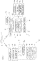
- FIG. 1 is a schematic configuration diagram of a spray vaporization rate prediction device 8 according to one embodiment of the present invention.
- the spray vaporization rate prediction device 8 shown in FIG. 1 predicts the vaporization rate of LNG sprayed into a cargo tank 3 of an LNG carrying vessel 2 by using information collected in on-board information equipment 20 provided to the LNG carrying vessel 2.
- the spray vaporization rate prediction device 8 according to the present embodiment is included in on-land information equipment 5 which is a data center for the LNG carrying vessel 2.
- the spray vaporization rate prediction device 8 may be included in the on-board information equipment 20.
- the spray vaporization rate prediction device 8 is applied to the LNG carrying vessel 2 shown in FIG. 2 , for example.
- the LNG carrying vessel 2 includes a hull 31, and a plurality of cargo tanks 3 mounted to the hull 31 and for storing LNG.
- the hull 31 is provided with a bridge 36 at the rear of the cargo tanks 3.
- the cargo tanks 3 are spherical moss-type tanks.
- the cargo tanks 3 may be membrane tanks or self-supporting prismatic tanks (SPB).
- the LNG carrying vessel 2 is provided with a spray device 7 for cooling the cargo tanks 3.
- the spray device 7 includes spray pumps 71 provided at the bottoms of the respective cargo tanks 3, a collective pipe 73 provided outside the cargo tanks 3, suction pipes 72 connecting the collective pipe 73 and the respective spray pumps 71, spray pipes 74 extending from the collective pipe 73 into the respective cargo tanks 3, and spray nozzles 75 provided at the outlets of the spray pipes 74.
- the spray device 7 performs spray operation of spraying LNG stored in each cargo tank 3, into the cargo tank 3, via the spray pump 71, the suction pipe 72, the collective pipe 73, the spray pipe 74, and the spray nozzle 75.
- spray nozzles 75 having different opening areas are connected to the spray pipe 74, and a switching valve (not shown) for selectively supplying LNG to one or some of the spray nozzles 75 is provided to the spray pipe 74.
- a switching valve (not shown) for selectively supplying LNG to one or some of the spray nozzles 75 is provided to the spray pipe 74.
- the LNG carrying vessel 2 uses gas generated through vaporization of the LNG, as fuel for propulsion.
- the natural gas used as the fuel contains natural boil off gas (NBOG) naturally generated in the cargo tank 3, and spray vaporization gas through vaporization of the LNG sprayed into the cargo tank 3.
- the LNG carrying vessel 2 includes a main engine 35 for driving a screw propeller, and a supply line 33 for guiding the natural gas from the cargo tank 3 to the main engine 35.
- a compressor 34 is provided to the supply line 33.
- the main engine 35 may be any type that obtains motive power through combustion of natural gas.
- the main engine 35 may be a reciprocating engine, a gas turbine engine, a combination of a gas fired boiler and a steam turbine, or the like.
- the reciprocating engine may be a gas mono-fuel combustion engine in which only natural gas is combusted, or may be a dual fuel engine in which one or both of natural gas and fuel oil are combusted.
- the on-board information equipment 20 shown in FIG. 1 is provided in the bridge 36 of the LNG carrying vessel 2.
- the on-board information equipment 20 includes a vessel-side communication device 21, a processing device 22, a storage device 23a, and a display device 24.
- a box denoted by 23a represents the storage device 23a, and information stored in the storage device 23a is shown in this box.
- the processing device 22 includes a processor, a communication interface, a storage unit, and the like (all not shown).
- the processing device 22 performs processing as a tank actual measured data collecting unit 22a by the processor reading and executing programs (tank actual measured data collecting program, etc.) stored in advance in the storage unit.
- the communication interface transmits/receives data to/from various vessel mounted devices such as the spray pumps 71, and receives detection signals from various vessel mounted devices such as a pressure gauge 83, a temperature gauge 84, and a level gauge 85, with use of wireless or wired communication means.
- the pressure gauge 83 detects the pressure in the gas space in the cargo tank 3.
- the temperature gauge 84 detects the temperature (LNG spray temperature) of LNG ejected from the spray nozzle 75.
- the level gauge 85 detects the liquid level which is the liquid surface level of the cargo tank 3.
- the spray pump 71 is provided with a meter for detecting the ejection pressure and the ejection amount thereof, or the ejection pressure and the ejection amount can be calculated from the rotation speed of the spray pump 71 by using a certain correspondence relationship.
- the tank actual measured data collecting unit 22a acquires information from at least the spray pump 71, the pressure gauge 83, the temperature gauge 84, and the level gauge 85, and generates tank actual measured data including at least the ejection pressure and the ejection amount of the spray pump 71, the internal pressure of the cargo tank 3, the LNG spray temperature, the liquid level of the cargo tank 3, and the tank temperature.
- the tank actual measured data collecting unit 22a stores the generated tank actual measured data into the storage device 23a, and outputs the same to the vessel-side communication device 21.
- the vessel-side communication device 21 transmits the tank actual measured data to a land-side communication device 51 of the on-land information equipment 5 via a vessel-land communication system using a communication satellite 4.
- the on-land information equipment 5 is provided with the spray vaporization rate prediction device 8.
- the spray vaporization rate prediction device 8 includes the land-side communication device 51, a processing device 52, an input device 54, a display device 55, and various storage devices 53a to 53d.
- boxes denoted by 53a to 53d represent the storage devices 53a to 53d, and information stored in the storage devices 53a to 53d is shown in the boxes.
- the storage devices 53a to 53d may be formed as separate storage devices, or a plurality of the storage devices may be formed as a single storage device.
- the processing device 52 includes a processor, a communication interface, a storage unit, and the like (all not shown).
- the processing device 22 performs processing as a spray vaporization rate prediction unit 65 and a coefficient calculation unit 66 by the processor reading and executing programs (vaporization rate prediction program, a coefficient calculation program, etc.) stored in advance in the storage unit.
- the communication interface is capable of transmitting/receiving information to/from an external organization 12 via a network 11, with use of wireless or wired communication means.
- one external organization 12 is shown as a representative, and there may be a plurality of or plural kinds of servers of the external organization 12 communicably connected to the processing device 52.
- the input device 54 is means such as a mouse and a keyboard for receiving an input through a user operation.
- the input device 54 outputs information inputted through a user's operation, to the processing device 52.
- the display device 55 is a display device such as a liquid crystal display, and displays, on the screen, information corresponding to display data given from the processing device 52.
- the land-side communication device 51 is capable of mutual communication with the vessel-side communication device 21 mounted to the LNG carrying vessel 2, via the vessel-land communication system using the communication satellite 4.
- the processing device 52 controls the land-side communication device 51 to transmit information about an optimum route described later, to the vessel-side communication device 21, and acquires information such as the tank actual measured data.
- the tank actual measured data is stored in the storage device 53a.
- the processing device 52 stores the tank actual measured data received from the on-board information equipment 20, into the storage device 53a. Transmission of the tank actual measured data from the on-board information equipment 20 to the on-land information equipment 5 may be performed every time the tank actual measured data is generated, or may be performed every predetermined period.
- the tank actual measured data generated in the on-board information equipment 20 may be passed to the on-land information equipment 5 via a storage medium.
- a tank table (freight tank capacity table of cargo tank 3) is stored in the storage device 53b.
- the tank table is data that allows calculation of the liquid capacity for which the attitude of the hull and thermal contraction at the time of cooling of the cargo tank 3 are taken into consideration, on the basis of the liquid temperature in the cargo tank 3, the temperature and the density of the gas space vapor in the cargo tank 3, the trim and the list of the vessel, the liquid level in the cargo tank 3, and the like.
- the tank table is data specific to each cargo tank 3, and is provided from a third-party certification organization.
- the pressure-flow rate characteristics (P-Q graph) of the spray nozzle 75 are stored in the storage device 53c.
- the pressure-flow rate characteristics indicate the relationship between the pressure value and the flow rate value of the spray nozzle 75.
- the pressure-flow rate characteristics are characteristics specific to the spray nozzle 75, and are provided from manufacturer of the spray nozzle 75.
- Data such as prediction formula and a coefficient used or generated when the vaporization rate prediction program and the coefficient calculation program are executed, are stored in the storage device 53d.
- the spray vaporization rate prediction unit 65 reads and uses information stored in the storage devices 53a to 53c as appropriate, to calculate a "spray vaporization rate X0" which represents the ratio of a flow rate Gg of vaporized gas with respect to a spray flow rate G of the LNG sprayed into the target cargo tank 3.
- the spray vaporization rate X0 may be calculated for all the cargo tanks 3 mounted to the LNG carrying vessel 2, or may be calculated for one or a plurality of cargo tanks 3 as a representative for all the cargo tanks 3.
- the flow rate Gg of the gas can be approximated by the following Expression 2 using a vapor quality X.
- Gg a ⁇ X ⁇ G
- the vapor quality X is a state quantity representing the mass fraction of the gas in a saturated state.
- the vapor quality X can be calculated through thermophysical property calculation from the internal pressure of the cargo tank 3 and the saturation temperature of the sprayed LNG.
- a is a coefficient with which the spray vaporization rate X0 is proportional to the vapor quality X.
- the coefficient a also serves to correct the flow rate Gl of the liquid dropping to the liquid layer in the cargo tank 3 without being vaporized with respect to the spray flow rate G.
- such liquid includes, for example, (i) liquid that is not completely vaporized during dropping in the cargo tank 3, thus dropping to the heel, (ii) liquid colliding with or being reflected by the wall surface of the cargo tank 3, thus dropping in a liquid state to the heel, and (iii) a liquid film formed by concentration of the spray at a part where the temperature is locally reduced on the wall surface of the cargo tank 3, thus dropping to the heel.
- the coefficient a is a value specific to the cargo tank 3, determined by various factors such as the shape of the cargo tank 3 and the position and the ejection characteristics of the spray nozzle 75.
- the coefficient calculation unit 66 calculates the coefficient a using Expression 4 and the tank actual measured data, and stores the coefficient a into the storage device 53d.
- the spray flow rate G of the LNG to be substituted into Expression 4 can be calculated from the pressure-flow rate characteristics representing the relationship between the pressure value and the flow rate value of the spray nozzle 75.
- the pressure value of the spray nozzle 75 is substantially equal to the difference between the ejection pressure of the spray pump 71 and the internal pressure of the cargo tank 3 included in the tank actual measured data.
- the flow rate Gl of the liquid to be substituted into Expression 4 can be calculated for each cargo tank 3 by considering the mass change amount of the LNG in the heel calculated from the tank table and the liquid level change amount in the cargo tank 3, the amount of natural boil off gas generated from the heel, and the ejection amount of the spray pump 71 regarding the cargo tank 3 that actuates the spray pump 71.
- the change in the liquid level of the cargo tank 3 can be calculated from the liquid level included in the tank actual measured data.
- the vapor quality X to be substituted into Expression 4 can be calculated from the LNG temperature and the pressure in the cargo tank 3.
- the LNG temperature and the pressure in the cargo tank 3 are both included in the tank actual measured data.
- the spray vaporization rate prediction unit 65 predicts the flow rate Gl of the liquid and the flow rate Gg of the gas for optional date and time in the voyage, using the coefficient a calculated in advance and the prediction formulas shown by Expression 2 and Expression 3.
- the coefficient a to be multiplied with the vapor quality X is calculated in advance on the basis of the actual measured data in the LNG carrying vessel 2, and then the spray vaporization rate X0 for optional date and time in the voyage is predicted as a value obtained by multiplying the vapor quality X for the optional date and time by the coefficient a.
- the spray vaporization rate prediction device 8 includes the storage device 53d storing the coefficient a which is calculated in advance on the basis of the actual measured data in the LNG carrying vessel 2 and is to be multiplied with the vapor quality X in the cargo tank 3 in calculating the spray vaporization rate X0 from the vapor quality X, and the processing device 52 including the spray vaporization rate prediction unit 65 for predicting the spray vaporization rate X0 for optional date and time in the voyage as a value obtained by multiplying the vapor quality X for the optional date and time by the coefficient a.
- the above spray vaporization rate prediction method and device 8 can accurately predict the vaporization rate of the LNG sprayed into the cargo tank 3 of the LNG carrying vessel 2, as compared to the case of assuming that the sprayed LNG is all vaporized. That is, the spray vaporization rate X0 is closer to the actual value than the vapor quality X which is a theoretical spray vaporization rate.
- the spray vaporization rate X0 predicted as described above values close to the actual values can be estimated for the BOG generation amount, the cargo tank pressure, the LNG temperature, the liquid level, the tank temperature, and the like.
- the processing device 52 further includes the coefficient calculation unit 66 which estimates the flow rate G1 of the liquid dropping to the liquid layer in the cargo tank 3 without being vaporized with respect to the spray flow rate G of the LNG, on the basis of the change amount in the liquid layer in the cargo tank 3 and the ejection amount of the spray pump 71 which pumps up the LNG to be sprayed, from the cargo tank 3, and calculates the coefficient a on the basis of the ratio of a flow rate obtained by subtracting the flow rate Gl of the dropping liquid from the spray flow rate G, with respect to the spray flow rate G.
- the coefficient calculation unit 66 stores the coefficient a into the storage device 53d.
- the flow rate Gl of the liquid dropping to the liquid layer in the cargo tank 3 without being vaporized with respect to the spray flow rate G of the LNG is estimated on the basis of the change amount in the liquid layer in the cargo tank 3 and the ejection amount of the spray pump 71 which pumps up the LNG to be sprayed, from the cargo tank 3, and the coefficient a is calculated on the basis of the ratio of a flow rate (i.e., the flow rate Gg of the gas) obtained by subtracting the flow rate Gl of the dropping liquid from the spray flow rate G, with respect to the spray flow rate G.
- a flow rate i.e., the flow rate Gg of the gas
- the spray flow rate G of the LNG is considered separately as the flow rate Gg of the gas and the flow rate Gl of the liquid not vaporized, whereby the cooling effect for the cargo tank 3 by spray operation, the amount of BOG generated in the cargo tank 3, the heel amount in the cargo tank 3, and the like can be more accurately estimated.
- the entire amount of the ejection amount of the spray pump 71 is ejected from the spray nozzle 7, and such a phenomenon in which a part of the LNG ejected from the spray pump 71 returns to the heel in the cargo tank 3 through a bypass line without being ejected from the spray nozzle 75, is not taken into consideration.
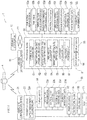
- the operation assistance system 1 shown in FIG. 3 includes the entire spray vaporization rate prediction device 8 described above.
- the same elements as those of the spray vaporization rate prediction device 8 described above are denoted by the same reference characters, and the same description therefor is omitted.
- the operation assistance system 1 includes the on-land information equipment 5, and the on-board information equipment 20 provided to the LNG carrying vessel 2.
- the on-board information equipment 20 includes the vessel-side communication device 21, the processing device 22, storage devices 23a to 23d, and the display device 24.
- the vessel-side communication device 21 the processing device 22, storage devices 23a to 23d, and the display device 24.
- boxes denoted by 23a to 23d represent the storage devices 23a to 23d, and information stored in the storage devices 23a to 23d is shown in the boxes.
- Data such as nautical chart data to be used for a voyage is stored in advance in the storage device 23b.
- Voyage actual measured data is stored in the storage device 23c of the on-board information equipment 20.
- the processing device 22 stores nautical chart data and the like inputted to the processing device 22 via an input device (not shown), into the storage device 23b.
- the processing device 22 stores the voyage actual measured data such as the vessel speed and position information (latitude and longitude) measured by various sensors (not shown), into the storage device 23c.
- the processing device 22 outputs the voyage actual measured data stored in the storage device 23c to the vessel-side communication device 21, and displays the same on the display device 24.
- the vessel-side communication device 21 transmits the voyage actual measured data outputted from the processing device 22, to the land-side communication device 51 via the communication satellite 4. In addition, the vessel-side communication device 21 receives operation management data including an optimum ballast route described later, from the land-side communication device 51.
- the processing device 22 stores the operation management data received by the vessel-side communication device 21, into the storage device 23d, and displays the same on the display device 24.
- the on-land information equipment 5 includes the land-side communication device 51, the processing device 52, the input device 54, the display device 55, and various storage devices 53a to 53j.
- boxes denoted by 53a to 53j represent the storage devices 53a to 53j, and information stored in the storage devices 53a to 53j is shown in the boxes.
- the storage devices 53a to 53j may be formed as separate storage devices, or a plurality of the storage devices may be formed as a single storage device.
- Nautical chart data of a marine area through which the LNG carrying vessel 2 passes, and a plurality of recommended routes, are stored in advance in the storage device 53e.
- the individual vessel performance data specific to the LNG carrying vessel 2 is stored in advance in the storage device 53f.
- the individual vessel performance data may be, for example, a hull performance model.
- the hull performance model is a numerical model or a simulation model for calculating characteristics of the hull 31 in calm water and response characteristics (resistance increase characteristics and hull movement characteristics) of the hull 31 in waves.
- the hull performance model includes performance obtained by adding influence of disturbance in the actual marine area such as wind, wind wave, and swell to the performance of the hull 31 in calm water.
- Voyage schedule data is stored in advance in the storage device 53g.
- the voyage schedule data includes a loading port and a discharging port, date and time of departure and date and time of arrival in a laden voyage from the loading port to the discharging port, date and time of departure and date and time of arrival in a ballast voyage from the discharging port to the loading port, and the like.
- Voyage actual measured data is stored in the storage device 53h.
- the processing device 52 acquires the voyage actual measured data received by the land-side communication device 51, and stores the voyage actual measured data into the storage device 53h.
- Marine weather data of a marine area through which the LNG carrying vessel 2 passes is stored in the storage device 53i.
- the processing device 52 acquires the marine weather data from the external organization 12 such as the Meteorological Agency or National Oceanic and Atmospheric Administration (NOAA) via the network 11, and stores the acquired marine weather data into the storage device 53i.
- the external organization 12 such as the Meteorological Agency or National Oceanic and Atmospheric Administration (NOAA)
- Operation management data is stored in the storage device 53j.
- the processing device 52 performs calculation using various data stored in the storage devices 53a to 53i, to generate the operation management data.
- the operation management data may include the optimum route from the present location to the discharging port, and the optimum ballast route from the discharging port to the loading port.
- the processing device 52 stores the generated operation management data into the storage device 53j, and outputs the same to the land-side communication device 51.
- the land-side communication device 51 transmits the operation management data outputted from the processing device 52, to the vessel-side communication device 21 via the communication satellite 4.
- the processing device 52 has functions as a route creating unit 61, a first vaporization gas amount estimation unit 62, a second vaporization gas amount estimation unit 63, a heel amount calculation unit 64, a spray vaporization rate prediction unit 65, a coefficient calculation unit 66, and a tank state estimation unit 67.
- the processing device 52 performs processing as these function units by the processor reading and executing various programs stored in advance in the storage unit.
- the route creating unit 61 predicts the marine weather that the LNG carrying vessel 2 will experience during the voyage, from the marine weather data stored in the storage device 53i, calculates vessel speed performance, hull movement, the amount of fuel consumption, and the like in the predicted marine weather on the basis of the individual vessel performance data stored in the storage device 53f, and selects an optimum route from a plurality of given recommended routes.
- the optimum route is an optimum route that optimizes predetermined evaluation indices such as a safest route, a shortest time route, a minimum fuel consumption route, and a most economical route, and in the present embodiment, the optimum route is a minimum fuel consumption route with a fixed voyage period.
- the route creating unit 61 may calculate the optimum route from the present location to the discharging port, and the optimum ballast route from the discharging port to the loading port.
- the route creating unit 61 calculates an optimum ballast route from the present location to the loading port.
- the tank state estimation unit 67 estimates at least one of the BOG generation amount, the pressure, the LNG temperature, the liquid level, and the tank temperature in the cargo tank 3 for optional date and time.
- the tank state estimation unit 67 calculates an estimation value for at least one of the BOG generation amount, the pressure, the LNG temperature, the liquid level, and the tank temperature in the cargo tank 3 on the basis of the individual vessel performance data stored in the storage device 53f, the marine weather data stored in the storage device 53i, the predicted value of the spray vaporization rate X0 calculated by the spray vaporization rate prediction unit 65, the tank table stored in the storage device 53b, the tank actual measured data stored in the storage device 53a, and the like.
- the values representing the state of the cargo tank 3 such as the BOG generation amount, the pressure, the LNG temperature, the liquid level, and the tank temperature in the cargo tank 3 can be calculated through calculation on the basis of the conservation law of energy and the flow rate of the LNG, using the spray vaporization rate X0, the boil off rate, the heat transfer amount, and the like, while the initial status quantities of the cargo tank 3, the external conditions of the cargo tank 3, the specifications of the cargo tank 3, and the like are set as input conditions.
- the initial status quantities of the cargo tank 3 include the LNG temperature, the LNG pressure, the LNG composition, and the like in the cargo tank 3.
- the external conditions of the cargo tank 3 include the outside temperature, the insolation amount, the atmosphere diffusion amount, the atmospheric pressure, the seawater temperature, the wind direction, the wind speed, the BOG extraction amount, the vessel speed, the vessel direction, and the like.
- the specifications of the cargo tank 3 include the specifications of the cargo tank 3 and pipes, such as shape data, material physical property data, and thermophysical property data.
- the tank state estimation unit 67 may cooperate with the route creating unit 61. That is, the route creating unit 61 may search for an optimum ballast route while including, in the evaluation indices, at least one of the BOG generation amount, the pressure, the LNG temperature, the liquid level, and the tank temperature estimated by the tank state estimation unit 67.
- the first vaporization gas amount estimation unit 62 estimates a total amount Qn of the natural boil off gas (NBOG) to be generated from the LNG left in the cargo tank 3 during a voyage through the optimum ballast route.
- the first vaporization gas amount estimation unit 62 calculates the NBOG generation amount (the amount of natural boil off gas) per unit time when the LNG carrying vessel 2 is on a voyage through the optimum ballast route, on the basis of the individual vessel performance data stored in the storage device 53f, the marine weather data stored in the storage device 53i, and the predicted value of the spray vaporization rate calculated by the spray vaporization rate prediction unit 65.
- the NBOG generation amount varies by the influence of the difference between the outside temperature and the internal temperature of the cargo tank 3, the pressure in the cargo tank 3, oscillation of the liquid surface, and the like.
- the spray vaporization rate X0 influences the pressure, the LNG temperature, the liquid level, and the tank temperature in the cargo tank 3, and as a result, also influences the BOG generation amount.
- the NBOG generation amount per unit time may be calculated on the basis of heat entering the LNG in the cargo tank 3 which is calculated from the outside condition (outside temperature, insolation amount, atmosphere diffusion amount, wind direction/wind speed, etc.) varying every moment, the vessel speed, the vessel direction, the seawater temperature, the LNG temperature, oscillation of the LNG, and the like.
- the first vaporization gas amount estimation unit 62 estimates the total amount Qn of the NBOG by summing up the NBOG generation amount per unit time over the ballast voyage period.
- the unit time for the NBOG generation amount may be one hour, twelve hours (half day), or twenty-four hours (one day).
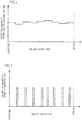
- the second vaporization gas amount estimation unit 63 estimates a total amount Qs of the spray vaporization gas to be generated through vaporization by spray operation during a voyage through the optimum ballast route, on the basis of the marine weather data stored in the storage device 53i and the predicted value of the spray vaporization rate X0 calculated by the spray vaporization rate prediction unit 65. Specifically, as shown in FIG.
- the second vaporization gas amount estimation unit 63 determines spray operation times on the basis of the marine weather data, calculates the spray vaporization gas generation amount for each spray operation on the basis of the spray vaporization rate X0 calculated by the spray vaporization rate prediction unit 65, and sums up the spray vaporization gas generation amounts over the ballast voyage period, thereby estimating the total amount Qs of the spray vaporization gas.
- the spray vaporization gas generation amounts in the respective spray operations are constant. However, the spray vaporization gas generation amount may differ among the spray operations.
- the second vaporization gas amount estimation unit 63 determines the spray operation times so that, in a ballast voyage from the discharging port to the loading port, the tank temperature at a reference point (in the case of a moss-type tank, a point on the equator) of the cargo tank 3 is kept under a predetermined temperature (e.g., LNG temperature + 50°C; about -110°C) at the time of arrival at the loading port.
- a time schedule may be determined so that spray operation will be started when the temperature at the reference point in the cargo tank 3 rises to the predetermined temperature.
- a time schedule may be determined so that spray operation will be started at such time intervals as to assuredly prevent the temperature at the reference point in the cargo tank 3 from reaching the predetermined temperature.
- the calculated necessary heel amount Qh is outputted from the processing device 52 to the land-side communication device 51, and the land-side communication device 51 transmits the necessary heel amount Qh to the vessel-side communication device 21.
- the vaporization rate X0 of the LNG sprayed into the cargo tank has been taken into consideration, so that change in the liquid level of the cargo tank 3 during a ballast voyage is reflected more accurately. Then, determining the heel amount at the discharging port before the ballast voyage on the basis of the above necessary heel amount Qh can optimize (minimize) the heel amount at the discharging port while avoiding such an event in which the heel amount at the loading port becomes excessive or the heel amount becomes deficient during the ballast voyage.
- the operation assistance system 1 is an operation assistance system for the LNG carrying vessel 2 (an example of a liquefied gas carrying vessel) including the cargo tank 3 for storing LNG and the spray device 7 for performing spray operation of spraying the LNG into the cargo tank 3, the operation assistance system using gas generated through vaporization of the LNG as fuel for propulsion, and the operation assistance system 1 includes the communication device 51 communicable with the LNG carrying vessel 2, the processing device 52, and the storage devices 53a to 53j.
- the spray vaporization rate X0 representing the ratio of the flow rate Gg of gas vaporized in the cargo tank 3 with respect to the spray flow rate G of the LNG is approximated using the vapor quality X in the cargo tank 3 which is corrected by the coefficient a.
- the coefficient a also corrects the flow rate Gl of liquid dropping to the liquid layer in the cargo tank without being vaporized with respect to the spray flow rate G.
- the storage device 52d stores the coefficient a which is calculated in advance on the basis of the actual measured data acquired from the LNG carrying vessel 2 and is to be multiplied with the vapor quality X in the cargo tank 3 in calculating the spray vaporization rate X0 from the vapor quality X.
- the processing device 52 includes the spray vaporization rate prediction unit 65 for predicting the spray vaporization rate X0 for optional date and time in a voyage as a value obtained by multiplying the vapor quality X for the optional date and time by the coefficient a, and a tank state estimation unit 67 for estimating at least one of the vaporization gas generation amount, the pressure, the LNG temperature, the liquid level, and the tank temperature in the cargo tank 3 for the optional date and time, using the predicted spray vaporization rate X0.
- the operation assistance method includes: calculating, in advance, the coefficient a to be multiplied with the vapor quality X in the cargo tank 3 in calculating the spray vaporization rate X0 from the vapor quality X, on the basis of the actual measured data in the LNG carrying vessel 2; predicting the spray vaporization rate X0 for optional date and time in a voyage as a value obtained by multiplying the vapor quality X for the optional date and time by the coefficient a; and estimating at least one of the vaporization gas generation amount, the pressure, the LNG temperature, and the liquid level in the cargo tank 3 for the optional date and time, using the predicted spray vaporization rate X0.
- the vaporization rate X0 of the LNG sprayed into the cargo tank 3 of the LNG carrying vessel 2 can be accurately predicted, and values close to the actual values can be estimated for the BOG generation amount, the pressure, the LNG temperature, the liquid level, the tank temperature, and the like in the cargo tank 3.
- the storage device includes: the first storage unit (storage device 53d) for storing the coefficient a which is calculated in advance on the basis of the actual measured data acquired from the LNG carrying vessel 2 and is to be multiplied with the vapor quality X in the cargo tank 3 in calculating the spray vaporization rate X0 from the vapor quality X; the second storage unit (storage device 53f) for storing the individual vessel performance data of the LNG carrying vessel 2; and the third storage unit (storage device 53i) for storing the marine weather data of a marine area through which the LNG carrying vessel 2 passes.
- the first storage unit storage device 53d
- the coefficient a which is calculated in advance on the basis of the actual measured data acquired from the LNG carrying vessel 2 and is to be multiplied with the vapor quality X in the cargo tank 3 in calculating the spray vaporization rate X0 from the vapor quality X
- the second storage unit storage device 53f
- the third storage unit storage device 53i
- the processing device 52 includes: the spray vaporization rate prediction unit 65 for predicting the spray vaporization rate X0 for optional date and time in a voyage as a value obtained by multiplying the vapor quality X for the optional date and time by the coefficient a; the route creating unit 61 for creating an optimum ballast route that optimizes a predetermined evaluation index, on the basis of the individual vessel performance data and the marine weather data; the first vaporization gas amount estimation unit 62 for estimating the total amount Qn of natural boil off gas to be generated from the LNG left in the cargo tank 3 during a voyage through the optimum ballast route, on the basis of the individual vessel performance data, the marine weather data, and the spray vaporization rate; the second vaporization gas amount estimation unit 63 for estimating the total amount Qs of spray vaporization gas to be generated through vaporization by spray operation during the voyage through the optimum ballast route, on the basis of the individual vessel performance data, the marine weather data, and the spray vaporization rate; and the heel amount calculation unit 64 for calculating the
- the operation assistance method for the LNG carrying vessel 2 includes: calculating, in advance, the coefficient a to be multiplied with the vapor quality X in the cargo tank 3 in calculating the spray vaporization rate X0 from the vapor quality X, on the basis of the actual measured data in the LNG carrying vessel 2; predicting the spray vaporization rate X0 for optional date and time in a voyage as a value obtained by multiplying the vapor quality X for the optional date and time by the coefficient a; creating an optimum ballast route that optimizes a predetermined evaluation index, on the basis of the individual vessel performance data of the LNG carrying vessel 2 and the marine weather data; estimating the total amount Qn of natural boil off gas to be generated from the LNG left in the cargo tank 3 during a voyage through the optimum ballast route, on the basis of the individual vessel performance data, the marine weather data, and the spray vaporization rate X0; estimating the total amount Qs of spray vaporization gas to be generated through vaporization by spray operation during the voyage through
- the necessary heel amount Qh is calculated by adding the total amount Qn and the total amount Qs.
- the necessary heel amount Qh can be accurately calculated.
- the calculated necessary heel amount Qh may be transmitted to the LNG carrying vessel 2 during a laden voyage. Accordingly, a crew of the LNG carrying vessel 2 can determine the amount of LNG that should be unloaded, so that this LNG amount is maximized, by referring to the necessary heel amount Qh at the discharging port.
Landscapes
- Engineering & Computer Science (AREA)
- Mechanical Engineering (AREA)
- Chemical & Material Sciences (AREA)
- Combustion & Propulsion (AREA)
- Ocean & Marine Engineering (AREA)
- Radar, Positioning & Navigation (AREA)
- Remote Sensing (AREA)
- General Engineering & Computer Science (AREA)
- Filling Or Discharging Of Gas Storage Vessels (AREA)
Abstract
Description
- The present invention relates to technology for, in a liquefied gas carrying vessel for carrying liquefied gas such as liquefied natural gas (LNG), predicting the vaporization rate of the liquefied gas sprayed into a cargo tank, and to operation assistance technology using the prediction technology.
- Conventionally, in a liquefied gas carrying vessel for carrying liquefied gas such as LNG, on a ballast voyage from a discharging port to a loading port, liquefied gas of a predetermined heel amount (remaining liquid amount) is left in a cargo tank, and the liquefied gas is pumped up by a spray pump and sprayed into the cargo tank during the ballast voyage, whereby increase in the temperature of the cargo tank is suppressed.
- In some of such liquefied gas carrying vessels, gas (BOG) generated through vaporization of laden liquefied gas in a cargo tank is utilized for vessel propulsion energy, i.e., fuel for a main engine.
- In such a liquefied gas carrying vessel that utilizes liquefied gas in a cargo tank for a cooling refrigerant and voyage fuel during a ballast voyage as described above, the heel amount before leaving at a discharging port is generally the sum of a heel amount at a loading port, a fuel consumption amount calculated from a ballast voyage distance and a planned vessel speed, and a margin considering worsening of the marine weather during the voyage and the like. A less heel amount at the discharging port leads to a larger trade amount of liquefied gas, and thus is economical.
- PTL 1 proposes a voyage planning system that takes change in the amount of BOG generation due to the weather (i.e., due to the amount of heat input to the cargo tank) into consideration, in making a voyage plan of an LNG carrying vessel as described above. In this voyage planning system, the daily BOG generation amount is calculated on the basis of daily weather information, and optimum daily vessel speed and vessel position are calculated from the daily BOG generation amount, thereby preventing occurrence of deficiency/excess of propulsion energy.
- PTL 1: Japanese Laid-Open Patent Publication No.
H08-318899 - In calculation for the fuel consumption amount included in the heel amount at the discharging port described above, in general, the BOG generation amount, the pressure, the liquefied gas temperature, the liquid level, the tank temperature, and the like in the cargo tank are estimated under the assumption that liquefied gas sprayed into the cargo tank during a ballast voyage is all vaporized, i.e., under the assumption that the vaporization rate is 1. However, in actuality, while a majority of droplets of liquefied gas sprayed into the cargo tank are vaporized in the cargo tank, some of the droplets are not completely vaporized, ending up dropping to the liquid layer of the heel. In the case where the liquefied gas is LNG, the dropped droplet has a high proportion of heavy components such as ethane and propane because most of a methane component exits from the LNG. Therefore, as spraying is continued, heavy components in the liquid of the heel increase, i.e., the composition of the liquid changes. Thus, the BOG generation amount, the pressure, the liquefied gas temperature, the liquid level, the tank temperature, and the like in the cargo tank estimated as described above can deviate from the actual values. Using the heel amount at the discharging port which includes the fuel consumption amount calculated on the basis of the estimated values deviating from the actual values as described above can cause an event in which the heel amount at the loading port becomes excessive or the heel amount becomes deficient during the ballast voyage, in an actual operation. In addition, there is a possibility that the tank temperature cannot be maintained as predicted.
- In order to solve such a problem, technology for more accurately predicting the vaporization rate of liquefied gas sprayed into the cargo tank is needed. That is, if the vaporization rate of the liquefied gas sprayed into the cargo tank can be predicted with high accuracy, values close to the actual values can be estimated for the BOG generation amount, the cargo tank pressure, the liquefied gas temperature, the liquid level, the tank temperature, and the like. Therefore, it is possible to more accurately predict change in the liquid level during a ballast voyage. This is expected to contribute to optimization (minimization) of the heel amount at the discharging port.
- The present invention has been made in view of the above circumstances, and an object of the present invention is to provide technology for accurately predicting the vaporization rate of liquefied gas sprayed into a cargo tank of a liquefied gas carrying vessel.
- A spray vaporization rate prediction method according to one aspect of the present invention is a spray vaporization rate prediction method for predicting a spray vaporization rate in a liquefied gas carrying vessel including a cargo tank for storing liquefied gas, and a spray device for performing spray operation of spraying the liquefied gas into the cargo tank, the liquefied gas carrying vessel using gas generated through vaporization of the liquefied gas as fuel for propulsion, the spray vaporization rate representing a ratio of a flow rate of gas vaporized in the cargo tank with respect to a spray flow rate of the liquefied gas, the method including: calculating, in advance, a coefficient to be multiplied with a vapor quality in the cargo tank in calculating the spray vaporization rate from the vapor quality, on the basis of actual measured data in the liquefied gas carrying vessel; and predicting the spray vaporization rate for optional date and time in a voyage as a value obtained by multiplying the vapor quality for the optional date and time by the coefficient. Here, the vapor quality can be calculated from the pressure in the cargo tank and the saturation temperature of the liquefied gas.
- The above spray vaporization rate prediction method may further include: estimating a flow rate of liquid dropping to a liquid layer in the cargo tank without being vaporized with respect to the spray flow rate of the liquefied gas, on the basis of an amount of change in the liquid layer in the cargo tank and an ejection amount of a spray pump for pumping up the liquefied gas to be sprayed, from the cargo tank; and calculating the coefficient on the basis of a ratio of a flow rate obtained by subtracting the flow rate of the dropping liquid from the spray flow rate, with respect to the spray flow rate.
- The above spray vaporization rate prediction method can accurately predict the vaporization rate of the liquefied gas sprayed into the cargo tank of the liquefied gas carrying vessel, as compared to the case of assuming that the sprayed liquefied gas is all vaporized. In addition, by using the spray vaporization rate predicted as described above, values close to the actual values can be estimated for the BOG generation amount, the pressure, the liquefied gas temperature, the liquid level, the tank temperature, and the like in the cargo tank.
- A spray vaporization rate prediction device according to another aspect of the present invention is a spray vaporization rate prediction device for predicting a spray vaporization rate in a liquefied gas carrying vessel including a cargo tank for storing liquefied gas, and a spray device for performing spray operation of spraying the liquefied gas into the cargo tank, the liquefied gas carrying vessel using gas generated through vaporization of the liquefied gas as fuel for propulsion, the spray vaporization rate representing a ratio of a flow rate of gas vaporized in the cargo tank with respect to a spray flow rate of the liquefied gas, the spray vaporization rate prediction device including: a storage device configured to store a coefficient which is calculated in advance on the basis of actual measured data in the liquefied gas carrying vessel and is to be multiplied with a vapor quality in the cargo tank in calculating the spray vaporization rate from the vapor quality; and a processing device including a spray vaporization rate prediction unit configured to predict the spray vaporization rate for optional date and time in a voyage as a value obtained by multiplying the vapor quality for the optional date and time by the coefficient.
- In the above spray vaporization rate prediction device, the processing device may further include a coefficient calculation unit configured to: estimate a flow rate of liquid dropping to a liquid layer in the cargo tank without being vaporized with respect to the spray flow rate of the liquefied gas, on the basis of an amount of change in the liquid layer in the cargo tank and an ejection amount of a spray pump for pumping up the liquefied gas to be sprayed, from the cargo tank; calculate the coefficient on the basis of a ratio of a flow rate obtained by subtracting the flow rate of the dropping liquid from the spray flow rate, with respect to the spray flow rate; and store the coefficient into the storage device.
- The above spray vaporization rate prediction device can accurately predict the vaporization rate of the liquefied gas sprayed into the cargo tank of the liquefied gas carrying vessel, as compared to the case of assuming that the sprayed liquefied gas is all vaporized. In addition, by using the spray vaporization rate predicted as described above, values close to the actual values can be estimated for the BOG generation amount, the pressure, the liquefied gas temperature, the liquid level, the tank temperature, and the like in the cargo tank.
- An operation assistance method for a liquefied gas carrying vessel according to another aspect of the present invention is an operation assistance method for a liquefied gas carrying vessel including a cargo tank for storing liquefied gas, and a spray device for performing spray operation of spraying the liquefied gas into the cargo tank, the liquefied gas carrying vessel using gas generated through vaporization of the liquefied gas as fuel for propulsion, the method including: calculating, in advance, a coefficient to be multiplied with a vapor quality in the cargo tank in calculating a spray vaporization rate from the vapor quality, on the basis of actual measured data in the liquefied gas carrying vessel, the spray vaporization rate representing a ratio of a flow rate of gas vaporized in the cargo tank with respect to a spray flow rate of the liquefied gas; predicting the spray vaporization rate for optional date and time in a voyage as a value obtained by multiplying the vapor quality for the optional date and time by the coefficient; and estimating at least one of a vaporization gas generation amount, a pressure, a liquefied gas temperature, a liquid level, and a tank temperature in the cargo tank for the optional date and time, using the predicted spray vaporization rate.
- In the above operation assistance method for the liquefied gas carrying vessel, as compared to the case of assuming that the sprayed liquefied gas is all vaporized, the vaporization rate of the liquefied gas sprayed into the cargo tank of the liquefied gas carrying vessel can be accurately predicted, and values close to the actual values can be estimated for the BOG generation amount, the cargo tank pressure, the liquefied gas temperature, the liquid level, the tank temperature, and the like.
- An operation assistance method for a liquefied gas carrying vessel according to another aspect of the present invention is an operation assistance method for a liquefied gas carrying vessel including a cargo tank for storing liquefied gas, and a spray device for performing spray operation of spraying the liquefied gas into the cargo tank, the liquefied gas carrying vessel using gas generated through vaporization of the liquefied gas as fuel for propulsion, the method including: calculating, in advance, a coefficient to be multiplied with a vapor quality in the cargo tank in calculating a spray vaporization rate from the vapor quality, on the basis of actual measured data in the liquefied gas carrying vessel, the spray vaporization rate representing a ratio of a flow rate of gas vaporized in the cargo tank with respect to a spray flow rate of the liquefied gas; predicting the spray vaporization rate for optional date and time in a voyage as a value obtained by multiplying the vapor quality for the optional date and time by the coefficient; creating an optimum ballast route that optimizes a predetermined evaluation index, on the basis of individual vessel performance data of the liquefied gas carrying vessel and marine weather data; estimating a total amount of natural boil off gas to be generated from the liquefied gas left in the cargo tank during a voyage through the optimum ballast route, on the basis of the individual vessel performance data, the marine weather data, and the spray vaporization rate; estimating a total amount of spray vaporization gas to be generated through vaporization by the spray operation during the voyage through the optimum ballast route, on the basis of the individual vessel performance data, the marine weather data, and the spray vaporization rate; and calculating a necessary heel amount before a ballast voyage by adding the estimated total amount of the natural boil off gas and the estimated total amount of the spray vaporization gas.
- In the above operation assistance method for the liquefied gas carrying vessel, as compared to the case of assuming that the sprayed liquefied gas is all vaporized, the vaporization rate of the liquefied gas sprayed into the cargo tank of the liquefied gas carrying vessel can be accurately predicted, and a value close to the actual value can be estimated for the necessary heel amount. Thus, the heel amount before leaving at a discharging port is optimized (minimized), whereby the trade amount of liquefied gas can be optimized (maximized).
- Each of the above operation assistance methods for the liquefied gas carrying vessel may further include: estimating a flow rate of liquid dropping in a liquid state to a liquid layer in the cargo tank with respect to the spray flow rate, on the basis of an amount of change in the liquid layer in the cargo tank and an ejection amount of a spray pump for pumping up the liquefied gas to be sprayed, from the cargo tank; and calculating the coefficient on the basis of a ratio of a flow rate obtained by subtracting the flow rate of the dropping liquid from the spray flow rate, with respect to the spray flow rate.
- An operation assistance system for a liquefied gas carrying vessel according to another aspect of the present invention is an operation assistance system for a liquefied gas carrying vessel including a cargo tank for storing liquefied gas, and a spray device for performing spray operation of spraying the liquefied gas into the cargo tank, the liquefied gas carrying vessel using gas generated through vaporization of the liquefied gas as fuel for propulsion, the operation assistance system including: a communication device communicable with the liquefied gas carrying vessel; a processing device; and a storage device. The storage device stores a coefficient which is calculated in advance on the basis of actual measured data acquired from the liquefied gas carrying vessel and is to be multiplied with a vapor quality in the cargo tank in calculating a spray vaporization rate from the vapor quality, the spray vaporization rate representing a ratio of a flow rate of gas vaporized in the cargo tank with respect to a spray flow rate of the liquefied gas. The processing device includes a spray vaporization rate prediction unit configured to predict the spray vaporization rate for optional date and time in a voyage as a value obtained by multiplying the vapor quality for the optional date and time by the coefficient, and a tank state estimation unit configured to estimate at least one of a vaporization gas generation amount, a pressure, a liquefied gas temperature, a liquid level, and a tank temperature in the cargo tank for the optional date and time, using the predicted spray vaporization rate.
- In the above operation assistance system for the liquefied gas carrying vessel, as compared to the case of assuming that the sprayed liquefied gas is all vaporized, the vaporization rate of the liquefied gas sprayed into the cargo tank of the liquefied gas carrying vessel can be accurately predicted, and values close to the actual values can be estimated for the BOG generation amount, the pressure, the liquefied gas temperature, the liquid level, the tank temperature, and the like in the cargo tank.
- An operation assistance system for a liquefied gas carrying vessel according to another aspect of the present invention is an operation assistance system for a liquefied gas carrying vessel including a cargo tank for storing liquefied gas, and a spray device for performing spray operation of spraying the liquefied gas into the cargo tank, the liquefied gas carrying vessel using gas generated through vaporization of the liquefied gas as fuel for propulsion, the operation assistance system including: a communication device communicable with the liquefied gas carrying vessel; a processing device; and a storage device. The storage device includes: a first storage unit configured to store a coefficient which is calculated in advance on the basis of actual measured data acquired from the liquefied gas carrying vessel and is to be multiplied with a vapor quality in the cargo tank in calculating a spray vaporization rate from the vapor quality, the spray vaporization rate representing a ratio of a flow rate of gas vaporized in the cargo tank with respect to a spray flow rate of the liquefied gas; a second storage unit configured to store individual vessel performance data of the liquefied gas carrying vessel; and a third storage unit configured to store marine weather data of a marine area through which the liquefied gas carrying vessel passes. The processing device includes: a spray vaporization rate prediction unit configured to predict the spray vaporization rate for optional date and time in a voyage as a value obtained by multiplying the vapor quality for the optional date and time by the coefficient; a route creating unit configured to create an optimum ballast route that optimizes a predetermined evaluation index, on the basis of the individual vessel performance data and marine weather data; a first vaporization gas amount estimation unit configured to estimate a total amount of natural boil off gas to be generated from the liquefied gas left in the cargo tank during a voyage through the optimum ballast route, on the basis of the individual vessel performance data, the marine weather data, and the spray vaporization rate; a second vaporization gas amount estimation unit configured to estimate a total amount of spray vaporization gas to be generated through vaporization by the spray operation during the voyage through the optimum ballast route, on the basis of the individual vessel performance data, the marine weather data, and the spray vaporization rate; and a heel amount calculation unit configured to calculate a necessary heel amount before a ballast voyage or during a ballast voyage by adding the estimated total amount of the natural boil off gas and the estimated total amount of the spray vaporization gas.
- In the above operation assistance system for the liquefied gas carrying vessel, as compared to the case of assuming that the sprayed liquefied gas is all vaporized, the vaporization rate of the liquefied gas sprayed into the cargo tank of the liquefied gas carrying vessel can be accurately predicted, and a value close to the actual value can be estimated for the necessary heel amount. Thus, the heel amount before leaving at a discharging port is optimized (minimized), whereby the trade amount of liquefied gas can be optimized (maximized).
- In each of the above operation assistance systems for the liquefied gas carrying vessel, the processing device may further include a coefficient calculation unit configured to: estimate a flow rate of liquid dropping to a liquid layer in the cargo tank without being vaporized with respect to the spray flow rate of the liquefied gas, on the basis of an amount of change in the liquid layer in the cargo tank and an ejection amount of a spray pump for pumping up the liquefied gas to be sprayed, from the cargo tank; calculate the coefficient on the basis of a ratio of a flow rate obtained by subtracting the flow rate of the dropping liquid from the spray flow rate, with respect to the spray flow rate; and store the coefficient into the storage device.
- The present invention can provide technology for accurately predicting the vaporization rate of liquefied gas sprayed into a cargo tank of a liquefied gas carrying vessel.
-
-
FIG. 1 is a schematic configuration diagram of a spray vaporization rate prediction device according to one embodiment of the present invention. -
FIG. 2 schematically shows the entire structure of an LNG carrying vessel. -
FIG. 3 is a schematic configuration diagram of an operation assistance system according to the embodiment of the present invention. -
FIG. 4 is a graph showing change, over time, of the generation amount of natural boil off gas per unit time during a ballast voyage, as predicted. -
FIG. 5 is a graph showing change, over time, of the generation amount of spray vaporization gas during a ballast voyage, as predicted. - Hereinafter, embodiments of the present invention will be described with reference to the drawings. In the following description, spray vaporization rate prediction method and device, and operation assistance method and system for a liquefied gas carrying vessel, according to the present invention are applied to an LNG carrying vessel, which is an example of a liquefied gas carrying vessel. However, the present invention is widely applicable to liquefied gas carrying vessels for carrying liquefied gases such as LNG, liquefied petroleum gas (LPG), and liquefied hydrogen.
-
FIG. 1 is a schematic configuration diagram of a spray vaporization rate prediction device 8 according to one embodiment of the present invention. The spray vaporization rate prediction device 8 shown inFIG. 1 predicts the vaporization rate of LNG sprayed into acargo tank 3 of anLNG carrying vessel 2 by using information collected in on-board information equipment 20 provided to theLNG carrying vessel 2. The spray vaporization rate prediction device 8 according to the present embodiment is included in on-land information equipment 5 which is a data center for theLNG carrying vessel 2. However, the spray vaporization rate prediction device 8 may be included in the on-board information equipment 20. - The spray vaporization rate prediction device 8 is applied to the
LNG carrying vessel 2 shown inFIG. 2 , for example. TheLNG carrying vessel 2 includes ahull 31, and a plurality ofcargo tanks 3 mounted to thehull 31 and for storing LNG. Thehull 31 is provided with abridge 36 at the rear of thecargo tanks 3. In the present embodiment, thecargo tanks 3 are spherical moss-type tanks. However, thecargo tanks 3 may be membrane tanks or self-supporting prismatic tanks (SPB). - The
LNG carrying vessel 2 is provided with aspray device 7 for cooling thecargo tanks 3. Thespray device 7 includes spray pumps 71 provided at the bottoms of therespective cargo tanks 3, acollective pipe 73 provided outside thecargo tanks 3,suction pipes 72 connecting thecollective pipe 73 and the respective spray pumps 71,spray pipes 74 extending from thecollective pipe 73 into therespective cargo tanks 3, andspray nozzles 75 provided at the outlets of thespray pipes 74. Thespray device 7 performs spray operation of spraying LNG stored in eachcargo tank 3, into thecargo tank 3, via thespray pump 71, thesuction pipe 72, thecollective pipe 73, thespray pipe 74, and thespray nozzle 75. It is noted that several kinds ofspray nozzles 75 having different opening areas are connected to thespray pipe 74, and a switching valve (not shown) for selectively supplying LNG to one or some of thespray nozzles 75 is provided to thespray pipe 74. Thus, it is possible to change the spray flow rate of LNG by selecting thespray nozzle 75 to eject the LNG. - The
LNG carrying vessel 2 uses gas generated through vaporization of the LNG, as fuel for propulsion. The natural gas used as the fuel contains natural boil off gas (NBOG) naturally generated in thecargo tank 3, and spray vaporization gas through vaporization of the LNG sprayed into thecargo tank 3. TheLNG carrying vessel 2 includes amain engine 35 for driving a screw propeller, and asupply line 33 for guiding the natural gas from thecargo tank 3 to themain engine 35. Acompressor 34 is provided to thesupply line 33. - The
main engine 35 may be any type that obtains motive power through combustion of natural gas. For example, themain engine 35 may be a reciprocating engine, a gas turbine engine, a combination of a gas fired boiler and a steam turbine, or the like. The reciprocating engine may be a gas mono-fuel combustion engine in which only natural gas is combusted, or may be a dual fuel engine in which one or both of natural gas and fuel oil are combusted. - The on-
board information equipment 20 shown inFIG. 1 is provided in thebridge 36 of theLNG carrying vessel 2. The on-board information equipment 20 includes a vessel-side communication device 21, aprocessing device 22, astorage device 23a, and adisplay device 24. InFIG. 1 , a box denoted by 23a represents thestorage device 23a, and information stored in thestorage device 23a is shown in this box. - The
processing device 22 includes a processor, a communication interface, a storage unit, and the like (all not shown). Theprocessing device 22 performs processing as a tank actual measureddata collecting unit 22a by the processor reading and executing programs (tank actual measured data collecting program, etc.) stored in advance in the storage unit. Through control by the processor, for example, the communication interface transmits/receives data to/from various vessel mounted devices such as the spray pumps 71, and receives detection signals from various vessel mounted devices such as apressure gauge 83, atemperature gauge 84, and alevel gauge 85, with use of wireless or wired communication means. - The
pressure gauge 83 detects the pressure in the gas space in thecargo tank 3. Thetemperature gauge 84 detects the temperature (LNG spray temperature) of LNG ejected from thespray nozzle 75. Thelevel gauge 85 detects the liquid level which is the liquid surface level of thecargo tank 3. Thespray pump 71 is provided with a meter for detecting the ejection pressure and the ejection amount thereof, or the ejection pressure and the ejection amount can be calculated from the rotation speed of thespray pump 71 by using a certain correspondence relationship. - The tank actual measured
data collecting unit 22a acquires information from at least thespray pump 71, thepressure gauge 83, thetemperature gauge 84, and thelevel gauge 85, and generates tank actual measured data including at least the ejection pressure and the ejection amount of thespray pump 71, the internal pressure of thecargo tank 3, the LNG spray temperature, the liquid level of thecargo tank 3, and the tank temperature. The tank actual measureddata collecting unit 22a stores the generated tank actual measured data into thestorage device 23a, and outputs the same to the vessel-side communication device 21. The vessel-side communication device 21 transmits the tank actual measured data to a land-side communication device 51 of the on-land information equipment 5 via a vessel-land communication system using acommunication satellite 4. - The on-
land information equipment 5 is provided with the spray vaporization rate prediction device 8. The spray vaporization rate prediction device 8 includes the land-side communication device 51, aprocessing device 52, aninput device 54, adisplay device 55, andvarious storage devices 53a to 53d. InFIG. 1 , boxes denoted by 53a to 53d represent thestorage devices 53a to 53d, and information stored in thestorage devices 53a to 53d is shown in the boxes. Thestorage devices 53a to 53d may be formed as separate storage devices, or a plurality of the storage devices may be formed as a single storage device. - The
processing device 52 includes a processor, a communication interface, a storage unit, and the like (all not shown). Theprocessing device 22 performs processing as a spray vaporizationrate prediction unit 65 and acoefficient calculation unit 66 by the processor reading and executing programs (vaporization rate prediction program, a coefficient calculation program, etc.) stored in advance in the storage unit. Through control by the processor, the communication interface is capable of transmitting/receiving information to/from anexternal organization 12 via anetwork 11, with use of wireless or wired communication means. In the drawing, oneexternal organization 12 is shown as a representative, and there may be a plurality of or plural kinds of servers of theexternal organization 12 communicably connected to theprocessing device 52. - The
input device 54 is means such as a mouse and a keyboard for receiving an input through a user operation. Theinput device 54 outputs information inputted through a user's operation, to theprocessing device 52. - The
display device 55 is a display device such as a liquid crystal display, and displays, on the screen, information corresponding to display data given from theprocessing device 52. - The land-
side communication device 51 is capable of mutual communication with the vessel-side communication device 21 mounted to theLNG carrying vessel 2, via the vessel-land communication system using thecommunication satellite 4. Theprocessing device 52 controls the land-side communication device 51 to transmit information about an optimum route described later, to the vessel-side communication device 21, and acquires information such as the tank actual measured data. - The tank actual measured data is stored in the
storage device 53a. Theprocessing device 52 stores the tank actual measured data received from the on-board information equipment 20, into thestorage device 53a. Transmission of the tank actual measured data from the on-board information equipment 20 to the on-land information equipment 5 may be performed every time the tank actual measured data is generated, or may be performed every predetermined period. The tank actual measured data generated in the on-board information equipment 20 may be passed to the on-land information equipment 5 via a storage medium. - A tank table (freight tank capacity table of cargo tank 3) is stored in the
storage device 53b. The tank table is data that allows calculation of the liquid capacity for which the attitude of the hull and thermal contraction at the time of cooling of thecargo tank 3 are taken into consideration, on the basis of the liquid temperature in thecargo tank 3, the temperature and the density of the gas space vapor in thecargo tank 3, the trim and the list of the vessel, the liquid level in thecargo tank 3, and the like. The tank table is data specific to eachcargo tank 3, and is provided from a third-party certification organization. - The pressure-flow rate characteristics (P-Q graph) of the
spray nozzle 75 are stored in thestorage device 53c. The pressure-flow rate characteristics indicate the relationship between the pressure value and the flow rate value of thespray nozzle 75. The pressure-flow rate characteristics are characteristics specific to thespray nozzle 75, and are provided from manufacturer of thespray nozzle 75. - Data such as prediction formula and a coefficient used or generated when the vaporization rate prediction program and the coefficient calculation program are executed, are stored in the
storage device 53d. - Here, a spray vaporization rate prediction method by the spray vaporization rate prediction device 8 will be described. The spray vaporization
rate prediction unit 65 reads and uses information stored in thestorage devices 53a to 53c as appropriate, to calculate a "spray vaporization rate X0" which represents the ratio of a flow rate Gg of vaporized gas with respect to a spray flow rate G of the LNG sprayed into thetarget cargo tank 3. The spray vaporization rate X0 may be calculated for all thecargo tanks 3 mounted to theLNG carrying vessel 2, or may be calculated for one or a plurality ofcargo tanks 3 as a representative for all thecargo tanks 3. - Some of droplets of the LNG ejected into the
cargo tank 3 from thespray nozzle 75 become gas (i.e., spray vaporization gas obtained by vaporization of the droplets) and the other droplets remain liquid (i.e., the droplets drop to the heel in a liquid state without being vaporized). The flow rates of these (both are mass flow rates) have a relationship shown by the followingExpression 1. InExpression 1, G is the spray flow rate (ejection flow rate) of the LNG ejected into thecargo tank 3 from thespray nozzle 75, Gg is the flow rate of the gas, and Gl is the flow rate of the liquid.
- The flow rate Gg of the gas can be approximated by the following
Expression 2 using a vapor quality X.
- The vapor quality X is a state quantity representing the mass fraction of the gas in a saturated state. The vapor quality X can be calculated through thermophysical property calculation from the internal pressure of the
cargo tank 3 and the saturation temperature of the sprayed LNG. - In addition, a is a coefficient with which the spray vaporization rate X0 is proportional to the vapor quality X. The coefficient a also serves to correct the flow rate Gl of the liquid dropping to the liquid layer in the
cargo tank 3 without being vaporized with respect to the spray flow rate G. Regarding the flow rate Gl of the liquid that is not vaporized with respect to the spray flow rate G of the LNG, such liquid includes, for example, (i) liquid that is not completely vaporized during dropping in thecargo tank 3, thus dropping to the heel, (ii) liquid colliding with or being reflected by the wall surface of thecargo tank 3, thus dropping in a liquid state to the heel, and (iii) a liquid film formed by concentration of the spray at a part where the temperature is locally reduced on the wall surface of thecargo tank 3, thus dropping to the heel. The coefficient a is a value specific to thecargo tank 3, determined by various factors such as the shape of thecargo tank 3 and the position and the ejection characteristics of thespray nozzle 75. - Solving
Expression 1 andExpression 2 simultaneously obtains the followingExpression 3 representing the flow rate Gl of the liquid.
- In addition, from
Expression 1 andExpression 2, the followingExpression 4 is obtained.
- The
coefficient calculation unit 66 calculates the coefficient a usingExpression 4 and the tank actual measured data, and stores the coefficient a into thestorage device 53d. Here, the spray flow rate G of the LNG to be substituted intoExpression 4 can be calculated from the pressure-flow rate characteristics representing the relationship between the pressure value and the flow rate value of thespray nozzle 75. The pressure value of thespray nozzle 75 is substantially equal to the difference between the ejection pressure of thespray pump 71 and the internal pressure of thecargo tank 3 included in the tank actual measured data. As the ejection pressure of thespray pump 71, a pressure value at a position as close to thespray nozzle 75 as possible is measured, and if pressure loss in a flow path from the measurement position to thespray nozzle 75 is subtracted, the calculation accuracy for the flow rate can be improved. In addition, the flow rate Gl of the liquid to be substituted intoExpression 4 can be calculated for eachcargo tank 3 by considering the mass change amount of the LNG in the heel calculated from the tank table and the liquid level change amount in thecargo tank 3, the amount of natural boil off gas generated from the heel, and the ejection amount of thespray pump 71 regarding thecargo tank 3 that actuates thespray pump 71. The change in the liquid level of thecargo tank 3 can be calculated from the liquid level included in the tank actual measured data. Further, the vapor quality X to be substituted intoExpression 4 can be calculated from the LNG temperature and the pressure in thecargo tank 3. The LNG temperature and the pressure in thecargo tank 3 are both included in the tank actual measured data. - The spray vaporization
rate prediction unit 65 predicts the flow rate Gl of the liquid and the flow rate Gg of the gas for optional date and time in the voyage, using the coefficient a calculated in advance and the prediction formulas shown byExpression 2 andExpression 3. In addition, the spray vaporizationrate prediction unit 65 can calculate the spray vaporization rate X0 [X0 = Gg/(Gg + Gl) = a·X] for optional date and time in the voyage, using the flow rate Gl of the liquid and the flow rate Gg of the gas predicted as described above, or using the coefficient a and the vapor quality X. - As described above, in the spray vaporization rate prediction method according to the present embodiment, for calculating the spray vaporization rate X0 from the vapor quality X in the
cargo tank 3, the coefficient a to be multiplied with the vapor quality X is calculated in advance on the basis of the actual measured data in theLNG carrying vessel 2, and then the spray vaporization rate X0 for optional date and time in the voyage is predicted as a value obtained by multiplying the vapor quality X for the optional date and time by the coefficient a. - The spray vaporization rate prediction device 8 according to the present embodiment includes the
storage device 53d storing the coefficient a which is calculated in advance on the basis of the actual measured data in theLNG carrying vessel 2 and is to be multiplied with the vapor quality X in thecargo tank 3 in calculating the spray vaporization rate X0 from the vapor quality X, and theprocessing device 52 including the spray vaporizationrate prediction unit 65 for predicting the spray vaporization rate X0 for optional date and time in the voyage as a value obtained by multiplying the vapor quality X for the optional date and time by the coefficient a. - The above spray vaporization rate prediction method and device 8 can accurately predict the vaporization rate of the LNG sprayed into the
cargo tank 3 of theLNG carrying vessel 2, as compared to the case of assuming that the sprayed LNG is all vaporized. That is, the spray vaporization rate X0 is closer to the actual value than the vapor quality X which is a theoretical spray vaporization rate. In addition, by using the spray vaporization rate X0 predicted as described above, values close to the actual values can be estimated for the BOG generation amount, the cargo tank pressure, the LNG temperature, the liquid level, the tank temperature, and the like. - In the spray vaporization rate prediction device 8 according to the present embodiment, the
processing device 52 further includes thecoefficient calculation unit 66 which estimates the flow rate G1 of the liquid dropping to the liquid layer in thecargo tank 3 without being vaporized with respect to the spray flow rate G of the LNG, on the basis of the change amount in the liquid layer in thecargo tank 3 and the ejection amount of thespray pump 71 which pumps up the LNG to be sprayed, from thecargo tank 3, and calculates the coefficient a on the basis of the ratio of a flow rate obtained by subtracting the flow rate Gl of the dropping liquid from the spray flow rate G, with respect to the spray flow rate G. Thecoefficient calculation unit 66 stores the coefficient a into thestorage device 53d. - In the spray vaporization rate prediction method according to the present embodiment, the flow rate Gl of the liquid dropping to the liquid layer in the
cargo tank 3 without being vaporized with respect to the spray flow rate G of the LNG is estimated on the basis of the change amount in the liquid layer in thecargo tank 3 and the ejection amount of thespray pump 71 which pumps up the LNG to be sprayed, from thecargo tank 3, and the coefficient a is calculated on the basis of the ratio of a flow rate (i.e., the flow rate Gg of the gas) obtained by subtracting the flow rate Gl of the dropping liquid from the spray flow rate G, with respect to the spray flow rate G. - As described above, the spray flow rate G of the LNG is considered separately as the flow rate Gg of the gas and the flow rate Gl of the liquid not vaporized, whereby the cooling effect for the
cargo tank 3 by spray operation, the amount of BOG generated in thecargo tank 3, the heel amount in thecargo tank 3, and the like can be more accurately estimated. It is noted that, in this description, for simplification, it is assumed that the entire amount of the ejection amount of thespray pump 71 is ejected from thespray nozzle 7, and such a phenomenon in which a part of the LNG ejected from thespray pump 71 returns to the heel in thecargo tank 3 through a bypass line without being ejected from thespray nozzle 75, is not taken into consideration. - Next, an
operation assistance system 1 for the liquefied gas carrying vessel (LNG carrying vessel 2) using the spray vaporization rate prediction technology described above will be described. Theoperation assistance system 1 shown inFIG. 3 includes the entire spray vaporization rate prediction device 8 described above. In the following description of theoperation assistance system 1, the same elements as those of the spray vaporization rate prediction device 8 described above are denoted by the same reference characters, and the same description therefor is omitted. - The
operation assistance system 1 includes the on-land information equipment 5, and the on-board information equipment 20 provided to theLNG carrying vessel 2. - The on-
board information equipment 20 includes the vessel-side communication device 21, theprocessing device 22,storage devices 23a to 23d, and thedisplay device 24. InFIG. 3 , boxes denoted by 23a to 23d represent thestorage devices 23a to 23d, and information stored in thestorage devices 23a to 23d is shown in the boxes. - Data such as nautical chart data to be used for a voyage is stored in advance in the
storage device 23b. Voyage actual measured data is stored in thestorage device 23c of the on-board information equipment 20. - The
processing device 22 stores nautical chart data and the like inputted to theprocessing device 22 via an input device (not shown), into thestorage device 23b. In addition, theprocessing device 22 stores the voyage actual measured data such as the vessel speed and position information (latitude and longitude) measured by various sensors (not shown), into thestorage device 23c. Theprocessing device 22 outputs the voyage actual measured data stored in thestorage device 23c to the vessel-side communication device 21, and displays the same on thedisplay device 24. - The vessel-
side communication device 21 transmits the voyage actual measured data outputted from theprocessing device 22, to the land-side communication device 51 via thecommunication satellite 4. In addition, the vessel-side communication device 21 receives operation management data including an optimum ballast route described later, from the land-side communication device 51. Theprocessing device 22 stores the operation management data received by the vessel-side communication device 21, into thestorage device 23d, and displays the same on thedisplay device 24. - The on-
land information equipment 5 includes the land-side communication device 51, theprocessing device 52, theinput device 54, thedisplay device 55, andvarious storage devices 53a to 53j. InFIG. 3 , boxes denoted by 53a to 53j represent thestorage devices 53a to 53j, and information stored in thestorage devices 53a to 53j is shown in the boxes. Thestorage devices 53a to 53j may be formed as separate storage devices, or a plurality of the storage devices may be formed as a single storage device. - Nautical chart data of a marine area through which the
LNG carrying vessel 2 passes, and a plurality of recommended routes, are stored in advance in thestorage device 53e. - Individual vessel performance data specific to the
LNG carrying vessel 2 is stored in advance in thestorage device 53f. The individual vessel performance data may be, for example, a hull performance model. The hull performance model is a numerical model or a simulation model for calculating characteristics of thehull 31 in calm water and response characteristics (resistance increase characteristics and hull movement characteristics) of thehull 31 in waves. The hull performance model includes performance obtained by adding influence of disturbance in the actual marine area such as wind, wind wave, and swell to the performance of thehull 31 in calm water. - Voyage schedule data is stored in advance in the
storage device 53g. The voyage schedule data includes a loading port and a discharging port, date and time of departure and date and time of arrival in a laden voyage from the loading port to the discharging port, date and time of departure and date and time of arrival in a ballast voyage from the discharging port to the loading port, and the like. - Voyage actual measured data is stored in the
storage device 53h. Theprocessing device 52 acquires the voyage actual measured data received by the land-side communication device 51, and stores the voyage actual measured data into thestorage device 53h. - Marine weather data of a marine area through which the
LNG carrying vessel 2 passes is stored in thestorage device 53i. Theprocessing device 52 acquires the marine weather data from theexternal organization 12 such as the Meteorological Agency or National Oceanic and Atmospheric Administration (NOAA) via thenetwork 11, and stores the acquired marine weather data into thestorage device 53i. - Operation management data is stored in the
storage device 53j. Theprocessing device 52 performs calculation using various data stored in thestorage devices 53a to 53i, to generate the operation management data. For example, when theLNG carrying vessel 2 is on a laden voyage to the discharging port, the operation management data may include the optimum route from the present location to the discharging port, and the optimum ballast route from the discharging port to the loading port. Theprocessing device 52 stores the generated operation management data into thestorage device 53j, and outputs the same to the land-side communication device 51. The land-side communication device 51 transmits the operation management data outputted from theprocessing device 52, to the vessel-side communication device 21 via thecommunication satellite 4. - The
processing device 52 has functions as aroute creating unit 61, a first vaporization gasamount estimation unit 62, a second vaporization gasamount estimation unit 63, a heelamount calculation unit 64, a spray vaporizationrate prediction unit 65, acoefficient calculation unit 66, and a tankstate estimation unit 67. Theprocessing device 52 performs processing as these function units by the processor reading and executing various programs stored in advance in the storage unit. - The
route creating unit 61 predicts the marine weather that theLNG carrying vessel 2 will experience during the voyage, from the marine weather data stored in thestorage device 53i, calculates vessel speed performance, hull movement, the amount of fuel consumption, and the like in the predicted marine weather on the basis of the individual vessel performance data stored in thestorage device 53f, and selects an optimum route from a plurality of given recommended routes. Here, the optimum route is an optimum route that optimizes predetermined evaluation indices such as a safest route, a shortest time route, a minimum fuel consumption route, and a most economical route, and in the present embodiment, the optimum route is a minimum fuel consumption route with a fixed voyage period. When theLNG carrying vessel 2 is on a laden voyage to the discharging port, theroute creating unit 61 may calculate the optimum route from the present location to the discharging port, and the optimum ballast route from the discharging port to the loading port. When theLNG carrying vessel 2 is on a ballast voyage, theroute creating unit 61 calculates an optimum ballast route from the present location to the loading port. - For a voyage through the optimum route calculated by the
route creating unit 61, the tankstate estimation unit 67 estimates at least one of the BOG generation amount, the pressure, the LNG temperature, the liquid level, and the tank temperature in thecargo tank 3 for optional date and time. Here, the tankstate estimation unit 67 calculates an estimation value for at least one of the BOG generation amount, the pressure, the LNG temperature, the liquid level, and the tank temperature in thecargo tank 3 on the basis of the individual vessel performance data stored in thestorage device 53f, the marine weather data stored in thestorage device 53i, the predicted value of the spray vaporization rate X0 calculated by the spray vaporizationrate prediction unit 65, the tank table stored in thestorage device 53b, the tank actual measured data stored in thestorage device 53a, and the like. - The values representing the state of the
cargo tank 3 such as the BOG generation amount, the pressure, the LNG temperature, the liquid level, and the tank temperature in thecargo tank 3 can be calculated through calculation on the basis of the conservation law of energy and the flow rate of the LNG, using the spray vaporization rate X0, the boil off rate, the heat transfer amount, and the like, while the initial status quantities of thecargo tank 3, the external conditions of thecargo tank 3, the specifications of thecargo tank 3, and the like are set as input conditions. For example, the initial status quantities of thecargo tank 3 include the LNG temperature, the LNG pressure, the LNG composition, and the like in thecargo tank 3. The external conditions of thecargo tank 3 include the outside temperature, the insolation amount, the atmosphere diffusion amount, the atmospheric pressure, the seawater temperature, the wind direction, the wind speed, the BOG extraction amount, the vessel speed, the vessel direction, and the like. The specifications of thecargo tank 3 include the specifications of thecargo tank 3 and pipes, such as shape data, material physical property data, and thermophysical property data. - The tank
state estimation unit 67 may cooperate with theroute creating unit 61. That is, theroute creating unit 61 may search for an optimum ballast route while including, in the evaluation indices, at least one of the BOG generation amount, the pressure, the LNG temperature, the liquid level, and the tank temperature estimated by the tankstate estimation unit 67. - The first vaporization gas
amount estimation unit 62 estimates a total amount Qn of the natural boil off gas (NBOG) to be generated from the LNG left in thecargo tank 3 during a voyage through the optimum ballast route. Here, the first vaporization gasamount estimation unit 62 calculates the NBOG generation amount (the amount of natural boil off gas) per unit time when theLNG carrying vessel 2 is on a voyage through the optimum ballast route, on the basis of the individual vessel performance data stored in thestorage device 53f, the marine weather data stored in thestorage device 53i, and the predicted value of the spray vaporization rate calculated by the spray vaporizationrate prediction unit 65. The NBOG generation amount varies by the influence of the difference between the outside temperature and the internal temperature of thecargo tank 3, the pressure in thecargo tank 3, oscillation of the liquid surface, and the like. The spray vaporization rate X0 influences the pressure, the LNG temperature, the liquid level, and the tank temperature in thecargo tank 3, and as a result, also influences the BOG generation amount. - For example, the NBOG generation amount per unit time may be calculated on the basis of heat entering the LNG in the
cargo tank 3 which is calculated from the outside condition (outside temperature, insolation amount, atmosphere diffusion amount, wind direction/wind speed, etc.) varying every moment, the vessel speed, the vessel direction, the seawater temperature, the LNG temperature, oscillation of the LNG, and the like. - Further, as shown in
FIG. 4 , the first vaporization gasamount estimation unit 62 estimates the total amount Qn of the NBOG by summing up the NBOG generation amount per unit time over the ballast voyage period. The unit time for the NBOG generation amount may be one hour, twelve hours (half day), or twenty-four hours (one day). - The second vaporization gas
amount estimation unit 63 estimates a total amount Qs of the spray vaporization gas to be generated through vaporization by spray operation during a voyage through the optimum ballast route, on the basis of the marine weather data stored in thestorage device 53i and the predicted value of the spray vaporization rate X0 calculated by the spray vaporizationrate prediction unit 65. Specifically, as shown inFIG. 5 , the second vaporization gasamount estimation unit 63 determines spray operation times on the basis of the marine weather data, calculates the spray vaporization gas generation amount for each spray operation on the basis of the spray vaporization rate X0 calculated by the spray vaporizationrate prediction unit 65, and sums up the spray vaporization gas generation amounts over the ballast voyage period, thereby estimating the total amount Qs of the spray vaporization gas. InFIG. 5 , the spray vaporization gas generation amounts in the respective spray operations are constant. However, the spray vaporization gas generation amount may differ among the spray operations. - More specifically, on the basis of, in particular, temperature information of the marine weather data, the second vaporization gas
amount estimation unit 63 determines the spray operation times so that, in a ballast voyage from the discharging port to the loading port, the tank temperature at a reference point (in the case of a moss-type tank, a point on the equator) of thecargo tank 3 is kept under a predetermined temperature (e.g., LNG temperature + 50°C; about -110°C) at the time of arrival at the loading port. For example, a time schedule may be determined so that spray operation will be started when the temperature at the reference point in thecargo tank 3 rises to the predetermined temperature. Alternatively, a time schedule may be determined so that spray operation will be started at such time intervals as to assuredly prevent the temperature at the reference point in thecargo tank 3 from reaching the predetermined temperature. - The heel
amount calculation unit 64 calculates a necessary heel amount Qh by adding the total amount Qn of the NBOG estimated by the first vaporization gasamount estimation unit 62 and the total amount Qs of the spray vaporization gas estimated by the second vaporization gas amount estimation unit 63 [Qh = Qn + Qs]. In the case where the fuel consumption amount calculated when the optimum route is created is greater than (Qn + Qs), the difference β therebetween may be added to the heel amount [Qh = Qn + Qs + β]. However, depending on the fuel price, liquid fuel (e.g., fuel oil) may be used as the fuel. The calculated necessary heel amount Qh is outputted from theprocessing device 52 to the land-side communication device 51, and the land-side communication device 51 transmits the necessary heel amount Qh to the vessel-side communication device 21. - Thus, for the necessary heel amount Qh calculated by the heel
amount calculation unit 64, the vaporization rate X0 of the LNG sprayed into the cargo tank has been taken into consideration, so that change in the liquid level of thecargo tank 3 during a ballast voyage is reflected more accurately. Then, determining the heel amount at the discharging port before the ballast voyage on the basis of the above necessary heel amount Qh can optimize (minimize) the heel amount at the discharging port while avoiding such an event in which the heel amount at the loading port becomes excessive or the heel amount becomes deficient during the ballast voyage. - As described above, the
operation assistance system 1 according to the present embodiment is an operation assistance system for the LNG carrying vessel 2 (an example of a liquefied gas carrying vessel) including thecargo tank 3 for storing LNG and thespray device 7 for performing spray operation of spraying the LNG into thecargo tank 3, the operation assistance system using gas generated through vaporization of the LNG as fuel for propulsion, and theoperation assistance system 1 includes thecommunication device 51 communicable with theLNG carrying vessel 2, theprocessing device 52, and thestorage devices 53a to 53j. In theoperation assistance system 1, the spray vaporization rate X0 representing the ratio of the flow rate Gg of gas vaporized in thecargo tank 3 with respect to the spray flow rate G of the LNG is approximated using the vapor quality X in thecargo tank 3 which is corrected by the coefficient a. The coefficient a also corrects the flow rate Gl of liquid dropping to the liquid layer in the cargo tank without being vaporized with respect to the spray flow rate G. - The storage device 52d stores the coefficient a which is calculated in advance on the basis of the actual measured data acquired from the
LNG carrying vessel 2 and is to be multiplied with the vapor quality X in thecargo tank 3 in calculating the spray vaporization rate X0 from the vapor quality X. Theprocessing device 52 includes the spray vaporizationrate prediction unit 65 for predicting the spray vaporization rate X0 for optional date and time in a voyage as a value obtained by multiplying the vapor quality X for the optional date and time by the coefficient a, and a tankstate estimation unit 67 for estimating at least one of the vaporization gas generation amount, the pressure, the LNG temperature, the liquid level, and the tank temperature in thecargo tank 3 for the optional date and time, using the predicted spray vaporization rate X0. - Similarly, the operation assistance method according to the present embodiment includes: calculating, in advance, the coefficient a to be multiplied with the vapor quality X in the
cargo tank 3 in calculating the spray vaporization rate X0 from the vapor quality X, on the basis of the actual measured data in theLNG carrying vessel 2; predicting the spray vaporization rate X0 for optional date and time in a voyage as a value obtained by multiplying the vapor quality X for the optional date and time by the coefficient a; and estimating at least one of the vaporization gas generation amount, the pressure, the LNG temperature, and the liquid level in thecargo tank 3 for the optional date and time, using the predicted spray vaporization rate X0. - In the operation assistance method for the
LNG carrying vessel 2, as compared to the case of assuming that the LNG sprayed into thecargo tank 3 is all vaporized, the vaporization rate X0 of the LNG sprayed into thecargo tank 3 of theLNG carrying vessel 2 can be accurately predicted, and values close to the actual values can be estimated for the BOG generation amount, the pressure, the LNG temperature, the liquid level, the tank temperature, and the like in thecargo tank 3. - In the
operation assistance system 1 for theLNG carrying vessel 2 according to the present embodiment, the storage device includes: the first storage unit (storage device 53d) for storing the coefficient a which is calculated in advance on the basis of the actual measured data acquired from theLNG carrying vessel 2 and is to be multiplied with the vapor quality X in thecargo tank 3 in calculating the spray vaporization rate X0 from the vapor quality X; the second storage unit (storage device 53f) for storing the individual vessel performance data of theLNG carrying vessel 2; and the third storage unit (storage device 53i) for storing the marine weather data of a marine area through which theLNG carrying vessel 2 passes. In addition, theprocessing device 52 includes: the spray vaporizationrate prediction unit 65 for predicting the spray vaporization rate X0 for optional date and time in a voyage as a value obtained by multiplying the vapor quality X for the optional date and time by the coefficient a; theroute creating unit 61 for creating an optimum ballast route that optimizes a predetermined evaluation index, on the basis of the individual vessel performance data and the marine weather data; the first vaporization gasamount estimation unit 62 for estimating the total amount Qn of natural boil off gas to be generated from the LNG left in thecargo tank 3 during a voyage through the optimum ballast route, on the basis of the individual vessel performance data, the marine weather data, and the spray vaporization rate; the second vaporization gasamount estimation unit 63 for estimating the total amount Qs of spray vaporization gas to be generated through vaporization by spray operation during the voyage through the optimum ballast route, on the basis of the individual vessel performance data, the marine weather data, and the spray vaporization rate; and the heelamount calculation unit 64 for calculating the necessary heel amount Qh before the ballast voyage or during the ballast voyage by adding the estimated total amount Qn of the natural boil off gas and the estimated total amount Qs of the spray vaporization gas. - Similarly, the operation assistance method for the LNG carrying vessel 2 according to the present embodiment includes: calculating, in advance, the coefficient a to be multiplied with the vapor quality X in the cargo tank 3 in calculating the spray vaporization rate X0 from the vapor quality X, on the basis of the actual measured data in the LNG carrying vessel 2; predicting the spray vaporization rate X0 for optional date and time in a voyage as a value obtained by multiplying the vapor quality X for the optional date and time by the coefficient a; creating an optimum ballast route that optimizes a predetermined evaluation index, on the basis of the individual vessel performance data of the LNG carrying vessel 2 and the marine weather data; estimating the total amount Qn of natural boil off gas to be generated from the LNG left in the cargo tank 3 during a voyage through the optimum ballast route, on the basis of the individual vessel performance data, the marine weather data, and the spray vaporization rate X0; estimating the total amount Qs of spray vaporization gas to be generated through vaporization by spray operation during the voyage through the optimum ballast route, on the basis of the individual vessel performance data, the marine weather data, and the spray vaporization rate; and calculating the necessary heel amount Qh before the ballast voyage by adding the estimated total amount Qn of the natural boil off gas and the estimated total amount Qs of the spray vaporization gas.
- As described above, the total amount Qn of the NBOG and the total amount Qs of the spray vaporization gas that will be generated during a voyage through the optimum ballast route are estimated on the basis of the marine weather data, and the necessary heel amount Qh is calculated by adding the total amount Qn and the total amount Qs. Thus, the necessary heel amount Qh can be accurately calculated. The calculated necessary heel amount Qh may be transmitted to the
LNG carrying vessel 2 during a laden voyage. Accordingly, a crew of theLNG carrying vessel 2 can determine the amount of LNG that should be unloaded, so that this LNG amount is maximized, by referring to the necessary heel amount Qh at the discharging port. -
- 1
- operation assistance system
- 2
- LNG carrying vessel (example of liquefied gas carrying vessel)
- 3
- cargo tank
- 4
- communication satellite
- 5
- on-land information equipment
- 7
- spray device
- 8
- spray vaporization rate prediction device
- 11
- network
- 12
- external organization
- 20
- on-board information equipment
- 21
- vessel-side communication device
- 22
- processing device
- 22a
- tank actual measured data collecting unit
- 23a to 23d
- storage device
- 31
- hull
- 33
- supply line
- 34
- compressor
- 35
- main engine
- 36
- bridge
- 51
- land-side communication device
- 52
- processing device
- 53a to 53j
- storage device
- 54
- input device
- 55
- display device
- 61
- route creating unit
- 62
- first vaporization gas amount estimation unit
- 63
- second vaporization gas amount estimation unit
- 64
- heel amount calculation unit
- 65
- spray vaporization rate prediction unit
- 66
- coefficient calculation unit
- 67
- tank state estimation unit
- 71
- spray pump
- 72
- suction pipe
- 73
- collective pipe
- 74
- spray pipe
- 75
- spray nozzle
- 83
- pressure gauge
- 84
- temperature gauge
- 85
- level gauge
Claims (10)
- A spray vaporization rate prediction method for predicting a spray vaporization rate in a liquefied gas carrying vessel including a cargo tank for storing liquefied gas, and a spray device for performing spray operation of spraying the liquefied gas into the cargo tank, the liquefied gas carrying vessel using gas generated through vaporization of the liquefied gas as fuel for propulsion, the spray vaporization rate representing a ratio of a flow rate of gas vaporized in the cargo tank with respect to a spray flow rate of the liquefied gas, the method comprising:calculating, in advance, a coefficient to be multiplied with a vapor quality in the cargo tank in calculating the spray vaporization rate from the vapor quality, on the basis of actual measured data in the liquefied gas carrying vessel; andpredicting the spray vaporization rate for optional date and time in a voyage as a value obtained by multiplying the vapor quality for the optional date and time by the coefficient.
- The spray vaporization rate prediction method according to claim 1, further comprising:estimating a flow rate of liquid dropping to a liquid layer in the cargo tank without being vaporized with respect to the spray flow rate of the liquefied gas, on the basis of an amount of change in the liquid layer in the cargo tank and an ejection amount of a spray pump for pumping up the liquefied gas to be sprayed, from the cargo tank; andcalculating the coefficient on the basis of a ratio of a flow rate obtained by subtracting the flow rate of the dropping liquid from the spray flow rate, with respect to the spray flow rate.
- A spray vaporization rate prediction device for predicting a spray vaporization rate in a liquefied gas carrying vessel including a cargo tank for storing liquefied gas, and a spray device for performing spray operation of spraying the liquefied gas into the cargo tank, the liquefied gas carrying vessel using gas generated through vaporization of the liquefied gas as fuel for propulsion, the spray vaporization rate representing a ratio of a flow rate of gas vaporized in the cargo tank with respect to a spray flow rate of the liquefied gas, the spray vaporization rate prediction device comprising:a storage device configured to store a coefficient which is calculated in advance on the basis of actual measured data in the liquefied gas carrying vessel and is to be multiplied with a vapor quality in the cargo tank in calculating the spray vaporization rate from the vapor quality; anda processing device including a spray vaporization rate prediction unit configured to predict the spray vaporization rate for optional date and time in a voyage as a value obtained by multiplying the vapor quality for the optional date and time by the coefficient.
- The spray vaporization rate prediction device according to claim 3, wherein
the processing device further includes a coefficient calculation unit configured toestimate a flow rate of liquid dropping to a liquid layer in the cargo tank without being vaporized with respect to the spray flow rate of the liquefied gas, on the basis of an amount of change in the liquid layer in the cargo tank and an ejection amount of a spray pump for pumping up the liquefied gas to be sprayed, from the cargo tank,calculate the coefficient on the basis of a ratio of a flow rate obtained by subtracting the flow rate of the dropping liquid from the spray flow rate, with respect to the spray flow rate, andstore the coefficient into the storage device. - An operation assistance method for a liquefied gas carrying vessel including a cargo tank for storing liquefied gas, and a spray device for performing spray operation of spraying the liquefied gas into the cargo tank, the liquefied gas carrying vessel using gas generated through vaporization of the liquefied gas as fuel for propulsion, the method comprising:calculating, in advance, a coefficient to be multiplied with a vapor quality in the cargo tank in calculating a spray vaporization rate from the vapor quality, on the basis of actual measured data in the liquefied gas carrying vessel, the spray vaporization rate representing a ratio of a flow rate of gas vaporized in the cargo tank with respect to a spray flow rate of the liquefied gas;predicting the spray vaporization rate for optional date and time in a voyage as a value obtained by multiplying the vapor quality for the optional date and time by the coefficient; andestimating at least one of a vaporization gas generation amount, a pressure, a liquefied gas temperature, a liquid level, and a tank temperature in the cargo tank for the optional date and time, using the predicted spray vaporization rate.
- An operation assistance method for a liquefied gas carrying vessel including a cargo tank for storing liquefied gas, and a spray device for performing spray operation of spraying the liquefied gas into the cargo tank, the liquefied gas carrying vessel using gas generated through vaporization of the liquefied gas as fuel for propulsion, the method comprising:calculating, in advance, a coefficient to be multiplied with a vapor quality in the cargo tank in calculating a spray vaporization rate from the vapor quality, on the basis of actual measured data in the liquefied gas carrying vessel, the spray vaporization rate representing a ratio of a flow rate of gas vaporized in the cargo tank with respect to a spray flow rate of the liquefied gas;predicting the spray vaporization rate for optional date and time in a voyage as a value obtained by multiplying the vapor quality for the optional date and time by the coefficient;creating an optimum ballast route that optimizes a predetermined evaluation index, on the basis of individual vessel performance data of the liquefied gas carrying vessel and marine weather data;estimating a total amount of natural boil off gas to be generated from the liquefied gas left in the cargo tank during a voyage through the optimum ballast route, on the basis of the individual vessel performance data, the marine weather data, and the spray vaporization rate;estimating a total amount of spray vaporization gas to be generated through vaporization by the spray operation during the voyage through the optimum ballast route, on the basis of the individual vessel performance data, the marine weather data, and the spray vaporization rate; andcalculating a necessary heel amount before a ballast voyage by adding the estimated total amount of the natural boil off gas and the estimated total amount of the spray vaporization gas.
- The operation assistance method for the liquefied gas carrying vessel according to claim 5 or 6, further comprising:estimating a flow rate of liquid dropping in a liquid state to a liquid layer in the cargo tank with respect to the spray flow rate, on the basis of an amount of change in the liquid layer in the cargo tank and an ejection amount of a spray pump for pumping up the liquefied gas to be sprayed, from the cargo tank; andcalculating the coefficient on the basis of a ratio of a flow rate obtained by subtracting the flow rate of the dropping liquid from the spray flow rate, with respect to the spray flow rate.
- An operation assistance system for a liquefied gas carrying vessel including a cargo tank for storing liquefied gas, and a spray device for performing spray operation of spraying the liquefied gas into the cargo tank, the liquefied gas carrying vessel using gas generated through vaporization of the liquefied gas as fuel for propulsion, the operation assistance system comprising:a communication device communicable with the liquefied gas carrying vessel;a processing device; anda storage device, whereinthe storage device stores a coefficient which is calculated in advance on the basis of actual measured data acquired from the liquefied gas carrying vessel and is to be multiplied with a vapor quality in the cargo tank in calculating a spray vaporization rate from the vapor quality, the spray vaporization rate representing a ratio of a flow rate of gas vaporized in the cargo tank with respect to a spray flow rate of the liquefied gas, andthe processing device includesa spray vaporization rate prediction unit configured to predict the spray vaporization rate for optional date and time in a voyage as a value obtained by multiplying the vapor quality for the optional date and time by the coefficient, anda tank state estimation unit configured to estimate at least one of a vaporization gas generation amount, a pressure, a liquefied gas temperature, a liquid level, and a tank temperature in the cargo tank for the optional date and time, using the predicted spray vaporization rate.
- An operation assistance system for a liquefied gas carrying vessel including a cargo tank for storing liquefied gas, and a spray device for performing spray operation of spraying the liquefied gas into the cargo tank, the liquefied gas carrying vessel using gas generated through vaporization of the liquefied gas as fuel for propulsion, the operation assistance system comprising:a communication device communicable with the liquefied gas carrying vessel;a processing device; anda storage device, whereinthe storage device includesa first storage unit configured to store a coefficient which is calculated in advance on the basis of actual measured data acquired from the liquefied gas carrying vessel and is to be multiplied with a vapor quality in the cargo tank in calculating a spray vaporization rate from the vapor quality, the spray vaporization rate representing a ratio of a flow rate of gas vaporized in the cargo tank with respect to a spray flow rate of the liquefied gas,a second storage unit configured to store individual vessel performance data of the liquefied gas carrying vessel, anda third storage unit configured to store marine weather data of a marine area through which the liquefied gas carrying vessel passes, andthe processing device includesa spray vaporization rate prediction unit configured to predict the spray vaporization rate for optional date and time in a voyage as a value obtained by multiplying the vapor quality for the optional date and time by the coefficient,a route creating unit configured to create an optimum ballast route that optimizes a predetermined evaluation index, on the basis of the individual vessel performance data and marine weather data,a first vaporization gas amount estimation unit configured to estimate a total amount of natural boil off gas to be generated from the liquefied gas left in the cargo tank during a voyage through the optimum ballast route, on the basis of the individual vessel performance data, the marine weather data, and the spray vaporization rate,a second vaporization gas amount estimation unit configured to estimate a total amount of spray vaporization gas to be generated through vaporization by the spray operation during the voyage through the optimum ballast route, on the basis of the individual vessel performance data, the marine weather data, and the spray vaporization rate, anda heel amount calculation unit configured to calculate a necessary heel amount before a ballast voyage or during a ballast voyage by adding the estimated total amount of the natural boil off gas and the estimated total amount of the spray vaporization gas.
- The operation assistance system for the liquefied gas carrying vessel according to claim 8 or 9, wherein
the processing device further includes a coefficient calculation unit configured toestimate a flow rate of liquid dropping to a liquid layer in the cargo tank without being vaporized with respect to the spray flow rate, on the basis of an amount of change in the liquid layer in the cargo tank and an ejection amount of a spray pump for pumping up the liquefied gas to be sprayed, from the cargo tank,calculate the coefficient on the basis of a ratio of a flow rate obtained by subtracting the flow rate of the dropping liquid from the spray flow rate, with respect to the spray flow rate, andstore the coefficient into the storage device.
Applications Claiming Priority (2)
| Application Number | Priority Date | Filing Date | Title |
|---|---|---|---|
| JP2017167527A JP6959801B2 (en) | 2017-08-31 | 2017-08-31 | Spray vaporization rate prediction method and equipment, and operation support method and system for liquefied gas carrier |
| PCT/JP2018/031672 WO2019044797A1 (en) | 2017-08-31 | 2018-08-28 | Spray vaporization rate prediction method and device, and operation assistance method and system for liquefied gas carrying vessel |
Publications (2)
| Publication Number | Publication Date |
|---|---|
| EP3677496A1 true EP3677496A1 (en) | 2020-07-08 |
| EP3677496A4 EP3677496A4 (en) | 2021-06-16 |
Family
ID=65526177
Family Applications (1)
| Application Number | Title | Priority Date | Filing Date |
|---|---|---|---|
| EP18850080.5A Withdrawn EP3677496A4 (en) | 2017-08-31 | 2018-08-28 | METHOD AND DEVICE FOR PREDICTING A VAPORIZATION RATE DURING A SPRAYING, AND PROCESS AND OPERATIONAL ASSISTANCE SYSTEM FOR LIQUEFIED GAS TRANSPORT CONTAINER |
Country Status (4)
| Country | Link |
|---|---|
| EP (1) | EP3677496A4 (en) |
| JP (1) | JP6959801B2 (en) |
| KR (1) | KR102197014B1 (en) |
| WO (1) | WO2019044797A1 (en) |
Cited By (1)
| Publication number | Priority date | Publication date | Assignee | Title |
|---|---|---|---|---|
| EP4624318A4 (en) * | 2022-11-16 | 2026-05-20 | Hd Korea Shipbuilding & Offshore Eng Co Ltd | METHOD AND DEVICE FOR OPTIMIZING SHIP NAVIGATION |
Families Citing this family (6)
| Publication number | Priority date | Publication date | Assignee | Title |
|---|---|---|---|---|
| FR3105462B1 (en) * | 2019-12-20 | 2021-12-03 | Gaztransport Et Technigaz | Method for estimating and adjusting an energy balance of a gas in liquid form contained in a tank |
| FR3110691B1 (en) * | 2020-05-20 | 2022-05-20 | Gaztransport Et Technigaz | Estimation of a sloshing response of a tank by a statistical model trained by machine learning |
| JP7867427B2 (en) * | 2022-12-05 | 2026-05-29 | 三菱造船株式会社 | Method for predicting the state of liquefied gas in a tank, system for predicting the state of liquefied gas in a tank |
| JP7902096B2 (en) * | 2022-12-05 | 2026-08-07 | 三菱造船株式会社 | Method for estimating the composition of liquefied gas in a tank |
| CN117267613B (en) * | 2023-08-30 | 2026-02-13 | 中国船级社 | A motion correction method and system for the remaining sustaining time of a liquefied gas tank |
| CN117235903B (en) * | 2023-11-14 | 2024-01-26 | 中海油能源发展股份有限公司采油服务分公司 | A method and system for predicting natural evaporation BOG of LNG ships |
Family Cites Families (7)
| Publication number | Priority date | Publication date | Assignee | Title |
|---|---|---|---|---|
| JPS56120894A (en) * | 1980-02-27 | 1981-09-22 | Mitsubishi Heavy Ind Ltd | Automatic control device of spray flow rate for lng tanker |
| JPS62199588A (en) * | 1986-02-27 | 1987-09-03 | Mitsubishi Heavy Ind Ltd | Tank cooling method for lng ship in sailing |
| JP3332658B2 (en) | 1995-05-24 | 2002-10-07 | 三菱重工業株式会社 | Voyage planning system for LNG carrier |
| GB0320474D0 (en) * | 2003-09-01 | 2003-10-01 | Cryostar France Sa | Controlled storage of liquefied gases |
| JP2005133604A (en) * | 2003-10-29 | 2005-05-26 | Nissan Motor Co Ltd | Engine intake gas temperature estimation device |
| JP4247497B2 (en) * | 2005-08-26 | 2009-04-02 | ユニバーサル造船株式会社 | Optimal route search system |
| JP6541059B2 (en) * | 2015-04-10 | 2019-07-10 | 三井E&S造船株式会社 | Fuel gas supply system for liquefied gas carrier |
-
2017
- 2017-08-31 JP JP2017167527A patent/JP6959801B2/en active Active
-
2018
- 2018-08-28 WO PCT/JP2018/031672 patent/WO2019044797A1/en not_active Ceased
- 2018-08-28 KR KR1020207007357A patent/KR102197014B1/en active Active
- 2018-08-28 EP EP18850080.5A patent/EP3677496A4/en not_active Withdrawn
Cited By (1)
| Publication number | Priority date | Publication date | Assignee | Title |
|---|---|---|---|---|
| EP4624318A4 (en) * | 2022-11-16 | 2026-05-20 | Hd Korea Shipbuilding & Offshore Eng Co Ltd | METHOD AND DEVICE FOR OPTIMIZING SHIP NAVIGATION |
Also Published As
| Publication number | Publication date |
|---|---|
| KR20200040829A (en) | 2020-04-20 |
| EP3677496A4 (en) | 2021-06-16 |
| JP2019043328A (en) | 2019-03-22 |
| JP6959801B2 (en) | 2021-11-05 |
| WO2019044797A1 (en) | 2019-03-07 |
| KR102197014B1 (en) | 2020-12-30 |
Similar Documents
| Publication | Publication Date | Title |
|---|---|---|
| KR102197014B1 (en) | Spray vaporization rate prediction method and device, and operation support method and system for liquefied gas carriers | |
| JP7576871B2 (en) | Ship performance data system for actual sea conditions | |
| KR102873960B1 (en) | Method and system for reducing ship fuel consumption | |
| EP2498056B1 (en) | Maneuvering control method and maneuvering control system | |
| JP5312425B2 (en) | Ship operation support system | |
| CN106170803B (en) | Estimation method of LNG load characteristics and route selection method | |
| US20180313498A1 (en) | Method and system for determining and managing boil-off rate | |
| JP6970545B2 (en) | Ship performance analysis system and ship performance analysis method | |
| CN113428318B (en) | Ship power equipment monitoring method, device, equipment and storage medium | |
| WO2019004416A1 (en) | Optimal route searching method and device | |
| US10850823B2 (en) | Ship operation management system | |
| WO2019044975A1 (en) | Assessment device and assessment method | |
| CN109562819A (en) | Optimize the method and system of the operation of ship | |
| Dhar et al. | Sea-spray measurement tools and technique employed in marine icing field expeditions: A critical literature review and assessment using CFD simulations | |
| US20250320968A1 (en) | Method and system for assisting the management of a liquefied gas transport ship of the type consuming evaporated gas for its propulsion | |
| KR20190127170A (en) | operation management system and ship having the same | |
| KR20160022990A (en) | Method of providing ship navigation information, apparatus performing the same and storage media storing the same | |
| KR102433256B1 (en) | operation management system and ship having the same | |
| CN120225424A (en) | Method and device for optimizing the voyage of a ship | |
| KR20240013390A (en) | System and method for providing optimal operation guide of boil-off gas reliquefaction, and computer-readable storage medium recorded with program for executing the same | |
| JP2026514383A (en) | Determination of operating energy losses in liquefied gas carriers | |
| CN117575092A (en) | LNG powered ship cooling demand prediction system based on real-time dynamic monitoring | |
| Lim et al. | Practical solutions for LNG Fuelled Ships | |
| JP2024025471A (en) | Sensor evaluation device, sensor evaluation system, sensor evaluation method, and sensor evaluation program | |
| KR20190114481A (en) | operation management system and ship having the same |
Legal Events
| Date | Code | Title | Description |
|---|---|---|---|
| STAA | Information on the status of an ep patent application or granted ep patent |
Free format text: STATUS: THE INTERNATIONAL PUBLICATION HAS BEEN MADE |
|
| PUAI | Public reference made under article 153(3) epc to a published international application that has entered the european phase |
Free format text: ORIGINAL CODE: 0009012 |
|
| STAA | Information on the status of an ep patent application or granted ep patent |
Free format text: STATUS: REQUEST FOR EXAMINATION WAS MADE |
|
| 17P | Request for examination filed |
Effective date: 20200324 |
|
| AK | Designated contracting states |
Kind code of ref document: A1 Designated state(s): AL AT BE BG CH CY CZ DE DK EE ES FI FR GB GR HR HU IE IS IT LI LT LU LV MC MK MT NL NO PL PT RO RS SE SI SK SM TR |
|
| AX | Request for extension of the european patent |
Extension state: BA ME |
|
| DAV | Request for validation of the european patent (deleted) | ||
| DAX | Request for extension of the european patent (deleted) | ||
| A4 | Supplementary search report drawn up and despatched |
Effective date: 20210517 |
|
| RIC1 | Information provided on ipc code assigned before grant |
Ipc: B63B 25/16 20060101AFI20210510BHEP Ipc: B63B 25/08 20060101ALI20210510BHEP Ipc: B63B 49/00 20060101ALI20210510BHEP Ipc: B63H 21/14 20060101ALI20210510BHEP |
|
| STAA | Information on the status of an ep patent application or granted ep patent |
Free format text: STATUS: EXAMINATION IS IN PROGRESS |
|
| 17Q | First examination report despatched |
Effective date: 20231128 |
|
| GRAP | Despatch of communication of intention to grant a patent |
Free format text: ORIGINAL CODE: EPIDOSNIGR1 |
|
| STAA | Information on the status of an ep patent application or granted ep patent |
Free format text: STATUS: GRANT OF PATENT IS INTENDED |
|
| RIC1 | Information provided on ipc code assigned before grant |
Ipc: B63J 99/00 20090101ALN20241002BHEP Ipc: F17C 13/02 20060101ALI20241002BHEP Ipc: B63B 79/10 20200101ALI20241002BHEP Ipc: B63H 21/14 20060101ALI20241002BHEP Ipc: B63B 49/00 20060101ALI20241002BHEP Ipc: B63B 25/08 20060101ALI20241002BHEP Ipc: B63B 25/16 20060101AFI20241002BHEP |
|
| RIC1 | Information provided on ipc code assigned before grant |
Ipc: B63J 99/00 20090101ALN20241007BHEP Ipc: F17C 13/02 20060101ALI20241007BHEP Ipc: B63B 79/10 20200101ALI20241007BHEP Ipc: B63H 21/14 20060101ALI20241007BHEP Ipc: B63B 49/00 20060101ALI20241007BHEP Ipc: B63B 25/08 20060101ALI20241007BHEP Ipc: B63B 25/16 20060101AFI20241007BHEP |
|
| INTG | Intention to grant announced |
Effective date: 20241024 |
|
| STAA | Information on the status of an ep patent application or granted ep patent |
Free format text: STATUS: THE APPLICATION IS DEEMED TO BE WITHDRAWN |
|
| 18D | Application deemed to be withdrawn |
Effective date: 20250225 |