EP3677478B1 - License plate lamp unit and vehicle provided with license plate lamp unit - Google Patents
License plate lamp unit and vehicle provided with license plate lamp unit Download PDFInfo
- Publication number
- EP3677478B1 EP3677478B1 EP18851025.9A EP18851025A EP3677478B1 EP 3677478 B1 EP3677478 B1 EP 3677478B1 EP 18851025 A EP18851025 A EP 18851025A EP 3677478 B1 EP3677478 B1 EP 3677478B1
- Authority
- EP
- European Patent Office
- Prior art keywords
- pressure air
- camera
- cleaning liquid
- vehicle
- ejection port
- Prior art date
- Legal status (The legal status is an assumption and is not a legal conclusion. Google has not performed a legal analysis and makes no representation as to the accuracy of the status listed.)
- Active
Links
Images








Classifications
-
- B—PERFORMING OPERATIONS; TRANSPORTING
- B60—VEHICLES IN GENERAL
- B60S—SERVICING, CLEANING, REPAIRING, SUPPORTING, LIFTING, OR MANOEUVRING OF VEHICLES, NOT OTHERWISE PROVIDED FOR
- B60S1/00—Cleaning of vehicles
- B60S1/02—Cleaning windscreens, windows or optical devices
- B60S1/56—Cleaning windscreens, windows or optical devices specially adapted for cleaning other parts or devices than front windows or windscreens
-
- B—PERFORMING OPERATIONS; TRANSPORTING
- B60—VEHICLES IN GENERAL
- B60Q—ARRANGEMENT OF SIGNALLING OR LIGHTING DEVICES, THE MOUNTING OR SUPPORTING THEREOF OR CIRCUITS THEREFOR, FOR VEHICLES IN GENERAL
- B60Q1/00—Arrangement of optical signalling or lighting devices, the mounting or supporting thereof or circuits therefor
- B60Q1/26—Arrangement of optical signalling or lighting devices, the mounting or supporting thereof or circuits therefor the devices being primarily intended to indicate the vehicle, or parts thereof, or to give signals, to other traffic
- B60Q1/56—Arrangement of optical signalling or lighting devices, the mounting or supporting thereof or circuits therefor the devices being primarily intended to indicate the vehicle, or parts thereof, or to give signals, to other traffic for illuminating registrations or the like, e.g. for licence plates
-
- B—PERFORMING OPERATIONS; TRANSPORTING
- B60—VEHICLES IN GENERAL
- B60R—VEHICLES, VEHICLE FITTINGS, OR VEHICLE PARTS, NOT OTHERWISE PROVIDED FOR
- B60R11/00—Arrangements for holding or mounting articles, not otherwise provided for
- B60R11/04—Mounting of cameras operative during drive; Arrangement of controls thereof relative to the vehicle
-
- B—PERFORMING OPERATIONS; TRANSPORTING
- B60—VEHICLES IN GENERAL
- B60R—VEHICLES, VEHICLE FITTINGS, OR VEHICLE PARTS, NOT OTHERWISE PROVIDED FOR
- B60R13/00—Elements for body-finishing, identifying, or decorating; Arrangements or adaptations for advertising purposes
- B60R13/10—Registration, licensing, or like devices
- B60R13/105—Licence- or registration plates, provided with mounting means, e.g. frames, holders, retainers, brackets
-
- B—PERFORMING OPERATIONS; TRANSPORTING
- B60—VEHICLES IN GENERAL
- B60S—SERVICING, CLEANING, REPAIRING, SUPPORTING, LIFTING, OR MANOEUVRING OF VEHICLES, NOT OTHERWISE PROVIDED FOR
- B60S1/00—Cleaning of vehicles
- B60S1/02—Cleaning windscreens, windows or optical devices
- B60S1/54—Cleaning windscreens, windows or optical devices using gas, e.g. hot air
Definitions
- the present disclosure relates to a license plate lamp unit and a vehicle provided with a license plate lamp unit
- PTL 1 discloses a configuration where a compressed air generation unit is provided in the vicinity of the vehicle-mounted camera, and a compressed air of the compressed air generation unit is sprayed from a nozzle to eject a high-pressure air to a front glass of the vehicle-mounted camera, thereby removing water droplets attached on the front glass (refer to PTL 1).
- the vehicle-mounted camera when mounting the vehicle-mounted camera configured to capture the rear situation of the vehicle, the vehicle-mounted camera is disposed in the vicinity of a license plate lamp configured to irradiate light to a license plate, for example.
- the light from the license plate lamp is incident on a lens of the vehicle-mounted camera, so that a part of an image captured by the camera becomes white, which lowers detection accuracy of the vehicle-mounted camera.
- US 2004/0124659 A1 describes a vehicle liftgate with component module applique.
- the present disclosure is to provide a license plate lamp unit that, with a simple configuration, enables components to be easily mounted to a rear part of a vehicle and can prevent positional displacement among the components, and a vehicle equipped with the license plate lamp unit.
- the present disclosure is to provide a license plate lamp unit that, with a simple configuration, can prevent light from a license plate lamp from being incident on a lens of a vehicle-mounted camera to thereby prevent lowering in detection accuracy of the vehicle-mounted camera, and a vehicle equipped with the license plate lamp unit.
- a license plate lamp unit of the present disclosure is defined in claim 1.
- the license plate lamp, the camera unit and the nozzle are mounted to the common base component and are thus modularized, so that the modularized license plate lamp unit can be easily mounted to an outer panel of a rear part of a vehicle, for example. Also, since each component is mounted to the common base component, it is possible to prevent positional displacement among the components.
- the license plate lamp unit of the present invention may further include a door opening/closing part for opening and closing a rear door of a vehicle, and the door opening/closing part may be supported to the base component.
- the door opening/closing part can also be mounted to the common base component and modularized.
- license plate lamp unit of the present invention may further be defined in accordance with claim 3.
- a vehicle of the present disclosure includes the license plate lamp unit having any one of the above-described configurations.
- the license plate lamp unit and the vehicle having the same in accordance with the present disclosure it is possible to easily mount the license plate lamp unit to the rear part of the vehicle, and to prevent the positional displacement among the components.
- the license plate lamp unit and the vehicle having the same in accordance with the present disclosure it is possible to prevent the light from the license plate lamp from being incident on the vehicle-mounted camera with a simple configuration, thereby preventing lowering in detection accuracy of the vehicle-mounted camera.
- a vehicular cleaner system which configures a part of a license plate lamp unit of the present disclosure, is applied as a system configured to wash foreign matters such as water droplets, mud, grit and dust and the like attached to a vehicular lamp mounted to a vehicle, a vehicle-mounted sensor, a window of the vehicle or the like (examples of the to-be-cleaned object) by using a cleaning liquid and a high-pressure air (examples of a cleaning medium).
- a vehicular cleaner system 1 can be used to wash the foreign matters attached to a vehicle-mounted camera 100 (an example of the vehicle-mounted sensor and an example of the camera unit) mounted at a rear part of a vehicle V and a rear window 200 of the vehicle V, for example.
- a vehicle-mounted camera 100 an example of the vehicle-mounted sensor and an example of the camera unit mounted at a rear part of a vehicle V and a rear window 200 of the vehicle V, for example.
- the vehicular cleaner system 1 includes a window washer device 10 for spraying a cleaning liquid toward the rear window 200 of the vehicle V.
- the window washer device 10 includes a tank 11 configured to accommodate therein the cleaning liquid, and a motor pump 12 (an example of the pump) configured to pressure-feed the cleaning liquid accommodated in the tank 11, and a nozzle 13 configured to spray the cleaning liquid toward the rear window 200.
- the nozzle 13 is formed with an ejection port 14 (an example of the third ejection port) opening toward the rear window 200.
- the tank 11 and the motor pump 12 are arranged in a bonnet of the vehicle V, for example.
- the nozzle 13 is coupled to the motor pump 12 through a coupling hose 15.
- the tank 11 and the motor pump 12 may be arranged at a rear side of the vehicle V.
- the window washer device 10 can function as a device configured to clean a front window of the vehicle V, too.
- the window washer device 10 is controlled by a vehicle ECU (Electronic Controller) 40.
- a vehicle ECU Electronic Controller
- the vehicle ECU 40 controls so that the cleaning liquid in the tank 11 is to be sprayed from the ejection port 14 toward the rear window 200.
- the vehicle ECU 40 controls a rear wiper 201 so as to operate by a predetermined number of times.
- the vehicular cleaner system 1 includes a high-pressure air generation unit 2 configured to generate a high-pressure air, a nozzle 3 configured to spray the cleaning liquid and the high-pressure air toward the vehicle-mounted camera 100, and a controller 4 configured to control the spraying of the nozzle 3.
- a high-pressure air generation unit 2 configured to generate a high-pressure air
- a nozzle 3 configured to spray the cleaning liquid and the high-pressure air toward the vehicle-mounted camera 100
- a controller 4 configured to control the spraying of the nozzle 3.
- the high-pressure air generation unit 2 is mounted to a mounting member 310 (an example of a base component) to which a license plate lamp 301 configured to irradiate light to a license plate 300 is mounted, for example.
- the nozzle 3 is formed integrally with a housing of the vehicle-mounted camera 100, and is mounted to the mounting member 310 together with the vehicle-mounted camera 100.
- the mounting member 310 is mounted to an outer panel 210 of the rear part of the vehicle, for example. In a state in which the license plate lamp 301, the vehicle-mounted camera 100 and the nozzle 3 are mounted to the mounting member 310, the mounting member 310 is mounted to the outer panel 210 from an outside.
- the mounting member 310 mounted to the outer panel 210 is covered from an upper side by a garnish 320.
- the controller 4 is arranged in the outer panel 210, for example, and is connected to the vehicle ECU 40 configured to control the window washer device 10. Also, the controller 4 is connected to the high-pressure air generation unit 2. In the meantime, a configuration where the processing of the controller 4 is executed by the vehicle ECU 40 and the controller is thus integrated is also possible.
- a door opener 400 (an example of a door opening/closing part) for opening and closing a rear door of the vehicle is also mounted to the mounting member 310.
- the license plate lamp 301 has a light emission unit 302 configured to irradiate light to the license plate.
- the vehicle-mounted camera 100 mounted to the mounting member 310 includes, for example, an inner mirror camera 100A and a rearview camera 100B.
- the inner mirror camera 100A and the rearview camera 100B have lenses 101A and 100B (examples of a camera lens), and an imaging element (not shown) configured to convert light incident from the lens into an electric signal, respectively.
- the inner mirror camera 100A is a camera for capturing a rear situation (image) that can be checked by an inner mirror (rearview mirror), and is configured to operate while at least an engine of the vehicle V is on.
- the rearview camera 100B is a camera for capturing an image in the vicinity of the rear of the vehicle V, and operates when a gear of the vehicle V is switched to a reverse state, for example.
- the images captured by the inner mirror camera 100A and the rearview camera 100B are displayed on a monitor (not shown) provided in a vehicle interior, for example.
- a nozzle 3A mounted to the inner mirror camera 100A is coupled to the motor pump 12 of the window washer device 10 through the coupling hose 15 and is coupled to the high-pressure air generation unit 2 through a coupling hose 29A.
- a nozzle 3B mounted to the rearview camera 100B is coupled to the motor pump 12 of the window washer device 10 through the coupling hose 15 and is coupled to the high-pressure air generation unit 2 through a coupling hose 29B.
- the tank 11 and the motor pump 12 for the window washer device 10 are used as a tank and a motor pump for spraying the cleaning liquid for cleaning the inner mirror camera 100A and the rearview camera 100B, too.
- the inner mirror camera 100A is mounted to face toward the substantial right rear of the vehicle V
- the rearview camera 100B is mounted to the rear of the vehicle V in an obliquely downward direction.
- the lens 100A of the inner mirror camera 100A is located below a lower end of the light emission unit 302 of the license plate lamp 301, and is also located at the rear of a rear end of the light emission unit 302. More specifically, the lens 100A of the inner mirror camera 100A is located below a lower end of a light emission surface 303 of the light emission unit 302 of the license plate lamp 301 and is also located at the rear of a rear end of the light emission unit 303.
- the lens 100B of the rearview camera 100B is located below the lower end of the light emission unit 302 of the license plate lamp 301 and is also located at the rear of the rear end of the light emission unit 302. More specifically, the lens 100B of the rearview camera 100B is located below the lower end of the light emission surface 303 of the light emission unit 302 of the license plate lamp 301 and is also located at the rear of the rear end of the light emission unit 303.
- the lens 101A and the lens 100B are located below the lower end of the light emission unit 302 of the license plate lamp 301 and at the rear end of the light emission unit.
- the present disclosure is not limited thereto.
- the lens 101A and the lens 100B may be located below the lower end of the light emission unit 302 of the license plate lamp 301 or at the rear of the rear end of the light emission unit 302.
- the high-pressure air generation unit 2 includes a housing 21, a generation main body part 22 accommodated in the housing 21, and a control unit (control substrate) 23 configured to control operations of the generation main body part 22.
- the generation main body part 22 is mounted to the housing 21 via a damper 24.
- the generation main body part 22 includes a plurality of (two, in the example) cylinders 50A, 50B, and pistons 60A, 60B movably supported in the respective cylinders. Also, the generation main body part 22 includes a movement mechanism 70 configured to apply a moving force to the pistons 60A, 60B to move the same to predetermined positions, and a single drive unit 80 configured to drive the movement mechanism 70.
- the cylinder 50A and the cylinder 50B are arranged at bilaterally symmetrical positions about a drive shaft 81 of the drive unit 80. Also, in the example, the drive unit 80 is interposed between the cylinder 50A and the cylinder 50B.
- the cylinder 50A has an ejection port 51A for delivering the high-pressure air toward the nozzle 3A for the inner mirror camera 100A.
- the cylinder 50B has an ejection port 51B for delivering the high-pressure air toward the nozzle 3B for the rearview camera 100B.
- the ejection port 51A of the cylinder 50A is formed to face toward an opposite direction to the ejection port 51B of the cylinder 50B (in the example, the ejection port 51A faces leftward and the ejection port 51B faces rightward).
- the ejection port 51A is coupled with the coupling hose 29A communicating with the nozzle 3A.
- the ejection port 51B is coupled with the coupling hose 29B communicating with the nozzle 3B.
- the cylinders 50A, 50B of the generation main body part 22 are detachably configured.
- the housing 90 of the generation main body part 22 is formed with concave parts 91 (an example of the first engaging part).
- Outer surfaces of the cylinders 50A, 50B are formed with convex parts 52A, 52B (an example of the second engaging part) protruding upward.
- the convex parts 52A, 52B of the cylinders 50A, 50B are engaged with the concave parts 91 of the housing 90, so that the cylinders 50A, 50B are mounted to the housing 90.
- the pistons 60A, 60B are supported to the cylinders 50A, 50B so as to be reciprocally movable in the front and rear direction.
- Urging springs 61A, 61B are supported to front parts of the pistons 60A, 60B, in the cylinders 60A, 60B.
- the urging springs 61A, 61B are, for example, compression coils, and are provided to urge rearward the pistons 60A, 60B.
- Front end portions of the pistons 60A, 60B are coupled with racks 62A, 62B extending in the front and rear direction.
- the racks 62A, 62B extend with protruding outward from the cylinders 60A, 60B, and are configured to reciprocally move in the front and rear direction together with the pistons 60A, 60B.
- the racks 62A, 62B are provided with rack teeth 63A, 63B.
- the rack tooth 63A of the rack 62A protrudes toward the rack 62B (toward the rightward direction), and the rack tooth 63B of the rack 62B protrudes toward the rack 62A (toward the leftward direction).
- the movement mechanism 70 includes a single worm 71 configured to rotate by the drive unit 80 and a plurality of (in the example, two) worm wheels 72A, 72B configured to be in mesh with the worm 71 and to rotate in association with rotation of the worm 71.
- the worm 71 is fixed to the drive shaft 81 extending forward from the drive unit 80 and is configured to rotate in association with rotation of the drive shaft 81.
- the worm wheels 72A, 72B are supported at central parts thereof to support shaft parts 92A, 92B of the housing 90 via bearings.
- the worm wheel 72A and the worm wheel 72B are arranged at bilaterally symmetrical positions about the worm 71.
- the respective worm wheels 72A, 72B are configured by driven gears (helical gears) 73A, 73B and pinions 74A, 74B protruding laterally from central parts of the driven gears 73A, 73B.
- the driven gears 73A, 73B are in mesh with the worm 71, and are configured to rotate in association with rotation of the worm 71.
- the pinions 74A, 74B are arranged coaxially with the driven gears 73A, 73B, and are configured to rotate together with the driven gears 73A, 73B.
- the driven gear 73A and the pinion 74A are configured to rotate in a clockwise direction and the driven gear 73B and the pinion 74B are configured to rotate in a counterclockwise direction, in FIGS. 8 and 9 .
- Outer peripheral parts of the pinions 74A, 74B are respectively formed with a plurality of (in the example, two) gear teeth 75A, 75B protruding radially.
- the gear teeth 75A of the pinion 74A can mesh with the rack tooth 63A of the rack 62A, and the gear teeth 75B of the pinion 74B can mesh with the rack tooth 63B of the rack 62B.
- positions at which the gear teeth 75A of the pinion 74A are formed in an outer periphery direction of the pinion 74A and positions at which the gear teeth 75B of the pinion 74B are formed in an outer periphery direction of the pinion 74B may be bilaterally symmetrical or may be asymmetrical about the worm 71.
- a phase of the piston 60A and a phase of the piston 60B configured to reciprocally move in the front and rear direction are different.
- the worm 71 is rotated, so that the driven gears 73A, 73B of the worm wheels 72A, 72B in mesh with the worm 71 are respectively rotated in opposite circumferences.
- the driven gears 73A, 73B are rotated, the pinions 74A, 74B formed integrally with the driven gears 73A, 73B are rotated and the gear teeth 75A, 75B of the pinions 74A, 74B are respectively meshed with the rack teeth 63A, 63B of the racks 62A, 62B.
- the nozzle 3A mounted to the inner mirror camera 100A has a cleaning liquid ejection port 31A (an example of the first ejection port) configured to spray the cleaning liquid toward a lens 101A (an example of the cleaning surface) of the inner mirror camera 100A and a high-pressure air ejection port 32A (an example of the second ejection port) configured to spray the high-pressure air toward the lens 101A.
- a cleaning liquid ejection port 31A an example of the first ejection port
- a high-pressure air ejection port 32A an example of the second ejection port
- the cleaning liquid ejection port 31A and the high-pressure air ejection port 32A are formed in the single nozzle 3A, as independent separate ejection ports.
- the cleaning liquid ejection port 31A and the high-pressure air ejection port 32A are aligned in parallel in the right and left direction on the same side surface (in the example, the upper surface) of the inner mirror camera 100A.
- the high-pressure air ejection port 32A is arranged at a position facing a central part of the lens 101A.
- the cleaning liquid ejection port 31A is arranged at a position (in the example, a position deviating rightward) deviating from the central part of the lens 101A.
- the cleaning liquid ejection port 31A is formed at a position more distant from the lens 101A than the high-pressure air ejection port 32A. Also, a step 33 stepped in the upper and lower direction is formed between the cleaning liquid ejection port 31A and the high-pressure air ejection port 32A.
- the cleaning liquid ejection port 31A is configured to communicate with a tube path 34A through which the cleaning liquid is to pass.
- the high-pressure air ejection port 32A is configured to communicate with a tube path 35A through which the high-pressure air is to pass.
- the tube paths 34A, 35A are arranged to extend in the front and rear direction above an upper surface of the inner mirror camera 100A.
- the tube paths 34A, 35A are formed so that diameters thereof are narrowed at rear ends.
- a diameter of a rear end port 36A of the tube path 34A is formed smaller than a diameter of a rear end port 37A of the tube path 35A (refer to FIG. 12 ).
- the rear end port 36A and the cleaning liquid ejection port 31A are formed to communicate with each other by the ejection path 38A, and the rear end port 37A and the high-pressure air ejection port 32A are formed to communicate with each other by the ejection path 39A.
- the ejection path 38A and the ejection path 39A are formed so that they are wider toward the ejection ports 31A, 32A, respectively.
- An ejection angle ⁇ 1 of the ejection path 38A is formed greater than an ejection angle ⁇ 2 of the ejection path 39A.
- the ejection path 38A is obliquely formed in a right and lower direction toward a central point of the lens 101A.
- the ejection path 39A is formed downward toward the central point of the lens 101A.
- a front end portion of the tube path 34A is coupled with the coupling hose 15 communicating with the motor pump 12 of the window washer device 10.
- a front end portion of the tube path 35A is coupled with the coupling hose 29A communicating with the cylinder 50A.
- a front end portion of a tube path 34B of the nozzle 3B of the rearview camera 100B is coupled with the coupling hose 15 communicating with the motor pump 12 of the window washer device 10, and a front end portion of a tube path 35B is coupled with the coupling hose 29B communicating with the cylinder 50B.
- the cleaning liquid ejection port 31A and the high-pressure air ejection port 32A are aligned in parallel in the right and left direction on the upper surface of the inner mirror camera 100A.
- the present invention is not limited thereto.
- the cleaning liquid ejection port 31A and the high-pressure air ejection port 32A may be respectively arranged on different side surfaces of the inner mirror camera 100A.
- the high-pressure air ejection port 32A is arranged at a position at which the high-pressure air is to be sprayed toward the lens 101A from one direction in the upper and lower direction
- the cleaning liquid ejection port 31A is arranged at a position at which the cleaning liquid is to be sprayed toward the lens 101A from one direction in the right and left direction.
- the high-pressure air ejection port is preferably arranged below the lens, considering a wind pressure from the front.
- the controller 4 and the vehicle ECU 40 can switchably execute an actuation mode in which the cleaning liquid and the high-pressure air are to be sprayed toward the cleaning surface for cleaning and an actuation mode in which only the high-pressure air is to be sprayed toward the cleaning surface for cleaning, for example.
- the controller 4 and the vehicle ECU 40 can switchably execute the two actuation modes, depending on a type of the to-be-cleaned object, for example.
- the controller 4 and the vehicle ECU 40 can initiate the spraying of the high-pressure air from the high-pressure air ejection port 32A of the nozzle 3A after the spraying of the cleaning liquid from the cleaning liquid ejection port 31A of the nozzle 3A has been initiated, for example,
- controller 4 and the vehicle ECU 40 can switchably execute an actuation mode in which the cleaning liquid is to be sprayed from both the cleaning liquid ejection port 31A of the nozzle 3A and the ejection port 14 of the nozzle 13 and an actuation mode in which the cleaning liquid is to be sprayed from only one of the cleaning liquid ejection port 31A of the nozzle 3A and the ejection port 14 of the nozzle 13.
- a rear washer signal is transmitted from the vehicle ECU 40 to the motor pump 12 of the window washer device 10 and the controller 4.
- the motor pump 12 having received the rear washer signal pressure-feeds the cleaning liquid in the tank 11 to the nozzle 13 of the window washer device 10, the nozzle 3A of the inner mirror camera 100A and the nozzle 3B of the rearview camera 100B through the coupling hose 15.
- the cleaning liquid pressure-fed to the nozzle 13 is sent from the coupling hose 15 to the ejection port 14 of the nozzle 13 and is sprayed toward the rear window 200.
- the cleaning liquid pressure-fed to the nozzle 3A passes through the tube path 34A from the coupling hose 15, is sent to the cleaning liquid ejection port 31A, and is then sprayed toward the lens 101A of the inner mirror camera 100A.
- the cleaning liquid pressure-fed to the nozzle 3B passes through the tube path 34B from the coupling hose 15, is sent to the cleaning liquid ejection port 31B and is then sprayed toward the lens 100B of the rearview camera 100B.
- Time T1 for which the rear window 200 is to be washed on the basis of one rear washer signal can be arbitrarily set. Also, the washing of the inner mirror camera 100A and the rearview camera 100B based on one rear washer signal is implemented in synchronization with a cleaning operation of cleaning the rear window 200. Therefore, the time for which the inner mirror camera 100A and the rearview camera 100B are to be washed becomes the same length as time T1 for which the rear window 200 is to be washed (or control may be performed so that the time is to be different from time T1).
- the controller 4 having received the rear washer signal transmits a high-pressure air generation signal for operating the high-pressure air generation unit 2 toward the control unit 23 after predetermined time T2 has elapsed from completion of the cleaning of the rear window 200, based on time T1 for which the rear window 200 is washed.
- the control unit 23 operates the generation main body part 22 of the high-pressure air generation unit 2 to generate the high-pressure air, and delivers the generated high-pressure air toward the nozzle 3A of the inner mirror camera 100A and the nozzle 3B of the rearview camera 100B.
- the high-pressure air delivered to the nozzle 3A passes through the coupling hose 29A and the tube path 35A from the ejection port 51A of the cylinder 50A, is sent to the high-pressure air ejection port 32A, and is then sprayed toward the lens 101A of the inner mirror camera 100A.
- the high-pressure air delivered to the nozzle 3B passes through the coupling hose 29B and the tube path 35B from the ejection port 51B of the cylinder 50B, is sent to the high-pressure air ejection port 32B and is then sprayed toward the lens 100B of the rearview camera 100B.
- the spraying of the high-pressure air is implemented with delay time T2 from completion of the cleaning of the rear window 200 by the cleaning liquid. Time T3 for which the cleaning is to be performed by the high-pressure air can be arbitrarily set.
- the controller 4 having received the reverse signal transmits a high-pressure air generation signal for operating the high-pressure air generation unit 2 toward the control unit 23, after predetermined time T4 has elapsed from the shift of the gear.
- the control unit 23 operates the generation main body part 22 of the high-pressure air generation unit 2 to generate a high-pressure air, and delivers the generated high-pressure air to the nozzle 3A of the inner mirror camera 100A and the nozzle 3B of the rearview camera 100B.
- the high-pressure air delivered to the nozzle 3A and the nozzle 3B is sprayed from the high-pressure air ejection port 32A and the high-pressure air ejection port 32B toward the respective camera lenses, like the case where the rear washer button is pushed.
- Time T5 for which the cleaning is to be performed by the high-pressure air can be arbitrarily set.
- the spraying of the cleaning liquid may be sprayed toward the inner mirror camera 100A and the rearview camera 100B, depending on the change in shift position of the gear, without synchronizing with the spraying toward the rear window 200.
- the controller 4 may spray the high-pressure air only from the nozzle 3B of the rearview camera 100B without spraying the high-pressure air from the nozzle 3A of the inner mirror camera 100A.
- a camera smudge signal is transmitted from the vehicle ECU 40 to the motor pump 12 of the window washer device 10 and the controller 4. Whether the lens is smudged is recognized on the basis of the image data captured by each camera, for example.
- the motor pump 12 having received the camera smudge signal pressure-feeds the cleaning liquid in the tank 11 to the nozzle 3A of the inner mirror camera 100A and the nozzle 3B of the rearview camera 100B through the coupling hose 15.
- the pressure-fed cleaning liquid is sprayed from the cleaning liquid ejection port 31A of the nozzle 3A toward the lens 100A of the inner mirror camera 100A and from the cleaning liquid ejection port 31B of the nozzle 3B toward the lens 101B of the rearview camera 100B.
- the camera smudge signal is transmitted, the cleaning of the rear window 200 is not implemented.
- a flow path switching unit for switching a flow path of the cleaning liquid is provided on the way of the coupling hose 15, and when the camera smudge signal is transmitted, the flow path switching unit is controlled to enable the cleaning liquid to flow toward only the nozzles 3A, 3B, thereby cleaning only the lenses 101A, 100B of the cameras 100A, 100B.
- Time T6 for which the lenses 101A, 100B are to be cleaned on the basis of one camera smudge signal can be arbitrarily set.
- the controller 4 having received the camera smudge signal transmit a high-pressure air generation signal for operating the high-pressure air generation unit 2 toward the control unit 23, after predetermined time T2 has elapsed from completion of the cleaning of the lenses 101A, 100B, based on time T6 for which the lenses 101A, 101B are cleaned.
- the operations to be performed thereafter are the same as the case where the rear washer button is pushed and the rear washer signal is received, and the high-pressure air is sprayed from the high-pressure air ejection port 32A and the high-pressure air ejection port 32B toward the lens 100A of the inner mirror camera 100A and the lens 100B of the rearview camera 100B.
- the spraying of the high-pressure air is implemented with delay time T2 from completion of the spraying of the lenses 101A, 100B by the spraying of the cleaning liquid.
- a camera washing button for cleaning the vehicle-mounted camera
- the vehicle ECU 40 may determine whether the camera washing button is pushed, and the spraying of the cleaning liquid toward the inner mirror camera 100A and the rearview camera 100B may be controlled. Specifically, when the camera washing button is pushed, a camera washing signal is transmitted from the vehicle ECU 40 to the motor pump 12 of the window washer device 10 and the controller 4.
- the operations of the motor pump 12 and the controller 4 having received the camera washing signal are the same as the operations of the motor pump 12 and the controller 4, which are performed when the lens of the camera is recognized as being smudged and the camera smudge signal is received.
- the two-type cleaning by the spraying of the cleaning liquid and the spraying of the high-pressure air is performed for both the cameras.
- the present invention is not limited thereto.
- the two-type cleaning by the spraying of the cleaning liquid and the spraying of the high-pressure air may be performed for the inner mirror camera 100A, and the cleaning only by the spraying of the high-pressure air may be performed for the rearview camera 100B, and vice versa.
- the vehicular cleaner system 1 includes the high-pressure generation unit 2 configured to generate and deliver the high-pressure air, and the nozzle 3 configured to spray the high-pressure air toward the vehicle-mounted camera 100.
- the vehicular cleaner system may include a blowing unit configured to deliver air without compressing the air, and a nozzle configured to deliver the air delivered from the blowing unit toward the vehicle-mounted camera.
- the vehicular cleaner system 1 configured as described above has the actuation mode in which the cleaning liquid and the high-pressure air are to be sprayed toward the vehicle-mounted camera 100 and the actuation mode in which only the high-pressure air is to be sprayed toward the vehicle-mounted camera 100, and can switch the modes by the controller. Therefore, it is possible to effectively remove the foreign matters attached to the vehicle-mounted camera 100 with the simple configuration.
- the vehicular cleaner system 1 can switch the actuation mode in which the cleaning liquid and the high-pressure air are to be sprayed and the actuation mode in which only the high-pressure air is to be sprayed, depending on the type of the to-be-cleaned object. Therefore, it is possible to clean a variety of the to-be-cleaned objects by the appropriate method.
- the cleaning liquid and the high-pressure air can be sprayed toward the inner mirror camera 100A, which is to be operated while at least the engine is on, and the high-pressure air can be sprayed toward the rearview camera 100B, which is to be operated when the gear is switched to the reverse position. Therefore, while securing the high cleaning ability for the inner mirror camera 100A that is to be frequently used, it is possible to suppress the consumption of the motor pump 12 and the cleaning liquid.
- the vehicular cleaner system 1 can control so that the spraying of the high-pressure air from the high-pressure air ejection port 32A can be initiated after the spraying of the cleaning liquid from the cleaning liquid ejection port 31A of the nozzle 3A has been initiated. Therefore, it is possible to effectively remove the foreign matters attached to the inner mirror camera 100A with the simple configuration.
- the vehicular cleaner system 1 has the actuation mode in which the cleaning liquid is to be sprayed from both the cleaning liquid ejection port 31A of the nozzle 3A and the ejection port 14 of the nozzle 13 and the actuation mode in which the cleaning liquid is to be sprayed from only one of the cleaning liquid ejection port 31A and the ejection port 14, and can switch the modes by the controller. Therefore, the modes are switched depending on the situations, so that it is possible to suppress lowering in lifetime of the motor pump 12 and consumption of the cleaning liquid.
- the vehicular cleaner system 1 may be provided with an actuation switch (camera washing button), which can be set by a driver, in the vehicle interior, and when the actuation switch is on, the vehicular cleaner system 1 can control so that the cleaning liquid is to be sprayed toward the vehicle-mounted camera 100. Therefore, it is possible to execute the spraying of the cleaning liquid and the high-pressure air toward the vehicle-mounted camera 100, depending on whether the driver turns on or off the actuation switch.
- an actuation switch camera washing button
- the spraying of the high-pressure air from the high-pressure air ejection port 32A is initiated after time T2 has elapsed from completion of the spraying of the cleaning liquid from the cleaning liquid ejection port 31A of the nozzle 3A for the inner mirror camera 100A. For this reason, it is possible to prevent the cleaning liquid, which is to be sprayed from the cleaning liquid ejection port 31A, from being introduced to the high-pressure air ejection port 32A for the high-pressure air.
- the tank and the motor pump which are used so as to spray the cleaning liquid toward the vehicle-mounted camera 100, are used as the tank 11 and the motor pump 12 of the window washer device 10 for spraying the cleaning liquid toward the window of the vehicle, too. Therefore, the cleaning liquid that is to be used for the window washer device 10 can be used as the cleaning liquid for cleaning the vehicle-mounted sensor100 and the like, too, so that it is possible to remove the foreign matters with the convenience configuration.
- the nozzle 3A mounted to the inner mirror camera 100A has the cleaning liquid ejection port 31A configured to spray the cleaning liquid and the high-pressure air ejection port 32A configured to spray the high-pressure air, which are independently provided. For this reason, the high-pressure air and the cleaning liquid are independently sprayed to the same to-be-cleaned object (the inner mirror camera 100A), so that it is possible to effectively remove the foreign matters attached to the to-be-cleaned object.
- the cleaning liquid ejection port 31A of the nozzle 3A is formed at the position more distant from the lens 100A than the high-pressure air ejection port 32A. For this reason, when cleaning the lens 100A by using the cleaning liquid and the high-pressure air, it is possible to prevent the cleaning liquid of the cleaning liquid ejection port 31A from being introduced upon the spraying of the high-pressure air from the high-pressure air ejection port 32A. Also, the ejection angle ⁇ 1 of the ejection path 38A in the cleaning liquid ejection port 31A is formed greater than the ejection angle ⁇ 2 of the ejection path 39A in the high-pressure air ejection port 32A. For this reason, it is possible to widen a spraying area of the cleaning liquid from the cleaning liquid ejection port 31A arranged more distant from the lens 100A than the high-pressure air ejection port 32A.
- the cleaning liquid ejection port 31A and the high-pressure air ejection port 32A of the nozzle 3A are aligned in parallel on the upper surface of the inner mirror camera 100A, for example. For this reason, it is possible to downsize the nozzle 3A.
- the high-pressure air ejection port 32A is arranged at the position facing the central part of the lens 101A on the upper surface of the inner mirror camera 100A. For this reason, the high-pressure air, which is more susceptible to surrounding environments (for example, weather conditions such as wind) than the cleaning liquid, can be appropriately sprayed toward the lens 101A.
- the step 33 stepped in the upper and lower direction is formed between the cleaning liquid ejection port 31A and the high-pressure air ejection port 32A. For this reason, it is possible to prevent the cleaning liquid, which is to be sprayed from the cleaning liquid ejection port 31A, from being introduced into the high-pressure air ejection port 32A for the high-pressure air.
- the cleaning liquid ejection port 31A can be arranged so as to spray the cleaning liquid from a direction different from the spraying direction of the high-pressure air from the high-pressure air ejection port 32A. In this case, it is possible to prevent the spraying of the high-pressure air and the spraying of the cleaning liquid from interfering with each other.
- the high-pressure air ejection port 32A may be arranged at a position at which the high-pressure air is to be sprayed toward the lens 101A from one direction in the upper and lower direction
- the cleaning liquid ejection port 31A may be arranged at a position at which the cleaning liquid is to be sprayed toward the lens 101A from one direction in the right and left direction.
- the high-pressure air which is more susceptible to the exterior air environment than the cleaning liquid, can be appropriately sprayed toward the cleaning surface.
- the high-pressure air generation unit 2 for generating the high-pressure air is provided with the two pistons 60A, 60B configured to be movable by the movement mechanism 70 and the cylinders 50A, 50B corresponding to the respective pistons, for the single drive unit 80. For this reason, it is possible to effectively remove the foreign matters attached to the plurality of vehicle-mounted cameras 100 with the simple configuration.
- the movement mechanism 70 includes the single worm 71 configured to rotate by the single drive unit 80 and the two worm wheels 72A, 72B configured to rotate with being meshed with the worm 71. For this reason, it is possible to form the high-pressure air generation unit 2 having a plurality of cylinders with the simple configuration.
- the cylinder 50A and the cylinder 50B are arranged at symmetrical positions about the drive shaft 81 of the drive unit 80. For this reason, it is possible to thin the high-pressure air generation unit 2 and to cancel vibrations to be generated from the respective cylinders 50A, 50B upon the spraying of the high-pressure air. Also, since the drive unit 80 is interposed between the cylinder 50A and the cylinder 50B, it is possible to further miniaturize the high-pressure air generation unit 2. Also, since the ejection port 51A of the cylinder 50A is formed to face toward the opposite direction to the ejection port 51B of the cylinder, it is possible to further cancel the vibrations upon the spraying of the high-pressure air.
- phase of the piston 60A of the cylinder 50A and the phase of the piston 60B of the cylinder 50B may be configured to be different from each other. In this case, it is possible to spray the high-pressure air toward the plurality of vehicle-mounted cameras 100 at different timings.
- the cylinders 50A, 50B and the housing 90 of the generation main body part 22 have engaging parts to be engaged with each other. For this reason, the cylinders 50A, 50B can be easily mounted to the housing 90 of the generation main body part 22.
- the license plate lamp 301, the vehicle-mounted camera 100 and the nozzle 3 are supported to the common mounting member 310. Also, the high-pressure air 2 and the door opener 400 are also supported to the mounting member 310. For this reason, it is possible to easily mount the license plate lamp unit, in which the corresponding components are modularized, to the outer panel 210 of the rear part of the vehicle, for example. Also, since the respective components are mounted to the common mounting member 310, it is possible to prevent positional displacement among the components.
- the camera lenses 101A and 101B are located below the lower end of the light emission unit 302 of the license plate lamp 301, and/or are located at the rear of the rear end of the light emission unit 302. In this way, it is possible to prevent the light from the license plate lamp from being incident on the camera lenses by adjusting the positions of the camera lenses 101A and 101B relative to the light emission unit 302 of the license plate lamp 301.
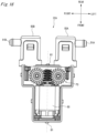
- the drive unit 80 is interposed between the cylinder 50A and the cylinder 50B.
- the drive unit 80 is arranged in front of the cylinder 50A and the cylinder 50B.
- the configuration where the cylinder 50A and the cylinder 50B are arranged at the bilaterally symmetrical positions about the drive shaft 81 of the drive unit 80 is the same as the generation main body part 22.
- the movement mechanism 70 includes the single worm 71 and the two worm wheels 72A, 72B.
- a movement mechanism 70a includes the single worm 71 and a single worm wheel 72.
- the worm wheel 72 is configured by a driven gear 73 and pinions 74A, 74B aligned in parallel and protruding toward one side (for example, the upper side shown in FIG. 17B ) of the driven gear 73.
- Gear teeth 75a, 75b of the pinions 74A, 74B are configured to mesh with the rack teeth 63A, 63B of the racks 62A, 62B.
- the two pinions 74A, 74B may be arranged to protrude laterally (for example, both sides in the upper and lower direction, in FIG. 17B ) from a central part of the driven gear 73 with the driven gear 73 being interposed therebetween.
- the two cylinders 50A, 50B are aligned in parallel with being adjacent to each other in the upper and lower direction, and the ejection ports 51A, 51B of the respective cylinders are provided to face toward the same direction (in this example, rightward).
- the single drive unit 80 is arranged at the left of the cylinders 50A, 50B.
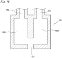
- the nozzle 3A (refer to FIGS. 10 to 12 ) of the above embodiment is formed with the cleaning liquid ejection port 31A configured to spray the cleaning liquid and the high-pressure air ejection port 32A configured to spray the high-pressure air, as independent separate ejection ports.
- a nozzle 130 of the modified embodiment is formed with one common ejection port 131, as the ejection port configured to spray the cleaning liquid and the ejection port configured to spray the high-pressure air.
- a passage 132A of the cleaning liquid and a passage 132B of the high-pressure air are separately formed in parallel, and the ejection port 131 is formed at a center of end portions of both the passages.
- the ejection port of the nozzle is configured by one ejection port, so that it is possible to miniaturize the nozzle 130. Also, since it is possible to simplify the structure of the nozzle 130, it is possible to easily manufacture the same.
- the present invention is not limited to the above embodiments, and can be appropriately modified and improved.
- the materials, shapes, sizes, numerical values, forms, numbers, arrangement places and the like of the constitutional elements of the above embodiments are arbitrary and are not particularly limited inasmuch as the present invention can be implemented.
Landscapes
- Engineering & Computer Science (AREA)
- Mechanical Engineering (AREA)
- Studio Devices (AREA)
- Nozzles (AREA)
- Lighting Device Outwards From Vehicle And Optical Signal (AREA)
- Superstructure Of Vehicle (AREA)
- Rear-View Mirror Devices That Are Mounted On The Exterior Of The Vehicle (AREA)
Description
- The present disclosure relates to a license plate lamp unit and a vehicle provided with a license plate lamp unit
- In recent years, vehicles having a vehicle-mounted camera configured to capture a situation around a vehicle have been increasing. A lens, which is an imaging surface, of the vehicle-mounted camera may be smudged due to rain, mud and the like. For this reason, in order to remove foreign matters such as water droplets attached on the lens, a device configured to remove the foreign matters by ejecting a cleaning liquid, a compressed air and the like to the lens of the vehicle-mounted camera has been known.
- For example,
PTL 1 discloses a configuration where a compressed air generation unit is provided in the vicinity of the vehicle-mounted camera, and a compressed air of the compressed air generation unit is sprayed from a nozzle to eject a high-pressure air to a front glass of the vehicle-mounted camera, thereby removing water droplets attached on the front glass (refer to PTL 1). - PTL 1:
JP-A-2001-171491 - In the configuration as disclosed in
PTL 1, when mounting a vehicle-mounted camera configured to capture a rear situation of the vehicle, a process of mounting the vehicle-mounted camera to a rear part of the vehicle and a process of mounting a nozzle to a position in which the foreign matters (particularly, mud and the like) attached on a front glass of the vehicle-mounted camera can be removed are performed. The mounting process of the respective components (vehicle-mounted camera, nozzle) is performed by adjusting the position between the components. Therefore, the mounting process is troublesome and the positional displacement among the components may occur. - Also, in the configuration as disclosed in
PTL 1, when mounting the vehicle-mounted camera configured to capture the rear situation of the vehicle, the vehicle-mounted camera is disposed in the vicinity of a license plate lamp configured to irradiate light to a license plate, for example. In this case, the light from the license plate lamp is incident on a lens of the vehicle-mounted camera, so that a part of an image captured by the camera becomes white, which lowers detection accuracy of the vehicle-mounted camera.US 2004/0124659 A1 describes a vehicle liftgate with component module applique. - The present disclosure is to provide a license plate lamp unit that, with a simple configuration, enables components to be easily mounted to a rear part of a vehicle and can prevent positional displacement among the components, and a vehicle equipped with the license plate lamp unit.
- Also, the present disclosure is to provide a license plate lamp unit that, with a simple configuration, can prevent light from a license plate lamp from being incident on a lens of a vehicle-mounted camera to thereby prevent lowering in detection accuracy of the vehicle-mounted camera, and a vehicle equipped with the license plate lamp unit.
- A license plate lamp unit of the present disclosure is defined in
claim 1. - According to the above configuration, the license plate lamp, the camera unit and the nozzle are mounted to the common base component and are thus modularized, so that the modularized license plate lamp unit can be easily mounted to an outer panel of a rear part of a vehicle, for example. Also, since each component is mounted to the common base component, it is possible to prevent positional displacement among the components.
- Deleted
- Also, the license plate lamp unit of the present invention may further include a door opening/closing part for opening and closing a rear door of a vehicle, and
the door opening/closing part may be supported to the base component. - According to the above configuration, the door opening/closing part can also be mounted to the common base component and modularized.
- Also, the license plate lamp unit of the present invention may further be defined in accordance with
claim 3. - Also, a vehicle of the present disclosure includes the license plate lamp unit having any one of the above-described configurations.
- According to the license plate lamp unit and the vehicle having the same in accordance with the present disclosure, it is possible to easily mount the license plate lamp unit to the rear part of the vehicle, and to prevent the positional displacement among the components.
- Also, according to the license plate lamp unit and the vehicle having the same in accordance with the present disclosure, it is possible to prevent the light from the license plate lamp from being incident on the vehicle-mounted camera with a simple configuration, thereby preventing lowering in detection accuracy of the vehicle-mounted camera.
-
-
FIG. 1 is a perspective view of a rear part of a vehicle having a vehicular cleaner system that configures a part of a license plate lamp unit in accordance with an embodiment. -
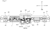
FIG. 2 is a front view depicting a high-pressure air generation unit, a nozzle and the like of the vehicular cleaner system. -
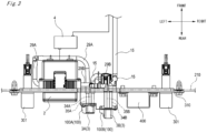
FIG. 3 is a plan view of the vehicular cleaner system shown inFIG. 2 . -
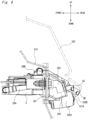
FIG. 4 is a left side view ofFIG. 2 . -
FIG. 5 is a sectional view taken along a line A-A ofFIG. 2 . -
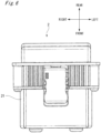
FIG. 6 is a plan view of the high-pressure air generation unit. -
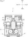
FIG. 7 is a sectional view depicting an inside of the high-pressure air generation unit shown inFIG. 6 . -
FIG. 8 is a plan view depicting a generation main body part of the high-pressure air generation unit. -
FIG. 9 is a sectional view of the generation main body part shown inFIG. 8 . -
FIG. 10 is an upper perspective view of the nozzle mounted to a vehicle-mounted camera. -
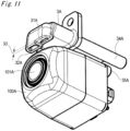
FIG. 11 is a lower perspective view of the nozzle mounted to the vehicle-mounted camera. -
FIG. 12 is a sectional view of the nozzle mounted to the vehicle-mounted camera. -
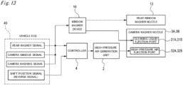
FIG. 13 is a block diagram for illustrating operations of the vehicular cleaner system. -
FIG. 14 is a timing chart for illustrating operations of the vehicular cleaner system. -
FIG. 15 is a timing chart for illustrating operations of the vehicular cleaner system. -
FIG. 16 is a plan view depicting a first modified embodiment of the generation main body part. -
FIG. 17A is a rear view depicting a second modified embodiment of the generation main body part. -
FIG. 17B is a plan view depicting the second modified embodiment of the generation main body part. -
FIG. 18 is a sectional view depicting a modified embodiment of the nozzle. - Hereinafter, an example of an embodiment will be described with reference to the drawings.
- A vehicular cleaner system, which configures a part of a license plate lamp unit of the present disclosure, is applied as a system configured to wash foreign matters such as water droplets, mud, grit and dust and the like attached to a vehicular lamp mounted to a vehicle, a vehicle-mounted sensor, a window of the vehicle or the like (examples of the to-be-cleaned object) by using a cleaning liquid and a high-pressure air (examples of a cleaning medium).
- As shown in
FIG. 1 , avehicular cleaner system 1 can be used to wash the foreign matters attached to a vehicle-mounted camera 100 (an example of the vehicle-mounted sensor and an example of the camera unit) mounted at a rear part of a vehicle V and arear window 200 of the vehicle V, for example. - The
vehicular cleaner system 1 includes awindow washer device 10 for spraying a cleaning liquid toward therear window 200 of the vehicle V. Thewindow washer device 10 includes atank 11 configured to accommodate therein the cleaning liquid, and a motor pump 12 (an example of the pump) configured to pressure-feed the cleaning liquid accommodated in thetank 11, and anozzle 13 configured to spray the cleaning liquid toward therear window 200. Thenozzle 13 is formed with an ejection port 14 (an example of the third ejection port) opening toward therear window 200. Thetank 11 and themotor pump 12 are arranged in a bonnet of the vehicle V, for example. Thenozzle 13 is coupled to themotor pump 12 through acoupling hose 15. In the meantime, thetank 11 and themotor pump 12 may be arranged at a rear side of the vehicle V. Thewindow washer device 10 can function as a device configured to clean a front window of the vehicle V, too. - The
window washer device 10 is controlled by a vehicle ECU (Electronic Controller) 40. For example, when a rear washer button (not shown) for cleaning therear window 200 is operated by a driver, thevehicle ECU 40 controls so that the cleaning liquid in thetank 11 is to be sprayed from theejection port 14 toward therear window 200. Also, after the cleaning liquid is sprayed, thevehicle ECU 40 controls arear wiper 201 so as to operate by a predetermined number of times. - Also, the
vehicular cleaner system 1 includes a high-pressureair generation unit 2 configured to generate a high-pressure air, anozzle 3 configured to spray the cleaning liquid and the high-pressure air toward the vehicle-mountedcamera 100, and a controller 4 configured to control the spraying of thenozzle 3. - The high-pressure
air generation unit 2 is mounted to a mounting member 310 (an example of a base component) to which alicense plate lamp 301 configured to irradiate light to alicense plate 300 is mounted, for example. Thenozzle 3 is formed integrally with a housing of the vehicle-mountedcamera 100, and is mounted to the mountingmember 310 together with the vehicle-mountedcamera 100. The mountingmember 310 is mounted to anouter panel 210 of the rear part of the vehicle, for example. In a state in which thelicense plate lamp 301, the vehicle-mountedcamera 100 and thenozzle 3 are mounted to the mountingmember 310, the mountingmember 310 is mounted to theouter panel 210 from an outside. The mountingmember 310 mounted to theouter panel 210 is covered from an upper side by agarnish 320. The controller 4 is arranged in theouter panel 210, for example, and is connected to thevehicle ECU 40 configured to control thewindow washer device 10. Also, the controller 4 is connected to the high-pressureair generation unit 2. In the meantime, a configuration where the processing of the controller 4 is executed by thevehicle ECU 40 and the controller is thus integrated is also possible. A door opener 400 (an example of a door opening/closing part) for opening and closing a rear door of the vehicle is also mounted to the mountingmember 310. Thelicense plate lamp 301 has alight emission unit 302 configured to irradiate light to the license plate. - As shown in
FIGS. 2 ,3 ,4 and5 , the vehicle-mountedcamera 100 mounted to the mountingmember 310 includes, for example, aninner mirror camera 100A and arearview camera 100B. Theinner mirror camera 100A and therearview camera 100B havelenses inner mirror camera 100A is a camera for capturing a rear situation (image) that can be checked by an inner mirror (rearview mirror), and is configured to operate while at least an engine of the vehicle V is on. Therearview camera 100B is a camera for capturing an image in the vicinity of the rear of the vehicle V, and operates when a gear of the vehicle V is switched to a reverse state, for example. The images captured by theinner mirror camera 100A and therearview camera 100B are displayed on a monitor (not shown) provided in a vehicle interior, for example. - A
nozzle 3A mounted to theinner mirror camera 100A is coupled to themotor pump 12 of thewindow washer device 10 through thecoupling hose 15 and is coupled to the high-pressureair generation unit 2 through acoupling hose 29A. Anozzle 3B mounted to therearview camera 100B is coupled to themotor pump 12 of thewindow washer device 10 through thecoupling hose 15 and is coupled to the high-pressureair generation unit 2 through acoupling hose 29B. Thetank 11 and themotor pump 12 for thewindow washer device 10 are used as a tank and a motor pump for spraying the cleaning liquid for cleaning theinner mirror camera 100A and therearview camera 100B, too. - As shown in
FIG. 4 , theinner mirror camera 100A is mounted to face toward the substantial right rear of the vehicle V Also, as shown inFIG. 5 , therearview camera 100B is mounted to the rear of the vehicle V in an obliquely downward direction. Thelens 100A of theinner mirror camera 100A is located below a lower end of thelight emission unit 302 of thelicense plate lamp 301, and is also located at the rear of a rear end of thelight emission unit 302. More specifically, thelens 100A of theinner mirror camera 100A is located below a lower end of alight emission surface 303 of thelight emission unit 302 of thelicense plate lamp 301 and is also located at the rear of a rear end of thelight emission unit 303. Also, thelens 100B of therearview camera 100B is located below the lower end of thelight emission unit 302 of thelicense plate lamp 301 and is also located at the rear of the rear end of thelight emission unit 302. More specifically, thelens 100B of therearview camera 100B is located below the lower end of thelight emission surface 303 of thelight emission unit 302 of thelicense plate lamp 301 and is also located at the rear of the rear end of thelight emission unit 303. - In the embodiment, the
lens 101A and thelens 100B are located below the lower end of thelight emission unit 302 of thelicense plate lamp 301 and at the rear end of the light emission unit. However, the present disclosure is not limited thereto. For example, thelens 101A and thelens 100B may be located below the lower end of thelight emission unit 302 of thelicense plate lamp 301 or at the rear of the rear end of thelight emission unit 302. - As shown in
FIGS. 6 and7 , the high-pressureair generation unit 2 includes ahousing 21, a generationmain body part 22 accommodated in thehousing 21, and a control unit (control substrate) 23 configured to control operations of the generationmain body part 22. The generationmain body part 22 is mounted to thehousing 21 via adamper 24. - As shown in
FIGS. 8 and9 , the generationmain body part 22 includes a plurality of (two, in the example)cylinders pistons main body part 22 includes amovement mechanism 70 configured to apply a moving force to thepistons single drive unit 80 configured to drive themovement mechanism 70. - The
cylinder 50A and thecylinder 50B are arranged at bilaterally symmetrical positions about adrive shaft 81 of thedrive unit 80. Also, in the example, thedrive unit 80 is interposed between thecylinder 50A and thecylinder 50B. - The
cylinder 50A has anejection port 51A for delivering the high-pressure air toward thenozzle 3A for theinner mirror camera 100A. Thecylinder 50B has anejection port 51B for delivering the high-pressure air toward thenozzle 3B for therearview camera 100B. Theejection port 51A of thecylinder 50A is formed to face toward an opposite direction to theejection port 51B of thecylinder 50B (in the example, theejection port 51A faces leftward and theejection port 51B faces rightward). Theejection port 51A is coupled with thecoupling hose 29A communicating with thenozzle 3A. Theejection port 51B is coupled with thecoupling hose 29B communicating with thenozzle 3B. - The
cylinders main body part 22 are detachably configured. Thehousing 90 of the generationmain body part 22 is formed with concave parts 91 (an example of the first engaging part). Outer surfaces of thecylinders convex parts convex parts cylinders concave parts 91 of thehousing 90, so that thecylinders housing 90. - The
pistons cylinders pistons cylinders pistons pistons cylinders ejection ports pistons cylinders - Front end portions of the
pistons racks racks cylinders pistons racks rack teeth rack tooth 63A of therack 62A protrudes toward therack 62B (toward the rightward direction), and therack tooth 63B of therack 62B protrudes toward therack 62A (toward the leftward direction). - The
movement mechanism 70 includes asingle worm 71 configured to rotate by thedrive unit 80 and a plurality of (in the example, two)worm wheels worm 71 and to rotate in association with rotation of theworm 71. - The
worm 71 is fixed to thedrive shaft 81 extending forward from thedrive unit 80 and is configured to rotate in association with rotation of thedrive shaft 81. - The
worm wheels shaft parts housing 90 via bearings. Theworm wheel 72A and theworm wheel 72B are arranged at bilaterally symmetrical positions about theworm 71. - The
respective worm wheels pinions worm 71, and are configured to rotate in association with rotation of theworm 71. Thepinions gear 73A and thepinion 74A are configured to rotate in a clockwise direction and the drivengear 73B and thepinion 74B are configured to rotate in a counterclockwise direction, inFIGS. 8 and9 . - Outer peripheral parts of the
pinions gear teeth gear teeth 75A of thepinion 74A can mesh with therack tooth 63A of therack 62A, and thegear teeth 75B of thepinion 74B can mesh with therack tooth 63B of therack 62B. In the meantime, positions at which thegear teeth 75A of thepinion 74A are formed in an outer periphery direction of thepinion 74A and positions at which thegear teeth 75B of thepinion 74B are formed in an outer periphery direction of thepinion 74B may be bilaterally symmetrical or may be asymmetrical about theworm 71. For example, in the asymmetrical case, a phase of thepiston 60A and a phase of thepiston 60B configured to reciprocally move in the front and rear direction are different. - In the generation
main body part 22 configured as described above, when thedrive unit 80 is driven under predetermined conditions, theworm 71 is rotated, so that the driven gears 73A, 73B of theworm wheels worm 71 are respectively rotated in opposite circumferences. When the driven gears 73A, 73B are rotated, thepinions gear teeth pinions rack teeth racks pinions racks gear teeth pistons racks cylinders pinions rack teeth gear teeth pistons pistons cylinders respective ejection ports nozzle - As shown in
FIGS. 10 to 12 , thenozzle 3A mounted to theinner mirror camera 100A has a cleaningliquid ejection port 31A (an example of the first ejection port) configured to spray the cleaning liquid toward alens 101A (an example of the cleaning surface) of theinner mirror camera 100A and a high-pressureair ejection port 32A (an example of the second ejection port) configured to spray the high-pressure air toward thelens 101A. In the meantime, since thenozzle 3B mounted to therearview camera 100B has the same configuration as thenozzle 3A, the respective corresponding parts are denoted with the reference numerals "B" replaced with "A", and thenozzle 3B is described focusing on differences from thenozzle 3A. - The cleaning
liquid ejection port 31A and the high-pressureair ejection port 32A are formed in thesingle nozzle 3A, as independent separate ejection ports. The cleaningliquid ejection port 31A and the high-pressureair ejection port 32A are aligned in parallel in the right and left direction on the same side surface (in the example, the upper surface) of theinner mirror camera 100A. The high-pressureair ejection port 32A is arranged at a position facing a central part of thelens 101A. The cleaningliquid ejection port 31A is arranged at a position (in the example, a position deviating rightward) deviating from the central part of thelens 101A. That is, the cleaningliquid ejection port 31A is formed at a position more distant from thelens 101A than the high-pressureair ejection port 32A. Also, astep 33 stepped in the upper and lower direction is formed between the cleaningliquid ejection port 31A and the high-pressureair ejection port 32A. - The cleaning
liquid ejection port 31A is configured to communicate with atube path 34A through which the cleaning liquid is to pass. Also, the high-pressureair ejection port 32A is configured to communicate with atube path 35A through which the high-pressure air is to pass. Thetube paths inner mirror camera 100A. - The
tube paths rear end port 36A of thetube path 34A is formed smaller than a diameter of arear end port 37A of thetube path 35A (refer toFIG. 12 ). Therear end port 36A and the cleaningliquid ejection port 31A are formed to communicate with each other by theejection path 38A, and therear end port 37A and the high-pressureair ejection port 32A are formed to communicate with each other by theejection path 39A. Theejection path 38A and theejection path 39A are formed so that they are wider toward theejection ports ejection path 38A is formed greater than an ejection angle θ2 of theejection path 39A. Theejection path 38A is obliquely formed in a right and lower direction toward a central point of thelens 101A. Theejection path 39A is formed downward toward the central point of thelens 101A. - A front end portion of the
tube path 34A is coupled with thecoupling hose 15 communicating with themotor pump 12 of thewindow washer device 10. A front end portion of thetube path 35A is coupled with thecoupling hose 29A communicating with thecylinder 50A. In the meantime, a front end portion of atube path 34B of thenozzle 3B of therearview camera 100B is coupled with thecoupling hose 15 communicating with themotor pump 12 of thewindow washer device 10, and a front end portion of atube path 35B is coupled with thecoupling hose 29B communicating with thecylinder 50B. - In the example, the cleaning
liquid ejection port 31A and the high-pressureair ejection port 32A are aligned in parallel in the right and left direction on the upper surface of theinner mirror camera 100A. However, the present invention is not limited thereto. For example, the cleaningliquid ejection port 31A and the high-pressureair ejection port 32A may be respectively arranged on different side surfaces of theinner mirror camera 100A. In this case, preferably, the high-pressureair ejection port 32A is arranged at a position at which the high-pressure air is to be sprayed toward thelens 101A from one direction in the upper and lower direction, and the cleaningliquid ejection port 31A is arranged at a position at which the cleaning liquid is to be sprayed toward thelens 101A from one direction in the right and left direction. In the meantime, for example, when the vehicle-mounted camera is mounted to the front part of the vehicle, the high-pressure air ejection port is preferably arranged below the lens, considering a wind pressure from the front. - The controller 4 and the
vehicle ECU 40 can switchably execute an actuation mode in which the cleaning liquid and the high-pressure air are to be sprayed toward the cleaning surface for cleaning and an actuation mode in which only the high-pressure air is to be sprayed toward the cleaning surface for cleaning, for example. In this case, the controller 4 and thevehicle ECU 40 can switchably execute the two actuation modes, depending on a type of the to-be-cleaned object, for example. Also, in the case of the actuation mode in which the cleaning liquid and the high-pressure air are to be sprayed toward the cleaning surface for cleaning, the controller 4 and thevehicle ECU 40 can initiate the spraying of the high-pressure air from the high-pressureair ejection port 32A of thenozzle 3A after the spraying of the cleaning liquid from the cleaningliquid ejection port 31A of thenozzle 3A has been initiated, for example, - Also, the controller 4 and the
vehicle ECU 40 can switchably execute an actuation mode in which the cleaning liquid is to be sprayed from both the cleaningliquid ejection port 31A of thenozzle 3A and theejection port 14 of thenozzle 13 and an actuation mode in which the cleaning liquid is to be sprayed from only one of the cleaningliquid ejection port 31A of thenozzle 3A and theejection port 14 of thenozzle 13. - Subsequently, operations of the
vehicular cleaner system 1 are described with reference toFIGS. 13 to 15 . - As shown in
FIGS. 13 and14 , for example, when the rear washer button for cleaning therear window 200 of the vehicle V is pushed, a rear washer signal is transmitted from thevehicle ECU 40 to themotor pump 12 of thewindow washer device 10 and the controller 4. - The
motor pump 12 having received the rear washer signal pressure-feeds the cleaning liquid in thetank 11 to thenozzle 13 of thewindow washer device 10, thenozzle 3A of theinner mirror camera 100A and thenozzle 3B of therearview camera 100B through thecoupling hose 15. The cleaning liquid pressure-fed to thenozzle 13 is sent from thecoupling hose 15 to theejection port 14 of thenozzle 13 and is sprayed toward therear window 200. The cleaning liquid pressure-fed to thenozzle 3A passes through thetube path 34A from thecoupling hose 15, is sent to the cleaningliquid ejection port 31A, and is then sprayed toward thelens 101A of theinner mirror camera 100A. The cleaning liquid pressure-fed to thenozzle 3B passes through thetube path 34B from thecoupling hose 15, is sent to the cleaningliquid ejection port 31B and is then sprayed toward thelens 100B of therearview camera 100B. - Time T1 for which the
rear window 200 is to be washed on the basis of one rear washer signal can be arbitrarily set. Also, the washing of theinner mirror camera 100A and therearview camera 100B based on one rear washer signal is implemented in synchronization with a cleaning operation of cleaning therear window 200. Therefore, the time for which theinner mirror camera 100A and therearview camera 100B are to be washed becomes the same length as time T1 for which therear window 200 is to be washed (or control may be performed so that the time is to be different from time T1). - The controller 4 having received the rear washer signal transmits a high-pressure air generation signal for operating the high-pressure
air generation unit 2 toward thecontrol unit 23 after predetermined time T2 has elapsed from completion of the cleaning of therear window 200, based on time T1 for which therear window 200 is washed. Thecontrol unit 23 operates the generationmain body part 22 of the high-pressureair generation unit 2 to generate the high-pressure air, and delivers the generated high-pressure air toward thenozzle 3A of theinner mirror camera 100A and thenozzle 3B of therearview camera 100B. - The high-pressure air delivered to the
nozzle 3A passes through thecoupling hose 29A and thetube path 35A from theejection port 51A of thecylinder 50A, is sent to the high-pressureair ejection port 32A, and is then sprayed toward thelens 101A of theinner mirror camera 100A. The high-pressure air delivered to thenozzle 3B passes through thecoupling hose 29B and thetube path 35B from theejection port 51B of thecylinder 50B, is sent to the high-pressureair ejection port 32B and is then sprayed toward thelens 100B of therearview camera 100B. The spraying of the high-pressure air is implemented with delay time T2 from completion of the cleaning of therear window 200 by the cleaning liquid. Time T3 for which the cleaning is to be performed by the high-pressure air can be arbitrarily set. - Also, as shown in
FIGS. 13 and14 , when the gear of the vehicle V is shifted to the reverse position, for example, a reverse signal is transmitted from thevehicle ECU 40 to the controller 4. - The controller 4 having received the reverse signal transmits a high-pressure air generation signal for operating the high-pressure
air generation unit 2 toward thecontrol unit 23, after predetermined time T4 has elapsed from the shift of the gear. Thecontrol unit 23 operates the generationmain body part 22 of the high-pressureair generation unit 2 to generate a high-pressure air, and delivers the generated high-pressure air to thenozzle 3A of theinner mirror camera 100A and thenozzle 3B of therearview camera 100B. - The high-pressure air delivered to the
nozzle 3A and thenozzle 3B is sprayed from the high-pressureair ejection port 32A and the high-pressureair ejection port 32B toward the respective camera lenses, like the case where the rear washer button is pushed. Time T5 for which the cleaning is to be performed by the high-pressure air can be arbitrarily set. Like this, the spraying of the cleaning liquid may be sprayed toward theinner mirror camera 100A and therearview camera 100B, depending on the change in shift position of the gear, without synchronizing with the spraying toward therear window 200. In the meantime, when the gear is shifted to the reverse position, the controller 4 may spray the high-pressure air only from thenozzle 3B of therearview camera 100B without spraying the high-pressure air from thenozzle 3A of theinner mirror camera 100A. - Also, as shown in
FIGS. 13 and15 , for example, when it is recognized that thelens 100A of theinner mirror camera 100A or thelens 100B of therearview camera 100B is smudged, a camera smudge signal is transmitted from thevehicle ECU 40 to themotor pump 12 of thewindow washer device 10 and the controller 4. Whether the lens is smudged is recognized on the basis of the image data captured by each camera, for example. - The
motor pump 12 having received the camera smudge signal pressure-feeds the cleaning liquid in thetank 11 to thenozzle 3A of theinner mirror camera 100A and thenozzle 3B of therearview camera 100B through thecoupling hose 15. The pressure-fed cleaning liquid is sprayed from the cleaningliquid ejection port 31A of thenozzle 3A toward thelens 100A of theinner mirror camera 100A and from the cleaningliquid ejection port 31B of thenozzle 3B toward thelens 101B of therearview camera 100B. In the meantime, when the camera smudge signal is transmitted, the cleaning of therear window 200 is not implemented. In this case, for example, a flow path switching unit for switching a flow path of the cleaning liquid is provided on the way of thecoupling hose 15, and when the camera smudge signal is transmitted, the flow path switching unit is controlled to enable the cleaning liquid to flow toward only thenozzles lenses cameras lenses - The controller 4 having received the camera smudge signal transmit a high-pressure air generation signal for operating the high-pressure
air generation unit 2 toward thecontrol unit 23, after predetermined time T2 has elapsed from completion of the cleaning of thelenses lenses air ejection port 32A and the high-pressureair ejection port 32B toward thelens 100A of theinner mirror camera 100A and thelens 100B of therearview camera 100B. The spraying of the high-pressure air is implemented with delay time T2 from completion of the spraying of thelenses - Also, as shown in
FIGS. 13 and15 , for example, a camera washing button (an actuation switch) for cleaning the vehicle-mounted camera may be provided in the vehicle interior, thevehicle ECU 40 may determine whether the camera washing button is pushed, and the spraying of the cleaning liquid toward theinner mirror camera 100A and therearview camera 100B may be controlled. Specifically, when the camera washing button is pushed, a camera washing signal is transmitted from thevehicle ECU 40 to themotor pump 12 of thewindow washer device 10 and the controller 4. - The operations of the
motor pump 12 and the controller 4 having received the camera washing signal are the same as the operations of themotor pump 12 and the controller 4, which are performed when the lens of the camera is recognized as being smudged and the camera smudge signal is received. - In the meantime, in the respective operations, when cleaning the
inner mirror camera 100A and therearview camera 100B, the two-type cleaning by the spraying of the cleaning liquid and the spraying of the high-pressure air is performed for both the cameras. However, the present invention is not limited thereto. For example, the two-type cleaning by the spraying of the cleaning liquid and the spraying of the high-pressure air may be performed for theinner mirror camera 100A, and the cleaning only by the spraying of the high-pressure air may be performed for therearview camera 100B, and vice versa. - Also, in the embodiment, the
vehicular cleaner system 1 includes the high-pressure generation unit 2 configured to generate and deliver the high-pressure air, and thenozzle 3 configured to spray the high-pressure air toward the vehicle-mountedcamera 100. However, the present disclosure is not limited thereto. For example, the vehicular cleaner system may include a blowing unit configured to deliver air without compressing the air, and a nozzle configured to deliver the air delivered from the blowing unit toward the vehicle-mounted camera. - The
vehicular cleaner system 1 configured as described above has the actuation mode in which the cleaning liquid and the high-pressure air are to be sprayed toward the vehicle-mountedcamera 100 and the actuation mode in which only the high-pressure air is to be sprayed toward the vehicle-mountedcamera 100, and can switch the modes by the controller. Therefore, it is possible to effectively remove the foreign matters attached to the vehicle-mountedcamera 100 with the simple configuration. - Also, the
vehicular cleaner system 1 can switch the actuation mode in which the cleaning liquid and the high-pressure air are to be sprayed and the actuation mode in which only the high-pressure air is to be sprayed, depending on the type of the to-be-cleaned object. Therefore, it is possible to clean a variety of the to-be-cleaned objects by the appropriate method. In this case, for example, the cleaning liquid and the high-pressure air can be sprayed toward theinner mirror camera 100A, which is to be operated while at least the engine is on, and the high-pressure air can be sprayed toward therearview camera 100B, which is to be operated when the gear is switched to the reverse position. Therefore, while securing the high cleaning ability for theinner mirror camera 100A that is to be frequently used, it is possible to suppress the consumption of themotor pump 12 and the cleaning liquid. - Also, for example, when cleaning the
inner mirror camera 100A, thevehicular cleaner system 1 can control so that the spraying of the high-pressure air from the high-pressureair ejection port 32A can be initiated after the spraying of the cleaning liquid from the cleaningliquid ejection port 31A of thenozzle 3A has been initiated. Therefore, it is possible to effectively remove the foreign matters attached to theinner mirror camera 100A with the simple configuration. - Also, the
vehicular cleaner system 1 has the actuation mode in which the cleaning liquid is to be sprayed from both the cleaningliquid ejection port 31A of thenozzle 3A and theejection port 14 of thenozzle 13 and the actuation mode in which the cleaning liquid is to be sprayed from only one of the cleaningliquid ejection port 31A and theejection port 14, and can switch the modes by the controller. Therefore, the modes are switched depending on the situations, so that it is possible to suppress lowering in lifetime of themotor pump 12 and consumption of the cleaning liquid. - Also, for example, the
vehicular cleaner system 1 may be provided with an actuation switch (camera washing button), which can be set by a driver, in the vehicle interior, and when the actuation switch is on, thevehicular cleaner system 1 can control so that the cleaning liquid is to be sprayed toward the vehicle-mountedcamera 100. Therefore, it is possible to execute the spraying of the cleaning liquid and the high-pressure air toward the vehicle-mountedcamera 100, depending on whether the driver turns on or off the actuation switch. - Also, for example, the spraying of the high-pressure air from the high-pressure
air ejection port 32A is initiated after time T2 has elapsed from completion of the spraying of the cleaning liquid from the cleaningliquid ejection port 31A of thenozzle 3A for theinner mirror camera 100A. For this reason, it is possible to prevent the cleaning liquid, which is to be sprayed from the cleaningliquid ejection port 31A, from being introduced to the high-pressureair ejection port 32A for the high-pressure air. - Also, the tank and the motor pump, which are used so as to spray the cleaning liquid toward the vehicle-mounted
camera 100, are used as thetank 11 and themotor pump 12 of thewindow washer device 10 for spraying the cleaning liquid toward the window of the vehicle, too. Therefore, the cleaning liquid that is to be used for thewindow washer device 10 can be used as the cleaning liquid for cleaning the vehicle-mounted sensor100 and the like, too, so that it is possible to remove the foreign matters with the convenience configuration. - Also, for example, the
nozzle 3A mounted to theinner mirror camera 100A has the cleaningliquid ejection port 31A configured to spray the cleaning liquid and the high-pressureair ejection port 32A configured to spray the high-pressure air, which are independently provided. For this reason, the high-pressure air and the cleaning liquid are independently sprayed to the same to-be-cleaned object (theinner mirror camera 100A), so that it is possible to effectively remove the foreign matters attached to the to-be-cleaned object. - Also, the cleaning
liquid ejection port 31A of thenozzle 3A is formed at the position more distant from thelens 100A than the high-pressureair ejection port 32A. For this reason, when cleaning thelens 100A by using the cleaning liquid and the high-pressure air, it is possible to prevent the cleaning liquid of the cleaningliquid ejection port 31A from being introduced upon the spraying of the high-pressure air from the high-pressureair ejection port 32A. Also, the ejection angle θ1 of theejection path 38A in the cleaningliquid ejection port 31A is formed greater than the ejection angle θ2 of theejection path 39A in the high-pressureair ejection port 32A. For this reason, it is possible to widen a spraying area of the cleaning liquid from the cleaningliquid ejection port 31A arranged more distant from thelens 100A than the high-pressureair ejection port 32A. - Also, the cleaning
liquid ejection port 31A and the high-pressureair ejection port 32A of thenozzle 3A are aligned in parallel on the upper surface of theinner mirror camera 100A, for example. For this reason, it is possible to downsize thenozzle 3A. Also, the high-pressureair ejection port 32A is arranged at the position facing the central part of thelens 101A on the upper surface of theinner mirror camera 100A. For this reason, the high-pressure air, which is more susceptible to surrounding environments (for example, weather conditions such as wind) than the cleaning liquid, can be appropriately sprayed toward thelens 101A. Also, thestep 33 stepped in the upper and lower direction is formed between the cleaningliquid ejection port 31A and the high-pressureair ejection port 32A. For this reason, it is possible to prevent the cleaning liquid, which is to be sprayed from the cleaningliquid ejection port 31A, from being introduced into the high-pressureair ejection port 32A for the high-pressure air. - Also, the cleaning
liquid ejection port 31A can be arranged so as to spray the cleaning liquid from a direction different from the spraying direction of the high-pressure air from the high-pressureair ejection port 32A. In this case, it is possible to prevent the spraying of the high-pressure air and the spraying of the cleaning liquid from interfering with each other. For example, the high-pressureair ejection port 32A may be arranged at a position at which the high-pressure air is to be sprayed toward thelens 101A from one direction in the upper and lower direction, and the cleaningliquid ejection port 31A may be arranged at a position at which the cleaning liquid is to be sprayed toward thelens 101A from one direction in the right and left direction. In this case, the high-pressure air, which is more susceptible to the exterior air environment than the cleaning liquid, can be appropriately sprayed toward the cleaning surface. - Also, the high-pressure
air generation unit 2 for generating the high-pressure air is provided with the twopistons movement mechanism 70 and thecylinders single drive unit 80. For this reason, it is possible to effectively remove the foreign matters attached to the plurality of vehicle-mountedcameras 100 with the simple configuration. - Also, the
movement mechanism 70 includes thesingle worm 71 configured to rotate by thesingle drive unit 80 and the twoworm wheels worm 71. For this reason, it is possible to form the high-pressureair generation unit 2 having a plurality of cylinders with the simple configuration. - Also, the
cylinder 50A and thecylinder 50B are arranged at symmetrical positions about thedrive shaft 81 of thedrive unit 80. For this reason, it is possible to thin the high-pressureair generation unit 2 and to cancel vibrations to be generated from therespective cylinders drive unit 80 is interposed between thecylinder 50A and thecylinder 50B, it is possible to further miniaturize the high-pressureair generation unit 2. Also, since theejection port 51A of thecylinder 50A is formed to face toward the opposite direction to theejection port 51B of the cylinder, it is possible to further cancel the vibrations upon the spraying of the high-pressure air. - Also, the phase of the
piston 60A of thecylinder 50A and the phase of thepiston 60B of thecylinder 50B may be configured to be different from each other. In this case, it is possible to spray the high-pressure air toward the plurality of vehicle-mountedcameras 100 at different timings. - Also, the
cylinders housing 90 of the generationmain body part 22 have engaging parts to be engaged with each other. For this reason, thecylinders housing 90 of the generationmain body part 22. - Also, the
license plate lamp 301, the vehicle-mountedcamera 100 and thenozzle 3 are supported to the common mountingmember 310. Also, the high-pressure air 2 and thedoor opener 400 are also supported to the mountingmember 310. For this reason, it is possible to easily mount the license plate lamp unit, in which the corresponding components are modularized, to theouter panel 210 of the rear part of the vehicle, for example. Also, since the respective components are mounted to the common mountingmember 310, it is possible to prevent positional displacement among the components. - Also, the
camera lenses light emission unit 302 of thelicense plate lamp 301, and/or are located at the rear of the rear end of thelight emission unit 302. In this way, it is possible to prevent the light from the license plate lamp from being incident on the camera lenses by adjusting the positions of thecamera lenses light emission unit 302 of thelicense plate lamp 301. - In the below, a first modified embodiment of the generation
main body part 22 of the high-pressureair generation unit 2 is described with reference toFIG. 16 . In the meantime, since the parts denoted with the same reference numerals as the above embodiment have the same functions, the overlapping descriptions thereof are omitted. - In the generation main body part 22 (refer to
FIG. 8 ) of the above embodiment, thedrive unit 80 is interposed between thecylinder 50A and thecylinder 50B. In contrast, as shown inFIG. 16 , in a generationmain body part 22A of the first modified embodiment, thedrive unit 80 is arranged in front of thecylinder 50A and thecylinder 50B. In the meantime, the configuration where thecylinder 50A and thecylinder 50B are arranged at the bilaterally symmetrical positions about thedrive shaft 81 of thedrive unit 80 is the same as the generationmain body part 22. - According to the above configuration, since the
cylinder 50A and thecylinder 50B are arranged at the symmetrical positions, it is possible to cancel the vibrations that are to be generated upon the operations of the cylinders. - In the below, a second modified embodiment of the generation
main body part 22 of the high-pressureair generation unit 2 is described with reference toFIGS. 17A and 17B . In the meantime, the overlapping descriptions of the parts denoted with the same reference numerals as the above embodiment are omitted, like the first modified embodiment. - In the generation main body part 22 (refer to
FIG. 8 ) of the above embodiment, themovement mechanism 70 includes thesingle worm 71 and the twoworm wheels main body part 22B of the second modified embodiment, amovement mechanism 70a includes thesingle worm 71 and asingle worm wheel 72. Theworm wheel 72 is configured by a drivengear 73 andpinions FIG. 17B ) of the drivengear 73.Gear teeth pinions rack teeth racks pinions FIG. 17B ) from a central part of the drivengear 73 with the drivengear 73 being interposed therebetween. - As shown in
FIG. 17A , the twocylinders ejection ports single drive unit 80 is arranged at the left of thecylinders - According to the above configuration, since it is possible to reduce a width of the generation
main body part 22B in the right and left direction, it is possible to miniaturize the high-pressureair generation unit 2. - In the below, a modified embodiment of the
nozzle camera 100 is described with reference toFIG. 18 . In the meantime, since the parts denoted with the same reference numerals as the above embodiment have the same functions, the overlapping descriptions thereof are omitted. - The
nozzle 3A (refer toFIGS. 10 to 12 ) of the above embodiment is formed with the cleaningliquid ejection port 31A configured to spray the cleaning liquid and the high-pressureair ejection port 32A configured to spray the high-pressure air, as independent separate ejection ports. In contrast, as shown inFIG. 18 , anozzle 130 of the modified embodiment is formed with onecommon ejection port 131, as the ejection port configured to spray the cleaning liquid and the ejection port configured to spray the high-pressure air. In thenozzle 130, apassage 132A of the cleaning liquid and apassage 132B of the high-pressure air are separately formed in parallel, and theejection port 131 is formed at a center of end portions of both the passages. - According to the above configuration, the ejection port of the nozzle is configured by one ejection port, so that it is possible to miniaturize the
nozzle 130. Also, since it is possible to simplify the structure of thenozzle 130, it is possible to easily manufacture the same. - In the meantime, the present invention is not limited to the above embodiments, and can be appropriately modified and improved. In addition, the materials, shapes, sizes, numerical values, forms, numbers, arrangement places and the like of the constitutional elements of the above embodiments are arbitrary and are not particularly limited inasmuch as the present invention can be implemented.
- The subject application is based on
Japanese Patent Application Nos. 2017-165452 filed on August 30, 2017 2017-185038
Claims (4)
- A license plate lamp unit comprising:a license plate lamp (301) configured to irradiate light to a license plate (300);a camera unit having a camera lens (101A,101B); characterized bya nozzle (3, 3A, 3B) configured to discharge a cleaning liquid and high-pressure air toward the camera lens (101A,101B);a delivery unit configured to deliver high-pressure air toward the nozzle (3, 13); anda base component (310) configured to support the license plate lamp (301), the camera unit, the delivery unit and the nozzle (3, 3A, 3B);
- The license plate lamp unit according to Claim 1, further comprising:a door opening/closing part (400) for opening and closing a rear door of a vehicle,wherein the door opening/closing part is supported to the base component (310).
- The license plate lamp unit according to Claim 1, wherein the nozzle is formed with a cleaning liquid ejection port (31A, 31B) configured to spray the cleaning liquid and a high-pressure air ejection port (32A, 32B) configured to spray the high-pressure air, as independent separate ejection ports.
- A vehicle comprising the license plate lamp unit according to any one of Claims 1 to 3.
Applications Claiming Priority (3)
| Application Number | Priority Date | Filing Date | Title |
|---|---|---|---|
| JP2017165452 | 2017-08-30 | ||
| JP2017185038 | 2017-09-26 | ||
| PCT/JP2018/029442 WO2019044402A1 (en) | 2017-08-30 | 2018-08-06 | License plate lamp unit and vehicle provided with license plate lamp unit |
Publications (3)
| Publication Number | Publication Date |
|---|---|
| EP3677478A1 EP3677478A1 (en) | 2020-07-08 |
| EP3677478A4 EP3677478A4 (en) | 2021-05-19 |
| EP3677478B1 true EP3677478B1 (en) | 2024-11-06 |
Family
ID=65527473
Family Applications (1)
| Application Number | Title | Priority Date | Filing Date |
|---|---|---|---|
| EP18851025.9A Active EP3677478B1 (en) | 2017-08-30 | 2018-08-06 | License plate lamp unit and vehicle provided with license plate lamp unit |
Country Status (5)
| Country | Link |
|---|---|
| US (1) | US11535201B2 (en) |
| EP (1) | EP3677478B1 (en) |
| JP (1) | JP7555707B2 (en) |
| CN (1) | CN111032451B (en) |
| WO (1) | WO2019044402A1 (en) |
Families Citing this family (9)
| Publication number | Priority date | Publication date | Assignee | Title |
|---|---|---|---|---|
| JP6841159B2 (en) | 2017-05-24 | 2021-03-10 | トヨタ自動車株式会社 | Driving support device |
| FR3096001B1 (en) * | 2019-05-17 | 2022-04-15 | A Raymond Et Cie | Arrangement for mounting an optical system on a bodywork element of a vehicle |
| CN112158147A (en) * | 2020-10-27 | 2021-01-01 | 中拜出行科技股份有限公司 | Net appointment car license plate display device |
| FR3121104A1 (en) * | 2021-03-23 | 2022-09-30 | Valeo Systemes D'essuyage | Device for cleaning a sensing surface of a sensing device. |
| DE102021115367B4 (en) | 2021-06-14 | 2024-05-29 | Webasto SE | Roof module for forming a vehicle roof with a cleaning device |
| CN114604186B (en) * | 2022-03-23 | 2023-04-25 | 山东交通学院 | Vehicle danger accident warning robot capable of achieving instant investigation |
| CN115853381B (en) * | 2022-12-02 | 2023-08-08 | 浙江铁印汽车部件有限公司 | Electric stay bar, vehicle-mounted lubricating system and use method of system |
| WO2024218152A1 (en) * | 2023-04-17 | 2024-10-24 | Valeo Systèmes d'Essuyage | Device for cleaning a detection surface of a detection device |
| TWI852546B (en) * | 2023-05-10 | 2024-08-11 | 曹育民 | Car wiper tank |
Citations (2)
| Publication number | Priority date | Publication date | Assignee | Title |
|---|---|---|---|---|
| US20110073142A1 (en) * | 2009-09-29 | 2011-03-31 | Denso Corporation | On-board optical sensor cover and on-board optical apparatus |
| EP2631734A1 (en) * | 2012-02-23 | 2013-08-28 | The Raymond Corporation | Method and apparatus for removing and preventing lens surface fogging on a vehicle lens |
Family Cites Families (19)
| Publication number | Priority date | Publication date | Assignee | Title |
|---|---|---|---|---|
| JPS62177572U (en) * | 1986-04-30 | 1987-11-11 | ||
| JP2001171491A (en) | 1999-12-16 | 2001-06-26 | Matsushita Electric Ind Co Ltd | Vehicle-mounted camera device and method of cleaning vehicle-mounted camera |
| US6834906B2 (en) * | 2002-12-30 | 2004-12-28 | Valeo Electrical Systems, Inc. | Vehicle liftgate with component module applique |
| FR2859426B1 (en) * | 2003-09-10 | 2006-12-08 | Valeo Systemes Dessuyage | EQUIPMENT MODULE TRIM WITH A WALL HAVING A REAR VISION CAMERA |
| FR2875473A1 (en) * | 2004-09-23 | 2006-03-24 | Valeo Systemes Dessuyage | Accessory e.g. rear license plate lighting unit, support module for rear frame of vehicle, has fixation units to fix lights of license plate, rear frame opening actuating device, antenna device, camera device and printed circuit device |
| JP4609201B2 (en) * | 2005-06-27 | 2011-01-12 | マツダ株式会社 | Car body rear hatch structure |
| US20070216770A1 (en) * | 2006-03-20 | 2007-09-20 | Colitec Co., Ltd. | License plate light having attached video camera |
| WO2009064885A1 (en) | 2007-11-13 | 2009-05-22 | Stoneridge Control Devices, Inc. | Device for illuminating target surface including an integrated switch |
| US20100129070A1 (en) * | 2008-11-21 | 2010-05-27 | Nissan Technical Center North America, Inc. | Rear view camera mounting on a vehicle |
| JP5201107B2 (en) | 2009-09-02 | 2013-06-05 | 豊田合成株式会社 | Lighting device |
| BR112015000243B1 (en) * | 2012-07-11 | 2021-07-13 | Nissan Motor Co., Ltd | CLEANING DEVICE FOR VEHICLE MOUNTED CAMERA AND METHOD OF CLEANING VEHICLE MOUNTED CAMERA |
| US10882495B2 (en) * | 2014-05-27 | 2021-01-05 | Fico Transpar, S.A. | System and method for cleaning a vehicle-mounted sensor |
| EP2949520B1 (en) * | 2014-05-27 | 2018-03-21 | Fico Transpar, S.A. | System for cleaning a vehicle-mounted optic lens |
| JP6524395B2 (en) * | 2015-05-20 | 2019-06-05 | トヨタ車体株式会社 | Vehicle with back camera |
| EP3318454B1 (en) | 2015-06-30 | 2021-06-02 | Koito Manufacturing Co., Ltd. | Foreign matter removal device and vehicle provided with same |
| JP6775132B2 (en) | 2016-03-16 | 2020-10-28 | キョーラク株式会社 | Double container |
| JP2017128188A (en) * | 2016-01-19 | 2017-07-27 | 富士通テン株式会社 | Adhered matter removing device |
| US9688190B1 (en) | 2016-03-15 | 2017-06-27 | Ford Global Technologies, Llc | License plate illumination system |
| JP6765206B2 (en) | 2016-04-06 | 2020-10-07 | 株式会社アガツマ | Transmitter |
-
2018
- 2018-08-06 CN CN201880055433.3A patent/CN111032451B/en active Active
- 2018-08-06 WO PCT/JP2018/029442 patent/WO2019044402A1/en not_active Ceased
- 2018-08-06 EP EP18851025.9A patent/EP3677478B1/en active Active
- 2018-08-06 JP JP2019539124A patent/JP7555707B2/en active Active
- 2018-08-06 US US16/642,246 patent/US11535201B2/en active Active
Patent Citations (2)
| Publication number | Priority date | Publication date | Assignee | Title |
|---|---|---|---|---|
| US20110073142A1 (en) * | 2009-09-29 | 2011-03-31 | Denso Corporation | On-board optical sensor cover and on-board optical apparatus |
| EP2631734A1 (en) * | 2012-02-23 | 2013-08-28 | The Raymond Corporation | Method and apparatus for removing and preventing lens surface fogging on a vehicle lens |
Also Published As
| Publication number | Publication date |
|---|---|
| WO2019044402A1 (en) | 2019-03-07 |
| CN111032451B (en) | 2023-04-28 |
| EP3677478A4 (en) | 2021-05-19 |
| EP3677478A1 (en) | 2020-07-08 |
| US11535201B2 (en) | 2022-12-27 |
| BR112020004148A2 (en) | 2020-09-01 |
| JPWO2019044402A1 (en) | 2020-08-13 |
| JP7555707B2 (en) | 2024-09-25 |
| CN111032451A (en) | 2020-04-17 |
| US20210070257A1 (en) | 2021-03-11 |
Similar Documents
| Publication | Publication Date | Title |
|---|---|---|
| US12036957B2 (en) | Vehicular cleaner system, vehicle having vehicular cleaner system, vehicular cleaner and vehicle having vehicular cleaner | |
| EP3677478B1 (en) | License plate lamp unit and vehicle provided with license plate lamp unit | |
| JP6998328B2 (en) | Vehicles with vehicle cleaner system and vehicle cleaner system | |
| EP2858755B1 (en) | Integrated automotive system, nozzle assembly and remote control method for cleaning an image sensor's lens | |
| JP6263316B2 (en) | Integrated in-vehicle vehicle visibility and cleaning system | |
| EP2845773B1 (en) | Integrated automotive system, pop-up nozzle assembly and remote control method for cleaning a wide-angle image sensor's exterior surface | |
| EP3131785B1 (en) | Integrated multi image sensor and lens washing nozzle assembly and method for simultaneously cleaning multiple image sensors | |
| US10350647B2 (en) | Integrated automotive system, nozzle assembly and remote control method for cleaning an image sensor's exterior or objective lens surface | |
| WO2019187774A1 (en) | Reception/transmission device for vehicle | |
| US20180167536A1 (en) | Cleaner and vehicle with cleaner | |
| CN112154083A (en) | Vehicle exterior mirror device, vehicle exterior mirror system, and method for controlling vehicle exterior mirror device | |
| BR112020004148B1 (en) | LICENSE PLATE LAMP UNIT AND VEHICLE PROVIDED WITH LICENSE PLATE LAMP UNIT |
Legal Events
| Date | Code | Title | Description |
|---|---|---|---|
| STAA | Information on the status of an ep patent application or granted ep patent |
Free format text: STATUS: THE INTERNATIONAL PUBLICATION HAS BEEN MADE |
|
| PUAI | Public reference made under article 153(3) epc to a published international application that has entered the european phase |
Free format text: ORIGINAL CODE: 0009012 |
|
| STAA | Information on the status of an ep patent application or granted ep patent |
Free format text: STATUS: REQUEST FOR EXAMINATION WAS MADE |
|
| 17P | Request for examination filed |
Effective date: 20200226 |
|
| AK | Designated contracting states |
Kind code of ref document: A1 Designated state(s): AL AT BE BG CH CY CZ DE DK EE ES FI FR GB GR HR HU IE IS IT LI LT LU LV MC MK MT NL NO PL PT RO RS SE SI SK SM TR |
|
| AX | Request for extension of the european patent |
Extension state: BA ME |
|
| DAV | Request for validation of the european patent (deleted) | ||
| DAX | Request for extension of the european patent (deleted) | ||
| REG | Reference to a national code |
Ref country code: DE Free format text: PREVIOUS MAIN CLASS: B60S0001600000 Ref country code: DE Ref legal event code: R079 Ref document number: 602018076365 Country of ref document: DE Free format text: PREVIOUS MAIN CLASS: B60S0001600000 Ipc: B60Q0001560000 |
|
| A4 | Supplementary search report drawn up and despatched |
Effective date: 20210415 |
|
| RIC1 | Information provided on ipc code assigned before grant |
Ipc: B60Q 1/56 20060101AFI20210409BHEP Ipc: B60S 1/56 20060101ALI20210409BHEP Ipc: B60J 5/10 20060101ALI20210409BHEP Ipc: B60R 13/10 20060101ALI20210409BHEP |
|
| STAA | Information on the status of an ep patent application or granted ep patent |
Free format text: STATUS: EXAMINATION IS IN PROGRESS |
|
| 17Q | First examination report despatched |
Effective date: 20230203 |
|
| GRAP | Despatch of communication of intention to grant a patent |
Free format text: ORIGINAL CODE: EPIDOSNIGR1 |
|
| STAA | Information on the status of an ep patent application or granted ep patent |
Free format text: STATUS: GRANT OF PATENT IS INTENDED |
|
| INTG | Intention to grant announced |
Effective date: 20240808 |
|
| GRAS | Grant fee paid |
Free format text: ORIGINAL CODE: EPIDOSNIGR3 |
|
| GRAA | (expected) grant |
Free format text: ORIGINAL CODE: 0009210 |
|
| STAA | Information on the status of an ep patent application or granted ep patent |
Free format text: STATUS: THE PATENT HAS BEEN GRANTED |
|
| AK | Designated contracting states |
Kind code of ref document: B1 Designated state(s): AL AT BE BG CH CY CZ DE DK EE ES FI FR GB GR HR HU IE IS IT LI LT LU LV MC MK MT NL NO PL PT RO RS SE SI SK SM TR |
|
| REG | Reference to a national code |
Ref country code: GB Ref legal event code: FG4D |
|
| REG | Reference to a national code |
Ref country code: CH Ref legal event code: EP |
|
| REG | Reference to a national code |
Ref country code: DE Ref legal event code: R096 Ref document number: 602018076365 Country of ref document: DE |
|
| REG | Reference to a national code |
Ref country code: IE Ref legal event code: FG4D |
|
| P01 | Opt-out of the competence of the unified patent court (upc) registered |
Free format text: CASE NUMBER: APP_59435/2024 Effective date: 20241031 |
|
| REG | Reference to a national code |
Ref country code: LT Ref legal event code: MG9D |
|
| REG | Reference to a national code |
Ref country code: NL Ref legal event code: MP Effective date: 20241106 |
|
| PG25 | Lapsed in a contracting state [announced via postgrant information from national office to epo] |
Ref country code: HR Free format text: LAPSE BECAUSE OF FAILURE TO SUBMIT A TRANSLATION OF THE DESCRIPTION OR TO PAY THE FEE WITHIN THE PRESCRIBED TIME-LIMIT Effective date: 20241106 Ref country code: PT Free format text: LAPSE BECAUSE OF FAILURE TO SUBMIT A TRANSLATION OF THE DESCRIPTION OR TO PAY THE FEE WITHIN THE PRESCRIBED TIME-LIMIT Effective date: 20250306 Ref country code: IS Free format text: LAPSE BECAUSE OF FAILURE TO SUBMIT A TRANSLATION OF THE DESCRIPTION OR TO PAY THE FEE WITHIN THE PRESCRIBED TIME-LIMIT Effective date: 20250306 |
|
| PG25 | Lapsed in a contracting state [announced via postgrant information from national office to epo] |
Ref country code: FI Free format text: LAPSE BECAUSE OF FAILURE TO SUBMIT A TRANSLATION OF THE DESCRIPTION OR TO PAY THE FEE WITHIN THE PRESCRIBED TIME-LIMIT Effective date: 20241106 Ref country code: NL Free format text: LAPSE BECAUSE OF FAILURE TO SUBMIT A TRANSLATION OF THE DESCRIPTION OR TO PAY THE FEE WITHIN THE PRESCRIBED TIME-LIMIT Effective date: 20241106 |
|
| REG | Reference to a national code |
Ref country code: AT Ref legal event code: MK05 Ref document number: 1739042 Country of ref document: AT Kind code of ref document: T Effective date: 20241106 |
|
| PG25 | Lapsed in a contracting state [announced via postgrant information from national office to epo] |
Ref country code: BG Free format text: LAPSE BECAUSE OF FAILURE TO SUBMIT A TRANSLATION OF THE DESCRIPTION OR TO PAY THE FEE WITHIN THE PRESCRIBED TIME-LIMIT Effective date: 20241106 |
|
| PG25 | Lapsed in a contracting state [announced via postgrant information from national office to epo] |
Ref country code: ES Free format text: LAPSE BECAUSE OF FAILURE TO SUBMIT A TRANSLATION OF THE DESCRIPTION OR TO PAY THE FEE WITHIN THE PRESCRIBED TIME-LIMIT Effective date: 20241106 |
|
| PG25 | Lapsed in a contracting state [announced via postgrant information from national office to epo] |
Ref country code: NO Free format text: LAPSE BECAUSE OF FAILURE TO SUBMIT A TRANSLATION OF THE DESCRIPTION OR TO PAY THE FEE WITHIN THE PRESCRIBED TIME-LIMIT Effective date: 20250206 |
|
| PG25 | Lapsed in a contracting state [announced via postgrant information from national office to epo] |
Ref country code: GR Free format text: LAPSE BECAUSE OF FAILURE TO SUBMIT A TRANSLATION OF THE DESCRIPTION OR TO PAY THE FEE WITHIN THE PRESCRIBED TIME-LIMIT Effective date: 20250207 Ref country code: LV Free format text: LAPSE BECAUSE OF FAILURE TO SUBMIT A TRANSLATION OF THE DESCRIPTION OR TO PAY THE FEE WITHIN THE PRESCRIBED TIME-LIMIT Effective date: 20241106 Ref country code: AT Free format text: LAPSE BECAUSE OF FAILURE TO SUBMIT A TRANSLATION OF THE DESCRIPTION OR TO PAY THE FEE WITHIN THE PRESCRIBED TIME-LIMIT Effective date: 20241106 |
|
| PG25 | Lapsed in a contracting state [announced via postgrant information from national office to epo] |
Ref country code: PL Free format text: LAPSE BECAUSE OF FAILURE TO SUBMIT A TRANSLATION OF THE DESCRIPTION OR TO PAY THE FEE WITHIN THE PRESCRIBED TIME-LIMIT Effective date: 20241106 |
|
| PG25 | Lapsed in a contracting state [announced via postgrant information from national office to epo] |
Ref country code: RS Free format text: LAPSE BECAUSE OF FAILURE TO SUBMIT A TRANSLATION OF THE DESCRIPTION OR TO PAY THE FEE WITHIN THE PRESCRIBED TIME-LIMIT Effective date: 20250206 |
|
| PG25 | Lapsed in a contracting state [announced via postgrant information from national office to epo] |
Ref country code: SM Free format text: LAPSE BECAUSE OF FAILURE TO SUBMIT A TRANSLATION OF THE DESCRIPTION OR TO PAY THE FEE WITHIN THE PRESCRIBED TIME-LIMIT Effective date: 20241106 |
|
| PG25 | Lapsed in a contracting state [announced via postgrant information from national office to epo] |
Ref country code: DK Free format text: LAPSE BECAUSE OF FAILURE TO SUBMIT A TRANSLATION OF THE DESCRIPTION OR TO PAY THE FEE WITHIN THE PRESCRIBED TIME-LIMIT Effective date: 20241106 |
|
| PG25 | Lapsed in a contracting state [announced via postgrant information from national office to epo] |
Ref country code: EE Free format text: LAPSE BECAUSE OF FAILURE TO SUBMIT A TRANSLATION OF THE DESCRIPTION OR TO PAY THE FEE WITHIN THE PRESCRIBED TIME-LIMIT Effective date: 20241106 |
|
| PG25 | Lapsed in a contracting state [announced via postgrant information from national office to epo] |
Ref country code: RO Free format text: LAPSE BECAUSE OF FAILURE TO SUBMIT A TRANSLATION OF THE DESCRIPTION OR TO PAY THE FEE WITHIN THE PRESCRIBED TIME-LIMIT Effective date: 20241106 |
|
| PG25 | Lapsed in a contracting state [announced via postgrant information from national office to epo] |
Ref country code: SK Free format text: LAPSE BECAUSE OF FAILURE TO SUBMIT A TRANSLATION OF THE DESCRIPTION OR TO PAY THE FEE WITHIN THE PRESCRIBED TIME-LIMIT Effective date: 20241106 |
|
| PG25 | Lapsed in a contracting state [announced via postgrant information from national office to epo] |
Ref country code: CZ Free format text: LAPSE BECAUSE OF FAILURE TO SUBMIT A TRANSLATION OF THE DESCRIPTION OR TO PAY THE FEE WITHIN THE PRESCRIBED TIME-LIMIT Effective date: 20241106 |
|
| PG25 | Lapsed in a contracting state [announced via postgrant information from national office to epo] |
Ref country code: IT Free format text: LAPSE BECAUSE OF FAILURE TO SUBMIT A TRANSLATION OF THE DESCRIPTION OR TO PAY THE FEE WITHIN THE PRESCRIBED TIME-LIMIT Effective date: 20241106 |
|
| REG | Reference to a national code |
Ref country code: DE Ref legal event code: R097 Ref document number: 602018076365 Country of ref document: DE |
|
| PG25 | Lapsed in a contracting state [announced via postgrant information from national office to epo] |
Ref country code: SE Free format text: LAPSE BECAUSE OF FAILURE TO SUBMIT A TRANSLATION OF THE DESCRIPTION OR TO PAY THE FEE WITHIN THE PRESCRIBED TIME-LIMIT Effective date: 20241106 |
|
| PLBE | No opposition filed within time limit |
Free format text: ORIGINAL CODE: 0009261 |
|
| STAA | Information on the status of an ep patent application or granted ep patent |
Free format text: STATUS: NO OPPOSITION FILED WITHIN TIME LIMIT |
|
| 26N | No opposition filed |
Effective date: 20250807 |
|
| REG | Reference to a national code |
Ref country code: DE Ref legal event code: R119 Ref document number: 602018076365 Country of ref document: DE |
|
| REG | Reference to a national code |
Ref country code: CH Ref legal event code: H13 Free format text: ST27 STATUS EVENT CODE: U-0-0-H10-H13 (AS PROVIDED BY THE NATIONAL OFFICE) Effective date: 20260324 |
|
| PG25 | Lapsed in a contracting state [announced via postgrant information from national office to epo] |
Ref country code: MC Free format text: LAPSE BECAUSE OF FAILURE TO SUBMIT A TRANSLATION OF THE DESCRIPTION OR TO PAY THE FEE WITHIN THE PRESCRIBED TIME-LIMIT Effective date: 20241106 |
|
| PG25 | Lapsed in a contracting state [announced via postgrant information from national office to epo] |
Ref country code: LU Free format text: LAPSE BECAUSE OF NON-PAYMENT OF DUE FEES Effective date: 20250806 |
|
| PG25 | Lapsed in a contracting state [announced via postgrant information from national office to epo] |
Ref country code: CH Free format text: LAPSE BECAUSE OF NON-PAYMENT OF DUE FEES Effective date: 20250831 |