EP3677476A1 - Vehicle-mounted device, and incident monitoring method - Google Patents
Vehicle-mounted device, and incident monitoring method Download PDFInfo
- Publication number
- EP3677476A1 EP3677476A1 EP18849835.6A EP18849835A EP3677476A1 EP 3677476 A1 EP3677476 A1 EP 3677476A1 EP 18849835 A EP18849835 A EP 18849835A EP 3677476 A1 EP3677476 A1 EP 3677476A1
- Authority
- EP
- European Patent Office
- Prior art keywords
- vehicle
- incident
- information
- processing unit
- automated driving
- Prior art date
- Legal status (The legal status is an assumption and is not a legal conclusion. Google has not performed a legal analysis and makes no representation as to the accuracy of the status listed.)
- Withdrawn
Links
Images





Classifications
-
- G—PHYSICS
- G06—COMPUTING OR CALCULATING; COUNTING
- G06F—ELECTRIC DIGITAL DATA PROCESSING
- G06F11/00—Error detection; Error correction; Monitoring
- G06F11/07—Responding to the occurrence of a fault, e.g. fault tolerance
- G06F11/0796—Safety measures, i.e. ensuring safe condition in the event of error, e.g. for controlling element
-
- B—PERFORMING OPERATIONS; TRANSPORTING
- B60—VEHICLES IN GENERAL
- B60W—CONJOINT CONTROL OF VEHICLE SUB-UNITS OF DIFFERENT TYPE OR DIFFERENT FUNCTION; CONTROL SYSTEMS SPECIALLY ADAPTED FOR HYBRID VEHICLES; ROAD VEHICLE DRIVE CONTROL SYSTEMS FOR PURPOSES NOT RELATED TO THE CONTROL OF A PARTICULAR SUB-UNIT
- B60W30/00—Purposes of road vehicle drive control systems not related to the control of a particular sub-unit, e.g. of systems using conjoint control of vehicle sub-units
- B60W30/08—Active safety systems predicting or avoiding probable or impending collision or attempting to minimise its consequences
- B60W30/095—Predicting travel path or likelihood of collision
- B60W30/0956—Predicting travel path or likelihood of collision the prediction being responsive to traffic or environmental parameters
-
- B—PERFORMING OPERATIONS; TRANSPORTING
- B60—VEHICLES IN GENERAL
- B60W—CONJOINT CONTROL OF VEHICLE SUB-UNITS OF DIFFERENT TYPE OR DIFFERENT FUNCTION; CONTROL SYSTEMS SPECIALLY ADAPTED FOR HYBRID VEHICLES; ROAD VEHICLE DRIVE CONTROL SYSTEMS FOR PURPOSES NOT RELATED TO THE CONTROL OF A PARTICULAR SUB-UNIT
- B60W40/00—Estimation or calculation of non-directly measurable driving parameters for road vehicle drive control systems not related to the control of a particular sub unit, e.g. by using mathematical models
- B60W40/02—Estimation or calculation of non-directly measurable driving parameters for road vehicle drive control systems not related to the control of a particular sub unit, e.g. by using mathematical models related to ambient conditions
- B60W40/04—Traffic conditions
-
- B—PERFORMING OPERATIONS; TRANSPORTING
- B60—VEHICLES IN GENERAL
- B60W—CONJOINT CONTROL OF VEHICLE SUB-UNITS OF DIFFERENT TYPE OR DIFFERENT FUNCTION; CONTROL SYSTEMS SPECIALLY ADAPTED FOR HYBRID VEHICLES; ROAD VEHICLE DRIVE CONTROL SYSTEMS FOR PURPOSES NOT RELATED TO THE CONTROL OF A PARTICULAR SUB-UNIT
- B60W50/00—Details of control systems for road vehicle drive control not related to the control of a particular sub-unit, e.g. process diagnostic or vehicle driver interfaces
- B60W50/08—Interaction between the driver and the control system
- B60W50/14—Means for informing the driver, warning the driver or prompting a driver intervention
-
- B—PERFORMING OPERATIONS; TRANSPORTING
- B60—VEHICLES IN GENERAL
- B60W—CONJOINT CONTROL OF VEHICLE SUB-UNITS OF DIFFERENT TYPE OR DIFFERENT FUNCTION; CONTROL SYSTEMS SPECIALLY ADAPTED FOR HYBRID VEHICLES; ROAD VEHICLE DRIVE CONTROL SYSTEMS FOR PURPOSES NOT RELATED TO THE CONTROL OF A PARTICULAR SUB-UNIT
- B60W60/00—Drive control systems specially adapted for autonomous road vehicles
- B60W60/001—Planning or execution of driving tasks
- B60W60/0015—Planning or execution of driving tasks specially adapted for safety
- B60W60/0018—Planning or execution of driving tasks specially adapted for safety by employing degraded modes, e.g. reducing speed, in response to suboptimal conditions
- B60W60/00186—Planning or execution of driving tasks specially adapted for safety by employing degraded modes, e.g. reducing speed, in response to suboptimal conditions related to the vehicle
-
- B—PERFORMING OPERATIONS; TRANSPORTING
- B60—VEHICLES IN GENERAL
- B60W—CONJOINT CONTROL OF VEHICLE SUB-UNITS OF DIFFERENT TYPE OR DIFFERENT FUNCTION; CONTROL SYSTEMS SPECIALLY ADAPTED FOR HYBRID VEHICLES; ROAD VEHICLE DRIVE CONTROL SYSTEMS FOR PURPOSES NOT RELATED TO THE CONTROL OF A PARTICULAR SUB-UNIT
- B60W60/00—Drive control systems specially adapted for autonomous road vehicles
- B60W60/001—Planning or execution of driving tasks
- B60W60/0025—Planning or execution of driving tasks specially adapted for specific operations
-
- B—PERFORMING OPERATIONS; TRANSPORTING
- B60—VEHICLES IN GENERAL
- B60W—CONJOINT CONTROL OF VEHICLE SUB-UNITS OF DIFFERENT TYPE OR DIFFERENT FUNCTION; CONTROL SYSTEMS SPECIALLY ADAPTED FOR HYBRID VEHICLES; ROAD VEHICLE DRIVE CONTROL SYSTEMS FOR PURPOSES NOT RELATED TO THE CONTROL OF A PARTICULAR SUB-UNIT
- B60W60/00—Drive control systems specially adapted for autonomous road vehicles
- B60W60/005—Handover processes
- B60W60/0053—Handover processes from vehicle to occupant
-
- G—PHYSICS
- G01—MEASURING; TESTING
- G01C—MEASURING DISTANCES, LEVELS OR BEARINGS; SURVEYING; NAVIGATION; GYROSCOPIC INSTRUMENTS; PHOTOGRAMMETRY OR VIDEOGRAMMETRY
- G01C21/00—Navigation; Navigational instruments not provided for in groups G01C1/00 - G01C19/00
- G01C21/38—Electronic maps specially adapted for navigation; Updating thereof
-
- G—PHYSICS
- G01—MEASURING; TESTING
- G01C—MEASURING DISTANCES, LEVELS OR BEARINGS; SURVEYING; NAVIGATION; GYROSCOPIC INSTRUMENTS; PHOTOGRAMMETRY OR VIDEOGRAMMETRY
- G01C21/00—Navigation; Navigational instruments not provided for in groups G01C1/00 - G01C19/00
- G01C21/38—Electronic maps specially adapted for navigation; Updating thereof
- G01C21/3804—Creation or updating of map data
- G01C21/3807—Creation or updating of map data characterised by the type of data
- G01C21/3811—Point data, e.g. Point of Interest [POI]
-
- G—PHYSICS
- G01—MEASURING; TESTING
- G01C—MEASURING DISTANCES, LEVELS OR BEARINGS; SURVEYING; NAVIGATION; GYROSCOPIC INSTRUMENTS; PHOTOGRAMMETRY OR VIDEOGRAMMETRY
- G01C21/00—Navigation; Navigational instruments not provided for in groups G01C1/00 - G01C19/00
- G01C21/38—Electronic maps specially adapted for navigation; Updating thereof
- G01C21/3804—Creation or updating of map data
- G01C21/3807—Creation or updating of map data characterised by the type of data
- G01C21/3815—Road data
- G01C21/3822—Road feature data, e.g. slope data
-
- G—PHYSICS
- G06—COMPUTING OR CALCULATING; COUNTING
- G06F—ELECTRIC DIGITAL DATA PROCESSING
- G06F11/00—Error detection; Error correction; Monitoring
- G06F11/07—Responding to the occurrence of a fault, e.g. fault tolerance
- G06F11/0703—Error or fault processing not based on redundancy, i.e. by taking additional measures to deal with the error or fault not making use of redundancy in operation, in hardware, or in data representation
- G06F11/0706—Error or fault processing not based on redundancy, i.e. by taking additional measures to deal with the error or fault not making use of redundancy in operation, in hardware, or in data representation the processing taking place on a specific hardware platform or in a specific software environment
- G06F11/0736—Error or fault processing not based on redundancy, i.e. by taking additional measures to deal with the error or fault not making use of redundancy in operation, in hardware, or in data representation the processing taking place on a specific hardware platform or in a specific software environment in functional embedded systems, i.e. in a data processing system designed as a combination of hardware and software dedicated to performing a certain function
- G06F11/0739—Error or fault processing not based on redundancy, i.e. by taking additional measures to deal with the error or fault not making use of redundancy in operation, in hardware, or in data representation the processing taking place on a specific hardware platform or in a specific software environment in functional embedded systems, i.e. in a data processing system designed as a combination of hardware and software dedicated to performing a certain function in a data processing system embedded in automotive or aircraft systems
-
- G—PHYSICS
- G06—COMPUTING OR CALCULATING; COUNTING
- G06F—ELECTRIC DIGITAL DATA PROCESSING
- G06F11/00—Error detection; Error correction; Monitoring
- G06F11/07—Responding to the occurrence of a fault, e.g. fault tolerance
- G06F11/0703—Error or fault processing not based on redundancy, i.e. by taking additional measures to deal with the error or fault not making use of redundancy in operation, in hardware, or in data representation
- G06F11/0751—Error or fault detection not based on redundancy
-
- G—PHYSICS
- G06—COMPUTING OR CALCULATING; COUNTING
- G06F—ELECTRIC DIGITAL DATA PROCESSING
- G06F11/00—Error detection; Error correction; Monitoring
- G06F11/30—Monitoring
- G06F11/3003—Monitoring arrangements specially adapted to the computing system or computing system component being monitored
- G06F11/3013—Monitoring arrangements specially adapted to the computing system or computing system component being monitored where the computing system is an embedded system, i.e. a combination of hardware and software dedicated to perform a certain function in mobile devices, printers, automotive or aircraft systems
-
- G—PHYSICS
- G06—COMPUTING OR CALCULATING; COUNTING
- G06F—ELECTRIC DIGITAL DATA PROCESSING
- G06F11/00—Error detection; Error correction; Monitoring
- G06F11/30—Monitoring
- G06F11/3058—Monitoring arrangements for monitoring environmental properties or parameters of the computing system or of the computing system component, e.g. monitoring of power, currents, temperature, humidity, position, vibrations
-
- G—PHYSICS
- G06—COMPUTING OR CALCULATING; COUNTING
- G06F—ELECTRIC DIGITAL DATA PROCESSING
- G06F21/00—Security arrangements for protecting computers, components thereof, programs or data against unauthorised activity
- G06F21/50—Monitoring users, programs or devices to maintain the integrity of platforms, e.g. of processors, firmware or operating systems
- G06F21/55—Detecting local intrusion or implementing counter-measures
- G06F21/554—Detecting local intrusion or implementing counter-measures involving event detection and direct action
Definitions
- the present invention relates to an in-vehicle device that performs incident monitoring and to an incident monitoring method using such in-vehicle device.
- the vehicle fault diagnostic device described in PTL 1 performs the fault diagnosis of a vehicle by comparing the vehicle drive information acquired from the vehicle and the external environment information acquired from a recognizing means which recognizes the surrounding environment, and determining that an anomaly has occurred in the vehicle when the vehicle drive information deviates at a predetermined level or more from a general drive pattern of the vehicle according to the surrounding environment.
- the in-vehicle device is to be mounted on a vehicle capable of automated driving, and comprises an incident detection processing unit which acquires vehicle information representing a control state of the vehicle, and detects an incident that occurred in the vehicle based on the vehicle information.
- the incident monitoring method is a method in an in-vehicle device mounted on a vehicle capable of automated driving, and comprises a step of acquiring vehicle information representing a control state of the vehicle, and a step of detecting an incident that occurred in the vehicle based on the vehicle information.
- an incident that occurred in a vehicle can be detected reliably and quickly.
- Fig. 1 is a configuration diagram of the vehicle information network system according to an embodiment of the present invention.
- the vehicle information network system 1 shown in Fig. 1 includes a vehicle 2, a roadside unit 3, a network 4, and a center server 5.
- the vehicle 2 is equipped with an in-vehicle remote monitoring device 20.
- a roadside unit 3 is fixed and installed at a predetermined site on a roadside of the road that the vehicle 2 is traveling on.
- the roadside unit 3 and the center server 5 are mutually connected via the network 4.
- the center server 5 performs data communication with the in-vehicle remote monitoring device 20 via the network 4 and the roadside unit 3.
- the vehicle information network system 1 may include a plurality of vehicles 2 each mounted with an in-vehicle remote monitoring device 20. Moreover, a plurality of roadside units 3 may each be installed at different sites. In the ensuing explanation, the operation of the in-vehicle remote monitoring device 20 mounted on one vehicle 2 will be mainly explained.
- Fig. 2 is a block diagram illustrating the hardware configuration of the vehicle 2 and the in-vehicle remote monitoring device 20.
- the vehicle 2 comprises an in-vehicle remote monitoring device 20, and a wireless communication device 105, a steering ECU 106, a brake ECU 107, an engine ECU 108, a direction indicator 109, an ADAS ECU 110, a brake control ECU 111, a steering control ECU 112, an engine control ECU 113, a camera 114, a GPS sensor 115, an acceleration sensor 116, a user switch 117, a display device 118, and a navigation system 119 which are respectively connected to the in-vehicle remote monitoring device 20.
- the steering ECU 106, the brake ECU 107, the engine ECU 108, and the direction indicator 109 are units for performing the driving control of the vehicle 2, and configure a network by being mutually connected.
- this network is hereinafter referred to as the "control-based network domain”.
- the ADAS ECU 110, the brake control ECU 111, the steering control ECU 112, the engine control ECU 113, the camera 114, the GPS sensor 115, and the acceleration sensor 116 are units for performing the driver assistance or automated driving of the vehicle 2, and configure a network by being mutually connected.
- this network is hereinafter referred to as the "driver assistance-based network domain”.
- the user switch 117, the display device 118, and the navigation system 119 are units for providing a user interface to the driver of the vehicle 2, and configure a network by being mutually connected.
- this network is hereinafter referred to as the "information-based network domain".
- the in-vehicle remote monitoring device 20 is connected to the control-based network domain, the driver assistance-based network domain, and the information-based network domain, and perform data communication with the respective units within these networks.
- the respective units within the same network can directly perform data communication without going through the in-vehicle remote monitoring device 20.
- communication for performing the driving control of the vehicle 2 is performed in the control-based network domain.
- Communication for the driver assistance or automated driving of the vehicle 2 is performed in the driver assistance-based network domain.
- Communication for the user interface to be provided to the driver of the vehicle 2 is performed in the information-based network domain.
- data communication between units belonging to different networks is performed via the in-vehicle remote monitoring device 20.
- the wireless communication device 105 is connected to the in-vehicle remote monitoring device 20, and performs wireless communication with the roadside unit 3.
- the in-vehicle remote monitoring device 20 performs data communication with the roadside unit 3 based on wireless communication via the wireless communication device 105.
- the steering ECU 106 is a unit for performing the traveling direction control by controlling the steering mechanism of the vehicle according to the steering operation of the driver of the vehicle 2 or the steering control instruction sent from the steering control ECU 112.
- the brake ECU 107 is a unit for performing the deceleration control by controlling the brake of the vehicle 2 according the brake operation of the driver of the vehicle 2 or the brake control instruction sent from the brake control ECU 111.
- the engine ECU 108 is a unit for performing the speed control by controlling the engine of the vehicle 2 according to the running state of the vehicle 2 or the engine control instruction sent from the engine control ECU 113.
- the direction indicator 109 is a unit for lighting the signal provided to the vehicle 2 and notifying the other vehicles nearby, when the vehicle 2 is to make a turn, of the direction of such turn according to the direction instruction operation of the driver of the vehicle 2 or the direction instruction order sent from the ADAS ECU 110.
- the driving control of the vehicle 2 is performed based on these units.
- the ADAS ECU 110 is a unit for determining the acceleration, deceleration, or stop of the vehicle 2 based on internal and external information of the vehicle 2, and realizing the automated driving or driver assistance service of the vehicle 2 by using the determination result thereof.
- the ADAS ECU 110 determines the behavior of the vehicle 2 by referring to the external images acquired from the camera 114, the position of the vehicle 2 acquired from the GPS sensor 115, the acceleration of the vehicle 2 acquired from the acceleration sensor 116, and the peripheral map information of the vehicle 2 retained by the navigation system 119. Subsequently, the ADAS ECU 110 instructs the brake control ECU 111, the steering control ECU 112, and the engine control ECU 113 to respectively output control instructions according to the determined behavior of the vehicle 2. The ADAS ECU 110 thereby automatically performs all operations of acceleration, steering and braking of the vehicle 2, and realizes the automated driving function of the vehicle 2.
- a user as the driver of the vehicle 2 can cause the vehicle 2 to automatically drive to the intended destination without having to perform driving operations by using the automated driving function of the ADAS ECU 110.
- the ADAS ECU 110 confirms whether there is any obstacle in front of and behind the vehicle 2 based on the external images acquired from the camera 114.
- radar sensors (not shown) may also be used in substitute for the camera 114.
- the ADAS ECU 110 determines the traveling direction and the driving speed of the vehicle 2 according to the shape of the driving lane based on the map information acquired from the navigation system 119, and respectively sends, to the brake control ECU 111, the steering control ECU 112, and the engine control ECU 113, vehicle information including the control parameters according to the foregoing values. It is thereby possible to cause the vehicle 2 to automatically drive along the driving lane. Furthermore, for example, when the vehicle 2 is to change lanes while performing automated driving, the ADAS ECU 110 controls the operation of the direction indicator 109 and lights the direction indicator 109 in the direction of making the lane change.
- the ADAS ECU 110 confirms the existence of obstacles on the new lane to be used and determines the behavior of the vehicle 2 upon making the lane change based on the external images acquired from the camera 114, and respectively sends, to the brake control ECU 111, the steering control ECU 112, and the engine control ECU 113, vehicle information including the control parameters according to the foregoing values. It is thereby possible to cause the vehicle 2 to automatically change lanes.
- the brake control ECU 111 is a unit which sends a brake control instruction, including the braking strength, to the brake ECU 107 according to the instruction of the ADAS ECU 110.
- the steering control ECU 112 is a unit which sends a steering control instruction, including the steering operation angle, to the steering ECU 106 according to the instruction of the ADAS ECU 110.
- the engine control ECU 113 is a unit which sends an engine control instruction, including the rpm of the engine, to the engine ECU 108 according to the instruction of the ADAS ECU 110.
- the camera 114 is a unit which outputs, to the ADAS ECU 110, images that captured the periphery of the vehicle 2.
- the GPS sensor 115 is a positioning unit which receives signals from a satellite and determines the position of the vehicle 2.
- the acceleration sensor 116 is a unit which detects the acceleration of the vehicle 2 in the front-back direction and the left-right direction. The driver assistance and automated driving of the vehicle 2 are performed based on these units.
- the user switch 117 is a unit which detects a predetermined input operation of the driver of the vehicle 2.
- a user as the driver of the vehicle 2 uses the user switch 117, for example, upon switching the automated driving or the driver assistance function of the vehicle 2 from a disabled state to an enabled state, or from an enabled state to a disabled state.
- the display device 118 is, for example, a liquid crystal monitor or the like, and displays various types of information to the driver. For example, when the vehicle 2 is performing automated driving or driver assistance, the driver can comprehend the status of the vehicle 2 by displaying a message on the display device 18 to the effect that such function has been enabled.
- the navigation system 119 is a unit which retains map information such as the road shape, and provides map information around the vehicle 2 according to a request from the user or the ADAS ECU 110. The user interface is provided to the driver of the vehicle 2 based on these units.
- the in-vehicle remote monitoring device 20 comprises a storage device 101, a CPU 102, and a memory unit 103.
- the storage device 101 is, for example, an auxiliary storage device such as an HDD or a flash memory.
- the CPU 102 controls the in-vehicle remote monitoring device 20 by reading and executing, for example, predetermined control programs stored in the storage device 101 or the like.
- the memory unit 103 is a main storage device that is used by the CPU 102 upon executing control programs.
- the CPU 102 functionally comprises an incident detection processing unit 120, a communication control unit 130, a function deactivation unit 140, a warning processing unit 150, and a recovery plan processing unit 160.
- the incident detection processing unit 120, the communication control unit 130, the function deactivation unit 140, the warning processing unit 150, and the recovery plan processing unit 160 are realized via software based on the control programs executed by the CPU 102.
- the incident detection processing unit 120, the communication control unit 130, the function deactivation unit 140, the warning processing unit 150, and the recovery plan processing unit 160 will be described later in detail.
- incident detection processing unit 120, the communication control unit 130, the function deactivation unit 140, the warning processing unit 150, and the recovery plan processing unit 160 may also be respectively configured, for example, from an electronic circuit such as an FPGA capable of realizing functions that are equivalent to those of the CPU 102.
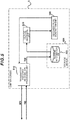
- Fig. 3 is a block diagram illustrating the hardware configuration of the roadside unit 3 and the center server 5.
- the roadside unit 3 comprises a roadside unit control unit 205 and a wireless transmission/reception unit 206.
- the wireless transmission/reception unit 206 performs data communication with the in-vehicle remote monitoring device 20 equipped in the vehicle 2 by sending and receiving wireless signals.
- the roadside unit control unit 205 controls the roadside unit 3.
- the roadside unit control unit 205 is connected to the network 4.
- the roadside unit control unit 205 performs data communication with the center server 5 via the network 4.
- the roadside unit control unit 205 controls the wireless transmission/reception unit 206 and sends information, which was sent from the center server 5, to the vehicle 2, and sends information, which was received from the vehicle 2, to the center server 5.
- the center server 5 comprises a storage device 501, a CPU 502, and a memory unit 503.
- the storage device 501 is, for example, an auxiliary storage device such as an HDD or a flash memory.
- the CPU 502 processes information sent to and received from the roadside unit 3 by reading and executing, for example, predetermined control programs stored in the storage device 501 or the like.
- the memory unit 503 is a main storage device that is used by the CPU 502 upon executing control programs.
- the CPU 502 functionally comprises a transmitted/received information processing unit 510, an incident analysis processing unit 520, and a recovery plan generation unit 530.
- the transmitted/received information processing unit 510, the incident analysis processing unit 520, and the recovery plan generation unit 530 are realized via software based on the control programs executed by the CPU 502.
- the transmitted/received information processing unit 510, the incident analysis processing unit 520, and the recovery plan generation unit 530 will be described later in detail.
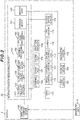
- Fig. 4 is a block diagram illustrating the functional configuration of the in-vehicle remote monitoring device 20.
- the storage device 101 includes a vehicle information DB 171.
- the recovery plan processing unit 160 uses the wireless communication device 105 to communicate with the roadside unit 3, and receives a recovery plan 900 from the center server 5 via the roadside unit 3.
- the received recovery plan 900 is output to the communication control unit 130.
- the recovery plan 900 is information that is sent from the center server 5, in cases where a security incident occurs as a result of any one of the devices in the foregoing control-based network domain, driver assistance-based network domain or information-based network domain encounters a cyberattack, to recover the unit that encountered the incident.
- the recovery plan 900 includes, for example, the backdate order and configuration file of the software running on that device, and update software.
- the incident detection processing unit 120 detects the occurrence of an incident based on the vehicle information stored in the vehicle information DB 171, and the map information 600 stored in the navigation system 119.
- the incident detection processing unit 120 uses the wireless communication device 105 to communicate with the roadside unit 3, and sends incident information 700 related to the detected incident to the center server 5 via the roadside unit 3.
- the incident information 700 includes the location where the incident was detected, software version of the device of the information source when the incident was detected, cause of the incident, and date and time that the incident was detected.
- the incident detection processing unit 120 when the occurrence of an incident is detected, the incident detection processing unit 120 respectively outputs, to the communication control unit 130, the function deactivation unit 140, and the warning processing unit 150, a transfer stop instruction for instructing the stop of information transfer between different networks, an automated driving deactivation instruction for instructing the deactivation of the automated driving of the vehicle 2, and an incident notice for notifying the occurrence of an incident.
- the communication control unit 130 relays the communication between the respective networks connected to the in-vehicle remote monitoring device 20. For example, the communication control unit 130 transfers a brake control instruction sent from the brake control ECU 111 of the driver assistance-based network domain to the brake ECU 107 of the control-based network domain between these networks. Communication between units within the same network and between units within different networks is performed based on the vehicle information packet 800 described later.
- the communication control unit 130 receives the vehicle information packet 800 to be sent and received between the respective units, information included in such packet is added to the vehicle information DB 171 as the vehicle information representing the control state of the vehicle 2.
- the vehicle information DB 171 stores information included in the vehicle information packet 800 as vehicle information in chronological order.
- the communication control unit 130 When the communication control unit 130 receives the recovery plan 900 from the recovery plan processing unit 160, the communication control unit 130 sends the received recovery plan 900 to the destination device. Moreover, when the communication control unit 130 receives a transfer stop instruction from the incident detection processing unit 120, the communication control unit 130 blocks the communication between the respective units belonging to different networks.
- the function deactivation unit 140 When the function deactivation unit 140 receives the automated driving deactivation instruction from the incident detection processing unit 120, the function deactivation unit 140 deactivates the automated driving function of the vehicle 2.
- the function deactivation unit 140 deactivates the automated driving function of the vehicle 2, for example, by instructing the communication control unit 130 to block the transfer of information from the respective units of the driver assistance-based network to the respective units of the control-based network, or instructing the ADAS ECU 110 to deactivate the automated driving function via the communication control unit 130.
- the warning processing unit 150 When the warning processing unit 150 receives an incident notice from the incident detection processing unit 120, the warning processing unit 150 uses the display device 118 and warns the user as the driver of the vehicle 2. The warning processing unit 150 instructs the user to perform a switching operation of switching from automated driving to manual driving by using the user switch 117, for example, by displaying a predetermined screen on the display device 118. When a switching operation is input using the user switch 117, the warning processing unit 150 notifies the incident detection processing unit 120 to such effect.
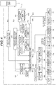
- Fig. 5 is a block diagram illustrating the functional configuration of the center server 5.
- the storage device 501 includes an incident information DB 551.
- the transmitted/received information processing unit 510 sends and receives information to and from the roadside unit 3. For example, the transmitted/received information processing unit 510 receives the incident information 700, which was sent from the vehicle 2, via the roadside unit 3. The transmitted/received information processing unit 510 stores the incident information 700, which was received from the vehicle 2, in the incident information DB 551.
- the incident analysis processing unit 520 analyzes the incident information 700 stored in the incident information DB 551, and notifies the analytical result thereof to the recovery plan generation unit 530.
- the recovery plan generation unit 530 generates the recovery plan 900 corresponding to the incident that occurred in the vehicle 2 based on the analytical result of the incident analysis processing unit 520.
- the transmitted/received information processing unit 510 sends the recovery plan 900 generated by the recovery plan generation unit 530 to the vehicle 2 via the roadside unit 3.
- Fig. 6 is an explanatory diagram illustrating the configuration of the map information 600.
- the map information 600 includes the respective types of information of link ID 601, speed limit 602, direction constraint 603, first latitude information 604, second latitude information 605, first longitude information 606, and second longitude information 607.
- the link ID 601 represents the link ID assigned to each road link. With which road link the map information corresponds is identified based on the value of the link ID 601. Note that the values of the link ID are each pre-set to a unique value for each road link so that they do not mutually overlap.
- the speed limit 602 represents the speed limit that is set to the road link corresponding to the map information.
- the upper limit of the driving speed during the automated driving of the vehicle 2 is set according to the value of the speed limit 602.
- the direction constraint 603 represents the direction of the road link corresponding to the map information.
- the direction constraint 603 is expressed as an angle in which a predetermined direction (for example, magnetic north direction) is 0.
- the first latitude information 604 is a latitude value representing the position of the road link corresponding to the map information.
- the second latitude information 605 is information representing whether the value of the first latitude information 604 indicates the north latitude (N) or the south latitude (S).
- the first longitude information 606 is a longitude value representing the position of the road link corresponding to the map information.
- the second longitude information 607 is information representing whether the value of the first longitude information 606 indicates the east longitude (E) or the west longitude (W).
- Fig. 7 is an explanatory diagram illustrating the configuration of the vehicle information packet 800.
- the vehicle information packet 800 includes the respective types of information of CAN ID 801, control parameter 802, and measurement time 803.
- the CAN ID 801 is information indicating the CAN ID that is set to the source of the vehicle information packet 800. A unique number for each device is pre-set as the CAN ID to the respective units within the network. Each device sets, as the CAN ID 801, information indicating its own CAN ID upon sending the vehicle information packet 800.
- the control parameter 802 is information representing the control value to be used in the control to be performed by the device that received the vehicle information packet 800.
- the control parameter 802 is set with various values according to the content of the control to be performed by the respective units. For example, information such as the accelerator position, the brake pressure, the steering angle, and the engine rpm can be represented with the control parameter 802.
- the control parameter 802 may also include information representing the operational status of the direction indicator 109, and the captured image data of the camera 114.
- the measurement time 803 is information representing the time (time of day) that the vehicle information packet 800 was sent. Upon sending the vehicle information packet 800, each device sets, as the measurement time 803, information indicating the time that the vehicle information packet 800 was sent.
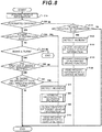
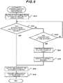
- Fig. 8 is a flowchart of the vehicle information monitoring processing executed by the CPU 102 of the in-vehicle remote monitoring device 20. The processing shown in this flowchart is executed once in predetermined intervals by the CPU 102 of the in-vehicle remote monitoring device 20 mounted in the vehicle 2.
- step S10 the CPU 102 uses the incident detection processing unit 120 to acquire the vehicle information accumulated in the vehicle information DB 171 by reading such vehicle information from the vehicle information DB 171.
- step S20 the CPU 102 uses the incident detection processing unit 120 to determine whether the vehicle 2 is currently engaged in automated driving based on the vehicle information acquired in step S10.
- the CPU 102 advances the processing to step S30, and when the vehicle 2 is not engaged in automated driving; that is, when the user is manually driving the vehicle 2, the CPU 102 advances the processing to step S110.
- step S30 the CPU 102 uses the incident detection processing unit 120 to determine whether the vehicle information acquired in step S10 is violating a predetermined transmission rule. Consequently, the CPU 102 advances the processing to step S70 when it is determined that the vehicle information is violating the transmission rule, and advances the processing to step S40 when it is determined that the vehicle information is not violating the transmission rule.
- the determination of step S30 is performed by confirming whether the value of the CAN ID 801 is included in a pre-registered number list, confirming whether the value of the control parameter 802 is within a pre-set range, and whether the difference between the value of the measurement time 803 and the current time is less than a pre-set threshold.
- the foregoing criterion values that is, the number list of the CAN ID 801, the setting range of the control parameter 802, and the threshold of the difference between the measurement time 803 and the current time are pre-set as transmission rules.
- step S40 the CPU 102 determines whether the vehicle 2 will make a turn based on the vehicle information acquired in step S10 by the incident detection processing unit 120. Consequently, the CPU 102 advances the processing to step S50 when it is determined that the vehicle 2 will make a turn, and ends the vehicle information monitoring processing of Fig. 8 when it is determined that the vehicle 2 will not make a turn. Specifically, for example, it is determined that the vehicle 2 will make a turn when the value of the control parameter 802 in the vehicle information represents a steering angle of a predetermined angle or more. Moreover, whether the vehicle 2 will make a turn may also be determined based on the map information 600 equipped in the navigation system 119.
- whether the vehicle 2 will make a turn is determined by obtaining the direction of the road on which the vehicle 2 is traveling from the map information 600, and comparing such direction with the vehicle information representing the steering angle, position, and acceleration of the vehicle 2.
- the captured images of the camera 114 may also be used.
- Other various methods may also be used for the determination of step S40.
- the expression "make a turn” includes, for example, deviation from the driving lane and a right/left turn at an intersection.
- step S50 the CPU 102 uses the incident detection processing unit 120 to determine whether the direction of the turn to be made by the vehicle 2 is being correctly notified based on the vehicle information acquired in step S10. Consequently, the CPU 102 advances the processing to step S60 when it is determined that the direction of the turn to be made by the vehicle 2 is being correctly notified, and advances the processing to step S70 when it is determined that the direction of the turn to be made by the vehicle 2 is not being correctly notified.
- step S50 can be performed by confirming the operational status of the direction indicator 109 from the value of the control parameter 802 in the vehicle information, and determining whether the direction indicator 109 is correctly indicating the direction of the turn to be made by the vehicle 2 determined in step S40 by the direction indicator 109.
- step S60 the CPU 102 uses the incident detection processing unit 120 to determine whether there is an obstacle which will hinder the making of the turn by the vehicle 2 based on the vehicle information acquired in step S10. Consequently, the CPU 102 advances the processing to step S70 when it is determined that there is an obstacle, and ends the vehicle information monitoring processing of Fig. 8 when it is determined that there is no such obstacle. Specifically, for example, whether another vehicle or an object that will hinder the making of the turn by the vehicle 2 exists around the vehicle 2 is determined based on the vehicle information representing the image information acquired by the camera 114. Consequently, if there is another vehicle or an object that will hinder the making of the turn by the vehicle 2, such other vehicle or object is recognized as an obstacle.
- radar sensors may also be used in substitute for the camera 114, or concurrently with the camera 114.
- step S70 the CPU 102 uses the incident detection processing unit 120 to detect an incident.
- the CPU 102 detects, as an incident that occurred in the vehicle 2, an event such as a violation of the transmission rule by the vehicle information determined in step S30, a notice of an improper direction of making a turn determined in step S50, an existence of an obstacle upon making a turn determined in step S60.
- step S80 the CPU 102 executes the automated driving function deactivation processing for deactivating the automated driving function of the vehicle 2. Details of this automated driving function deactivation processing will be explained later with reference to Fig. 9 .
- step S90 the CPU 102 uses the communication control unit 130 to block the transfer of specific vehicle information to other networks.
- the incident detection processing unit 120 outputs a transfer stop instruction to the communication control unit 130.
- the communication control unit 130 that received the transfer stop instruction from the incident detection processing unit 120 blocks the transfer of the vehicle information including the CAN ID of the respective units belonging to the driver assistance-based network to the other networks.
- step S100 the CPU 102 uses the incident detection processing unit 120 to output the incident information 700 related to the detected incident to the wireless communication device 105, and sends the incident information 700 to the center server 5 via the roadside unit 3.
- step S100 the CPU 102 ends the vehicle information monitoring processing of Fig. 8 .
- step S110 the CPU 102 uses the incident detection processing unit 120 to determine whether the vehicle information acquired in step S10 is violating predetermined transmission rule. Consequently, the CPU 102 advances the processing to step S120 when it is determined that the vehicle information is breaching the transmission rule, and ends the vehicle information monitoring processing of Fig. 8 when it is determined that the vehicle information is not breaching the transmission rule. Note that the determination of step S110 may be performed in the same manner as step S30.
- step S120 the CPU 102 uses the incident detection processing unit 120 to detect an incident.
- the CPU 102 detects the violation of the termination rule by the vehicle information determined in step S110 as an incident that occurred in the vehicle 2.
- step S130 the CPU 102 uses the communication control unit 130 to block the transfer of specific vehicle information to the other networks of such vehicle information in the same manner as step S90.
- step S140 the CPU 102 uses the function deactivation unit 140 to prohibit the operation of the automated driving function in the vehicle 2.
- the incident detection processing unit 120 outputs an automated driving deactivation instruction to the function deactivation unit 140.
- the function deactivation unit 140 that received the automated driving deactivation instruction from the incident detection processing unit 120 for example, prohibits the operation of the automated driving function by instructing the ADAS ECU 110 to prohibit the operation of the automated driving function via the communication control unit 130.
- step S150 the CPU 102 uses the incident detection processing unit 120 to output the incident information 700 related to the detected incident to the wireless communication device 105, and sends the incident information 700 to the center server 5 via the roadside unit 3.
- step S150 the CPU 102 ends the vehicle information monitoring processing of Fig. 8 .
- Fig. 9 is a flowchart of the automated driving function deactivation processing executed in step S80 of Fig. 8 .
- step S210 the CPU 102 uses the warning processing unit 150 to instruct the user as the driver of the vehicle 2 to switch from automated driving to manual driving.
- the incident detection processing unit 120 outputs an incident notice to the warning processing unit 150.
- the warning processing unit 150 that received the incident notice from the incident detection processing unit 120 urges the user to switch from automated driving to manual driving by instructing the display device 118 to display a predetermined screen via the communication control unit 130.
- step S220 the CPU 102 determines whether the control state has been switched from automated driving to manual driving.
- the automated driving function of the ADAS ECU 110 is deactivated as a result of the user performing a predetermined switching operation using the user switch 117 according to the instruction of step S210, it is determined that the control state has been switched from automated driving to manual driving, and the CPU 102 advances the processing to step S260.
- a switching operation is not input using the user switch 117, it is determined that the control state has not been switched from automated driving to manual driving, and the CPU 102 advances the processing to step S230.
- step S230 the CPU 102 determines whether a given period of time, such as 10 seconds, has elapsed from the time that the user was instructed to switch to manual driving in step S210.
- the CPU 102 advances the processing to step S240 if a given period of time has elapsed, and returns to step S220 if a given period of time has not elapsed.
- step S240 the CPU 102 instructs the ADAS ECU 110 to stop the vehicle 2 on a road shoulder.
- the vehicle 2 may be stopped at a location other than the road shoulder so as long as the vehicle 2 can be safely stopped. Consequently, if a predetermined switching operation is not performed using the user switch 117 within a given period of time from the time that the user was instructed to switch to manual driving in step S210, the CPU 102 instructs the ADAS ECU 110 to stop the vehicle 2 at a safe location.
- step S250 the CPU 102 switches the control state of the vehicle 2 from automated driving to manual driving.
- the CPU 102 outputs an instruction for deactivating the automated driving function from the function deactivation unit 140 to the ADAS ECU 110.
- the ADAS ECU 110 that received the foregoing instruction can no longer use the automated driving function as a result of prohibiting the brake control ECU 111, the steering control ECU 112, and the engine control ECU 113 from outputting control instructions related to the acceleration, steering and braking of the vehicle 2.
- step S260 the CPU 102 advances the processing to step S260.
- step S260 the CPU 102 uses the warning processing unit 150 to notify the user that automated driving cannot be used.
- the warning processing unit 150 notifies the user that automated driving cannot be used due to the occurrence of an incident, for example, by causing the display device 118 to display a predetermined message via the communication control unit 130.
- step S270 the CPU 102 uses the function deactivation unit 140 to prohibit the operation of the automated driving function in the vehicle 2.
- the function deactivation unit 140 prohibits the operation of the automated driving function, in the same manner as step S140 of Fig. 8 , for example, by instructing the ADAS ECU 110 to prohibit the operation of the automated driving function via the communication control unit 130.
- the CPU 102 ends the automated driving function deactivation processing of Fig. 9 .
- Fig. 10 is a sequence diagram showing the operation of the overall vehicle information network system 1.
- the center server 5 the in-vehicle remote monitoring device 20, and the respective units within the network respectively execute the processing shown in Fig. 10 .
- step S301 the center server 5 receives the incident information 700 sent from the in-vehicle remote monitoring device 20 via the roadside unit 3, and stores the received incident information 700 in the incident information DB 551.
- step S302 the center server 5 uses the incident analysis processing unit 520 to analyze the incident information 700.
- step S303 the center server 5 uses the recovery plan generation unit 530 to generate the recovery plan 900 including the program correction patch and backdate instruction based on the result of the analysis of the incident information performed in step S302. Subsequently, the center server 5 sends the generated recovery plan 900 to the in-vehicle remote monitoring device 20 via the roadside unit 3.
- step S401 the in-vehicle remote monitoring device 20 receives the vehicle information packet 800 sent from the respective units of the network. Subsequently, the in-vehicle remote monitoring device 20 accumulates the received vehicle information packet 800 in the vehicle information DB 171, and performs inter-domain communication to be transferred to the other networks as needed according to the destinated destination.
- step S402 the in-vehicle remote monitoring device 20 detects the incident by performing the vehicle information monitoring processing of Fig. 8 , and sends the incident information 700 to the center server 5.
- step S403 the in-vehicle remote monitoring device 20 confirms the status of the vehicle 2, and determines whether the vehicle 2 is currently engaged in automated driving.
- step S404 the in-vehicle remote monitoring device 20 instructs the ADAS ECU 110 to deactivate the automated driving function by performing the automated driving function deactivation processing of Fig. 9 .
- step S405 the in-vehicle remote monitoring device 20 receives the recovery plan 900 sent from the center server 5, and implements the recovery plan 900 to the device in which the incident occurred.
- step S501 the respective units of the steering ECU 106, the brake ECU 107, the engine ECU 108, and the direction indicator 109 in the control-based network domain, the respective units of the ADAS ECU 110, the brake control ECU 111, the steering control ECU 112, the engine control ECU 113, the camera 114, the GPS sensor 115, and the acceleration sensor 116 in the driver assistance-based network domain, and the respective units of the user switch 117 and the display device 118 in the information-based network domain send the vehicle information packet 800 to the other units.
- step S502 when the ADAS ECU 110 receives an instruction from the in-vehicle remote monitoring device 20 for deactivating the automated driving function, the ADAS ECU 110 deactivates the automated driving function.
- step S503 the respective units which are affected by the incident that occurred in the network of the vehicle 2 undergo the recovery plan 900 implemented by the in-vehicle remote monitoring device 20.
- 1... vehicle information network system 2... vehicle, 3... roadside unit, 4... network, 5... center server, 20... in-vehicle remote monitoring device, 101... storage device, 102... CPU, 103... memory unit, 105... wireless communication device, 106... steering ECU, 107... brake ECU, 108... engine ECU, 109... direction indicator, 110... ADAS ECU, 111... brake control ECU, 112... steering control ECU, 113... engine control ECU, 114... camera, 115... GPS sensor, 116... acceleration sensor, 117... user switch, 118... display device, 119... navigation system
Landscapes
- Engineering & Computer Science (AREA)
- Automation & Control Theory (AREA)
- Theoretical Computer Science (AREA)
- Physics & Mathematics (AREA)
- Radar, Positioning & Navigation (AREA)
- Remote Sensing (AREA)
- General Physics & Mathematics (AREA)
- Mechanical Engineering (AREA)
- Transportation (AREA)
- General Engineering & Computer Science (AREA)
- Human Computer Interaction (AREA)
- Quality & Reliability (AREA)
- Computing Systems (AREA)
- Mathematical Physics (AREA)
- Software Systems (AREA)
- Computer Security & Cryptography (AREA)
- Computer Hardware Design (AREA)
- Traffic Control Systems (AREA)
- Navigation (AREA)
- Control Of Driving Devices And Active Controlling Of Vehicle (AREA)
- Computer And Data Communications (AREA)
Abstract
Description
- The present invention relates to an in-vehicle device that performs incident monitoring and to an incident monitoring method using such in-vehicle device.
- In recent years, the technology of realizing driving safety support systems and automated driving systems of vehicles by acquiring various types of information in a vehicle through communication between electronic control units (ECUs) equipped in the vehicle and external information communication equipment, and using the acquired information, is becoming popular. With this kind of technology, because the constant connection of the ECUs and the external information communication equipment and the use of general-purpose devices and general-purpose programs in the information communication equipment are advancing, the risk of vehicles becoming the target of cyberattacks is increasing. If a vehicle encounters a cyberattack and goes out of control, human damage and property damage will be extensive, and the social impact will be enormous. Thus, if there is a sign of a cyberattack (cyber incident; hereinafter simply referred to as an "incident") against the ECU manufacturer or automobile manufacturer, there are needs for promptly detecting such as an incident and placing the vehicle in a safe state, and minimizing the consequential damage.
- In relation to the anomaly detection of vehicles, for instance, known is the technology described in
PTL 1. The vehicle fault diagnostic device described inPTL 1 performs the fault diagnosis of a vehicle by comparing the vehicle drive information acquired from the vehicle and the external environment information acquired from a recognizing means which recognizes the surrounding environment, and determining that an anomaly has occurred in the vehicle when the vehicle drive information deviates at a predetermined level or more from a general drive pattern of the vehicle according to the surrounding environment. - [PTL 1] Japanese Unexamined Patent Application Publication No.
2007-161044 - Nevertheless, with the technology described in
PTL 1, because the anomaly of a vehicle is determined by comparing the vehicle drive information acquired from the vehicle and a general drive pattern of the vehicle, it is not possible to determine an anomaly if the vehicle is driving in a manner that is close to a general drive pattern even if an incident has occurred. Accordingly, it is not possible to detect an incident that occurred in a vehicle reliably and quickly. - The in-vehicle device according to the present invention is to be mounted on a vehicle capable of automated driving, and comprises an incident detection processing unit which acquires vehicle information representing a control state of the vehicle, and detects an incident that occurred in the vehicle based on the vehicle information. The incident monitoring method according to the present invention is a method in an in-vehicle device mounted on a vehicle capable of automated driving, and comprises a step of acquiring vehicle information representing a control state of the vehicle, and a step of detecting an incident that occurred in the vehicle based on the vehicle information.
- According to the present invention, an incident that occurred in a vehicle can be detected reliably and quickly.
-
- [
Fig. 1 ]
Fig. 1 is a configuration diagram of the vehicle information network system according to an embodiment of the present invention. - [
Fig. 2 ]
Fig. 2 is a block diagram illustrating the hardware configuration of the vehicle and the in-vehicle remote monitoring device. - [
Fig. 3 ]
Fig. 3 is a block diagram illustrating the hardware configuration of the roadside unit and the center server. - [
Fig. 4 ]
Fig. 4 is a block diagram illustrating the functional configuration of the in-vehicle remote monitoring device. - [
Fig. 5 ]
Fig. 5 is a block diagram illustrating the functional configuration of the center server. - [
Fig. 6 ]
Fig. 6 is an explanatory diagram illustrating the configuration of the map information. - [
Fig. 7 ]
Fig. 7 is an explanatory diagram illustrating the configuration of the in-vehicle information packet. - [
Fig. 8 ]
Fig. 8 is a flowchart of the vehicle information monitoring processing executed by the in-vehicle remote monitoring device. - [
Fig. 9 ]
Fig. 9 is a flowchart of the automated driving function deactivation processing. - [
Fig. 10 ]
Fig. 10 is a sequence diagram of the vehicle communication network system. - An embodiment of the present invention is now explained with reference to
Fig. 1 to Fig. 10 .Fig. 1 is a configuration diagram of the vehicle information network system according to an embodiment of the present invention. The vehicleinformation network system 1 shown inFig. 1 includes avehicle 2, aroadside unit 3, anetwork 4, and acenter server 5. - The
vehicle 2 is equipped with an in-vehicleremote monitoring device 20. Aroadside unit 3 is fixed and installed at a predetermined site on a roadside of the road that thevehicle 2 is traveling on. Theroadside unit 3 and thecenter server 5 are mutually connected via thenetwork 4. Thecenter server 5 performs data communication with the in-vehicleremote monitoring device 20 via thenetwork 4 and theroadside unit 3. - Note that the vehicle
information network system 1 may include a plurality ofvehicles 2 each mounted with an in-vehicleremote monitoring device 20. Moreover, a plurality ofroadside units 3 may each be installed at different sites. In the ensuing explanation, the operation of the in-vehicleremote monitoring device 20 mounted on onevehicle 2 will be mainly explained. -
Fig. 2 is a block diagram illustrating the hardware configuration of thevehicle 2 and the in-vehicleremote monitoring device 20. Thevehicle 2 comprises an in-vehicleremote monitoring device 20, and awireless communication device 105, asteering ECU 106, a brake ECU 107, an engine ECU 108, adirection indicator 109, an ADAS ECU 110, a brake control ECU 111, a steering control ECU 112, anengine control ECU 113, acamera 114, aGPS sensor 115, anacceleration sensor 116, auser switch 117, adisplay device 118, and anavigation system 119 which are respectively connected to the in-vehicleremote monitoring device 20. - The
steering ECU 106, thebrake ECU 107, the engine ECU 108, and thedirection indicator 109 are units for performing the driving control of thevehicle 2, and configure a network by being mutually connected. In the ensuing explanation, this network is hereinafter referred to as the "control-based network domain". The ADAS ECU 110, the brake control ECU 111, the steering control ECU 112, the engine control ECU 113, thecamera 114, theGPS sensor 115, and theacceleration sensor 116 are units for performing the driver assistance or automated driving of thevehicle 2, and configure a network by being mutually connected. In the ensuing explanation, this network is hereinafter referred to as the "driver assistance-based network domain". Theuser switch 117, thedisplay device 118, and thenavigation system 119 are units for providing a user interface to the driver of thevehicle 2, and configure a network by being mutually connected. In the ensuing explanation, this network is hereinafter referred to as the "information-based network domain". In other words, the in-vehicleremote monitoring device 20 is connected to the control-based network domain, the driver assistance-based network domain, and the information-based network domain, and perform data communication with the respective units within these networks. - In each of the foregoing networks, the respective units within the same network can directly perform data communication without going through the in-vehicle
remote monitoring device 20. For example, communication for performing the driving control of thevehicle 2 is performed in the control-based network domain. Communication for the driver assistance or automated driving of thevehicle 2 is performed in the driver assistance-based network domain. Communication for the user interface to be provided to the driver of thevehicle 2 is performed in the information-based network domain. Meanwhile, data communication between units belonging to different networks is performed via the in-vehicleremote monitoring device 20. - The
wireless communication device 105 is connected to the in-vehicleremote monitoring device 20, and performs wireless communication with theroadside unit 3. The in-vehicleremote monitoring device 20 performs data communication with theroadside unit 3 based on wireless communication via thewireless communication device 105. - The steering
ECU 106 is a unit for performing the traveling direction control by controlling the steering mechanism of the vehicle according to the steering operation of the driver of thevehicle 2 or the steering control instruction sent from thesteering control ECU 112. Thebrake ECU 107 is a unit for performing the deceleration control by controlling the brake of thevehicle 2 according the brake operation of the driver of thevehicle 2 or the brake control instruction sent from thebrake control ECU 111. Theengine ECU 108 is a unit for performing the speed control by controlling the engine of thevehicle 2 according to the running state of thevehicle 2 or the engine control instruction sent from theengine control ECU 113. Thedirection indicator 109 is a unit for lighting the signal provided to thevehicle 2 and notifying the other vehicles nearby, when thevehicle 2 is to make a turn, of the direction of such turn according to the direction instruction operation of the driver of thevehicle 2 or the direction instruction order sent from theADAS ECU 110. The driving control of thevehicle 2 is performed based on these units. - The
ADAS ECU 110 is a unit for determining the acceleration, deceleration, or stop of thevehicle 2 based on internal and external information of thevehicle 2, and realizing the automated driving or driver assistance service of thevehicle 2 by using the determination result thereof. TheADAS ECU 110 determines the behavior of thevehicle 2 by referring to the external images acquired from thecamera 114, the position of thevehicle 2 acquired from theGPS sensor 115, the acceleration of thevehicle 2 acquired from theacceleration sensor 116, and the peripheral map information of thevehicle 2 retained by thenavigation system 119. Subsequently, theADAS ECU 110 instructs thebrake control ECU 111, thesteering control ECU 112, and theengine control ECU 113 to respectively output control instructions according to the determined behavior of thevehicle 2. TheADAS ECU 110 thereby automatically performs all operations of acceleration, steering and braking of thevehicle 2, and realizes the automated driving function of thevehicle 2. - A user as the driver of the
vehicle 2 can cause thevehicle 2 to automatically drive to the intended destination without having to perform driving operations by using the automated driving function of theADAS ECU 110. For example, when thevehicle 2 is traveling to the destination while maintaining the same driving lane, theADAS ECU 110 confirms whether there is any obstacle in front of and behind thevehicle 2 based on the external images acquired from thecamera 114. Note that radar sensors (not shown) may also be used in substitute for thecamera 114. Moreover, theADAS ECU 110 determines the traveling direction and the driving speed of thevehicle 2 according to the shape of the driving lane based on the map information acquired from thenavigation system 119, and respectively sends, to thebrake control ECU 111, thesteering control ECU 112, and theengine control ECU 113, vehicle information including the control parameters according to the foregoing values. It is thereby possible to cause thevehicle 2 to automatically drive along the driving lane. Furthermore, for example, when thevehicle 2 is to change lanes while performing automated driving, theADAS ECU 110 controls the operation of thedirection indicator 109 and lights thedirection indicator 109 in the direction of making the lane change. Moreover, theADAS ECU 110 confirms the existence of obstacles on the new lane to be used and determines the behavior of thevehicle 2 upon making the lane change based on the external images acquired from thecamera 114, and respectively sends, to thebrake control ECU 111, thesteering control ECU 112, and theengine control ECU 113, vehicle information including the control parameters according to the foregoing values. It is thereby possible to cause thevehicle 2 to automatically change lanes. - The
brake control ECU 111 is a unit which sends a brake control instruction, including the braking strength, to thebrake ECU 107 according to the instruction of theADAS ECU 110. Thesteering control ECU 112 is a unit which sends a steering control instruction, including the steering operation angle, to thesteering ECU 106 according to the instruction of theADAS ECU 110. Theengine control ECU 113 is a unit which sends an engine control instruction, including the rpm of the engine, to theengine ECU 108 according to the instruction of theADAS ECU 110. Thecamera 114 is a unit which outputs, to theADAS ECU 110, images that captured the periphery of thevehicle 2. TheGPS sensor 115 is a positioning unit which receives signals from a satellite and determines the position of thevehicle 2. Theacceleration sensor 116 is a unit which detects the acceleration of thevehicle 2 in the front-back direction and the left-right direction. The driver assistance and automated driving of thevehicle 2 are performed based on these units. - The
user switch 117 is a unit which detects a predetermined input operation of the driver of thevehicle 2. A user as the driver of thevehicle 2 uses theuser switch 117, for example, upon switching the automated driving or the driver assistance function of thevehicle 2 from a disabled state to an enabled state, or from an enabled state to a disabled state. Thedisplay device 118 is, for example, a liquid crystal monitor or the like, and displays various types of information to the driver. For example, when thevehicle 2 is performing automated driving or driver assistance, the driver can comprehend the status of thevehicle 2 by displaying a message on the display device 18 to the effect that such function has been enabled. Thenavigation system 119 is a unit which retains map information such as the road shape, and provides map information around thevehicle 2 according to a request from the user or theADAS ECU 110. The user interface is provided to the driver of thevehicle 2 based on these units. - The in-vehicle
remote monitoring device 20 comprises astorage device 101, aCPU 102, and amemory unit 103. Thestorage device 101 is, for example, an auxiliary storage device such as an HDD or a flash memory. TheCPU 102 controls the in-vehicleremote monitoring device 20 by reading and executing, for example, predetermined control programs stored in thestorage device 101 or the like. - The
memory unit 103 is a main storage device that is used by theCPU 102 upon executing control programs. - The
CPU 102 functionally comprises an incidentdetection processing unit 120, acommunication control unit 130, afunction deactivation unit 140, awarning processing unit 150, and a recoveryplan processing unit 160. In other words, the incidentdetection processing unit 120, thecommunication control unit 130, thefunction deactivation unit 140, thewarning processing unit 150, and the recoveryplan processing unit 160 are realized via software based on the control programs executed by theCPU 102. The incidentdetection processing unit 120, thecommunication control unit 130, thefunction deactivation unit 140, thewarning processing unit 150, and the recoveryplan processing unit 160 will be described later in detail. - Note that the incident
detection processing unit 120, thecommunication control unit 130, thefunction deactivation unit 140, thewarning processing unit 150, and the recoveryplan processing unit 160 may also be respectively configured, for example, from an electronic circuit such as an FPGA capable of realizing functions that are equivalent to those of theCPU 102. -
Fig. 3 is a block diagram illustrating the hardware configuration of theroadside unit 3 and thecenter server 5. Theroadside unit 3 comprises a roadsideunit control unit 205 and a wireless transmission/reception unit 206. - The wireless transmission/
reception unit 206 performs data communication with the in-vehicleremote monitoring device 20 equipped in thevehicle 2 by sending and receiving wireless signals. The roadsideunit control unit 205 controls theroadside unit 3. The roadsideunit control unit 205 is connected to thenetwork 4. The roadsideunit control unit 205 performs data communication with thecenter server 5 via thenetwork 4. The roadsideunit control unit 205 controls the wireless transmission/reception unit 206 and sends information, which was sent from thecenter server 5, to thevehicle 2, and sends information, which was received from thevehicle 2, to thecenter server 5. - The
center server 5 comprises astorage device 501, aCPU 502, and amemory unit 503. Thestorage device 501 is, for example, an auxiliary storage device such as an HDD or a flash memory. TheCPU 502 processes information sent to and received from theroadside unit 3 by reading and executing, for example, predetermined control programs stored in thestorage device 501 or the like. Thememory unit 503 is a main storage device that is used by theCPU 502 upon executing control programs. - The
CPU 502 functionally comprises a transmitted/receivedinformation processing unit 510, an incidentanalysis processing unit 520, and a recoveryplan generation unit 530. In other words, the transmitted/receivedinformation processing unit 510, the incidentanalysis processing unit 520, and the recoveryplan generation unit 530 are realized via software based on the control programs executed by theCPU 502. The transmitted/receivedinformation processing unit 510, the incidentanalysis processing unit 520, and the recoveryplan generation unit 530 will be described later in detail. - The functional configuration of the in-vehicle
remote monitoring device 20 and thecenter server 5 is now explained. -
Fig. 4 is a block diagram illustrating the functional configuration of the in-vehicleremote monitoring device 20. Thestorage device 101 includes avehicle information DB 171. - The recovery
plan processing unit 160 uses thewireless communication device 105 to communicate with theroadside unit 3, and receives arecovery plan 900 from thecenter server 5 via theroadside unit 3. The receivedrecovery plan 900 is output to thecommunication control unit 130. Therecovery plan 900 is information that is sent from thecenter server 5, in cases where a security incident occurs as a result of any one of the devices in the foregoing control-based network domain, driver assistance-based network domain or information-based network domain encounters a cyberattack, to recover the unit that encountered the incident. Therecovery plan 900 includes, for example, the backdate order and configuration file of the software running on that device, and update software. - The incident
detection processing unit 120 detects the occurrence of an incident based on the vehicle information stored in thevehicle information DB 171, and themap information 600 stored in thenavigation system 119. When the occurrence of an incident is detected, the incidentdetection processing unit 120 uses thewireless communication device 105 to communicate with theroadside unit 3, and sendsincident information 700 related to the detected incident to thecenter server 5 via theroadside unit 3. Theincident information 700 includes the location where the incident was detected, software version of the device of the information source when the incident was detected, cause of the incident, and date and time that the incident was detected. Moreover, when the occurrence of an incident is detected, the incidentdetection processing unit 120 respectively outputs, to thecommunication control unit 130, thefunction deactivation unit 140, and thewarning processing unit 150, a transfer stop instruction for instructing the stop of information transfer between different networks, an automated driving deactivation instruction for instructing the deactivation of the automated driving of thevehicle 2, and an incident notice for notifying the occurrence of an incident. - The
communication control unit 130 relays the communication between the respective networks connected to the in-vehicleremote monitoring device 20. For example, thecommunication control unit 130 transfers a brake control instruction sent from thebrake control ECU 111 of the driver assistance-based network domain to thebrake ECU 107 of the control-based network domain between these networks. Communication between units within the same network and between units within different networks is performed based on thevehicle information packet 800 described later. When thecommunication control unit 130 receives thevehicle information packet 800 to be sent and received between the respective units, information included in such packet is added to thevehicle information DB 171 as the vehicle information representing the control state of thevehicle 2. In other words, thevehicle information DB 171 stores information included in thevehicle information packet 800 as vehicle information in chronological order. - When the
communication control unit 130 receives therecovery plan 900 from the recoveryplan processing unit 160, thecommunication control unit 130 sends the receivedrecovery plan 900 to the destination device. Moreover, when thecommunication control unit 130 receives a transfer stop instruction from the incidentdetection processing unit 120, thecommunication control unit 130 blocks the communication between the respective units belonging to different networks. - When the
function deactivation unit 140 receives the automated driving deactivation instruction from the incidentdetection processing unit 120, thefunction deactivation unit 140 deactivates the automated driving function of thevehicle 2. Thefunction deactivation unit 140 deactivates the automated driving function of thevehicle 2, for example, by instructing thecommunication control unit 130 to block the transfer of information from the respective units of the driver assistance-based network to the respective units of the control-based network, or instructing theADAS ECU 110 to deactivate the automated driving function via thecommunication control unit 130. - When the
warning processing unit 150 receives an incident notice from the incidentdetection processing unit 120, thewarning processing unit 150 uses thedisplay device 118 and warns the user as the driver of thevehicle 2. Thewarning processing unit 150 instructs the user to perform a switching operation of switching from automated driving to manual driving by using theuser switch 117, for example, by displaying a predetermined screen on thedisplay device 118. When a switching operation is input using theuser switch 117, thewarning processing unit 150 notifies the incidentdetection processing unit 120 to such effect. -
Fig. 5 is a block diagram illustrating the functional configuration of thecenter server 5. Thestorage device 501 includes anincident information DB 551. - The transmitted/received
information processing unit 510 sends and receives information to and from theroadside unit 3. For example, the transmitted/receivedinformation processing unit 510 receives theincident information 700, which was sent from thevehicle 2, via theroadside unit 3. The transmitted/receivedinformation processing unit 510 stores theincident information 700, which was received from thevehicle 2, in theincident information DB 551. - The incident
analysis processing unit 520 analyzes theincident information 700 stored in theincident information DB 551, and notifies the analytical result thereof to the recoveryplan generation unit 530. - The recovery
plan generation unit 530 generates therecovery plan 900 corresponding to the incident that occurred in thevehicle 2 based on the analytical result of the incidentanalysis processing unit 520. The transmitted/receivedinformation processing unit 510 sends therecovery plan 900 generated by the recoveryplan generation unit 530 to thevehicle 2 via theroadside unit 3. -
Fig. 6 is an explanatory diagram illustrating the configuration of themap information 600. Themap information 600 includes the respective types of information oflink ID 601,speed limit 602,direction constraint 603,first latitude information 604,second latitude information 605,first longitude information 606, andsecond longitude information 607. - The
link ID 601 represents the link ID assigned to each road link. With which road link the map information corresponds is identified based on the value of thelink ID 601. Note that the values of the link ID are each pre-set to a unique value for each road link so that they do not mutually overlap. - The
speed limit 602 represents the speed limit that is set to the road link corresponding to the map information. The upper limit of the driving speed during the automated driving of thevehicle 2 is set according to the value of thespeed limit 602. - The
direction constraint 603 represents the direction of the road link corresponding to the map information. Thedirection constraint 603 is expressed as an angle in which a predetermined direction (for example, magnetic north direction) is 0. - The
first latitude information 604 is a latitude value representing the position of the road link corresponding to the map information. Thesecond latitude information 605 is information representing whether the value of thefirst latitude information 604 indicates the north latitude (N) or the south latitude (S). Thefirst longitude information 606 is a longitude value representing the position of the road link corresponding to the map information. Thesecond longitude information 607 is information representing whether the value of thefirst longitude information 606 indicates the east longitude (E) or the west longitude (W). -
Fig. 7 is an explanatory diagram illustrating the configuration of thevehicle information packet 800. Thevehicle information packet 800 includes the respective types of information ofCAN ID 801,control parameter 802, andmeasurement time 803. - The
CAN ID 801 is information indicating the CAN ID that is set to the source of thevehicle information packet 800. A unique number for each device is pre-set as the CAN ID to the respective units within the network. Each device sets, as theCAN ID 801, information indicating its own CAN ID upon sending thevehicle information packet 800. - The
control parameter 802 is information representing the control value to be used in the control to be performed by the device that received thevehicle information packet 800. Thecontrol parameter 802 is set with various values according to the content of the control to be performed by the respective units. For example, information such as the accelerator position, the brake pressure, the steering angle, and the engine rpm can be represented with thecontrol parameter 802. Moreover, thecontrol parameter 802 may also include information representing the operational status of thedirection indicator 109, and the captured image data of thecamera 114. - The
measurement time 803 is information representing the time (time of day) that thevehicle information packet 800 was sent. Upon sending thevehicle information packet 800, each device sets, as themeasurement time 803, information indicating the time that thevehicle information packet 800 was sent. -
Fig. 8 is a flowchart of the vehicle information monitoring processing executed by theCPU 102 of the in-vehicleremote monitoring device 20. The processing shown in this flowchart is executed once in predetermined intervals by theCPU 102 of the in-vehicleremote monitoring device 20 mounted in thevehicle 2. - In step S10, the
CPU 102 uses the incidentdetection processing unit 120 to acquire the vehicle information accumulated in thevehicle information DB 171 by reading such vehicle information from thevehicle information DB 171. Here, it is preferable to exclude any vehicle information that has been previously acquired in the past processing, and extract and acquire only vehicle information that has not yet been acquired. - In step S20, the
CPU 102 uses the incidentdetection processing unit 120 to determine whether thevehicle 2 is currently engaged in automated driving based on the vehicle information acquired in step S10. When thevehicle 2 is engaged in automated driving, theCPU 102 advances the processing to step S30, and when thevehicle 2 is not engaged in automated driving; that is, when the user is manually driving thevehicle 2, theCPU 102 advances the processing to step S110. - In step S30, the
CPU 102 uses the incidentdetection processing unit 120 to determine whether the vehicle information acquired in step S10 is violating a predetermined transmission rule. Consequently, theCPU 102 advances the processing to step S70 when it is determined that the vehicle information is violating the transmission rule, and advances the processing to step S40 when it is determined that the vehicle information is not violating the transmission rule. Specifically, for example, the determination of step S30 is performed by confirming whether the value of theCAN ID 801 is included in a pre-registered number list, confirming whether the value of thecontrol parameter 802 is within a pre-set range, and whether the difference between the value of themeasurement time 803 and the current time is less than a pre-set threshold. Note that, in the in-vehicleremote monitoring device 20, the foregoing criterion values; that is, the number list of theCAN ID 801, the setting range of thecontrol parameter 802, and the threshold of the difference between themeasurement time 803 and the current time are pre-set as transmission rules. - In step S40, the
CPU 102 determines whether thevehicle 2 will make a turn based on the vehicle information acquired in step S10 by the incidentdetection processing unit 120. Consequently, theCPU 102 advances the processing to step S50 when it is determined that thevehicle 2 will make a turn, and ends the vehicle information monitoring processing ofFig. 8 when it is determined that thevehicle 2 will not make a turn. Specifically, for example, it is determined that thevehicle 2 will make a turn when the value of thecontrol parameter 802 in the vehicle information represents a steering angle of a predetermined angle or more. Moreover, whether thevehicle 2 will make a turn may also be determined based on themap information 600 equipped in thenavigation system 119. For example, whether thevehicle 2 will make a turn is determined by obtaining the direction of the road on which thevehicle 2 is traveling from themap information 600, and comparing such direction with the vehicle information representing the steering angle, position, and acceleration of thevehicle 2. Furthermore, here, the captured images of thecamera 114 may also be used. Other various methods may also be used for the determination of step S40. Note that the expression "make a turn" includes, for example, deviation from the driving lane and a right/left turn at an intersection. - In step S50, the
CPU 102 uses the incidentdetection processing unit 120 to determine whether the direction of the turn to be made by thevehicle 2 is being correctly notified based on the vehicle information acquired in step S10. Consequently, theCPU 102 advances the processing to step S60 when it is determined that the direction of the turn to be made by thevehicle 2 is being correctly notified, and advances the processing to step S70 when it is determined that the direction of the turn to be made by thevehicle 2 is not being correctly notified. Specifically, for example, the determination of step S50 can be performed by confirming the operational status of thedirection indicator 109 from the value of thecontrol parameter 802 in the vehicle information, and determining whether thedirection indicator 109 is correctly indicating the direction of the turn to be made by thevehicle 2 determined in step S40 by thedirection indicator 109. - In step S60, the
CPU 102 uses the incidentdetection processing unit 120 to determine whether there is an obstacle which will hinder the making of the turn by thevehicle 2 based on the vehicle information acquired in step S10. Consequently, theCPU 102 advances the processing to step S70 when it is determined that there is an obstacle, and ends the vehicle information monitoring processing ofFig. 8 when it is determined that there is no such obstacle. Specifically, for example, whether another vehicle or an object that will hinder the making of the turn by thevehicle 2 exists around thevehicle 2 is determined based on the vehicle information representing the image information acquired by thecamera 114. Consequently, if there is another vehicle or an object that will hinder the making of the turn by thevehicle 2, such other vehicle or object is recognized as an obstacle. Here, radar sensors (not shown) may also be used in substitute for thecamera 114, or concurrently with thecamera 114. - In step S70, the
CPU 102 uses the incidentdetection processing unit 120 to detect an incident. In other words, theCPU 102 detects, as an incident that occurred in thevehicle 2, an event such as a violation of the transmission rule by the vehicle information determined in step S30, a notice of an improper direction of making a turn determined in step S50, an existence of an obstacle upon making a turn determined in step S60. - In step S80, the
CPU 102 executes the automated driving function deactivation processing for deactivating the automated driving function of thevehicle 2. Details of this automated driving function deactivation processing will be explained later with reference toFig. 9 . - In step S90, the
CPU 102 uses thecommunication control unit 130 to block the transfer of specific vehicle information to other networks. Here, the incidentdetection processing unit 120 outputs a transfer stop instruction to thecommunication control unit 130. Thecommunication control unit 130 that received the transfer stop instruction from the incidentdetection processing unit 120, for example, blocks the transfer of the vehicle information including the CAN ID of the respective units belonging to the driver assistance-based network to the other networks. - In step S100, the
CPU 102 uses the incidentdetection processing unit 120 to output theincident information 700 related to the detected incident to thewireless communication device 105, and sends theincident information 700 to thecenter server 5 via theroadside unit 3. After executing step S100, theCPU 102 ends the vehicle information monitoring processing ofFig. 8 . - When the
vehicle 2 is not engaged in automated driving, in step S110, theCPU 102 uses the incidentdetection processing unit 120 to determine whether the vehicle information acquired in step S10 is violating predetermined transmission rule. Consequently, theCPU 102 advances the processing to step S120 when it is determined that the vehicle information is breaching the transmission rule, and ends the vehicle information monitoring processing ofFig. 8 when it is determined that the vehicle information is not breaching the transmission rule. Note that the determination of step S110 may be performed in the same manner as step S30. - In step S120, the
CPU 102 uses the incidentdetection processing unit 120 to detect an incident. In other words, theCPU 102 detects the violation of the termination rule by the vehicle information determined in step S110 as an incident that occurred in thevehicle 2. - In step S130, the
CPU 102 uses thecommunication control unit 130 to block the transfer of specific vehicle information to the other networks of such vehicle information in the same manner as step S90. - In step S140, the
CPU 102 uses thefunction deactivation unit 140 to prohibit the operation of the automated driving function in thevehicle 2. Here, the incidentdetection processing unit 120 outputs an automated driving deactivation instruction to thefunction deactivation unit 140. Thefunction deactivation unit 140 that received the automated driving deactivation instruction from the incidentdetection processing unit 120, for example, prohibits the operation of the automated driving function by instructing theADAS ECU 110 to prohibit the operation of the automated driving function via thecommunication control unit 130. - In step S150, the
CPU 102 uses the incidentdetection processing unit 120 to output theincident information 700 related to the detected incident to thewireless communication device 105, and sends theincident information 700 to thecenter server 5 via theroadside unit 3. After executing step S150, theCPU 102 ends the vehicle information monitoring processing ofFig. 8 . -
Fig. 9 is a flowchart of the automated driving function deactivation processing executed in step S80 ofFig. 8 . - In step S210, the
CPU 102 uses thewarning processing unit 150 to instruct the user as the driver of thevehicle 2 to switch from automated driving to manual driving. Here, the incidentdetection processing unit 120 outputs an incident notice to thewarning processing unit 150. Thewarning processing unit 150 that received the incident notice from the incidentdetection processing unit 120, for example, urges the user to switch from automated driving to manual driving by instructing thedisplay device 118 to display a predetermined screen via thecommunication control unit 130. - In step S220, the
CPU 102 determines whether the control state has been switched from automated driving to manual driving. When the automated driving function of theADAS ECU 110 is deactivated as a result of the user performing a predetermined switching operation using theuser switch 117 according to the instruction of step S210, it is determined that the control state has been switched from automated driving to manual driving, and theCPU 102 advances the processing to step S260. Meanwhile, when a switching operation is not input using theuser switch 117, it is determined that the control state has not been switched from automated driving to manual driving, and theCPU 102 advances the processing to step S230. - In step S230, the
CPU 102 determines whether a given period of time, such as 10 seconds, has elapsed from the time that the user was instructed to switch to manual driving in step S210. TheCPU 102 advances the processing to step S240 if a given period of time has elapsed, and returns to step S220 if a given period of time has not elapsed. - In step S240, the
CPU 102 instructs theADAS ECU 110 to stop thevehicle 2 on a road shoulder. Note that thevehicle 2 may be stopped at a location other than the road shoulder so as long as thevehicle 2 can be safely stopped. Consequently, if a predetermined switching operation is not performed using theuser switch 117 within a given period of time from the time that the user was instructed to switch to manual driving in step S210, theCPU 102 instructs theADAS ECU 110 to stop thevehicle 2 at a safe location. - In step S250, the
CPU 102 switches the control state of thevehicle 2 from automated driving to manual driving. For example, theCPU 102 outputs an instruction for deactivating the automated driving function from thefunction deactivation unit 140 to theADAS ECU 110. TheADAS ECU 110 that received the foregoing instruction can no longer use the automated driving function as a result of prohibiting thebrake control ECU 111, thesteering control ECU 112, and theengine control ECU 113 from outputting control instructions related to the acceleration, steering and braking of thevehicle 2. After executing step S250, theCPU 102 advances the processing to step S260. - In step S260, the
CPU 102 uses thewarning processing unit 150 to notify the user that automated driving cannot be used. Here, thewarning processing unit 150 notifies the user that automated driving cannot be used due to the occurrence of an incident, for example, by causing thedisplay device 118 to display a predetermined message via thecommunication control unit 130. - In step S270, the
CPU 102 uses thefunction deactivation unit 140 to prohibit the operation of the automated driving function in thevehicle 2. Here, thefunction deactivation unit 140 prohibits the operation of the automated driving function, in the same manner as step S140 ofFig. 8 , for example, by instructing theADAS ECU 110 to prohibit the operation of the automated driving function via thecommunication control unit 130. After executing step S270, theCPU 102 ends the automated driving function deactivation processing ofFig. 9 . - The operation of the overall vehicle
information network system 1 is now explained.Fig. 10 is a sequence diagram showing the operation of the overall vehicleinformation network system 1. In the vehicleinformation network system 1, thecenter server 5, the in-vehicleremote monitoring device 20, and the respective units within the network respectively execute the processing shown inFig. 10 . - In step S301, the
center server 5 receives theincident information 700 sent from the in-vehicleremote monitoring device 20 via theroadside unit 3, and stores the receivedincident information 700 in theincident information DB 551. - In step S302, the
center server 5 uses the incidentanalysis processing unit 520 to analyze theincident information 700. Here, for example, the location where an anomaly occurred in thevehicle 2 is identified and the cause thereof is analyzed. - In step S303, the
center server 5 uses the recoveryplan generation unit 530 to generate therecovery plan 900 including the program correction patch and backdate instruction based on the result of the analysis of the incident information performed in step S302. Subsequently, thecenter server 5 sends the generatedrecovery plan 900 to the in-vehicleremote monitoring device 20 via theroadside unit 3. - In step S401, the in-vehicle
remote monitoring device 20 receives thevehicle information packet 800 sent from the respective units of the network. Subsequently, the in-vehicleremote monitoring device 20 accumulates the receivedvehicle information packet 800 in thevehicle information DB 171, and performs inter-domain communication to be transferred to the other networks as needed according to the destinated destination. - When an incident occurs, in step S402, the in-vehicle
remote monitoring device 20 detects the incident by performing the vehicle information monitoring processing ofFig. 8 , and sends theincident information 700 to thecenter server 5. - In step S403, the in-vehicle
remote monitoring device 20 confirms the status of thevehicle 2, and determines whether thevehicle 2 is currently engaged in automated driving. - When it is determined in step S403 that the
vehicle 2 is currently engaged in automated driving, in step S404, the in-vehicleremote monitoring device 20 instructs theADAS ECU 110 to deactivate the automated driving function by performing the automated driving function deactivation processing ofFig. 9 . - In step S405, the in-vehicle
remote monitoring device 20 receives therecovery plan 900 sent from thecenter server 5, and implements therecovery plan 900 to the device in which the incident occurred. - In step S501, the respective units of the
steering ECU 106, thebrake ECU 107, theengine ECU 108, and thedirection indicator 109 in the control-based network domain, the respective units of theADAS ECU 110, thebrake control ECU 111, thesteering control ECU 112, theengine control ECU 113, thecamera 114, theGPS sensor 115, and theacceleration sensor 116 in the driver assistance-based network domain, and the respective units of theuser switch 117 and thedisplay device 118 in the information-based network domain send thevehicle information packet 800 to the other units. - In step S502, when the
ADAS ECU 110 receives an instruction from the in-vehicleremote monitoring device 20 for deactivating the automated driving function, theADAS ECU 110 deactivates the automated driving function. - In step S503, the respective units which are affected by the incident that occurred in the network of the
vehicle 2 undergo therecovery plan 900 implemented by the in-vehicleremote monitoring device 20. - According to an embodiment of the present invention explained above, the following effects are yielded.
- (1) An in-vehicle
remote monitoring device 20 is mounted on avehicle 2 capable of automated driving, and comprises an incidentdetection processing unit 120 which acquires vehicle information representing a control state of thevehicle 2, and detects an incident that occurred in thevehicle 2 based on the acquired vehicle information. As a result of adopting the foregoing configuration, an incident that occurred in thevehicle 2 can be detected reliably and quickly. - (2) The incident
detection processing unit 120 detects the incident based on the vehicle in while thevehicle 2 is engaged in automated driving. Specifically, the incidentdetection processing unit 120 determines whether the vehicle information is violating a predetermined transmission rule (step S30), and detects the incident upon determining that the vehicle information is violating the transmission rule (step S70). Moreover, the incidentdetection processing unit 120 determines, when thevehicle 2 is to make a turn, whether adirection indicator 109 is indicating a direction of the turn to be made by the vehicle based on the vehicle information including information related to an operational status of the direction indicator 109 (step S50), and detects the incident upon determining that thedirection indicator 109 is not indicating the direction of the turn to be made by the vehicle (step S70). Moreover, the incidentdetection processing unit 120 determines, when thevehicle 2 is to make a turn, whether an obstacle which will obstruct thevehicle 2 from making the turn exists based on the vehicle information including information related to objects existing around the vehicle 2 (step S60), and detects the incident upon determining that the obstacle exists (step S70). As a result of adopting the foregoing configuration, when an incident occurs while thevehicle 2 is engaged in automated driving, the incident can be detected reliably and quickly. - (3) The
vehicle 2 is equipped with a map storage device, or anavigation system 119, storingmap information 600. The incidentdetection processing unit 120 can determine, in step S40, whether thevehicle 2 will make a turn based on themap information 600 stored in thenavigation system 119. As a result of adopting the foregoing configuration, when thevehicle 2 is to make a turn, such making of a turn by thevehicle 2 can be reliably detected. - (4) The incident
detection processing unit 120 can also detect the incident based on the vehicle information while thevehicle 2 is engaged in manual driving. Specifically, the incidentdetection processing unit 120 determines whether the vehicle information is violating a predetermined transmission rule (step S110), and detects the incident upon determining that the vehicle information is violating the transmission rule (step S120). As a result of adopting the foregoing configuration, when an incident occurs while thevehicle 2 is engaged in manual driving, the incident can be detected reliably and quickly. - (5) The in-vehicle
remote monitoring device 20 further comprises afunction deactivation unit 140 which deactivates an automated driving function of thevehicle 2, and awarning processing unit 150 which issues a warning to a driver of thevehicle 2. The incidentdetection processing unit 120, upon detecting the incident while thevehicle 2 is engaged in automated driving, instructs the driver to perform a switching operation of switching from automated driving to manual driving by using the warning processing unit 150 (step S210), and thereafter causes thefunction deactivation unit 140 to deactivate the automated driving function (step S270). As a result of adopting the foregoing configuration, when an incident occurs in thevehicle 2, switching from automated driving to manual driving can be performed safely. - (6) Note that, when the switching operation is not performed within a given period of time after the instruction is given to the driver (step S230: Yes), the in-vehicle
remote monitoring device 20 stopes thevehicle 2 at a safe place (step S240). As a result of adopting the foregoing configuration, the safety of thevehicle 2 can be secured even when the driver is unable to immediately engage in manual driving. - Note that the embodiments and various modified examples explained above are merely illustrative. The present invention is not limited to the foregoing embodiments so as long as the features of the present invention are not impaired, and other modes considered to fall within the technical scope of the present invention also fall within the scope of the present invention.
- The disclosure of the following priority application is incorporated herein by way of reference.
Japanese Patent Application No.168882 - 1... vehicle information network system, 2... vehicle, 3... roadside unit, 4... network, 5... center server, 20... in-vehicle remote monitoring device, 101... storage device, 102... CPU, 103... memory unit, 105... wireless communication device, 106... steering ECU, 107... brake ECU, 108... engine ECU, 109... direction indicator, 110... ADAS ECU, 111... brake control ECU, 112... steering control ECU, 113... engine control ECU, 114... camera, 115... GPS sensor, 116... acceleration sensor, 117... user switch, 118... display device, 119... navigation system
Claims (11)
- An in-vehicle device to be mounted on a vehicle capable of automated driving, comprising:
an incident detection processing unit which acquires vehicle information representing a control state of the vehicle, and detects an incident that occurred in the vehicle based on the vehicle information. - The in-vehicle device according to claim 1,
wherein the incident detection processing unit detects the incident based on the vehicle information while the vehicle is engaged in automated driving. - The in-vehicle device according to claim 2,
wherein the incident detection processing unit determines whether the vehicle information is violating a predetermined transmission rule, and detects the incident upon determining that the vehicle information is violating the predetermined transmission rule. - The in-vehicle device according to claim 2,
wherein the vehicle information includes information related to an operational status of a direction indicator of the vehicle, and
wherein the incident detection processing unit determines, when the vehicle is to make a turn, whether the direction indicator is indicating a direction of the turn to be made by the vehicle based on the vehicle information, and detects the incident upon determining that the direction indicator is not indicating the direction of the turn to be made by the vehicle. - The in-vehicle device according to claim 2,
wherein the vehicle information includes information related to objects existing around the vehicle, and
wherein the incident detection processing unit determines, when the vehicle is to make a turn, whether an obstacle which will obstruct the vehicle from making the turn exists based on the vehicle information, and detects the incident upon determining that the obstacle exists. - The in-vehicle device according to claim 4 or claim 5,
wherein the vehicle is equipped with a map storage device storing map information, and
wherein the incident detection processing unit determines whether the vehicle will make a turn based on the map information stored in the map storage device. - The in-vehicle device according to claim 1,
wherein the incident detection processing unit detects the incident based on the vehicle information while the vehicle is engaged in manual driving. - The in-vehicle device according to claim 7,
wherein the incident detection processing unit determines whether the vehicle information is violating a predetermined transmission rule, and detects the incident upon determining that the vehicle information is violating the predetermined transmission rule. - The in-vehicle device according to any one of claims 1 to 8, further comprising:a function deactivation unit which deactivates an automated driving function of the vehicle; anda warning processing unit which issues a warning to a driver of the vehicle,wherein the incident detection processing unit, upon detecting the incident while the vehicle is engaged in automated driving, instructs the driver to perform a switching operation of switching from automated driving to manual driving by using the warning processing unit, and thereafter causes the function deactivation unit to deactivate the automated driving function.
- The in-vehicle device according to claim 9,
wherein the vehicle is stopped at a safe place when the switching operation is not performed within a given period of time after the instruction is given to the driver. - An incident monitoring method in an in-vehicle device mounted on a vehicle capable of automated driving, comprising:a step of acquiring vehicle information representing a control state of the vehicle; anda step of detecting an incident that occurred in the vehicle based on the vehicle information.
Applications Claiming Priority (2)
| Application Number | Priority Date | Filing Date | Title |
|---|---|---|---|
| JP2017168882A JP6808595B2 (en) | 2017-09-01 | 2017-09-01 | In-vehicle device, incident monitoring method |
| PCT/JP2018/026903 WO2019044230A1 (en) | 2017-09-01 | 2018-07-18 | Vehicle-mounted device, and incident monitoring method |
Publications (2)
| Publication Number | Publication Date |
|---|---|
| EP3677476A1 true EP3677476A1 (en) | 2020-07-08 |
| EP3677476A4 EP3677476A4 (en) | 2021-06-02 |
Family
ID=65525349
Family Applications (1)
| Application Number | Title | Priority Date | Filing Date |
|---|---|---|---|
| EP18849835.6A Withdrawn EP3677476A4 (en) | 2017-09-01 | 2018-07-18 | Vehicle-mounted device, and incident monitoring method |
Country Status (5)
| Country | Link |
|---|---|
| US (1) | US11332163B2 (en) |
| EP (1) | EP3677476A4 (en) |
| JP (1) | JP6808595B2 (en) |
| CN (1) | CN111094081B (en) |
| WO (1) | WO2019044230A1 (en) |
Cited By (1)
| Publication number | Priority date | Publication date | Assignee | Title |
|---|---|---|---|---|
| US12162517B2 (en) | 2020-12-29 | 2024-12-10 | Here Global B.V. | Autonomous driving pattern profile |
Families Citing this family (14)
| Publication number | Priority date | Publication date | Assignee | Title |
|---|---|---|---|---|
| US11373520B2 (en) * | 2018-11-21 | 2022-06-28 | Industrial Technology Research Institute | Method and device for sensing traffic environment |
| JP7140037B2 (en) | 2019-04-15 | 2022-09-21 | トヨタ自動車株式会社 | Vehicle remote indication system |
| US11310269B2 (en) | 2019-10-15 | 2022-04-19 | Baidu Usa Llc | Methods to detect spoofing attacks on automated driving systems |
| CN114067589A (en) * | 2020-08-04 | 2022-02-18 | 罗伯特·博世有限公司 | Method and apparatus for determining road condition of vehicle, computer storage medium, and vehicle |
| JP2022034782A (en) * | 2020-08-19 | 2022-03-04 | トヨタ自動車株式会社 | Information processing device, vehicle, and information processing method |
| CN116940971A (en) * | 2021-02-03 | 2023-10-24 | 株式会社电装 | Processing device, processing method, processing program, and processing system |
| DE112021007689T5 (en) * | 2021-05-20 | 2024-03-07 | Mitsubishi Electric Corporation | Control device |
| CN114419893B (en) * | 2022-01-30 | 2023-02-28 | 重庆长安汽车股份有限公司 | A road problem detection method and readable storage medium based on vehicle terminal data |
| JP7781007B2 (en) * | 2022-03-30 | 2025-12-05 | 株式会社オートネットワーク技術研究所 | Information processing method, communication system, and information processing program |
| JPWO2023188359A1 (en) * | 2022-03-31 | 2023-10-05 | ||
| JP7809417B2 (en) * | 2022-11-11 | 2026-02-02 | パナソニックオートモーティブシステムズ株式会社 | Information providing method and information processing device |
| US12481490B2 (en) | 2023-03-31 | 2025-11-25 | Amazon Technologies, Inc. | Vehicle application deployment system with optimized placement |
| US12254310B2 (en) * | 2023-03-31 | 2025-03-18 | Amazon Technologies, Inc. | Vehicle application deployment system with pre-determined fallback deployments |
| DE112023006353T5 (en) * | 2023-07-13 | 2026-03-05 | Astemo, Ltd. | VEHICLE CONTROL SYSTEM |
Family Cites Families (19)
| Publication number | Priority date | Publication date | Assignee | Title |
|---|---|---|---|---|
| US8942882B2 (en) * | 2004-07-02 | 2015-01-27 | The Boeing Company | Vehicle health management systems and methods |
| JP2007161044A (en) | 2005-12-13 | 2007-06-28 | Toyota Motor Corp | Vehicle failure diagnosis apparatus and method |
| JP5522160B2 (en) * | 2011-12-21 | 2014-06-18 | トヨタ自動車株式会社 | Vehicle network monitoring device |
| MX356554B (en) * | 2012-10-17 | 2018-06-04 | Towersec Ltd | A device for detection and prevention of an attack on a vehicle. |
| JP2014106854A (en) * | 2012-11-29 | 2014-06-09 | Toyota Infotechnology Center Co Ltd | Automatic driving vehicle control apparatus and method |
| KR101518929B1 (en) * | 2013-12-16 | 2015-05-15 | 현대자동차 주식회사 | Method and system for protecting hacking of vehicle using telematics |
| US10369942B2 (en) * | 2014-01-06 | 2019-08-06 | Argus Cyber Security Ltd. | Hosted watchman |
| US9248834B1 (en) * | 2014-10-02 | 2016-02-02 | Google Inc. | Predicting trajectories of objects based on contextual information |
| US9290174B1 (en) * | 2014-10-23 | 2016-03-22 | GM Global Technology Operations LLC | Method and system for mitigating the effects of an impaired driver |
| EP3220370B1 (en) * | 2014-10-30 | 2023-09-13 | Mitsubishi Electric Corporation | Autonomous driving assistance system |
| JP6298021B2 (en) * | 2015-07-30 | 2018-03-20 | トヨタ自動車株式会社 | Attack detection system and attack detection method |
| JP6531011B2 (en) * | 2015-09-04 | 2019-06-12 | 日立オートモティブシステムズ株式会社 | In-vehicle network device |
| JP6698320B2 (en) * | 2015-11-16 | 2020-05-27 | 日立オートモティブシステムズ株式会社 | Processor and vehicle control system |
| CN105711588B (en) | 2016-01-20 | 2018-05-11 | 奇瑞汽车股份有限公司 | A kind of track keeps auxiliary system and track to keep householder method |
| JP6942940B2 (en) | 2016-03-14 | 2021-09-29 | カシオ計算機株式会社 | Image processing equipment, image processing methods and programs |
| JP6964271B2 (en) * | 2016-03-31 | 2021-11-10 | パナソニックIpマネジメント株式会社 | Driving support method and driving support device, automatic driving control device, vehicle, program using it |
| US11024160B2 (en) * | 2016-11-07 | 2021-06-01 | Nio Usa, Inc. | Feedback performance control and tracking |
| US10471963B2 (en) * | 2017-04-07 | 2019-11-12 | TuSimple | System and method for transitioning between an autonomous and manual driving mode based on detection of a drivers capacity to control a vehicle |
| JP6624158B2 (en) * | 2017-05-22 | 2019-12-25 | 株式会社デンソー | Electronic control unit |
-
2017
- 2017-09-01 JP JP2017168882A patent/JP6808595B2/en not_active Expired - Fee Related
-
2018
- 2018-07-18 US US16/643,456 patent/US11332163B2/en active Active
- 2018-07-18 EP EP18849835.6A patent/EP3677476A4/en not_active Withdrawn
- 2018-07-18 WO PCT/JP2018/026903 patent/WO2019044230A1/en not_active Ceased
- 2018-07-18 CN CN201880056186.9A patent/CN111094081B/en not_active Expired - Fee Related
Cited By (1)
| Publication number | Priority date | Publication date | Assignee | Title |
|---|---|---|---|---|
| US12162517B2 (en) | 2020-12-29 | 2024-12-10 | Here Global B.V. | Autonomous driving pattern profile |
Also Published As
| Publication number | Publication date |
|---|---|
| JP2019046176A (en) | 2019-03-22 |
| US20200361493A1 (en) | 2020-11-19 |
| EP3677476A4 (en) | 2021-06-02 |
| WO2019044230A1 (en) | 2019-03-07 |
| US11332163B2 (en) | 2022-05-17 |
| JP6808595B2 (en) | 2021-01-06 |
| CN111094081A (en) | 2020-05-01 |
| CN111094081B (en) | 2022-11-08 |
Similar Documents
| Publication | Publication Date | Title |
|---|---|---|
| US11332163B2 (en) | In-vehicle device and incident monitoring method | |
| US20200059383A1 (en) | In-vehicle gateway device and communication restriction method | |
| JP6968722B2 (en) | In-vehicle device, incident monitoring method | |
| US10988023B2 (en) | Autonomous driving assistance system, autonomous driving monitoring device, road management device, and autonomous driving information gathering device | |
| CN111409643B (en) | Remote driving method, remote driving device and remote driving system | |
| CN106660560B (en) | Vehicle control system for autonomous guidance of vehicles | |
| US10046701B2 (en) | Vehicle periphery monitoring device and vehicle periphery monitoring system | |
| US20210086792A1 (en) | Method of assisting a motor vehicle | |
| JP6435994B2 (en) | In-vehicle device | |
| CN108628299B (en) | Mobile body, mobile body control system, and mobile body control method | |
| CN112537318B (en) | Method for remotely controlling a motor vehicle | |
| US20210089018A1 (en) | Method for controlling a motor vehicle remotely | |
| JP7742536B2 (en) | Information processing method and information processing system | |
| KR102670950B1 (en) | Autonomous driving system based on C-ITS in irregular driving environment and method thereof | |
| CN113554897A (en) | Assistance device, assistance method, vehicle, computer device, and medium | |
| JP2015010887A (en) | Vehicle use information provision device | |
| JP2009087249A (en) | On-vehicle traffic congestion warning device | |
| KR20240069735A (en) | Human Machine Interaction Monitor | |
| US20210209940A1 (en) | Inter-vehicle communication apparatus | |
| JP2024117622A (en) | Information processing device and information processing program | |
| JP2020067949A (en) | On-vehicle device, control method of the on-vehicle device, and driving manner improving system | |
| US20250388232A1 (en) | Systems and methods for crash detection on autonomous vehicles | |
| KR20240010427A (en) | Notification apparatus, notification method, and computer-readable storage medium | |
| WO2023033004A1 (en) | Map update system, in-vehicle device, and server | |
| CN121305905A (en) | Driving information transmission methods, devices, electronic equipment, storage media, and vehicles |
Legal Events
| Date | Code | Title | Description |
|---|---|---|---|
| STAA | Information on the status of an ep patent application or granted ep patent |
Free format text: STATUS: THE INTERNATIONAL PUBLICATION HAS BEEN MADE |
|
| PUAI | Public reference made under article 153(3) epc to a published international application that has entered the european phase |
Free format text: ORIGINAL CODE: 0009012 |
|
| STAA | Information on the status of an ep patent application or granted ep patent |
Free format text: STATUS: REQUEST FOR EXAMINATION WAS MADE |
|
| 17P | Request for examination filed |
Effective date: 20200331 |
|
| AK | Designated contracting states |
Kind code of ref document: A1 Designated state(s): AL AT BE BG CH CY CZ DE DK EE ES FI FR GB GR HR HU IE IS IT LI LT LU LV MC MK MT NL NO PL PT RO RS SE SI SK SM TR |
|
| AX | Request for extension of the european patent |
Extension state: BA ME |
|
| DAV | Request for validation of the european patent (deleted) | ||
| DAX | Request for extension of the european patent (deleted) | ||
| A4 | Supplementary search report drawn up and despatched |
Effective date: 20210504 |
|
| RIC1 | Information provided on ipc code assigned before grant |
Ipc: B60R 25/01 20130101AFI20210428BHEP Ipc: B60R 16/02 20060101ALI20210428BHEP Ipc: B60R 25/30 20130101ALI20210428BHEP Ipc: G06F 13/00 20060101ALI20210428BHEP Ipc: G06F 21/55 20130101ALI20210428BHEP Ipc: G08G 1/16 20060101ALI20210428BHEP Ipc: G06F 11/07 20060101ALI20210428BHEP Ipc: B60W 50/04 20060101ALI20210428BHEP Ipc: G06F 11/30 20060101ALI20210428BHEP Ipc: G01C 21/26 20060101ALI20210428BHEP Ipc: G08G 1/09 20060101ALI20210428BHEP Ipc: H04L 29/06 20060101ALI20210428BHEP Ipc: B60W 60/00 20200101ALI20210428BHEP |
|
| STAA | Information on the status of an ep patent application or granted ep patent |
Free format text: STATUS: EXAMINATION IS IN PROGRESS |
|
| 17Q | First examination report despatched |
Effective date: 20230307 |
|
| STAA | Information on the status of an ep patent application or granted ep patent |
Free format text: STATUS: THE APPLICATION IS DEEMED TO BE WITHDRAWN |
|
| 18D | Application deemed to be withdrawn |
Effective date: 20250201 |