EP3677394A2 - An adaptor for a shaving cartridge, a shaving assembly, a razor and a method of shaving with such an adaptor - Google Patents
An adaptor for a shaving cartridge, a shaving assembly, a razor and a method of shaving with such an adaptor Download PDFInfo
- Publication number
- EP3677394A2 EP3677394A2 EP20155256.9A EP20155256A EP3677394A2 EP 3677394 A2 EP3677394 A2 EP 3677394A2 EP 20155256 A EP20155256 A EP 20155256A EP 3677394 A2 EP3677394 A2 EP 3677394A2
- Authority
- EP
- European Patent Office
- Prior art keywords
- shaving
- adaptor
- cartridge
- frame
- shaving cartridge
- Prior art date
- Legal status (The legal status is an assumption and is not a legal conclusion. Google has not performed a legal analysis and makes no representation as to the accuracy of the status listed.)
- Granted
Links
Images







Classifications
-
- B—PERFORMING OPERATIONS; TRANSPORTING
- B26—HAND CUTTING TOOLS; CUTTING; SEVERING
- B26B—HAND-HELD CUTTING TOOLS NOT OTHERWISE PROVIDED FOR
- B26B21/00—Razors of the open or knife type; Safety razors or other shaving implements of the planing type; Hair-trimming devices involving a razor-blade; Equipment therefor
- B26B21/40—Details or accessories
- B26B21/44—Means integral with, or attached to, the razor for storing shaving-cream, styptic, or the like
- B26B21/443—Lubricating strips attached to the razor head
-
- B—PERFORMING OPERATIONS; TRANSPORTING
- B26—HAND CUTTING TOOLS; CUTTING; SEVERING
- B26B—HAND-HELD CUTTING TOOLS NOT OTHERWISE PROVIDED FOR
- B26B21/00—Razors of the open or knife type; Safety razors or other shaving implements of the planing type; Hair-trimming devices involving a razor-blade; Equipment therefor
- B26B21/40—Details or accessories
- B26B21/4081—Shaving methods; Usage or wear indication; Testing methods
-
- B—PERFORMING OPERATIONS; TRANSPORTING
- B26—HAND CUTTING TOOLS; CUTTING; SEVERING
- B26B—HAND-HELD CUTTING TOOLS NOT OTHERWISE PROVIDED FOR
- B26B21/00—Razors of the open or knife type; Safety razors or other shaving implements of the planing type; Hair-trimming devices involving a razor-blade; Equipment therefor
- B26B21/40—Details or accessories
- B26B21/44—Means integral with, or attached to, the razor for storing shaving-cream, styptic, or the like
Definitions
- the invention relates to adaptors for shaving cartridges, to shaving assemblies including a cartridge and an adaptor, to a razor having a razor handle and such an assembly and to methods of shaving.
- the invention is related to shaving cartridges and shaving razors having a shaving aid directly attached on the shaving cartridge.
- Such razors avoid the use of shaving preparation like shaving foam, gel or cream to be put on the skin before shaving.
- shaving aid provided directly on the shaving cartridge allows shaving within a wet shaving environment, for instance, within a shower where a shaving preparation will be immediately removed by the water before the surface can be shaved.
- shaving cartridges have been provided with additional shaving aids attached on the shaving cartridge in order to improve the shaving.
- the shaving cartridges provided with additional shaving aids are connected permanently to the shaving aids.
- the entire shaving cartridge (with the additional shaving aid) needs to be thrown unless the shaving is to be achieved degraded.
- the known shaving cartridges do not allow shaving in good conditions as soon as the shaving aid is outworn unless changing the entire shaving cartridge.
- the user is given the option to remove one or more of the shaving aids, for instance when precision is needed or for hygiene reasons.
- an adaptor for a shaving cartridge wherein the adaptor is provided with at least one shaving aid, and wherein the adaptor is slidably mountable on a shaving cartridge having one or more shaving blades, each of shaving blades being provided with a cutting edge.
- an adaptor for a shaving cartridge wherein the adaptor is provided with at least one shaving aid, and wherein the adaptor is reversibly mountable on a shaving cartridge having one or more shaving blades, each of shaving blades being provided with a cutting edge.
- an adaptor for a shaving cartridge wherein the adaptor comprises a frame which is provided with at least one shaving aid, wherein the adaptor is mountable on a shaving cartridge having one or more shaving blades, each of shaving blades being provided with a cutting edge and wherein the at least one shaving aid is reversibly mounted on the frame.
- the reversibility of the adaptor of the invention can be with regard to a plane, (the shaving aid is reversed by rotation about an axis perpendicular to that plane), whereas it can also mean with regard to an axis contained in that plane (the shaving aid is reversed by rotation about an axis contained in that plane).
- the at least one shaving aid location will change with regard to the position of the cutting edge. More precisely, when the shaving aid is located forwardly in front of the cutting edges, after being reversed it will be located rearwardly the cutting edges. This means that the same surface of the shaving aid is used for shaving; it is just its location with regard to the blades that changes.
- the at least one shaving aid location will not change with regard to the position of the cutting edge. More precisely, when the shaving aid is located forwardly in front of the cutting edges, after being reversed it will still be located forwardly the cutting edges. This means that an opposite surface of the shaving aid is used for shaving; the shaving aid has in that case preferably a first face and an opposed second face.
- the adaptor of the present invention thus allows a further use of a shaving cartridge when the shaving aid is outworn.
- the invention also concerns a shaving assembly comprising a shaving cartridge having one or more shaving blades, each of shaving blades being provided with a cutting edge and an adaptor, wherein the adaptor is mountable on the shaving cartridge and wherein the at least one shaving aid extends outwardly with regard to the shaving cartridge when the adaptor is mounted on the shaving cartridge.
- the invention also concerns a razor comprising a razor handle and such a shaving assembly, wherein the shaving assembly is provided with connecting means for connecting the shaving assembly to the razor handle.
- the invention also concerns a method of shaving with such a razor according, wherein the shaving aid is changed and/or is reversed on the shaving cartridge when outworn while the razor handle and the shaving head are kept.
- FIGS 1A , 2A , 3A , 4A , 5A and 9A illustrate a wet razor 10 according to the invention, comprising a razor handle 12, a shaving cartridge 14 and an adaptor 16 which can be connected to the shaving cartridge 14 as illustrated on the Figures such to form a shaving assembly 18.
- Figures 1A-1K and 2A-2F illustrate an adaptor connected to the shaving cartridge 14 by snap-fit on one shaving cartridge 14
- Figures 3A-3B and 4A-4H illustrates an adaptor slidably mounted on one shaving cartridge
- Figures 5A-5B illustrates an adaptor mounted by encasing on one shaving cartridge 14
- Figures 9A-9C illustrates an adaptor having shaving aids reversibly mounted on the frame the adaptor.
- the shaving cartridge 14 has one or more shaving blades 20, each of the shaving blades 20 being provided with a cutting edge 22. More precisely, the shaving cartridge 14 comprises a housing 24 which has a front edge 24A and a rear edge 24B, an upper face 24C and an opposed lower face 24D and into which the one or more shaving blades 20 are located (between the front edge and the rear edge).
- the shaving blades 20 might be movably mounted on elastic fingers provided on the housing or might be fixed.
- the number of shaving blades 20 might be comprised between one and five for instance, and is preferably of three or four.
- the housing 24 is preferably elongated, extending along a longitudinal axis X-X.
- a guard bar 26 and respectively a lubra 28 might be also provided on the upper face 24C of the housing 24, respectively in front the shaving blades 20 and aft them.
- each shaving blade 20 extends preferably longitudinally along the longitudinal axis X-X.
- the shaving assembly is provided with connecting means for connecting the shaving assembly 18 to the razor handle 12. More precisely, either the shaving cartridge 14 or the adaptor 16 can be provided with connecting means for connecting the shaving assembly 18 to the razor handle 12. According to the connecting means, the connection between the razor handle 12 and the shaving assembly 18 is fixed or pivotable.
- the connecting means 30 (as best seen on Figures 4H , 6 and 7 ) allow a pivot of the shaving assembly 18 with regard to the razor handle 12 (around the elongated axis X-X), but the invention is not limited to a pivotable shaving assembly.
- the connecting means 30 are preferably provided on the shaving cartridge 14 (on the lower face 24D of the housing 24), especially when the adaptor 16 is reversible as described in details below.
- the reversibility disclosed in the present invention concerns two kinds:
- the connecting means 30 can comprise shell bearings, especially when the shaving assembly 18 is pivotable with regard to the razor handle 12, but the invention is not limited to this kind of connecting means.
- the handle 12 can be detachable from the shaving cartridge 14 or non-detachable according to the razor; more precisely, the handle 12 is detachable when the razor is a system (meaning the shaving cartridge 14 is changed by a new one when the blades are dulled, while the handle is kept), whereas the handle is non-detachable when the razor is a disposable one (meaning both the shaving cartridge 14 and the handle are changed by new ones when the blades are dulled).
- the adaptor 16 of the invention is provided with at least one shaving aid and is preferably provided with two shaving aids or four shaving aids (not illustrated).
- the adaptor 16 is provided with one or two shaving aids 32 (one of them being located in front of the forward-most blade and the other one being located aft of the aft-most blade, when the adaptor 16 is mounted on the shaving cartridge 14).
- the shaving aids 32 extend longitudinally along the longitudinal axis X-X.
- at least one or two other shaving aid(s) can further be provided on the adaptor (not depicted), more precisely on its lateral faces, obliquely with regards to the cutting edges.
- the adaptor 16 comprises preferably a frame 34 having a first wall 36 (upper surface), a second wall 38 (lower surface) opposed to said first wall 36, a side wall 40 extending from said first wall 36 to said second wall 38, a first end 42 and a second end 44 opposed to the first end 42.
- the first wall 36 has a first opening 36A and the second wall 38 of the frame has a second opening 38A as best visible on Figures 1C , 2C , 3B , 4B-4F , 5B , 6 and 7 .
- the cutting edge 22 of the shaving blades 20 is at least partly, preferably totally ( Figure 2A , 4A and 5A ), uncovered by the adaptor and is accessible through the first opening 36A in order to allow the shaving, whereas the second opening 38A allows the connecting means 30 to be accessible and to be connected to a razor handle.
- the second opening 38A is also designed, as detailed after, such that the cutting edge of the one or more shaving blades is at least partially uncovered and is accessible through the second opening 38A when the adaptor is reversed on the shaving cartridge 14 (by rotation about axis X-X).
- the frame 34 when the adaptor 16 is reversibly mountable on the shaving cartridge 14, the frame 34 might be reversely mountable on the shaving cartridge 14; in that last case, the cutting edge 22 of the shaving blades 20 is at least partly, preferably totally, uncovered by the adaptor 16 and is accessible through the second opening 38A in order to allow the shaving, whereas the first opening 36A allows the connecting means 30 to be accessible and to be connected to a razor handle.
- the frame 34 of the adaptor 16 can be mounted on the shaving cartridge 14 such that the cutting edges 22 are accessible through either the first opening 36A or the second opening 38A.
- connection to the shaving cartridge 14 might be obtained from the first opening 36A and/or from the second opening 38A ( Figures 1H and 2E ) .
- the adaptor 16 can further comprise at least one shaving aid holder configured to hold the at least one shaving aid. More precisely, as best seen on Figure 8 , which illustrates only the adaptor (without the shaving cartridge and the handle), the adaptor 16 comprises two shaving aid holders 46, each provided with one shaving aid 32.
- only one shaving aid holder 46 is provided and it extends outwardly with regard to the shaving cartridge 14 when the adaptor 16 is mounted on the shaving cartridge 14.
- the shaving aid holders 46 can be located in front of the forward-most blade (and in front of the guard bar 26 when it exists) or as depicted on Figure 1A it can be located aft of the aft-most blade (and aft of the lubra 28 when it exists).
- one of the shaving aid holders 46 extends outwardly with regard to the shaving cartridge 14 when the adaptor 16 is mounted on the shaving cartridge 14, and is located in front of the forward-most blade (and in front of the guard bar 26 when it exists) and the other one is located aft of the aft-most blade (and aft of the lubra 28 when it exists).
- Each of the shaving aids 32 has a shaving aid body 32 which is preferably solid and which can comprise a lubricant, a moisturizer, a conditioner and/or an exfoliant.
- the shaving aids 32 can be designed such that they are provided with two opposed faces. More precisely, each shaving aid 32 has a first face 32A and an opposed second face 32B.
- the shape of the shaving aids can be of several kinds; for instance, the shapes of the first and second faces 32A, 32B might be a square surface, a rectangular surface, or an oval surface, etc., as long as they provide one face 32A or 32B which enters in contact with the skin during shaving.
- each shaving aid 32 is adapted to the height of the adaptor and to the height of the shaving cartridge 14 such that when the adaptor is mounted on the shaving cartridge 14, the corresponding face 32A (or 32B) enters in contact with the skin of the user during shaving (and at least one of the cutting edges is also in contact with the skin of the user during shaving).
- the shaving aid holder is configured to hold the shaving aids 32 such that during shaving only one of the faces 32A, 32B is used for each shaving aid 32.
- the shaving aid holder is configured to hold the shaving aids 32 such that during shaving only one of the faces 32A, 32B is used for each shaving aid 32.
- Figures 2A , 3A , 4A and 5A when the adaptor is provided with two shaving aids the two first faces 32A of the shaving aids 32 are able to be used during shaving, whereas the two opposed faces 32B are not accessible to be used for shaving.
- each shaving aid 32 When the adaptor 16 is reversible about axis X-X, both faces of each shaving aids 32 can be successively used. Actually, the first face 32A of each shaving aid 32 is useful when the cutting edges 22 are accessible through the first opening 36A, whereas the second face 32B of each shaving aids 32 is useful when the cutting edges 22 are accessible through the second opening 38A (after having reversed the adaptor on the shaving cartridge). Thus, when the first face 32A of the shaving aids 32 is outworn, the adaptor 16 can be reversed by the user such that the second face 32B of each shaving aids 32 can be used during further shaving (as depicted on Figures 1G , 2F and 4G ).
- the adaptor of the invention can be mounted on the shaving cartridge, slidably, by snap-fit and/or by encasing. Besides, the adaptor of the invention can be reversible or not. To be changed (either by reversing or by a new adaptor), the adaptor is preferably detachable from the shaving cartridge. Besides, the adaptor of the invention can be reversible around the longitudinal axis X-X and/or transversally to it.
- the adaptor 16 receives preferably frictionally the shaving cartridge 14 such that it can be mounted and naturally maintained on the shaving cartridge 14; this means that the frame 34 of the adaptor 16 is designed to cooperate with friction with the housing 24 of the shaving cartridge 14.
- the adaptor can also be elastically mountable on the shaving cartridge; more precisely, the frame 34 of the adaptor might deform elastically during its connection to the shaving cartridge 14. This means that the elasticity of the frame 34 is higher than that of the shaving housing 24.
- the adaptor 16 can be definitely connected to the shaving cartridge 14 or preferably releasably (i.e. detachably) connected to the shaving cartridge 14.
- the friction between the adaptor 16 and the shaving cartridge 14 might be such that the adaptor 16 is maintained on the shaving cartridge 14 such that it allows the shaving without any risk of detachment.
- the voluntary release/detachment of the adaptor 16 from the shaving cartridge 14 can be realized without using of a significant force (a child may obtain the separation of the adaptor from the shaving cartridge) and without help of any tool.
- the adaptor 16 When the adaptor 16 is releasably connected (detachable) to the shaving cartridge 14, the user can shave with or without the adaptor. Besides, when the shaving aids 32 are outworn, the user can change the adaptor by a new one, while keeping the same shaving cartridge 14 and the same razor handle 12.
- the adaptor 16 of the invention can be reversibly mounted on the shaving cartridge 14.
- the reversibility of the adaptor 16 can be obtained either with a reversible frame 34 as described above (in reference to Figures 1A-11C and 1F-1K , to Figures 2A-2F , 4A-4H and to Figures 5A-5B ) and/or with reversible shaving aids 32 as described hereafter and in reference to Figures 9A-9C and 10.
- the shaving aids 32 When the shaving aids 32 are outworn, the user can thus either reverse the frame 34 of the adaptor 16 on the shaving cartridge 14 or reverse the shaving aid on the shaving cartridge, more precisely on the frame onto which they are reversibly attached.
- the shaving aid can be releasable with regard to the frame such that it can be changed by another one when outworn or kept in being reversed on the frame to allow its second face to be used.
- the shaving aids 32 are unreleasably (inseparably or non-detachable) maintained on the shaving aid holders 46, they are preferably molded on the last. As best seen on figure 8 , the shaving aid holders 46 are in that case preferably provided with holes 48 through which the shaving aids 32 can spread through during manufacturing. After manufacturing, the shaving aids 32 are non detachable from the shaving aid holders 46, like anchored on the shaving aid holders 46.
- the shaving aid holders 46 can be unitary with the frame 34 of the adaptor 16 and extend from the side wall 40 such that the shaving aid holders 46 are unreleasably (inseparably) connected on the frame 34 as depicted on Figure 6 .
- the shaving aid 32 When the shaving aid 32 is outworn, the user needs to change the whole adaptor 14 by a new one unless it is reversible.
- the shaving aids 32 are attached to the shaving aid holders 46, preferably unreleasably, whereas each of the shaving aid holders 46 is reversibly mounted on the frame 34, for instance in being rotatably mounted on the frame 34.
- the shaving aid holders 46 are able to be twisted on the frame 34 such that when outworn the first face 32A can be replaced by the opposed second face 32B for further shaving without detaching the adaptor 16 from the shaving cartridge 14.
- Figure 9A illustrates the adaptor with both first faces 32A to be used during shaving
- Figure 9B illustrates the way of reversing the face (from first to second) for instance by twisting it
- Figure 9C illustrated the adaptor with one second face 32B to be used during shaving (the other shaving aid 32 one be still used with its first face 32A).
- the adaptor 16 can thus be used during shaving either with both first faces 32A, with both second faces 32B or with a mix of a first face 32A and a second face 32B.
- the shaving aid holders 46 might besides also are a little bit slidably mounted on the frame 34 to avoid any friction of the shaving aids 32 when reversed on the frame 34.
- the shaving aids 32 are attached to the shaving aid holders 46, whereas each of the shaving aid holders 46 is releasably mounted on the frame 34.
- the shaving aid holders 46 are able to be attached on and detached from the frame 34 such that when outworn the first face 32A can be replaced by the opposed second face 32B for further shaving without detaching the adaptor 16 from the shaving cartridge 14.
- the frame 34 may allow an attachment to the shaving cartridge by sliding, snap-fitting (as illustrated on Figure 10 ) or by encasing.
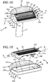
- FIGS 1A-1K depict an adaptor which can be both reversible and not.
- Figures 1D and 1E depict a replacement of the adaptor by a new one.
- Figures 1F and 1G depict an adaptor reversed at least perpendicularly to the axis X-X
- Figures 1H and 1J depict an adaptor reversed at least about the axis X-X
- figure 1K depicts an adaptor reversed both perpendicularly and about the axis X-X.
- one or more bulges 50 can be provided on the frame 34 to allow the attachment and firmly maintain the adaptor 16 onto the shaving cartridge 14 after said snap-fitting occurred.
- the adaptor can be reversible for instance according to its geometry (first opening 36A, second opening 36B, bulge 50, etc.) and to the geometry of the shaving cartridge 14.
- the user can attach a new adaptor 16 by snap-fitting as depicted on Figure 1D , for instance in direction D2 (opposed to direction D1) and shave with a razor as depicted on Figure 1E (provided with a new adaptor).
- the shaving aid 32 was located for instance forward the cutting edges as depicted on Figure 1A and after change of the adaptor, the shaving aid 32 can again be located forward the cutting edges as depicted on Figure 1E
- the adaptor 16 had its first end 42 provided on the left of the shaving cartridge 14 when seen from a top view (or from a top perspective view like Figure 1A ) and its second end 44 is located on the right, whereas after the adaptor 16 is reversed perpendicularly to the axis X-X, its first end 42 provided on the right of the shaving cartridge 14 when seen from a top view (or from a top perspective view like Figure 1G ) and its second end 44 is located on the left.
- the first wall 36 (upper surface of the adaptor 16) is located on the upper face 24C of the shaving cartridge 14
- the second wall 38 lower surface of the adaptor 16
- the first wall 36 (upper surface of the adaptor 16) is still located on the upper face 24C of the shaving cartridge 14
- the second wall 38 (lower surface of the adaptor 16) is still located on the lower face 24D of the shaving cartridge 14 (See Figure 1G ).
- the razor is again ready for shaving.
- the user when the adaptor 16 is reversible about the axis X-X, the user can reverse the frame 34 for instance when the first face 32A of the shaving aid 32 is outworn, such that the second face 32B of the shaving aid 32 can be used during shaving. Actually, the user detaches the frame 34 from the shaving cartridge 14 in unsnapping it from the last (see Figure 1B ), for instance in direction D1.
- the adaptor 16 is completely separated from the shaving cartridge 14 (see Figure 1C )
- the user can either change it by a new one (as disclosed above and in reference to Figure 1D ) or the user can reverse it and attach it onto the shaving cartridge 14 for instance as disclosed below.
- the first opening 36A of the frame which was covering the cutting edges 22 as depicted on Figure 1A is after having reversed the frame 34 on the shaving cartridge 14 covering the lower face 24D of the housing 24 (not depicted), whereas the second opening 38A which covered the lower face 24D of the housing 24 (see Figure 6 ), covers now the shaving blades 20 after having reversed the frame 34 on the shaving cartridge 14 (see Figure 1J or 1K ).
- the first opening 36A of the adaptor 16 which was connected to the shaving cartridge 14 on the upper face 24C is after reversing connected to the lower face 24D of the housing
- the second opening 36B of the adaptor 16 which was connected to the shaving cartridge 14 on the lower face 24D is after reversing about the axis X-X connected to the upper face 24C of the housing.
- the user can bring the adaptor 16 close to the shaving cartridge 14, for instance from the lower side of the housing 24D (see Figure 1H ).
- the user can than snap-fit the adaptor 16 on the shaving cartridge 14 (see Figure 1I ) until complete attachment (see Figure 1J ). After that, the razor is ready again to be used with the shaving aids 32 for further shaving.
- the shaving aid 32 of the razor which is now used for shaving on its second face 32B.
- the location of the shaving aid 32 with regard to the cutting edges 22 is also changed.
- the shaving aid 32 which was for instance located rearward the cutting edges 22 (see Figure 1A ) is now located in front of the blade edges 22 (see Figure 1J ).
- the adaptor 16 before detachment, had its first end 42 provided on the left of the shaving cartridge 14 when seen from a top view (or from a top perspective view like Figure 1A ) and its second end 44 is located on the right, and after the adapter is reversed about the axis X-X, its first end 42 provided is still the left of the shaving cartridge 14 when seen from a top view (or from a top perspective view like Figure 1J ) and its second end 44 is still located on the right.
- the first wall 36 (upper surface of the adaptor 16) is located on the upper face 24C of the shaving cartridge 14
- the second wall 38 lower surface of the adaptor 16
- the first wall 36 (upper surface of the adaptor 16) is now located on the lower face 24D of the shaving cartridge 14
- the second wall 38 (lower surface of the adaptor 16) is now located on the upper face 24C of the shaving cartridge 14 (See Figure 1J or Figure 1K ).
- the razor is again ready for shaving.
- the user has just to further reverse the adaptor perpendicular to the axis X-X.
- the adaptor had its first end 42 provided on the left of the shaving cartridge 14 when seen from a top view (or from a top perspective view like Figure 1A ) and its second end 44 is located on the right, whereas after the adaptor 14 is reversed both perpendicularly to and about the axis X-X, its first end 42 provided on the right of the shaving cartridge 14 when seen from a top view (or from a top perspective view like Figure 1K ) and its second end 44 is located on the left.
- the razor is again ready for shaving.
- the embodiments depicted in the other Figures are provided with two shaving aids 32, but they could be provided with a sole one as above disclosed.
- the reversibility disclosed hereafter is the one which is made about the axis X-X. This reversibility might occur in replacement and/or combination of a reversibility occurring perpendicularly to the axis X-X as disclosed above.
- the adaptor disclosed on Figures 2A-2D can be both reversible and not, whereas figures 2E to 2F depict only a reversible adaptor.
- one or more bulges 50 can be provided on the frame 34 to allow the attachment and firmly maintain the adaptor 16 onto the shaving cartridge 14 after said snap-fitting occurred.
- the adaptor can be reversible for instance according to its geometry (first opening 36A, second opening 36B, bulge 50, etc.) and to the geometry of the shaving cartridge 14.
- the user can attach a new adaptor 16 by snap-fitting as depicted on Figure 2D , for instance in direction D2 (opposed to direction D1) and shave with a razor as depicted on Figure 2A (provided with a new adaptor).
- the user when the adaptor 16 is reversible, the user can reverse the frame 34 when the first faces 32A of the shaving aid 32 are outworn, such that the second faces 32B of the shaving aids 32 can be used during shaving. Actually, the user detaches the frame 34 from the shaving cartridge 14 in unsnapping it from the last (see Figure 2B ), for instance in direction D1.
- the adaptor 16 When the adaptor 16 is completely separated from the shaving cartridge 14 (see Figure 2C ), the user can either change it by a new one (as disclosed above and in reference to Figure 2D ) or the user can reverse it and attach it onto the shaving cartridge 14 for instance as disclosed below.
- the first opening 36A of the frame which was covering the cutting edges 22 as depicted on Figure 2A is after having reversed the frame 34 on the shaving cartridge 14 covering the lower face 24D of the housing 24 (not depicted), whereas the second opening 38A which covered the lower face 24D of the housing 24 (see Figure 6 ), covers now the shaving blades 20 after having reversed the frame 34 on the shaving cartridge 14 (see Figure 2F ).
- the first opening 36A of the adaptor 16 which was connected to the shaving cartridge 14 on the upper face 24C is after reversing connected to the lower face 24D of the housing
- the second opening 36B of the adaptor 16 which was connected to the shaving cartridge 14 on the lower face 24D is after reversing connected to the upper face 24C of the housing.
- the user can bring the adaptor 16 close to the shaving cartridge 14, for instance from the upper side of the housing 24D (see Figure 2E ).
- the user can than snap-fit the adaptor 16 on the shaving cartridge 14 until complete attachment (see Figure 2F ).
- the razor is ready again to be used with the shaving aids 32 for further shaving. More precisely, the shaving aids 32 of the razor which are now used for shaving on their second faces 32B.
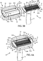
- the adaptor 16 When the adaptor 16 is not reversible, only the first faces 32A of the shaving aids are used during shaving. Thus, when the first faces 32A of the shaving aids 32 are outworn, the user changes the adaptor 16 by a new one. As best depicted on Figure 3B , the user detaches the adaptor 16, more precisely the frame 34, from the shaving cartridge 14 in sliding it from the last especially along arrow F1 and passing the shaving cartridge 14 through a first end opening 42A provided on the first end 42 of the frame 34; more precisely in sliding it along axis X-X.
- the first end opening 42A may be designed as depicted on the drawings to allow the sliding of the adaptor 16 with regard to the shaving cartridge 14 even when the last is connected to the handle body 12; this means that there is no need to detach the shaving cartridge 14 from the handle body 12 when sliding the adaptor 16 from the shaving cartridge 14.
- the adaptor 16 is preferably provided with a second end hole 44A on its second end 44 such that the sliding of the adaptor on the shaving cartridge 14 can be done easily without creating a vacuum effect.
- the user can attach a new adaptor 16 for instance by sliding it along arrow F2 (opposed to arrow F1) in passing the shaving cartridge 14 through the first end opening 42A of the frame 34 (not illustrated); after that the user can shave with a razor as depicted on Figure 3A .
- a new adaptor 16 for instance by sliding it along arrow F2 (opposed to arrow F1) in passing the shaving cartridge 14 through the first end opening 42A of the frame 34 (not illustrated); after that the user can shave with a razor as depicted on Figure 3A .
- one user can also attach the adaptor 16 onto the shaving cartridge 14 in sliding the last with regard to the adaptor 16 along arrow F1 in passing the shaving cartridge 14 through the first end opening 42A of the frame 34; the user can also combine both movements (sliding the adaptor along F2 and sliding the shaving cartridge along F1).
- one or more bulges 50 can be provided on the frame 34 to allow the attachment and firmly maintain of the adaptor 16 onto the shaving cartridge 14 after said sliding occurred in
- the adaptor 14 can be provided with a first end 42 and a second end 44 opposed to the first end 42 which have a U-shape as depicted on Figures 4A to 4H .
- a second end hole as previously mentioned to avoid a vacuum effect since due to their shape in U the first end 42 and the second end 44 are provided with openings 42A and 44A allowing the passage of the shaving cartridge (by sliding).
- the adaptor 16 is slid onto the shaving cartridge 14 either by its second end 44 (not illustrated) when using the first faces 32A of the shaving aid 32 ( Figure 4A ) or by its first end 42 as depicted on Figure 4F for instance, when using the second faces 32B of the shaving aid 32.
- the adaptor 16 When the adaptor 16 is not reversible, only the first faces 32A of the shaving aids are used during shaving. Thus, when the first faces 32A of the shaving aids 32 are outworn, the user changes the adaptor 16 by a new one. As best depicted on Figure 4B , the user detaches the adaptor 16, more precisely the frame 34, from the shaving cartridge 14 in sliding it from the last especially along arrow F1 and passing the shaving cartridge 14 through a first end opening 42A provided on the first end 42 of the frame 34; more precisely in sliding it along axis X-X.
- the first end opening 42A may be designed as depicted on the drawings to allow the sliding of the adaptor 16 with regard to the shaving cartridge 14 even when the last is connected to the handle body 12; this means that there is no need to detach the shaving cartridge 14 from the handle body 12 when sliding the adaptor 16 from the shaving cartridge 14.
- the user can attach a new adaptor 16 for instance by sliding along arrow F2 (opposed to arrow F1) in passing the shaving cartridge 14 through the first end opening 42A of the frame 34; after that the user can shave with a razor as depicted on Figure 4A .
- arrow F2 opposite to arrow F1
- the user can also attach the adaptor 16 onto the shaving cartridge 14 in sliding the last with regard to the adaptor 16 along arrow F1 in passing the shaving cartridge 14 through the first end opening 42A of the frame 34; the user can also combine both movements (sliding the adaptor along F2 and sliding the shaving cartridge along F1).
- one or more bulges 50 can be provided on the frame 34 to allow the attachment and firmly maintain of the adaptor 16 onto the shaving cartridge 14 after said sliding occurred in order to shave.
- the user can reverse the frame 34 when the first faces 32A of the shaving aid 32 are outworn, such that the second faces 32B of the shaving aids 32 can be used during shaving.
- the user detaches the frame 34 from the shaving cartridge 14 in sliding it from the last (see Figure 4B ) along arrow F1 in passing the shaving cartridge 14 through the first end opening 42A of the frame 34; more precisely in sliding the frame 34 along axis X-X.
- the adaptor is completely separated from the shaving cartridge 14 (see Figure 4B )
- the user can reverse it in rotating/twisting it around axis X-X for instance (see Figures 4C to 4E ).
- the first opening 36A of the frame which was covering the cutting edges 22 as depicted on Figure 4A is after having reversed the frame 34 on the shaving cartridge 14 covering the lower part of the housing 24D (see Figure 4H ), whereas the second opening 38A which covered the upper face of the housing 24C (see Figure 7 ), covers the shaving blades 20 after having reversed the frame 34 on the shaving cartridge 14 (see Figure 4G ).
- the first opening 36A of the adaptor 16 which was connected to the shaving cartridge 14 on the upper face 24C is after reversing connected to the lower face 24D of the housing
- the second opening 36B of the adaptor 16 which was connected to the shaving cartridge 14 on the lower face 24D is after reversing connected to the upper face 24C of the housing.
- the user can than slide the adaptor 16 on the shaving cartridge 14 (see Figure 4F ) until complete attachment (see Figure 4G ). After that, the razor is ready again to be used with the shaving aids 32 for further shaving.
- the adaptor 16 When the adaptor 16 is not reversible this means that only the first faces 32A of the shaving aids can be used during shaving. Thus, when the first faces 32A of the shaving aids 32 are outworn, the user changes the adaptor 16 by a new one.
- the adaptor is reversible, as depicted on Figures 5A and 5B , when each of the shaving aids 32 is provided with a first face 32A and a second face 32B, each of them being able to contact the skin during shaving.
- the frame 34 of the adaptor 14 comprises for instance two parts 34A and 34B linked pivotally together by a hinge 35. Opposed to that hinge 35, several tabs 33 can be provided on the frame 34 to secure the closure of the adaptor 14 as illustrated on Figure 5A .
- the adaptor 16 When the adaptor 16 is not reversible, only the first faces 32A of the shaving aids are used during shaving. Thus, when the first faces 32A of the shaving aids 32 are outworn, the user changes the adaptor 16 by a new one. As best depicted on Figure 5B , the user opens the adaptor 16 in pivoting one part of the frame with regard to the other one about the hinge 35. The user can than attach a new adaptor 16 by encasing the shaving cartridge in it and shave with a razor 10 as depicted on Figure 5A .
- the user can reverse the frame 34 when the first faces 32A of the shaving aid 32 are outworn, such that the second faces 32B of the shaving aids 32 can be used during shaving.
- the user detaches the frame 34 from the shaving cartridge 14 in opening the hinge 34 (see Figure 5B ) and when the adaptor is completely separated from the shaving cartridge 14 (see Figure 5B ), the user can reverse it in twisting it around axis X-X for instance.
- the first opening 36A of the frame which was covering the cutting edges 22 as depicted on Figure 5A is after having reversed the frame 34 on the shaving cartridge 14 covering the lower part of the housing 24D (not illustrated), whereas the second opening 38A which covered the lower face of the housing, covers the shaving blades 20 after having reversed the frame 34 on the shaving cartridge 14 (s not illustrated).
- the first opening 36A of the adaptor 16 which was connected to the shaving cartridge 14 on the upper face 24C is after reversing connected to the lower face 24D of the housing
- the second opening 36B of the adaptor 16 which was connected to the shaving cartridge 14 on the lower face 24D is after reversing connected to the upper face 24C of the housing.
- Each of the above disclosed adaptors can be provided with shaving aid holders 46 which are unitary with the frame 34 or which are removably attached to the frame such disconnected from the frame 34 of the adaptor 16 as depicted for instance on Figure 8 .
- the frame 16 can be maintained on the shaving cartridge 14 and the user can either remove the shaving aid holders 46 in order to change it by a new one or the user can reverse the shaving aid holders 46.
- the shaving aid provided on the frame has two opposed faces each of which can successively be used during shaving in reversing the faces.
- This reverse of the two opposed faces 32A and 32B of one shaving aid 32 may be obtained in reversing the complete adaptor 16 (more precisely the frame 34) with regard to the shaving cartridge 14 and/or in reversing the holder 46 of the shaving aid 32 with regard to the frame 34.
- the reversibility of the adaptor (the frame and/or each shaving aid) is obtained especially by twisting or reversal.
- the shaving aid 32 is preferably motionless with regard to the frame 34; this means that the holder 46 of the shaving aid 32 cannot move with regard to the frame 34 especially during shaving.
- the invention is not limited to this kind of embodiments and the shaving aid 32 can be movable with regard to the frame 34, for instance the holder 46 of the shaving aid 32 can flex and/or translate with regard to the frame 34.
- the adaptor comprises preferably a material chosen among the plastic, like for instance thermoplastic like PP, PS and/or ABS.
- the adaptor of the invention can be provided with one or more bulges 50 on the frame 34 to allow the attachment and firmly maintain of the adaptor 16 onto the shaving cartridge 14 after said sliding occurred in order to shave securely (avoiding any risk of untimely detachment of the adaptor). Any other means can be provided to retain securely the adaptor on the shaving cartridge in order to avoid any risk of untimely detachment of the adaptor when shaving.
- the reversibility of the adaptor of the invention is obtained in pivoting/twisting/revolving the adaptor with regard to the shaving cartridge as disclosed above.
Landscapes
- Life Sciences & Earth Sciences (AREA)
- Forests & Forestry (AREA)
- Engineering & Computer Science (AREA)
- Mechanical Engineering (AREA)
- Cosmetics (AREA)
- Dry Shavers And Clippers (AREA)
- Packaging Of Annular Or Rod-Shaped Articles, Wearing Apparel, Cassettes, Or The Like (AREA)
- Cleaning And Drying Hair (AREA)
Abstract
Description
- The invention relates to adaptors for shaving cartridges, to shaving assemblies including a cartridge and an adaptor, to a razor having a razor handle and such an assembly and to methods of shaving.
- In particular, the invention is related to shaving cartridges and shaving razors having a shaving aid directly attached on the shaving cartridge.
- Such razors avoid the use of shaving preparation like shaving foam, gel or cream to be put on the skin before shaving. Besides, such shaving aid provided directly on the shaving cartridge allows shaving within a wet shaving environment, for instance, within a shower where a shaving preparation will be immediately removed by the water before the surface can be shaved.
- Therefore, shaving cartridges have been provided with additional shaving aids attached on the shaving cartridge in order to improve the shaving.
- However, the shaving cartridges provided with additional shaving aids are connected permanently to the shaving aids. As a result, when the shaving aid is outworn while the shaving blades are not dulled the entire shaving cartridge (with the additional shaving aid) needs to be thrown unless the shaving is to be achieved degraded.
- Therefore, the known shaving cartridges do not allow shaving in good conditions as soon as the shaving aid is outworn unless changing the entire shaving cartridge. In addition, the user is given the option to remove one or more of the shaving aids, for instance when precision is needed or for hygiene reasons.
- To this aim, it is provided an adaptor for a shaving cartridge, wherein the adaptor is provided with at least one shaving aid, and wherein the adaptor is slidably mountable on a shaving cartridge having one or more shaving blades, each of shaving blades being provided with a cutting edge.
- To this aim, it is provided an adaptor for a shaving cartridge, wherein the adaptor is provided with at least one shaving aid, and wherein the adaptor is reversibly mountable on a shaving cartridge having one or more shaving blades, each of shaving blades being provided with a cutting edge.
- To this aim, it is provided an adaptor for a shaving cartridge, wherein the adaptor comprises a frame which is provided with at least one shaving aid, wherein the adaptor is mountable on a shaving cartridge having one or more shaving blades, each of shaving blades being provided with a cutting edge and wherein the at least one shaving aid is reversibly mounted on the frame.
- The reversibility of the adaptor of the invention can be with regard to a plane, (the shaving aid is reversed by rotation about an axis perpendicular to that plane), whereas it can also mean with regard to an axis contained in that plane (the shaving aid is reversed by rotation about an axis contained in that plane).
- When the reversibility is made in a plane (for instance, the plane containing the cutting edges), the at least one shaving aid location will change with regard to the position of the cutting edge. More precisely, when the shaving aid is located forwardly in front of the cutting edges, after being reversed it will be located rearwardly the cutting edges. This means that the same surface of the shaving aid is used for shaving; it is just its location with regard to the blades that changes.
- When the reversibility is made perpendicular to a plane (for instance, the plane containing the cutting edges), the at least one shaving aid location will not change with regard to the position of the cutting edge. More precisely, when the shaving aid is located forwardly in front of the cutting edges, after being reversed it will still be located forwardly the cutting edges. This means that an opposite surface of the shaving aid is used for shaving; the shaving aid has in that case preferably a first face and an opposed second face.
- The adaptor of the present invention thus allows a further use of a shaving cartridge when the shaving aid is outworn.
- In various embodiments of the invention, one and/or the other of the following features may be incorporated in this adaptor alone or in mutual combination:
- the adaptor is adapted to be slidably mountable and/or mountable by snap-fit or by encasing on a shaving cartridge having one or more shaving blades, each of shaving blades being provided with a cutting edge.
- further comprising a frame, the frame having a first wall, a second wall opposed to said first wall, a side wall extending from said first wall to said second wall, a first end and an opposed second end, the first wall having a first opening, wherein the frame is mountable on a shaving cartridge such that the cutting edge of the one or more shaving blades is uncovered and is accessible through the first opening for shaving; in that case, the second wall of the frame may have a second opening and the frame might be mountable on a shaving cartridge such that the cutting edge of the one or more shaving blades is uncovered and is accessible through either the first opening or the second opening; besides, the frame might comprise two parts connected by a hinge; besides, the first end might have a first end opening and the frame is able to be slidably mountable on a shaving cartridge through the first end opening.
- the adaptor is adapted to frictionally receive the shaving cartridge.
- the adaptor is releasably mountable on the shaving cartridge.
- the adaptor is elastically mountable on the shaving cartridge.
- the at least one shaving aid has a shaving aid body comprising a lubricant, a moisturizer, a conditioner and/or an exfoliant.
- the adaptor further comprises at least one shaving aid holder configured to hold the at least one shaving aid, and especially the shaving aid body.
- further comprising a frame, wherein the at least one shaving aid is releasable with regard to the frame.
- further comprising a frame, wherein the at least one shaving aid is motionless with regard to the frame.
- The invention also concerns a shaving assembly comprising a shaving cartridge having one or more shaving blades, each of shaving blades being provided with a cutting edge and an adaptor, wherein the adaptor is mountable on the shaving cartridge and wherein the at least one shaving aid extends outwardly with regard to the shaving cartridge when the adaptor is mounted on the shaving cartridge.
- The invention also concerns a razor comprising a razor handle and such a shaving assembly, wherein the shaving assembly is provided with connecting means for connecting the shaving assembly to the razor handle.
- The invention also concerns a method of shaving with such a razor according, wherein the shaving aid is changed and/or is reversed on the shaving cartridge when outworn while the razor handle and the shaving head are kept.
- Other characteristics and advantages of the invention will readily appear from the following description of one embodiment, provided as non-limitative examples, in reference to the accompanying drawings.
- In the drawings:
-
Figure 1A is a perspective view of an adaptor according to the invention connected to a shaving cartridge itself connected to a handle body. -
Figure 1B is a perspective view of the razor ofFigure 1A , illustrating the method of detaching the adaptor ofFigure 1A from the shaving cartridge. -
Figure 1C is a sectional view of the razor ofFigure 1A , illustrating the method of detaching the adaptor ofFigure 1A from the shaving cartridge. -
Figures 1D-1E are perspective views of the razor ofFigure 1A , illustrating a method of attaching the adaptor ofFigure 1A on the shaving cartridge. -
Figures 1F-1G are perspective views of the razor ofFigure 1A , illustrating another method of attaching the adaptor ofFigure 1A on the shaving cartridge. -
Figures 1H-1J are perspective views of the razor ofFigure 1A , illustrating another method of attaching the adaptor ofFigure 1A on the shaving cartridge. -
Figure 1K is a perspective view of a razor ofFigure 1A , the adaptor having being reversed on the shaving cartridge according to another method of attaching the adaptor ofFigure 1A on the shaving cartridge. -
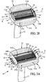
Figure 2A is a perspective view of an adaptor according to the invention connected to a shaving cartridge itself connected to a handle body. -
Figures 2B and2D are perspective views of the razor ofFigure 2A , illustrating the method of attaching/detaching the adaptor ofFigure 2A from the shaving cartridge. -
Figures 2C and2E are sectional views of the razor ofFigure 2A , illustrating the method of attaching/detaching the adaptor ofFigure 2A from the shaving cartridge. -
Figure 2F is a perspective view of a razor ofFigure 2A , the adaptor having being reversed on the shaving cartridge with regard to the attachment illustrated onFigure 2A . -
Figure 3A is a perspective view of an adaptor according to another embodiment connected to a shaving cartridge itself connected to a handle body. -
Figures 3B is a perspective view of the razor ofFigure 3A , illustrating the method of attaching/detaching the adaptor ofFigure 3A from the shaving cartridge. -
Figure 4A is a perspective view of an adaptor according to another embodiment connected to a shaving cartridge itself connected to a handle body. -
Figures 4B-4F are perspective views of the razor ofFigure 4A , illustrating the method of attaching/detaching the adaptor ofFigure 4A from the shaving cartridge. -
Figure 4G is a perspective view of a razor ofFigure 4A , the adaptor having being reversed on the shaving cartridge with regard to the attachment illustrated onFigure 4A . -
Figure 4H is a perspective view of a razor ofFigure 4G viewed from the lower side of the shaving cartridge. -
Figure 5A is a perspective view of an adaptor according to another embodiment connected to a shaving cartridge itself connected to a handle body. -
Figure 5B is perspective view of the adaptor ofFigure 5A without the shaving cartridge and opened. -
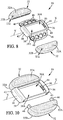
Figure 6 is a perspective view of the shaving assembly ofFigure 1A or2A viewed from the lower side of the shaving cartridge. -
Figure 7 is a perspective view of the shaving assembly ofFigure 4A viewed from the lower side of the shaving cartridge. -
Figure 8 is an exploded perspective view of the adaptor of the invention. -
Figures 9A-9C are upper views of a shaving assembly with an adaptor according to another embodiment, illustrating the method of reversing the shaving aid, from the shaving cartridge. -
Figure 10 is an exploded perspective view of the adaptor of the invention having detachable shaving aids. - On the different Figures, the same reference signs designate identical or similar elements.
-
Figures 1A ,2A ,3A ,4A ,5A and9A illustrate awet razor 10 according to the invention, comprising arazor handle 12, a shavingcartridge 14 and anadaptor 16 which can be connected to the shavingcartridge 14 as illustrated on the Figures such to form a shavingassembly 18. - More precisely,
Figures 1A-1K and2A-2F illustrate an adaptor connected to the shavingcartridge 14 by snap-fit on oneshaving cartridge 14,Figures 3A-3B and4A-4H illustrates an adaptor slidably mounted on oneshaving cartridge 14,Figures 5A-5B illustrates an adaptor mounted by encasing on oneshaving cartridge 14 andFigures 9A-9C illustrates an adaptor having shaving aids reversibly mounted on the frame the adaptor. - The adaptors disclosed in the Figures can either be reversible or not as further disclosed hereafter.
- As depicted on the Figures, the shaving
cartridge 14 has one ormore shaving blades 20, each of theshaving blades 20 being provided with acutting edge 22. More precisely, the shavingcartridge 14 comprises ahousing 24 which has afront edge 24A and arear edge 24B, anupper face 24C and an opposedlower face 24D and into which the one ormore shaving blades 20 are located (between the front edge and the rear edge). Theshaving blades 20 might be movably mounted on elastic fingers provided on the housing or might be fixed. The number ofshaving blades 20 might be comprised between one and five for instance, and is preferably of three or four. - The
housing 24 is preferably elongated, extending along a longitudinal axis X-X. Aguard bar 26 and respectively alubra 28 might be also provided on theupper face 24C of thehousing 24, respectively in front theshaving blades 20 and aft them. - The
cutting edge 22 of eachshaving blades 20 extends preferably longitudinally along the longitudinal axis X-X. - The shaving assembly is provided with connecting means for connecting the shaving
assembly 18 to the razor handle 12. More precisely, either the shavingcartridge 14 or theadaptor 16 can be provided with connecting means for connecting the shavingassembly 18 to the razor handle 12. According to the connecting means, the connection between the razor handle 12 and the shavingassembly 18 is fixed or pivotable. - In the examples depicted on the figures, the connecting means 30 (as best seen on
Figures 4H ,6 and 7 ) allow a pivot of the shavingassembly 18 with regard to the razor handle 12 (around the elongated axis X-X), but the invention is not limited to a pivotable shaving assembly. As illustrated, the connectingmeans 30 are preferably provided on the shaving cartridge 14 (on thelower face 24D of the housing 24), especially when theadaptor 16 is reversible as described in details below. - The reversibility disclosed in the present invention concerns two kinds:
- a reversibility about the longitudinal axis X-X.
- a reversibility sensibly perpendicular to the longitudinal axis X-X.
- The connecting means 30 can comprise shell bearings, especially when the shaving
assembly 18 is pivotable with regard to the razor handle 12, but the invention is not limited to this kind of connecting means. Besides, thehandle 12 can be detachable from the shavingcartridge 14 or non-detachable according to the razor; more precisely, thehandle 12 is detachable when the razor is a system (meaning the shavingcartridge 14 is changed by a new one when the blades are dulled, while the handle is kept), whereas the handle is non-detachable when the razor is a disposable one (meaning both the shavingcartridge 14 and the handle are changed by new ones when the blades are dulled). - The
adaptor 16 of the invention is provided with at least one shaving aid and is preferably provided with two shaving aids or four shaving aids (not illustrated). In the examples depicted on the figures, theadaptor 16 is provided with one or two shaving aids 32 (one of them being located in front of the forward-most blade and the other one being located aft of the aft-most blade, when theadaptor 16 is mounted on the shaving cartridge 14). The shaving aids 32 extend longitudinally along the longitudinal axis X-X. Besides, at least one or two other shaving aid(s) can further be provided on the adaptor (not depicted), more precisely on its lateral faces, obliquely with regards to the cutting edges. - As best seen on
Figures 1A ,2A ,3A ,4A and5A theadaptor 16 comprises preferably aframe 34 having a first wall 36 (upper surface), a second wall 38 (lower surface) opposed to saidfirst wall 36, aside wall 40 extending from saidfirst wall 36 to saidsecond wall 38, afirst end 42 and asecond end 44 opposed to thefirst end 42. - The
first wall 36 has afirst opening 36A and thesecond wall 38 of the frame has asecond opening 38A as best visible onFigures 1C ,2C ,3B ,4B-4F ,5B ,6 and 7 . In reference toFigures 1A ,2A ,3A ,4A and5A when theframe 34 is mounted on the shavingcartridge 14, thecutting edge 22 of theshaving blades 20 is at least partly, preferably totally (Figure 2A ,4A and5A ), uncovered by the adaptor and is accessible through thefirst opening 36A in order to allow the shaving, whereas thesecond opening 38A allows the connecting means 30 to be accessible and to be connected to a razor handle. - When the adaptor is reversible around axis X-X, the
second opening 38A is also designed, as detailed after, such that the cutting edge of the one or more shaving blades is at least partially uncovered and is accessible through thesecond opening 38A when the adaptor is reversed on the shaving cartridge 14 (by rotation about axis X-X). - In reference to
Figures 1A-1C and1H-1K , toFigures 2A-2F ,4A-4G and toFigures 5A-5B , when theadaptor 16 is reversibly mountable on the shavingcartridge 14, theframe 34 might be reversely mountable on the shavingcartridge 14; in that last case, thecutting edge 22 of theshaving blades 20 is at least partly, preferably totally, uncovered by theadaptor 16 and is accessible through thesecond opening 38A in order to allow the shaving, whereas thefirst opening 36A allows the connecting means 30 to be accessible and to be connected to a razor handle. Thus, in that case, theframe 34 of theadaptor 16 can be mounted on the shavingcartridge 14 such that the cutting edges 22 are accessible through either thefirst opening 36A or thesecond opening 38A. For the embodiments depicted onFigures 1A-1C and1H-1K and onFigures 2A-2F (snap-fitting), according to the shape and dimension of thefirst opening 36A and of thesecond opening 38A, the connection to the shavingcartridge 14 might be obtained from thefirst opening 36A and/or from thesecond opening 38A (Figures 1H and2E ) . - The
adaptor 16 can further comprise at least one shaving aid holder configured to hold the at least one shaving aid. More precisely, as best seen onFigure 8 , which illustrates only the adaptor (without the shaving cartridge and the handle), theadaptor 16 comprises two shavingaid holders 46, each provided with one shavingaid 32. - When the adaptor has only one
shaving aid 32 and it is attached to a shaving cartridge (seefigure 1A ), only oneshaving aid holder 46 is provided and it extends outwardly with regard to the shavingcartridge 14 when theadaptor 16 is mounted on the shavingcartridge 14. The shavingaid holders 46 can be located in front of the forward-most blade (and in front of theguard bar 26 when it exists) or as depicted onFigure 1A it can be located aft of the aft-most blade (and aft of thelubra 28 when it exists). - When attached to one shaving cartridge (see
figures 2A ,3A ,4A and5A ), one of the shavingaid holders 46 extends outwardly with regard to the shavingcartridge 14 when theadaptor 16 is mounted on the shavingcartridge 14, and is located in front of the forward-most blade (and in front of theguard bar 26 when it exists) and the other one is located aft of the aft-most blade (and aft of thelubra 28 when it exists). - Each of the shaving aids 32 has a
shaving aid body 32 which is preferably solid and which can comprise a lubricant, a moisturizer, a conditioner and/or an exfoliant. - The shaving aids 32 can be designed such that they are provided with two opposed faces. More precisely, each shaving
aid 32 has afirst face 32A and an opposedsecond face 32B. The shape of the shaving aids can be of several kinds; for instance, the shapes of the first andsecond faces face aid 32 is adapted to the height of the adaptor and to the height of the shavingcartridge 14 such that when the adaptor is mounted on the shavingcartridge 14, thecorresponding face 32A (or 32B) enters in contact with the skin of the user during shaving (and at least one of the cutting edges is also in contact with the skin of the user during shaving). - The shaving aid holder is configured to hold the shaving aids 32 such that during shaving only one of the
faces aid 32. This means, that as depicted onFigure 1A , when thefirst face 32A of the shavingaid 32 is able to be used during shaving, the opposed faces 32B is not accessible to be used for shaving. This means, that as depicted onFigures 2A ,3A ,4A and5A , when the adaptor is provided with two shaving aids the twofirst faces 32A of the shaving aids 32 are able to be used during shaving, whereas the twoopposed faces 32B are not accessible to be used for shaving. - When the
adaptor 16 is reversible about axis X-X, both faces of each shaving aids 32 can be successively used. Actually, thefirst face 32A of each shavingaid 32 is useful when the cutting edges 22 are accessible through thefirst opening 36A, whereas thesecond face 32B of each shaving aids 32 is useful when the cutting edges 22 are accessible through thesecond opening 38A (after having reversed the adaptor on the shaving cartridge). Thus, when thefirst face 32A of the shaving aids 32 is outworn, theadaptor 16 can be reversed by the user such that thesecond face 32B of each shaving aids 32 can be used during further shaving (as depicted onFigures 1G ,2F and4G ). - As already mentioned, the adaptor of the invention can be mounted on the shaving cartridge, slidably, by snap-fit and/or by encasing. Besides, the adaptor of the invention can be reversible or not. To be changed (either by reversing or by a new adaptor), the adaptor is preferably detachable from the shaving cartridge. Besides, the adaptor of the invention can be reversible around the longitudinal axis X-X and/or transversally to it.
- The
adaptor 16 receives preferably frictionally the shavingcartridge 14 such that it can be mounted and naturally maintained on the shavingcartridge 14; this means that theframe 34 of theadaptor 16 is designed to cooperate with friction with thehousing 24 of the shavingcartridge 14. - The adaptor can also be elastically mountable on the shaving cartridge; more precisely, the
frame 34 of the adaptor might deform elastically during its connection to the shavingcartridge 14. This means that the elasticity of theframe 34 is higher than that of the shavinghousing 24. - According to the friction forces and to the elasticity of the adaptor, after mounting, the
adaptor 16 can be definitely connected to the shavingcartridge 14 or preferably releasably (i.e. detachably) connected to the shavingcartridge 14. When theadaptor 16 is releasably connected to the shavingcartridge 14, the friction between theadaptor 16 and the shavingcartridge 14 might be such that theadaptor 16 is maintained on the shavingcartridge 14 such that it allows the shaving without any risk of detachment. Besides, the voluntary release/detachment of theadaptor 16 from the shavingcartridge 14 can be realized without using of a significant force (a child may obtain the separation of the adaptor from the shaving cartridge) and without help of any tool. - When the
adaptor 16 is releasably connected (detachable) to the shavingcartridge 14, the user can shave with or without the adaptor. Besides, when the shaving aids 32 are outworn, the user can change the adaptor by a new one, while keeping thesame shaving cartridge 14 and the same razor handle 12. - In summary, in relation with the different kinds of connections between the adaptor and the cartridge as described just above (snap-fitting, sliding, encasing), the
adaptor 16 of the invention can be reversibly mounted on the shavingcartridge 14. - The reversibility of the
adaptor 16 can be obtained either with areversible frame 34 as described above (in reference toFigures 1A-11C and1F-1K , toFigures 2A-2F ,4A-4H and toFigures 5A-5B ) and/or with reversible shaving aids 32 as described hereafter and in reference toFigures 9A-9C and 10. When the shaving aids 32 are outworn, the user can thus either reverse theframe 34 of theadaptor 16 on the shavingcartridge 14 or reverse the shaving aid on the shaving cartridge, more precisely on the frame onto which they are reversibly attached. Besides, the shaving aid can be releasable with regard to the frame such that it can be changed by another one when outworn or kept in being reversed on the frame to allow its second face to be used. - When the shaving aids 32 are unreleasably (inseparably or non-detachable) maintained on the shaving
aid holders 46, they are preferably molded on the last. As best seen onfigure 8 , the shavingaid holders 46 are in that case preferably provided withholes 48 through which the shaving aids 32 can spread through during manufacturing. After manufacturing, the shaving aids 32 are non detachable from the shavingaid holders 46, like anchored on the shavingaid holders 46. - The shaving
aid holders 46 can be unitary with theframe 34 of theadaptor 16 and extend from theside wall 40 such that the shavingaid holders 46 are unreleasably (inseparably) connected on theframe 34 as depicted onFigure 6 . - When the shaving
aid 32 is outworn, the user needs to change thewhole adaptor 14 by a new one unless it is reversible. - In reference to
Figures 9A-9C , the shaving aids 32 are attached to the shavingaid holders 46, preferably unreleasably, whereas each of the shavingaid holders 46 is reversibly mounted on theframe 34, for instance in being rotatably mounted on theframe 34. As depicted on thefigures 9A-9C , the shavingaid holders 46 are able to be twisted on theframe 34 such that when outworn thefirst face 32A can be replaced by the opposedsecond face 32B for further shaving without detaching theadaptor 16 from the shavingcartridge 14. More precisely,Figure 9A illustrates the adaptor with both first faces 32A to be used during shaving,Figure 9B illustrates the way of reversing the face (from first to second) for instance by twisting it andFigure 9C illustrated the adaptor with onesecond face 32B to be used during shaving (theother shaving aid 32 one be still used with itsfirst face 32A). Theadaptor 16 can thus be used during shaving either with bothfirst faces 32A, with both second faces 32B or with a mix of afirst face 32A and asecond face 32B. The shavingaid holders 46 might besides also are a little bit slidably mounted on theframe 34 to avoid any friction of the shaving aids 32 when reversed on theframe 34. - In reference to
Figure 10 , the shaving aids 32 are attached to the shavingaid holders 46, whereas each of the shavingaid holders 46 is releasably mounted on theframe 34. The shavingaid holders 46 are able to be attached on and detached from theframe 34 such that when outworn thefirst face 32A can be replaced by the opposedsecond face 32B for further shaving without detaching theadaptor 16 from the shavingcartridge 14. Theframe 34 may allow an attachment to the shaving cartridge by sliding, snap-fitting (as illustrated onFigure 10 ) or by encasing. - We will now describe the method of using an adaptor attached on the shaving cartridge by snap-fitting (see
Figures 1A-1K ).Figures 1A to 1C depict an adaptor which can be both reversible and not.Figures 1D and1E depict a replacement of the adaptor by a new one.Figures 1F and1G depict an adaptor reversed at least perpendicularly to the axis X-X,Figures 1H and1J depict an adaptor reversed at least about the axis X-X, andfigure 1K depicts an adaptor reversed both perpendicularly and about the axis X-X. - As best seen on
Figures 1B to 1D ,1F and1H , one ormore bulges 50 can be provided on theframe 34 to allow the attachment and firmly maintain theadaptor 16 onto the shavingcartridge 14 after said snap-fitting occurred. Actually, the adaptor can be reversible for instance according to its geometry (first opening 36A,second opening 36B,bulge 50, etc.) and to the geometry of the shavingcartridge 14. - In reference to
Figures 1A-1E , when theadaptor 16 is not reversible, only the first faces 32A of the shaving aids are used during shaving. Thus, when the first faces 32A of the shaving aids 32 are outworn, the user changes theadaptor 16 by a new one. As best depicted onFigure 1B , the user detaches theadaptor 16, more precisely theframe 34, from the shavingcartridge 14 in unsnapping it from the last, for instance in direction D1. When the adaptor is completely separated from the shavingcartridge 14 as depicted onFigure 1C , the user can attach anew adaptor 16 by snap-fitting as depicted onFigure 1D , for instance in direction D2 (opposed to direction D1) and shave with a razor as depicted onFigure 1E (provided with a new adaptor). The shavingaid 32 was located for instance forward the cutting edges as depicted onFigure 1A and after change of the adaptor, the shavingaid 32 can again be located forward the cutting edges as depicted onFigure 1E - In reference to
Figures 1A-1C and further toFigures 1F-1G or toFigure 1K , when theadaptor 16 is reversible perpendicularly to the axis X-X, the user can reverse theframe 34 such that the user changes the location of the shavingaid 32 with regard to the cutting edges 22. Actually, the user detaches theframe 34 from the shavingcartridge 14 in unsnapping it from the last (seeFigure 1B ), for instance in direction D1. When theadaptor 16 is completely separated from the shaving cartridge 14 (seeFigure 1C ), the user can rotate it in order to change its location on the shaving cartridge 14 (seeFigure 1F ) and snap-fit it in order to connect it the shaving cartridge 14 (seeFigure 1G ). As depicted onFigure 1A before detachment, theadaptor 16 had itsfirst end 42 provided on the left of the shavingcartridge 14 when seen from a top view (or from a top perspective view likeFigure 1A ) and itssecond end 44 is located on the right, whereas after theadaptor 16 is reversed perpendicularly to the axis X-X, itsfirst end 42 provided on the right of the shavingcartridge 14 when seen from a top view (or from a top perspective view likeFigure 1G ) and itssecond end 44 is located on the left. Besides, since the reversibility disclosed here concerns the one occurring perpendicularly to the axis X-X, before detachment, the first wall 36 (upper surface of the adaptor 16) is located on theupper face 24C of the shavingcartridge 14, the second wall 38 (lower surface of the adaptor 16) is located on thelower face 24D of the shaving cartridge 14 (seeFigure 1A ), and after theadaptor 16 is reversed perpendicularly to the axis X-X the first wall 36 (upper surface of the adaptor 16) is still located on theupper face 24C of the shavingcartridge 14, the second wall 38 (lower surface of the adaptor 16) is still located on thelower face 24D of the shaving cartridge 14 (SeeFigure 1G ). The razor is again ready for shaving. - In reference to
Figures 1A-1C and further toFigures 1H-1J or toFigure 1K , when theadaptor 16 is reversible about the axis X-X, the user can reverse theframe 34 for instance when thefirst face 32A of the shavingaid 32 is outworn, such that thesecond face 32B of the shavingaid 32 can be used during shaving. Actually, the user detaches theframe 34 from the shavingcartridge 14 in unsnapping it from the last (seeFigure 1B ), for instance in direction D1. When theadaptor 16 is completely separated from the shaving cartridge 14 (seeFigure 1C ), the user can either change it by a new one (as disclosed above and in reference toFigure 1D ) or the user can reverse it and attach it onto the shavingcartridge 14 for instance as disclosed below. - The
first opening 36A of the frame which was covering the cutting edges 22 as depicted onFigure 1A is after having reversed theframe 34 on the shavingcartridge 14 covering thelower face 24D of the housing 24 (not depicted), whereas thesecond opening 38A which covered thelower face 24D of the housing 24 (seeFigure 6 ), covers now theshaving blades 20 after having reversed theframe 34 on the shaving cartridge 14 (seeFigure 1J or1K ). Thefirst opening 36A of theadaptor 16 which was connected to the shavingcartridge 14 on theupper face 24C is after reversing connected to thelower face 24D of the housing, whereas thesecond opening 36B of theadaptor 16 which was connected to the shavingcartridge 14 on thelower face 24D is after reversing about the axis X-X connected to theupper face 24C of the housing. Than, the user can bring theadaptor 16 close to the shavingcartridge 14, for instance from the lower side of thehousing 24D (seeFigure 1H ). The user can than snap-fit theadaptor 16 on the shaving cartridge 14 (seeFigure 1I ) until complete attachment (seeFigure 1J ). After that, the razor is ready again to be used with the shaving aids 32 for further shaving. More precisely, the shavingaid 32 of the razor which is now used for shaving on itssecond face 32B. The location of the shavingaid 32 with regard to the cutting edges 22 is also changed. The shavingaid 32 which was for instance located rearward the cutting edges 22 (seeFigure 1A ) is now located in front of the blade edges 22 (seeFigure 1J ). In other words, before detachment, theadaptor 16 had itsfirst end 42 provided on the left of the shavingcartridge 14 when seen from a top view (or from a top perspective view likeFigure 1A ) and itssecond end 44 is located on the right, and after the adapter is reversed about the axis X-X, itsfirst end 42 provided is still the left of the shavingcartridge 14 when seen from a top view (or from a top perspective view likeFigure 1J ) and itssecond end 44 is still located on the right. Besides, since the reversibility disclosed here concerns the one occurring about the axis X-X, before detachment, the first wall 36 (upper surface of the adaptor 16) is located on theupper face 24C of the shavingcartridge 14, the second wall 38 (lower surface of the adaptor 16) is located on thelower face 24D of the shaving cartridge 14 (seeFigure 1A ), and after theadaptor 16 is reversed perpendicularly to the axis X-X the first wall 36 (upper surface of the adaptor 16) is now located on thelower face 24D of the shavingcartridge 14, the second wall 38 (lower surface of the adaptor 16) is now located on theupper face 24C of the shaving cartridge 14 (SeeFigure 1J orFigure 1K ). The razor is again ready for shaving. - When the user want also to change the location of the shaving aid (with regard to the cutting edges 22), the user has just to further reverse the adaptor perpendicular to the axis X-X. In that case, the adaptor had its
first end 42 provided on the left of the shavingcartridge 14 when seen from a top view (or from a top perspective view likeFigure 1A ) and itssecond end 44 is located on the right, whereas after theadaptor 14 is reversed both perpendicularly to and about the axis X-X, itsfirst end 42 provided on the right of the shavingcartridge 14 when seen from a top view (or from a top perspective view likeFigure 1K ) and itssecond end 44 is located on the left. The razor is again ready for shaving. - Apart from this embodiment depicted in
Figures 1A-1K , the embodiments depicted in the other Figures are provided with two shaving aids 32, but they could be provided with a sole one as above disclosed. Besides, the reversibility disclosed hereafter is the one which is made about the axis X-X. This reversibility might occur in replacement and/or combination of a reversibility occurring perpendicularly to the axis X-X as disclosed above. - We will now describe the method of using an adaptor of the embodiment depicted in
Figures 2A-2F and which is also attached on the shaving cartridge by snap-fitting. - Like the adaptor disclosed on
Figures 1A-1K , the adaptor disclosed onFigures 2A-2D can be both reversible and not, whereasfigures 2E to 2F depict only a reversible adaptor. As best seen onFigures 2B to 2E , one ormore bulges 50 can be provided on theframe 34 to allow the attachment and firmly maintain theadaptor 16 onto the shavingcartridge 14 after said snap-fitting occurred. Actually, the adaptor can be reversible for instance according to its geometry (first opening 36A,second opening 36B,bulge 50, etc.) and to the geometry of the shavingcartridge 14. - In reference to
Figures 2A-2D , when theadaptor 16 is not reversible, only the first faces 32A of the shaving aids are used during shaving. Thus, when the first faces 32A of the shaving aids 32 are outworn, the user changes theadaptor 16 by a new one. As best depicted onFigure 2B , the user detaches theadaptor 16, more precisely theframe 34, from the shavingcartridge 14 in unsnapping it from the last, for instance in direction D1. When the adaptor is completely separated from the shavingcartridge 14 as depicted onFigure 2C , the user can attach anew adaptor 16 by snap-fitting as depicted onFigure 2D , for instance in direction D2 (opposed to direction D1) and shave with a razor as depicted onFigure 2A (provided with a new adaptor). - In reference to
Figures 1A-1D and further toFigures 1E-1F , when theadaptor 16 is reversible, the user can reverse theframe 34 when the first faces 32A of the shavingaid 32 are outworn, such that the second faces 32B of the shaving aids 32 can be used during shaving. Actually, the user detaches theframe 34 from the shavingcartridge 14 in unsnapping it from the last (seeFigure 2B ), for instance in direction D1. When theadaptor 16 is completely separated from the shaving cartridge 14 (seeFigure 2C ), the user can either change it by a new one (as disclosed above and in reference toFigure 2D ) or the user can reverse it and attach it onto the shavingcartridge 14 for instance as disclosed below. - The
first opening 36A of the frame which was covering the cutting edges 22 as depicted onFigure 2A is after having reversed theframe 34 on the shavingcartridge 14 covering thelower face 24D of the housing 24 (not depicted), whereas thesecond opening 38A which covered thelower face 24D of the housing 24 (seeFigure 6 ), covers now theshaving blades 20 after having reversed theframe 34 on the shaving cartridge 14 (seeFigure 2F ). Thefirst opening 36A of theadaptor 16 which was connected to the shavingcartridge 14 on theupper face 24C is after reversing connected to thelower face 24D of the housing, whereas thesecond opening 36B of theadaptor 16 which was connected to the shavingcartridge 14 on thelower face 24D is after reversing connected to theupper face 24C of the housing. Than, the user can bring theadaptor 16 close to the shavingcartridge 14, for instance from the upper side of thehousing 24D (seeFigure 2E ). The user can than snap-fit theadaptor 16 on the shavingcartridge 14 until complete attachment (seeFigure 2F ). After that, the razor is ready again to be used with the shaving aids 32 for further shaving. More precisely, the shaving aids 32 of the razor which are now used for shaving on theirsecond faces 32B. - We will know describe the method of using an adaptor attached on the shaving cartridge by sliding in reference to
Figures 3A-3B . The adaptor of this embodiment is not reversible. - When the
adaptor 16 is not reversible, only the first faces 32A of the shaving aids are used during shaving. Thus, when the first faces 32A of the shaving aids 32 are outworn, the user changes theadaptor 16 by a new one. As best depicted onFigure 3B , the user detaches theadaptor 16, more precisely theframe 34, from the shavingcartridge 14 in sliding it from the last especially along arrow F1 and passing the shavingcartridge 14 through afirst end opening 42A provided on thefirst end 42 of theframe 34; more precisely in sliding it along axis X-X. Of course, one user can also separate theadaptor 16 from the shavingcartridge 14 in sliding the last with regard to theadaptor 16 along arrow F2 (opposed to arrow F1); the user can also combine both movements (sliding the adaptor along F1 and sliding the shaving cartridge along F2). Thefirst end opening 42A may be designed as depicted on the drawings to allow the sliding of theadaptor 16 with regard to the shavingcartridge 14 even when the last is connected to thehandle body 12; this means that there is no need to detach the shavingcartridge 14 from thehandle body 12 when sliding theadaptor 16 from the shavingcartridge 14. Theadaptor 16 is preferably provided with asecond end hole 44A on itssecond end 44 such that the sliding of the adaptor on the shavingcartridge 14 can be done easily without creating a vacuum effect. - When the adaptor is completely separated from the shaving
cartridge 14 as depicted onFigure 3B , the user can attach anew adaptor 16 for instance by sliding it along arrow F2 (opposed to arrow F1) in passing the shavingcartridge 14 through the first end opening 42A of the frame 34 (not illustrated); after that the user can shave with a razor as depicted onFigure 3A . Of course, here again as for the separation of the adaptor from the shaving cartridge, one user can also attach theadaptor 16 onto the shavingcartridge 14 in sliding the last with regard to theadaptor 16 along arrow F1 in passing the shavingcartridge 14 through the first end opening 42A of theframe 34; the user can also combine both movements (sliding the adaptor along F2 and sliding the shaving cartridge along F1). As best seen onFigures 3B , one ormore bulges 50 can be provided on theframe 34 to allow the attachment and firmly maintain of theadaptor 16 onto the shavingcartridge 14 after said sliding occurred in order to be ready for shaving securely. - We will now describe the method of using another embodiment of an adaptor attached on the shaving cartridge by sliding in reference to
Figures 4A-4H . - In this embodiment of this sliding adaptor, the
adaptor 14 can be provided with afirst end 42 and asecond end 44 opposed to thefirst end 42 which have a U-shape as depicted onFigures 4A to 4H . In that case, there is no need of a second end hole as previously mentioned to avoid a vacuum effect since due to their shape in U thefirst end 42 and thesecond end 44 are provided withopenings adaptor 16 on the shavingcartridge 14, theadaptor 16 is slid onto the shavingcartridge 14 either by its second end 44 (not illustrated) when using the first faces 32A of the shaving aid 32 (Figure 4A ) or by itsfirst end 42 as depicted onFigure 4F for instance, when using the second faces 32B of the shavingaid 32. - When the
adaptor 16 is not reversible, only the first faces 32A of the shaving aids are used during shaving. Thus, when the first faces 32A of the shaving aids 32 are outworn, the user changes theadaptor 16 by a new one. As best depicted onFigure 4B , the user detaches theadaptor 16, more precisely theframe 34, from the shavingcartridge 14 in sliding it from the last especially along arrow F1 and passing the shavingcartridge 14 through afirst end opening 42A provided on thefirst end 42 of theframe 34; more precisely in sliding it along axis X-X. Of course, one user can also separate theadaptor 16 from the shavingcartridge 14 in sliding the last with regard to theadaptor 16 along arrow F2 (opposed to arrow F1); the user can also combine both movements (sliding the adaptor along F1 and sliding the shaving cartridge along F2). Thefirst end opening 42A may be designed as depicted on the drawings to allow the sliding of theadaptor 16 with regard to the shavingcartridge 14 even when the last is connected to thehandle body 12; this means that there is no need to detach the shavingcartridge 14 from thehandle body 12 when sliding theadaptor 16 from the shavingcartridge 14. When the adaptor is completely separated from the shavingcartridge 14 as depicted onFigure 4B , the user can attach anew adaptor 16 for instance by sliding along arrow F2 (opposed to arrow F1) in passing the shavingcartridge 14 through the first end opening 42A of theframe 34; after that the user can shave with a razor as depicted onFigure 4A . Of course, here again as for the separation of the adaptor from the shaving cartridge, one user can also attach theadaptor 16 onto the shavingcartridge 14 in sliding the last with regard to theadaptor 16 along arrow F1 in passing the shavingcartridge 14 through the first end opening 42A of theframe 34; the user can also combine both movements (sliding the adaptor along F2 and sliding the shaving cartridge along F1). - As best seen on
Figures 4B and4F , one ormore bulges 50 can be provided on theframe 34 to allow the attachment and firmly maintain of theadaptor 16 onto the shavingcartridge 14 after said sliding occurred in order to shave. - When such an adaptor is reversible, the user can reverse the
frame 34 when the first faces 32A of the shavingaid 32 are outworn, such that the second faces 32B of the shaving aids 32 can be used during shaving. Actually, the user detaches theframe 34 from the shavingcartridge 14 in sliding it from the last (seeFigure 4B ) along arrow F1 in passing the shavingcartridge 14 through the first end opening 42A of theframe 34; more precisely in sliding theframe 34 along axis X-X. When the adaptor is completely separated from the shaving cartridge 14 (seeFigure 4B ), the user can reverse it in rotating/twisting it around axis X-X for instance (seeFigures 4C to 4E ). Thefirst opening 36A of the frame which was covering the cutting edges 22 as depicted onFigure 4A is after having reversed theframe 34 on the shavingcartridge 14 covering the lower part of thehousing 24D (seeFigure 4H ), whereas thesecond opening 38A which covered the upper face of thehousing 24C (seeFigure 7 ), covers theshaving blades 20 after having reversed theframe 34 on the shaving cartridge 14 (seeFigure 4G ). Thefirst opening 36A of theadaptor 16 which was connected to the shavingcartridge 14 on theupper face 24C is after reversing connected to thelower face 24D of the housing, whereas thesecond opening 36B of theadaptor 16 which was connected to the shavingcartridge 14 on thelower face 24D is after reversing connected to theupper face 24C of the housing. The user can than slide theadaptor 16 on the shaving cartridge 14 (seeFigure 4F ) until complete attachment (seeFigure 4G ). After that, the razor is ready again to be used with the shaving aids 32 for further shaving. - We will know describe the method of using an adaptor attached on the shaving cartridge by encasing (see
Figures 5A-5B ). - When the
adaptor 16 is not reversible this means that only the first faces 32A of the shaving aids can be used during shaving. Thus, when the first faces 32A of the shaving aids 32 are outworn, the user changes theadaptor 16 by a new one. The adaptor is reversible, as depicted onFigures 5A and 5B , when each of the shaving aids 32 is provided with afirst face 32A and asecond face 32B, each of them being able to contact the skin during shaving. Theframe 34 of theadaptor 14 comprises for instance twoparts hinge 35. Opposed to thathinge 35,several tabs 33 can be provided on theframe 34 to secure the closure of theadaptor 14 as illustrated onFigure 5A . - When the
adaptor 16 is not reversible, only the first faces 32A of the shaving aids are used during shaving. Thus, when the first faces 32A of the shaving aids 32 are outworn, the user changes theadaptor 16 by a new one. As best depicted onFigure 5B , the user opens theadaptor 16 in pivoting one part of the frame with regard to the other one about thehinge 35. The user can than attach anew adaptor 16 by encasing the shaving cartridge in it and shave with arazor 10 as depicted onFigure 5A . - When such an adaptor is reversible, the user can reverse the
frame 34 when the first faces 32A of the shavingaid 32 are outworn, such that the second faces 32B of the shaving aids 32 can be used during shaving. Actually, the user detaches theframe 34 from the shavingcartridge 14 in opening the hinge 34 (seeFigure 5B ) and when the adaptor is completely separated from the shaving cartridge 14 (seeFigure 5B ), the user can reverse it in twisting it around axis X-X for instance. Thefirst opening 36A of the frame which was covering the cutting edges 22 as depicted onFigure 5A is after having reversed theframe 34 on the shavingcartridge 14 covering the lower part of thehousing 24D (not illustrated), whereas thesecond opening 38A which covered the lower face of the housing, covers theshaving blades 20 after having reversed theframe 34 on the shaving cartridge 14 (s not illustrated). Thefirst opening 36A of theadaptor 16 which was connected to the shavingcartridge 14 on theupper face 24C is after reversing connected to thelower face 24D of the housing, whereas thesecond opening 36B of theadaptor 16 which was connected to the shavingcartridge 14 on thelower face 24D is after reversing connected to theupper face 24C of the housing. After that, the razor is ready again to be used with the shaving aids 32 for further shaving. - Each of the above disclosed adaptors can be provided with shaving
aid holders 46 which are unitary with theframe 34 or which are removably attached to the frame such disconnected from theframe 34 of theadaptor 16 as depicted for instance onFigure 8 . In this case, when the shavingaid 32 is outworn, theframe 16 can be maintained on the shavingcartridge 14 and the user can either remove the shavingaid holders 46 in order to change it by a new one or the user can reverse the shavingaid holders 46. - When discussing about reversibility, one should understand that it means that at least one of the shaving aid provided on the frame has two opposed faces each of which can successively be used during shaving in reversing the faces. This reverse of the two
opposed faces shaving aid 32 may be obtained in reversing the complete adaptor 16 (more precisely the frame 34) with regard to the shavingcartridge 14 and/or in reversing theholder 46 of the shavingaid 32 with regard to theframe 34. The reversibility of the adaptor (the frame and/or each shaving aid) is obtained especially by twisting or reversal. - The shaving
aid 32 is preferably motionless with regard to theframe 34; this means that theholder 46 of the shavingaid 32 cannot move with regard to theframe 34 especially during shaving. However the invention is not limited to this kind of embodiments and the shavingaid 32 can be movable with regard to theframe 34, for instance theholder 46 of the shavingaid 32 can flex and/or translate with regard to theframe 34. - The adaptor comprises preferably a material chosen among the plastic, like for instance thermoplastic like PP, PS and/or ABS.
- The adaptor of the invention can be provided with one or
more bulges 50 on theframe 34 to allow the attachment and firmly maintain of theadaptor 16 onto the shavingcartridge 14 after said sliding occurred in order to shave securely (avoiding any risk of untimely detachment of the adaptor). Any other means can be provided to retain securely the adaptor on the shaving cartridge in order to avoid any risk of untimely detachment of the adaptor when shaving. - The reversibility of the adaptor of the invention is obtained in pivoting/twisting/revolving the adaptor with regard to the shaving cartridge as disclosed above.
Claims (15)
- An adaptor for a shaving cartridge (14), wherein the adaptor (16) is provided with at least one shaving aid (32), and wherein the adaptor (16) is slidably mountable on a shaving cartridge (14) having one or more shaving blades (20), each of shaving blades (20) being provided with a cutting edge (22), and wherein the adaptor further comprises a frame (34), the frame (34) having a first wall (36), a second wall (38) opposed to said first wall (36), a side wall (40) extending from said first wall (36) to said second wall (38), a first end (42) and an opposed second end (44), the first wall (36) having a first opening (36A), and wherein the frame (34) is mountable on a shaving cartridge (14) such that the cutting edge (22) of one or more shaving blades (20) is uncovered and is accessible through the first opening (36A), and wherein the first end (42) has a first end opening (42A) and wherein the frame (34) is slidably mountable on a shaving cartridge (14) through the first end opening (42A).
- An adaptor for a shaving cartridge (14), wherein the adaptor (16) comprises a frame (34), and wherein the adaptor (16) is provided with at least one shaving aid (32) and the shaving aid (32) is motionless with regard to the frame (34), and wherein the adaptor (16) is reversible on a shaving cartridge (14) perpendicularly to a longitudinal axis (X-X).
- The adaptor according to claim 2, further being adapted to be slidably mountable and/or mountable by snap-fit or by encasing on a shaving cartridge (14) having one or more shaving blades (20), each of shaving blades (20) being provided with a cutting edge (22).
- The adaptor according to claim 2 or 3, further comprising a frame (34), the frame (34) having a first wall (36), a second wall (38) opposed to said first wall (36), a side wall (40) extending from said first wall (36) to said second wall (38), a first end (42) and an opposed second end (44), the first wall (36) having a first opening (36A), wherein the frame (34) is mountable on a shaving cartridge (14) such that the cutting edge (22) of the one or more shaving blades (20) is uncovered and is accessible through the first opening (36A).
- The adaptor according to anyone of the preceding claims wherein the second wall (38) of the frame (34) has a second opening (38A) and wherein the frame (34) is mountable on a shaving cartridge (14) such that the cutting edge (22) of the one or more shaving blades (20) is uncovered and is accessible through either the first opening (36A) or the second opening (38A).
- The adaptor according to any of the preceding claims, wherein the frame (34) comprises two parts (34A, 34B) connected by a hinge (35).
- The adaptor according to claim 4 or 5, wherein the first end (42) has a first end opening (42A) and wherein the frame (34) is slidably mountable on a shaving cartridge (14) through the first end opening (42A).
- The adaptor according to anyone of the preceding claims, wherein the adaptor (16) is frictionally or releasably or elastically mountable on the shaving cartridge (14).
- The adaptor according to anyone of the preceding claims, wherein the at least one shaving aid (32) has a shaving aid body (32) comprising a lubricant, a moisturizer, a conditioner and/or an exfoliant.
- The adaptor according to anyone of the preceding claims, further comprising at least one shaving aid holder (46) configured to hold the at least one shaving aid (32).
- The adaptor according to claim 1, wherein the at least one shaving aid (32) is releasable with regard to the frame (34) .
- The adaptor according to claim 8, wherein the at least one shaving aid (32) is motionless with regard to the frame (34) .
- A shaving assembly comprising a shaving cartridge (14) having one or more shaving blades (20), each of shaving blades (20) being provided with a cutting edge (22) and an adaptor (16) according to anyone of the preceding claims, wherein the adaptor (16) is mountable on the shaving cartridge (14) and wherein the at least one shaving aid (32) extends outwardly with regard to the shaving cartridge (14) when the adaptor (16) is mounted on the shaving cartridge (14).
- A razor comprising a razor handle and a shaving assembly according to claim 13, wherein the shaving assembly (18) is provided with connecting means (30) for connecting the shaving assembly (18) to the razor handle (12).
- A method of shaving with a razor according to claim 14, wherein the shaving aid (32) is changed when outworn while the razor handle (12) and the shaving cartridge (14) are kept.
Priority Applications (1)
| Application Number | Priority Date | Filing Date | Title |
|---|---|---|---|
| EP20155256.9A EP3677394B1 (en) | 2013-06-04 | 2013-06-04 | An adaptor for a shaving cartridge, a shaving assembly, a razor and a method of shaving with such an adaptor |
Applications Claiming Priority (3)
| Application Number | Priority Date | Filing Date | Title |
|---|---|---|---|
| EP20155256.9A EP3677394B1 (en) | 2013-06-04 | 2013-06-04 | An adaptor for a shaving cartridge, a shaving assembly, a razor and a method of shaving with such an adaptor |
| PCT/EP2013/061459 WO2014194934A1 (en) | 2013-06-04 | 2013-06-04 | Shaving an adaptor for a shaving cartridge |
| EP13726541.9A EP3003656B1 (en) | 2013-06-04 | 2013-06-04 | Shaving aid adaptor for a shaving cartridge |
Related Parent Applications (2)
| Application Number | Title | Priority Date | Filing Date |
|---|---|---|---|
| EP13726541.9A Division EP3003656B1 (en) | 2013-06-04 | 2013-06-04 | Shaving aid adaptor for a shaving cartridge |
| EP13726541.9A Division-Into EP3003656B1 (en) | 2013-06-04 | 2013-06-04 | Shaving aid adaptor for a shaving cartridge |
Publications (3)
| Publication Number | Publication Date |
|---|---|
| EP3677394A2 true EP3677394A2 (en) | 2020-07-08 |
| EP3677394A3 EP3677394A3 (en) | 2020-10-07 |
| EP3677394B1 EP3677394B1 (en) | 2024-12-11 |
Family
ID=48570154
Family Applications (2)
| Application Number | Title | Priority Date | Filing Date |
|---|---|---|---|
| EP20155256.9A Active EP3677394B1 (en) | 2013-06-04 | 2013-06-04 | An adaptor for a shaving cartridge, a shaving assembly, a razor and a method of shaving with such an adaptor |
| EP13726541.9A Active EP3003656B1 (en) | 2013-06-04 | 2013-06-04 | Shaving aid adaptor for a shaving cartridge |
Family Applications After (1)
| Application Number | Title | Priority Date | Filing Date |
|---|---|---|---|
| EP13726541.9A Active EP3003656B1 (en) | 2013-06-04 | 2013-06-04 | Shaving aid adaptor for a shaving cartridge |
Country Status (9)
| Country | Link |
|---|---|
| US (5) | US9999980B2 (en) |
| EP (2) | EP3677394B1 (en) |
| JP (1) | JP2016521597A (en) |
| KR (1) | KR102102410B1 (en) |
| CN (1) | CN105358295B (en) |
| BR (1) | BR112015030319B1 (en) |
| CA (1) | CA2914217C (en) |
| MX (1) | MX365362B (en) |
| WO (1) | WO2014194934A1 (en) |
Families Citing this family (30)
| Publication number | Priority date | Publication date | Assignee | Title |
|---|---|---|---|---|
| US20180036895A1 (en) * | 2000-11-01 | 2018-02-08 | Sharidan L. Stiles | Snap on and off multi-size interchangeable blade cartridges with handle |
| US9517570B2 (en) * | 2007-04-20 | 2016-12-13 | The Gillette Company | Razor cartridge |
| CN104853887B (en) * | 2012-12-21 | 2017-09-01 | 比克-维尔莱克 | razor |
| USD707885S1 (en) | 2013-02-28 | 2014-06-24 | The Gillette Company | Shaving razor cartridge |
| MX365362B (en) * | 2013-06-04 | 2019-05-30 | Bic Violex Sa | Shaving an adaptor for a shaving cartridge. |
| DE102013213859A1 (en) * | 2013-07-16 | 2015-01-22 | Beiersdorf Ag | Razor in bowl shape |
| CN207014413U (en) * | 2014-09-12 | 2018-02-16 | 沙夫罗吉克公司 | Razor |
| US11224983B2 (en) * | 2014-12-10 | 2022-01-18 | Bic-Volex Sa | Shaving blade assembly comprising a blade unit and a skin contact member and a razor comprising a razor handle and such a shaving blade assembly |
| GB201500491D0 (en) * | 2015-01-13 | 2015-02-25 | Rathbone Razor Ltd | Disposable razor |
| USD778498S1 (en) * | 2015-03-26 | 2017-02-07 | Societe Bic | Razor cartridge shaving aid assembly |
| EP3378610B1 (en) * | 2015-11-20 | 2020-07-15 | Dorco Co., Ltd. | Handle assembly and cartridge, and razor including same |
| CN109414828B (en) | 2016-03-18 | 2020-12-18 | 个人护理市场及调研公司 | razor box |
| CN109195755B (en) * | 2016-07-06 | 2021-10-12 | 比克-维尔莱克 | Shaving unit, shaving cartridge and method of manufacture |
| KR101746387B1 (en) * | 2016-11-24 | 2017-06-14 | 주식회사 도루코 | Unitary razor cartridge |
| DE102017116062A1 (en) * | 2017-07-17 | 2019-01-17 | Beiersdorf Aktiengesellschaft | Blade unit and Lubrapad |
| JP6594474B2 (en) * | 2018-04-02 | 2019-10-23 | ビック・バイオレクス・エス・エー | Shaving adapter for shaving cartridge |
| KR20210035081A (en) | 2018-07-18 | 2021-03-31 | 빅-비올렉스 에스아 | Shaving blade assembly |
| US11345055B2 (en) | 2018-09-05 | 2022-05-31 | The Gillette Company Llc | Razor cartridge structure |
| US11298842B2 (en) * | 2018-09-05 | 2022-04-12 | The Gillette Company Llc | Razor structure |
| CN109262663A (en) * | 2018-11-29 | 2019-01-25 | 中山佐客护理用品有限公司 | Shaving head and razor |
| USD884969S1 (en) | 2019-02-27 | 2020-05-19 | Pcmr International Ltd | Combined razor cartridge guard and docking |
| USD884970S1 (en) | 2019-02-27 | 2020-05-19 | PCMR International Ltd. | Razor cartridge guard |
| USD884971S1 (en) | 2019-02-27 | 2020-05-19 | Pcmr International Ltd | Razor cartridge |
| USD933295S1 (en) * | 2019-07-15 | 2021-10-12 | The Gillette Company Llc | Shaving razor cartridge |
| US11446835B2 (en) | 2019-07-15 | 2022-09-20 | The Gillette Company Llc | Shaving razor cartridge |
| US11000960B1 (en) | 2020-11-16 | 2021-05-11 | Personal Care Marketing And Research, Inc. | Razor exposure |
| EP4578613A1 (en) * | 2023-12-27 | 2025-07-02 | BIC Violex Single Member S.A. | Adaptor for shaving cartridge |
| KR20250147637A (en) * | 2024-04-04 | 2025-10-13 | 주식회사 도루코 | Container For Razor Cartridge |
| USD1130869S1 (en) * | 2024-10-25 | 2026-06-16 | Societe Bic | Combined shaving cartridge and lubricating elements |
| USD1129000S1 (en) * | 2025-07-01 | 2026-06-02 | Ningbo Kaili Holding Group Co., Ltd. | Shaver cutter head holder |
Family Cites Families (43)
| Publication number | Priority date | Publication date | Assignee | Title |
|---|---|---|---|---|
| US2677883A (en) * | 1949-02-08 | 1954-05-11 | Schallgruber Fredrick | Lather applying razor |
| US3477127A (en) * | 1967-11-15 | 1969-11-11 | Malachy J Regan | Emollient applicator for attachment to an electric shaver |
| US3969817A (en) * | 1975-04-15 | 1976-07-20 | Dibuono Frank M | Shaving moisturizer device |
| US4074429A (en) * | 1976-08-23 | 1978-02-21 | Roberts Thomas G | Novel lathering device and razor assembly |
| US5036587A (en) * | 1990-08-29 | 1991-08-06 | The Gillette Co. | Razor blade assembly |
| US5084968A (en) * | 1990-09-10 | 1992-02-04 | The Gillette Company | Razor blade assembly |
| US5384961A (en) * | 1992-04-27 | 1995-01-31 | Gregory; Harbert S. | Apparatus for shaving |
| AU6743000A (en) * | 1999-08-20 | 2001-03-19 | Compudigm International Limited | Customer relationship management system and method |
| US7370419B2 (en) * | 2000-02-16 | 2008-05-13 | Eveready Battery Company, Inc. | Replacement cartridge for a razor assembly |
| US6996908B2 (en) * | 2000-02-16 | 2006-02-14 | Eveready Battery Company, Inc. | Wet shaving assembly |
| US20060080837A1 (en) * | 2004-10-20 | 2006-04-20 | Robert Johnson | Shaving razors and cartridges |
| JP4874553B2 (en) * | 2005-01-31 | 2012-02-15 | 株式会社貝印刃物開発センター | Safety razor for shaving the hair of legs and arms as well as the face |
| JP4921747B2 (en) * | 2005-09-09 | 2012-04-25 | 株式会社貝印刃物開発センター | razor |
| US7811553B2 (en) * | 2005-11-09 | 2010-10-12 | The Gillette Company | Molded shaving aid compositions, components and methods of manufacture |
| JP4977374B2 (en) * | 2006-02-14 | 2012-07-18 | 株式会社貝印刃物開発センター | razor |
| US7409132B2 (en) * | 2006-07-27 | 2008-08-05 | National Taiwan University | Plastic waveguide for terahertz wave |
| JP5010896B2 (en) * | 2006-10-31 | 2012-08-29 | 株式会社貝印刃物開発センター | razor |
| BRPI0808545B1 (en) * | 2007-03-02 | 2019-06-04 | The Gillette Company | SHAVING OR DEPILATING DEVICE HAVING AN ALCOHOL FOR SHAVING OR DEPILATION WITH A CONTOUR IN ASA |
| US20080256802A1 (en) * | 2007-04-20 | 2008-10-23 | O'connor William Thomas | Array of razor cartridges |
| US9517570B2 (en) * | 2007-04-20 | 2016-12-13 | The Gillette Company | Razor cartridge |
| US20080256803A1 (en) * | 2007-04-20 | 2008-10-23 | William Earle Tucker | Razor cartridge pivot axis |
| US20080256800A1 (en) * | 2007-04-20 | 2008-10-23 | Roy Nicoll | Razor cartridge assembly with movable face |
| US20090178814A1 (en) | 2008-01-11 | 2009-07-16 | Michael Heisel | Method for extinguishing a smouldering fire in a silo |
| JP5243057B2 (en) * | 2008-02-14 | 2013-07-24 | 株式会社貝印刃物開発センター | Safety razor for shaving the hair of legs and arms as well as the face |
| EP2268463B1 (en) * | 2008-05-01 | 2012-10-10 | Eveready Battery Company, Inc. | Separable lubrication |
| US8061039B2 (en) * | 2009-05-19 | 2011-11-22 | The Gillette Company | Shaving cartridges having elongated skin contacting members |
| KR20110024234A (en) * | 2009-09-01 | 2011-03-09 | 주식회사 도루코 | Shaver cartridges |
| US20110126413A1 (en) * | 2009-12-02 | 2011-06-02 | Andrew Anthony Szczepanowski | Razor cartridge components with indicia |
| US8407900B2 (en) * | 2010-04-12 | 2013-04-02 | The Gillette Company | Shaving cartridge having mostly elastomeric wings |
| US20120000074A1 (en) * | 2010-07-01 | 2012-01-05 | Pazosschroeder Marta | Erodible Label For Razor Cartridge |
| WO2012028171A1 (en) * | 2010-08-30 | 2012-03-08 | Bic-Violex Sa | Protective cover for razor cartridge |
| US9694502B2 (en) * | 2010-10-27 | 2017-07-04 | The Gillette Company | Incorporating shaving aid elements on a razor cartridge |
| KR101499287B1 (en) * | 2012-06-13 | 2015-03-05 | 주식회사 도루코 | Comb guard razor cartridge |
| JP6093550B2 (en) * | 2012-11-06 | 2017-03-08 | 株式会社貝印刃物開発センター | razor |
| CA2902944A1 (en) * | 2013-03-04 | 2014-09-12 | The Gillette Company | Article for carrying a glide member for use with a razor |
| MX365362B (en) * | 2013-06-04 | 2019-05-30 | Bic Violex Sa | Shaving an adaptor for a shaving cartridge. |
| US20140366380A1 (en) * | 2013-06-17 | 2014-12-18 | The Gillette Company | Article For Carrying A Glide Member For Use With A Razor |
| CA2915126C (en) * | 2013-06-19 | 2020-01-14 | Bic-Violex Sa | Shaving blade assembly |
| US20150107114A1 (en) * | 2013-10-21 | 2015-04-23 | Lee Minsk | Shaving aid member assemblies for razors |
| EP2979829B1 (en) * | 2014-07-31 | 2018-09-19 | Beiersdorf Aktiengesellschaft | Safety razor and blade unit for safety razor |
| CN207014413U (en) * | 2014-09-12 | 2018-02-16 | 沙夫罗吉克公司 | Razor |
| US11224983B2 (en) * | 2014-12-10 | 2022-01-18 | Bic-Volex Sa | Shaving blade assembly comprising a blade unit and a skin contact member and a razor comprising a razor handle and such a shaving blade assembly |
| EP3730260B1 (en) * | 2019-04-23 | 2024-05-29 | BIC Violex Single Member S.A. | Shield skin adapter |
-
2013
- 2013-06-04 MX MX2015016690A patent/MX365362B/en active IP Right Grant
- 2013-06-04 US US14/895,956 patent/US9999980B2/en active Active
- 2013-06-04 CA CA2914217A patent/CA2914217C/en active Active
- 2013-06-04 CN CN201380078033.1A patent/CN105358295B/en active Active
- 2013-06-04 EP EP20155256.9A patent/EP3677394B1/en active Active
- 2013-06-04 EP EP13726541.9A patent/EP3003656B1/en active Active
- 2013-06-04 BR BR112015030319-6A patent/BR112015030319B1/en not_active IP Right Cessation
- 2013-06-04 KR KR1020157036480A patent/KR102102410B1/en active Active
- 2013-06-04 JP JP2016517172A patent/JP2016521597A/en active Pending
- 2013-06-04 WO PCT/EP2013/061459 patent/WO2014194934A1/en not_active Ceased
-
2018
- 2018-05-17 US US15/982,208 patent/US10549437B2/en active Active
-
2019
- 2019-12-16 US US16/716,394 patent/US10974402B2/en active Active
- 2019-12-16 US US16/715,660 patent/US11000962B2/en active Active
-
2021
- 2021-03-16 US US17/202,838 patent/US11878436B2/en active Active
Also Published As
| Publication number | Publication date |
|---|---|
| EP3677394A3 (en) | 2020-10-07 |
| US11000962B2 (en) | 2021-05-11 |
| US20160129603A1 (en) | 2016-05-12 |
| US10974402B2 (en) | 2021-04-13 |
| MX365362B (en) | 2019-05-30 |
| US20200114533A1 (en) | 2020-04-16 |
| MX2015016690A (en) | 2016-07-05 |
| US9999980B2 (en) | 2018-06-19 |
| JP2016521597A (en) | 2016-07-25 |
| BR112015030319A2 (en) | 2017-07-25 |
| WO2014194934A1 (en) | 2014-12-11 |
| CN105358295B (en) | 2017-06-13 |
| BR112015030319B1 (en) | 2021-03-09 |
| US20200114534A1 (en) | 2020-04-16 |
| EP3677394B1 (en) | 2024-12-11 |
| CA2914217C (en) | 2020-01-21 |
| US10549437B2 (en) | 2020-02-04 |
| EP3003656A1 (en) | 2016-04-13 |
| CN105358295A (en) | 2016-02-24 |
| EP3003656B1 (en) | 2020-04-08 |
| KR102102410B1 (en) | 2020-04-21 |
| US20210206009A1 (en) | 2021-07-08 |
| US11878436B2 (en) | 2024-01-23 |
| KR20160014676A (en) | 2016-02-11 |
| CA2914217A1 (en) | 2014-12-11 |
| US20180264666A1 (en) | 2018-09-20 |
Similar Documents
| Publication | Publication Date | Title |
|---|---|---|
| US11000962B2 (en) | Shaving aid adaptor for a shaving cartridge | |
| EP3010685B1 (en) | Shaving blade assembly | |
| EP3230021B1 (en) | Shaving blade assembly comprising a blade unit and a skin contact member and a razor comprising a razor handle and such a shaving blade assembly | |
| AU2006251910B2 (en) | Razor cartridge having a decoupled guard bar | |
| EP3708314A1 (en) | Shaving razor handle | |
| EP3774222B1 (en) | Shaving razor system including skin interconnect member | |
| WO2011091226A2 (en) | Safety razor | |
| AU2013256515A1 (en) | Razor handle with a rotatable portion | |
| EP2148766B1 (en) | Razor cartridge with front pivot axis | |
| JP6594474B2 (en) | Shaving adapter for shaving cartridge | |
| CN219806113U (en) | Razor with changeable blade holder | |
| GB2450916A (en) | Interchangeable fine trim and normal wet razor |
Legal Events
| Date | Code | Title | Description |
|---|---|---|---|
| PUAI | Public reference made under article 153(3) epc to a published international application that has entered the european phase |
Free format text: ORIGINAL CODE: 0009012 |
|
| STAA | Information on the status of an ep patent application or granted ep patent |
Free format text: STATUS: THE APPLICATION HAS BEEN PUBLISHED |
|
| AC | Divisional application: reference to earlier application |
Ref document number: 3003656 Country of ref document: EP Kind code of ref document: P |
|
| AK | Designated contracting states |
Kind code of ref document: A2 Designated state(s): AL AT BE BG CH CY CZ DE DK EE ES FI FR GB GR HR HU IE IS IT LI LT LU LV MC MK MT NL NO PL PT RO RS SE SI SK SM TR |
|
| PUAL | Search report despatched |
Free format text: ORIGINAL CODE: 0009013 |
|
| AK | Designated contracting states |
Kind code of ref document: A3 Designated state(s): AL AT BE BG CH CY CZ DE DK EE ES FI FR GB GR HR HU IE IS IT LI LT LU LV MC MK MT NL NO PL PT RO RS SE SI SK SM TR |
|
| RIC1 | Information provided on ipc code assigned before grant |
Ipc: B26B 21/44 20060101AFI20200903BHEP |
|
| STAA | Information on the status of an ep patent application or granted ep patent |
Free format text: STATUS: REQUEST FOR EXAMINATION WAS MADE |
|
| 17P | Request for examination filed |
Effective date: 20210406 |
|
| RBV | Designated contracting states (corrected) |
Designated state(s): AL AT BE BG CH CY CZ DE DK EE ES FI FR GB GR HR HU IE IS IT LI LT LU LV MC MK MT NL NO PL PT RO RS SE SI SK SM TR |
|
| RAP3 | Party data changed (applicant data changed or rights of an application transferred) |
Owner name: BIC VIOLEX SINGLE MEMBER S.A. |
|
| STAA | Information on the status of an ep patent application or granted ep patent |
Free format text: STATUS: EXAMINATION IS IN PROGRESS |
|
| 17Q | First examination report despatched |
Effective date: 20230921 |
|
| GRAP | Despatch of communication of intention to grant a patent |
Free format text: ORIGINAL CODE: EPIDOSNIGR1 |
|
| STAA | Information on the status of an ep patent application or granted ep patent |
Free format text: STATUS: GRANT OF PATENT IS INTENDED |
|
| INTG | Intention to grant announced |
Effective date: 20240711 |
|
| GRAS | Grant fee paid |
Free format text: ORIGINAL CODE: EPIDOSNIGR3 |
|
| GRAA | (expected) grant |
Free format text: ORIGINAL CODE: 0009210 |
|
| STAA | Information on the status of an ep patent application or granted ep patent |
Free format text: STATUS: THE PATENT HAS BEEN GRANTED |
|
| AC | Divisional application: reference to earlier application |
Ref document number: 3003656 Country of ref document: EP Kind code of ref document: P |
|
| AK | Designated contracting states |
Kind code of ref document: B1 Designated state(s): AL AT BE BG CH CY CZ DE DK EE ES FI FR GB GR HR HU IE IS IT LI LT LU LV MC MK MT NL NO PL PT RO RS SE SI SK SM TR |
|
| REG | Reference to a national code |
Ref country code: GB Ref legal event code: FG4D |
|
| REG | Reference to a national code |
Ref country code: CH Ref legal event code: EP |
|
| REG | Reference to a national code |
Ref country code: DE Ref legal event code: R096 Ref document number: 602013086369 Country of ref document: DE |
|
| REG | Reference to a national code |
Ref country code: IE Ref legal event code: FG4D |
|
| P01 | Opt-out of the competence of the unified patent court (upc) registered |
Free format text: CASE NUMBER: APP_64633/2024 Effective date: 20241206 |
|
| REG | Reference to a national code |
Ref country code: LT Ref legal event code: MG9D |
|
| PG25 | Lapsed in a contracting state [announced via postgrant information from national office to epo] |
Ref country code: HR Free format text: LAPSE BECAUSE OF FAILURE TO SUBMIT A TRANSLATION OF THE DESCRIPTION OR TO PAY THE FEE WITHIN THE PRESCRIBED TIME-LIMIT Effective date: 20241211 |
|
| PG25 | Lapsed in a contracting state [announced via postgrant information from national office to epo] |
Ref country code: FI Free format text: LAPSE BECAUSE OF FAILURE TO SUBMIT A TRANSLATION OF THE DESCRIPTION OR TO PAY THE FEE WITHIN THE PRESCRIBED TIME-LIMIT Effective date: 20241211 |
|
| PG25 | Lapsed in a contracting state [announced via postgrant information from national office to epo] |
Ref country code: BG Free format text: LAPSE BECAUSE OF FAILURE TO SUBMIT A TRANSLATION OF THE DESCRIPTION OR TO PAY THE FEE WITHIN THE PRESCRIBED TIME-LIMIT Effective date: 20241211 |
|
| REG | Reference to a national code |
Ref country code: NL Ref legal event code: MP Effective date: 20241211 |
|
| PG25 | Lapsed in a contracting state [announced via postgrant information from national office to epo] |
Ref country code: ES Free format text: LAPSE BECAUSE OF FAILURE TO SUBMIT A TRANSLATION OF THE DESCRIPTION OR TO PAY THE FEE WITHIN THE PRESCRIBED TIME-LIMIT Effective date: 20241211 |
|
| PG25 | Lapsed in a contracting state [announced via postgrant information from national office to epo] |
Ref country code: NO Free format text: LAPSE BECAUSE OF FAILURE TO SUBMIT A TRANSLATION OF THE DESCRIPTION OR TO PAY THE FEE WITHIN THE PRESCRIBED TIME-LIMIT Effective date: 20250311 |
|
| PG25 | Lapsed in a contracting state [announced via postgrant information from national office to epo] |
Ref country code: LV Free format text: LAPSE BECAUSE OF FAILURE TO SUBMIT A TRANSLATION OF THE DESCRIPTION OR TO PAY THE FEE WITHIN THE PRESCRIBED TIME-LIMIT Effective date: 20241211 Ref country code: GR Free format text: LAPSE BECAUSE OF FAILURE TO SUBMIT A TRANSLATION OF THE DESCRIPTION OR TO PAY THE FEE WITHIN THE PRESCRIBED TIME-LIMIT Effective date: 20250312 |
|
| PG25 | Lapsed in a contracting state [announced via postgrant information from national office to epo] |
Ref country code: RS Free format text: LAPSE BECAUSE OF FAILURE TO SUBMIT A TRANSLATION OF THE DESCRIPTION OR TO PAY THE FEE WITHIN THE PRESCRIBED TIME-LIMIT Effective date: 20250311 |
|
| PG25 | Lapsed in a contracting state [announced via postgrant information from national office to epo] |
Ref country code: NL Free format text: LAPSE BECAUSE OF FAILURE TO SUBMIT A TRANSLATION OF THE DESCRIPTION OR TO PAY THE FEE WITHIN THE PRESCRIBED TIME-LIMIT Effective date: 20241211 |
|
| REG | Reference to a national code |
Ref country code: AT Ref legal event code: MK05 Ref document number: 1750042 Country of ref document: AT Kind code of ref document: T Effective date: 20241211 |
|
| PG25 | Lapsed in a contracting state [announced via postgrant information from national office to epo] |
Ref country code: SM Free format text: LAPSE BECAUSE OF FAILURE TO SUBMIT A TRANSLATION OF THE DESCRIPTION OR TO PAY THE FEE WITHIN THE PRESCRIBED TIME-LIMIT Effective date: 20241211 |
|
| PG25 | Lapsed in a contracting state [announced via postgrant information from national office to epo] |
Ref country code: PL Free format text: LAPSE BECAUSE OF FAILURE TO SUBMIT A TRANSLATION OF THE DESCRIPTION OR TO PAY THE FEE WITHIN THE PRESCRIBED TIME-LIMIT Effective date: 20241211 |
|
| PG25 | Lapsed in a contracting state [announced via postgrant information from national office to epo] |
Ref country code: IS Free format text: LAPSE BECAUSE OF FAILURE TO SUBMIT A TRANSLATION OF THE DESCRIPTION OR TO PAY THE FEE WITHIN THE PRESCRIBED TIME-LIMIT Effective date: 20250411 |
|
| PG25 | Lapsed in a contracting state [announced via postgrant information from national office to epo] |
Ref country code: PT Free format text: LAPSE BECAUSE OF FAILURE TO SUBMIT A TRANSLATION OF THE DESCRIPTION OR TO PAY THE FEE WITHIN THE PRESCRIBED TIME-LIMIT Effective date: 20250411 |
|
| PG25 | Lapsed in a contracting state [announced via postgrant information from national office to epo] |
Ref country code: EE Free format text: LAPSE BECAUSE OF FAILURE TO SUBMIT A TRANSLATION OF THE DESCRIPTION OR TO PAY THE FEE WITHIN THE PRESCRIBED TIME-LIMIT Effective date: 20241211 |
|
| PG25 | Lapsed in a contracting state [announced via postgrant information from national office to epo] |
Ref country code: AT Free format text: LAPSE BECAUSE OF FAILURE TO SUBMIT A TRANSLATION OF THE DESCRIPTION OR TO PAY THE FEE WITHIN THE PRESCRIBED TIME-LIMIT Effective date: 20241211 Ref country code: RO Free format text: LAPSE BECAUSE OF FAILURE TO SUBMIT A TRANSLATION OF THE DESCRIPTION OR TO PAY THE FEE WITHIN THE PRESCRIBED TIME-LIMIT Effective date: 20241211 |
|
| PG25 | Lapsed in a contracting state [announced via postgrant information from national office to epo] |
Ref country code: SK Free format text: LAPSE BECAUSE OF FAILURE TO SUBMIT A TRANSLATION OF THE DESCRIPTION OR TO PAY THE FEE WITHIN THE PRESCRIBED TIME-LIMIT Effective date: 20241211 |
|
| PG25 | Lapsed in a contracting state [announced via postgrant information from national office to epo] |
Ref country code: CZ Free format text: LAPSE BECAUSE OF FAILURE TO SUBMIT A TRANSLATION OF THE DESCRIPTION OR TO PAY THE FEE WITHIN THE PRESCRIBED TIME-LIMIT Effective date: 20241211 |
|
| PG25 | Lapsed in a contracting state [announced via postgrant information from national office to epo] |
Ref country code: IT Free format text: LAPSE BECAUSE OF FAILURE TO SUBMIT A TRANSLATION OF THE DESCRIPTION OR TO PAY THE FEE WITHIN THE PRESCRIBED TIME-LIMIT Effective date: 20241211 |
|
| PG25 | Lapsed in a contracting state [announced via postgrant information from national office to epo] |
Ref country code: SE Free format text: LAPSE BECAUSE OF FAILURE TO SUBMIT A TRANSLATION OF THE DESCRIPTION OR TO PAY THE FEE WITHIN THE PRESCRIBED TIME-LIMIT Effective date: 20241211 |
|
| REG | Reference to a national code |
Ref country code: DE Ref legal event code: R097 Ref document number: 602013086369 Country of ref document: DE |
|
| PG25 | Lapsed in a contracting state [announced via postgrant information from national office to epo] |
Ref country code: DK Free format text: LAPSE BECAUSE OF FAILURE TO SUBMIT A TRANSLATION OF THE DESCRIPTION OR TO PAY THE FEE WITHIN THE PRESCRIBED TIME-LIMIT Effective date: 20241211 |
|
| PLBE | No opposition filed within time limit |
Free format text: ORIGINAL CODE: 0009261 |
|
| STAA | Information on the status of an ep patent application or granted ep patent |
Free format text: STATUS: NO OPPOSITION FILED WITHIN TIME LIMIT |
|
| REG | Reference to a national code |
Ref country code: CH Ref legal event code: L10 Free format text: ST27 STATUS EVENT CODE: U-0-0-L10-L00 (AS PROVIDED BY THE NATIONAL OFFICE) Effective date: 20251022 |
|
| 26N | No opposition filed |
Effective date: 20250912 |
|
| REG | Reference to a national code |
Ref country code: CH Ref legal event code: H13 Free format text: ST27 STATUS EVENT CODE: U-0-0-H10-H13 (AS PROVIDED BY THE NATIONAL OFFICE) Effective date: 20260127 |
|
| PG25 | Lapsed in a contracting state [announced via postgrant information from national office to epo] |
Ref country code: MC Free format text: LAPSE BECAUSE OF FAILURE TO SUBMIT A TRANSLATION OF THE DESCRIPTION OR TO PAY THE FEE WITHIN THE PRESCRIBED TIME-LIMIT Effective date: 20241211 |
|
| PG25 | Lapsed in a contracting state [announced via postgrant information from national office to epo] |
Ref country code: LU Free format text: LAPSE BECAUSE OF NON-PAYMENT OF DUE FEES Effective date: 20250604 |
|
| REG | Reference to a national code |
Ref country code: BE Ref legal event code: MM Effective date: 20250630 |
|
| PG25 | Lapsed in a contracting state [announced via postgrant information from national office to epo] |
Ref country code: IE Free format text: LAPSE BECAUSE OF NON-PAYMENT OF DUE FEES Effective date: 20250604 |
|
| PG25 | Lapsed in a contracting state [announced via postgrant information from national office to epo] |
Ref country code: BE Free format text: LAPSE BECAUSE OF NON-PAYMENT OF DUE FEES Effective date: 20250630 |
|
| PG25 | Lapsed in a contracting state [announced via postgrant information from national office to epo] |
Ref country code: CH Free format text: LAPSE BECAUSE OF NON-PAYMENT OF DUE FEES Effective date: 20250630 |
|
| PG25 | Lapsed in a contracting state [announced via postgrant information from national office to epo] |
Ref country code: LT Free format text: LAPSE BECAUSE OF FAILURE TO SUBMIT A TRANSLATION OF THE DESCRIPTION OR TO PAY THE FEE WITHIN THE PRESCRIBED TIME-LIMIT Effective date: 20241211 |
|
| PGFP | Annual fee paid to national office [announced via postgrant information from national office to epo] |
Ref country code: GB Payment date: 20260623 Year of fee payment: 14 |
|
| PGFP | Annual fee paid to national office [announced via postgrant information from national office to epo] |
Ref country code: DE Payment date: 20260623 Year of fee payment: 14 |
|
| PGFP | Annual fee paid to national office [announced via postgrant information from national office to epo] |
Ref country code: FR Payment date: 20260622 Year of fee payment: 14 |
|
| PG25 | Lapsed in a contracting state [announced via postgrant information from national office to epo] |
Ref country code: CY Free format text: LAPSE BECAUSE OF FAILURE TO SUBMIT A TRANSLATION OF THE DESCRIPTION OR TO PAY THE FEE WITHIN THE PRESCRIBED TIME-LIMIT Effective date: 20241211 |