EP3677363A1 - Support frame - Google Patents
Support frame Download PDFInfo
- Publication number
- EP3677363A1 EP3677363A1 EP20150587.2A EP20150587A EP3677363A1 EP 3677363 A1 EP3677363 A1 EP 3677363A1 EP 20150587 A EP20150587 A EP 20150587A EP 3677363 A1 EP3677363 A1 EP 3677363A1
- Authority
- EP
- European Patent Office
- Prior art keywords
- frame
- support
- runner
- strut
- support frame
- Prior art date
- Legal status (The legal status is an assumption and is not a legal conclusion. Google has not performed a legal analysis and makes no representation as to the accuracy of the status listed.)
- Granted
Links
- 238000004519 manufacturing process Methods 0.000 claims abstract description 18
- 239000000654 additive Substances 0.000 claims abstract description 11
- 230000000996 additive effect Effects 0.000 claims abstract description 11
- 238000000034 method Methods 0.000 claims description 46
- 239000000843 powder Substances 0.000 claims description 27
- 239000000463 material Substances 0.000 claims description 22
- 238000010438 heat treatment Methods 0.000 claims description 9
- 239000000758 substrate Substances 0.000 claims description 2
- 238000011282 treatment Methods 0.000 description 20
- 238000012805 post-processing Methods 0.000 description 19
- 238000005245 sintering Methods 0.000 description 7
- 230000032258 transport Effects 0.000 description 7
- 239000011230 binding agent Substances 0.000 description 6
- 239000000919 ceramic Substances 0.000 description 5
- 238000000227 grinding Methods 0.000 description 5
- 229910052751 metal Inorganic materials 0.000 description 5
- 239000002184 metal Substances 0.000 description 5
- PXHVJJICTQNCMI-UHFFFAOYSA-N Nickel Chemical compound [Ni] PXHVJJICTQNCMI-UHFFFAOYSA-N 0.000 description 4
- 230000008901 benefit Effects 0.000 description 4
- 238000012545 processing Methods 0.000 description 4
- 238000010146 3D printing Methods 0.000 description 3
- VYPSYNLAJGMNEJ-UHFFFAOYSA-N Silicium dioxide Chemical compound O=[Si]=O VYPSYNLAJGMNEJ-UHFFFAOYSA-N 0.000 description 3
- 238000010894 electron beam technology Methods 0.000 description 3
- 238000003754 machining Methods 0.000 description 3
- 230000008018 melting Effects 0.000 description 3
- 238000002844 melting Methods 0.000 description 3
- 229910001220 stainless steel Inorganic materials 0.000 description 3
- 229910000838 Al alloy Inorganic materials 0.000 description 2
- 229910000684 Cobalt-chrome Inorganic materials 0.000 description 2
- RTAQQCXQSZGOHL-UHFFFAOYSA-N Titanium Chemical compound [Ti] RTAQQCXQSZGOHL-UHFFFAOYSA-N 0.000 description 2
- WAIPAZQMEIHHTJ-UHFFFAOYSA-N [Cr].[Co] Chemical compound [Cr].[Co] WAIPAZQMEIHHTJ-UHFFFAOYSA-N 0.000 description 2
- 239000010952 cobalt-chrome Substances 0.000 description 2
- 229910001026 inconel Inorganic materials 0.000 description 2
- 239000011159 matrix material Substances 0.000 description 2
- 150000002739 metals Chemical class 0.000 description 2
- 229910052759 nickel Inorganic materials 0.000 description 2
- 229920000642 polymer Polymers 0.000 description 2
- 238000000110 selective laser sintering Methods 0.000 description 2
- 238000010008 shearing Methods 0.000 description 2
- 239000011343 solid material Substances 0.000 description 2
- 239000010935 stainless steel Substances 0.000 description 2
- 239000000725 suspension Substances 0.000 description 2
- 239000010936 titanium Substances 0.000 description 2
- 229910052719 titanium Inorganic materials 0.000 description 2
- 229910000906 Bronze Inorganic materials 0.000 description 1
- 229910000640 Fe alloy Inorganic materials 0.000 description 1
- 229910000990 Ni alloy Inorganic materials 0.000 description 1
- 239000004696 Poly ether ether ketone Substances 0.000 description 1
- 239000004952 Polyamide Substances 0.000 description 1
- 229910001069 Ti alloy Inorganic materials 0.000 description 1
- XECAHXYUAAWDEL-UHFFFAOYSA-N acrylonitrile butadiene styrene Chemical compound C=CC=C.C=CC#N.C=CC1=CC=CC=C1 XECAHXYUAAWDEL-UHFFFAOYSA-N 0.000 description 1
- 239000004676 acrylonitrile butadiene styrene Substances 0.000 description 1
- 229920000122 acrylonitrile butadiene styrene Polymers 0.000 description 1
- 229910045601 alloy Inorganic materials 0.000 description 1
- 239000000956 alloy Substances 0.000 description 1
- 229910052782 aluminium Inorganic materials 0.000 description 1
- XAGFODPZIPBFFR-UHFFFAOYSA-N aluminium Chemical compound [Al] XAGFODPZIPBFFR-UHFFFAOYSA-N 0.000 description 1
- 239000011324 bead Substances 0.000 description 1
- JUPQTSLXMOCDHR-UHFFFAOYSA-N benzene-1,4-diol;bis(4-fluorophenyl)methanone Chemical compound OC1=CC=C(O)C=C1.C1=CC(F)=CC=C1C(=O)C1=CC=C(F)C=C1 JUPQTSLXMOCDHR-UHFFFAOYSA-N 0.000 description 1
- 239000010974 bronze Substances 0.000 description 1
- KUNSUQLRTQLHQQ-UHFFFAOYSA-N copper tin Chemical compound [Cu].[Sn] KUNSUQLRTQLHQQ-UHFFFAOYSA-N 0.000 description 1
- 230000003247 decreasing effect Effects 0.000 description 1
- 230000008021 deposition Effects 0.000 description 1
- 230000001687 destabilization Effects 0.000 description 1
- 230000000368 destabilizing effect Effects 0.000 description 1
- 238000009826 distribution Methods 0.000 description 1
- 230000004927 fusion Effects 0.000 description 1
- 238000007499 fusion processing Methods 0.000 description 1
- 239000003292 glue Substances 0.000 description 1
- 239000007943 implant Substances 0.000 description 1
- 238000001764 infiltration Methods 0.000 description 1
- 230000008595 infiltration Effects 0.000 description 1
- 239000003112 inhibitor Substances 0.000 description 1
- 239000003550 marker Substances 0.000 description 1
- 238000005259 measurement Methods 0.000 description 1
- 238000012986 modification Methods 0.000 description 1
- 230000004048 modification Effects 0.000 description 1
- 230000000399 orthopedic effect Effects 0.000 description 1
- 239000003973 paint Substances 0.000 description 1
- 229920002647 polyamide Polymers 0.000 description 1
- 239000004417 polycarbonate Substances 0.000 description 1
- 229920000515 polycarbonate Polymers 0.000 description 1
- 229920002530 polyetherether ketone Polymers 0.000 description 1
- 238000007665 sagging Methods 0.000 description 1
- 239000004576 sand Substances 0.000 description 1
- 239000000377 silicon dioxide Substances 0.000 description 1
- 239000007787 solid Substances 0.000 description 1
- -1 titanium Chemical class 0.000 description 1
- 230000000007 visual effect Effects 0.000 description 1
Images


Classifications
-
- B—PERFORMING OPERATIONS; TRANSPORTING
- B29—WORKING OF PLASTICS; WORKING OF SUBSTANCES IN A PLASTIC STATE IN GENERAL
- B29C—SHAPING OR JOINING OF PLASTICS; SHAPING OF MATERIAL IN A PLASTIC STATE, NOT OTHERWISE PROVIDED FOR; AFTER-TREATMENT OF THE SHAPED PRODUCTS, e.g. REPAIRING
- B29C64/00—Additive manufacturing, i.e. manufacturing of three-dimensional [3D] objects by additive deposition, additive agglomeration or additive layering, e.g. by 3D printing, stereolithography or selective laser sintering
- B29C64/40—Structures for supporting 3D objects during manufacture and intended to be sacrificed after completion thereof
-
- B—PERFORMING OPERATIONS; TRANSPORTING
- B22—CASTING; POWDER METALLURGY
- B22F—WORKING METALLIC POWDER; MANUFACTURE OF ARTICLES FROM METALLIC POWDER; MAKING METALLIC POWDER; APPARATUS OR DEVICES SPECIALLY ADAPTED FOR METALLIC POWDER
- B22F10/00—Additive manufacturing of workpieces or articles from metallic powder
- B22F10/10—Formation of a green body
- B22F10/14—Formation of a green body by jetting of binder onto a bed of metal powder
-
- B—PERFORMING OPERATIONS; TRANSPORTING
- B22—CASTING; POWDER METALLURGY
- B22F—WORKING METALLIC POWDER; MANUFACTURE OF ARTICLES FROM METALLIC POWDER; MAKING METALLIC POWDER; APPARATUS OR DEVICES SPECIALLY ADAPTED FOR METALLIC POWDER
- B22F10/00—Additive manufacturing of workpieces or articles from metallic powder
- B22F10/20—Direct sintering or melting
- B22F10/28—Powder bed fusion, e.g. selective laser melting [SLM] or electron beam melting [EBM]
-
- B—PERFORMING OPERATIONS; TRANSPORTING
- B22—CASTING; POWDER METALLURGY
- B22F—WORKING METALLIC POWDER; MANUFACTURE OF ARTICLES FROM METALLIC POWDER; MAKING METALLIC POWDER; APPARATUS OR DEVICES SPECIALLY ADAPTED FOR METALLIC POWDER
- B22F10/00—Additive manufacturing of workpieces or articles from metallic powder
- B22F10/40—Structures for supporting workpieces or articles during manufacture and removed afterwards
- B22F10/47—Structures for supporting workpieces or articles during manufacture and removed afterwards characterised by structural features
-
- B—PERFORMING OPERATIONS; TRANSPORTING
- B22—CASTING; POWDER METALLURGY
- B22F—WORKING METALLIC POWDER; MANUFACTURE OF ARTICLES FROM METALLIC POWDER; MAKING METALLIC POWDER; APPARATUS OR DEVICES SPECIALLY ADAPTED FOR METALLIC POWDER
- B22F3/00—Manufacture of workpieces or articles from metallic powder characterised by the manner of compacting or sintering; Apparatus specially adapted therefor ; Presses and furnaces
- B22F3/24—After-treatment of workpieces or articles
-
- B—PERFORMING OPERATIONS; TRANSPORTING
- B22—CASTING; POWDER METALLURGY
- B22F—WORKING METALLIC POWDER; MANUFACTURE OF ARTICLES FROM METALLIC POWDER; MAKING METALLIC POWDER; APPARATUS OR DEVICES SPECIALLY ADAPTED FOR METALLIC POWDER
- B22F5/00—Manufacture of workpieces or articles from metallic powder characterised by the special shape of the product
- B22F5/003—Articles made for being fractured or separated into parts
-
- B—PERFORMING OPERATIONS; TRANSPORTING
- B29—WORKING OF PLASTICS; WORKING OF SUBSTANCES IN A PLASTIC STATE IN GENERAL
- B29C—SHAPING OR JOINING OF PLASTICS; SHAPING OF MATERIAL IN A PLASTIC STATE, NOT OTHERWISE PROVIDED FOR; AFTER-TREATMENT OF THE SHAPED PRODUCTS, e.g. REPAIRING
- B29C64/00—Additive manufacturing, i.e. manufacturing of three-dimensional [3D] objects by additive deposition, additive agglomeration or additive layering, e.g. by 3D printing, stereolithography or selective laser sintering
- B29C64/20—Apparatus for additive manufacturing; Details thereof or accessories therefor
- B29C64/245—Platforms or substrates
-
- B—PERFORMING OPERATIONS; TRANSPORTING
- B33—ADDITIVE MANUFACTURING TECHNOLOGY
- B33Y—ADDITIVE MANUFACTURING, i.e. MANUFACTURING OF THREE-DIMENSIONAL [3-D] OBJECTS BY ADDITIVE DEPOSITION, ADDITIVE AGGLOMERATION OR ADDITIVE LAYERING, e.g. BY 3-D PRINTING, STEREOLITHOGRAPHY OR SELECTIVE LASER SINTERING
- B33Y10/00—Processes of additive manufacturing
-
- B—PERFORMING OPERATIONS; TRANSPORTING
- B33—ADDITIVE MANUFACTURING TECHNOLOGY
- B33Y—ADDITIVE MANUFACTURING, i.e. MANUFACTURING OF THREE-DIMENSIONAL [3-D] OBJECTS BY ADDITIVE DEPOSITION, ADDITIVE AGGLOMERATION OR ADDITIVE LAYERING, e.g. BY 3-D PRINTING, STEREOLITHOGRAPHY OR SELECTIVE LASER SINTERING
- B33Y40/00—Auxiliary operations or equipment, e.g. for material handling
- B33Y40/20—Post-treatment, e.g. curing, coating or polishing
-
- B—PERFORMING OPERATIONS; TRANSPORTING
- B33—ADDITIVE MANUFACTURING TECHNOLOGY
- B33Y—ADDITIVE MANUFACTURING, i.e. MANUFACTURING OF THREE-DIMENSIONAL [3-D] OBJECTS BY ADDITIVE DEPOSITION, ADDITIVE AGGLOMERATION OR ADDITIVE LAYERING, e.g. BY 3-D PRINTING, STEREOLITHOGRAPHY OR SELECTIVE LASER SINTERING
- B33Y80/00—Products made by additive manufacturing
-
- B—PERFORMING OPERATIONS; TRANSPORTING
- B22—CASTING; POWDER METALLURGY
- B22F—WORKING METALLIC POWDER; MANUFACTURE OF ARTICLES FROM METALLIC POWDER; MAKING METALLIC POWDER; APPARATUS OR DEVICES SPECIALLY ADAPTED FOR METALLIC POWDER
- B22F2301/00—Metallic composition of the powder or its coating
- B22F2301/05—Light metals
- B22F2301/052—Aluminium
-
- B—PERFORMING OPERATIONS; TRANSPORTING
- B22—CASTING; POWDER METALLURGY
- B22F—WORKING METALLIC POWDER; MANUFACTURE OF ARTICLES FROM METALLIC POWDER; MAKING METALLIC POWDER; APPARATUS OR DEVICES SPECIALLY ADAPTED FOR METALLIC POWDER
- B22F2301/00—Metallic composition of the powder or its coating
- B22F2301/15—Nickel or cobalt
-
- B—PERFORMING OPERATIONS; TRANSPORTING
- B22—CASTING; POWDER METALLURGY
- B22F—WORKING METALLIC POWDER; MANUFACTURE OF ARTICLES FROM METALLIC POWDER; MAKING METALLIC POWDER; APPARATUS OR DEVICES SPECIALLY ADAPTED FOR METALLIC POWDER
- B22F2301/00—Metallic composition of the powder or its coating
- B22F2301/20—Refractory metals
- B22F2301/205—Titanium, zirconium or hafnium
-
- B—PERFORMING OPERATIONS; TRANSPORTING
- B22—CASTING; POWDER METALLURGY
- B22F—WORKING METALLIC POWDER; MANUFACTURE OF ARTICLES FROM METALLIC POWDER; MAKING METALLIC POWDER; APPARATUS OR DEVICES SPECIALLY ADAPTED FOR METALLIC POWDER
- B22F2301/00—Metallic composition of the powder or its coating
- B22F2301/35—Iron
-
- B—PERFORMING OPERATIONS; TRANSPORTING
- B22—CASTING; POWDER METALLURGY
- B22F—WORKING METALLIC POWDER; MANUFACTURE OF ARTICLES FROM METALLIC POWDER; MAKING METALLIC POWDER; APPARATUS OR DEVICES SPECIALLY ADAPTED FOR METALLIC POWDER
- B22F2999/00—Aspects linked to processes or compositions used in powder metallurgy
-
- B—PERFORMING OPERATIONS; TRANSPORTING
- B33—ADDITIVE MANUFACTURING TECHNOLOGY
- B33Y—ADDITIVE MANUFACTURING, i.e. MANUFACTURING OF THREE-DIMENSIONAL [3-D] OBJECTS BY ADDITIVE DEPOSITION, ADDITIVE AGGLOMERATION OR ADDITIVE LAYERING, e.g. BY 3-D PRINTING, STEREOLITHOGRAPHY OR SELECTIVE LASER SINTERING
- B33Y30/00—Apparatus for additive manufacturing; Details thereof or accessories therefor
-
- Y—GENERAL TAGGING OF NEW TECHNOLOGICAL DEVELOPMENTS; GENERAL TAGGING OF CROSS-SECTIONAL TECHNOLOGIES SPANNING OVER SEVERAL SECTIONS OF THE IPC; TECHNICAL SUBJECTS COVERED BY FORMER USPC CROSS-REFERENCE ART COLLECTIONS [XRACs] AND DIGESTS
- Y02—TECHNOLOGIES OR APPLICATIONS FOR MITIGATION OR ADAPTATION AGAINST CLIMATE CHANGE
- Y02P—CLIMATE CHANGE MITIGATION TECHNOLOGIES IN THE PRODUCTION OR PROCESSING OF GOODS
- Y02P10/00—Technologies related to metal processing
- Y02P10/25—Process efficiency
Definitions
- Additive manufacturing is a type of 3D printing where products are fabricated with custom geometries by means of sequentially adding layers of material.
- One form of additive manufacturing is powder bed additive manufacturing ("PBAM").
- PBAM powder bed additive manufacturing
- a computer-controlled laser is directed into a layer of powder at pre-defined and specific points, forming a solid material at those points.
- a new layer of powder is then swept over the previous layer and the process is repeated until completion.
- the surrounding powder is removed, usually by vacuum or pressurized air, leaving the underlying products.
- the finished products are then individually and manually removed by an operator at which point they can be further processed, if necessary.
- PBAM provides several advantages over other types of 3D printing involving the use of a build platen, such as larger batch quantities, reduced build time, and reduced scrap.
- batch quantity becomes sufficiently large, individual handling of parts may become too difficult and unwieldy, especially where the batch involves a wide variety of different parts and custom geometries.
- the lack of product uniformity in the batch may increase the complexity and time taken to process the batch.
- the risk of damage to the individual parts is increased from the operator de-powdering and handling the product for post-processing. All of this increases the inefficiencies in the build process.
- the surrounding powder may provide structural support to the products as they are being manufactured.
- the finished products may lack sufficient support. This can result in destabilization of the build and/or damage to the individual products.
- external supports may be attached to the build plate during manufacturing, this can drastically increase the cost and complications of manufacturing where large batches of products are being fabricated, and may limit the diversity and complexity of products capable of being manufactured.
- BJAM binder jetting additive manufacturing
- a binding agent such as glue
- PBAM binder jetting additive manufacturing
- glue glue
- a new layer of powder is then swept over the previous layer and the process is repeated until completion and de-powdered.
- BJAM and its completed product have similar advantages as that of PBAM over other forms of additive manufacturing, including larger batch quantities, reduced build time, and reduced scrap.
- BJAM the same inefficiencies of PBAM are, when product batches become sufficiently large and complex, greatly exacerbated in BJAM.
- the finished product of BJAM is usually in a brittle state, having high porosity and weak mechanical properties, and requiring a post-processing treatment, such as sintering or infiltration. These post-processing treatments require the finished product to be transported and handled by an operator or machine while in that weakened, brittle state.
- post-processing treatments usually require the binding agent to be burned out (leaving a porous product) before allowing the remaining material to bond together, as in sintering, or infiltrating the now porous product with an alternative material, such as bronze.
- an alternative material such as bronze.
- the product is at an even greater risk of damage, and may require a specific orientation or suspension to avoid damage during post-process treatment.
- structural support for the finished products is an even more critical consideration in the BJAM process.
- the support frames permit a multitude of products, such as orthopedic implants, to be formed and/or coated at a single given time through a binder jetting or powder bed fusion process.
- the support frame has a runner supporting an object.
- the runner provides structural support to the object and has a sufficiently small contact with the object to allow the object to be broken off the runners while leaving the runners attached to the support frame.
- the support frame has a plurality of spring runners.
- the spring runners are designed to have a shape capable of compensating for deformation during post-process treatment, such as sintering or heat treatment.
- a plurality of support frames are connected to form a support batch having a fixture point.
- the fixture point is located in a location permitting simplified handling of the support batch by an operator.
- the support frame has a plurality of fixture points.
- a plurality of support frames are connected in 2D space to form a support batch.
- a system for supporting an object created by additive manufacturing comprising the object, and a frame comprising at least one strut having a length and forming a shape at least partially surrounding the object, a runner having first and second ends, the first end integrally connected to a strut and the second end removably attached to the object.
- the at least one strut may take the form of any one, or any combination, of straight, curved, or angled struts.
- the runner may further comprise a first circumference and a second circumference, the first and second circumferences being different. Further, the second circumference may be smaller than the first circumference.
- the at least one runner may take the form of any one, or any combination, of a curved, coiled, flat, clocked, or angled runner. Further, the at least one runner may be deformable upon being heated. Further, the at least one runner may provide the same amount of support before and after being deformed. Further, the at least one fixture may be located on a portion of the at least one frame and configured to interact with an operator. Further, the frame may further comprise a negative having a shape opposite the object. Further, the frame is a material may comprise any one or a combination of stainless steel, titanium, nickel, inconel, cobalt chromium, or aluminum.
- a method comprising binding a bed of powder to create an object, and a frame comprising forming a shape at least partially surrounding the object, at least one strut, and a runner having first and second ends, the first end integrally connected to the at least one strut and the second end removably attached to the object, and detaching the object from the frame.
- the method may further comprise heating the at least one object.
- the heating step may include a temperature between 100°C and 1400°C.
- the method may further comprise transporting the frame to a location.
- the method may further comprise combining the object with a material.
- the method may further comprise attaching a negative having the opposite shape of the object to the frame.
- a method of forming a structure comprising the steps of placing a layer of powder on a substrate, partially fusing the powder at specific location to create a fused structure and an unfused structure, repeating the placing and fusing steps to create the structure and a frame at least partially surrounding and attached to the structure, and removing the structure from the frame.
- the method may further comprise heating the fused structure. Further, the heating step includes a temperature between 100°C and 1400°C.
- the method may further comprise moving the structure and frame by grabbing a portion of the frame. Further, the method may further comprise infusing the structure with a material. Further, the method may further comprise attaching a negative having the opposite shape of the object to the frame.
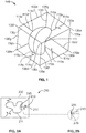
- FIG. 1 depicts a support frame 110 supporting an object 111 through a series of runners 113 a-d interconnected with struts 130 a-d.
- Object 111 may be a product or products awaiting post-processing treatment (e.g., sintering, heat treatment, machining, or the like) or a plurality of parts requiring assembly for a product (e.g., cube, shelf, part negative, or the like).
- Support frame 110 is configured to provide sufficient support for holding object 111 by at least partially surrounding object 111 after the PBAM process has finished and the support from the powder bed (not shown) has been removed.
- support frame 110 can be treated as a single body rather than multiple unconnected parts, allowing for larger batch quantities to be produced while reducing the risk of damage from unconnected parts contacting each other during the de-powdering process and when being handled by an operator for post processing. Further, support frame 110 may maintain object 111 in a preferred orientation, for instance in a manner ideal for post-processing treatments. For instance, support frame 110 may support object 111 suspended in a 3D space, as shown in FIG. 1 , or in a 2D plane, as shown in FIG. 7 , as discussed below.
- Struts 130 a-l are configured to form a geometric shape capable of maintaining its structural integrity while supporting object 111 during transport and post-processing treatment.
- FIG. 1 shows struts 130 a-l configured in a rectangular shape
- struts 130 a-l can be made in any geometric shape.
- struts 130a-l can be configured in the form of a scaffold, lattice, or some other 2D or 3D matrix known to one skilled in the art.
- struts 130 a-l are straight bars connecting with each other at each end to form strut connections 135 a-g.
- struts 130 can be other shapes and lengths.
- struts 130 may be straight, curved, angled, or any combination of the above. While struts 130 may be made of the same material as object 111-as struts 130 and object 111 are usually manufactured from the same powder bed-other embodiments may have struts 130 fabricated out of different material.
- Runners 113 a-d are integrally connected with the object 111 at object contact points 115 a-d and with struts 130 a-d at strut contact points 114 a-d.
- Strut contact points 114 a-d are chosen to provide maximal support and even distribution of force along the support frame 110 when holding object 111 while maintaining the structural integrity of support frame 110.
- strut contact points 114 may be placed at any point along the length of struts 130.
- Object contact points 115 a-d are chosen to provide sufficient support for object 111 during suspension while the tips of runners 113 a-d may be fabricated such that object contact points 115 a-d can be broken with minimal force and decreased risk of damage to object 111.
- an operator may remove object 111 from support frame 110 by applying sufficient torsion, shearing, or pulling force on object contact points 115 a-d such that object 111 may be detached from runners 113 a-d while runners 113 a-d remain connected to struts 130 a-d at strut contact points 114a-d.
- Runners 113 a-d can be straight, as seen in runner 113 d, or spring-like, as seen in runners 113a-c. Spring runners will be discussed in more detail in FIGS. 2A-B below.
- FIG. 1 shows four strut contact points 114 a-d and four object contact points 115 a-d, there can be more or less depending on the desired orientation and support for object 111. For instance, a plurality of strut contact points 114 may be created to stabilize a large or fragile object 111.
- Support frame 110 may be formed, at least in part, in a layer-by-layer fashion using an additive layer manufacturing (ALM), i.e. 3D printing, such as PBAM, which uses a high energy beam, such as a laser beam or an electron beam, to solidify or bind materials together.
- ALM processes preferably may be powder-bed based processes including selective laser sintering (SLS), selective laser melting (SLM), and electron beam melting (EBM), as disclosed in U.S. Patent Nos. 7,537,664 , 8,728,387 , 9,135,374 , 9,180,010 and 9,456,901 , U.S. Prov. Pat. App. No.
- support frame 110 is formed at the same time, utilizing the same process as object 111.
- support frame 210 including object 211 and struts 230 is provided, as described above.
- support frame 210 includes spring runners 213.
- Spring runners 213 are similar to runners 113 of FIG. 1 , except spring runners 213 have a non-linear shape, e.g., a curved, coiled, flat, clocked, or angled shape.
- Spring runners 213 are designed to hold object 211 in place while allowing for shrinkage during sintering or heat treatment as certain materials will experience deformation during those processes. This is especially important as shrinkage of a straight runner, as seen in runner 113 of FIG. 1 , can reduce the support provided to the manufactured object. In this manner, the amount of support provided by spring runners 213 to object 211 remains the same before and after post-processing treatment.
- Spring runners 213 may have any number of coils as deemed necessary, including having no coils and having only a curved or angled shape.
- FIG. 2B depicts a partial view of spring runner 213 being tapered starting from point 270 to object contact point 215. In this manner, the operator may detach object 211 with minimal force and risk of damage while still providing sufficient support for object 211 during transportation or post-process treatment.
- support frame 310 includes objects 311 a-d, strut 330, runners 313 a-d, and fixture points 316 a, b.
- support frame 310 includes fixture point 316 a connected to runners 313 a, b supporting objects 311 a, b and fixture point 316 b connected to runners 313 c, d supporting objects 311 c, d.
- An operator may grab onto one or multiple of fixture points 316 a, b when handling the support frame 310.
- FIGS. 4 and 5 depict other embodiments of a support frame including fixture points.
- FIG. 4 depicts a top view of a support frame 410 comprising fixture point 416 a connected to runners 413 a supporting objects 411 a.
- fixture point 416 b, runners 413 b, and objects 411 b mirrors fixture point 416 a, runners 413 a and object 413 a about point 470.
- weight may be equally distributed between fixture points 416 a and 416 b to allow for greater control and support when handling support frame 410.
- FIG. 5 depicts a side view of a support frame 510 comprising fixture point 516 connected to runners 513 a, d supporting objects 511 a, d.
- Objects 511 a, d are connected to objects 511 b, c by runners 513 b, c.
- Strut 530 connects to runners 513 b, c by strut connections 535 a, b. In this manner, strut 530 provides additional support for support frame 510 during transport and handling.
- the single fixture point 516 allows for increased ease of use by the operator or robot.
- support batch 600 including support frames 610 and 620 supporting objects 611 and 621, respectively, are provided.
- support frames 610 and 620 form support batch 600 through fixture point 616 and frame connection 645.
- Support frame 610 provides support for object 611 through spring runners 613 a, c and pronged runner 613 b.
- Pronged runner 613b connects to strut 330 by strut contact point 614 b while supporting the object with a plurality of object contact points 615 b. In this manner, the stress placed on contact points 615 a, c are more evenly distributed, allowing for greater support of object 611.
- Pronged runner 613 b is not limited to only one strut contact point 614 and, in other embodiments, may have any number of strut contact points 614 a, b, c and object contact points 615 a, b, c.
- Support frame 620 provides support for object 621 through runner 623. Where the object is sufficiently light, only one runner 623 may be required, thus reducing the material and cost required during manufacture.
- FIG. 6 shows support batch 600 having two support frames 610 and 620, any number of support frames may be provided, as shown in FIG. 7 , below.
- Fixture point 616 connects support frames 610 and 620 while providing a secure location for an operator to grab.
- fixture point 616 may be manufactured in a shape that is capable of carrying the weight of support batch 600 and ergonomically designed to be grasped, such as in the form of a handle or another structure designed to be grasped by a robot or the like.
- fixture point 616 may be manufactured in a location designed to most equally distribute the stress of support batch 600 when being lifted. In this manner, fixture point 616 may allow an operator to transport and handle support batch 600 with increased ease and greater security.
- a product may alternatively be performed by having an operator lift support batch 600 by fixture point 616 and removing the powder using vacuum or pressurized air. In this manner, the risk to damage to the product may be minimized.
- support batch 700 includes a plurality of support frames 710, 720, 732, 740, 750 connected to each other by strut connections 745 a-g.
- the support frames 710, 720, 732, 740, 750 are arranged in a 2D plane, each providing support for a corresponding object 711, 721, 731, 741, 751, respectively.
- support frame 710 provides support to object 711 through runners 713 a-d being connected to struts 730 a-d.
- support batch 700 may be one layer in a multi-layer stack of support batches comprising any number of layers. Further, support batch 700 may include any number of support frames, oriented in many different manners with respect to each other.
- Objects 711, 721, 731, 741, 751 may include both a part of a product and a support for that part. For instance, both a part of a product and a negative of that part, as described below, may be detached from support batch 700 to simplify the post-process treatment and assist in the protection of that part during treatment.
- support frame 800 including object 811, struts 830, and runners 813 a-d is provided, as described above.
- support frame 800 includes part negative 850.
- Part negative 850 is connected to object 811 through connectors 860, and to struts 830 through runners 813 c-d.
- Part negative 850 has a shape that is the opposite of object 811 such that, upon removal of connectors 860, object 811 would precisely fit on top of part negative 850. In this manner, part negative 850 may support object 811 by minimizing sagging or deformation to object 811 during post-processing.
- connectors 860 may either remain attached to object 811 and part negative 850, or removed from support frame 800.
- FIG. 8 shows three connectors 860, in other embodiments, there may be any number of connectors.
- FIG. 8 shows where connectors 860 is straight, connectors may take any shape, e.g., a curved, coiled, or angled shape.
- the negative does not have any connectors and is instead coated with a sintering inhibitor that has a higher melting point than the material of the negative (e.g. ceramic paint where the negative is a metal, or an alternative material).
- a sintering inhibitor that has a higher melting point than the material of the negative (e.g. ceramic paint where the negative is a metal, or an alternative material).
- the object would be allowed to sag onto the negative during prost-processing, allowing for the surface of the object to have a smoother finish.
- the negative is separately manufactured and attached to the support frame for each post-processing cycle.
- the separately attached negative may be made by a reusable material (e.g. solid ceramic, or the like) or a single use material (e.g. printed ceramic, or the like).
- support frame 100 in FIG. 1 may be utilized to support object 111 during transportation and post-processing.
- Support frame 100 may be manufactured by PBAM, BJAM, or some other method of additive manufacturing known to one skilled in the art. Once manufacturing has finished, the powder (not shown) surrounding support frame 100 may be removed by, for instance, pressurized air or vacuuming the area surrounding support frame 100 until no or minimal powder remains.
- Support frame 110 is then transported to a different station for further processing.
- An operator, robot, or the like may grasp onto supports 130 a-l and/or strut connections 135 to transport support frame 110.
- object 111 may be removed from support frame 110 by applying a torsion, shearing, or pulling force on object contact points 115 a-d such that object 111 is detached from runners 113 a-d while runners 113 a-d remain connected to struts 13 0a-d at strut contact points 114 a-d.
- object 111 may require further post-processing treatment after the de-powdering process.
- object 111 is not detached from support frame 110 after transportation. Rather, object 111 remains in a preferred orientation within support frame 110 and undergoes post-processing treatment, such as sintering, heat treatment, or machining. Once the post-processing treatment has been completed, object 111 may be detached from support frame 110, as described above.
- support batch 600 in FIG. 6 may be utilized to support objects 611 and 621 with support frames 610 and 620, respectively, during transportation and post-processing.
- Support batch 600 may be manufactured and de-powdered, as described above.
- an operator such as a robot or the like, may transport support batch 600 by grasping onto fixture point 616. Once support batch 600 has arrived at a desired location, objects 611 and 621 may be detached, or undergo post-processing treatment, as described above.
- fixture point 616 may be fabricated at a pre-determined and consistent location so that the robot may be programmed to grasp onto fixture point 616 and transport support batch 600 to a location for post-process treatment. After treatment has been finished, the robot transports support batch 600 by grasping onto fixture point 616, to a final processing location. The robot then detaches objects 611 and 621 by applying a pre-calculated amount of force on object contact points 615 a-c and 625. The robot may then return to its starting location and repeat the process again. In this manner, the entire post-processing treatment may be completed with minimal or no human operators.
- any of the embodiments described above and illustrated in the figures may be constructed of various different materials.
- metals such as titanium, or polymers, such as PEEK.
- Support frames and support batches may be fabricated from other various materials as well.
- the powder bed may be metal powders such as stainless steels, titanium alloy, nickel-based alloys (e.g., inconel), cobalt chromium, aluminum alloy, or the like.
- the laser used to solidify or bind the materials in PBAM may be an electron beam, a fiber-optic laser beam, a thermal print head, or the like. It is also contemplated to form different portions of the objects and support frames from different materials. For example, it is contemplated to form the latter from softer material that can easily be broken away from the former.
- the powder bed may be metal powders such as stainless steel, aluminum alloy, nickel alloys or iron alloys, ceramics such as silica sand or ceramic beads, polymers such as acrylonitrile butadiene styrene, polyamide or polycarbonate, or the like.
- BJAM binding agents may be, for instance, PM-B-SR-1-04 for binding metals, or any binding agent known to one skilled in the art.
- Support frames manufactured in a 3D space may be a part of a support frame matrix (not shown) having a plurality of support frames 110 adjacent to, and stacked on top of, each other.
- support frames and support batches manufactured in a 2D plane may be one or more layers in a multi-layer stack (not shown) having a plurality of layers of support batches 700 stacked on top of each other. In this manner, production capabilities may be maximized in a 3D space or 2D plane.
- Struts may provide clamping points (not shown). In this manner, the clamping points may provide a visual marker on struts 130 a-l indicating where support frame 110 may optimally be clamped to increase stability for post-process treatments that may involve destabilizing forces, such as machining. Additionally, struts, as shown in FIG. 1 , may include reference locations (not shown). In this manner, the reference locations may allow an operator to make accurate measurements of struts 130 a-l.
Abstract
Description
- The present application claims the benefit of, and priority to,
U.S. Provisional Patent Application Serial No. 62/789,152, filed on January 7, 2019 - Additive manufacturing is a type of 3D printing where products are fabricated with custom geometries by means of sequentially adding layers of material. One form of additive manufacturing is powder bed additive manufacturing ("PBAM"). During this process, a computer-controlled laser is directed into a layer of powder at pre-defined and specific points, forming a solid material at those points. A new layer of powder is then swept over the previous layer and the process is repeated until completion. Once the process is finished, the surrounding powder is removed, usually by vacuum or pressurized air, leaving the underlying products. The finished products are then individually and manually removed by an operator at which point they can be further processed, if necessary.
- PBAM provides several advantages over other types of 3D printing involving the use of a build platen, such as larger batch quantities, reduced build time, and reduced scrap. However, when the batch quantity becomes sufficiently large, individual handling of parts may become too difficult and unwieldy, especially where the batch involves a wide variety of different parts and custom geometries. For instance, the lack of product uniformity in the batch may increase the complexity and time taken to process the batch. Additionally, the risk of damage to the individual parts is increased from the operator de-powdering and handling the product for post-processing. All of this increases the inefficiencies in the build process.
- Moreover, during PBAM, the surrounding powder may provide structural support to the products as they are being manufactured. However, once the manufacturing is completed, and the excess powder is removed, the finished products may lack sufficient support. This can result in destabilization of the build and/or damage to the individual products. While external supports may be attached to the build plate during manufacturing, this can drastically increase the cost and complications of manufacturing where large batches of products are being fabricated, and may limit the diversity and complexity of products capable of being manufactured.
- Another form of additive manufacturing is binder jetting additive manufacturing ("BJAM"). During this process, a binding agent, such as glue, is deposited in a layer of powder, binding the powder at pre-determined and specific points, forming a solid material at those points. Similar to PBAM, above, a new layer of powder is then swept over the previous layer and the process is repeated until completion and de-powdered. At this point in the process, BJAM and its completed product have similar advantages as that of PBAM over other forms of additive manufacturing, including larger batch quantities, reduced build time, and reduced scrap.
- However, the same inefficiencies of PBAM are, when product batches become sufficiently large and complex, greatly exacerbated in BJAM. The finished product of BJAM is usually in a brittle state, having high porosity and weak mechanical properties, and requiring a post-processing treatment, such as sintering or infiltration. These post-processing treatments require the finished product to be transported and handled by an operator or machine while in that weakened, brittle state.
- Moreover, post-processing treatments usually require the binding agent to be burned out (leaving a porous product) before allowing the remaining material to bond together, as in sintering, or infiltrating the now porous product with an alternative material, such as bronze. During that state of temporarily increased porosity, the product is at an even greater risk of damage, and may require a specific orientation or suspension to avoid damage during post-process treatment. As such, structural support for the finished products is an even more critical consideration in the BJAM process.
- Therefore, there is a need for a support frame that reduces the difficulty and time required in processing large batches of products.
- Several different support frames, as well as methods of utilizing same, are disclosed herein. The support frames permit a multitude of products, such as orthopedic implants, to be formed and/or coated at a single given time through a binder jetting or powder bed fusion process.
- According to one embodiment, the support frame has a runner supporting an object. The runner provides structural support to the object and has a sufficiently small contact with the object to allow the object to be broken off the runners while leaving the runners attached to the support frame.
- In another embodiment, the support frame has a plurality of spring runners. The spring runners are designed to have a shape capable of compensating for deformation during post-process treatment, such as sintering or heat treatment.
- In another embodiment, a plurality of support frames are connected to form a support batch having a fixture point. The fixture point is located in a location permitting simplified handling of the support batch by an operator.
- In another embodiment, the support frame has a plurality of fixture points.
- In another embodiment, a plurality of support frames are connected in 2D space to form a support batch.
- In a further embodiment, a system for supporting an object created by additive manufacturing comprising the object, and a frame comprising at least one strut having a length and forming a shape at least partially surrounding the object, a runner having first and second ends, the first end integrally connected to a strut and the second end removably attached to the object. Further, the at least one strut may take the form of any one, or any combination, of straight, curved, or angled struts. Further, the runner may further comprise a first circumference and a second circumference, the first and second circumferences being different. Further, the second circumference may be smaller than the first circumference. Further, the at least one runner may take the form of any one, or any combination, of a curved, coiled, flat, clocked, or angled runner. Further, the at least one runner may be deformable upon being heated. Further, the at least one runner may provide the same amount of support before and after being deformed. Further, the at least one fixture may be located on a portion of the at least one frame and configured to interact with an operator. Further, the frame may further comprise a negative having a shape opposite the object. Further, the frame is a material may comprise any one or a combination of stainless steel, titanium, nickel, inconel, cobalt chromium, or aluminum.
- In a yet further embodiment, a method comprising binding a bed of powder to create an object, and a frame comprising forming a shape at least partially surrounding the object, at least one strut, and a runner having first and second ends, the first end integrally connected to the at least one strut and the second end removably attached to the object, and detaching the object from the frame. Further, the method may further comprise heating the at least one object. Further, the heating step may include a temperature between 100°C and 1400°C. Further, the method may further comprise transporting the frame to a location. Further, the method may further comprise combining the object with a material. Further, the method may further comprise attaching a negative having the opposite shape of the object to the frame.
- In a yet further embodiment, a method of forming a structure comprising the steps of placing a layer of powder on a substrate, partially fusing the powder at specific location to create a fused structure and an unfused structure, repeating the placing and fusing steps to create the structure and a frame at least partially surrounding and attached to the structure, and removing the structure from the frame. Further, the method may further comprise heating the fused structure. Further, the heating step includes a temperature between 100°C and 1400°C. Further, the method may further comprise moving the structure and frame by grabbing a portion of the frame. Further, the method may further comprise infusing the structure with a material. Further, the method may further comprise attaching a negative having the opposite shape of the object to the frame.
- These and other features, aspects, and advantages of the present invention will become better understood with regard to the following description, and accompanying drawings.
-
FIG. 1 is a perspective view of a support frame according to one embodiment of the present invention. -
FIG. 2A is a side view of a support frame with a plurality of spring runners according to another embodiment of the present invention. -
FIG. 2B is a partial view of the tip of one of the runners ofFIG. 2A . -
FIG. 3 is a side view of a support batch comprising a plurality of support frames supported by various types of runners according to another embodiment of the present invention. -
FIG. 4 is a side view of a support frame with a plurality of fixture points according to another embodiment of the present invention. -
FIG. 5 is a top view of an embodiment of the support frame ofFIG. 3 . -
FIG. 6 is a side view of another embodiment of the present invention. -
FIG. 7 is a top view of a support batch comprising a plurality of support frames in a 2D plane according to another embodiment of the present invention. -
FIG. 8 is a side view of a support frame comprising a part negative according to another embodiment of the present invention. -
FIG. 1 depicts asupport frame 110 supporting anobject 111 through a series of runners 113 a-d interconnected with struts 130 a-d.Object 111 may be a product or products awaiting post-processing treatment (e.g., sintering, heat treatment, machining, or the like) or a plurality of parts requiring assembly for a product (e.g., cube, shelf, part negative, or the like).Support frame 110 is configured to provide sufficient support for holdingobject 111 by at least partially surroundingobject 111 after the PBAM process has finished and the support from the powder bed (not shown) has been removed. In this manner,support frame 110 can be treated as a single body rather than multiple unconnected parts, allowing for larger batch quantities to be produced while reducing the risk of damage from unconnected parts contacting each other during the de-powdering process and when being handled by an operator for post processing. Further,support frame 110 may maintainobject 111 in a preferred orientation, for instance in a manner ideal for post-processing treatments. For instance,support frame 110 may supportobject 111 suspended in a 3D space, as shown inFIG. 1 , or in a 2D plane, as shown inFIG. 7 , as discussed below. - Struts 130 a-l are configured to form a geometric shape capable of maintaining its structural integrity while supporting
object 111 during transport and post-processing treatment. AlthoughFIG. 1 shows struts 130 a-l configured in a rectangular shape, struts 130 a-l can be made in any geometric shape. For instance, in other embodiments, struts 130a-l can be configured in the form of a scaffold, lattice, or some other 2D or 3D matrix known to one skilled in the art. In the embodiment shown inFIG. 1 , struts 130 a-l are straight bars connecting with each other at each end to form strut connections 135 a-g. In other embodiments, struts 130 can be other shapes and lengths. For instance, in other embodiments, struts 130 may be straight, curved, angled, or any combination of the above. While struts 130 may be made of the same material as object 111-as struts 130 and object 111 are usually manufactured from the same powder bed-other embodiments may have struts 130 fabricated out of different material. - Runners 113 a-d are integrally connected with the
object 111 at object contact points 115 a-d and with struts 130 a-d at strut contact points 114 a-d. Strut contact points 114 a-d are chosen to provide maximal support and even distribution of force along thesupport frame 110 when holdingobject 111 while maintaining the structural integrity ofsupport frame 110. In other embodiments, strut contact points 114 may be placed at any point along the length of struts 130. Object contact points 115 a-d are chosen to provide sufficient support forobject 111 during suspension while the tips of runners 113 a-d may be fabricated such that object contact points 115 a-d can be broken with minimal force and decreased risk of damage to object 111. In this manner, an operator may removeobject 111 fromsupport frame 110 by applying sufficient torsion, shearing, or pulling force on object contact points 115 a-d such thatobject 111 may be detached from runners 113 a-d while runners 113 a-d remain connected to struts 130 a-d at strut contact points 114a-d. Runners 113 a-d can be straight, as seen inrunner 113 d, or spring-like, as seen in runners 113a-c. Spring runners will be discussed in more detail inFIGS. 2A-B below. - Although
FIG. 1 shows four strut contact points 114 a-d and four object contact points 115 a-d, there can be more or less depending on the desired orientation and support forobject 111. For instance, a plurality of strut contact points 114 may be created to stabilize a large orfragile object 111. -
Support frame 110 may be formed, at least in part, in a layer-by-layer fashion using an additive layer manufacturing (ALM), i.e. 3D printing, such as PBAM, which uses a high energy beam, such as a laser beam or an electron beam, to solidify or bind materials together. Such ALM processes preferably may be powder-bed based processes including selective laser sintering (SLS), selective laser melting (SLM), and electron beam melting (EBM), as disclosed inU.S. Patent Nos. 7,537,664 ,8,728,387 ,9,135,374 9,180,010 9,456,901 U.S. Prov. Pat. App. No. 62/517,456 62/520,221 U.S. Pat. App. No. 15/982,704 ,15/277,744 14/276,483 14/969,695 support frame 110 is formed at the same time, utilizing the same process asobject 111. - In another embodiment, illustrated in
FIG. 2A ,support frame 210 includingobject 211 and struts 230 is provided, as described above. In this embodiment,support frame 210 includesspring runners 213.Spring runners 213 are similar to runners 113 ofFIG. 1 , exceptspring runners 213 have a non-linear shape, e.g., a curved, coiled, flat, clocked, or angled shape.Spring runners 213 are designed to holdobject 211 in place while allowing for shrinkage during sintering or heat treatment as certain materials will experience deformation during those processes. This is especially important as shrinkage of a straight runner, as seen in runner 113 ofFIG. 1 , can reduce the support provided to the manufactured object. In this manner, the amount of support provided byspring runners 213 to object 211 remains the same before and after post-processing treatment.Spring runners 213 may have any number of coils as deemed necessary, including having no coils and having only a curved or angled shape. -
FIG. 2B depicts a partial view ofspring runner 213 being tapered starting frompoint 270 to objectcontact point 215. In this manner, the operator may detachobject 211 with minimal force and risk of damage while still providing sufficient support forobject 211 during transportation or post-process treatment. - In another embodiment, illustrated in
FIG. 3 ,support frame 310 includes objects 311 a-d, strut 330, runners 313 a-d, and fixture points 316 a, b. In this embodiment,support frame 310 includesfixture point 316 a connected torunners 313 a,b supporting objects 311 a, b andfixture point 316 b connected torunners 313 c,d supporting objects 311 c, d. An operator may grab onto one or multiple of fixture points 316 a, b when handling thesupport frame 310.FIGS. 4 and 5 , below, depict other embodiments of a support frame including fixture points. -
FIG. 4 depicts a top view of asupport frame 410 comprisingfixture point 416 a connected torunners 413 a supportingobjects 411 a. In this embodiment,fixture point 416 b,runners 413 b, and objects 411 bmirrors fixture point 416 a,runners 413 a and object 413 a aboutpoint 470. In this manner, weight may be equally distributed between fixture points 416 a and 416 b to allow for greater control and support when handlingsupport frame 410. -
FIG. 5 depicts a side view of asupport frame 510 comprisingfixture point 516 connected torunners 513 a,d supporting objects 511 a, d.Objects 511 a, d are connected toobjects 511 b, c byrunners 513 b, c.Strut 530 connects torunners 513 b, c bystrut connections 535 a, b. In this manner, strut 530 provides additional support forsupport frame 510 during transport and handling. Thesingle fixture point 516 allows for increased ease of use by the operator or robot. - In another embodiment, illustrated in
FIG. 6 ,support batch 600 including support frames 610 and 620 supportingobjects form support batch 600 throughfixture point 616 andframe connection 645.Support frame 610 provides support forobject 611 throughspring runners 613 a, c andpronged runner 613 b.Pronged runner 613b connects to strut 330 bystrut contact point 614 b while supporting the object with a plurality of object contact points 615 b. In this manner, the stress placed oncontact points 615 a, c are more evenly distributed, allowing for greater support ofobject 611.Pronged runner 613 b is not limited to only one strut contact point 614 and, in other embodiments, may have any number of strut contact points 614 a, b, c and object contact points 615 a, b, c.Support frame 620 provides support forobject 621 throughrunner 623. Where the object is sufficiently light, only onerunner 623 may be required, thus reducing the material and cost required during manufacture. AlthoughFIG. 6 showssupport batch 600 having two support frames 610 and 620, any number of support frames may be provided, as shown inFIG. 7 , below. -
Fixture point 616 connects support frames 610 and 620 while providing a secure location for an operator to grab. For instance,fixture point 616 may be manufactured in a shape that is capable of carrying the weight ofsupport batch 600 and ergonomically designed to be grasped, such as in the form of a handle or another structure designed to be grasped by a robot or the like. Additionally,fixture point 616 may be manufactured in a location designed to most equally distribute the stress ofsupport batch 600 when being lifted. In this manner,fixture point 616 may allow an operator to transport and handlesupport batch 600 with increased ease and greater security. For instance, rather than de-powdering a product by handling it directly-thus increasing the risk of damage to the product-de-powdering a product may alternatively be performed by having an operatorlift support batch 600 byfixture point 616 and removing the powder using vacuum or pressurized air. In this manner, the risk to damage to the product may be minimized. - In another embodiment, illustrated in
FIG. 7 ,support batch 700 includes a plurality of support frames 710, 720, 732, 740, 750 connected to each other by strut connections 745 a-g. In this embodiment, the support frames 710, 720, 732, 740, 750 are arranged in a 2D plane, each providing support for acorresponding object support frame 710 provides support to object 711 through runners 713 a-d being connected to struts 730 a-d. Runners 713 a-d are connected to object 711 and struts 730 a-d through object contact points 715 a-d on a first end and to struts 730 a-d through strut contact points 714 a-d on a second end, respectively. Although not shown,support batch 700 may be one layer in a multi-layer stack of support batches comprising any number of layers. Further,support batch 700 may include any number of support frames, oriented in many different manners with respect to each other. -
Objects support batch 700 to simplify the post-process treatment and assist in the protection of that part during treatment. - In another embodiment, illustrated in
FIG. 8 ,support frame 800 includingobject 811, struts 830, and runners 813 a-d is provided, as described above. In this embodiment,support frame 800 includes part negative 850. Part negative 850 is connected to object 811 throughconnectors 860, and tostruts 830 through runners 813 c-d. Part negative 850 has a shape that is the opposite ofobject 811 such that, upon removal ofconnectors 860,object 811 would precisely fit on top of part negative 850. In this manner, part negative 850 may supportobject 811 by minimizing sagging or deformation to object 811 during post-processing. Moreover, during post-processing,connectors 860 may either remain attached to object 811 and part negative 850, or removed fromsupport frame 800. AlthoughFIG. 8 shows threeconnectors 860, in other embodiments, there may be any number of connectors. Additionally, althoughFIG. 8 shows whereconnectors 860 is straight, connectors may take any shape, e.g., a curved, coiled, or angled shape. - In another embodiment, the negative does not have any connectors and is instead coated with a sintering inhibitor that has a higher melting point than the material of the negative (e.g. ceramic paint where the negative is a metal, or an alternative material). In this manner, the object would be allowed to sag onto the negative during prost-processing, allowing for the surface of the object to have a smoother finish.
- In another embodiment, the negative is separately manufactured and attached to the support frame for each post-processing cycle. The separately attached negative may be made by a reusable material (e.g. solid ceramic, or the like) or a single use material (e.g. printed ceramic, or the like).
- In addition to that described above and illustrated in the figures, various other operations will now be described. It should be understood that the following operations do not have to be performed in the exact order described below. Instead, various steps may be handled in a different order or simultaneously. Steps may also be omitted or added unless otherwise stated therein.
- In an embodiment of use, support frame 100 in
FIG. 1 may be utilized to supportobject 111 during transportation and post-processing. Support frame 100 may be manufactured by PBAM, BJAM, or some other method of additive manufacturing known to one skilled in the art. Once manufacturing has finished, the powder (not shown) surrounding support frame 100 may be removed by, for instance, pressurized air or vacuuming the area surrounding support frame 100 until no or minimal powder remains. -
Support frame 110 is then transported to a different station for further processing. An operator, robot, or the like may grasp onto supports 130 a-l and/or strut connections 135 to transportsupport frame 110. Once the operator has arrived at a desired location withsupport frame 110,object 111 may be removed fromsupport frame 110 by applying a torsion, shearing, or pulling force on object contact points 115 a-d such thatobject 111 is detached from runners 113 a-d while runners 113 a-d remain connected to struts 13 0a-d at strut contact points 114 a-d. - In another method of use of
support frame 110,object 111 may require further post-processing treatment after the de-powdering process. In this embodiment,object 111 is not detached fromsupport frame 110 after transportation. Rather, object 111 remains in a preferred orientation withinsupport frame 110 and undergoes post-processing treatment, such as sintering, heat treatment, or machining. Once the post-processing treatment has been completed,object 111 may be detached fromsupport frame 110, as described above. - In another method of use,
support batch 600 inFIG. 6 may be utilized to supportobjects Support batch 600 may be manufactured and de-powdered, as described above. In this embodiment, an operator, such as a robot or the like, may transportsupport batch 600 by grasping ontofixture point 616. Oncesupport batch 600 has arrived at a desired location, objects 611 and 621 may be detached, or undergo post-processing treatment, as described above. - In the case of the use of a robot,
fixture point 616 may be fabricated at a pre-determined and consistent location so that the robot may be programmed to grasp ontofixture point 616 andtransport support batch 600 to a location for post-process treatment. After treatment has been finished, the robot transportssupport batch 600 by grasping ontofixture point 616, to a final processing location. The robot then detachesobjects - It is to be understood that any of the embodiments described above and illustrated in the figures, may be constructed of various different materials. For instance, it is contemplated to utilize metals, such as titanium, or polymers, such as PEEK. Support frames and support batches may be fabricated from other various materials as well. For instance, using PBAM, the powder bed may be metal powders such as stainless steels, titanium alloy, nickel-based alloys (e.g., inconel), cobalt chromium, aluminum alloy, or the like. The laser used to solidify or bind the materials in PBAM may be an electron beam, a fiber-optic laser beam, a thermal print head, or the like. It is also contemplated to form different portions of the objects and support frames from different materials. For example, it is contemplated to form the latter from softer material that can easily be broken away from the former.
- With BJAM, the powder bed may be metal powders such as stainless steel, aluminum alloy, nickel alloys or iron alloys, ceramics such as silica sand or ceramic beads, polymers such as acrylonitrile butadiene styrene, polyamide or polycarbonate, or the like. BJAM binding agents may be, for instance, PM-B-SR-1-04 for binding metals, or any binding agent known to one skilled in the art.
- Support frames manufactured in a 3D space, as shown in
FIG. 1 , may be a part of a support frame matrix (not shown) having a plurality of support frames 110 adjacent to, and stacked on top of, each other. Additionally, support frames and support batches manufactured in a 2D plane, as shown inFIG. 7 , may be one or more layers in a multi-layer stack (not shown) having a plurality of layers ofsupport batches 700 stacked on top of each other. In this manner, production capabilities may be maximized in a 3D space or 2D plane. - Struts, as shown in
FIG. 1 , may provide clamping points (not shown). In this manner, the clamping points may provide a visual marker on struts 130 a-l indicating wheresupport frame 110 may optimally be clamped to increase stability for post-process treatments that may involve destabilizing forces, such as machining. Additionally, struts, as shown inFIG. 1 , may include reference locations (not shown). In this manner, the reference locations may allow an operator to make accurate measurements of struts 130 a-l. - Although the invention herein has been described with reference to particular embodiments, it is to be understood that these embodiments are merely illustrative of the principles and applications of the present invention. It is therefore to be understood that numerous modifications may be made to the illustrative embodiments and that other arrangements may be devised without departing from the scope of the present invention as defined by the appended claims.
Claims (15)
- A system for supporting an object created by additive manufacturing comprising:the object; anda frame forming a shape at least partially surrounding the object having:at least one strut; anda runner having a first and second end, the first end integrally connected to the at least one strut and the second end removably attached to the object.
- The system of claim 1, wherein the at least one strut has a form of any one, or any combination, of straight, curved, or angled struts.
- The system of any one of claims 1 to 2, wherein the runner further comprises a first circumference and a second circumference, the first and second circumferences being different.
- The system of any one of claims 1 to 3, wherein the runner has a form of any one, or any combination, of a curved, coiled, flat, clocked, or angled runner.
- The system of claim 4, wherein the runner is deformable upon being heated.
- The system of claim 5, wherein the runner provides a same amount of support before and after being deformed.
- The system of any one of claims 1 to 6, further comprising a fixture located on a portion of the frame and configured to be interacted with by an operator.
- The system of any one of claims 1 to 7, wherein the frame further comprises a negative having an opposite shape of the object.
- A method comprising:binding a bed of powder to create:an object; anda frame comprising forming a shape at least partially surrounding the object, the object having:at least one strut; anda runner having first and second ends, the first end integrally connected to the at least one strut and the second end removably attached to the object; anddetaching the object from the frame.
- The method of claim 9, further comprising heating the object to a temperature between 100°C and 1400°C.
- The method of any one of claims 9 to 10, further comprising combining the object with a material.
- The method of any one of claims 9 to 11, further comprising attaching a negative having an opposite shape of the object to the frame.
- A method of forming a structure comprising the steps of:placing a layer of powder on a substrate;partially fusing a location on the layer of powder to create a fused structure and an unfused structure along the layer of powder;repeating the placing and fusing steps to create, from the fused structure, an object and a frame at least partially surrounding and attached to the object; andremoving the object from the frame.
- The method of claim 13, further comprising infusing the object with a material.
- The method of any one of claims 13 to 14, further comprising attaching to the frame a negative having an opposite shape of the object.
Applications Claiming Priority (1)
| Application Number | Priority Date | Filing Date | Title |
|---|---|---|---|
| US201962789152P | 2019-01-07 | 2019-01-07 |
Publications (2)
| Publication Number | Publication Date |
|---|---|
| EP3677363A1 true EP3677363A1 (en) | 2020-07-08 |
| EP3677363B1 EP3677363B1 (en) | 2022-12-07 |
Family
ID=69147484
Family Applications (1)
| Application Number | Title | Priority Date | Filing Date |
|---|---|---|---|
| EP20150587.2A Active EP3677363B1 (en) | 2019-01-07 | 2020-01-07 | Support frame |
Country Status (3)
| Country | Link |
|---|---|
| US (1) | US20200215610A1 (en) |
| EP (1) | EP3677363B1 (en) |
| AU (1) | AU2020200077B2 (en) |
Families Citing this family (3)
| Publication number | Priority date | Publication date | Assignee | Title |
|---|---|---|---|---|
| WO2021015795A1 (en) * | 2019-07-25 | 2021-01-28 | Hewlett-Packard Development Company, L.P. | Object model data modification for three dimensional printers |
| US20220152933A1 (en) * | 2019-07-29 | 2022-05-19 | Hewlett-Packard Development Company, L.P. | Object geometry for three dimensional printers |
| WO2021084484A2 (en) | 2019-10-29 | 2021-05-06 | Stryker European Operations Limited | Surgical navigation tracker, system, and method |
Citations (8)
| Publication number | Priority date | Publication date | Assignee | Title |
|---|---|---|---|---|
| EP2022622A1 (en) * | 2007-08-10 | 2009-02-11 | Rolls-Royce plc | Support architecture |
| US7537664B2 (en) | 2002-11-08 | 2009-05-26 | Howmedica Osteonics Corp. | Laser-produced porous surface |
| US20120018926A1 (en) * | 2010-07-22 | 2012-01-26 | Stratasys, Inc. | Three-Dimensional Parts Having Porous Protective Structures |
| US8728387B2 (en) | 2005-12-06 | 2014-05-20 | Howmedica Osteonics Corp. | Laser-produced porous surface |
| US9135374B2 (en) | 2012-04-06 | 2015-09-15 | Howmedica Osteonics Corp. | Surface modified unit cell lattice structures for optimized secure freeform fabrication |
| US9180010B2 (en) | 2012-04-06 | 2015-11-10 | Howmedica Osteonics Corp. | Surface modified unit cell lattice structures for optimized secure freeform fabrication |
| US9456901B2 (en) | 2004-12-30 | 2016-10-04 | Howmedica Osteonics Corp. | Laser-produced porous structure |
| WO2018151720A1 (en) * | 2017-02-15 | 2018-08-23 | Hewlett-Packard Development Company, L.P. | Product framing |
Family Cites Families (3)
| Publication number | Priority date | Publication date | Assignee | Title |
|---|---|---|---|---|
| US6270335B2 (en) * | 1995-09-27 | 2001-08-07 | 3D Systems, Inc. | Selective deposition modeling method and apparatus for forming three-dimensional objects and supports |
| DE102014203386A1 (en) * | 2014-02-25 | 2015-08-27 | Siemens Aktiengesellschaft | Powder bed-based additive manufacturing process, in which a support structure is used for the production of the component |
| US20180311732A1 (en) * | 2017-04-28 | 2018-11-01 | Divergent Technologies, Inc. | Support structures in additive manufacturing |
-
2020
- 2020-01-06 US US16/734,590 patent/US20200215610A1/en not_active Abandoned
- 2020-01-06 AU AU2020200077A patent/AU2020200077B2/en active Active
- 2020-01-07 EP EP20150587.2A patent/EP3677363B1/en active Active
Patent Citations (8)
| Publication number | Priority date | Publication date | Assignee | Title |
|---|---|---|---|---|
| US7537664B2 (en) | 2002-11-08 | 2009-05-26 | Howmedica Osteonics Corp. | Laser-produced porous surface |
| US9456901B2 (en) | 2004-12-30 | 2016-10-04 | Howmedica Osteonics Corp. | Laser-produced porous structure |
| US8728387B2 (en) | 2005-12-06 | 2014-05-20 | Howmedica Osteonics Corp. | Laser-produced porous surface |
| EP2022622A1 (en) * | 2007-08-10 | 2009-02-11 | Rolls-Royce plc | Support architecture |
| US20120018926A1 (en) * | 2010-07-22 | 2012-01-26 | Stratasys, Inc. | Three-Dimensional Parts Having Porous Protective Structures |
| US9135374B2 (en) | 2012-04-06 | 2015-09-15 | Howmedica Osteonics Corp. | Surface modified unit cell lattice structures for optimized secure freeform fabrication |
| US9180010B2 (en) | 2012-04-06 | 2015-11-10 | Howmedica Osteonics Corp. | Surface modified unit cell lattice structures for optimized secure freeform fabrication |
| WO2018151720A1 (en) * | 2017-02-15 | 2018-08-23 | Hewlett-Packard Development Company, L.P. | Product framing |
Also Published As
| Publication number | Publication date |
|---|---|
| EP3677363B1 (en) | 2022-12-07 |
| AU2020200077A1 (en) | 2020-07-23 |
| AU2020200077B2 (en) | 2024-04-18 |
| US20200215610A1 (en) | 2020-07-09 |
Similar Documents
| Publication | Publication Date | Title |
|---|---|---|
| EP3677363A1 (en) | Support frame | |
| EP2022622B1 (en) | Method of forming a support architecture | |
| JP6746308B2 (en) | Hybrid additive manufacturing method using hybrid additive manufactured features for hybrid parts | |
| US20210178746A1 (en) | Articles and structures prepared by three-dimensional printing method | |
| CN106141181B (en) | Additive manufacturing on 3-D components | |
| EP0529816B1 (en) | Method and apparatus for fabrication of three-dimensional articles by weld deposition | |
| CN106041075B (en) | A kind of high energy beam increasing material manufacturing method of metal parts hanging structure | |
| US9505176B2 (en) | Method for producing three-dimensional components | |
| US5203944A (en) | Method for fabrication of three-dimensional articles by thermal spray deposition using masks as support structures | |
| CN104985180B (en) | A kind of intermetallic compound and preparation method thereof and equipment | |
| JP2014508857A5 (en) | ||
| US20210154732A1 (en) | Distortion mitigation in directed energy deposition | |
| US20180214946A1 (en) | Layerwise material application method and apparatus for additive manufacturing | |
| EP3682987A1 (en) | System and method for fabricating an object | |
| KR102542961B1 (en) | 3D printing method | |
| US20210276096A1 (en) | Distortion mitigation in directed energy deposition | |
| US7344608B2 (en) | Method and apparatus for heat-treating an article and a fixture for use in the same | |
| CN111688203A (en) | Manufacturing device and method for additive manufacturing of a component with a protruding part of material | |
| EP3677362A1 (en) | Binder jet shell | |
| JP6774623B2 (en) | Manufacturing method of materials for turbine blades | |
| EP3427869A1 (en) | Additive manufacturing methods and related components | |
| US20230234878A1 (en) | Glass handling devices and related methods | |
| JP4781858B2 (en) | Manufacturing method of sintered products | |
| Udroiu | Additive Manufacturing Technologies Used for Superalloys Processing | |
| Bento | Evaluation of Mechanical Properties of Fused Filament Fabrication 3D Printed Parts |
Legal Events
| Date | Code | Title | Description |
|---|---|---|---|
| PUAI | Public reference made under article 153(3) epc to a published international application that has entered the european phase |
Free format text: ORIGINAL CODE: 0009012 |
|
| STAA | Information on the status of an ep patent application or granted ep patent |
Free format text: STATUS: REQUEST FOR EXAMINATION WAS MADE |
|
| 17P | Request for examination filed |
Effective date: 20200107 |
|
| AK | Designated contracting states |
Kind code of ref document: A1 Designated state(s): AL AT BE BG CH CY CZ DE DK EE ES FI FR GB GR HR HU IE IS IT LI LT LU LV MC MK MT NL NO PL PT RO RS SE SI SK SM TR |
|
| AX | Request for extension of the european patent |
Extension state: BA ME |
|
| STAA | Information on the status of an ep patent application or granted ep patent |
Free format text: STATUS: EXAMINATION IS IN PROGRESS |
|
| 17Q | First examination report despatched |
Effective date: 20210517 |
|
| REG | Reference to a national code |
Ref country code: DE Ref legal event code: R079 Ref document number: 602020006689 Country of ref document: DE Free format text: PREVIOUS MAIN CLASS: B22F0003105000 Ipc: B33Y0010000000 |
|
| RIC1 | Information provided on ipc code assigned before grant |
Ipc: B33Y 80/00 20150101ALI20220726BHEP Ipc: B33Y 40/20 20200101ALI20220726BHEP Ipc: B29C 64/245 20170101ALI20220726BHEP Ipc: B22F 10/40 20210101ALI20220726BHEP Ipc: B22F 10/20 20210101ALI20220726BHEP Ipc: B22F 10/10 20210101ALI20220726BHEP Ipc: B22F 5/00 20060101ALI20220726BHEP Ipc: B22F 3/24 20060101ALI20220726BHEP Ipc: B33Y 10/00 20150101AFI20220726BHEP |
|
| INTG | Intention to grant announced |
Effective date: 20220905 |
|
| RIN1 | Information on inventor provided before grant (corrected) |
Inventor name: WESTNOTT, KEVIN Inventor name: ROBINSON, JOSEPH Inventor name: KENNY, MARK Inventor name: HEARNE, TOMMY |
|
| GRAS | Grant fee paid |
Free format text: ORIGINAL CODE: EPIDOSNIGR3 |
|
| STAA | Information on the status of an ep patent application or granted ep patent |
Free format text: STATUS: GRANT OF PATENT IS INTENDED |
|
| GRAA | (expected) grant |
Free format text: ORIGINAL CODE: 0009210 |
|
| STAA | Information on the status of an ep patent application or granted ep patent |
Free format text: STATUS: THE PATENT HAS BEEN GRANTED |
|
| AK | Designated contracting states |
Kind code of ref document: B1 Designated state(s): AL AT BE BG CH CY CZ DE DK EE ES FI FR GB GR HR HU IE IS IT LI LT LU LV MC MK MT NL NO PL PT RO RS SE SI SK SM TR |
|
| REG | Reference to a national code |
Ref country code: GB Ref legal event code: FG4D |
|
| REG | Reference to a national code |
Ref country code: CH Ref legal event code: EP Ref country code: AT Ref legal event code: REF Ref document number: 1536078 Country of ref document: AT Kind code of ref document: T Effective date: 20221215 |
|
| REG | Reference to a national code |
Ref country code: DE Ref legal event code: R096 Ref document number: 602020006689 Country of ref document: DE |
|
| REG | Reference to a national code |
Ref country code: IE Ref legal event code: FG4D |
|
| REG | Reference to a national code |
Ref country code: LT Ref legal event code: MG9D |
|
| REG | Reference to a national code |
Ref country code: NL Ref legal event code: MP Effective date: 20221207 |
|
| PG25 | Lapsed in a contracting state [announced via postgrant information from national office to epo] |
Ref country code: SE Free format text: LAPSE BECAUSE OF FAILURE TO SUBMIT A TRANSLATION OF THE DESCRIPTION OR TO PAY THE FEE WITHIN THE PRESCRIBED TIME-LIMIT Effective date: 20221207 Ref country code: NO Free format text: LAPSE BECAUSE OF FAILURE TO SUBMIT A TRANSLATION OF THE DESCRIPTION OR TO PAY THE FEE WITHIN THE PRESCRIBED TIME-LIMIT Effective date: 20230307 Ref country code: LT Free format text: LAPSE BECAUSE OF FAILURE TO SUBMIT A TRANSLATION OF THE DESCRIPTION OR TO PAY THE FEE WITHIN THE PRESCRIBED TIME-LIMIT Effective date: 20221207 Ref country code: FI Free format text: LAPSE BECAUSE OF FAILURE TO SUBMIT A TRANSLATION OF THE DESCRIPTION OR TO PAY THE FEE WITHIN THE PRESCRIBED TIME-LIMIT Effective date: 20221207 Ref country code: ES Free format text: LAPSE BECAUSE OF FAILURE TO SUBMIT A TRANSLATION OF THE DESCRIPTION OR TO PAY THE FEE WITHIN THE PRESCRIBED TIME-LIMIT Effective date: 20221207 |
|
| REG | Reference to a national code |
Ref country code: AT Ref legal event code: MK05 Ref document number: 1536078 Country of ref document: AT Kind code of ref document: T Effective date: 20221207 |
|
| PG25 | Lapsed in a contracting state [announced via postgrant information from national office to epo] |
Ref country code: RS Free format text: LAPSE BECAUSE OF FAILURE TO SUBMIT A TRANSLATION OF THE DESCRIPTION OR TO PAY THE FEE WITHIN THE PRESCRIBED TIME-LIMIT Effective date: 20221207 Ref country code: PL Free format text: LAPSE BECAUSE OF FAILURE TO SUBMIT A TRANSLATION OF THE DESCRIPTION OR TO PAY THE FEE WITHIN THE PRESCRIBED TIME-LIMIT Effective date: 20221207 Ref country code: LV Free format text: LAPSE BECAUSE OF FAILURE TO SUBMIT A TRANSLATION OF THE DESCRIPTION OR TO PAY THE FEE WITHIN THE PRESCRIBED TIME-LIMIT Effective date: 20221207 Ref country code: HR Free format text: LAPSE BECAUSE OF FAILURE TO SUBMIT A TRANSLATION OF THE DESCRIPTION OR TO PAY THE FEE WITHIN THE PRESCRIBED TIME-LIMIT Effective date: 20221207 Ref country code: GR Free format text: LAPSE BECAUSE OF FAILURE TO SUBMIT A TRANSLATION OF THE DESCRIPTION OR TO PAY THE FEE WITHIN THE PRESCRIBED TIME-LIMIT Effective date: 20230308 |
|
| PGFP | Annual fee paid to national office [announced via postgrant information from national office to epo] |
Ref country code: DE Payment date: 20221213 Year of fee payment: 4 |
|
| P01 | Opt-out of the competence of the unified patent court (upc) registered |
Effective date: 20230522 |
|
| PG25 | Lapsed in a contracting state [announced via postgrant information from national office to epo] |
Ref country code: NL Free format text: LAPSE BECAUSE OF FAILURE TO SUBMIT A TRANSLATION OF THE DESCRIPTION OR TO PAY THE FEE WITHIN THE PRESCRIBED TIME-LIMIT Effective date: 20221207 |
|
| PG25 | Lapsed in a contracting state [announced via postgrant information from national office to epo] |
Ref country code: SM Free format text: LAPSE BECAUSE OF FAILURE TO SUBMIT A TRANSLATION OF THE DESCRIPTION OR TO PAY THE FEE WITHIN THE PRESCRIBED TIME-LIMIT Effective date: 20221207 Ref country code: RO Free format text: LAPSE BECAUSE OF FAILURE TO SUBMIT A TRANSLATION OF THE DESCRIPTION OR TO PAY THE FEE WITHIN THE PRESCRIBED TIME-LIMIT Effective date: 20221207 Ref country code: PT Free format text: LAPSE BECAUSE OF FAILURE TO SUBMIT A TRANSLATION OF THE DESCRIPTION OR TO PAY THE FEE WITHIN THE PRESCRIBED TIME-LIMIT Effective date: 20230410 Ref country code: EE Free format text: LAPSE BECAUSE OF FAILURE TO SUBMIT A TRANSLATION OF THE DESCRIPTION OR TO PAY THE FEE WITHIN THE PRESCRIBED TIME-LIMIT Effective date: 20221207 Ref country code: CZ Free format text: LAPSE BECAUSE OF FAILURE TO SUBMIT A TRANSLATION OF THE DESCRIPTION OR TO PAY THE FEE WITHIN THE PRESCRIBED TIME-LIMIT Effective date: 20221207 Ref country code: AT Free format text: LAPSE BECAUSE OF FAILURE TO SUBMIT A TRANSLATION OF THE DESCRIPTION OR TO PAY THE FEE WITHIN THE PRESCRIBED TIME-LIMIT Effective date: 20221207 |
|
| PG25 | Lapsed in a contracting state [announced via postgrant information from national office to epo] |
Ref country code: SK Free format text: LAPSE BECAUSE OF FAILURE TO SUBMIT A TRANSLATION OF THE DESCRIPTION OR TO PAY THE FEE WITHIN THE PRESCRIBED TIME-LIMIT Effective date: 20221207 Ref country code: IS Free format text: LAPSE BECAUSE OF FAILURE TO SUBMIT A TRANSLATION OF THE DESCRIPTION OR TO PAY THE FEE WITHIN THE PRESCRIBED TIME-LIMIT Effective date: 20230407 Ref country code: AL Free format text: LAPSE BECAUSE OF FAILURE TO SUBMIT A TRANSLATION OF THE DESCRIPTION OR TO PAY THE FEE WITHIN THE PRESCRIBED TIME-LIMIT Effective date: 20221207 |
|
| REG | Reference to a national code |
Ref country code: CH Ref legal event code: PL |
|
| REG | Reference to a national code |
Ref country code: DE Ref legal event code: R097 Ref document number: 602020006689 Country of ref document: DE |
|
| PG25 | Lapsed in a contracting state [announced via postgrant information from national office to epo] |
Ref country code: MC Free format text: LAPSE BECAUSE OF FAILURE TO SUBMIT A TRANSLATION OF THE DESCRIPTION OR TO PAY THE FEE WITHIN THE PRESCRIBED TIME-LIMIT Effective date: 20221207 Ref country code: LU Free format text: LAPSE BECAUSE OF NON-PAYMENT OF DUE FEES Effective date: 20230107 |
|
| REG | Reference to a national code |
Ref country code: BE Ref legal event code: MM Effective date: 20230131 |
|
| PLBE | No opposition filed within time limit |
Free format text: ORIGINAL CODE: 0009261 |
|
| STAA | Information on the status of an ep patent application or granted ep patent |
Free format text: STATUS: NO OPPOSITION FILED WITHIN TIME LIMIT |
|
| PG25 | Lapsed in a contracting state [announced via postgrant information from national office to epo] |
Ref country code: LI Free format text: LAPSE BECAUSE OF NON-PAYMENT OF DUE FEES Effective date: 20230131 Ref country code: DK Free format text: LAPSE BECAUSE OF FAILURE TO SUBMIT A TRANSLATION OF THE DESCRIPTION OR TO PAY THE FEE WITHIN THE PRESCRIBED TIME-LIMIT Effective date: 20221207 Ref country code: CH Free format text: LAPSE BECAUSE OF NON-PAYMENT OF DUE FEES Effective date: 20230131 |
|
| 26N | No opposition filed |
Effective date: 20230908 |
|
| PG25 | Lapsed in a contracting state [announced via postgrant information from national office to epo] |
Ref country code: SI Free format text: LAPSE BECAUSE OF FAILURE TO SUBMIT A TRANSLATION OF THE DESCRIPTION OR TO PAY THE FEE WITHIN THE PRESCRIBED TIME-LIMIT Effective date: 20221207 Ref country code: BE Free format text: LAPSE BECAUSE OF NON-PAYMENT OF DUE FEES Effective date: 20230131 |
|
| PGFP | Annual fee paid to national office [announced via postgrant information from national office to epo] |
Ref country code: GB Payment date: 20231130 Year of fee payment: 5 |
|
| PGFP | Annual fee paid to national office [announced via postgrant information from national office to epo] |
Ref country code: IE Payment date: 20231211 Year of fee payment: 5 Ref country code: FR Payment date: 20231212 Year of fee payment: 5 |