EP3677296B1 - Microjet drug injection device equipped with backflow prevention valve - Google Patents
Microjet drug injection device equipped with backflow prevention valve Download PDFInfo
- Publication number
- EP3677296B1 EP3677296B1 EP18852169.4A EP18852169A EP3677296B1 EP 3677296 B1 EP3677296 B1 EP 3677296B1 EP 18852169 A EP18852169 A EP 18852169A EP 3677296 B1 EP3677296 B1 EP 3677296B1
- Authority
- EP
- European Patent Office
- Prior art keywords
- drug
- injection
- backflow prevention
- prevention valve
- lower housing
- Prior art date
- Legal status (The legal status is an assumption and is not a legal conclusion. Google has not performed a legal analysis and makes no representation as to the accuracy of the status listed.)
- Active
Links
Images


Classifications
-
- A—HUMAN NECESSITIES
- A61—MEDICAL OR VETERINARY SCIENCE; HYGIENE
- A61M—DEVICES FOR INTRODUCING MEDIA INTO, OR ONTO, THE BODY; DEVICES FOR TRANSDUCING BODY MEDIA OR FOR TAKING MEDIA FROM THE BODY; DEVICES FOR PRODUCING OR ENDING SLEEP OR STUPOR
- A61M5/00—Devices for bringing media into the body in a subcutaneous, intra-vascular or intramuscular way; Accessories therefor, e.g. filling or cleaning devices, arm-rests
- A61M5/178—Syringes
- A61M5/20—Automatic syringes, e.g. with automatically actuated piston rod, with automatic needle injection, filling automatically
- A61M5/2053—Media being expelled from injector by pressurised fluid or vacuum
-
- A—HUMAN NECESSITIES
- A61—MEDICAL OR VETERINARY SCIENCE; HYGIENE
- A61M—DEVICES FOR INTRODUCING MEDIA INTO, OR ONTO, THE BODY; DEVICES FOR TRANSDUCING BODY MEDIA OR FOR TAKING MEDIA FROM THE BODY; DEVICES FOR PRODUCING OR ENDING SLEEP OR STUPOR
- A61M39/00—Tubes, tube connectors, tube couplings, valves, access sites or the like, specially adapted for medical use
- A61M39/22—Valves or arrangement of valves
- A61M39/24—Check- or non-return valves
-
- A—HUMAN NECESSITIES
- A61—MEDICAL OR VETERINARY SCIENCE; HYGIENE
- A61M—DEVICES FOR INTRODUCING MEDIA INTO, OR ONTO, THE BODY; DEVICES FOR TRANSDUCING BODY MEDIA OR FOR TAKING MEDIA FROM THE BODY; DEVICES FOR PRODUCING OR ENDING SLEEP OR STUPOR
- A61M5/00—Devices for bringing media into the body in a subcutaneous, intra-vascular or intramuscular way; Accessories therefor, e.g. filling or cleaning devices, arm-rests
- A61M5/14—Infusion devices, e.g. infusing by gravity; Blood infusion; Accessories therefor
- A61M5/142—Pressure infusion, e.g. using pumps
-
- A—HUMAN NECESSITIES
- A61—MEDICAL OR VETERINARY SCIENCE; HYGIENE
- A61M—DEVICES FOR INTRODUCING MEDIA INTO, OR ONTO, THE BODY; DEVICES FOR TRANSDUCING BODY MEDIA OR FOR TAKING MEDIA FROM THE BODY; DEVICES FOR PRODUCING OR ENDING SLEEP OR STUPOR
- A61M5/00—Devices for bringing media into the body in a subcutaneous, intra-vascular or intramuscular way; Accessories therefor, e.g. filling or cleaning devices, arm-rests
- A61M5/14—Infusion devices, e.g. infusing by gravity; Blood infusion; Accessories therefor
- A61M5/168—Means for controlling media flow to the body or for metering media to the body, e.g. drip meters, counters ; Monitoring media flow to the body
-
- A—HUMAN NECESSITIES
- A61—MEDICAL OR VETERINARY SCIENCE; HYGIENE
- A61M—DEVICES FOR INTRODUCING MEDIA INTO, OR ONTO, THE BODY; DEVICES FOR TRANSDUCING BODY MEDIA OR FOR TAKING MEDIA FROM THE BODY; DEVICES FOR PRODUCING OR ENDING SLEEP OR STUPOR
- A61M5/00—Devices for bringing media into the body in a subcutaneous, intra-vascular or intramuscular way; Accessories therefor, e.g. filling or cleaning devices, arm-rests
- A61M5/178—Syringes
- A61M5/30—Syringes for injection by jet action, without needle, e.g. for use with replaceable ampoules or carpules
- A61M5/3007—Syringes for injection by jet action, without needle, e.g. for use with replaceable ampoules or carpules with specially designed jet passages at the injector's distal end
-
- A—HUMAN NECESSITIES
- A61—MEDICAL OR VETERINARY SCIENCE; HYGIENE
- A61M—DEVICES FOR INTRODUCING MEDIA INTO, OR ONTO, THE BODY; DEVICES FOR TRANSDUCING BODY MEDIA OR FOR TAKING MEDIA FROM THE BODY; DEVICES FOR PRODUCING OR ENDING SLEEP OR STUPOR
- A61M5/00—Devices for bringing media into the body in a subcutaneous, intra-vascular or intramuscular way; Accessories therefor, e.g. filling or cleaning devices, arm-rests
- A61M5/14—Infusion devices, e.g. infusing by gravity; Blood infusion; Accessories therefor
- A61M2005/1401—Functional features
- A61M2005/1406—Minimizing backflow along the delivery catheter track
-
- A—HUMAN NECESSITIES
- A61—MEDICAL OR VETERINARY SCIENCE; HYGIENE
- A61M—DEVICES FOR INTRODUCING MEDIA INTO, OR ONTO, THE BODY; DEVICES FOR TRANSDUCING BODY MEDIA OR FOR TAKING MEDIA FROM THE BODY; DEVICES FOR PRODUCING OR ENDING SLEEP OR STUPOR
- A61M39/00—Tubes, tube connectors, tube couplings, valves, access sites or the like, specially adapted for medical use
- A61M39/22—Valves or arrangement of valves
- A61M39/24—Check- or non-return valves
- A61M2039/2406—Check- or non-return valves designed to quickly shut upon the presence of back-pressure
Definitions
- the present invention relates to a microjet drug injection device equipped with a backflow prevention valve, and more particularly, to a microjet drug injection device equipped with a backflow prevention valve, which is equipped with a backflow prevention valve on the side of a lower housing in which a drug is filled, such that fluid is moved in one direction, thereby preventing the introduction of external air into the lower housing through an injection nozzle.
- drug delivery methods such as needleless syringes are being developed, and as a part of this research, drug delivery methods in which a drug is injected rapidly using a microjet method and penetrated directly into the body through the epidermis of skin are proposed.
- the laser-bubble microjet injection method applies a phenomenon that bubbles are generated by the collapse of a liquid structure when a strong energy such as a laser beam is concentrated in a liquid in a closed chamber. As the bubbles are generated and grown in the liquid in the closed space as described above, the total volume increases, and thus, an elastic membrane forming one side of the chamber is rapidly extended to the outside to push a drug solution out of a nozzle, thereby causing microjet injection.
- Korean Patent No. 10-1207977 discloses a microjet drug delivery system.
- KR 101 684 250 B1 discloses a needleless drug delivery system.
- the needleless drug delivery system is described to enhance durability of a membrane that partitions a space to fill a drug by reinforcing a weak portion of the membrane or by forming a double membrane.
- KR 10 2014 0086919 A relates to static pressure and a metering pump, the pump having a hollow interior and allowing a fluid to flow only in one direction, in which when pressure is applied to the pump, the internal volume decreases and a positive pressure is generated, and when the pressure is removed, the internal volume increases due to the elastic restoring power of the pump and a negative pressure is generated.
- KR 10 2007 0018725 A discloses a method for making a jet injection drug delivery device wherein the drug delivery device has at least one drug reservoir and at least one injection nozzle.
- the method is described to include identifying a drug desired to be delivered, identifying a volume of the drug desired to be delivered, establishing a reservoir diameter for the at least one drug reservoir, establishing a nozzle diameter for the at least one injection nozzle, identifying a tissue model for delivery of the drug, identifying a penetration depth in the tissue model for the delivery of the drug, and injecting the drug into the tissue model under variable pressure until the desired penetration depth is achieved.
- WO 2014/025241 A1 discloses a transdermal drug delivery system for delivering medication through the skin.
- a microjet drug delivery system is described to comprise a pressure chamber which has a predetermined accommodating space and which has a sealed interior sealingly filled with water serving as a liquid for generating pressure, a drug chamber which is arranged in the vicinity of the pressure chamber so as to accommodate a drug solution in a predetermined accommodating space thereof, and which has, on one side thereof, a micronozzle for jetting the drug solution to the outside in mircojets, an elastic membrane interposed between the pressure chamber and the micro-drug chamber, and a laser unit for emitting a laser beam onto the liquid for generating pressure stored in the pressure chamber so as to generate bubbles in the liquid in order to generate pressure.
- US 5 840 061 A discloses an ejection apparatus for the high pressure ejection of a liquid.
- the apparatus is described to include (a) a pressure chamber for containing the liquid, (b) an ejection opening communicating between an outside and an inside of the pressure chamber, (c) a working piston displaceable in the pressure chamber from a first position at a beginning of a working stroke to second position at an end of the working stroke, and (d) a drive for driving the working piston.
- KR 101 052 669 B1 discloses an injector without a needle for injecting drug using an epidermal layer of animal, and an amount of the drug to scan from a medicine case is inhaled to the inside of a scanner with an operation of repetitively pulling a lever and the drug within the scanner is automatically scanned with the operation of pulling the trigger.
- the present invention is directed to a microjet drug injection device equipped with a backflow prevention valve for preventing external air from entering a lower housing through an injection nozzle and for automatically supplying a drug by providing a backflow prevention valve on the side of the lower housing to which a drug is filled to move fluid in one direction.
- a drug injection device is equipped with a backflow prevention valve
- the drug injection device comprises an upper housing sealed at one side of a pressure partition formed to surround the side and providing a floodlight lens at the sealed side; a lower housing comprising a drug partition formed to surround a side surface and an injection nozzle extending from the drug partition and comprising an injection path of drugs formed at a lower portion of the injection nozzle , wherein the lower housing is connected to or is extended from the upper housing; a compartment provided between the upper housing and the lower housing and partitioning a space in which a pressure generating liquid is filled in the upper housing and a space in which a drug is filled in the lower housing, and transmitting pressure acting on the space filled with the pressure generating liquid to the space in which a drug is filled; and a backflow prevention valve formed of an elastic material, wherein an upper side is provided in a lower side in the lower housing to be in close contact with the lower housing, an open circular inlet is formed on the upper side and the shape of the cross section,
- the backflow prevention valve is provided with a lower end cross-section and a slit shaped "C".
- an inner material of the "C" shape has lower elastic modulus than an outer material of the "C" shape.
- the backflow prevention valve is provided with a lower end cross-section and a slit shaped "+".
- the microjet drug injection device comprises a plurality of injection paths.
- the injection paths are provided in a regular polygonal arrangement.
- an inner wall forming the injection path is formed of a ceramic material.
- diameter of the injection path is 50 micrometers to 250 micrometers.
- the shape of a lower end cross-section and a slit of the backflow prevention valve may be "C" shaped, whereby a sealing force may be increased and durability may be increased as compared with a case where the cross-section and the slit are straight.
- an inner material of the "C" shape of the backflow prevention valve is made of a material whose elastic modulus is less than that of an outer material, the slit may be opened more easily.
- the shape of the lower end cross-section and the slit of the backflow prevention valve may be "+" shaped, whereby a sealing force may be increased and durability may be increased as compared with the case where the cross-section and the slit are straight.
- the slit may be located close to an injection path and a drug may be pushed out at more uniform pressure.
- a procedure time may be shortened when multiple injections are required in an affected area.
- drugs may be injected into the body at equal intervals.
- an inner wall of the injection path with a ceramic material, it is possible to improve durability by preventing the end of the injection path from being broken or deformed during the microjet injection.
- a diameter of the injection path to 50 to 250 micrometers, it is possible to minimize drug bounce off the surface of the skin while maintaining a sufficient skin injection depth of a drug.
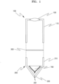
- FIG. 1 is a view of an exploded concept of a microjet drug injection device equipped with a backflow prevention valve, according to an embodiment of the present invention.
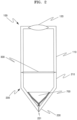
- FIG. 2 is a view of a concept of assembling the microjet drug injection device of FIG. 1 .
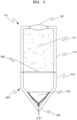
- FIG. 3 is a view of a concept in which a pressure generating liquid is filled in the microjet drug injection device of FIG. 2 .
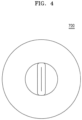
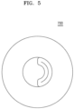
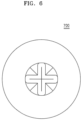
- FIGS. 4 to 6 are plan views from below of each embodiment of a backflow prevention valve of FIG. 3 .
- FIG. 7 is a plan view from below of an injection nozzle of FIG. 3 .
- FIG. 8 is a view of a concept in which an energy intensive device is added to FIG. 3 .
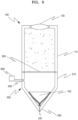
- FIG. 9 is a view of a concept in which a drug supply unit is added to FIG. 3 .
- the microjet drug injection device equipped with a backflow prevention valve includes an upper housing 100 equipped with a floodlight lens 120, a lower housing 200, a compartment 300, and a backflow prevention valve 700, wherein a pressure generating liquid 101 is filled and sealed in a space on the side of the floodlight lens 120, and a drug filled in a space on the side of an injection nozzle 230 is injected to the injection nozzle 230 by pressure due to expansion of the pressure generating liquid 101.
- the upper housing 100 is sealed at one side (upper side) of the pressure partition 110 formed to surround a side surface, and the floodlight lens 120 is provided at the sealed side.
- the upper housing 100 is to form a closed space in which the pressure generating liquid 101 is filled, and forms a closed space in which the pressure generating liquid 101 is filled by blocking a side by the pressure partition 110, by blocking one side (the upper side in FIGS. 1 to 3 ) provided with the floodlight lens 120, and by blocking the other side by the partition 300 to be described later below.
- FIGS. 1 to 3 show an example in which the floodlight lens 120 is expressed in a convex shape and blocks a portion of one side of the pressure partition 110, but the present invention is not limited thereto.
- the floodlight lens 120 may have various shapes such as a planar shape and a concave shape. It is also possible to block the whole of one side of the pressure partition 110 with only the floodlight lens 120.
- Normal water may be used as the pressure generating liquid 101, and various liquid materials such as polymer sol and gel such as alcohol or polyethylene glycol may be used.
- a degassed liquid may be preferably used as the pressure generating liquid 101 in order to minimize residual bubbles in generating bubbles.
- an electrolyte salt, etc.
- molecules are ionized to reduce the energy required for the collapse of a molecular structure of a liquid, which is more preferable because bubbles may be formed with better efficiency.
- the lower housing 200 includes a drug partition 210 formed to surround a side surface of the lower housing 200 and the injection nozzle 230 extending from the drug partition 210 and including an injection path 231 of drugs formed at a lower portion of the injection nozzle 230.
- the lower housing 200 is connected to or extended with the upper housing 100.
- the lower housing 200 is for forming a space in which a drug is filled, and the drug partition 210, the injection nozzle 230, and the compartment 300 block other portions except the injection path 231 of drugs to form a space in which a drug is filled.
- the injection nozzle 230 refers to a portion in which the injection path 231 of drugs is formed, and may be all or a part of the inclined portion shown in FIGS. 1 to 3 .
- the upper housing 100 and the lower housing 200 may be integrally formed, or may be formed to be separated and coupled.
- the injection nozzle 230 may be provided to be detachable to the lower housing 200.
- the injection nozzle 230 is provided detachably to the lower housing 200, when the injection nozzle 230 is broken, contaminated, or clogged, it can be solved simply by replacing only the injection nozzle 230 without replacing the entire lower housing 200, which is advantageous in terms of cost.
- Materials of a lower portion and a side portion of the lower housing 200 including the injection nozzle 230 may be variously selected as long as there is no problem in achieving the functions of the present invention, such as stellite, an aluminum alloy, and a zirconium-based ceramic material. Only a part of the lower portion of the lower housing 200 in which the injection path 231 is formed may be made of the zirconium-based ceramic material through insert injection.
- zirconium oxide zirconia
- zirconium oxide zirconia
- the lower housing 200, the injection nozzle 230, or the injection path 231 is formed of zirconium oxide (zirconia) in zirconium-based ceramic materials.
- the lower housing 200 or the inside of the injection nozzle 230 has a larger horizontal cross-sectional area toward the upper side in some or all sections, and may include a plurality of sections in which inclination of an inner wall is constant for each predetermined section, but the inclination of the inner wall decreases toward the upper direction.
- the lower housing 200 or the inside of the injection nozzle 230 may be provided in a trumpet shape that extends in a curved shape toward the compartment 300 from the injection path 231 in some or all sections.
- the lower housing 200 or the inside of the injection nozzle 230 may further concentrate on pushing a drug into the injection path 231 by pressure transmitted from the compartment 300. Accordingly, the drug injected into the injection path 231 may obtain a larger injection speed.
- the compartment 300 is provided between the upper housing 100 and the lower housing 200 and partitions a space in which a pressure generating liquid is filled of the upper housing 100 and a space in which a drug is filled of the lower housing 200, and transmits pressure acting on the space filled with the pressure generating liquid to the space in which a drug is filled.
- the compartment 300 partitions the upper housing 100 and the lower housing 200 to form a closed space in which the pressure generating liquid 101 is filled on one side of the compartment 300 (upper side of the compartment 300 of FIG. 2 ).
- the compartment 300 is preferably interposed in a portion where the upper housing 100 and the lower housing 200 are connected to each other (see FIGS. 1 to 3 ).
- the compartment 300 may be provided between the upper housing 100 and the lower housing 200, and may be formed of an elastic material that partitions the upper housing 100 and the lower housing 200.
- the compartment 300 may be made of silicon rubber or the like.
- the compartment 300 may be damaged first around the edge and the center due to rapid expansion. Therefore, the partition 300 preferably reinforces the edge and the center in preparation for rapid expansion.
- the compartment 300 is a film formed of an elastic material, but the present invention is not limited thereto. If a plate-shaped disk is configured in the form of reciprocating up and down and may transmit the pressure acting on the space filled with the pressure generating liquid to the space in which a drug is filled, various implementations are possible.
- the backflow prevention valve 700 is formed of an elastic (rubber) material, wherein the upper side is provided in a lower side of the lower housing 200 to be in close contact with the lower housing 200, and an open circular inlet is formed on the upper side and the shape of the cross section, as the cross section goes downward, becomes gradually narrower as it changes from circular to linear.
- a lower end of the backflow prevention valve 700 is formed with a slit through which a drug passes, allowing fluid to move only toward the injection nozzle 230.
- the backflow prevention valve 700 allows the flow of fluid (liquid, gas, etc.) to flow in only one direction, and may be partially or entirely formed in a shape in which an entrance is closed like a duck's beak or a flute spout.
- the backflow prevention valve 700 by allowing the drug filled in the lower housing 200 to be injected to the outside through the injection path 231 but preventing external air from being introduced through the injection path 231, may prevent the drug from being contaminated by preventing the external air from being mixed with the drug filled in the lower housing 200.
- the slit of the backflow prevention valve 700 is normally kept closed.
- the slit remains closed while a drug is filled in the lower housing 200. Subsequently, when the compartment 300 transmits the pressure to the side filled with a drug by the expansion of the pressure generating liquid 101, the slit is opened and the drug is injected through the injection path 231 by the pressure.
- the slit is closed by a restoring force (elastic force) of the backflow prevention valve 700 to prevent fluid from being sucked from the outside.
- a linear shape in which the slit is closed may be applied to a straight line (see FIG. 3 ), a curve (see FIG. 4 ), an intersection line (see FIG. 5 ), etc.
- the backflow prevention valve 700 of the microjet drug injection device equipped with a backflow prevention valve according to an embodiment of the present invention may be characterized in that the lower end cross-section and the slit are "C" shaped.
- a sealing force may be increased so that the slit does not normally open as compared with the case where the cross-section and the slit are straight.
- the shape of the lower end cross-section and the slit are "C" shape
- durability may be increased to increase the period of time that the slit does not normally open even if the slit is used continuously for a longer time as compared with the case where the shape of the cross section and the slit is a straight shape.
- the lower portion of the backflow prevention valve 700 may be characterized in that an inner material of the "C" shape has lower elastic modulus than an outer material of the "C" shape.
- the ratio of elastic modulus of the inner material of the "C” shape and the outer material of the "C” shape is preferably about 0.6 to about 0.9: 1.
- the backflow prevention valve 700 of the microjet drug injection device equipped with a backflow prevention valve according to an embodiment of the present invention may be characterized in that the lower end cross-section and the slit are "+" shaped.
- a sealing force may be increased so that the slit does not normally open as compared with the case where the cross-section and the slit are straight.
- the center of the slit may be on the extension line of the injection path 231 to minimize the maximum length of the slit so that the slit may be located near the injection path 231.
- the injection nozzle 230 may push a drug at a more uniform pressure to each injection path 231.
- durability may be increased to increase the period of time that the slit does not normally open even if the slit is used continuously for a longer time as compared with the case where the shape of the cross section and the slit is a straight shape.
- the injection path 231 of the microjet drug injection device equipped with a backflow prevention valve according to an embodiment of the present invention may be plural.
- the plurality of injection paths 231 may be provided in the lower portion of the lower housing 200. That is, only one injection path 231 may be provided, but two or more injection paths 231 may also be provided.
- the number of injection paths 231 may be preferably 2 to 9.
- an upper portion of each of the injection paths 231 may be formed in a tapered shape in which a horizontal cross-sectional area becomes narrower from the upper side to the lower side.
- the microjet drug injection device provided with a backflow prevention valve according to an embodiment of the present invention having the plurality of injection paths 231 as described above is highly desirable because the microjet drug injection device may shorten a procedure time by injecting a drug into a wide area by a single microjet injection when several injections are required in a wide area.
- the injection paths 231 of the microjet drug injection device equipped with a backflow prevention valve according to an embodiment of the present invention may be provided in a regular polygonal arrangement.
- the plurality of injection paths 231 may be provided in a regular polygonal arrangement such that the distance between neighboring injection paths 231 is constant, and thus drugs may be injected into the body at equal intervals during microjet injection.
- FIG. 7 illustrates an example in which four injection paths 231 are provided in a square arrangement
- the present invention is not limited thereto, and various embodiments such as rhombus forms are possible if the injection is possible at equal intervals.
- An inner wall forming the injection path 231 of the microjet drug injection device equipped with a backflow prevention valve according to an embodiment of the present invention may be formed of a zirconium-based ceramic material (zirconia).
- the inner wall forming the injection path 231 may be formed of a zirconium-based ceramic material and is preferably formed of zirconium oxide (zirconia). This is because, as mentioned above, zirconium oxide has high burst toughness and very high resistance to crack propagation, thereby preventing the end of the injection path 231 from being broken or deformed during the microjet injection.
- zirconium oxide has high burst toughness and very high resistance to crack propagation, thereby preventing the end of the injection path 231 from being broken or deformed during the microjet injection.
- the injection nozzle 230 formed of the zirconium-based ceramic material is provided to be detachable from the lower housing 200, and thus when the injection nozzle 230 provided with the injection path 231 is broken or when a change in the diameter of the injection path 231 is required, the injection nozzle 230 may be separated from the lower housing 200 so as to be replaced.
- a diameter of the injection path 231 of the microjet drug injection device equipped with a backflow prevention valve according to an embodiment of the present invention may be 50 micrometers to 250 micrometers.
- the diameter of the injection path 231 When the diameter of the injection path 231 is less than 50 micrometers, the amount of drug to be injected is small and the drug is not injected into the body to a sufficient depth. When the diameter of the injection path 231 exceeds 250 micrometers, the diameter of a microjet to which the drug is injected may increase, thereby increasing the amount of drug that is bounced off the surface of the skin and increasing the waste of the drug.
- the injection path 231 of drugs is formed to a diameter of 250 ⁇ m or less, even if a drug is filled in a space to be filled with a drug, if no pressure is applied above a certain level, the drug cannot escape through the injection path 231 of drugs.
- the microjet drug injection device provided with a backflow prevention valve may further include the energy intensive device 500 that concentrates energy toward a specific point in a closed space filled with the pressure generating liquid 101.
- the energy intensive device 500 refers to a device capable of concentrating energy using a microwave, a laser beam, or the like.
- the energy concentrator 500 concentrates energy such as a laser beam in the pressure generating liquid 101 to push a drug into the injection path 231 of drugs by instantaneous volume expansion (pressure increase) due to evaporation of the pressure generating liquid 101 and delivery of shock waves, thereby generating a microjet.
- the drug supply unit 600 connected to the drug supplement 220 may be used to replenish a drug to the space to be filled with a drug.
- the drug supply unit 600 may replenish a drug at a certain pressure at which a drug does not exit the injection path 231 of drugs.
- a drug is filled.
- a drug may be filled at a level that does not push the drug from the injection path 231 of drugs.
- a drug is introduced into the lower housing 200 from the drug supply unit 600 through the drug supplement 220, and the drug in the lower housing 200 may be discharged to the outside through the injection path 231 to be injected in the form of a microjet.
- a drug may be refilled by a reduced pressure as the drug is injected.
- a drug may be automatically charged without a separate power supply or separate control.
- all or a part of the inside of the lower housing 200 or the injection nozzle 230 may be formed in a tapered shape in which a horizontal cross-sectional area decreases from the compartment 300 toward the injection path 231. Through this, a pressure of the compartment 300 is concentrated in the injection path 231 to increase the injection speed of a microjet.
- the present invention relates to a microjet drug injection device equipped with a backflow prevention valve, and may be usefully used in the art.
Landscapes
- Health & Medical Sciences (AREA)
- Heart & Thoracic Surgery (AREA)
- Hematology (AREA)
- Engineering & Computer Science (AREA)
- Anesthesiology (AREA)
- Biomedical Technology (AREA)
- Life Sciences & Earth Sciences (AREA)
- Animal Behavior & Ethology (AREA)
- General Health & Medical Sciences (AREA)
- Public Health (AREA)
- Veterinary Medicine (AREA)
- Vascular Medicine (AREA)
- Pulmonology (AREA)
- Infusion, Injection, And Reservoir Apparatuses (AREA)
- Check Valves (AREA)
Description
- The present invention relates to a microjet drug injection device equipped with a backflow prevention valve, and more particularly, to a microjet drug injection device equipped with a backflow prevention valve, which is equipped with a backflow prevention valve on the side of a lower housing in which a drug is filled, such that fluid is moved in one direction, thereby preventing the introduction of external air into the lower housing through an injection nozzle.
- As a method of parenteral administration of therapeutic drugs in a patient's body, various drug delivery methods have been applied since ancient times. The most commonly used method for such a drug delivery system is a method using syringes. However, syringes have been feared by patients due to pain during injection, and have inevitable problems such as fear of infection due to wounds.
- To solve this problem, drug delivery methods such as needleless syringes are being developed, and as a part of this research, drug delivery methods in which a drug is injected rapidly using a microjet method and penetrated directly into the body through the epidermis of skin are proposed.
- For the high speed injection of such a microjet method, it is necessary to precisely and strongly inject a drug to the outside (i.e., skin). Such injection methods have been developed in various ways since the 1930s, and recently, various injection methods such as an injection method using a piezoelectric ceramic element, an injection method through a shock wave caused by applying a laser beam to an aluminum foil, and an injection method using a Lorentz force have been developed. In addition, unlike conventional microjet injection, a laser-bubble microjet injection method capable of continuously injecting and reusing while finely controlling the amount of drug to be injected and the injection speed of a drug (i.e., a penetration depth of the drug).
- The laser-bubble microjet injection method applies a phenomenon that bubbles are generated by the collapse of a liquid structure when a strong energy such as a laser beam is concentrated in a liquid in a closed chamber. As the bubbles are generated and grown in the liquid in the closed space as described above, the total volume increases, and thus, an elastic membrane forming one side of the chamber is rapidly extended to the outside to push a drug solution out of a nozzle, thereby causing microjet injection.
- However, there is a problem in that external air is introduced through the nozzle from which a drug is injected after the injection of the drug to contaminate the remaining drug.
-
Korean Patent No. 10-1207977 -
KR 101 684 250 B1 -
KR 10 2014 0086919 A -
KR 10 2007 0018725 A -
US 6 063 053 A discloses a needle-less injector. In the document the needle-less injector is described to comprise a housing containing the liquid medication, a driver that forces the medication out of the orifice of the injection end of the housing at a sufficient speed to deliver the medication to the skin of the patient, and an at least partially external resistance sensitive trigger operatively coupled to the driver and the trigger portion of the housing. -
WO 2014/025241 A1 discloses a transdermal drug delivery system for delivering medication through the skin. In the document a microjet drug delivery system is described to comprise a pressure chamber which has a predetermined accommodating space and which has a sealed interior sealingly filled with water serving as a liquid for generating pressure, a drug chamber which is arranged in the vicinity of the pressure chamber so as to accommodate a drug solution in a predetermined accommodating space thereof, and which has, on one side thereof, a micronozzle for jetting the drug solution to the outside in mircojets, an elastic membrane interposed between the pressure chamber and the micro-drug chamber, and a laser unit for emitting a laser beam onto the liquid for generating pressure stored in the pressure chamber so as to generate bubbles in the liquid in order to generate pressure. -
US 5 840 061 A discloses an ejection apparatus for the high pressure ejection of a liquid. In the document the apparatus is described to include (a) a pressure chamber for containing the liquid, (b) an ejection opening communicating between an outside and an inside of the pressure chamber, (c) a working piston displaceable in the pressure chamber from a first position at a beginning of a working stroke to second position at an end of the working stroke, and (d) a drive for driving the working piston. - Document D8 (
WO 2011/126569 A1 ) discloses a sealed delivery system for dispensing metered volumes of a pure or sterile flowable substance. In the document a handheld sealed delivery system is described to comprise a continuously sealing one-way valve assembly at a distal end, and a volume reducing reservoir at a proximal end, wherein the pure or sterile flowable substance can be stored in the volume reducing reservoir. In operation, a user pushes down upon a push button driven actuator assembly, acting upon a metering pumping chamber, which is in fluid communication with the pure or sterile flowable substance stored in the volume reducing reservoir via a check valve. Depression of the push button driven actuator causes a dispensing pump to push a metered volume of flowable substance through the continuously sealing one way dispensing valve assembly. -
KR 101 052 669 B1 - The present invention is directed to a microjet drug injection device equipped with a backflow prevention valve for preventing external air from entering a lower housing through an injection nozzle and for automatically supplying a drug by providing a backflow prevention valve on the side of the lower housing to which a drug is filled to move fluid in one direction.
- The objects of the one or more embodiments are not limited to the following description, and it should be understood by one of ordinary skill in the art that other objects not described here may be clearly understood from the following descriptions.
- The invention is defined in claim 1. Advantageous embodiments are subject of the dependent claims.
- According to an aspect of the present invention, a drug injection device is equipped with a backflow prevention valve, the drug injection device comprises an upper housing sealed at one side of a pressure partition formed to surround the side and providing a floodlight lens at the sealed side; a lower housing comprising a drug partition formed to surround a side surface and an injection nozzle extending from the drug partition and comprising an injection path of drugs formed at a lower portion of the injection nozzle , wherein the lower housing is connected to or is extended from the upper housing; a compartment provided between the upper housing and the lower housing and partitioning a space in which a pressure generating liquid is filled in the upper housing and a space in which a drug is filled in the lower housing, and transmitting pressure acting on the space filled with the pressure generating liquid to the space in which a drug is filled; and a backflow prevention valve formed of an elastic material, wherein an upper side is provided in a lower side in the lower housing to be in close contact with the lower housing, an open circular inlet is formed on the upper side and the shape of the cross section, as the cross section goes downward, becomes gradually narrower as it changes from circular to linear, a lower end of the backflow prevention valve is formed with a slit through which a drug passes, allowing fluid to move only toward the injection nozzle, a pressure generating liquid is filled and sealed in a space on the side of the floodlight lens, and a drug filled in the space on the side of an injection nozzle is injected to the injection nozzle by pressure due to expansion of the pressure generating liquid.
- According to an example embodiment the backflow prevention valve is provided with a lower end cross-section and a slit shaped "C".
- According to an example embodiment, in a lower portion of the backflow prevention valve, an inner material of the "C" shape has lower elastic modulus than an outer material of the "C" shape.
- According to an example embodiment, the backflow prevention valve is provided with a lower end cross-section and a slit shaped "+".
- According to an example embodiment, the microjet drug injection device comprises a plurality of injection paths.
- According to an example embodiment, the injection paths are provided in a regular polygonal arrangement.
- According to an example embodiment, an inner wall forming the injection path is formed of a ceramic material.
- According to an example embodiment, diameter of the injection path is 50 micrometers to 250 micrometers.
- According to a drug injection device equipped with a backflow prevention valve of an embodiment of the present invention, external air may be prevented from flowing into a lower housing through an injection nozzle, and a drug may be automatically supplied after drug injection by providing a backflow prevention valve in a lower side of the lower housing to move fluid in one direction.
- In addition, the shape of a lower end cross-section and a slit of the backflow prevention valve may be "C" shaped, whereby a sealing force may be increased and durability may be increased as compared with a case where the cross-section and the slit are straight.
- In addition, since an inner material of the "C" shape of the backflow prevention valve is made of a material whose elastic modulus is less than that of an outer material, the slit may be opened more easily.
- In addition, the shape of the lower end cross-section and the slit of the backflow prevention valve may be "+" shaped, whereby a sealing force may be increased and durability may be increased as compared with the case where the cross-section and the slit are straight. Also, the slit may be located close to an injection path and a drug may be pushed out at more uniform pressure.
- In addition, by providing a plurality of injection paths, a procedure time may be shortened when multiple injections are required in an affected area.
- In addition, by arranging the injection paths in a regular polygonal arrangement, drugs may be injected into the body at equal intervals.
- In addition, by forming an inner wall of the injection path with a ceramic material, it is possible to improve durability by preventing the end of the injection path from being broken or deformed during the microjet injection.
- In addition, by setting a diameter of the injection path to 50 to 250 micrometers, it is possible to minimize drug bounce off the surface of the skin while maintaining a sufficient skin injection depth of a drug.
-
-
FIG. 1 is a view of an exploded concept of a microjet drug injection device equipped with a backflow prevention valve, according to an embodiment of the present invention. -
FIG. 2 is a view of a concept of assembling the microjet drug injection device ofFIG. 1 . -
FIG. 3 is a view of a concept in which a pressure generating liquid is filled in the microjet drug injection device ofFIG. 2 . -
FIGS. 4 to 6 are plan views from below of each embodiment of a backflow prevention valve ofFIG. 3 . -
FIG. 7 is a plan view from below of an injection nozzle ofFIG. 3 . -
FIG. 8 is a view of a concept in which an energy intensive device is added toFIG. 3 . -
FIG. 9 is a view of a concept in which a drug supply unit is added toFIG. 3 . -
- 100: upper housing
- 101: pressure generating liquid
- 110: pressure partition
- 120: floodlight lens
- 200: lower housing
- 210: drug partition
- 220: drug supplement
- 230: injection nozzle
- 231: injection path
- 300: compartment
- 500: energy intensive device
- 600: drug supply unit
- 700: backflow prevention valve
- Since the present invention may have diverse modified embodiments, preferred embodiments are illustrated in the drawings and are described in the detailed description. However, this does not limit the present invention within specific embodiments and it should be understood that the present invention covers all the modifications, equivalents, and replacements within the idea and technical scope of the present invention.
- Further, if it is described that one element is "connected" or "accesses" the other element, it is understood that the one element may be directly connected to or may directly access the other element but unless explicitly described to the contrary, another element may be "connected" or "access" between the elements.
- However, if it is described that one element is "directly connected" or "directly accesses" the other element, it is understood that there are no other elements exists between them.
- The terms used in this application, only certain embodiments have been used to describe, is not intended to limit the present invention. As used herein, the singular forms "a", "an", and "the" are intended to include the plural forms as well, unless the context clearly indicates otherwise. It will be further understood that the terms "comprises" and/or "comprising" when used in this specification, specify the presence of stated features, integers, steps, operations, elements, and/or components, but do not preclude the presence or addition of one or more other features, integers, steps, operations, elements, components, and/or groups thereof.
- Unless otherwise defined, all terms (including technical and scientific terms) used herein have the same meaning as commonly understood by one of ordinary skill in the art to which embodiments belong. It will be further understood that terms, such as those defined in commonly used dictionaries, should be interpreted as having a meaning that is consistent with their meaning in the context of the relevant art and will not be interpreted in an idealized or overly formal sense unless expressly so defined herein.
- Hereinafter, the present invention will be described in detail with reference to the accompanying drawings. Prior to this, terms and words used in the present specification and claims should not be construed as limited to ordinary or dictionary meanings, but should be construed as meanings and concept consistent with the inventive concept based on the principle that the inventor can properly define the concept of terms in order to explain his or her invention in the best way. In addition, if there is no other definition in the technical terms and scientific terms used, it can be seen that they have a meaning that can be commonly understood by one of ordinary skill in the art. In the following description and the accompanying drawings, descriptions of well-known functions and configurations that may unnecessarily obscure the subject matter of the present invention will be omitted. The drawings introduced below are provided by way of example so as to fully convey the present invention to one of ordinary skill in the art. Accordingly, the present invention is not limited to the drawings presented below and may be embodied in other forms. Also, like reference numerals refer to like elements throughout the specification. It should be noted that the same elements in the drawings are denoted by the same numerals wherever possible.
-
FIG. 1 is a view of an exploded concept of a microjet drug injection device equipped with a backflow prevention valve, according to an embodiment of the present invention.FIG. 2 is a view of a concept of assembling the microjet drug injection device ofFIG. 1 .FIG. 3 is a view of a concept in which a pressure generating liquid is filled in the microjet drug injection device ofFIG. 2 .FIGS. 4 to 6 are plan views from below of each embodiment of a backflow prevention valve ofFIG. 3 .FIG. 7 is a plan view from below of an injection nozzle ofFIG. 3 .FIG. 8 is a view of a concept in which an energy intensive device is added toFIG. 3 .FIG. 9 is a view of a concept in which a drug supply unit is added toFIG. 3 . - As illustrated in
FIGS. 1 to 3 , the microjet drug injection device equipped with a backflow prevention valve according to an embodiment of the present invention includes anupper housing 100 equipped with afloodlight lens 120, alower housing 200, acompartment 300, and abackflow prevention valve 700, wherein apressure generating liquid 101 is filled and sealed in a space on the side of thefloodlight lens 120, and a drug filled in a space on the side of aninjection nozzle 230 is injected to theinjection nozzle 230 by pressure due to expansion of thepressure generating liquid 101. - The
upper housing 100 is sealed at one side (upper side) of thepressure partition 110 formed to surround a side surface, and thefloodlight lens 120 is provided at the sealed side. - The
upper housing 100 is to form a closed space in which thepressure generating liquid 101 is filled, and forms a closed space in which thepressure generating liquid 101 is filled by blocking a side by thepressure partition 110, by blocking one side (the upper side inFIGS. 1 to 3 ) provided with thefloodlight lens 120, and by blocking the other side by thepartition 300 to be described later below. -
FIGS. 1 to 3 show an example in which thefloodlight lens 120 is expressed in a convex shape and blocks a portion of one side of thepressure partition 110, but the present invention is not limited thereto. As long as the light transmitting is possible, thefloodlight lens 120 may have various shapes such as a planar shape and a concave shape. It is also possible to block the whole of one side of thepressure partition 110 with only thefloodlight lens 120. - Normal water may be used as the
pressure generating liquid 101, and various liquid materials such as polymer sol and gel such as alcohol or polyethylene glycol may be used. In addition, a degassed liquid may be preferably used as the pressure generating liquid 101 in order to minimize residual bubbles in generating bubbles. In addition, when an electrolyte (salt, etc.) is added to the pure water as thepressure generating liquid 101, molecules are ionized to reduce the energy required for the collapse of a molecular structure of a liquid, which is more preferable because bubbles may be formed with better efficiency. - The
lower housing 200 includes adrug partition 210 formed to surround a side surface of thelower housing 200 and theinjection nozzle 230 extending from thedrug partition 210 and including aninjection path 231 of drugs formed at a lower portion of theinjection nozzle 230. Thelower housing 200 is connected to or extended with theupper housing 100. - The
lower housing 200 is for forming a space in which a drug is filled, and thedrug partition 210, theinjection nozzle 230, and thecompartment 300 block other portions except theinjection path 231 of drugs to form a space in which a drug is filled. - Here, the
injection nozzle 230 refers to a portion in which theinjection path 231 of drugs is formed, and may be all or a part of the inclined portion shown inFIGS. 1 to 3 . - In this case, the
upper housing 100 and thelower housing 200 may be integrally formed, or may be formed to be separated and coupled. - In addition, the
injection nozzle 230 may be provided to be detachable to thelower housing 200. When theinjection nozzle 230 is provided detachably to thelower housing 200, when theinjection nozzle 230 is broken, contaminated, or clogged, it can be solved simply by replacing only theinjection nozzle 230 without replacing the entirelower housing 200, which is advantageous in terms of cost. - Materials of a lower portion and a side portion of the
lower housing 200 including theinjection nozzle 230 may be variously selected as long as there is no problem in achieving the functions of the present invention, such as stellite, an aluminum alloy, and a zirconium-based ceramic material. Only a part of the lower portion of thelower housing 200 in which theinjection path 231 is formed may be made of the zirconium-based ceramic material through insert injection. - Among zirconium-based ceramic materials, zirconium oxide (zirconia) has low thermal conductivity, which prevents the deterioration of a drug due to heat transfer during laser irradiation, and has high burst toughness and very high resistance to crack propagation, and thus it is possible to prevent a phenomenon in which ends of the
injection path 231 and the like are damaged or deformed during microjet injection. Therefore, preferably, thelower housing 200, theinjection nozzle 230, or theinjection path 231 is formed of zirconium oxide (zirconia) in zirconium-based ceramic materials. - In addition, the
lower housing 200 or the inside of theinjection nozzle 230 has a larger horizontal cross-sectional area toward the upper side in some or all sections, and may include a plurality of sections in which inclination of an inner wall is constant for each predetermined section, but the inclination of the inner wall decreases toward the upper direction. - In addition, the
lower housing 200 or the inside of theinjection nozzle 230 may be provided in a trumpet shape that extends in a curved shape toward thecompartment 300 from theinjection path 231 in some or all sections. - The
lower housing 200 or the inside of theinjection nozzle 230 may further concentrate on pushing a drug into theinjection path 231 by pressure transmitted from thecompartment 300. Accordingly, the drug injected into theinjection path 231 may obtain a larger injection speed. - The
compartment 300 is provided between theupper housing 100 and thelower housing 200 and partitions a space in which a pressure generating liquid is filled of theupper housing 100 and a space in which a drug is filled of thelower housing 200, and transmits pressure acting on the space filled with the pressure generating liquid to the space in which a drug is filled. - That is, the
compartment 300 partitions theupper housing 100 and thelower housing 200 to form a closed space in which thepressure generating liquid 101 is filled on one side of the compartment 300 (upper side of thecompartment 300 ofFIG. 2 ). - When the
upper housing 100 and thelower housing 200 are formed to be separated and coupled, thecompartment 300 is preferably interposed in a portion where theupper housing 100 and thelower housing 200 are connected to each other (seeFIGS. 1 to 3 ). - The
compartment 300 may be provided between theupper housing 100 and thelower housing 200, and may be formed of an elastic material that partitions theupper housing 100 and thelower housing 200. - In this case, the
compartment 300 may be made of silicon rubber or the like. - The
compartment 300 may be damaged first around the edge and the center due to rapid expansion. Therefore, thepartition 300 preferably reinforces the edge and the center in preparation for rapid expansion. - In the above, the
compartment 300 is a film formed of an elastic material, but the present invention is not limited thereto. If a plate-shaped disk is configured in the form of reciprocating up and down and may transmit the pressure acting on the space filled with the pressure generating liquid to the space in which a drug is filled, various implementations are possible. - The
backflow prevention valve 700 is formed of an elastic (rubber) material, wherein the upper side is provided in a lower side of thelower housing 200 to be in close contact with thelower housing 200, and an open circular inlet is formed on the upper side and the shape of the cross section, as the cross section goes downward, becomes gradually narrower as it changes from circular to linear. A lower end of thebackflow prevention valve 700 is formed with a slit through which a drug passes, allowing fluid to move only toward theinjection nozzle 230. - The
backflow prevention valve 700 allows the flow of fluid (liquid, gas, etc.) to flow in only one direction, and may be partially or entirely formed in a shape in which an entrance is closed like a duck's beak or a flute spout. - In addition, the
backflow prevention valve 700, by allowing the drug filled in thelower housing 200 to be injected to the outside through theinjection path 231 but preventing external air from being introduced through theinjection path 231, may prevent the drug from being contaminated by preventing the external air from being mixed with the drug filled in thelower housing 200. - In more detail, the slit of the
backflow prevention valve 700 is normally kept closed. The slit remains closed while a drug is filled in thelower housing 200. Subsequently, when thecompartment 300 transmits the pressure to the side filled with a drug by the expansion of thepressure generating liquid 101, the slit is opened and the drug is injected through theinjection path 231 by the pressure. In addition, when the pressure in the side filled with a drug is lowered and the injection of the drug is completed, the slit is closed by a restoring force (elastic force) of thebackflow prevention valve 700 to prevent fluid from being sucked from the outside. - In this case, a linear shape in which the slit is closed may be applied to a straight line (see
FIG. 3 ), a curve (seeFIG. 4 ), an intersection line (seeFIG. 5 ), etc. - As shown in
FIG. 5 , thebackflow prevention valve 700 of the microjet drug injection device equipped with a backflow prevention valve according to an embodiment of the present invention may be characterized in that the lower end cross-section and the slit are "C" shaped. - When the lower end cross-section and the slit are "C" shaped, a sealing force may be increased so that the slit does not normally open as compared with the case where the cross-section and the slit are straight.
- In addition, when the shape of the lower end cross-section and the slit are "C" shape, durability may be increased to increase the period of time that the slit does not normally open even if the slit is used continuously for a longer time as compared with the case where the shape of the cross section and the slit is a straight shape.
- At this time, the lower portion of the
backflow prevention valve 700 may be characterized in that an inner material of the "C" shape has lower elastic modulus than an outer material of the "C" shape. - This is to allow the slit of the
backflow prevention valve 700 to be more easily opened by pressure caused by the expansion of thepressure generating liquid 101. - At this time, the ratio of elastic modulus of the inner material of the "C" shape and the outer material of the "C" shape is preferably about 0.6 to about 0.9: 1.
- As shown in
FIG. 6 , thebackflow prevention valve 700 of the microjet drug injection device equipped with a backflow prevention valve according to an embodiment of the present invention may be characterized in that the lower end cross-section and the slit are "+" shaped. - When the lower end cross-section and the slit are "+" shaped, a sealing force may be increased so that the slit does not normally open as compared with the case where the cross-section and the slit are straight. In addition, the center of the slit may be on the extension line of the
injection path 231 to minimize the maximum length of the slit so that the slit may be located near theinjection path 231. - In addition, even when using the
injection nozzle 230 provided with a plurality ofinjection paths 231 to be described later below, theinjection nozzle 230 may push a drug at a more uniform pressure to eachinjection path 231. - Also, when the lower end cross-section and the slit are "+" shaped, durability may be increased to increase the period of time that the slit does not normally open even if the slit is used continuously for a longer time as compared with the case where the shape of the cross section and the slit is a straight shape.
- The
injection path 231 of the microjet drug injection device equipped with a backflow prevention valve according to an embodiment of the present invention may be plural. - The plurality of
injection paths 231 may be provided in the lower portion of thelower housing 200. That is, only oneinjection path 231 may be provided, but two ormore injection paths 231 may also be provided. - The number of
injection paths 231 may be preferably 2 to 9. - In addition, an upper portion of each of the
injection paths 231 may be formed in a tapered shape in which a horizontal cross-sectional area becomes narrower from the upper side to the lower side. - The microjet drug injection device provided with a backflow prevention valve according to an embodiment of the present invention having the plurality of
injection paths 231 as described above is highly desirable because the microjet drug injection device may shorten a procedure time by injecting a drug into a wide area by a single microjet injection when several injections are required in a wide area. - As illustrated in
FIG. 7 , theinjection paths 231 of the microjet drug injection device equipped with a backflow prevention valve according to an embodiment of the present invention may be provided in a regular polygonal arrangement. - The plurality of
injection paths 231 may be provided in a regular polygonal arrangement such that the distance between neighboringinjection paths 231 is constant, and thus drugs may be injected into the body at equal intervals during microjet injection. - Although
FIG. 7 illustrates an example in which fourinjection paths 231 are provided in a square arrangement, the present invention is not limited thereto, and various embodiments such as rhombus forms are possible if the injection is possible at equal intervals. - An inner wall forming the
injection path 231 of the microjet drug injection device equipped with a backflow prevention valve according to an embodiment of the present invention may be formed of a zirconium-based ceramic material (zirconia). - The inner wall forming the
injection path 231 may be formed of a zirconium-based ceramic material and is preferably formed of zirconium oxide (zirconia). This is because, as mentioned above, zirconium oxide has high burst toughness and very high resistance to crack propagation, thereby preventing the end of theinjection path 231 from being broken or deformed during the microjet injection. - The
injection nozzle 230 formed of the zirconium-based ceramic material is provided to be detachable from thelower housing 200, and thus when theinjection nozzle 230 provided with theinjection path 231 is broken or when a change in the diameter of theinjection path 231 is required, theinjection nozzle 230 may be separated from thelower housing 200 so as to be replaced. - A diameter of the
injection path 231 of the microjet drug injection device equipped with a backflow prevention valve according to an embodiment of the present invention may be 50 micrometers to 250 micrometers. - When the diameter of the
injection path 231 is less than 50 micrometers, the amount of drug to be injected is small and the drug is not injected into the body to a sufficient depth. When the diameter of theinjection path 231 exceeds 250 micrometers, the diameter of a microjet to which the drug is injected may increase, thereby increasing the amount of drug that is bounced off the surface of the skin and increasing the waste of the drug. - In addition, when the
injection path 231 of drugs is formed to a diameter of 250µm or less, even if a drug is filled in a space to be filled with a drug, if no pressure is applied above a certain level, the drug cannot escape through theinjection path 231 of drugs. - As illustrated in
FIG. 8 , the microjet drug injection device provided with a backflow prevention valve according to an embodiment of the present invention may further include the energyintensive device 500 that concentrates energy toward a specific point in a closed space filled with thepressure generating liquid 101. - The energy
intensive device 500 refers to a device capable of concentrating energy using a microwave, a laser beam, or the like. - That is, the
energy concentrator 500 concentrates energy such as a laser beam in the pressure generating liquid 101 to push a drug into theinjection path 231 of drugs by instantaneous volume expansion (pressure increase) due to evaporation of thepressure generating liquid 101 and delivery of shock waves, thereby generating a microjet. - As illustrated in
FIG. 9 , the microjet drug injection device provided with a backflow prevention valve according to an embodiment of the present invention may further include thedrug supply unit 600 provided with thedrug supplement 220 through which thedrug partition 210 is formed to form a drug supply path and connected to thedrug supplement 220 to supply a drug to a space on the side of thelower housing 200 through thedrug supplement 220. - In other words, the
drug supply unit 600 connected to thedrug supplement 220 may be used to replenish a drug to the space to be filled with a drug. - The
drug supply unit 600 may replenish a drug at a certain pressure at which a drug does not exit theinjection path 231 of drugs. - This is to ensure that a drug is always filled without any control.
- In other words, if there is no drug in a space to be filled with a drug, a drug is filled. However, if there is a drug in the space to be filled with a drug, a drug may be filled at a level that does not push the drug from the
injection path 231 of drugs. - To describe the order in which a drug is replenished and injected, a drug is introduced into the
lower housing 200 from thedrug supply unit 600 through thedrug supplement 220, and the drug in thelower housing 200 may be discharged to the outside through theinjection path 231 to be injected in the form of a microjet. After the drug is injected, while the inflow of fluid to theinjection path 231 is blocked by thebackflow prevention valve 700, a drug may be refilled by a reduced pressure as the drug is injected. - By this circulation process, a drug may be automatically charged without a separate power supply or separate control.
- In this case, all or a part of the inside of the
lower housing 200 or theinjection nozzle 230 may be formed in a tapered shape in which a horizontal cross-sectional area decreases from thecompartment 300 toward theinjection path 231. Through this, a pressure of thecompartment 300 is concentrated in theinjection path 231 to increase the injection speed of a microjet. - The present invention is not limited to the above-described embodiments and the scope of application is various, and various modifications may be made without departing from the subject matter of the present invention as claimed in the claims.
- The present invention relates to a microjet drug injection device equipped with a backflow prevention valve, and may be usefully used in the art.
Claims (8)
- A drug injection device equipped with a backflow prevention valve, the drug injection device comprising:an upper housing (100) in which at least one surface is sealed by a pressure partition (110) and providing a floodlight lens (120) at the sealed surface;a lower housing (200), in which at least one surface is sealed by a drug partition (210), comprising an injection nozzle (230) having an injection path formed at a lower portion;a compartment (300) provided between the upper housing (100) and the lower housing (200) to partition a space filled with a liquid for generating pressure at the upper housing (100) and a space filled with a drug at the lower housing (200);a backflow prevention valve (700) provided with a slit through which the drug passes at a lower end and allowing the drug to move only toward the injection nozzle (230), anda drug supplement (220) formed through the drug partition (210), and the drug is supplied to a space on the side of the lower housing through the drug supplement (220);wherein, when the compartment (300) transmits pressure to the space filled with the drug by expansion of the liquid for generating pressure, the slit opens and the drug is injected through the injection nozzle (230), andwhen the pressure in the space filled with the drug is lowered, the slit is closed by a restoring force of the backflow prevention valve (700), so that fluid is prevented from being sucked from the outside,wherein the backflow prevention valve (700) comprises an elastic material, and the slit of the backflow prevention valve (700) remains closed while the drug is filled inside the lower housing, and wherein an upper side of the backflow prevention valve (700) is provided in a lower side of the lower housing (200) to be in close contact with the lower housing (200), and the backflow prevention valve (700) has an open circular inlet on an upper side, and the cross section of the backflow prevention valve (700) becomes narrower toward a lower side to form a linear shape.
- The drug injection device of claim 1, wherein in the backflow prevention valve (700), a cross-section of the lower end and the slit form a "C" shape.
- The drug injection device of claim 1, wherein in the backflow prevention valve (700), a cross-section of the lower end and the slit form a "+" shape.
- The drug injection device of claim 1, wherein the injection nozzle (230) has a plurality of injection paths (231).
- The drug injection device of claim 4, wherein the plurality of injection paths (231) form a regular polygonal arrangement.
- The drug injection device of claim 1, wherein an inner wall forming the injection path (231) comprises a ceramic material.
- The drug injection device of claim 1, wherein a diameter of the injection path (231) is 50 micrometer to 250 micrometer.
- The drug injection device of claim 1, further comprising:
a drug supply unit (600) connected to the drug supplement to supply the drug to the space on the side of the lower housing through the drug supplement.
Applications Claiming Priority (3)
| Application Number | Priority Date | Filing Date | Title |
|---|---|---|---|
| KR20170111146 | 2017-08-31 | ||
| KR1020170124913A KR101862201B1 (en) | 2017-08-31 | 2017-09-27 | Micro-jet drug injection device with backflow prevention valve |
| PCT/KR2018/007492 WO2019045247A1 (en) | 2017-08-31 | 2018-07-03 | Microjet drug injection device equipped with backflow prevention valve |
Publications (3)
| Publication Number | Publication Date |
|---|---|
| EP3677296A1 EP3677296A1 (en) | 2020-07-08 |
| EP3677296A4 EP3677296A4 (en) | 2021-05-26 |
| EP3677296B1 true EP3677296B1 (en) | 2024-09-18 |
Family
ID=62452929
Family Applications (1)
| Application Number | Title | Priority Date | Filing Date |
|---|---|---|---|
| EP18852169.4A Active EP3677296B1 (en) | 2017-08-31 | 2018-07-03 | Microjet drug injection device equipped with backflow prevention valve |
Country Status (5)
| Country | Link |
|---|---|
| US (1) | US11458294B2 (en) |
| EP (1) | EP3677296B1 (en) |
| KR (1) | KR101862201B1 (en) |
| CN (1) | CN110678216B (en) |
| WO (1) | WO2019045247A1 (en) |
Families Citing this family (11)
| Publication number | Priority date | Publication date | Assignee | Title |
|---|---|---|---|---|
| KR101862201B1 (en) * | 2017-08-31 | 2018-05-29 | 제이에스케이바이오메드(주) | Micro-jet drug injection device with backflow prevention valve |
| KR102216441B1 (en) * | 2018-05-31 | 2021-02-16 | 신경수 | Injection nozzle device of needleless syringe |
| KR102334754B1 (en) * | 2019-06-04 | 2021-12-06 | 한국기계연구원 | Needle-free syringe with plunger driven by piezoelectric actuator |
| WO2021152476A1 (en) * | 2020-01-28 | 2021-08-05 | Ecole Polytechnique Federale De Lausanne (Epfl) | System and method for a microfluidic jet generation from a compact device |
| US12144954B2 (en) | 2020-02-21 | 2024-11-19 | Addobio | Tip for injecting tattoo dye |
| US20230101402A1 (en) * | 2020-03-04 | 2023-03-30 | Addobio | Device for delivering material by applying optimum inject cycle |
| KR102209397B1 (en) * | 2020-07-21 | 2021-01-29 | 경상대학교산학협력단 | Micro-jet drug delivery apparatus using discharge in liquid |
| KR102521031B1 (en) * | 2021-01-26 | 2023-04-12 | 주식회사 제이시스메디칼 | Needleless syringe based on underwater discharge using pulsed power |
| KR102664015B1 (en) * | 2021-12-07 | 2024-05-14 | 제이에스케이바이오메드(주) | Valve-integrated nozzle device for microjet injection and microjet injection device including the same |
| CN114953359B (en) * | 2022-05-30 | 2024-07-05 | 青岛巨星机械模具有限公司 | Injection mold casting end expansion control device and expansion control method |
| WO2025254379A1 (en) * | 2024-06-05 | 2025-12-11 | 제이에스케이바이오메드 (주) | Modular pressure transfer unit and drug delivery device comprising same |
Family Cites Families (29)
| Publication number | Priority date | Publication date | Assignee | Title |
|---|---|---|---|---|
| US4964852A (en) * | 1988-10-11 | 1990-10-23 | Tambrands, Inc. | Douche container and nozzle with intermediate one-way valve |
| US5261459A (en) * | 1992-12-07 | 1993-11-16 | Vernay Laboratories, Inc. | Miniature duckbill valve having a low cracking pressure and high flow rate |
| DE29507987U1 (en) * | 1995-05-15 | 1996-09-19 | Ferton Holding, Delemont | Ejection device for high pressure ejection of a liquid |
| US5730723A (en) * | 1995-10-10 | 1998-03-24 | Visionary Medical Products Corporation, Inc. | Gas pressured needle-less injection device and method |
| FR2775603B1 (en) * | 1998-03-03 | 2000-04-28 | Tino Dalto | SPRAY-FREE NEEDLE-FREE SKIN INJECTION DEVICE |
| JP3524452B2 (en) * | 1999-02-10 | 2004-05-10 | 大研医器株式会社 | Backflow regulating structure and backflow regulating unit of chemical liquid injector |
| US20020116021A1 (en) * | 2000-06-21 | 2002-08-22 | Medjet Inc. | Method and process for generating a high repetition rate pulsed microjet |
| DE10307722A1 (en) * | 2002-03-07 | 2003-11-13 | Enomoto Co Ltd | Medical device |
| DE10219994B4 (en) * | 2002-05-03 | 2005-09-29 | Filtertek B.V. | One-way valve means |
| EP1561699B1 (en) * | 2004-02-05 | 2009-12-09 | Sumitomo Rubber Industries, Ltd. | Backflow preventing mouth plug and container fitted with it |
| RU2362934C1 (en) * | 2005-05-21 | 2009-07-27 | Марк ДЖОНСОН | Shut-off valve (versions) |
| IL177282A (en) * | 2005-08-10 | 2014-06-30 | Alza Corp | Method for making a needle-free jet injection drug delivery device |
| US20070055199A1 (en) * | 2005-08-10 | 2007-03-08 | Gilbert Scott J | Drug delivery device for buccal and aural applications and other areas of the body difficult to access |
| JP4735646B2 (en) * | 2006-01-17 | 2011-07-27 | 株式会社ジェイ・エム・エス | Water flow control device and medical injection circuit using the same |
| US7993327B2 (en) * | 2006-10-24 | 2011-08-09 | Navilyst Medical, Inc. | Multi-slit high flow valve |
| US9533098B2 (en) * | 2007-11-19 | 2017-01-03 | Painless Tech Gmbh | Injection device for the needle-free injection of a medium |
| JP5787772B2 (en) * | 2009-02-04 | 2015-09-30 | リーベル−フラーシャイム カンパニー エルエルシー | Fluid delivery system |
| KR101052669B1 (en) | 2010-01-25 | 2011-07-28 | 안근배 | Syringe without needle |
| WO2011115328A1 (en) | 2010-03-16 | 2011-09-22 | 서울대학교 산학협력단 | Microjet drug delivery system |
| KR20120105718A (en) * | 2011-03-16 | 2012-09-26 | 서울대학교산학협력단 | Microjet drug delivery system and microjet drug injector |
| CN201658732U (en) * | 2010-03-19 | 2010-12-01 | 黄锦平 | Anti-backflow catheter |
| WO2011126569A1 (en) * | 2010-04-06 | 2011-10-13 | Reseal International Limited Partnership | Delivery system for dispensing metered volumes of pure or sterile flowable substances |
| KR20140021383A (en) * | 2012-08-10 | 2014-02-20 | 서울대학교산학협력단 | Microjet trans-dermal drug injection system using er:yag laser pulse |
| KR101665574B1 (en) * | 2012-12-28 | 2016-10-12 | 메디칸(주) | Static pressure and dosing pumps |
| KR101500568B1 (en) * | 2013-05-30 | 2015-03-09 | 일진전기 주식회사 | Drug supply control method for microjet drug delivery device and microjet drug delivery system |
| CN203710454U (en) * | 2014-02-21 | 2014-07-16 | 三峡大学仁和医院 | Backflow preventing device with valve |
| KR101838631B1 (en) * | 2016-11-03 | 2018-04-26 | 서울대학교 산학협력단 | Automatic recharging micro-jet drug injection device preventing jet speed down problem of repeated injection |
| KR101684250B1 (en) * | 2016-11-10 | 2016-12-08 | 전진우 | Needle-less drug delivery system |
| KR101862201B1 (en) * | 2017-08-31 | 2018-05-29 | 제이에스케이바이오메드(주) | Micro-jet drug injection device with backflow prevention valve |
-
2017
- 2017-09-27 KR KR1020170124913A patent/KR101862201B1/en active Active
-
2018
- 2018-07-03 EP EP18852169.4A patent/EP3677296B1/en active Active
- 2018-07-03 WO PCT/KR2018/007492 patent/WO2019045247A1/en not_active Ceased
- 2018-07-03 US US16/611,355 patent/US11458294B2/en active Active
- 2018-07-03 CN CN201880035384.7A patent/CN110678216B/en active Active
Also Published As
| Publication number | Publication date |
|---|---|
| US20200164198A1 (en) | 2020-05-28 |
| EP3677296A1 (en) | 2020-07-08 |
| WO2019045247A1 (en) | 2019-03-07 |
| CN110678216A (en) | 2020-01-10 |
| KR101862201B1 (en) | 2018-05-29 |
| CN110678216B (en) | 2022-10-25 |
| EP3677296A4 (en) | 2021-05-26 |
| US11458294B2 (en) | 2022-10-04 |
Similar Documents
| Publication | Publication Date | Title |
|---|---|---|
| US11458294B2 (en) | Microjet drug injection device equipped with backflow prevention valve | |
| CN108066852B (en) | Needleless injector | |
| ES2329781T3 (en) | DEVICE AND METHOD TO SUPPLY OR REMOVE A SUBSTANCE THROUGH THE SKIN. | |
| MXPA05011246A (en) | Apparatus and methods for repetitive microjet drug delivery. | |
| JP4383168B2 (en) | Microneedle administration device and drug administration device | |
| RU2641978C2 (en) | Injection device providing minimum invasiveness | |
| KR101838631B1 (en) | Automatic recharging micro-jet drug injection device preventing jet speed down problem of repeated injection | |
| CN114286698B (en) | Needle-free syringe with multiple nozzles and method for manufacturing the same | |
| CN101505818A (en) | Drug delivery device with piezoelectric actuator | |
| US20100312221A1 (en) | Wearable drug delivery device | |
| KR20190049097A (en) | Micro-jet Drug Injection Device with Backflow Prevention Valve | |
| TW201109054A (en) | Cylinder/piston unit suitable for storing injection solutions and designed for a needle-free injector, and methods for bubble-free, automatic or manual filling of the cylinder/piston unit, also at atmospheric pressure | |
| US20020007143A1 (en) | Method and process for generating a high repetition rate pulsed microjet | |
| CN221309119U (en) | Microfluidic drug injection device | |
| CN1777452A (en) | Device and method for repeated microfluidic drug delivery | |
| KR20220151117A (en) | Device for dispensing a fluid drop-by-drop | |
| KR101834787B1 (en) | Micro-jet drug delivery device with reciprocating disk | |
| WO2008142636A2 (en) | Wearable drug delivery device | |
| JP4546244B2 (en) | General-purpose protective cap with automatic disabling feature for needleless syringes |
Legal Events
| Date | Code | Title | Description |
|---|---|---|---|
| STAA | Information on the status of an ep patent application or granted ep patent |
Free format text: STATUS: THE INTERNATIONAL PUBLICATION HAS BEEN MADE |
|
| PUAI | Public reference made under article 153(3) epc to a published international application that has entered the european phase |
Free format text: ORIGINAL CODE: 0009012 |
|
| STAA | Information on the status of an ep patent application or granted ep patent |
Free format text: STATUS: REQUEST FOR EXAMINATION WAS MADE |
|
| 17P | Request for examination filed |
Effective date: 20191106 |
|
| AK | Designated contracting states |
Kind code of ref document: A1 Designated state(s): AL AT BE BG CH CY CZ DE DK EE ES FI FR GB GR HR HU IE IS IT LI LT LU LV MC MK MT NL NO PL PT RO RS SE SI SK SM TR |
|
| AX | Request for extension of the european patent |
Extension state: BA ME |
|
| DAV | Request for validation of the european patent (deleted) | ||
| DAX | Request for extension of the european patent (deleted) | ||
| A4 | Supplementary search report drawn up and despatched |
Effective date: 20210423 |
|
| RIC1 | Information provided on ipc code assigned before grant |
Ipc: A61M 5/30 20060101AFI20210419BHEP Ipc: A61M 5/142 20060101ALI20210419BHEP Ipc: A61M 5/168 20060101ALI20210419BHEP Ipc: A61M 39/24 20060101ALI20210419BHEP Ipc: A61M 5/14 20060101ALI20210419BHEP Ipc: A61M 5/20 20060101ALI20210419BHEP |
|
| GRAP | Despatch of communication of intention to grant a patent |
Free format text: ORIGINAL CODE: EPIDOSNIGR1 |
|
| STAA | Information on the status of an ep patent application or granted ep patent |
Free format text: STATUS: GRANT OF PATENT IS INTENDED |
|
| INTG | Intention to grant announced |
Effective date: 20240429 |
|
| GRAS | Grant fee paid |
Free format text: ORIGINAL CODE: EPIDOSNIGR3 |
|
| GRAA | (expected) grant |
Free format text: ORIGINAL CODE: 0009210 |
|
| STAA | Information on the status of an ep patent application or granted ep patent |
Free format text: STATUS: THE PATENT HAS BEEN GRANTED |
|
| AK | Designated contracting states |
Kind code of ref document: B1 Designated state(s): AL AT BE BG CH CY CZ DE DK EE ES FI FR GB GR HR HU IE IS IT LI LT LU LV MC MK MT NL NO PL PT RO RS SE SI SK SM TR |
|
| REG | Reference to a national code |
Ref country code: GB Ref legal event code: FG4D |
|
| REG | Reference to a national code |
Ref country code: CH Ref legal event code: EP |
|
| REG | Reference to a national code |
Ref country code: IE Ref legal event code: FG4D |
|
| REG | Reference to a national code |
Ref country code: DE Ref legal event code: R096 Ref document number: 602018074585 Country of ref document: DE |
|
| REG | Reference to a national code |
Ref country code: LT Ref legal event code: MG9D |
|
| PG25 | Lapsed in a contracting state [announced via postgrant information from national office to epo] |
Ref country code: NO Free format text: LAPSE BECAUSE OF FAILURE TO SUBMIT A TRANSLATION OF THE DESCRIPTION OR TO PAY THE FEE WITHIN THE PRESCRIBED TIME-LIMIT Effective date: 20241218 |
|
| PG25 | Lapsed in a contracting state [announced via postgrant information from national office to epo] |
Ref country code: GR Free format text: LAPSE BECAUSE OF FAILURE TO SUBMIT A TRANSLATION OF THE DESCRIPTION OR TO PAY THE FEE WITHIN THE PRESCRIBED TIME-LIMIT Effective date: 20241219 Ref country code: FI Free format text: LAPSE BECAUSE OF FAILURE TO SUBMIT A TRANSLATION OF THE DESCRIPTION OR TO PAY THE FEE WITHIN THE PRESCRIBED TIME-LIMIT Effective date: 20240918 |
|
| PG25 | Lapsed in a contracting state [announced via postgrant information from national office to epo] |
Ref country code: BG Free format text: LAPSE BECAUSE OF FAILURE TO SUBMIT A TRANSLATION OF THE DESCRIPTION OR TO PAY THE FEE WITHIN THE PRESCRIBED TIME-LIMIT Effective date: 20240918 |
|
| PG25 | Lapsed in a contracting state [announced via postgrant information from national office to epo] |
Ref country code: LV Free format text: LAPSE BECAUSE OF FAILURE TO SUBMIT A TRANSLATION OF THE DESCRIPTION OR TO PAY THE FEE WITHIN THE PRESCRIBED TIME-LIMIT Effective date: 20240918 |
|
| PG25 | Lapsed in a contracting state [announced via postgrant information from national office to epo] |
Ref country code: HR Free format text: LAPSE BECAUSE OF FAILURE TO SUBMIT A TRANSLATION OF THE DESCRIPTION OR TO PAY THE FEE WITHIN THE PRESCRIBED TIME-LIMIT Effective date: 20240918 |
|
| REG | Reference to a national code |
Ref country code: NL Ref legal event code: MP Effective date: 20240918 |
|
| PG25 | Lapsed in a contracting state [announced via postgrant information from national office to epo] |
Ref country code: RS Free format text: LAPSE BECAUSE OF FAILURE TO SUBMIT A TRANSLATION OF THE DESCRIPTION OR TO PAY THE FEE WITHIN THE PRESCRIBED TIME-LIMIT Effective date: 20241218 |
|
| PG25 | Lapsed in a contracting state [announced via postgrant information from national office to epo] |
Ref country code: RS Free format text: LAPSE BECAUSE OF FAILURE TO SUBMIT A TRANSLATION OF THE DESCRIPTION OR TO PAY THE FEE WITHIN THE PRESCRIBED TIME-LIMIT Effective date: 20241218 Ref country code: NO Free format text: LAPSE BECAUSE OF FAILURE TO SUBMIT A TRANSLATION OF THE DESCRIPTION OR TO PAY THE FEE WITHIN THE PRESCRIBED TIME-LIMIT Effective date: 20241218 Ref country code: LV Free format text: LAPSE BECAUSE OF FAILURE TO SUBMIT A TRANSLATION OF THE DESCRIPTION OR TO PAY THE FEE WITHIN THE PRESCRIBED TIME-LIMIT Effective date: 20240918 Ref country code: HR Free format text: LAPSE BECAUSE OF FAILURE TO SUBMIT A TRANSLATION OF THE DESCRIPTION OR TO PAY THE FEE WITHIN THE PRESCRIBED TIME-LIMIT Effective date: 20240918 Ref country code: GR Free format text: LAPSE BECAUSE OF FAILURE TO SUBMIT A TRANSLATION OF THE DESCRIPTION OR TO PAY THE FEE WITHIN THE PRESCRIBED TIME-LIMIT Effective date: 20241219 Ref country code: FI Free format text: LAPSE BECAUSE OF FAILURE TO SUBMIT A TRANSLATION OF THE DESCRIPTION OR TO PAY THE FEE WITHIN THE PRESCRIBED TIME-LIMIT Effective date: 20240918 Ref country code: BG Free format text: LAPSE BECAUSE OF FAILURE TO SUBMIT A TRANSLATION OF THE DESCRIPTION OR TO PAY THE FEE WITHIN THE PRESCRIBED TIME-LIMIT Effective date: 20240918 |
|
| REG | Reference to a national code |
Ref country code: AT Ref legal event code: MK05 Ref document number: 1724165 Country of ref document: AT Kind code of ref document: T Effective date: 20240918 |
|
| PG25 | Lapsed in a contracting state [announced via postgrant information from national office to epo] |
Ref country code: NL Free format text: LAPSE BECAUSE OF FAILURE TO SUBMIT A TRANSLATION OF THE DESCRIPTION OR TO PAY THE FEE WITHIN THE PRESCRIBED TIME-LIMIT Effective date: 20240918 |
|
| PG25 | Lapsed in a contracting state [announced via postgrant information from national office to epo] |
Ref country code: IS Free format text: LAPSE BECAUSE OF FAILURE TO SUBMIT A TRANSLATION OF THE DESCRIPTION OR TO PAY THE FEE WITHIN THE PRESCRIBED TIME-LIMIT Effective date: 20250118 Ref country code: PT Free format text: LAPSE BECAUSE OF FAILURE TO SUBMIT A TRANSLATION OF THE DESCRIPTION OR TO PAY THE FEE WITHIN THE PRESCRIBED TIME-LIMIT Effective date: 20250120 |
|
| PG25 | Lapsed in a contracting state [announced via postgrant information from national office to epo] |
Ref country code: RO Free format text: LAPSE BECAUSE OF FAILURE TO SUBMIT A TRANSLATION OF THE DESCRIPTION OR TO PAY THE FEE WITHIN THE PRESCRIBED TIME-LIMIT Effective date: 20240918 Ref country code: SM Free format text: LAPSE BECAUSE OF FAILURE TO SUBMIT A TRANSLATION OF THE DESCRIPTION OR TO PAY THE FEE WITHIN THE PRESCRIBED TIME-LIMIT Effective date: 20240918 |
|
| PG25 | Lapsed in a contracting state [announced via postgrant information from national office to epo] |
Ref country code: ES Free format text: LAPSE BECAUSE OF FAILURE TO SUBMIT A TRANSLATION OF THE DESCRIPTION OR TO PAY THE FEE WITHIN THE PRESCRIBED TIME-LIMIT Effective date: 20240918 |
|
| PG25 | Lapsed in a contracting state [announced via postgrant information from national office to epo] |
Ref country code: AT Free format text: LAPSE BECAUSE OF FAILURE TO SUBMIT A TRANSLATION OF THE DESCRIPTION OR TO PAY THE FEE WITHIN THE PRESCRIBED TIME-LIMIT Effective date: 20240918 Ref country code: EE Free format text: LAPSE BECAUSE OF FAILURE TO SUBMIT A TRANSLATION OF THE DESCRIPTION OR TO PAY THE FEE WITHIN THE PRESCRIBED TIME-LIMIT Effective date: 20240918 |
|
| PG25 | Lapsed in a contracting state [announced via postgrant information from national office to epo] |
Ref country code: CZ Free format text: LAPSE BECAUSE OF FAILURE TO SUBMIT A TRANSLATION OF THE DESCRIPTION OR TO PAY THE FEE WITHIN THE PRESCRIBED TIME-LIMIT Effective date: 20240918 Ref country code: PL Free format text: LAPSE BECAUSE OF FAILURE TO SUBMIT A TRANSLATION OF THE DESCRIPTION OR TO PAY THE FEE WITHIN THE PRESCRIBED TIME-LIMIT Effective date: 20240918 |
|
| PG25 | Lapsed in a contracting state [announced via postgrant information from national office to epo] |
Ref country code: IT Free format text: LAPSE BECAUSE OF FAILURE TO SUBMIT A TRANSLATION OF THE DESCRIPTION OR TO PAY THE FEE WITHIN THE PRESCRIBED TIME-LIMIT Effective date: 20240918 Ref country code: SK Free format text: LAPSE BECAUSE OF FAILURE TO SUBMIT A TRANSLATION OF THE DESCRIPTION OR TO PAY THE FEE WITHIN THE PRESCRIBED TIME-LIMIT Effective date: 20240918 |
|
| REG | Reference to a national code |
Ref country code: DE Ref legal event code: R097 Ref document number: 602018074585 Country of ref document: DE |
|
| PG25 | Lapsed in a contracting state [announced via postgrant information from national office to epo] |
Ref country code: DK Free format text: LAPSE BECAUSE OF FAILURE TO SUBMIT A TRANSLATION OF THE DESCRIPTION OR TO PAY THE FEE WITHIN THE PRESCRIBED TIME-LIMIT Effective date: 20240918 |
|
| PLBE | No opposition filed within time limit |
Free format text: ORIGINAL CODE: 0009261 |
|
| STAA | Information on the status of an ep patent application or granted ep patent |
Free format text: STATUS: NO OPPOSITION FILED WITHIN TIME LIMIT |
|
| 26N | No opposition filed |
Effective date: 20250619 |
|
| PG25 | Lapsed in a contracting state [announced via postgrant information from national office to epo] |
Ref country code: SE Free format text: LAPSE BECAUSE OF FAILURE TO SUBMIT A TRANSLATION OF THE DESCRIPTION OR TO PAY THE FEE WITHIN THE PRESCRIBED TIME-LIMIT Effective date: 20240918 |
|
| PGFP | Annual fee paid to national office [announced via postgrant information from national office to epo] |
Ref country code: DE Payment date: 20250722 Year of fee payment: 8 |
|
| PGFP | Annual fee paid to national office [announced via postgrant information from national office to epo] |
Ref country code: GB Payment date: 20250724 Year of fee payment: 8 |
|
| PGFP | Annual fee paid to national office [announced via postgrant information from national office to epo] |
Ref country code: FR Payment date: 20250723 Year of fee payment: 8 |
|
| REG | Reference to a national code |
Ref country code: CH Ref legal event code: H13 Free format text: ST27 STATUS EVENT CODE: U-0-0-H10-H13 (AS PROVIDED BY THE NATIONAL OFFICE) Effective date: 20260224 |
|
| PG25 | Lapsed in a contracting state [announced via postgrant information from national office to epo] |
Ref country code: LU Free format text: LAPSE BECAUSE OF NON-PAYMENT OF DUE FEES Effective date: 20250703 |
|
| REG | Reference to a national code |
Ref country code: BE Ref legal event code: MM Effective date: 20250731 |
|
| PG25 | Lapsed in a contracting state [announced via postgrant information from national office to epo] |
Ref country code: BE Free format text: LAPSE BECAUSE OF NON-PAYMENT OF DUE FEES Effective date: 20250731 |
|
| PG25 | Lapsed in a contracting state [announced via postgrant information from national office to epo] |
Ref country code: CH Free format text: LAPSE BECAUSE OF NON-PAYMENT OF DUE FEES Effective date: 20250731 |