EP3677073B1 - Kommunikationsvorrichtung und kommunikationsverfahren - Google Patents
Kommunikationsvorrichtung und kommunikationsverfahren Download PDFInfo
- Publication number
- EP3677073B1 EP3677073B1 EP18852557.0A EP18852557A EP3677073B1 EP 3677073 B1 EP3677073 B1 EP 3677073B1 EP 18852557 A EP18852557 A EP 18852557A EP 3677073 B1 EP3677073 B1 EP 3677073B1
- Authority
- EP
- European Patent Office
- Prior art keywords
- wur
- frame
- mode
- sta
- wur mode
- Prior art date
- Legal status (The legal status is an assumption and is not a legal conclusion. Google has not performed a legal analysis and makes no representation as to the accuracy of the status listed.)
- Active
Links
Images


Classifications
-
- H—ELECTRICITY
- H04—ELECTRIC COMMUNICATION TECHNIQUE
- H04W—WIRELESS COMMUNICATION NETWORKS
- H04W52/00—Power management, e.g. Transmission Power Control [TPC] or power classes
- H04W52/02—Power saving arrangements
- H04W52/0209—Power saving arrangements in terminal devices
- H04W52/0225—Power saving arrangements in terminal devices using monitoring of external events, e.g. the presence of a signal
- H04W52/0229—Power saving arrangements in terminal devices using monitoring of external events, e.g. the presence of a signal where the received signal is a wanted signal
- H04W52/0235—Power saving arrangements in terminal devices using monitoring of external events, e.g. the presence of a signal where the received signal is a wanted signal where the received signal is a power saving command
-
- H—ELECTRICITY
- H04—ELECTRIC COMMUNICATION TECHNIQUE
- H04W—WIRELESS COMMUNICATION NETWORKS
- H04W52/00—Power management, e.g. Transmission Power Control [TPC] or power classes
- H04W52/02—Power saving arrangements
- H04W52/0209—Power saving arrangements in terminal devices
- H04W52/0225—Power saving arrangements in terminal devices using monitoring of external events, e.g. the presence of a signal
- H04W52/0229—Power saving arrangements in terminal devices using monitoring of external events, e.g. the presence of a signal where the received signal is a wanted signal
-
- H—ELECTRICITY
- H04—ELECTRIC COMMUNICATION TECHNIQUE
- H04W—WIRELESS COMMUNICATION NETWORKS
- H04W52/00—Power management, e.g. Transmission Power Control [TPC] or power classes
- H04W52/02—Power saving arrangements
- H04W52/0209—Power saving arrangements in terminal devices
- H04W52/0261—Power saving arrangements in terminal devices managing power supply demand, e.g. depending on battery level
- H04W52/0274—Power saving arrangements in terminal devices managing power supply demand, e.g. depending on battery level by switching on or off the equipment or parts thereof
- H04W52/028—Power saving arrangements in terminal devices managing power supply demand, e.g. depending on battery level by switching on or off the equipment or parts thereof switching on or off only a part of the equipment circuit blocks
-
- Y—GENERAL TAGGING OF NEW TECHNOLOGICAL DEVELOPMENTS; GENERAL TAGGING OF CROSS-SECTIONAL TECHNOLOGIES SPANNING OVER SEVERAL SECTIONS OF THE IPC; TECHNICAL SUBJECTS COVERED BY FORMER USPC CROSS-REFERENCE ART COLLECTIONS [XRACs] AND DIGESTS
- Y02—TECHNOLOGIES OR APPLICATIONS FOR MITIGATION OR ADAPTATION AGAINST CLIMATE CHANGE
- Y02D—CLIMATE CHANGE MITIGATION TECHNOLOGIES IN INFORMATION AND COMMUNICATION TECHNOLOGIES [ICT], I.E. INFORMATION AND COMMUNICATION TECHNOLOGIES AIMING AT THE REDUCTION OF THEIR OWN ENERGY USE
- Y02D30/00—Reducing energy consumption in communication networks
- Y02D30/70—Reducing energy consumption in communication networks in wireless communication networks
Definitions
- the present disclosure is generally related to a communication apparatus and a communication method.
- the IEEE 802.11 Working Group is defining a physical (PHY) layer specification and modifications on medium access control (MAC) layer specification that enable operation of a wake-up radio (WUR) apparatus.
- the WUR apparatus is a companion radio apparatus to a primary connectivity radio (PCR) apparatus, e.g., IEEE 802.11a/b/g/n/ac/ax radio apparatus.
- PCR primary connectivity radio
- the PCR apparatus included in a wireless communication device is used for user data transmission and reception; while the WUR apparatus included in the device is not used for user data transmission and reception.
- the WUR apparatus included in the device turns on or periodically turns on or off.
- Wired Mode Signaling relates to WUR mode signaling related to duty cycle operation.
- WUR STA WUR normal mode where WUR is always ON
- WUR duty cycle mode where WUR switches between ON and OFF
- Active mode where WUR is OFF.
- a management frame is used to indicate mode change in an explicit signaling where STA and AP exchange detail parameters of mode signaling using a management frame.
- WUR mode signaling includes a WUR negotiation procedure and a WUR mode initiation procedure.
- One non-limiting and exemplary embodiment of the present disclosure facilitates performing WUR mode operation in an efficient manner.
- a wireless communication device is able to perform WUR mode operation in an efficient manner.
- a wide variety of devices may be a part of the wireless network, each device differing in terms of traffic needs, device capabilities, power supply types and so on.
- Some class of devices may have less bandwidth requirements and also less stringent QoS (Quality of Service) requirements but may be relatively more concerned about power consumption (e.g., mobile phones).
- Another class of devices may have low bandwidth requirements as well as very low duty cycles but may be very sensitive to power consumption due to extremely small batteries or extremely long life expectancy (e.g., sensors for remote sensing).
- central controllers In many wireless communication systems, there will be one or more central controllers which will determine the wireless network coverage area, the wireless frequency channels, the device admission policy, coordination with other neighboring wireless networks etc. and usually also act as a gateway to the backend infrastructure network.
- the central controllers are base stations or eNBs in cellular wireless networks or APs (Access Points) in WLANs (Wireless Local Area Networks).
- IEEE 802.11 based WLANs majority of networks operate in infrastructure mode, i.e., all or most of the traffic in the network need to go through the AP. As such, any STA (station) wishing to join the WLAN must first negotiate the network membership with the AP through a process called association and authentication.
- FIG. 1 illustrates an example wireless network 100 including an AP 110 and a plurality of STAs.
- the AP 110 includes a PCR apparatus (hereinafter stated simply as "PCR") 112.
- STA 130 represents a device class that may have less bandwidth requirements and also less stringent QoS requirements but may be relatively more concerned about power consumption.
- STA 140 represenst another class of devices that may have low bandwidth requirements but may be very sensitive to power consumption.
- the STA 130 is equipped with a WUR apparatus 134 (hereinafter stated simply as "WUR") in addition to a PCR 132 and the STA 140 is equipped with a WUR 144 in addition to a PCR 142. Both the STA 130 and the STA 140 are termed as WUR STAs thereafter.
- WUR apparatus 134 hereinafter stated simply as "WUR"
- a WUR STA can operate in either of the two power management modes: active mode and PS (power save) mode.
- PS mode When the STA operates in PS mode, it is in either awake state or doze state.
- active mode it is always in awake state.
- a WUR STA operating in active mode or PS mode can also operate in WUR mode.
- the STA When the STA operates in both PS mode and WUR mode, it is in either WUR awake state or WUR doze state.
- WUR awake state When the STA operating in both PS mode and WUR mode, it is in WUR awake state when its PCR is active and its WUR may not be active; and it is in WUR doze state when its PCR is not active and its WUR receiver follows the duty cycle schedule agreed between the AP 110 and the STA.
- WUR awake state when its STA operates in both active mode and WUR mode, it is always in WUR awake state.
- a duty cycle schedule is represented by three parameters: the starting point for the duty cycle schedule, the period of duty cycle, and the on duration in each duty cycle period.
- the period of duty cycle is a multiple of a WUR basic unit.
- the on duration in each duty cycle period is larger than or equal to a minimum wake-up duration. Notice that for the STA operating in both PS mode and WUR mode and being in doze state, when the on duration in each duty cycle period is equal to the period of duty cycle, its WUR receiver is always on.
- the WUR basic unit can be a multiple of time unit (1024us) defined in the IEEE Std 802.11TM-2016. As a result, the implementation of a WUR STA can be simplified.
- the AP 110 shall keep track of the status of the STA operating in both PS mode and WUR mode. In other words, the AP 110 shall record whether the STA operating in both PS mode and WUR mode is in WUR awake state or WUR doze state.
- the AP 110 when DL data traffic for the STA in WUR doze state is coming, the AP 110 shall buffer DL data traffic for the STA and then transmit a wake-up frame to the STA, alerting there is buffered DL data traffic for the STA.
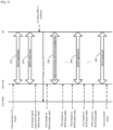
- FIG. 2 illustrates example WUR mode operation related MAC procedures operated by a WUR STA (e.g., 130) and the AP 110 according to a first embodiment of the present disclosure.
- the STA operates in PS mode after it is associated with the AP 110 via an association procedure.
- the STA Prior to entering WUR mode, the STA shall initiate a WUR negotiation procedure 210 with the AP 110 to negotiate wake-up operating parameters which govern WUR mode operation performed by the STA and the AP 110.
- the example wake-up operating parameters include
- the STA sends a WUR Mode Request frame to the AP 110 which contains requested wake-up operating parameters, and then the AP 110 responds with a WUR Mode Response frame which contains agreed wake-up operating parameters.
- the STA may initiate a WUR mode entry procedure 220 with the AP 110 for entering WUR mode.
- the STA transmits a WUR Mode Request frame to the AP 110 with a request for entering WUR mode, and then the AP 110 responds with a WUR Mode Response frame which indicates whether the STA's request for entering WUR mode is accepted or rejected.
- the STA After receiving the WUR Mode Response frame indicating the request for entering WUR mode is accepted, the STA enters WUR mode and stays in WUR doze state.
- the WUR of the STA in WUR doze state receives a unicast wake-up frame 202 from the AP 110, it transits to WUR awake state as shown in Figure 2 , and then initiates a DL data transmission and acknowledgement procedure 230 with the AP 110.
- the DL data transmission and acknowledgement procedure 230 it may transmit a PS-Poll frame to the AP 110 via its PCR to retrieve buffered traffic and acknowledge successful receipt of the wake-up frame 202.
- the AP 110 responds to the PS-Poll frame with a buffered Data frame or an ACK frame followed in a separate TXOP (Transmission Opportunity) by a buffered Data frame at the head of transmit queue.
- TXOP Transmission Opportunity
- the More Data field in the delivered Data frame is set to 1. Otherwise, the More Data field in the delivered Data frame is set to 0.
- the STA responds with an acknowledgement frame for acknowledging successful receipt of the Data frame.
- the acknoweldgement frame is either an ACK frame or a BlockAck frame. After transmitting the acknowledgement frame which acknowledges successful receipt of the Data frame with the More Data field set to 0, the STA transits to WUR doze state.
- the STA may transit to WUR awake state from WUR doze state even if no wake-up frame is received or no UL data traffic is buffered.
- new wake-up operating parameters e.g., duty cycle schedule of its WUR receiver
- the STA when it intends to negotiate new wake-up operating parameters (e.g., duty cycle schedule of its WUR receiver) with the AP 110, it transits to WUR awake state from WUR doze state and initiates another WUR negotiation procedure 240 with the AP 110.
- the STA sends a WUR Mode Request frame to the AP 110 which contains requested wake-up operating parameters, and then the AP 110 responds with a WUR Mode Response frame which contains agreed wake-up operating parameters and indicates when the agreed wake-up operating parameters will take effect.
- the STA After completing new wake-up operating parameter negotiation, the STA transits to WUR doze state. For another example, when the STA intends to exit WUR mode, it transits to WUR awake state from WUR doze state and initiates a WUR mode exit procedure 250 with the AP 110.
- the STA sends a WUR Mode Request frame to the AP 110 with a request for exiting WUR mode, and then the AP 110 responds with a WUR Mode Response frame which indicates whether the STA's request for exiting WUR mode is accepted or rejected.
- the STA After receiving the WUR Mode Response frame indicating the request for exiting WUR mode is accepted, the STA exits WUR mode and operates in PS mode only.
- the STA operating in WUR mode is allowed to initiate a WUR negotiation procedure with the AP 110 to negotiate new wake-up operating parameters as illustrated in Figure 2 , with no need of exiting WUR mode.
- channel efficiency is maximized.
- the AP 110 if the AP 110 intends to negotiate new wake-up operating parameters with the STA operating in WUR mode (e.g., WUR channel), it sends a wake-up frame to inform the STA operating in WUR mode that it intends to negotiate new wake-up operating parameters, as illustrated in Figure 10 . After receiving such a wake-up frame, the STA operating in WUR mode initiates a WUR negotiation procedure with the AP 110 to negotiate new wake-up operating parameters, with no need of exiting WUR mode. As a result, channel efficiency is maximized.
- WUR mode e.g., WUR channel
- one of wake-up operating parameters which can be negotiated during WUR negotiation is so called WUR sleep interval.
- the WUR sleep interval indicates to the AP 110 how often the STA operating in WUR mode turns on its PCR to receive Beacon frames for the purpose of keeping synchronized with the AP 110.
- the WUR sleep interval can be much larger than the WNM (Wireless Network Management) sleep interval defined in the IEEE Std 802.11 TM -2016 since unlike the STA operating in WNM sleep mode, the STA operating in WUR mode need not to wake to receive Beacon frames to check if there is buffered data traffic.
- WNM Wireless Network Management
- the AP 110 may request the STA to report recommended data rate based on the quality of received wake-up measurement signal transmitted in a WUR channel. As a result, the AP 110 can make an informed decision on the data rate which is used to transmit wake-up signal to the STA in the WUR channel.
- FIG. 3 illustrates example WUR mode operation related MAC procedures operated by a WUR STA and the AP 110 according to a second embodiment of the present disclosure.
- the STA operates in PS mode after it is associated with the AP 110 via an association procedure.
- the STA shall initiate an integrated WUR negotiation and WUR mode entry procedure 310 with the AP 110 for negotiating wake-up operating parameters and requesting to enter WUR mode.
- the STA sends a WUR Mode Request frame to the AP 110 which contains requested wake-up operating parameters and a request for entering WUR mode, and then the AP 110 responds with a WUR Mode Response frame which contains agreed wake-up operating parameters and indicates whether the STA's request for entering WUR mode is accepted or rejected.
- the STA After receiving the WUR Mode Response frame indicating the request for entering WUR mode is accepted, the STA enters WUR mode and stays in WUR doze state.
- the integrated WUR negotiation and WUR mode entry procedure 310 implements the same functionality as the WUR negotiation procedure 210 and the WUR mode entry procedure 220. As a result, the second embodiment has better channel efficiency than the first embodiment.
- the WUR receiver of the STA in WUR doze state when the WUR receiver of the STA in WUR doze state receives a unicast wake-up frame 302 from the AP 110, it changes its power management mode to active mode as shown in Figure 3 , and then initiate a DL data transmission and acknowledgement procedure 320 with the AP 110.
- the DL data transmission and acknowledgement procedure 320 it may transmit a QoS Null frame with the Power Management subfield set to 0 to the AP 110 via its PCR to retrieve buffered traffic and acknowledge successful receipt of the wake-up frame 302.
- the AP 110 responds to the QoS Null frame with an ACK frame, followed by a buffered Data frame at the head of transmit queue.
- the More Data field in the delivered Data frame is set to 1. Otherwise, the More Data field in the delivered Data frame is set to 0.
- the STA responds with an acknowledgement frame for acknowledging successful receipt of the Data frame.
- the acknoweldgement frame is either an ACK frame or a BlockAck frame.
- the STA may initiate a power management mode change procedure 330 for changing back to PS mode.
- the STA sends a QoS Null frame with the Power Management subfield set to 1 to the AP 110, and then the AP 110 responds with an ACK frame.
- the STA transits to operate in PS mode and stays in WUR doze state.
- the STA may transit to WUR awake state from WUR doze state even if no wake-up frame is received or no UL data traffic is buffered.
- new wake-up operating parameters e.g., duty cycle schedule of its WUR receiver
- the STA when it intends to negotiate new wake-up operating parameters (e.g., duty cycle schedule of its WUR receiver) with the AP 110, it transits to WUR awake state from WUR doze state and initiates another WUR negotiation procedure 340 with the AP 110.
- the STA sends a WUR Mode Request frame to the AP 110 which contains requested wake-up operating parameters, and then the AP 110 responds with a WUR Mode Response frame which contains agreed wake-up operating parameters and indicates when the agreed wake-up operating parameters will take effect.
- the STA After completing new wake-up operating parameter negotiation, the STA transits to WUR doze state. For another example, when the STA intends to exit WUR mode, it transits to WUR awake state from WUR doze state and initiates a WUR mode exit procedure 350 with the AP 110.
- the STA sends a WUR Mode Request frame to the AP 110 with a request for exiting WUR mode, and then the AP 110 responds with a WUR Mode Response frame which indicates whether the STA's request for exiting WUR mode is accepted or rejected.
- the STA After receiving the WUR Mode Response frame indicating the request for exiting WUR mode is accepted, the STA exits WUR mode and operates in PS mode only.
- the STA operating in WUR mode is allowed to initiate a WUR negotiation procedure with the AP 110 to negotiate new wake-up operating parameters as illustrated in Figure 3 , with no need of exiting WUR mode.
- channel efficiency is maximized.
- the AP 110 if the AP 110 intends to negotiate new wake-up operating parameters with the STA operating in WUR mode, it sends a wake-up frame to inform the STA operating in WUR mode that it intends to negotiate new wake-up operating parameters, as illustrated in Figure 10 . After receiving such a wake-up frame, the STA operating in WUR mode initiates a WUR negotiation procedure with the AP 110 to negotiate new wake-up operating parameters, with no need of exiting WUR mode. As a result, channel efficiency is maximized.
- all wake-up operating parameters can be carried in a WUR Mode element, as illustrated in Figure 12 .
- the WUR Mode element can be included in a WUR Action frame as illustrated in Figure 11 , e.g., WUR Mode Request frame or WUR Mode Response frame.
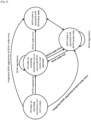
- Figure 4 illustrates WUR mode operation related state transition for the STA according to the first aspect of the present disclosure.
- the STA may have four states related to WUR mode operation. In a first state, all wake-up operating parameters are not in place. In a second state, all wake-up operating parameters are in place but WUR mode is not operated. In a third state, WUR mode is operated with WUR doze state. In a fourth state, WUR mode is operated with WUR awake state.
- the STA staying in the first state can transit to the second state after a WUR negotiation procedure is completed, transit to the third state after an integrated WUR negotiation and WUR mode entry procedure is completed and if the STA also operates in PS mode, or transit to the fourth state after an integrated WUR negotiation and WUR mode entry procedure is completed and if the STA also operates in active mode.
- the STA staying in the second state can transit to the third state after a WUR mode entry procedure is completed and if the STA also operates in PS mode, transit to the fourth state after a WUR mode entry procedure is completed and if the STA also operates in active mode, or update wake-up operating parameters after a WUR negotiation procedure is completed.
- the STA staying in the third state can transit to the fourth state for various reasons, e.g., when UL data traffic is buffered, or when a wake-up frame is received.
- the STA staying in the fourth state can transit to the second state after a WUR mode exit procedure is completed, or update wake-up operating parameters after a WUR negotiation procedure is completed.
- the STA staying in the fourth state can transit to the third state for various reasons, e.g., after transmitting an acknowledgement frame for acknowledging a DL Data frame with the More Data field set to 0, or receiving an acknowledgement frame which acknowledges an UL Data frame with the More Data field set to 0.
- wake-up operating parameters are classified into two categories: common wake-up operating parameters and user-specific wake-up operating parameters.
- the common wake-up operating parameters are applicable to all WUR STAs in the wireless network 100.
- the user-specific wake-up operating parameter are only applicable to a particular WUR STA in the wireless network 100.
- Example common wake-up operating parameters include
- Example user-specific wake-up operating parameters include
- common wake-up operating parameters can be carried in a WUR Operation element, as illustrated in Figure 15 .
- the WUR Operation element can be included in a Beacon frame, an Association Response frame, an Reassociation Response frame or a Probe Response frame.
- the formats of the Beacon frame, the Association Response frame, the Reassociation Response frame and the Probe Response frame are defined in the IEEE Std 802.11 TM -2016.
- user-specific wake-up operating parameters can be carried in a WUR Mode element, as illustrated in Figure 14 .
- the WUR Mode element can be included in a WUR Action frame as illustrated in Figure 11 (e.g., WUR Mode Request frame or WUR Mode Response frame), an Association Response frame or a Reassociation Response frame.
- common wake-up operating parameters can be obtained by the STA from the AP 110 via a synchronization procedure and/or an association procedure.
- User-specific wake-up operating parameters are negotiated between the STA and the AP 110 via a WUR negotiation procedure, an integrated WUR negotiation and WUR mode entry procedure, or an association procedure incorporating WUR negotiation. Since common wake-up operating parameters do not change as frequently as user-specific wake-up operating parameters, channel efficiency is maximized.
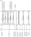
- FIG. 5 illustrates example WUR mode operation related MAC procedures operated by a WUR STA and the AP 110 according to a third embodiment of the present disclosure.
- the STA Before the STA is associated with the AP 110, it shall operate in active mode and initiate a synchronization procedure 510 to acquire synchronization with the AP 110 via passive scanning or active scanning.
- the STA if active scanning is performed, the STA sends a Probe Request frame to the AP 110, which may contain WUR capability information of the STA (e.g., time required for turning on its PCR and support of data rate feedback).
- the AP 110 responds with a Probe Response frame which contains common wake-up operating parameters as well as necessary synchronization information (e.g., TSF (Time Synchronization Function) timer).
- the Probe Response frame may contain WUR capability information of the AP 110 (e.g., support of frequency domain multiplexing transmission for multiple wake-up frames).
- the STA receives a Beacon frame from the AP 110 which contain common wake-up operating parameters as well as necessary synchronization information.
- the Beacon frame may contain WUR capability information of the AP 110.
- the STA After the STA gets synchronized with the AP 110 via the synchronization procedure 520, it may initiate an association procedure 520 with the AP 110. During the association procedure 520, the STA sends an Association Request frame or a Reassociation Request frame to the AP 110, which may contain WUR capability information of the STA. And then the AP 110 responds with an Association Response frame or a Reassociation Response frame which may contain common wake-up operating parameters and WUR capability information of the AP 110.
- the STA may initiate a power management mode change procedure 525 for changing its power management mode to PS mode after it is associated with the AP 110 via the association procedure 520 with the AP 110.
- the STA may transmit a QoS Null frame with the Power Management subfield set to 1 to the AP 110; and the AP 110 will respond with an ACK frame.
- the STA transits to operate in PS mode.
- the STA may initiate a WUR negotiation procedure 530 with the AP 110 to negotiate user-specific wake-up operating parameters.
- the STA sends a WUR Mode Request frame to the AP 110 which contains requested user-specific wake-up operating parameters, and then the AP 110 responds with a WUR Mode Response frame which contains agreed user-specific wake-up operating parameters.
- the STA may initiate a WUR mode entry procedure 540 with the AP 110.
- the STA transmit a WUR Mode Request frame to the AP 110 with a request for entering WUR mode, and then the AP 110 responds with a WUR Mode Response frame which indicates whether the STA's request for entering WUR mode is accepted or rejected.
- the STA enters WUR mode and stays in WUR doze state.
- the WUR of the STA staying in WUR doze state receives a unicast wake-up frame 502 from the AP 110, it transits to WUR awake state as shown in Figure 5 , and then initiates a DL data transmission and acknowledgement procedure 550 with the AP 110.
- the DL data transmission and acknowledgement procedure 550 it may transmit a PS-Poll frame to the AP 110 via its PCR to retrieve buffered traffic and acknowledge successful receipt of the wake-up frame 502.
- the AP 110 responds to the PS-Poll frame with a buffered Data frame or an ACK frame followed in a separate TXOP by a buffered Data frame at the head of transmit queue.
- the More Data field in the delivered Data frame is set to 1. Otherwise, the More Data field in the delivered Data frame is set to 0.
- the STA responds with an acknowledgement frame for acknowledging successful receipt of the Data frame.
- the acknoweldgement frame is either an ACK frame or a BlockAck frame. After transmitting the acknowledgement frame which acknowledges successful receipt of the Data frame with the More Data field set to 0, the STA transits to WUR doze state.
- the STA may transit to WUR awake state from WUR doze state even if no wake-up frame is received or no UL data traffic is buffered. For one example, when the STA intends to negotiate new user-specific wake-up operating parameters (e.g., duty cycle schedule of its WUR receiver) with the AP 110, it transits to WUR awake state from WUR doze state and initiates another WUR negotiation procedure 560 with the AP 110.
- new user-specific wake-up operating parameters e.g., duty cycle schedule of its WUR receiver
- the STA sends a WUR Mode Request frame to the AP 110 which contains requested user-specific wake-up operating parameters, and then the AP 110 responds with a WUR Mode Response frame which contains agreed user-specific wake-up operating parameters and indicates when the agreed wake-up operating parameters will take effect.
- the STA transits to WUR doze state. For another example, when the STA intends to exit WUR mode, it transits to WUR awake state from WUR doze state and initiates a WUR mode exit procedure 570 with the AP 110.
- the STA sends a WUR Mode Request frame to the AP 110 with a request for exiting WUR mode, and then the AP 110 responds with a WUR Mode Response frame which indicates whether the STA's request for exiting WUR mode is accepted or rejected. After receiving the WUR Mode Response frame indicating the request for exiting WUR mode is accepted, the STA exits WUR mode and operates in PS mode only.
- the STA operating in WUR mode is allowed to initiate a WUR negotiation procedure with the AP 110 to negotiate new user-specific wake-up operating parameters as illustrated in Figure 5 , with no need of exiting WUR mode.
- channel efficiency is maximized.
- the AP 110 if the AP 110 intends to negotiate new user-specific wake-up operating parameters with the STA operating in WUR mode, it sends a wake-up frame to inform the STA operating in WUR mode that it intends to negotiate new user-specific wake-up operating parameters, as illutrated in Figure 10 . After receiving such a wake-up frame, the STA operating in WUR mode initiates a WUR negotiation procedure with the AP 110 to negotiate new user-specific wake-up operating parameters, with no need of exiting WUR mode. As a result, channel efficiency is maximized.
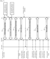
- FIG. 6 illustrates example WUR mode operation related MAC procedures operated by a WUR STA and the AP 110 according to a fourth embodiment of the present disclosure.
- the STA Before the STA is associated with the AP 110, it shall operate in active mode and initiate a synchronization procedure 610 to acquire synchronization with the AP 110 via passive scanning or active scanning.
- the STA sends a Probe Request frame to the AP 110 which may contain WUR capability information of the STA. And then the AP 110 responds with a Probe Response frame which contains common wake-up operating parameters as well as necessary synchronization information.
- the Probe Response frame may contain WUR capability information of the AP 110.
- the STA receives a Beacon frame from the AP 110 which contain common wake-up operating parameters as well as necessary synchronization information.
- the Beacon frame may contain WUR capability information of the AP 110.
- the STA After the STA gets synchronized with the AP 110 via the synchronization procedure 620, it may initiate an association procedure 620 with the AP 110. During the association procedure 620, the STA sends an Association Request frame or a Reassociation Request frame to the AP 110, which may contain WUR capability information of the STA. And then the AP 110 responds with an Association Response frame or a Reassociation Response frame which may contain common wake-up operating parameters and WUR capability information of the AP 110.
- the STA may initiate a power management mode change procedure 625 for changing its power management mode to PS mode after it is associated with the AP 110 via the association procedure 620 with the AP 110.
- the STA may transmit a QoS Null frame with the Power Management subfield set to 1 to the AP 110; and the AP 110 will respond with an ACK frame.
- the STA transits to operate in PS mode.
- the STA may initiate an integrated WUR negotiation and WUR mode entry procedure 630 with the AP 110 for negotiating user-specific wake-up operating parameters and requesting to enter WUR mode.
- the STA sends a WUR Mode Request frame to the AP 110 which contains requested user-specific wake-up operating parameters and a request for entering WUR mode, and then the AP 110 responds with a WUR Mode Response frame which contains agreed user-specific wake-up operating parameters and indicates whether the STA's request for entering WUR mode is accepted or rejected.
- the STA After receiving the WUR Mode Response frame indicating the request for entering WUR mode is accepted, the STA enters WUR mode and stays in WUR doze state.
- the integrated WUR negotiation and WUR mode entry procedure 630 implements the same functionality as the WUR negotiation procedure 530 and the WUR mode entry procedure 540 in the third embodiment. As a result, the fourth embodiment has better channel efficiency than the third embodiment.
- the WUR receiver of the STA staying in WUR doze state when the WUR receiver of the STA staying in WUR doze state receives a unicast wake-up frame 602 from the AP 110, it may change its power management mode to active mode from PS mode as shown in Figure 6 , and then initiate a DL data transmission and acknowledgement procedure 640 with the AP 110.
- the DL data transmission and acknowledgement procedure 640 it may transmit a QoS Null frame with the Power Management subfield set to 0 to the AP 110 via its PCR to retrieve buffered traffic and acknowledge successful receipt of the wake-up frame 602.
- the AP 110 responds to the QoS Null frame with an ACK frame, followed by a buffered Data frame at the head of transmit queue.
- the More Data field in the delivered Data frame is set to 1. Otherwise, the More Data field in the delivered Data frame is set to 0.
- the STA responds with an acknowledgement frame for acknowledging successful receipt of the Data frame.
- the acknoweldgement frame is either an ACK frame or a BlockAck frame.
- the STA may initiate a power management mode change procedure 650 for changing back to PS mode.
- the STA sends a QoS Null frame with the Power Management subfield set to 1 to the AP 110, and then the AP 110 responds with an ACK frame.
- the STA transits to operate in PS mode and stays in WUR doze state.
- the STA may transit to WUR awake state from WUR doze state even if no wake-up frame is received or no UL data traffic is buffered. For one example, when the STA intends to negotiate new user-specific wake-up operating parameters (e.g., duty cycle schedule of its WUR receiver) with the AP 110, it transits to WUR awake state from WUR doze state and initiates another WUR negotiation procedure 660 with the AP 110.
- new user-specific wake-up operating parameters e.g., duty cycle schedule of its WUR receiver
- the STA sends a WUR Mode Request frame to the AP 110 which contains requested user-specific wake-up operating parameters, and then the AP 110 responds with a WUR Mode Response frame which contains agreed user-specific wake-up operating parameters and indicates when the agreed user-specific wake-up operating parameters will take effect.
- the STA transits to WUR doze state. For another example, when the STA intends to exit WUR mode, it transits to WUR awake state from WUR doze state and initiates a WUR mode exit procedure 670 with the AP 110.
- the STA sends a WUR Mode Request frame to the AP 110 with a request for exiting WUR mode, and then the AP 110 responds with a WUR Mode Response frame which indicates whether the STA's request for exiting WUR mode is accepted or rejected. After receiving the WUR Mode Response frame indicating the request for exiting WUR mode is accepted, the STA exits WUR mode and operates in PS mode only.
- the STA operating in WUR mode is allowed to initiate a WUR negotiation procedure with the AP 110 to negotiate new user-specific wake-up operating parameters as illustrated in Figure 6 , with no need of exiting WUR mode.
- channel efficiency is maximized.
- the AP 110 if the AP 110 intends to negotiate new user-specific wake-up operating parameters with the STA operating in WUR mode, it sends a wake-up frame to inform the STA operating in WUR mode that it intends to negotiate new user-specific wake-up operating parameters, as illustrated in Figure 10 . After receiving such a wake-up frame, the STA operating in WUR mode initiates a WUR negotiation procedure with the AP 110 to negotiate new user-specific wake-up operating parameters, with no need of exiting WUR mode. As a result, channel efficiency is maximized.
- FIG. 7 illustrates example WUR mode operation related MAC procedures operated by a WUR STA and the AP 110 according to a fifth embodiment of the present disclosure.
- the STA Before the STA is associated with the AP 110, it shall operate in active mode and initiate a synchronization procedure 710 to acquire synchronization with the AP 110 via passive scanning or active scanning.
- the STA sends a Probe Request frame to the AP 110, which contains WUR capability information of the STA. And then the AP 110 responds with a Probe Response frame which contains common wake-up operating parameters as well as necessary synchronization information.
- the Probe Response frame also contains WUR capability information of the AP 110.
- the STA receives a Beacon frame from the AP 110 which contain common wake-up operating parameters as well as necessary synchronization information.
- the Beacon frame also contains WUR capability information of the AP 110.
- the STA may initiate an association procedure 720 with the AP 110, which incorporates WUR negotiation.
- the STA sends an Association Request frame or a Reassociation Request frame to the AP 110, which contains requested user-specific wake-up operating parameters.
- the AP 110 responds with an Association Response frame or a Reassociation Response frame, which contains agreed user-specific wake-up operating parameters.
- the association procedure 720 implements the same functionality as the association procedure 520 and the WUR negotiation procedure 530 in the third embodiment. As a result, the fifth embodiment has better channel efficiency than the third embodiment.
- the STA may initiate a power management mode change procedure 725 for changing its power management mode to PS mode after it is associated with the AP 110 via the association procedure 720 with the AP 110.
- the STA may transmit a QoS Null frame with the Power Management subfield set to 1 to the AP 110; and the AP 110 will respond with an ACK frame.
- the STA transits to operate in PS mode.
- the STA may initiate a WUR mode entry procedure 730 with the AP 110.
- the STA transmit a WUR Mode Request frame to the AP 110 with a request for entering WUR mode, and then the AP 110 responds with a WUR Mode Response frame which indicates whether the STA's request for entering WUR mode is accepted or rejected. After receiving the WUR Mode Response frame indicating the request for entering WUR mode is accepted, the STA enters WUR mode and stays in WUR doze state.
- the WUR of the STA staying in WUR doze state receives a unicast wake-up frame 702 from the AP 110, it transits to WUR awake state as shown in Figure 7 , and then initiates a DL data transmission and acknowledgement procedure 740 with the AP 110.
- the DL data transmission and acknowledgement procedure 740 it may transmit a PS-Poll frame to the AP 110 via its PCR to retrieve buffered traffic and acknowledge successful receipt of the wake-up frame 702.
- the AP 110 responds to the PS-Poll frame with a buffered Data frame or an ACK frame followed in a separate TXOP by a buffered Data frame at the head of transmit queue.
- the More Data field in the delivered Data frame is set to 1. Otherwise, the More Data field in the delivered Data frame is set to 0.
- the STA responds with an acknowledgement frame for acknowledging successful receipt of the Data frame.
- the acknoweldgement frame is either an ACK frame or a BlockAck frame. After transmitting the acknowledgement frame which acknowledges successful receipt of the Data frame with the More Data field set to 0, the STA transits to WUR doze state.
- the STA may transit to WUR awake state from WUR doze state even if no wake-up frame is received or no UL data traffic is buffered.
- the STA intends to negotiate new user-specific wake-up operating parameters (e.g., duty cycle schedule of its WUR receiver) with the AP 110
- it transits to WUR awake state from WUR doze state and initiates a WUR negotiation procedure 750 with the AP 110.
- the STA sends a WUR Mode Request frame to the AP 110 which contains requested user-specific wake-up operating parameters, and then the AP 110 responds with a WUR Mode Response frame which contains agreed user-specific wake-up operating parameters.
- the STA After receiving the WUR Mode Response frame, the STA transits to WUR doze state. For another example, when the STA intends to exit WUR mode, it transits to WUR awake state from WUR doze state and initiates a WUR mode exit procedure 760 with the AP 110. During the WUR mode exit procedure 760, the STA sends a WUR Mode Request frame to the AP 110 with a request for exiting WUR mode, and then the AP 110 responds with a WUR Mode Response frame which indicates whether the STA's request for exiting WUR mode is accepted or rejected. After receiving the WUR Mode Response frame indicating the request for exiting WUR mode is accepted, the STA exits WUR mode and operates in PS mode only.
- the STA operating in WUR mode is allowed to initiate a WUR negotiation procedure with the AP 110 to negotiate new user-specific wake-up operating parameters as illustrated in Figure 7 , with no need of exiting WUR mode.
- channel efficiency is maximized.
- the AP 110 if the AP 110 intends to negotiate new user-specific wake-up operating parameters with the STA operating in WUR mode, it sends a wake-up frame to inform the STA operating in WUR mode that it intends to negotiate new user-specific wake-up operating parameters, as illustrated in Figrue 10. After receiving such a wake-up frame, the STA operating in WUR mode initiates a WUR negotiation procedure with the AP 110 to negotiate new user-specific wake-up operating parameters, with no need of exiting WUR mode. As a result, channel efficiency is maximized.
- FIG. 8 illustrates example WUR mode operation related MAC procedures operated by a WUR STA and the AP 110 according to a sixth embodiment of the present disclosure.
- the STA Before the STA is associated with the AP 110, it shall operate in active mode and initiate a synchronization procedure 810 to acquire synchronization with the AP 110 via passive scanning or active scanning.
- the STA sends a Probe Request frame to the AP 110, which contains WUR capability information of the STA. And then the AP 110 responds with a Probe Response frame which contains common wake-up operating parameters as well as necessary synchronization information.
- the Probe Response frame also contains WUR capability information of the AP 110.
- the STA receives a Beacon frame from the AP 110 which contain common wake-up operating parameters as well as necessary synchronization information.
- the Beacon frame also contains WUR capability information of the AP 110.
- the STA After the STA gets synchronized with the AP 110 via the synchronization procedure 810, it may initiate an association procedure 820 with the AP 110, which incorporates WUR negotiation and WUR mode entry.
- the STA sends an Association Request or a Reassociation Request frame to the AP 110, which contains requested user-specific wake-up operating parameters and a request for entering WUR mode.
- the AP 110 responds with an Association Response frame or a Reassociation Response frame, which indicates whether the STA's request for entering WUR mode is accepted or rejected and contains agreed user-specific wake-up operating parameters.
- the STA After receiving the Association Response frame or the Reassociation Response frame indicating the request for entering WUR mode is accepted, the STA enters WUR mode and stays in WUR awake state.
- the association procedure 820 implements the same functionality as the association procedure 620 and the integrated WUR negotiation and WUR mode entry procedure 630 in the fourth embodiment. As a result, the sixth embodiment has better channel efficiency than the fourth embodiment.
- the STA may initiate a power management mode change procedure 825 for changing its power management mode to PS mode after it is associated with the AP 110 via the association procedure 820 with the AP 110.
- the STA may transmit a QoS Null frame with the Power Management subfield set to 1 to the AP 110; and the AP 110 will respond with an ACK frame.
- the STA transits to operate in PS mode and stays in WUR doze state.
- the WUR receiver of the STA staying in WUR doze state when the WUR receiver of the STA staying in WUR doze state receives a unicast wake-up frame 802 from the AP 110, it may change its power management mode to active mode as shown in Figure 8 , and then initiate a DL data transmission and acknowledgement procedure 830 with the AP 110.
- the DL data transmission and acknowledgement procedure 830 it may transmit a QoS Null frame with the Power Management subfield set to 0 to the AP 110 via its PCR to retrieve buffered traffic and acknowledge successful receipt of the wake-up frame 802.
- the AP 110 responds to the QoS Null frame with an ACK frame, followed by a buffered Data frame at the head of transmit queue.
- the More Data field in the delivered Data frame is set to 1. Otherwise, the More Data field in the delivered Data frame is set to 0.
- the STA responds with an acknowledgement frame for acknowledging successful receipt of the Data frame.
- the acknoweldgement frame is either an ACK frame or a BlockAck frame.
- the STA may initiate a power management mode change procedure 840 for changing back to PS mode.
- the STA sends a QoS Null frame with the Power Management subfield set to 1 to the AP 110, and then the AP 110 responds with an ACK frame.
- the STA transits to operate in PS mode and stays in WUR doze state.
- the STA may transit to WUR awake state from WUR doze state even if no wake-up frame is received or no UL data traffic is buffered.
- the STA intends to negotiate new user-specific wake-up operating parameters (e.g., duty cycle schedule of its WUR receiver) with the AP 110, it transits to WUR awake state from WUR doze state and initiates another WUR negotiation procedure 850 with the AP 110.
- the STA sends a WUR Mode Request frame to the AP 110 which contains requested user-specific wake-up operating parameters, and then the AP 110 responds with a WUR Mode Response frame which contains agreed user-specific wake-up operating parameters.
- the STA After receiving the WUR Mode Response frame, the STA transits to WUR doze state. For another example, when the STA intends to exit WUR mode, it transits to WUR awake state from WUR doze state and initiates a WUR mode exit procedure 860 with the AP 110. During the WUR mode exit procedure 860, the STA sends a WUR Mode Request frame to the AP 110 with a request for exiting WUR mode, and then the AP 110 responds with a WUR Mode Response frame which indicates whether the STA's request for exiting WUR mode is accepted or rejected. After receiving the WUR Mode Response frame indicating the request for exiting WUR mode is accepted, the STA exits WUR mode and operates in PS mode only.
- the STA operating in WUR mode is allowed to initiate a WUR negotiation procedure with the AP 110 to negotiate new user-specific wake-up operating parameters as illustrated in Figure 8 , with no need of exiting WUR mode.
- channel efficiency is maximized.
- the AP 110 if the AP 110 intends to negotiate new user-specific wake-up operating parameters with the STA operating in WUR mode, it sends a wake-up frame to inform the STA operating in WUR mode that it intends to negotiate new user-specific wake-up operating parameters, as illustrated in Figure 10 . After receiving such a wake-up frame, the STA operating in WUR mode initiates a WUR negotiation procedure with the AP 110 to negotiate new user-specific wake-up operating parameters, with no need of exiting WUR mode. As a result, channel efficiency is maximized.
- Figure 9 illustrates WUR mode operation related state transition for the STA according to the second aspect of the present disclosure.
- the STA has five states related to WUR mode operation. In a first state, all wake-up operating parameters are not in place. In a second state, common wake-up operating parameters are in place but user-specific wake-up operating parameters are not in place. In a third state, all wake-up operating parameters are in place but WUR mode is not operated. In a fourth state, WUR mode is operated with WUR doze state. In a fifth state, WUR mode is operated with WUR awake state.
- the STA staying in the first state can transit to the second state after a synchronization procedure and/or an association procedure is completed, transit to the third state after a synchronization procedure and an association procedure incorporating WUR negotiation is completed, transit to the fourth state after a synchronization procedure and an association procedure incoporating WUR negotiation and WUR mode entry is completed and if the STA also operates in PS mode, or transit to the fifth state after a synchronization procedure and an association procedure incoporating WUR negotiation and WUR mode entry is completed and if the STA also operates in active mode.
- the STA staying in the second state can transit to the third state after a WUR negotiation procedure is completed, transit to the fourth state after an integrated WUR negotiation and WUR mode entry procedure is completed and if the STA also operates in PS mode, or transit to the fifth state after an integrated WUR negotiation and WUR mode entry procedure is completed and if the STA also operates in active mode.
- the STA staying in the third state can transit to the fourth state after a WUR mode entry procedure is completed and if the STA also operates in PS mode, transit to the fifth state after a WUR mode entry procedure is completed and if the STA also operates in active mode, update user-specific wake-up operating parameters after a WUR negotiation procedure is completed, or update common wake-up operating parameters after a Beacon frame is received from the AP 110.
- the STA staying in the fourth state can transit to the fifth state for various reasons, e.g., when UL data traffic is buffered, or when a wake-up frame is received.
- the STA staying in the fifth state can transit to the third state after a WUR mode exit procedure is completed, update user-specific wake-up operating parameters after a WUR negotiation procedure is completed, or update common wake-up operating parameters after a Beacon frame is received from the AP 110.
- the STA staying in the fifth state can transit to the fourth state for various reasons, e.g., after acknowledging a DL Data frame with the More Data field set to 0 or receiving an acknowledgement frame which acknowledges an UL Data frame with the More Data field set to 0.
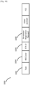
- FIG. 10 illustrates an example format of wake-up frame 1000 according to the present disclosure.
- the wake-up frame 1000 comprises a Type field 1002, a BSS Color field 1004, a STA ID field 1006, and a Parameter Negotiation Request field 1008.
- the Type field 1002 indicates the type of the wake-up frame 1000, e.g., unicast wake-up frame, multicast wake-up frame or WUR Beacon frame.
- the BSS Color field 1004 indicates the identifier of the network 100.
- the STA ID field 1006 indicates the identifier of intended STA. When the wake-up frame 1000 is not a unicast wake-up frame, the STA ID field 1006 is not present.
- the Parameter Negotiation Request field 1008 indicates whether the AP 110 intends to negotiate new wake-up operating parameters or new user-specific wake-up operating parameters.
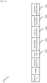
- FIG 11 illustrates an example format of WUR Action frame 1100 according to the present disclosure.
- the WUR Action frame 1100 comprises a MAC Header portion 1110 and a Frame Body portion 1120.
- the Frame Body portion 1120 comprises a WUR Action field 1122 and a WUR Mode element 1124.
- the WUR Action field 1122 indicates the type of the WUR Action frame 1100, e.g., WUR Mode Request frame or WUR Mode Response frame.
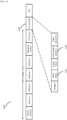
- FIG 12 illustrates an example format of WUR Mode element 1124 according to the first aspect of the present disclosure.
- the WUR Mode element 1124 comprises an Action Type field 1202, a WUR Mode Response Status field 1204, a Common Parameters field 1206, a User-Specific Parameters field 1208 and a Parameter Change Interval field 1210.
- the Action Type field 1202 indicates which one of the WUR negotiation procedure, the WUR mode entry procedure, the integrated WUR negotiation and WUR mode entry procedure and the WUR mode exit procedure the WUR Action frame 1120 containing the WUR Mode element 1124 involves, as illustrated in Figure 13 .
- the WUR Mode Response Status field 1204 indicates whether the request for entering or exiting WUR mode is accepted or rejected.
- the Common Parameters field 1206 contains common wake-up operating parameters such as the WUR Beacon interval, the WUR time unit and the minimum wake-up duration, etc.
- the User-Specific Parameters field 1208 contains user-specific wake-up operating parameters such as the WUR sleep interval, the duty cycle schedule of the STA's WUR receiver, the data rate feedback request, the WUR channel and the STA ID, etc.
- the Parameter Change Interval field 1210 indicates when new wake-up operating parameters take effect.
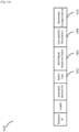
- FIG 14 illustrates an example format of WUR Mode element 1124 according to the second aspect of the present disclosure.
- the WUR Mode element 1124 comprises an Action Type field 1402, a WUR Mode Response Status field 1404, a User-Specific Parameters field 1408 and a Parameter Change Interval field 1410.
- the Action Type field 1402 indicates which one of the WUR negotiation procedure, the WUR mode entry procedure, the integrated WUR negotiation and WUR mode entry procedure and the WUR mode exit procedure the WUR Action frame 1120 containing the WUR Mode element 1124 involves, as illustrated in Figure 13 .
- the WUR Mode Response Status field 1404 indicates whether the request for entering or exiting WUR mode is accepted or rejected.
- the User-Specific Parameters field 1408 contains user-specific wake-up operating parameters such as the WUR sleep interval, the duty cycle schedule of the STA's WUR receiver, the data rate feedback request, the WUR channel and the STA ID, etc.
- the Parameter Change Interval field 1410 indicates when new user-specific wake-up operating parameters take effect.
- FIG. 15 illustrates an example format of WUR Operation element 1500 according to the second aspect of the present disclosure.
- the WUR Operation element 1500 comprises a Common Parameters field 1506.
- the Common Parameters field 1506 contains common wake-up operating parameters such as the WUR Beacon interval, the WUR time unit and the minimum wake-up duration, etc.
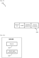
- FIG 16A is a simple block diagram of an example WUR 1600 which is capable of receiving wake-up signal.
- the WUR 1600 may be the WUR 134 in the STA 130 or the WUR 144 in the STA 140 as illustrated in Figure 1 .
- the WUR 1600 comprises a receiver 1610 and a receive signal processing circuitry 1620.
- the receiver 1610 is responsible for reception of wake-up signal
- the receive signal processing circuitry 1620 is responsible for processing the received wake-up signal.
- FIG 16B is a detailed block diagram of the example WUR 1600.
- the WUR 1600 further comprises control circuitry 1630, which is used to control general MAC protocol operations.
- the receiver 1610 of the WUR 1600 comprises PHY processing circuitry 1612, which is responsible for converting PPDUs received through antennas into MAC frames (e.g., wake-up frames or WUR Beacon frames).
- the receive signal processing circuitry 1620 of the WUR 1600 comprises a message processing circuitry 1622, which is responsible for processing the received MAC frames (e.g., parsing MAC Header, etc.) under the control of the control circuitry 1630 according to the various embodiments of the present disclosure and passing the corresponding MAC information to the control circuitry 1630.
- the WUR 1600 may comprise many other components that are not illustrated, for sake of clarity, in Figure 16A and Figure 16B . Only those components that are most pertinent to the present disclosure are illustrated.
- FIG 17A is a simple block diagram of an example PCR 1700 which is capable for transmitting and receiving standard IEEE 802.11 signal.
- the PCR 1700 may be the PCR 112 in the AP 110, the PCR 132 in the STA 130 or the PCR 142 in the STA 140 as illustrated in Figure 1 .
- the PCR 112 in the AP 110 is also capable for transmitting wake-up signal.
- the PCR 1700 comprises transmission signal generating circuitry 1710, a transceiver 1720 and receive signal processing circuitry 1730.
- the transmission signal generating circuitry 1710 is responsible for generating standard IEEE 802.11 signal and wake-up signal if applicable, the transceiver 1720 is responsible for transmitting the generated standard IEEE 802.11 signal and wake-up signal if applicable as well as receiving the standard IEEE 802.11 signal, and the receive signal processing circuitry 1730 is responsible for processing the received standard IEEE 802.11 signal.
- FIG 17B is a detailed block diagram of the example PCR 1700.
- the PCR 1700 further comprises control circuitry 1740, which is used to control general MAC protocol operation.
- the transmission signal generating circuitry 1710 comprises message generating circuitry 1712, which is responsible for generating MAC frames (e.g., Beacon frame, Probe Request/Response frame, Association Reqeust/Response frame, Reassociation Request/Response frame, Data frame, acknowledgement frame, WUR Action frame, wake-up frame and WUR Beacon frame) under the control of the control circuitry 1740 according to various embodiments of the present disclosure.
- MAC frames e.g., Beacon frame, Probe Request/Response frame, Association Reqeust/Response frame, Reassociation Request/Response frame, Data frame, acknowledgement frame, WUR Action frame, wake-up frame and WUR Beacon frame
- the transceiver 1720 comprises PHY processing circuitry 1722, which is responsible for formulating the generated MAC frames into PPDUs and transmitting them through antennas as well as converting PPDUs received through the antennas into MAC frames.
- the receive signal processing circuitry 1730 comprises message processing circuitry 1732, which is responsible for processing the received MAC frames (e.g., parsing MAC Header, etc.) under the control of the control circuitry 1740 and passing the corresponding MAC information to the control circuitry 1740.
- the PCR 1700 may comprise many other components that are not illustrated, for sake of clarity, in Figure 17A and Figure 17B . Only those components that are most pertinent to the present disclosure are illustrated.
- FIG 18 illustrates simplified WUR mode operation related state machine for the STA according to the present disclosure.
- the STA has three states related to WUR mode operation.
- the first state is called “no WUR” in which wake-up operating parameters are not in place.
- negotiating wake-up operating parameters between the AP 110 and the STA has not been completed or the negitiated wake-up operating parameters are discarded after the STA exits from the WUR mode.
- the first state as illustrated in Figure 18 corresponds to the first state as illustrated in Figure 4 or the first and second states as illustrated in Figure 9 .
- the second state is called "WUR Mode Suspend" in which wake-up operating parameters are in place but WUR mode is not operated.
- the second state as illustrated in Figure 18 corresponds to the second state as illustrated in Figure 4 or the third state as illustrated in Figure 9 .
- the third state is called "WUR Mode" in which the STA operates in the WUR mode according to the negotiated wake-up operating parameters.
- the third state as illustrated in Figure 18 corresponds to the third and fourth states as illustrated in Figure 4 or the fourth and fifth states as illustrated in Figure 9 .
- FIG 19A illustrates a first example two-way setup procedure according to the present disclsoure.
- the first example two-way setup procedure has the same functionality as the association procedure incorporating WUR negotiation as illustrated in Figure 7 .
- the STA transmits an Association Request frame or a Reassociation Request frame to the AP 110.
- the Association Request frame or the Reassociation Request frame contains a WUR Mode element (as illustrated in Figure 12 ) in which the Action Type field is set to "Enter WUR Mode Suspend Request" (as illustrated in Figure 25 ) and the User-Specific Parameters field contains the preferred duty cycle schedule of the STA's WUR receiver.
- the AP 110 responds with an Ack frame upon the successful receipt of the Association Request frame or the Reassociation Request frame. After that, the AP 110 transmits an Association Response frame or a Reassociation Response frame to the STA.
- the Association Response frame or the Reassociation Response frame contains a WUR Mode element (as illustrated in Figure 12 ) in which the Action Type field is set to "Enter WUR Mode Suspend Response" (as illustrated in Figure 25 ) and the WUR Mode Response Status field is set to "Enter WUR Mode Suspend Accept” or “Denied” (as illustrated in Figure 26 ). If the WUR Mode Response Status field is set to "Enter WUR Mode Suspend Accept", the Common Parameters field contains the WUR Beacon interval, etc and the User-Specific Parameters field contains the duty cycle schedule of the STA's WUR receiver, WID and WUR operating channel, etc.
- FIG 19B illustrates a second example two-way setup procedure according to the present disclosure.
- the second example two-way setup procedure has the same functionality as the WUR negotiation procedure as illustrated in Figure 2 .
- the STA transmits a WUR Mode Setup frame to the AP 110.
- the WUR Mode Setup frame is a WUR Action frame (as illustrated in Figure 11 ) with the WUR Action field set to "WUR Mode Setup" (as illustrated in Figure 24 ).
- the WUR Mode Setup frame contains a WUR Mode element (as illustrated in Figure 12 ) in which the Action Type field is set to "Enter WUR Mode Suspend Request" (as illustrated in Figure 25 ) and the User-Specific Parameters field contains the preferred duty cycle schedule of the STA's WUR receiver.
- the AP 110 responds with an Ack frame upon the successful receipt of the WUR Mode Setup frame. After that, the AP 110 transmits an WUR Mode Setup frame to the STA.
- the WUR Mode Setup frame contains a WUR Mode element (as illustrated in Figure 12 ) in which the Action Type field is set to "Enter WUR Mode Suspend Response" (as illustrated in Figure 25 ) and the WUR Mode Response Status field is set to "Enter WUR Mode Suspend Accept” or "Denied” (as illustrated in Figure 26 ). If the WUR Mode Response Status field is set to "Enter WUR Mode Suspend Accept", the Common Parameters field contains the WUR Beacon interval, etc and the User-Specific Parameters field contains the duty cycle schedule of the STA's WUR receiver, WID and WUR operating channel, etc. If the WUR Mode Response Status field is set to "Denied", the Common Parameters field and the User-Specific Parameters field are not present.
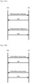
- FIG 20A illustrates a first example one-way teardown procedure initiated by the STA.
- the STA transmits a WUR Mode Teardown frame to the AP 110.
- the WUR Mode Teardown frame is a WUR Action frame (as illustrated in Figure 11 ) with the WUR Action field set to "WUR Mode Teardown" (as illustrated in Figure 24 ).
- the WUR Mode Teardown frame does not include a WUR Mode element.
- the AP 110 responds with an Ack frame upon the successful receipt of the WUR Mode Teardown frame.
- FIG. 20B illustrates a second example one-way teardown procedure initiated by the AP 110.
- the AP 110 transmits an WUR Mode Teardown frame to the STA.
- the WUR Mode Teardown frame does not include a WUR Mode element.
- the STA responds with an Ack frame upon the successful receipt of the WUR Mode Teardown frame. After transmitting the Ack frame, the STA discards the negotiated wake-up operating parameters.
- FIG 19A illustrates a first example two-way setup procedure.
- the first example two-way setup procedure has the same functionality as the association procedure incorporatig integrated WUR negotiation and WUR mode entry as illustrated in Figure 8 .
- the STA transmits an Association Request frame or a Reassociation Request frame to the AP 110.
- the Association Request frame or the Reassociation Request frame contains a WUR Mode element (as illustrated in Figure 12 ) in which the Action Type field is set to "Enter WUR Mode Request" (as illustrated in Figure 25 ) and the User-Specific Parameters field contains the preferred duty cycle schedule of the STA's WUR receiver.
- the AP 110 responds with an Ack frame upon the successful receipt of the Association Request frame or the Reassociation Request frame. After that, the AP 110 transmits an Association Response frame or a Reassociation Response frame to the STA.
- the Association Response frame or the Reassociation Response frame contains a WUR Mode element (as illustrated in Figure 12 ) in which the Action Type field is set to "Enter WUR Mode Response" (as illustrated in Figure 25 ) and the WUR Mode Response Status field is set to "Enter WUR Mode Accept” or "Denied” (as illustrated in Figure 26 ). If the WUR Mode Response Status field is "Enter WUR Mode Accept", the Common Parameters field contains the WUR Beacon interval, etc and the User-Specific Parameters field contains the duty cycle schedule of the STA's WUR receiver, WID and WUR operating channel, etc. If the WUR Mode Response Status field is set to "Denied", the Common Parameters field and the User-Specific Parameters field are not present.
- FIG 19B illustrates a second example two-way setup procedure.
- the second example two-way setup procedure has the same functionality as the integrated WUR negotiation and WUR mode entry procedure as illustrated in Figure 3 .
- the STA transmits an WUR Mode Setup frame to the AP 110.
- the WUR Mode Setup frame contains a WUR Mode element (as illustrated in Figure 12 ) in which the Action Type field is set to "Enter WUR Mode Request" (as illustrated in Figure 25 ) and the User-Specific Parameters field contains the preferred duty cycle schedule of the STA's WUR receiver.
- the AP 110 responds with an Ack frame upon the successful receipt of the WUR Mode Setup frame. After that, the AP 110 transmits an WUR Mode Setup frame to the STA.
- the WUR Mode Setup frame contains a WUR Mode element (as illustrated in Figure 12 ) in which the Action Type field is set to "Enter WUR Mode Response" (as illustrated in Figure 25 ) and the WUR Mode Response Status field is set to "Enter WUR Mode Accept” or "Denied” (as illustrated in Figure 26 ). If the WUR Mode Response Status field is "Enter WUR Mode Accept", the Common Parameters field contains the WUR Beacon interval, etc and the User-Specific Parameters field contains the duty cycle schedule of the STA's WUR receiver, WID and WUR operating channel, etc. If the WUR Mode Response Status field is set to "Denied”, the Common Parameters field and the User-Specific Parameters field are not present.
- FIG 20A illustrates a first example one-way teardown procedure initiated by the STA.
- the STA transmits a WUR Mode Teardown frame to the AP 110.
- the WUR Mode Teardown frame is a WUR Action frame (as illustrated in Figure 11 ) with the WUR Action field set to "WUR Mode Teardown" (as illustrated in Figure 24 ).
- the WUR Mode Teardown frame does not include a WUR Mode element.
- the AP 110 responds with an Ack frame upon the successful receipt of the WUR Mode Teardown frame.
- FIG. 20B illustrates a second example one-way teardown procedure initiated by the AP 110.
- the AP 110 transmits an WUR Mode Teardown frame to the STA.
- the WUR Mode Teardown frame does not include a WUR Mode element.
- the STA responds with an Ack frame upon the successful receipt of the WUR Mode Teardown frame. After transmitting the Ack frame, the STA exits from the WUR mode and discards the negotiated wake-up operating parameters.
- FIG 21A illustrates an example one-way setup procedure initiated by the STA.
- the example one-way setup procedure has the same functionality as the WUR mode entry procedure as illustrated in Figure 5 .
- the STA transmits a WUR Mode Setup frame to the AP 110.
- the WUR Mode Setup frame contains a WUR Mode element (as illustrated in Figure 12 ) in which the Action Type field is set to "Enter WUR Mode" (as illustrated in Figure 25 ) and the Common Parameters field and the User-Specific Parameters field are not present.
- the AP 110 responds with an Ack frame upon the successful receipt of the WUR Mode Setup frame. After receiving the Ack frame, the STA operates in the WUR mode according to the existing wake-up operating parameters.
- Figure 19B illustrates an example two-way setup procedure initiated by the STA.
- the example two-way setup procedure has the same functionality as the integrated WUR mode entry and WUR negotiation procedure as illustrated in Figure 3 .
- the STA transmits a WUR Mode Setup frame to the AP 110.
- the WUR Mode Setup frame contains a WUR Mode element (as illustrated in Figure 12 ) in which the Action Type field is set to "Enter WUR Mode Request" (as illustrated in Figure 25 ) and the User-Specific Parameters field contains the preferred duty cycle schedule of the STA's WUR receiver.
- the AP 110 responds with an Ack frame upon the successful receipt of the WUR Mode Setup frame. After that, the AP 110 transmits a WUR Mode Setup frame to the STA.
- the WUR Mode Setup frame contains a WUR Mode element (as illustrated in Figure 12 ) in which the Action Type field is set to "Enter WUR Mode Response" (as illustrated in Figure 25 ) and the WUR Mode Response Status field is set to "Enter WUR Mode Accept" or "Denied” (as illustrated in Figure 26 ).
- the WUR Mode Response Status field is "Enter WUR Mode Accept"
- the Common Parameters field contains the WUR Beacon interval, etc and the User-Specific Parameters field contains the duty cycle schedule of the STA's WUR receiver, WID and WUR operating channel, etc. If the WUR Mode Response Status field is set to "Denied”, the Common Parameters field and the User-Specific Parameters field are not present.
- FIG 21A illustrates a first example one-way setup procedure initiated by the STA.
- the first example one-way setup procedure has the same functionality as the WUR mode exit procedure as illustrated in Figure 2 .
- the STA transmits a WUR Mode Setup frame to the AP 110.
- the WUR Mode Setup frame contains a WUR Mode element (as illustrated in Figure 12 ) in which the Action Type field is set to "Enter WUR Mode Suspend" (as illustrated in Figure 25 ) and the Common Parameters field and the User-Specific Parameters field are not present.
- the AP 110 responds with an Ack frame upon the successful receipt of the WUR Mode Setup frame. After receiving the Ack frame, the STA exits from the WUR mode and maintains the negotiated wake-up operating parameters.
- Figure 21B illustrates a second example one-way setup procedure initiated by the AP 110.
- the AP 110 transmits a WUR Mode Setup frame to the STA.
- the WUR Mode Setup frame contains a WUR Mode element (as illustrated in Figure 12 ) in which the Action Type field is set to "Enter WUR Mode Suspend" (as illustrated in Figure 25 ) and the Common Parameters field and the User-Specific Parameters field are not present.
- the STA responds with an Ack frame upon the successful receipt of the WUR Mode Setup frame. After transmitting the Ack frame, the STA exits from the WUR mode and maintains the negotiated wake-up operating parameters.
- the wake-up operating parameters can be updated via a one-way procedure initiated by the AP 110 or a two-way update procedure initiated by the STA.
- Figure 22 illustrates an example one-way update procedure initiated by the AP 110.
- the AP 110 transmits a WUR Mode Update frame to the STA.
- the WUR Mode Update frame is a WUR Action frame (as illustrated in Figure 11 ) with the WUR Action field set to "WUR Mode Update" (as illustrated in Figure 24 ).
- the WUR Mode Update frame contains a WUR Mode element (as illustrated in Figure 12 ) in which the Action Type field is set to "Update WUR Parameters" (as illustrated in Figure 25 ), the Common Parameters field contains the WUR Beacon interval, etc., the User-Specific Parameters field contains the duty cycle schedule of the STA's WUR receiver, WID and WUR operating channel, etc., and the Parameter Change Interval field indicates when new wake-up operating parameters take effect.
- the STA responds with an Ack frame upon the successful receipt of the WUR Mode Update frame and updates the wake-up operating parameters accordingly.
- Figure 23 illustrates an example two-way update procedure initiated by the STA.
- the example two-way update procedure has the same functionality as the WUR negotiation procedure as illustrated in Figure 2 .
- the STA transmits a WUR Mode Update frame to the AP 110.
- the WUR Mode Update frame contains a WUR Mode element (as illustrated in Figure 12 ) in which the Action Type field is set to "Update WUR Parameters Request" (as illustrated in Figure 25 ) and the User-Specific Parameters field contains the preferred duty cycle schedule of the STA's WUR receiver.
- the AP 110 responds with an Ack frame upon the successful receipt of the WUR Mode Update frame. After that, the AP 110 transmits a WUR Mode Update frame to the STA.
- the WUR Mode Update frame contains a WUR Mode element (as illustrated in Figure 12 ) in which the Action Type field is set to "Update WUR Parameters Response" (as illustrated in Figure 25 ), the Common Parameters field contains the WUR Beacon interval, etc, the User-Specific Parameters field contains the duty cycle schedule of the STA's WUR receiver, WID and WUR operating channel, etc., and the Parameter Change Interval field indicates when new wake-up operating parameters take effect.
- the STA responds with an Ack frame upon the successful receipt of the WUR Mode Update frame and updates the wake-up operating parameters accordingly.
- the one-way update procedure as illustrated in Figure 22 is preferable since it results in less channel overhead than the two-way update procedure as illustrated in Figure 23 .
- the two-way setup procedure as illustrated in Figure 19B is preferable since it results in less channel overhead than the two-way update procedure as illustrated in Figure 23 followed by the one-way setup procedure as illustrated in Figure 21A .
- FIG 24 illustrates another example format of the WUR Action field 1122 of the WUR Action frame 1100 according to the present disclosure.
- the WUR Action field 1122 indicates the type of the WUR Action frame 1100, e.g., WUR Mode Setup frame, WUR Mode Teardown frame or WUR Mode Update frame.
- Figure 25 illustrates another example format of the Action Type field 1202 of the WUR Mode element 1124 according to the present disclosure.
- the Action Type field 1202 indicates the WUR mode operation related action for the Association Request frame, the Association Response frame, the Reassociation Request frame, the Reassociation Response frame, the WUR Mode Setup frame or the WUR Mode Update frame containing the WUR Mode element 1124.
- FIG 26 illustrates another example format of the WUR Mode Response Status 1204 of the WUR Mode element 1124 according to the present disclosure.
- the WUR Mode Response Status 1204 indicates the STA's request for operating in the "WUR Mode” or "WUR Mode Suspend” is accepted or rejected.
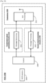
- FIG. 27 is a detailed block diagram of another example WUR 1600.
- the WUR 1600 further comprises control circuitry 2730 and a WUR memory 2740.
- the control circuitry 2730 is used to control general MAC protocol operations.
- the receiver 1610 comprises PHY processing circuitry 2712, which is responsible for converting PPDUs received through antennas into MAC frames (e.g., wake-up frames or WUR Beacon frames).
- the receive signal processing circuitry 1620 comprises message processing circuitry 2722, which is responsible for processing the received MAC frames under the control of the control circuitry 2730 according to the various embodiments of the present disclosure and passing the corresponding MAC information to the control circuitry 2730.
- the WUR memory 2740 is responsible for storing the negotiated wake-up operating parameters between the WUR STA (e.g., 130 or 140) containing the WUR 1600 and the AP 110, especially when the WUR STA operates in the "WUR Mode Suspend".
- FIG 28 is a detailed block diagram of another example PCR 1700.
- the PCR 1700 further comprises control circuitry 2840.
- the control circuitry 2840 is used to control general MAC protocol operation.
- the transmission signal generating circuitry 1710 comprises message generating circuitry 2812, which is responsible for generating MAC frames (e.g., Beacon frame, Probe Request/Response frame, Association Reqeust/Response frame, Reassociation Request/Response frame, Data frame, acknowledgement frame, WUR Action frame, wake-up frame and WUR Beacon frame) under the control of the control circuitry 2840 according to various embodiments of the present disclosure.
- MAC frames e.g., Beacon frame, Probe Request/Response frame, Association Reqeust/Response frame, Reassociation Request/Response frame, Data frame, acknowledgement frame, WUR Action frame, wake-up frame and WUR Beacon frame
- the transceiver 1720 comprises PHY processing circuitry 2822, which is responsible for formulating the generated MAC frames into PPDUs and transmitting them through antennas as well as converting PPDUs received through the antennas into MAC frames.
- the receive signal processing circuitry 1730 comprises message processing circuitry 2832, which is responsible for processing the received MAC frames (e.g., parsing MAC Header, etc.) under the control of the control circuitry 2840 and passing the corresponding MAC information to the control circuitry 2840.
- the PCR 1700 when used in the AP 110, it further comprises a WUR memory 2850, which is responsible for storing the negotiated wake-up operating parameters between the WUR STAs (e.g., 130 and 140) and the AP 110, especially when the WUR STAs operate in the "WUR Mode Suspend".
- a WUR memory 2850 which is responsible for storing the negotiated wake-up operating parameters between the WUR STAs (e.g., 130 and 140) and the AP 110, especially when the WUR STAs operate in the "WUR Mode Suspend".
- the present disclosure can be realized by software, hardware, or software in cooperation with hardware.
- Each functional block used in the description of each embodiment described above can be partly or entirely realized by an LSI such as an integrated circuit, and each process described in the each embodiment may be controlled partly or entirely by the same LSI or a combination of LSIs.
- the LSI may be individually formed as chips, or one chip may be formed so as to include a part or all of the functional blocks.
- the LSI may include a data input and output coupled thereto.
- the LSI here may be referred to as an IC, a system LSI, a super LSI, or an ultra LSI depending on a difference in the degree of integration.
- the technique of implementing an integrated circuit is not limited to the LSI and may be realized by using a dedicated circuit, a general-purpose processor, or a special-purpose processor.
- a FPGA Field Programmable Gate Array
- a reconfigurable processor in which the connections and the settings of circuit cells disposed inside the LSI can be reconfigured may be used.
- the present disclosure can be realized as digital processing or analogue processing, as a result of the advancement of semiconductor technology or other derivative technology.
- This disclosure can be applied to an apparatus and a method for WUR mode operation in a wireless network.
Landscapes
- Engineering & Computer Science (AREA)
- Computer Networks & Wireless Communication (AREA)
- Signal Processing (AREA)
- Mobile Radio Communication Systems (AREA)
Claims (8)
- Station (130, 140), die umfasst:eine Schaltung (1710; 1730), die im Betrieb dazu konfiguriert ist, WUR-Parameter (Wake-Up Radio) mit einem Zugangspunkt (Access Point, AP) (110), auszuhandeln und vom WUR-Suspend-Modus in den WUR-Modus umzuschalten, indem sie einen WUR-Modus-Setup-Rahmenaustausch initiiert und abschließt; undeinen Sender (1720), der im Betrieb dazu konfiguriert ist, einen WUR-Modus-Setup-Rahmen an den AP (110) im WUR-Modus-Setup-Rahmenaustausch zu senden,wobei die Schaltung (1720; 1730) dazu konfiguriert ist, die mit dem AP (110) ausgehandelten WUR-Parameter beizubehalten, nachdem sie aus dem WUR-Modus in den WUR-Suspend-Modus eingetreten ist,wobei die Schaltung (1710; 1730) dazu konfiguriert ist, nach der Aushandlung des WUR-Energieverwaltungsdienstes vom WUR-Suspend-Modus in den WUR-Modus umzuschalten,wobei ein Aktionstyp-Feld eines WUR-Modus-Elements, das in dem WUR-Modus-Setup-Rahmen enthalten ist, zum Anzeigen konfiguriert ist, dass die Station (130, 140) in den WUR-Modus eintritt,dadurch gekennzeichnet, dassdas WUR-Modus-Element verwendet wird, um einen ersten Satz von Parametern auszuhandeln, die sich auf den WUR-Betrieb beziehen, und die Station (130, 140) ferner einen Empfänger umfasst, der im Betrieb dazu konfiguriert ist, einen Bakenrahmen zu empfangen, der ein WUR-Betrieb-Element enthält, das einen zweiten Satz von Parametern enthält, die erforderlich sind, um den WUR-Betrieb zu unterstützen, wobei sich jeder der Parameter im ersten Satz von jedem der Parameter im zweiten Satz unterscheidet.
- Station (130, 140) nach Anspruch 1, wobei der Sender (1720) dazu konfiguriert ist, an den AP (110) einen Anforderungsrahmen zu senden, der eine Anforderung zum Eintritt in den WUR-Suspend-Modus anzeigt, und wenn ein Antwortrahmen von dem AP anzeigt, dass der AP die Anforderung akzeptiert, die Schaltung (1710; 1730) dazu konfiguriert ist, bei der Verhandlung in den WUR-Suspend-Modus einzutreten.
- Station (130, 140) nach Anspruch 2, wobei ein Aktionstyp-Feld eines WUR-Modus-Elements innerhalb des Anforderungsrahmens die Anforderung angibt.
- Station (130, 140) nach Anspruch 2, wobei ein Aktionstyp-Feld eines WUR-Modus-Elements innerhalb des Antwortrahmens anzeigt, dass der AP die Anforderung akzeptiert.
- Station (130, 140) nach einem der Ansprüche 1 bis 4, wobei die Schaltung (1710; 1730) dazu konfiguriert ist, den WUR-Energieverwaltungsdienst abzubauen, indem sie einen WUR-Modus-Abbaurahmen initiiert.
- Station (130, 140) nach Anspruch 1, wobei der erste Satz von Parametern den WUR-Kanal-Offset und die WUR-Tastverhältnis-Startzeit beinhaltet.
- Station (130, 140) nach Anspruch 1, wobei der zweite Satz von Parametern eine minimale Aufwachdauer, WUR-Kanalinformationen und eine WUR-Bakenperiode umfasst.
- Kommunikationsverfahren, das von einer Station (130, 140) implementiert wird, wobei das Kommunikationsverfahren umfasst:Aushandeln von WUR- Parametern (Wake-Up Radio) mit einem Zugangspunkt (Access Point, AP) (110);Umschalten vom WUR-Suspend-Modus in den WUR-Modus durch Initiieren und Abschließen eines WUR-Modus-Setup-Rahmenaustauschs; undSenden eines WUR-Modus-Setup-Rahmens an den AP (110) im WUR-Modus-Setup-Rahmenaustausch,wobeidie Station (130, 140) die mit dem AP (110) ausgehandelten WUR-Parameter beibehält, nachdem sie aus dem WUR-Modus in den WUR-Suspend-Modus eingetreten ist,das Kommunikationsverfahren ferner das Umschalten aus dem WUR-Suspend-Modus in den WUR-Modus nach der Aushandlung des WUR-Energieverwaltungsdienstes umfasst,wobei ein Aktionstyp-Feld eines WUR-Modus-Elements, das in dem WUR-Modus-Setup-Rahmen enthalten ist, anzeigt, dass die Station (130, 140) in den WUR-Modus eintritt,dadurch gekennzeichnet, dassdas WUR-Modus-Element verwendet wird, um einen ersten Satz von Parametern in Bezug auf den WUR-Betrieb auszuhandeln, unddas Kommunikationsverfahren ferner das Empfangen eines Bakenrahmens umfasst, der ein WUR-Betrieb-Element enthält, das einen zweiten Satz von Parametern enthält, die erforderlich sind, um den WUR-Betrieb zu unterstützen, wobei sich jeder der Parameter im ersten Satz von jedem der Parameter im zweiten Satz unterscheidet.
Applications Claiming Priority (3)
| Application Number | Priority Date | Filing Date | Title |
|---|---|---|---|
| JP2017165789 | 2017-08-30 | ||
| JP2017245247 | 2017-12-21 | ||
| PCT/JP2018/029535 WO2019044421A1 (en) | 2017-08-30 | 2018-08-07 | COMMUNICATION APPARATUS AND COMMUNICATION METHOD |
Publications (4)
| Publication Number | Publication Date |
|---|---|
| EP3677073A1 EP3677073A1 (de) | 2020-07-08 |
| EP3677073A4 EP3677073A4 (de) | 2020-09-30 |
| EP3677073B1 true EP3677073B1 (de) | 2024-11-06 |
| EP3677073C0 EP3677073C0 (de) | 2024-11-06 |
Family
ID=65524937
Family Applications (1)
| Application Number | Title | Priority Date | Filing Date |
|---|---|---|---|
| EP18852557.0A Active EP3677073B1 (de) | 2017-08-30 | 2018-08-07 | Kommunikationsvorrichtung und kommunikationsverfahren |
Country Status (6)
| Country | Link |
|---|---|
| US (1) | US11638213B2 (de) |
| EP (1) | EP3677073B1 (de) |
| JP (1) | JP7066757B2 (de) |
| CN (1) | CN111034281B (de) |
| TW (1) | TWI766081B (de) |
| WO (1) | WO2019044421A1 (de) |
Families Citing this family (13)
| Publication number | Priority date | Publication date | Assignee | Title |
|---|---|---|---|---|
| US10959174B2 (en) * | 2017-09-02 | 2021-03-23 | Apple Inc. | Wake-up radio with urgent-data criterion |
| US11647463B2 (en) * | 2017-09-13 | 2023-05-09 | Intel Corporation | Methods and arrangements to enable wake-up receiver for modes of operation |
| ES2965204T3 (es) * | 2017-09-22 | 2024-04-11 | Zte Corp | Exploración y asociación de nodos de comunicación inalámbrica |
| US11576123B2 (en) | 2017-10-11 | 2023-02-07 | Intel Corporation | Methods and arrangements to support wake-up radio packet transmission |
| WO2019125086A1 (ko) * | 2017-12-21 | 2019-06-27 | 주식회사 윌러스표준기술연구소 | 웨이크-업 라디오를 이용하는 무선 통신 방법 및 무선 통신 단말 |
| US11375453B2 (en) | 2017-12-21 | 2022-06-28 | Apple Inc. | Power-efficient communication of group-addressed frames |
| US11589309B2 (en) | 2018-01-12 | 2023-02-21 | Intel Corporation | Methods and arrangements to support wake-up radio packet transmission |
| JP7277109B2 (ja) * | 2018-11-08 | 2023-05-18 | キヤノン株式会社 | 通信装置、制御方法、及びプログラム |
| CN118199827A (zh) | 2020-04-14 | 2024-06-14 | 华为技术有限公司 | 一种通信方法和通信装置 |
| CN112188451A (zh) * | 2020-11-10 | 2021-01-05 | 北京百瑞互联技术有限公司 | 一种蓝牙mesh低功耗节点的休眠唤醒方法、装置及介质 |
| CN114615724B (zh) * | 2020-12-08 | 2024-10-25 | 瑞昱半导体股份有限公司 | 具有唤醒管理机制的蓝牙网状网络系统及其联机方法 |
| US11350458B1 (en) | 2020-12-10 | 2022-05-31 | Dell Products L.P. | System and method for dynamic sensitivity control for interference avoidance |
| US20250031148A1 (en) * | 2023-07-18 | 2025-01-23 | Samsung Electronics Co., Ltd. | Wake-up time recommendation by an access point |
Family Cites Families (21)
| Publication number | Priority date | Publication date | Assignee | Title |
|---|---|---|---|---|
| KR100665457B1 (ko) * | 2003-04-30 | 2007-01-04 | 삼성전자주식회사 | 광대역 무선 접속 통신 시스템에서 슬립 모드 및 어웨이크 모드에서의 상태 천이 제어 시스템 및 방법 |
| PL2052558T3 (pl) | 2006-08-18 | 2015-03-31 | Ericsson Telefon Ab L M | Redukowanie czasu przejścia stanu |
| KR20100052064A (ko) * | 2008-11-10 | 2010-05-19 | 삼성전자주식회사 | 이동 통신 시스템에서 불연속 수신 동작 제어 방법 및 장치 |
| CN102076067A (zh) * | 2010-12-23 | 2011-05-25 | 北京星网锐捷网络技术有限公司 | 无线站点的休眠方法、装置和设备及通信系统 |
| EP2732665B1 (de) * | 2011-07-14 | 2018-10-10 | LG Electronics Inc. | Verfahren zur kommunikation im energiesparmodus in einem wlan und vorrichtung dafür |
| CN104094665B (zh) * | 2012-02-02 | 2018-05-15 | Lg电子株式会社 | 在无线lan系统中接入信道的方法和设备 |
| EP2699040B1 (de) | 2012-08-06 | 2015-04-08 | Itron, Inc. | Multimedia-Mehrfachmodulation und Maschennetzwerk mit Mehrfachdatenraten |
| US9313739B2 (en) | 2012-10-23 | 2016-04-12 | Qualcomm Incorporated | Systems and methods for low power wake up signal and operations for WLAN |
| US9241307B2 (en) * | 2012-10-24 | 2016-01-19 | Qualcomm Incorporated | Method and apparatus using an ultra low power signal with scheduled power save modes |
| US9544848B2 (en) | 2012-10-24 | 2017-01-10 | Qualcomm Incorporated | Methods and apparatus for communicating short paging messages in a wireless communication network |
| WO2014098445A1 (ko) * | 2012-12-17 | 2014-06-26 | 엘지전자 주식회사 | 무선랜 시스템에서 채널 액세스 방법 및 장치 |
| US10028272B2 (en) * | 2013-02-24 | 2018-07-17 | Lg Electronics Inc. | Method and apparatus for exchanging frame for a low-power device in a wireless local area network (WLAN) system |
| WO2014165614A2 (en) * | 2013-04-03 | 2014-10-09 | Motorola Mobility Llc | Methods and devices for cell discovery |
| KR20170013251A (ko) * | 2014-06-02 | 2017-02-06 | 엘지전자 주식회사 | 무선랜에서 파워 세이브 모드 기반의 동작 방법 및 장치 |
| US9749955B2 (en) | 2015-07-20 | 2017-08-29 | Intel Corporation | Connectivity management for mobile wireless low-power wake-up radios |
| US10194394B2 (en) * | 2016-08-12 | 2019-01-29 | Intel IP Corporation | Integration of wake up radio with existing power save protocol |
| CN112153703A (zh) * | 2016-08-15 | 2020-12-29 | 华为技术有限公司 | 通信系统中传输唤醒包的方法和设备 |
| WO2018070820A1 (ko) * | 2016-10-14 | 2018-04-19 | 엘지전자 주식회사 | 무선랜 시스템에서 웨이크 업 패킷을 송수신하는 방법 및 이를 위한 장치 |
| US20180288703A1 (en) * | 2017-03-28 | 2018-10-04 | Qualcomm Incorporated | Power state management of a wireless device equipped with wakeup radio |
| WO2019004803A1 (ko) * | 2017-06-30 | 2019-01-03 | 주식회사 윌러스표준기술연구소 | 무선랜 환경에서 웨이크-업 라디오를 이용하는 무선 통신 방법 및 무선 통신 단말 |
| US11089547B2 (en) * | 2017-10-30 | 2021-08-10 | Intel Corporation | Apparatus, system, and method to tear down a negotiated wake-up radio mode |
-
2018
- 2018-08-07 EP EP18852557.0A patent/EP3677073B1/de active Active
- 2018-08-07 JP JP2019571561A patent/JP7066757B2/ja active Active
- 2018-08-07 WO PCT/JP2018/029535 patent/WO2019044421A1/en not_active Ceased
- 2018-08-07 CN CN201880054373.3A patent/CN111034281B/zh active Active
- 2018-08-07 US US16/637,714 patent/US11638213B2/en active Active
- 2018-08-09 TW TW107127790A patent/TWI766081B/zh active
Also Published As
| Publication number | Publication date |
|---|---|
| CN111034281A (zh) | 2020-04-17 |
| US11638213B2 (en) | 2023-04-25 |
| EP3677073A1 (de) | 2020-07-08 |
| WO2019044421A1 (en) | 2019-03-07 |
| US20200178178A1 (en) | 2020-06-04 |
| JP2020532889A (ja) | 2020-11-12 |
| EP3677073A4 (de) | 2020-09-30 |
| TWI766081B (zh) | 2022-06-01 |
| TW201921989A (zh) | 2019-06-01 |
| CN111034281B (zh) | 2023-08-15 |
| EP3677073C0 (de) | 2024-11-06 |
| JP7066757B2 (ja) | 2022-05-13 |
Similar Documents
| Publication | Publication Date | Title |
|---|---|---|
| EP3677073B1 (de) | Kommunikationsvorrichtung und kommunikationsverfahren | |
| US20240163799A1 (en) | Communication apparatus and communication method | |
| US11770771B2 (en) | Communication apparatus and communication method | |
| US11770774B2 (en) | Communication apparatus and communication method | |
| US11218961B2 (en) | Power saving for wireless device | |
| US11765661B2 (en) | Communication apparatus and communication method | |
| US20140192691A1 (en) | Reliable delivery of data specified for transmission by multicasting in wireless networks | |
| WO2018198528A1 (en) | Communication apparatus and communication method | |
| US20240373344A1 (en) | Power save for access points in wireless networks |
Legal Events
| Date | Code | Title | Description |
|---|---|---|---|
| STAA | Information on the status of an ep patent application or granted ep patent |
Free format text: STATUS: THE INTERNATIONAL PUBLICATION HAS BEEN MADE |
|
| PUAI | Public reference made under article 153(3) epc to a published international application that has entered the european phase |
Free format text: ORIGINAL CODE: 0009012 |
|
| STAA | Information on the status of an ep patent application or granted ep patent |
Free format text: STATUS: REQUEST FOR EXAMINATION WAS MADE |
|
| 17P | Request for examination filed |
Effective date: 20200213 |
|
| AK | Designated contracting states |
Kind code of ref document: A1 Designated state(s): AL AT BE BG CH CY CZ DE DK EE ES FI FR GB GR HR HU IE IS IT LI LT LU LV MC MK MT NL NO PL PT RO RS SE SI SK SM TR |
|
| AX | Request for extension of the european patent |
Extension state: BA ME |
|
| A4 | Supplementary search report drawn up and despatched |
Effective date: 20200902 |
|
| RIC1 | Information provided on ipc code assigned before grant |
Ipc: H04W 52/02 20090101AFI20200827BHEP Ipc: H04W 76/27 20180101ALI20200827BHEP |
|
| DAV | Request for validation of the european patent (deleted) | ||
| DAX | Request for extension of the european patent (deleted) | ||
| STAA | Information on the status of an ep patent application or granted ep patent |
Free format text: STATUS: EXAMINATION IS IN PROGRESS |
|
| 17Q | First examination report despatched |
Effective date: 20220321 |
|
| GRAP | Despatch of communication of intention to grant a patent |
Free format text: ORIGINAL CODE: EPIDOSNIGR1 |
|
| STAA | Information on the status of an ep patent application or granted ep patent |
Free format text: STATUS: GRANT OF PATENT IS INTENDED |
|
| INTG | Intention to grant announced |
Effective date: 20240701 |
|
| GRAS | Grant fee paid |
Free format text: ORIGINAL CODE: EPIDOSNIGR3 |
|
| GRAA | (expected) grant |
Free format text: ORIGINAL CODE: 0009210 |
|
| STAA | Information on the status of an ep patent application or granted ep patent |
Free format text: STATUS: THE PATENT HAS BEEN GRANTED |
|
| AK | Designated contracting states |
Kind code of ref document: B1 Designated state(s): AL AT BE BG CH CY CZ DE DK EE ES FI FR GB GR HR HU IE IS IT LI LT LU LV MC MK MT NL NO PL PT RO RS SE SI SK SM TR |
|
| REG | Reference to a national code |
Ref country code: GB Ref legal event code: FG4D |
|
| REG | Reference to a national code |
Ref country code: CH Ref legal event code: EP |
|
| REG | Reference to a national code |
Ref country code: DE Ref legal event code: R096 Ref document number: 602018076367 Country of ref document: DE |
|
| REG | Reference to a national code |
Ref country code: IE Ref legal event code: FG4D |
|
| U01 | Request for unitary effect filed |
Effective date: 20241129 |
|
| U07 | Unitary effect registered |
Designated state(s): AT BE BG DE DK EE FI FR IT LT LU LV MT NL PT RO SE SI Effective date: 20241211 |
|
| PG25 | Lapsed in a contracting state [announced via postgrant information from national office to epo] |
Ref country code: HR Free format text: LAPSE BECAUSE OF FAILURE TO SUBMIT A TRANSLATION OF THE DESCRIPTION OR TO PAY THE FEE WITHIN THE PRESCRIBED TIME-LIMIT Effective date: 20241106 Ref country code: IS Free format text: LAPSE BECAUSE OF FAILURE TO SUBMIT A TRANSLATION OF THE DESCRIPTION OR TO PAY THE FEE WITHIN THE PRESCRIBED TIME-LIMIT Effective date: 20250306 |
|
| PG25 | Lapsed in a contracting state [announced via postgrant information from national office to epo] |
Ref country code: ES Free format text: LAPSE BECAUSE OF FAILURE TO SUBMIT A TRANSLATION OF THE DESCRIPTION OR TO PAY THE FEE WITHIN THE PRESCRIBED TIME-LIMIT Effective date: 20241106 |
|
| PG25 | Lapsed in a contracting state [announced via postgrant information from national office to epo] |
Ref country code: NO Free format text: LAPSE BECAUSE OF FAILURE TO SUBMIT A TRANSLATION OF THE DESCRIPTION OR TO PAY THE FEE WITHIN THE PRESCRIBED TIME-LIMIT Effective date: 20250206 |
|
| PG25 | Lapsed in a contracting state [announced via postgrant information from national office to epo] |
Ref country code: GR Free format text: LAPSE BECAUSE OF FAILURE TO SUBMIT A TRANSLATION OF THE DESCRIPTION OR TO PAY THE FEE WITHIN THE PRESCRIBED TIME-LIMIT Effective date: 20250207 |
|
| PG25 | Lapsed in a contracting state [announced via postgrant information from national office to epo] |
Ref country code: PL Free format text: LAPSE BECAUSE OF FAILURE TO SUBMIT A TRANSLATION OF THE DESCRIPTION OR TO PAY THE FEE WITHIN THE PRESCRIBED TIME-LIMIT Effective date: 20241106 |
|
| PG25 | Lapsed in a contracting state [announced via postgrant information from national office to epo] |
Ref country code: RS Free format text: LAPSE BECAUSE OF FAILURE TO SUBMIT A TRANSLATION OF THE DESCRIPTION OR TO PAY THE FEE WITHIN THE PRESCRIBED TIME-LIMIT Effective date: 20250206 |
|
| PG25 | Lapsed in a contracting state [announced via postgrant information from national office to epo] |
Ref country code: SM Free format text: LAPSE BECAUSE OF FAILURE TO SUBMIT A TRANSLATION OF THE DESCRIPTION OR TO PAY THE FEE WITHIN THE PRESCRIBED TIME-LIMIT Effective date: 20241106 |
|
| PG25 | Lapsed in a contracting state [announced via postgrant information from national office to epo] |
Ref country code: SK Free format text: LAPSE BECAUSE OF FAILURE TO SUBMIT A TRANSLATION OF THE DESCRIPTION OR TO PAY THE FEE WITHIN THE PRESCRIBED TIME-LIMIT Effective date: 20241106 |
|
| PG25 | Lapsed in a contracting state [announced via postgrant information from national office to epo] |
Ref country code: CZ Free format text: LAPSE BECAUSE OF FAILURE TO SUBMIT A TRANSLATION OF THE DESCRIPTION OR TO PAY THE FEE WITHIN THE PRESCRIBED TIME-LIMIT Effective date: 20241106 |
|
| PLBE | No opposition filed within time limit |
Free format text: ORIGINAL CODE: 0009261 |
|
| STAA | Information on the status of an ep patent application or granted ep patent |
Free format text: STATUS: NO OPPOSITION FILED WITHIN TIME LIMIT |
|
| U20 | Renewal fee for the european patent with unitary effect paid |
Year of fee payment: 8 Effective date: 20250827 |
|
| 26N | No opposition filed |
Effective date: 20250807 |