EP3676880B1 - Fuel delivery system having corrosive detection assembly - Google Patents
Fuel delivery system having corrosive detection assembly Download PDFInfo
- Publication number
- EP3676880B1 EP3676880B1 EP18850412.0A EP18850412A EP3676880B1 EP 3676880 B1 EP3676880 B1 EP 3676880B1 EP 18850412 A EP18850412 A EP 18850412A EP 3676880 B1 EP3676880 B1 EP 3676880B1
- Authority
- EP
- European Patent Office
- Prior art keywords
- fuel
- dispensing system
- detector
- set forth
- fuel dispensing
- Prior art date
- Legal status (The legal status is an assumption and is not a legal conclusion. Google has not performed a legal analysis and makes no representation as to the accuracy of the status listed.)
- Active
Links
- 239000000446 fuel Substances 0.000 title claims description 141
- 238000001514 detection method Methods 0.000 title claims description 20
- 239000003518 caustics Substances 0.000 claims description 19
- 238000004891 communication Methods 0.000 claims description 13
- 239000004020 conductor Substances 0.000 claims description 12
- 230000015654 memory Effects 0.000 claims description 12
- 239000002828 fuel tank Substances 0.000 claims description 6
- 239000002184 metal Substances 0.000 claims description 5
- 229910052751 metal Inorganic materials 0.000 claims description 5
- XEEYBQQBJWHFJM-UHFFFAOYSA-N Iron Chemical compound [Fe] XEEYBQQBJWHFJM-UHFFFAOYSA-N 0.000 claims description 4
- PXHVJJICTQNCMI-UHFFFAOYSA-N Nickel Chemical compound [Ni] PXHVJJICTQNCMI-UHFFFAOYSA-N 0.000 claims description 4
- BASFCYQUMIYNBI-UHFFFAOYSA-N platinum Chemical compound [Pt] BASFCYQUMIYNBI-UHFFFAOYSA-N 0.000 claims description 4
- 238000005259 measurement Methods 0.000 claims description 3
- RYGMFSIKBFXOCR-UHFFFAOYSA-N Copper Chemical compound [Cu] RYGMFSIKBFXOCR-UHFFFAOYSA-N 0.000 claims description 2
- 229910052802 copper Inorganic materials 0.000 claims description 2
- 239000010949 copper Substances 0.000 claims description 2
- 229910052742 iron Inorganic materials 0.000 claims description 2
- 229910000510 noble metal Inorganic materials 0.000 claims description 2
- 229910052697 platinum Inorganic materials 0.000 claims description 2
- 229910000599 Cr alloy Inorganic materials 0.000 claims 1
- 229910000990 Ni alloy Inorganic materials 0.000 claims 1
- 239000000788 chromium alloy Substances 0.000 claims 1
- 239000012530 fluid Substances 0.000 claims 1
- 231100001010 corrosive Toxicity 0.000 description 19
- LFQSCWFLJHTTHZ-UHFFFAOYSA-N Ethanol Chemical compound CCO LFQSCWFLJHTTHZ-UHFFFAOYSA-N 0.000 description 14
- 230000007797 corrosion Effects 0.000 description 9
- 238000005260 corrosion Methods 0.000 description 9
- 239000000523 sample Substances 0.000 description 9
- 239000007788 liquid Substances 0.000 description 7
- 238000000034 method Methods 0.000 description 7
- QTBSBXVTEAMEQO-UHFFFAOYSA-N Acetic acid Chemical compound CC(O)=O QTBSBXVTEAMEQO-UHFFFAOYSA-N 0.000 description 6
- 239000000463 material Substances 0.000 description 6
- XLYOFNOQVPJJNP-UHFFFAOYSA-N water Substances O XLYOFNOQVPJJNP-UHFFFAOYSA-N 0.000 description 6
- 239000010953 base metal Substances 0.000 description 5
- 239000003502 gasoline Substances 0.000 description 5
- 239000000203 mixture Substances 0.000 description 5
- 238000010586 diagram Methods 0.000 description 4
- 230000006870 function Effects 0.000 description 4
- 230000004044 response Effects 0.000 description 4
- 239000000126 substance Substances 0.000 description 4
- 238000004590 computer program Methods 0.000 description 3
- 230000008020 evaporation Effects 0.000 description 3
- 238000001704 evaporation Methods 0.000 description 3
- 238000012986 modification Methods 0.000 description 3
- 230000004048 modification Effects 0.000 description 3
- 230000008569 process Effects 0.000 description 3
- 238000012037 user site testing Methods 0.000 description 3
- 241000894006 Bacteria Species 0.000 description 2
- NINIDFKCEFEMDL-UHFFFAOYSA-N Sulfur Chemical compound [S] NINIDFKCEFEMDL-UHFFFAOYSA-N 0.000 description 2
- 230000004888 barrier function Effects 0.000 description 2
- 230000015572 biosynthetic process Effects 0.000 description 2
- 230000008878 coupling Effects 0.000 description 2
- 238000010168 coupling process Methods 0.000 description 2
- 238000005859 coupling reaction Methods 0.000 description 2
- 230000001419 dependent effect Effects 0.000 description 2
- 230000000694 effects Effects 0.000 description 2
- 239000003792 electrolyte Substances 0.000 description 2
- 239000003112 inhibitor Substances 0.000 description 2
- TVMXDCGIABBOFY-UHFFFAOYSA-N octane Chemical compound CCCCCCCC TVMXDCGIABBOFY-UHFFFAOYSA-N 0.000 description 2
- 229910052717 sulfur Inorganic materials 0.000 description 2
- 239000011593 sulfur Substances 0.000 description 2
- 230000003319 supportive effect Effects 0.000 description 2
- 239000004215 Carbon black (E152) Substances 0.000 description 1
- VYZAMTAEIAYCRO-UHFFFAOYSA-N Chromium Chemical compound [Cr] VYZAMTAEIAYCRO-UHFFFAOYSA-N 0.000 description 1
- 230000005678 Seebeck effect Effects 0.000 description 1
- 239000002253 acid Substances 0.000 description 1
- 230000009471 action Effects 0.000 description 1
- 239000000956 alloy Substances 0.000 description 1
- 229910045601 alloy Inorganic materials 0.000 description 1
- 238000013475 authorization Methods 0.000 description 1
- 239000003225 biodiesel Substances 0.000 description 1
- 239000000872 buffer Substances 0.000 description 1
- 230000008859 change Effects 0.000 description 1
- 229910052804 chromium Inorganic materials 0.000 description 1
- 239000011651 chromium Substances 0.000 description 1
- 230000002939 deleterious effect Effects 0.000 description 1
- 238000006073 displacement reaction Methods 0.000 description 1
- 229930195733 hydrocarbon Natural products 0.000 description 1
- 150000002430 hydrocarbons Chemical class 0.000 description 1
- 238000012423 maintenance Methods 0.000 description 1
- 229910052759 nickel Inorganic materials 0.000 description 1
- 230000003287 optical effect Effects 0.000 description 1
- 230000002028 premature Effects 0.000 description 1
- 238000012545 processing Methods 0.000 description 1
- 230000000246 remedial effect Effects 0.000 description 1
- 238000004578 scanning tunneling potentiometry Methods 0.000 description 1
- 235000019832 sodium triphosphate Nutrition 0.000 description 1
- 238000011144 upstream manufacturing Methods 0.000 description 1
- 230000000007 visual effect Effects 0.000 description 1
- 238000003466 welding Methods 0.000 description 1
Images


Classifications
-
- B—PERFORMING OPERATIONS; TRANSPORTING
- B67—OPENING, CLOSING OR CLEANING BOTTLES, JARS OR SIMILAR CONTAINERS; LIQUID HANDLING
- B67D—DISPENSING, DELIVERING OR TRANSFERRING LIQUIDS, NOT OTHERWISE PROVIDED FOR
- B67D7/00—Apparatus or devices for transferring liquids from bulk storage containers or reservoirs into vehicles or into portable containers, e.g. for retail sale purposes
- B67D7/06—Details or accessories
- B67D7/32—Arrangements of safety or warning devices; Means for preventing unauthorised delivery of liquid
-
- B—PERFORMING OPERATIONS; TRANSPORTING
- B67—OPENING, CLOSING OR CLEANING BOTTLES, JARS OR SIMILAR CONTAINERS; LIQUID HANDLING
- B67D—DISPENSING, DELIVERING OR TRANSFERRING LIQUIDS, NOT OTHERWISE PROVIDED FOR
- B67D7/00—Apparatus or devices for transferring liquids from bulk storage containers or reservoirs into vehicles or into portable containers, e.g. for retail sale purposes
- B67D7/04—Apparatus or devices for transferring liquids from bulk storage containers or reservoirs into vehicles or into portable containers, e.g. for retail sale purposes for transferring fuels, lubricants or mixed fuels and lubricants
- B67D7/0498—Arrangements specially adapted for transferring biofuels, e.g. ethanol-gasoline mixture
-
- B—PERFORMING OPERATIONS; TRANSPORTING
- B67—OPENING, CLOSING OR CLEANING BOTTLES, JARS OR SIMILAR CONTAINERS; LIQUID HANDLING
- B67D—DISPENSING, DELIVERING OR TRANSFERRING LIQUIDS, NOT OTHERWISE PROVIDED FOR
- B67D7/00—Apparatus or devices for transferring liquids from bulk storage containers or reservoirs into vehicles or into portable containers, e.g. for retail sale purposes
- B67D7/06—Details or accessories
- B67D7/32—Arrangements of safety or warning devices; Means for preventing unauthorised delivery of liquid
- B67D7/3281—Details
-
- B—PERFORMING OPERATIONS; TRANSPORTING
- B67—OPENING, CLOSING OR CLEANING BOTTLES, JARS OR SIMILAR CONTAINERS; LIQUID HANDLING
- B67D—DISPENSING, DELIVERING OR TRANSFERRING LIQUIDS, NOT OTHERWISE PROVIDED FOR
- B67D7/00—Apparatus or devices for transferring liquids from bulk storage containers or reservoirs into vehicles or into portable containers, e.g. for retail sale purposes
- B67D7/06—Details or accessories
- B67D7/32—Arrangements of safety or warning devices; Means for preventing unauthorised delivery of liquid
- B67D7/34—Means for preventing unauthorised delivery of liquid
- B67D7/342—Means for preventing unauthorised delivery of liquid by discriminating the kind of liquid by analysis or by physical properties, e.g. vapour-pressure
-
- B—PERFORMING OPERATIONS; TRANSPORTING
- B67—OPENING, CLOSING OR CLEANING BOTTLES, JARS OR SIMILAR CONTAINERS; LIQUID HANDLING
- B67D—DISPENSING, DELIVERING OR TRANSFERRING LIQUIDS, NOT OTHERWISE PROVIDED FOR
- B67D7/00—Apparatus or devices for transferring liquids from bulk storage containers or reservoirs into vehicles or into portable containers, e.g. for retail sale purposes
- B67D7/06—Details or accessories
- B67D7/58—Arrangements of pumps
- B67D7/68—Arrangements of pumps submerged in storage tank or reservoir
-
- G—PHYSICS
- G01—MEASURING; TESTING
- G01N—INVESTIGATING OR ANALYSING MATERIALS BY DETERMINING THEIR CHEMICAL OR PHYSICAL PROPERTIES
- G01N17/00—Investigating resistance of materials to the weather, to corrosion, or to light
-
- G—PHYSICS
- G01—MEASURING; TESTING
- G01N—INVESTIGATING OR ANALYSING MATERIALS BY DETERMINING THEIR CHEMICAL OR PHYSICAL PROPERTIES
- G01N17/00—Investigating resistance of materials to the weather, to corrosion, or to light
- G01N17/02—Electrochemical measuring systems for weathering, corrosion or corrosion-protection measurement
-
- G—PHYSICS
- G01—MEASURING; TESTING
- G01N—INVESTIGATING OR ANALYSING MATERIALS BY DETERMINING THEIR CHEMICAL OR PHYSICAL PROPERTIES
- G01N33/00—Investigating or analysing materials by specific methods not covered by groups G01N1/00 - G01N31/00
- G01N33/26—Oils; viscous liquids; paints; inks
- G01N33/28—Oils, i.e. hydrocarbon liquids
- G01N33/2835—Oils, i.e. hydrocarbon liquids specific substances contained in the oil or fuel
-
- B—PERFORMING OPERATIONS; TRANSPORTING
- B67—OPENING, CLOSING OR CLEANING BOTTLES, JARS OR SIMILAR CONTAINERS; LIQUID HANDLING
- B67D—DISPENSING, DELIVERING OR TRANSFERRING LIQUIDS, NOT OTHERWISE PROVIDED FOR
- B67D7/00—Apparatus or devices for transferring liquids from bulk storage containers or reservoirs into vehicles or into portable containers, e.g. for retail sale purposes
- B67D7/06—Details or accessories
- B67D7/08—Arrangements of devices for controlling, indicating, metering or registering quantity or price of liquid transferred
- B67D7/085—Testing or calibrating apparatus therefore
-
- G—PHYSICS
- G01—MEASURING; TESTING
- G01N—INVESTIGATING OR ANALYSING MATERIALS BY DETERMINING THEIR CHEMICAL OR PHYSICAL PROPERTIES
- G01N33/00—Investigating or analysing materials by specific methods not covered by groups G01N1/00 - G01N31/00
- G01N33/26—Oils; viscous liquids; paints; inks
- G01N33/28—Oils, i.e. hydrocarbon liquids
- G01N33/2835—Oils, i.e. hydrocarbon liquids specific substances contained in the oil or fuel
- G01N33/2847—Water in oil
Definitions
- the present invention relates generally to equipment used in fuel dispensing environments. More specifically, the present invention relates to a fuel delivery system having the capability of detecting the presence of corrosives that might lead to reliability and maintenance issues.
- liquid fuel delivery systems typically include one or more fuel dispensers located in the forecourt area of a service station.
- the fuel dispensers are connected via piping with a source of the liquid fuel (e.g., a tank containing gasoline).
- a source of the liquid fuel e.g., a tank containing gasoline
- the piping is located under the forecourt so as to feed the liquid fuel from an underground storage tank (UST).
- UST underground storage tank
- Multiple USTs may be provided for different types or grades of fuel. Fuel grades can be mixed as necessary or desired to yield still further grades of fuel.
- Modern fueling environments may store liquid fuels which are mixtures of gasoline and ethanol in various ratios, rather than "pure" gasoline.
- E10 is a liquid fuel comprising 90% gasoline and 10% ethanol.
- the ethanol absorbs the water.
- Alternative fuels such as low sulfur diesel and biodiesel are also becoming more common.
- the present invention relates to a fuel dispensing system according to claim 1.
- thermoelectric detector is located in an upper portion of the fuel tank above a maximum fuel level.
- the pump is a submersible turbine pump (STP) and the system further comprises an STP sump, further wherein the thermoelectric detector is located in an STP sump.
- the thermoelectric detector is located in a fuel dispenser sump located below the fuel dispenser.
- the thermoelectric detector comprises a sensing circuit having a pair of junctions formed by interconnection of dissimilar conductors, the pair of junctions being configured to experience a substantially equivalent ambient temperature.
- one of the pair of junctions is in direct contact with the fuel vapor and another of the pair of junctions is in indirect contact with the fuel vapor via a media isolated assembly.
- the media isolated assembly comprises an assembly configured to permit measurement of the temperature of said another of said pair of junctions without exposure to the vapor.
- the detector signal in such embodiments may originate at the another of the pair of junctions.
- a second sensing circuit having a pair of junctions formed by interconnection of dissimilar conductors may also be provided, one of the pair of junctions of the sensing circuit and one of the pair of junctions of the second sensing circuit being connected together.
- the corrosive detection assembly comprises at least one thermoelectric detector positioned to be in contact with fuel vapor in the fuel dispensing system, the thermoelectric detector producing a detector signal indicating presence of the corrosive substance.
- the thermoelectric detector includes a sensing circuit having a pair of junctions formed by interconnection of dissimilar conductors, the pair of junctions being configured to experience a substantially equivalent ambient temperature. Electronics in electrical communication with the thermoelectric detector are operative to interpret the detector signal and produce an output if the corrosive substance is present.
- thermoelectric detector having a plurality of sensing circuits each with a different detection response time.
- junctions of each such sensing circuit may be made of progressively heavier gage wire such that each heavier gage sensing circuit has a slower response time than the next smaller gage sensing circuit.
- the difference in time to detection between the sensing circuits is indicative of and related to the severity of the corrosive condition of the environment. That is, shorter detection times indicate higher concentration levels of corrosive substances.
- Certain fueling systems may experience excessive or accelerated corrosion.
- the corrosion is often caused by the presence of bacteria that may be introduced into the fuel from the surrounding environment.
- the bacteria may react with ethanol in the fuel to produce acid (e.g., acetic acid) that has a deleterious effect on equipment of the fuel dispensing system.
- acid e.g., acetic acid
- Embodiments of this invention provides a corrosive detection assembly that can be used to detect presence of the corrosive substance so that remedial action can be taken.
- FIG. 1 is a diagrammatic representation of a fuel dispensing system 10 in a retail service station environment according to an aspect of the present invention.
- fuel may travel from an underground storage tank (UST) 12 via main fuel piping 14, which may be a double-walled pipe having secondary containment as is well known, to fuel dispenser 16 and nozzle 18 for delivery.
- UST underground storage tank
- main fuel piping 14 which may be a double-walled pipe having secondary containment as is well known
- An exemplary underground fuel delivery system is illustrated in U.S. Pat. No. 6,435,204 .
- a submersible turbine pump (STP) 20 associated with the UST 12 is used to pump fuel to the fuel dispenser 16.
- the fuel dispenser may be self-contained, meaning that fuel is drawn to the fuel dispenser by a pump unit positioned within the fuel dispenser housing.
- STP 20 is comprised of a distribution head 22 containing power and control electronics that provide power through a riser 24 down to a boom 26, eventually reaching a turbine pump contained inside an outer turbine pump housing 28.
- STP 20 may preferably be the RED JACKET ® submersible turbine pump, manufactured by the Veeder-Root Co. of Simsbury, Connecticut.
- the turbine pump operates to draw fuel 30 upward from the UST 12 into the boom 26 and riser 24 for delivery to the fuel dispenser 16.
- STP 20 draws the fuel 30 into the distribution head 22
- the fuel 30 is carried through STP sump 32 to main fuel piping 14.
- Main fuel piping 14 carries fuel 30 through dispenser sump 34 to fuel dispenser 16 for eventual delivery.
- Dispenser sump 34 is adapted to capture any leaked fuel 30 that drains from fuel dispenser 16 and its fuel handling components so that fuel 30 is not leaked into the ground.
- Main fuel piping 14 may then pass into housing 36 of fuel dispenser 16 through a shear valve 38.
- shear valve 38 is designed to close the fuel flow path in the event of an impact to fuel dispenser 16.
- U.S. Patent No. 8,291,928 discloses an exemplary secondarily-contained shear valve adapted for use in service station environments. Shear valve 38 contains an internal fuel flow path to carry fuel 30 from main fuel piping 14 to internal fuel piping 40.
- valve 42 may be a proportional solenoid controlled valve, such as described in U.S. Patent No. 5,954,080 ].
- Flow control valve 42 is under control of a control system 46 via a flow control valve signal line 48.
- control system 46 can control the opening and closing of flow control valve 42 to either allow fuel to flow or not flow through meter 44 and on to the hose 50 and nozzle 18.
- Control system 46 may be any suitable electronics with associated memory and software programs running thereon whether referred to as a processor, microprocessor, controller, microcontroller, or the like (which are intended herein as equivalent terms).
- control system 46 may be comparable to the microprocessor-based control systems used in CRIND and TRIND type units sold by Gilbarco Inc. Control system 46 typically controls other aspects of fuel dispenser 16, such as valves, displays, and the like as is well understood.
- control system 46 typically instructs flow control valve 42 to open when a fueling transaction is authorized.
- control system 46 may be in electronic communication with a site controller 52 via a fuel dispenser communication network 54.
- Communication network 54 may be any suitable link, such as two wire, RS 422, Ethernet, wireless, etc. as needed or desired.
- Site controller 52 communicates with control system 46 to control authorization of fueling transactions and other conventional forecourt control activities.
- the site controller functions may be provided by the PASSPORTOO point-of-sale system manufactured by Gilbarco Inc. or by a separate forecourt controller.
- control system 46 may be any suitable memory or computer-readable medium as long as it is capable of being accessed by the control system, including random access memory (RAM), readonly memory (ROM), erasable programmable ROM (EPROM), or electrically EPROM (EEPROM), CD-ROM, DVD, or other optical disk storage, solid-state drive (SSD), magnetic disc storage, including floppy or hard drives, any type of suitable nonvolatile memories, such as secure digital (SD), flash memory, memory stick, or any other medium that may be used to carry or store computer program code in the form of computer-executable programs, instructions, or data.
- Control system 46 may also include a portion of memory accessible only to control system 46.
- Flow control valve 42 is contained below a vapor barrier 56 in a hydraulics compartment 58 of fuel dispenser 16.
- Control system 46 is typically located in an electronics compartment 60 of fuel dispenser 16 above vapor barrier 56.
- meter 44 may be capable of measuring the density and/or temperature of the flowing fuel.
- Flow meter 44 may be any suitable flow meter known to those of skill in the art, including positive displacement, inferential, and Coriolis mass flow meters, among others.
- Meter 44 typically comprises electronics 62 that communicate information representative of the flow rate, density, and/or temperature of fuel to control system 46 via a signal line 64.
- control system 46 can update the total gallons (or liters) dispensed and the price of the fuel dispensed on an information display of fuel dispenser 16.
- Flow switch 66 which preferably comprises a one-way check valve that prevents rearward flow through fuel dispenser 16, generates a flow switch communication signal via flow switch signal line 68 to control system 46 to communicate when fuel 30 is flowing through flow meter 44.
- the flow switch communication signal indicates to control system 46 that fuel is actually flowing in the fuel delivery path and that subsequent signals from flow meter 44 are due to actual fuel flow.
- Blend manifold 70 receives fuels of varying octane levels from the various USTs and ensures that fuel of the octane level selected by the customer is delivered. After flowing through blend manifold 70, fuel 30 passes through fuel hose 50 and nozzle 18 for delivery to the customer's vehicle.
- UST 12 includes an automatic tank gauge (ATG) system to monitor level of fuel 30.
- the gauging system includes a tank monitor 72 in electrical communication with a probe 74 (e.g., a magnetostrictive probe) such as via an appropriate signal line 76.
- tank monitor 72 is in electrical communication with site controller 52, such as via signal line 78.
- site controller 52 such as via signal line 78.
- tank monitor 72 is a microprocessor-based system having suitable program instructions stored in memory to perform the desired functions.
- tank monitor 72 may comprise the TLS-450 or TLS-350 systems manufactured by Veeder-Root Company.
- Probe 74 includes a probe shaft 80 that extends through the interior of UST 12, as shown.
- a water level float 82 and fuel level float 84 are able to slide along the shaft 80 as the liquid levels change.
- water level float 82 floats on the water-fuel interface so that the level of water in the bottom of UST 12 can be detected. If the water level exceeds a threshold (such as if it is too near the inlet of pump housing 28), operation of STP 20 can be interrupted.
- Fuel level float 84 floats on top of fuel 30 so that the amount of fuel in UST 12 can be determined.
- probe 74 includes an electronics head 86 at the end of probe shaft 80, located external to UST 12 in a well 88. Head 86 generates signals provided to tank monitor 72 that are indicative of the locations of floats 82 and 84.
- probe 74 may comprise the Mag Plus magnetostrictive probe system manufactured by Veeder-Root Company.
- thermoelectric detector 90a is located in the ullage 92 of UST 12 at a location above the highest expected level of fuel 30.
- hydrocarbon vapors produced by evaporation of fuel 30 will be located in ullage 92. If a corrosive substance is present in the vapor, detector 90a produces a signal that can be detected by suitable circuitry such as suitably programmed circuitry of tank monitor 72.
- detector 90a is in electrical communication with tank monitor 72 via a corresponding signal line 94.
- one or more thermoelectric detectors may be situated in other locations in the fuel dispensing system.
- the illustrated embodiment includes a thermoelectric detector 90b in STP sump 32 and/or a thermoelectric detector 90c in dispenser sump 34.
- thermoelectric detector 90 is situated in a vapor environment 102, which will be electrolytic in the presence of the corrosive substance. As a result, a signal indicating presence of the corrosive substance will be produced by detector 90. While analog processing is possible within the scope of the present invention, the analog output of detector 90 is sampled and converted to a digital signal in the illustrated embodiment via a suitable analog-to-digital (A/D) converter 104. The output of A/D converter 104 is fed to comparator circuitry 106, which in this embodiment includes a microprocessor 108 and associated memory 110.
- A/D converter 104 analog-to-digital converter
- Microprocessor 108 executes suitable program instructions to interpret the digitized signals from detector 90. If presence of the corrosive is detected, a signal indicative thereof can be provided to indicator 112 which may be any suitable device, circuitry, computer program, or other indicator that can be used to act upon the presence of the corrosive substance.
- indicator 112 may be a visual or audible indicator to inform an operator that the corrosive material is present.
- indicator 112 may comprise a computer program that continuously tracks the amount of corrosive substance and generates action at the appropriate time.
- the circuitry of corrosive detection assembly 100 may be incorporated into tank monitor 72.
- tank monitor 72 can be programmed to perform the functions described in relation to Figure 2 in addition to other functions normally performed by tank monitor 72.
- thermoelectric detector 90 utilizes the Seebeck effect in which a temperature dependent potential is generated by the formation of a bi-metal junction that is common to a class of temperature measuring sensors called thermocouples.
- the bi-metal junction is formed when two dissimilar metal wires are coupled by welding or other common connection methods.
- thermocouple a temperature difference between the two ends of the connected wires produces a measurable voltage.
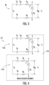
- FIG. 4 illustrates an alternative thermoelectric detector 114 in accordance with the present invention, which can be used in lieu of detector 90.
- a pair of similar sensing circuits 116a and 116b are provided.
- Sensing circuits 116a and 116b are both arranged to experience the same ambient temperature (i.e., the temperature of the vapor environment), but only junction T 2 of sensing circuit 116a is directly exposed to the vapor environment.
- sensing circuit 116b and junction T 1 of sensing circuit 116a are physically isolated from the vapor environment, such as by seals, covers, etc.
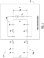
- FIG. 5 illustrates an alternative thermoelectric detector 122 in accordance with the present invention, which can be used in lieu of detector 90.
- a pair of similar sensing circuits 124a and 124b are connected to share a common junction T 1 .
- the common junction T 1 and junction T 2 of sensing circuit 124b are contained in a media isolated assembly 126. While only junction T 2 of sensing circuit 124a is directly exposed to the vapor environment, all junctions experience substantially the same temperature.
- T 1 is nonzero in this embodiment only when the base metal lead of sensing circuit 124a is in contact with the corrosive substance.
- FIG. 6 illustrates an alternative thermoelectric detector 130 in accordance with the present invention, which can be used in lieu of detector 90.
- a pair of similar sensing circuits 132a and 132b are connected together on their metal-type B sides.
- the voltage measuring device V and resistor Rs are connected across the metal-type A sides of sensing circuits 132a and 132b to form a common junction T 1 .
- the common junction T 1 and junction T 2 of sensing circuit 132b are contained in a media isolated assembly 134. While only junction T 2 of sensing circuit 132a is directly exposed to the vapor environment, all junctions experience substantially the same temperature.
- T 1 is nonzero in this embodiment only when the base metal lead of sensing circuit 132a is in contact with the corrosive substance.
- the heavier gage wire has a slower detection response time than the lighter gage wire.
- the time relationship between corrosion on each element provides a technique to evaluate the severity of the corrosive conditions.
- a microprocessor 142 is utilized to sample the outputs of sensing circuits 90a-c via a multiplexer ("MUX") 144.
- MUX multiplexer
- the functionality of microprocessor 142 and/or multiplexer 144 may in some cases be provided by suitable programming of tank monitor 72.
- Microprocessor 142 enables operation of multiplexer 144 via a signal provided by line 146 to the multiplexer's "ENABLE" input.
- the outputs of the respective sensing circuits 90a-c are selected by microprocessor 142 via selection lines collectively designated 148.
- the signals on selection lines 148 (designated S 1 through S N , with N being dependent on the number of sensing circuits in detector 140) inform multiplexer 144 which one of inputs C 1 through C 3 is active at any given time.
- the selected input is then provided at output D to microprocessor 142, e.g., via signal line 150.
- Inputs C 1 through C 3 are in electrical communication with the respective sensing circuits 90a through 90c.
- Respective amplifiers (or buffers) 152a, 152b, and 152c may be situated along the lines connecting sensing circuits 90a-c and their associated one of inputs C 1 through C 3 , if necessary or desired.
Description
- The present invention relates generally to equipment used in fuel dispensing environments. More specifically, the present invention relates to a fuel delivery system having the capability of detecting the presence of corrosives that might lead to reliability and maintenance issues.
- As is well known known, liquid fuel delivery systems typically include one or more fuel dispensers located in the forecourt area of a service station. The fuel dispensers are connected via piping with a source of the liquid fuel (e.g., a tank containing gasoline). Typically, the piping is located under the forecourt so as to feed the liquid fuel from an underground storage tank (UST). Multiple USTs may be provided for different types or grades of fuel. Fuel grades can be mixed as necessary or desired to yield still further grades of fuel.
- Modern fueling environments may store liquid fuels which are mixtures of gasoline and ethanol in various ratios, rather than "pure" gasoline. For example, E10 is a liquid fuel comprising 90% gasoline and 10% ethanol. As small amounts of water enter the storage tank containing a gasoline/ethanol mixture, the ethanol absorbs the water. Alternative fuels such as low sulfur diesel and biodiesel are also becoming more common.
- The introduction of various alternative and pollution reducing fuels (e.g., fuels with ethanol oxygenate) has created the potential for corrosion in fuel dispensing systems (especially when the fuel does not have a biological reducing inhibitor such as sulfur or includes a biologically supportive substance, such as ethanol). When it occurs, corrosion can result in an interruption of fueling operations, loss of sales, and possible damage. A fuel dispensing system according to the preamble of claim 1 is known from
US2014053943 A1 . - The present invention relates to a fuel dispensing system according to claim 1.
- In some exemplary embodiments, the thermoelectric detector is located in an upper portion of the fuel tank above a maximum fuel level. In some exemplary embodiments, the pump is a submersible turbine pump (STP) and the system further comprises an STP sump, further wherein the thermoelectric detector is located in an STP sump. In some exemplary embodiments, the thermoelectric detector is located in a fuel dispenser sump located below the fuel dispenser.
- The thermoelectric detector comprises a sensing circuit having a pair of junctions formed by interconnection of dissimilar conductors, the pair of junctions being configured to experience a substantially equivalent ambient temperature. In some exemplary embodiments, one of the pair of junctions is in direct contact with the fuel vapor and another of the pair of junctions is in indirect contact with the fuel vapor via a media isolated assembly. The media isolated assembly comprises an assembly configured to permit measurement of the temperature of said another of said pair of junctions without exposure to the vapor. The detector signal in such embodiments may originate at the another of the pair of junctions. A second sensing circuit having a pair of junctions formed by interconnection of dissimilar conductors may also be provided, one of the pair of junctions of the sensing circuit and one of the pair of junctions of the second sensing circuit being connected together.
- The corrosive detection assembly comprises at least one thermoelectric detector positioned to be in contact with fuel vapor in the fuel dispensing system, the thermoelectric detector producing a detector signal indicating presence of the corrosive substance. The thermoelectric detector includes a sensing circuit having a pair of junctions formed by interconnection of dissimilar conductors, the pair of junctions being configured to experience a substantially equivalent ambient temperature. Electronics in electrical communication with the thermoelectric detector are operative to interpret the detector signal and produce an output if the corrosive substance is present.
- According to an embodiment, a thermoelectric detector having a plurality of sensing circuits each with a different detection response time. For example, junctions of each such sensing circuit may be made of progressively heavier gage wire such that each heavier gage sensing circuit has a slower response time than the next smaller gage sensing circuit. The difference in time to detection between the sensing circuits is indicative of and related to the severity of the corrosive condition of the environment. That is, shorter detection times indicate higher concentration levels of corrosive substances.
- Those skilled in the art will appreciate the scope of the present invention and realize additional aspects thereof after reading the following detailed description of preferred embodiments in association with the accompanying drawing figures.
- A full and enabling disclosure of the present invention, including the best mode thereof directed to one skilled in the art, is set forth in the specification, which makes reference to the appended drawings, in which:
-
Figure 1 is a diagrammatic representation of fuel dispensing system including a corrosive detection assembly in accordance with an embodiment of the present invention. -
Figure 2 is a diagrammatic representation showing components of a corrosive detection assembly in accordance with an embodiment of the present invention. -
Figure 3 is a schematic diagram illustrating aspects of a detector circuit arrangement that may be used with one or more embodiments of the present invention. -
Figure 4 is a schematic diagram illustrating aspects of a detector circuit arrangement that may be used with one or more embodiments of the present invention. -
Figure 5 is a schematic diagram illustrating aspects of a detector circuit arrangement that may be used with one or more embodiments of the present invention. -
Figure 6 is a schematic diagram illustrating aspects of a detector circuit arrangement that may be used with one or more embodiments of the present invention. -
Figure 7 is a diagrammatic representation illustrating aspects of a detector circuit arrangement that may be used with one or more embodiments of the present invention. -
Figure 8 is a flowchart illustrating certain aspects of the operation of a corrosive detection assembly in accordance with one or more embodiments of the present invention. - Repeat use of reference characters in the present specification and drawings is intended to represent same or analogous features or elements of the invention.
- Reference will now be made in detail to presently preferred embodiments of the invention, one or more examples of which are illustrated in the accompanying drawings. Each example is provided by way of explanation of the invention, not limitation of the invention. In fact, it will be apparent to those skilled in the art that modifications and variations can be made in the present invention without departing from the scope of the claims.
- For instance, features illustrated or described as part of one embodiment may be used on another embodiment to yield a still further embodiment. Thus, it is intended that the present invention covers such modifications and variations as come within the scope of the present disclosure according to the appended claims.
- Certain fueling systems, particularly those that dispense fuel without a biological reducing inhibitor or fuel that includes a biologically supportive substance, may experience excessive or accelerated corrosion. The corrosion is often caused by the presence of bacteria that may be introduced into the fuel from the surrounding environment. For example, the bacteria may react with ethanol in the fuel to produce acid (e.g., acetic acid) that has a deleterious effect on equipment of the fuel dispensing system. Embodiments of this invention provides a corrosive detection assembly that can be used to detect presence of the corrosive substance so that remedial action can be taken.
- In this regard,
Figure 1 is a diagrammatic representation of afuel dispensing system 10 in a retail service station environment according to an aspect of the present invention. In general, fuel may travel from an underground storage tank (UST) 12 via main fuel piping 14, which may be a double-walled pipe having secondary containment as is well known, tofuel dispenser 16 and nozzle 18 for delivery. An exemplary underground fuel delivery system is illustrated inU.S. Pat. No. 6,435,204 . - More specifically, a submersible turbine pump (STP) 20 associated with the UST 12 is used to pump fuel to the
fuel dispenser 16. (In some embodiments, the fuel dispenser may be self-contained, meaning that fuel is drawn to the fuel dispenser by a pump unit positioned within the fuel dispenser housing.)STP 20 is comprised of adistribution head 22 containing power and control electronics that provide power through ariser 24 down to aboom 26, eventually reaching a turbine pump contained inside an outerturbine pump housing 28. STP 20 may preferably be the RED JACKET® submersible turbine pump, manufactured by the Veeder-Root Co. of Simsbury, Connecticut. There may be a plurality ofUSTs 12 andSTPs 20 in a service station environment if more than one type or grade offuel 30 is to be delivered by afuel dispenser 16. - The turbine pump operates to draw
fuel 30 upward from the UST 12 into theboom 26 andriser 24 for delivery to thefuel dispenser 16. AfterSTP 20 draws thefuel 30 into thedistribution head 22, thefuel 30 is carried throughSTP sump 32 to main fuel piping 14. Main fuel piping 14 carriesfuel 30 throughdispenser sump 34 tofuel dispenser 16 for eventual delivery.Dispenser sump 34 is adapted to capture any leakedfuel 30 that drains fromfuel dispenser 16 and its fuel handling components so thatfuel 30 is not leaked into the ground. - Main fuel piping 14 may then pass into
housing 36 offuel dispenser 16 through ashear valve 38. As is well known,shear valve 38 is designed to close the fuel flow path in the event of an impact to fueldispenser 16.U.S. Patent No. 8,291,928 discloses an exemplary secondarily-contained shear valve adapted for use in service station environments.Shear valve 38 contains an internal fuel flow path to carryfuel 30 from main fuel piping 14 tointernal fuel piping 40. - After
fuel 30 exits the outlet ofshear valve 38 and enters intointernal fuel piping 40, it may encounter aflow control valve 42 positioned upstream of aflow meter 44. (In some fuel dispensers,valve 42 may be positioned downstream of theflow meter 44.) In one embodiment,valve 42 may be a proportional solenoid controlled valve, such as described inU.S. Patent No. 5,954,080 ]. -
Flow control valve 42 is under control of acontrol system 46 via a flow controlvalve signal line 48. In this manner,control system 46 can control the opening and closing offlow control valve 42 to either allow fuel to flow or not flow throughmeter 44 and on to thehose 50 and nozzle 18.Control system 46 may be any suitable electronics with associated memory and software programs running thereon whether referred to as a processor, microprocessor, controller, microcontroller, or the like (which are intended herein as equivalent terms). In a preferred embodiment,control system 46 may be comparable to the microprocessor-based control systems used in CRIND and TRIND type units sold by Gilbarco Inc.Control system 46 typically controls other aspects offuel dispenser 16, such as valves, displays, and the like as is well understood. For example,control system 46 typically instructsflow control valve 42 to open when a fueling transaction is authorized. In addition,control system 46 may be in electronic communication with asite controller 52 via a fueldispenser communication network 54.Communication network 54 may be any suitable link, such as two wire, RS 422, Ethernet, wireless, etc. as needed or desired.Site controller 52 communicates withcontrol system 46 to control authorization of fueling transactions and other conventional forecourt control activities. For example, the site controller functions may be provided by the PASSPORTOO point-of-sale system manufactured by Gilbarco Inc. or by a separate forecourt controller. - The memory of control system 46 (and other memories discussed herein) may be any suitable memory or computer-readable medium as long as it is capable of being accessed by the control system, including random access memory (RAM), readonly memory (ROM), erasable programmable ROM (EPROM), or electrically EPROM (EEPROM), CD-ROM, DVD, or other optical disk storage, solid-state drive (SSD), magnetic disc storage, including floppy or hard drives, any type of suitable nonvolatile memories, such as secure digital (SD), flash memory, memory stick, or any other medium that may be used to carry or store computer program code in the form of computer-executable programs, instructions, or data.
Control system 46 may also include a portion of memory accessible only to controlsystem 46. -
Flow control valve 42 is contained below avapor barrier 56 in ahydraulics compartment 58 offuel dispenser 16.Control system 46 is typically located in anelectronics compartment 60 offuel dispenser 16 abovevapor barrier 56. Afterfuel 30 exits flowcontrol valve 42, it typically flows throughmeter 44, which preferably measures the flow rate offuel 30. In some embodiments,meter 44 may be capable of measuring the density and/or temperature of the flowing fuel.Flow meter 44 may be any suitable flow meter known to those of skill in the art, including positive displacement, inferential, and Coriolis mass flow meters, among others.Meter 44 typically compriseselectronics 62 that communicate information representative of the flow rate, density, and/or temperature of fuel to controlsystem 46 via asignal line 64. For example,electronics 62 may typically include a pulser as known to those skilled in the art. In this manner,control system 46 can update the total gallons (or liters) dispensed and the price of the fuel dispensed on an information display offuel dispenser 16. - As fuel leaves
flow meter 44 it enters aflow switch 66.Flow switch 66, which preferably comprises a one-way check valve that prevents rearward flow throughfuel dispenser 16, generates a flow switch communication signal via flowswitch signal line 68 to controlsystem 46 to communicate whenfuel 30 is flowing throughflow meter 44. The flow switch communication signal indicates to controlsystem 46 that fuel is actually flowing in the fuel delivery path and that subsequent signals fromflow meter 44 are due to actual fuel flow. - After
fuel 30 entersflow switch 66, it exits through internal fuel piping 40 to be delivered to a blend manifold 70. Blend manifold 70 receives fuels of varying octane levels from the various USTs and ensures that fuel of the octane level selected by the customer is delivered. After flowing through blend manifold 70,fuel 30 passes throughfuel hose 50 and nozzle 18 for delivery to the customer's vehicle. -
UST 12 includes an automatic tank gauge (ATG) system to monitor level offuel 30. The gauging system includes atank monitor 72 in electrical communication with a probe 74 (e.g., a magnetostrictive probe) such as via anappropriate signal line 76. In turn, tank monitor 72 is in electrical communication withsite controller 52, such as viasignal line 78. Preferably, tank monitor 72 is a microprocessor-based system having suitable program instructions stored in memory to perform the desired functions. For example, tank monitor 72 may comprise the TLS-450 or TLS-350 systems manufactured by Veeder-Root Company. -
Probe 74 includes aprobe shaft 80 that extends through the interior ofUST 12, as shown. Awater level float 82 andfuel level float 84 are able to slide along theshaft 80 as the liquid levels change. In particular,water level float 82 floats on the water-fuel interface so that the level of water in the bottom ofUST 12 can be detected. If the water level exceeds a threshold (such as if it is too near the inlet of pump housing 28), operation ofSTP 20 can be interrupted.Fuel level float 84 floats on top offuel 30 so that the amount of fuel inUST 12 can be determined. - As shown,
probe 74 includes anelectronics head 86 at the end ofprobe shaft 80, located external toUST 12 in awell 88.Head 86 generates signals provided to tank monitor 72 that are indicative of the locations offloats -
Fuel dispensing system 10 further comprises a corrosive detection assembly that is operative to detect the presence of a corrosive substance that may otherwise lead to premature corrosion within the fuel dispensing system. As will be explained, the corrosive detection system preferably includes at least onethermoelectric detector 90 situated in an electrolytic vapor environment within the fuel dispensing system. In this regard, evaporation of liquid fuel produces fuel vapor at various locations in the fuel dispensing system. A corrosive substance in the fuel will also be present in the vapor, where it is detected by thethermoelectric detector 90 as described more fully below. - In the illustrated embodiment, for example, a first thermoelectric detector 90a is located in the
ullage 92 ofUST 12 at a location above the highest expected level offuel 30. As is well known, hydrocarbon vapors produced by evaporation offuel 30 will be located inullage 92. If a corrosive substance is present in the vapor, detector 90a produces a signal that can be detected by suitable circuitry such as suitably programmed circuitry of tank monitor 72. Toward this end, detector 90a is in electrical communication with tank monitor 72 via acorresponding signal line 94. In addition, or in the alternative, one or more thermoelectric detectors may be situated in other locations in the fuel dispensing system. For example, the illustrated embodiment includes athermoelectric detector 90b inSTP sump 32 and/or athermoelectric detector 90c indispenser sump 34. - Referring now to
Figure 2 , certain additional details regarding an exemplarycorrosive detection assembly 100 of the present invention can be most easily explained. As shown,thermoelectric detector 90 is situated in avapor environment 102, which will be electrolytic in the presence of the corrosive substance. As a result, a signal indicating presence of the corrosive substance will be produced bydetector 90. While analog processing is possible within the scope of the present invention, the analog output ofdetector 90 is sampled and converted to a digital signal in the illustrated embodiment via a suitable analog-to-digital (A/D) converter 104. The output of A/D converter 104 is fed tocomparator circuitry 106, which in this embodiment includes amicroprocessor 108 and associatedmemory 110.Microprocessor 108 executes suitable program instructions to interpret the digitized signals fromdetector 90. If presence of the corrosive is detected, a signal indicative thereof can be provided toindicator 112 which may be any suitable device, circuitry, computer program, or other indicator that can be used to act upon the presence of the corrosive substance. For example,indicator 112 may be a visual or audible indicator to inform an operator that the corrosive material is present. In addition or in the alternative,indicator 112 may comprise a computer program that continuously tracks the amount of corrosive substance and generates action at the appropriate time. As noted above, the circuitry ofcorrosive detection assembly 100 may be incorporated intotank monitor 72. For example, tank monitor 72 can be programmed to perform the functions described in relation toFigure 2 in addition to other functions normally performed bytank monitor 72. - Certain aspects of a preferred implementation of
thermoelectric detector 90 can be explained with reference toFigure 3 . In this case,detector 90 utilizes the Seebeck effect in which a temperature dependent potential is generated by the formation of a bi-metal junction that is common to a class of temperature measuring sensors called thermocouples. The bi-metal junction is formed when two dissimilar metal wires are coupled by welding or other common connection methods. In a thermocouple, a temperature difference between the two ends of the connected wires produces a measurable voltage. - In this regard, voltage EA and resistance RA represent one electrical conductor of material type A (e.g., a base metal such as iron or copper). Similarly, EB and RB represent another electrical conductor of material type B (e.g., a noble metal or alloy such as nickel/chromium, platinum, etc.). T2 is the junction formed by coupling material type A to type B at one end, which in the case of a thermocouple would often be considered the "hot" junction. T1 is the junction formed by coupling material types A and B to measuring instrumentation at the other end, which in the case of a thermocouple would often be considered the "cold" junction. V is a voltage measuring device (e.g., a sampler) and Rs is a known large resistance intended to minimize the effects of RA and RB. In a thermocouple, the difference between EA and EB represents the magnitude of the temperature difference between T2 and T1.
- In accordance with embodiments of the present invention, the known temperature response of the bi-metal junction is not important. For example, junctions T1 and T2 may both be equally exposed to the vapor environment in a way that both will experience substantially the same ambient temperature. In the presence of the corrosive substance, a galvanically impressed voltage develops as the base metal is activated by contact with an electrolyte substance within the vapor environment. (The electrolyte dispersed by evaporation within the closed confines of the UST or the like is the same substance responsible for corrosion in the fuel delivery system.) With the base metal as the positive lead, the impressed voltage produced by formation of the galvanic circuit (represented by EA1) increases the overall voltage VAB at T1. Because the voltages EA and EB are minimized (due to no temperature differential between T1 and T2), EA1 can be easily detected.
-
Figure 4 illustrates an alternativethermoelectric detector 114 in accordance with the present invention, which can be used in lieu ofdetector 90. In this case, a pair ofsimilar sensing circuits 116a and 116b are provided.Sensing circuits 116a and 116b are both arranged to experience the same ambient temperature (i.e., the temperature of the vapor environment), but only junction T2 of sensing circuit 116a is directly exposed to the vapor environment. In this regard,sensing circuit 116b and junction T1 of sensing circuit 116a are physically isolated from the vapor environment, such as by seals, covers, etc. As shown, for example,sensing circuit 116b and junction T1 of sensing circuit 116a may be contained in a media isolatedassembly 118 which allows measurement of the same temperature as junction T2 of sensing circuit 116a without exposure to the vapor. As a result, only sensing circuit 116a will experience the galvanically impressed voltage EA1. A simple comparison of the output voltage VAB ofsensing circuits 116a and 116b can be used to determine whether EA1 is nonzero. -
Figure 5 illustrates an alternativethermoelectric detector 122 in accordance with the present invention, which can be used in lieu ofdetector 90. In this embodiment, a pair ofsimilar sensing circuits sensing circuit 124b are contained in a media isolatedassembly 126. While only junction T2 ofsensing circuit 124a is directly exposed to the vapor environment, all junctions experience substantially the same temperature. As will be appreciated, T1 is nonzero in this embodiment only when the base metal lead ofsensing circuit 124a is in contact with the corrosive substance. -
Figure 6 illustrates an alternativethermoelectric detector 130 in accordance with the present invention, which can be used in lieu ofdetector 90. In this embodiment, a pair ofsimilar sensing circuits 132a and 132b are connected together on their metal-type B sides. The voltage measuring device V and resistor Rs are connected across the metal-type A sides ofsensing circuits 132a and 132b to form a common junction T1. The common junction T1 and junction T2 ofsensing circuit 132b are contained in a media isolatedassembly 134. While only junction T2 of sensing circuit 132a is directly exposed to the vapor environment, all junctions experience substantially the same temperature. As will be appreciated, T1 is nonzero in this embodiment only when the base metal lead of sensing circuit 132a is in contact with the corrosive substance. -
Figure 7 illustrates another embodiment of athermoelectric detector 140 in accordance with the present invention. In this case,detector 140 comprises a plurality ofsensing circuits detector 90 discussed above. In this regard, the sensing circuits 90a-c each have a respective bimetal junction T2 exposed to the electrolytic vapor environment. Notably, however, wires forming the sensing circuits 90a-c have progressively heavier gage, such that 90b has heavier gage wire than 90a, and 90c has heavier gage wire than 90b. In the presence of a corrosive environment, each of the detection elements (sensing circuits) will experience corrosion at a detectably different rate. (Stated another way, the heavier gage wire has a slower detection response time than the lighter gage wire.) Because of the relationship between material mass and corrosive potential, for example the percentage of evaporated acetic acid, the time relationship between corrosion on each element provides a technique to evaluate the severity of the corrosive conditions. - In this embodiment, a
microprocessor 142 is utilized to sample the outputs of sensing circuits 90a-c via a multiplexer ("MUX") 144. As one skilled in the art will appreciate from the above discussion, the functionality ofmicroprocessor 142 and/ormultiplexer 144 may in some cases be provided by suitable programming of tank monitor 72.)Microprocessor 142 enables operation ofmultiplexer 144 via a signal provided byline 146 to the multiplexer's "ENABLE" input. The outputs of the respective sensing circuits 90a-c are selected bymicroprocessor 142 via selection lines collectively designated 148. The signals on selection lines 148 (designated S1 through SN, with N being dependent on the number of sensing circuits in detector 140) informmultiplexer 144 which one of inputs C1 through C3 is active at any given time. The selected input is then provided at output D tomicroprocessor 142, e.g., viasignal line 150. Inputs C1 through C3 are in electrical communication with the respective sensing circuits 90a through 90c. Respective amplifiers (or buffers) 152a, 152b, and 152c may be situated along the lines connecting sensing circuits 90a-c and their associated one of inputs C1 through C3, if necessary or desired. - In operation,
microprocessor 142 samples the outputs of sensing circuits 90a-c in rapid succession. The different detection readings of the sensing circuits 90a-c during any detection cycle, and the differences between the same sensing circuit 90a-c from one cycle to the next, is indicative of the severity of the corrosion. - Referring now to
Figure 8 , a method in accordance with the present invention of determining presence of a corrosive substance in a fuel dispensing system is illustrated. For example, the illustrated method may be practiced by program instructions running on the processor of tank monitor 72. After the process starts (as indicated at 160), detector signals (e.g., voltage signals from detector(s) 90) are received (as indicated at 162). This signal information is then compared against predetermined criteria (as indicated at 164). If the comparison shows presence of a corrosive and/or the severity of the corrosive (as indicated at step 166), an output is made to the indicator 112 (as shown at step 168). Otherwise, the process loops back for another comparison. The process ends atstep 170. - It can thus be seen that embodiments of the present invention provide a fuel dispensing system with a novel corrosive detection assembly. The embodiments depicted are presented by way of example only and are not intended as limitations upon the present invention. Thus, it should be understood by those of ordinary skill in this art that the present invention is not limited to these embodiments since modifications can be made within the scope of the claims.
Claims (16)
- A fuel dispensing system comprising:a fuel tank adapted to contain a quantity of fuel (30);a fuel dispenser (16) in fluid communication with said fuel tank via piping (14);a pump (20) operative to transfer fuel from said fuel tank to said fuel dispenser (16); anda corrosive detection assembly (100) operative to identify presence of a corrosive substance in said fuel (30), said corrosive detection assembly (100) having:
at least one detector (114,122,130,140) positioned to be in contact with fuel vapor in said fuel dispensing system, said detector (114,122,130,140) producing a detector signal indicating presence ofthe corrosive substance; and electronics (60) in electrical communication with said detector (114,122,130,140), said electronics (60) being operative to interpret said detector (114,122,130,140) signal and produce an output if the corrosive substance is present,characterised in thatsaid detector is a thermoelectric detector (114,122,130,140) comprising a sensing circuit (116a,124a,132a,90a) having a pair of junctions (T1,T2) formed by interconnection of dissimilar conductors, said pair of junctions (T1,T2) being configured to experience substantially the same ambient temperature. - A fuel dispensing system as set forth in claim 1, wherein said thermoelectric detector (114,122,130,140) is located in an upper portion of the fuel tank above a maximum fuel level.
- A fuel dispensing system as set forth in claim 1, wherein said pump (20) is a submersible turbine pump (STP) (20) and the system further comprises an STP sump (32), further wherein said thermoelectric detector (114,122,130,140) is located in an STP sump (32).
- A fuel dispensing system as set forth in claim 1, wherein said thermoelectric detector (114,122,130,140) is located in a fuel dispenser sump (34) located below said fuel dispenser (16).
- A fuel dispensing system as set forth in claim 1, wherein said at least one thermoelectric detector (114,122,130,140) comprises a plurality of thermoelectric detectors (114,122,130,140) at different locations in said fuel dispensing system.
- A fuel dispensing system as set forth in claim 1, wherein one of said pair of junctions (T1,T2) is in direct contact with the fuel vapor and another of said pair of junctions (T1,T2) is in indirect contact with the fuel vapor via a media isolated assembly (118,126,134), wherein the media isolated assembly (118,126,134) comprises an assembly configured to permit measurement of the temperature of said another of said pair of junctions without exposure to the fuel vapor.
- A fuel dispensing system as set forth in claim 6, wherein said detector signal originates at said another of said pair of junctions (T1,T2).
- A fuel dispensing system as set forth in claim 7, further comprising a second sensing circuit (116b,124b,132b) having a pair of junctions (T1,T2) formed by interconnection of dissimilar conductors, one of said pair of junctions (T1,T2) of said sensing circuit (116a,124a,132a) and one of said pair of junctions (T1,T2) of said second sensing circuit (116b,124b,132b)) being connected together.
- A fuel dispensing system as set forth in claim 1, wherein a first of said dissimilar conductors comprises a metal selected from the group consisting of iron and copper.
- A fuel dispensing system as set forth in claim 9, wherein a second of said dissimilar conductors comprises a noble metal.
- A fuel dispensing system as set forth in claim 10, wherein said second of said dissimilar conductors comprises platinum.
- A fuel dispensing system as set forth in claim 9, wherein said second of said dissimilar conductors comprises a nickel/chromium alloy.
- A fuel dispensing system as set forth in claim 1, wherein said thermoelectric detector (140) comprises a plurality of said sensing circuits (90a,90b,90c), said sensing circuits (90a,90b,90c) each having different gage dissimilar conductors from other of said sensing circuits (90a,90b,90c).
- A fuel dispensing system as set forth in claim 1, wherein said electronics comprise an analog-to-digital converter (104) operative to receive said detector signal in analog form and produce a digital output and comparator circuitry (106).
- A fuel dispensing system as set forth in claim 14, wherein said comparator circuitry (106) comprises a processor and memory.
- A fuel dispensing system as set forth in claim 1, wherein at least a portion of said electronics (60) are incorporated into a tank monitor device in electrical communication with a level gauge in said fuel tank.
Priority Applications (1)
| Application Number | Priority Date | Filing Date | Title |
|---|---|---|---|
| EP23197683.8A EP4345056A2 (en) | 2017-08-29 | 2018-08-29 | Fuel delivery system having corrosive detection assembly |
Applications Claiming Priority (2)
| Application Number | Priority Date | Filing Date | Title |
|---|---|---|---|
| US201762551567P | 2017-08-29 | 2017-08-29 | |
| PCT/US2018/048551 WO2019046431A1 (en) | 2017-08-29 | 2018-08-29 | Fuel delivery system having corrosive detection assembly |
Related Child Applications (2)
| Application Number | Title | Priority Date | Filing Date |
|---|---|---|---|
| EP23197683.8A Division-Into EP4345056A2 (en) | 2017-08-29 | 2018-08-29 | Fuel delivery system having corrosive detection assembly |
| EP23197683.8A Division EP4345056A2 (en) | 2017-08-29 | 2018-08-29 | Fuel delivery system having corrosive detection assembly |
Publications (3)
| Publication Number | Publication Date |
|---|---|
| EP3676880A1 EP3676880A1 (en) | 2020-07-08 |
| EP3676880A4 EP3676880A4 (en) | 2021-05-05 |
| EP3676880B1 true EP3676880B1 (en) | 2023-11-01 |
Family
ID=65434071
Family Applications (2)
| Application Number | Title | Priority Date | Filing Date |
|---|---|---|---|
| EP18850412.0A Active EP3676880B1 (en) | 2017-08-29 | 2018-08-29 | Fuel delivery system having corrosive detection assembly |
| EP23197683.8A Pending EP4345056A2 (en) | 2017-08-29 | 2018-08-29 | Fuel delivery system having corrosive detection assembly |
Family Applications After (1)
| Application Number | Title | Priority Date | Filing Date |
|---|---|---|---|
| EP23197683.8A Pending EP4345056A2 (en) | 2017-08-29 | 2018-08-29 | Fuel delivery system having corrosive detection assembly |
Country Status (6)
| Country | Link |
|---|---|
| US (1) | US11034573B2 (en) |
| EP (2) | EP3676880B1 (en) |
| CN (1) | CN111357125A (en) |
| BR (1) | BR112020003904A2 (en) |
| MX (1) | MX2020002225A (en) |
| WO (1) | WO2019046431A1 (en) |
Families Citing this family (2)
| Publication number | Priority date | Publication date | Assignee | Title |
|---|---|---|---|---|
| WO2014031389A1 (en) | 2012-08-22 | 2014-02-27 | Franklin Fueling Systems, Inc. | Method and apparatus for limiting acidic corrosion in fuel delivery systems |
| US11572267B2 (en) * | 2020-07-17 | 2023-02-07 | Veeder-Root Company | Fuel delivery system having printed circuit corrosion sensor |
Citations (2)
| Publication number | Priority date | Publication date | Assignee | Title |
|---|---|---|---|---|
| US2987685A (en) * | 1956-08-15 | 1961-06-06 | Pure Oil Co | Corrosion test probe |
| US4217544A (en) * | 1978-10-16 | 1980-08-12 | Shell Oil Company | Method and apparatus for improved temperature compensation in a corrosion measurement system |
Family Cites Families (24)
| Publication number | Priority date | Publication date | Assignee | Title |
|---|---|---|---|---|
| US3104355A (en) | 1955-04-18 | 1963-09-17 | Magna Products Inc | Corrosion measuring probe with a temperature compensating element in a wheatstone bridge and method of using same |
| US3936737A (en) | 1975-04-10 | 1976-02-03 | C.M.S. Inc. | Corrosion monitoring system |
| FR2382000A1 (en) | 1977-02-25 | 1978-09-22 | Auxitrol | THERMOCOUPLES RAMP FOR MEASURING THE AVERAGE OF SEVERAL TEMPERATURES |
| US5070024A (en) * | 1988-07-12 | 1991-12-03 | Gas Research Institute | Hydrocarbon detector utilizing catalytic cracking |
| US5288147A (en) * | 1992-11-09 | 1994-02-22 | Ta Instruments, Inc. | Thermopile differential thermal analysis sensor |
| US5954080A (en) | 1996-02-20 | 1999-09-21 | Gilbarco, Inc. | Gated proportional flow control valve with low flow control |
| AUPP040797A0 (en) | 1997-11-14 | 1997-12-11 | Bp Australia Limited | Fuel dispensing system |
| US6258253B1 (en) | 1999-04-15 | 2001-07-10 | The United States Of America As Represented By The Administrator Of The National Aeronautics And Space Administration | Vapor corrosion cell and method of using same |
| GB2349221B (en) | 1999-04-19 | 2003-10-15 | Cormon Ltd | Electrical resistance sensor and apparatus for monitoring corrosion |
| US7034553B2 (en) | 2003-12-05 | 2006-04-25 | Prodont, Inc. | Direct resistance measurement corrosion probe |
| US7946309B2 (en) | 2005-04-26 | 2011-05-24 | Veeder-Root Company | Vacuum-actuated shear valve device, system, and method, particularly for use in service station environments |
| GB0415862D0 (en) * | 2004-07-15 | 2004-08-18 | Boc Group Plc | Sensor |
| US20060018762A1 (en) * | 2004-07-22 | 2006-01-26 | Integral Technologies, Inc. | Low cost electrostatic discharge-proof pumps manufactured from conductive loaded resin-based materials |
| US8235627B2 (en) * | 2005-12-08 | 2012-08-07 | Ellis Mark T | System and method for detecting and remediating contamination |
| US7915901B2 (en) | 2008-02-01 | 2011-03-29 | M. J. Schiff & Associates, Inc. | Low-profile electrical resistance corrosion sensor |
| US20090311772A1 (en) * | 2008-04-25 | 2009-12-17 | E-Fuel Corporation | Micro refinery for ethanol production |
| US8770237B2 (en) | 2009-10-19 | 2014-07-08 | Veeder-Root Company | Vapor recovery pump regulation of pressure to maintain air to liquid ratio |
| US9739512B2 (en) | 2010-08-09 | 2017-08-22 | Empire Technology Development Llc | Control system for thermoelectric devices |
| CN103907008A (en) * | 2011-06-21 | 2014-07-02 | 俄亥俄州立大学 | Device and method for monitoring interaction between a fluid and a wall |
| US20130047963A1 (en) | 2011-08-26 | 2013-02-28 | Continental Automotive Systems Us, Inc. | Warranty violation detection system for disallowed fuels |
| WO2014031389A1 (en) * | 2012-08-22 | 2014-02-27 | Franklin Fueling Systems, Inc. | Method and apparatus for limiting acidic corrosion in fuel delivery systems |
| US9530290B2 (en) | 2013-01-18 | 2016-12-27 | Fuel Guard Systems Corporation | Apparatuses and methods for providing visual indication of dynamic process fuel quality delivery conditions with use of multiple colored indicator lights |
| WO2016130508A1 (en) | 2015-02-09 | 2016-08-18 | Veeder-Root Company | Breakaway coupling monitoring |
| US11352248B2 (en) * | 2017-03-07 | 2022-06-07 | Franklin Fueling Systems, Llc | Method and apparatus for limiting acidic corrosion and contamination in fuel delivery systems |
-
2018
- 2018-08-29 BR BR112020003904-7A patent/BR112020003904A2/en active Search and Examination
- 2018-08-29 MX MX2020002225A patent/MX2020002225A/en unknown
- 2018-08-29 EP EP18850412.0A patent/EP3676880B1/en active Active
- 2018-08-29 EP EP23197683.8A patent/EP4345056A2/en active Pending
- 2018-08-29 US US16/116,400 patent/US11034573B2/en active Active
- 2018-08-29 CN CN201880064021.6A patent/CN111357125A/en active Pending
- 2018-08-29 WO PCT/US2018/048551 patent/WO2019046431A1/en unknown
Patent Citations (2)
| Publication number | Priority date | Publication date | Assignee | Title |
|---|---|---|---|---|
| US2987685A (en) * | 1956-08-15 | 1961-06-06 | Pure Oil Co | Corrosion test probe |
| US4217544A (en) * | 1978-10-16 | 1980-08-12 | Shell Oil Company | Method and apparatus for improved temperature compensation in a corrosion measurement system |
Also Published As
| Publication number | Publication date |
|---|---|
| EP3676880A1 (en) | 2020-07-08 |
| EP3676880A4 (en) | 2021-05-05 |
| WO2019046431A1 (en) | 2019-03-07 |
| US11034573B2 (en) | 2021-06-15 |
| MX2020002225A (en) | 2020-12-09 |
| CN111357125A (en) | 2020-06-30 |
| US20190062142A1 (en) | 2019-02-28 |
| EP4345056A2 (en) | 2024-04-03 |
| BR112020003904A2 (en) | 2020-11-03 |
Similar Documents
| Publication | Publication Date | Title |
|---|---|---|
| US6929018B2 (en) | Underground storage tank metering system in a service station environment | |
| US10619461B2 (en) | Method and apparatus for separating and measuring multiphase immiscible fluid mixtures | |
| US10359306B2 (en) | Systems and methods for testing petroleum wells | |
| EP3676880B1 (en) | Fuel delivery system having corrosive detection assembly | |
| EP1292402B1 (en) | Method and system for cleaning beverage tubes and a detector unit used in the system | |
| US20110094287A1 (en) | System and method for automated calibration of a fuel flow meter in a fuel dispenser | |
| US20050039546A1 (en) | Increased sensitivity for liquid meter | |
| US20210101795A1 (en) | Blending apparatus and method | |
| US20120261437A1 (en) | Method and apparatus for prevention and detection of phase separation in storage tanks | |
| CN110300723B (en) | Fuel charger with fuel analyzer | |
| US20130008247A1 (en) | Magnetostrictive probe fuel quality sensor retrofit assembly | |
| WO2008130513A1 (en) | System and method for detecting pressure variations in fuel dispensers to more accurately measure fuel delivered | |
| JP2009543078A (en) | Method and apparatus for measuring the level of pressurized liquid in a siphon container | |
| US11242238B2 (en) | Fuel delivery system having additive injection assembly | |
| US11572267B2 (en) | Fuel delivery system having printed circuit corrosion sensor | |
| US20210116345A1 (en) | Onboard apparatus, system, and method for automatically dynamically evaluating characteristics of a non-homogenous liquid during loading and unloading of a transport container | |
| EP0961190A1 (en) | Fuel blending apparatus using octane levels | |
| WO2023018764A1 (en) | Fuel dispenser having flow meter autocalibration capability | |
| Wrightsman | 18. Custody Transfer by Displacement Meters |
Legal Events
| Date | Code | Title | Description |
|---|---|---|---|
| STAA | Information on the status of an ep patent application or granted ep patent |
Free format text: STATUS: THE INTERNATIONAL PUBLICATION HAS BEEN MADE |
|
| PUAI | Public reference made under article 153(3) epc to a published international application that has entered the european phase |
Free format text: ORIGINAL CODE: 0009012 |
|
| STAA | Information on the status of an ep patent application or granted ep patent |
Free format text: STATUS: REQUEST FOR EXAMINATION WAS MADE |
|
| 17P | Request for examination filed |
Effective date: 20200228 |
|
| AK | Designated contracting states |
Kind code of ref document: A1 Designated state(s): AL AT BE BG CH CY CZ DE DK EE ES FI FR GB GR HR HU IE IS IT LI LT LU LV MC MK MT NL NO PL PT RO RS SE SI SK SM TR |
|
| AX | Request for extension of the european patent |
Extension state: BA ME |
|
| DAV | Request for validation of the european patent (deleted) | ||
| DAX | Request for extension of the european patent (deleted) | ||
| A4 | Supplementary search report drawn up and despatched |
Effective date: 20210331 |
|
| RIC1 | Information provided on ipc code assigned before grant |
Ipc: G01N 25/00 20060101AFI20210326BHEP Ipc: H01L 35/28 20060101ALI20210326BHEP Ipc: G01N 33/22 20060101ALI20210326BHEP Ipc: G01N 25/18 20060101ALI20210326BHEP Ipc: B67D 7/32 20100101ALI20210326BHEP Ipc: B67D 7/04 20100101ALI20210326BHEP Ipc: B67D 7/68 20100101ALI20210326BHEP Ipc: B67D 7/08 20100101ALN20210326BHEP |
|
| REG | Reference to a national code |
Ref document number: 602018060549 Country of ref document: DE Ref country code: DE Ref legal event code: R079 Free format text: PREVIOUS MAIN CLASS: H01L0035280000 Ipc: G01N0025000000 |
|
| GRAP | Despatch of communication of intention to grant a patent |
Free format text: ORIGINAL CODE: EPIDOSNIGR1 |
|
| STAA | Information on the status of an ep patent application or granted ep patent |
Free format text: STATUS: GRANT OF PATENT IS INTENDED |
|
| RIC1 | Information provided on ipc code assigned before grant |
Ipc: B67D 7/08 20100101ALN20230427BHEP Ipc: B67D 7/68 20100101ALI20230427BHEP Ipc: B67D 7/04 20100101ALI20230427BHEP Ipc: B67D 7/32 20100101ALI20230427BHEP Ipc: G01N 25/18 20060101ALI20230427BHEP Ipc: G01N 33/22 20060101ALI20230427BHEP Ipc: G01N 25/00 20060101AFI20230427BHEP |
|
| INTG | Intention to grant announced |
Effective date: 20230516 |
|
| P01 | Opt-out of the competence of the unified patent court (upc) registered |
Effective date: 20230606 |
|
| GRAS | Grant fee paid |
Free format text: ORIGINAL CODE: EPIDOSNIGR3 |
|
| GRAA | (expected) grant |
Free format text: ORIGINAL CODE: 0009210 |
|
| STAA | Information on the status of an ep patent application or granted ep patent |
Free format text: STATUS: THE PATENT HAS BEEN GRANTED |
|
| AK | Designated contracting states |
Kind code of ref document: B1 Designated state(s): AL AT BE BG CH CY CZ DE DK EE ES FI FR GB GR HR HU IE IS IT LI LT LU LV MC MK MT NL NO PL PT RO RS SE SI SK SM TR |
|
| REG | Reference to a national code |
Ref country code: GB Ref legal event code: FG4D |
|
| REG | Reference to a national code |
Ref country code: CH Ref legal event code: EP |
|
| REG | Reference to a national code |
Ref country code: IE Ref legal event code: FG4D |
|
| REG | Reference to a national code |
Ref country code: DE Ref legal event code: R096 Ref document number: 602018060549 Country of ref document: DE |
|
| REG | Reference to a national code |
Ref country code: LT Ref legal event code: MG9D |
|
| REG | Reference to a national code |
Ref country code: NL Ref legal event code: MP Effective date: 20231101 |
|
| PG25 | Lapsed in a contracting state [announced via postgrant information from national office to epo] |
Ref country code: GR Free format text: LAPSE BECAUSE OF FAILURE TO SUBMIT A TRANSLATION OF THE DESCRIPTION OR TO PAY THE FEE WITHIN THE PRESCRIBED TIME-LIMIT Effective date: 20240202 |
|
| PG25 | Lapsed in a contracting state [announced via postgrant information from national office to epo] |
Ref country code: IS Free format text: LAPSE BECAUSE OF FAILURE TO SUBMIT A TRANSLATION OF THE DESCRIPTION OR TO PAY THE FEE WITHIN THE PRESCRIBED TIME-LIMIT Effective date: 20240301 |
|
| PG25 | Lapsed in a contracting state [announced via postgrant information from national office to epo] |
Ref country code: LT Free format text: LAPSE BECAUSE OF FAILURE TO SUBMIT A TRANSLATION OF THE DESCRIPTION OR TO PAY THE FEE WITHIN THE PRESCRIBED TIME-LIMIT Effective date: 20231101 |
|
| REG | Reference to a national code |
Ref country code: AT Ref legal event code: MK05 Ref document number: 1627753 Country of ref document: AT Kind code of ref document: T Effective date: 20231101 |
|
| PG25 | Lapsed in a contracting state [announced via postgrant information from national office to epo] |
Ref country code: NL Free format text: LAPSE BECAUSE OF FAILURE TO SUBMIT A TRANSLATION OF THE DESCRIPTION OR TO PAY THE FEE WITHIN THE PRESCRIBED TIME-LIMIT Effective date: 20231101 |
|
| PG25 | Lapsed in a contracting state [announced via postgrant information from national office to epo] |
Ref country code: AT Free format text: LAPSE BECAUSE OF FAILURE TO SUBMIT A TRANSLATION OF THE DESCRIPTION OR TO PAY THE FEE WITHIN THE PRESCRIBED TIME-LIMIT Effective date: 20231101 |