EP3676794B1 - Zoom sur une image ou une vidéo omnidirectionnelle - Google Patents
Zoom sur une image ou une vidéo omnidirectionnelle Download PDFInfo
- Publication number
- EP3676794B1 EP3676794B1 EP18756474.5A EP18756474A EP3676794B1 EP 3676794 B1 EP3676794 B1 EP 3676794B1 EP 18756474 A EP18756474 A EP 18756474A EP 3676794 B1 EP3676794 B1 EP 3676794B1
- Authority
- EP
- European Patent Office
- Prior art keywords
- zoomed
- image data
- view
- region
- user
- Prior art date
- Legal status (The legal status is an assumption and is not a legal conclusion. Google has not performed a legal analysis and makes no representation as to the accuracy of the status listed.)
- Active
Links
Images


Classifications
-
- G—PHYSICS
- G06—COMPUTING OR CALCULATING; COUNTING
- G06T—IMAGE DATA PROCESSING OR GENERATION, IN GENERAL
- G06T3/00—Geometric image transformations in the plane of the image
- G06T3/40—Scaling of whole images or parts thereof, e.g. expanding or contracting
-
- A—HUMAN NECESSITIES
- A63—SPORTS; GAMES; AMUSEMENTS
- A63F—CARD, BOARD, OR ROULETTE GAMES; INDOOR GAMES USING SMALL MOVING PLAYING BODIES; VIDEO GAMES; GAMES NOT OTHERWISE PROVIDED FOR
- A63F13/00—Video games, i.e. games using an electronically generated display having two or more dimensions
- A63F13/20—Input arrangements for video game devices
- A63F13/21—Input arrangements for video game devices characterised by their sensors, purposes or types
- A63F13/212—Input arrangements for video game devices characterised by their sensors, purposes or types using sensors worn by the player, e.g. for measuring heart beat or leg activity
-
- A—HUMAN NECESSITIES
- A63—SPORTS; GAMES; AMUSEMENTS
- A63F—CARD, BOARD, OR ROULETTE GAMES; INDOOR GAMES USING SMALL MOVING PLAYING BODIES; VIDEO GAMES; GAMES NOT OTHERWISE PROVIDED FOR
- A63F13/00—Video games, i.e. games using an electronically generated display having two or more dimensions
- A63F13/50—Controlling the output signals based on the game progress
- A63F13/52—Controlling the output signals based on the game progress involving aspects of the displayed game scene
- A63F13/525—Changing parameters of virtual cameras
- A63F13/5255—Changing parameters of virtual cameras according to dedicated instructions from a player, e.g. using a secondary joystick to rotate the camera around a player's character
-
- G—PHYSICS
- G06—COMPUTING OR CALCULATING; COUNTING
- G06T—IMAGE DATA PROCESSING OR GENERATION, IN GENERAL
- G06T3/00—Geometric image transformations in the plane of the image
- G06T3/04—Context-preserving transformations, e.g. by using an importance map
-
- A—HUMAN NECESSITIES
- A63—SPORTS; GAMES; AMUSEMENTS
- A63F—CARD, BOARD, OR ROULETTE GAMES; INDOOR GAMES USING SMALL MOVING PLAYING BODIES; VIDEO GAMES; GAMES NOT OTHERWISE PROVIDED FOR
- A63F2300/00—Features of games using an electronically generated display having two or more dimensions, e.g. on a television screen, showing representations related to the game
- A63F2300/80—Features of games using an electronically generated display having two or more dimensions, e.g. on a television screen, showing representations related to the game specially adapted for executing a specific type of game
- A63F2300/8082—Virtual reality
-
- G—PHYSICS
- G02—OPTICS
- G02B—OPTICAL ELEMENTS, SYSTEMS OR APPARATUS
- G02B27/00—Optical systems or apparatus not provided for by any of the groups G02B1/00 - G02B26/00, G02B30/00
- G02B27/01—Head-up displays
- G02B27/017—Head mounted
-
- G—PHYSICS
- G06—COMPUTING OR CALCULATING; COUNTING
- G06T—IMAGE DATA PROCESSING OR GENERATION, IN GENERAL
- G06T2207/00—Indexing scheme for image analysis or image enhancement
- G06T2207/10—Image acquisition modality
- G06T2207/10004—Still image; Photographic image
-
- G—PHYSICS
- G06—COMPUTING OR CALCULATING; COUNTING
- G06T—IMAGE DATA PROCESSING OR GENERATION, IN GENERAL
- G06T2207/00—Indexing scheme for image analysis or image enhancement
- G06T2207/10—Image acquisition modality
- G06T2207/10016—Video; Image sequence
Definitions
- the invention relates to a method of zooming an omnidirectional image or video which is represented by image data and is viewable in virtual or augmented reality on the basis of the image data being i) projected onto a virtual body in a virtual environment and ii) rendered from a viewpoint within or facing the virtual body.
- the invention further relates to a computer program comprising instructions for causing a processor system to perform the method.
- the invention further relates to a rendering system configured for rendering the virtual environment, and to a sender system configured for providing image data of an omnidirectional image or video to the rendering system.
- Virtual Reality involves the use of computer technology to simulate a user's physical presence in a virtual environment
- Augmented Reality uses computer technology to augment a user's view of the physical real-world environment by overlaying a virtual environment over, or in another manner combining the virtual environment with the user's view of the physical real-world environment.
- These environments may be rendered by VR or AR rendering systems or devices, and displayed to the user using VR or AR displays, including but not limited to Head-Mounted Displays (HMD), holographic displays and curved or other types of displays providing an immersive experience to the user, including but not limited large-screen or multi-screen displays such as CAVE or IMAX cinema displays.
- HMD Head-Mounted Displays
- holographic displays and curved or other types of displays providing an immersive experience to the user, including but not limited large-screen or multi-screen displays such as CAVE or IMAX cinema displays.
- the term 'omnidirectional' may refer to the image or video providing an immersive experience when displayed using a VR or AR display, e.g., by matching or exceeding the field-of-view of such a display.
- the omnidirectional image or video may provide an at least 180 degree view of a scene.
- the omnidirectional image or video may even provide a larger view of the scene, e.g., up to 360 degrees, thereby providing an even more immersive experience to the user.
- rendering an omnidirectional image or video in a virtual or augmented environment involves projecting the image data of the omnidirectional image or video onto a virtual body, such as a sphere, and rendering the projected image data from a viewpoint within or facing the virtual body.
- a 360° video is usually created by stitching multiple images together, e.g., two 180° images captured using fisheye lenses.
- the video images are typically mapped onto a virtual body, which may be a sphere, a box or other geometrical primitive or shape. Having done so, the projected image data may be rendered from a viewpoint within or facing the virtual body.
- zooming-in may allow a user to temporarily view a detailed part of a high-resolution 360° video which may otherwise be difficult to perceive.
- various reasons may exist for zooming an omnidirectional image or video, including but not limited to:
- YouTube allows users to view omnidirectional video using a HMD.
- YouTube offered zoom-in functionality, by which a user's previous non-zoomed view is replaced by a zoomed-in view of the omnidirectional video.
- a disadvantage of this type of zooming is that the user may lose his/her original reference point and experience a change in view which does not match his/her physical movement. It is known from " Minimizing cyber sickness in head mounted display systems: design guidelines and applications" by Porcino et al., IEEE 5th International Conference on Serious Games and Applications for Health, 2017 , that this type of incongruence is likely to cause or contribute to nausea of the user. Disadvantageously, in the zoomed-in view, the regular rotation of the head is amplified by the zoom factor, resulting in unnatural movement, which, when combined with the loss of reference points at the edge of the field-of-view, will likely contribute to the nausea of the user. Porcino et al. also note that, in general, (virtual) camera movement which is not initiated by the user will likely be uncomfortable for the user.
- Huiwen Chang ET AL "Panning and Zooming High-Resolution Panoramas in Virtual Reality Devices", Proceedings of the 30th Annual ACM Symposium on User Interface Software and Technology, UIST '17, 21 August 2017 (2017-08-21), pages 279-288, XP055421218, New York, USA , https://qfx.cs.princeton.edu/pubs/Chanq 2017 PAZ/uist2017.pdf , introduces and tests new interface modalities for exploring high resolution panoramic imagery in VR. It is demonstrated that limiting the visual FOV of the zoomed in imagery to the central portion of the visual field, and modulating the transparency or zoom level of the imagery during rapid panning, reduce simulator sickness and help with targeting tasks.
- Tiled display walls offer a large workspace that can be navigated physically by the user. Based on head tracking information, the physical characteristics of the tiled display and the formulation of visual acuity, an out-of-core gigapixel rendering scheme is guided by delivering high levels of detail only in places where it is perceivable to the user.
- This principle is applied to gigapixel image rendering through adaptive level of detail selection. Additionally, an acuity-driven tessellation scheme is developed for high-quality Focus-and-Context (F+C) lenses that significantly reduces visual artifacts while accurately capturing the underlying lens function.
- F+C Focus-and-Context
- a specialized camera mount in combination with an automated pipeline for alignment, exposure compensation, and stitching, provide the means to acquire Gigapixel images with a standard camera and lens. The viewer enables exploration of such images at interactive rates over a network, while dynamically and smoothly interpolating the projection between perspective and curved projections, and simultaneously modifying the tone-mapping to ensure an optimal view of the portion of the scene being viewed.
- a transitory or non-transitory computer-readable medium comprising a computer program.
- the computer program comprises instructions for causing a processor system to perform the method.
- a rendering system is provided.
- a sender system is provided.
- the above measures involve providing zooming functionality for an omnidirectional video or image.
- Such omnidirectional video or image may be displayed to a user by the image data being projected within a virtual environment onto a virtual body, such as a sphere, and the virtual environment being rendered from a viewpoint within or facing the virtual body.
- a rendered image may be obtained which may then be displayed to the user.
- the rendering is performed on a periodic basis and the viewpoint is that of a virtual camera in the virtual environment which represents the viewpoint of the user.
- the viewing direction of the virtual camera may be adjusted in response to a head rotation of the user. In case the user wears an HMD, such head rotation may be measured by a sensor in the HMD, but various other techniques exist as well for, in general, measuring the viewing direction of a user. It will be appreciated that the functionality described in this paragraph is known per se.
- the above measures provides as output a rendered image which comprises a zoomed portion which provides a zoomed view of the region, and a non-zoomed portion shown simultaneously with the zoomed portion.
- a rendered image which comprises a zoomed portion which provides a zoomed view of the region, and a non-zoomed portion shown simultaneously with the zoomed portion.
- an area bordering the zoomed region is shown, which includes but is not limited to the periphery of the zoomed region.
- the zoomed-in portion is a center portion of the rendered image
- the non-zoomed portion is a periphery around the center portion in the rendered image.
- the non-zoomed portion may be the center portion and the zoomed-out portion may be the periphery around the center portion.
- providing the zoomed view of the region may comprise processing the image data before the image data is projected onto the virtual body, or adjusting said projection of the image data, to establish the zoomed view of the region on a surface of the virtual body.
- the zoomed-view may be provided on the surface of the virtual body, e.g., by pre-processing the image data or by adjusting the projection thereof onto the virtual body. For the latter, use may be made by techniques described in the co-pending application ⁇ Programmable Projection Metadata> .
- This embodiment may have as advantage that it is not needed to adjust the virtual environment, the virtual body nor the rendering.
- zooming functionality may be provided for rendering systems in which it is not possible nor desired to adjust the virtual environment, the virtual body or the rendering.
- the pre-processing of the image data may be performed by the sender system or other system, in which case it may not be needed for the rendering system to perform any specific operations for providing the zooming functionality.
- the obtaining the user input comprises obtaining a measurement from a head-tracking system which is indicative of a translational and/or rotational movement of a head of the user.
- Head-tracking systems are known per se, and may, using sensors such as image sensors, accelerometers, gyroscopes, etc., provide measurements indicative of the position and/or movement of the user's head. Examples of movement-related measurements include measurements of velocity and acceleration.
- the zooming functionality is controlled by the head movement or head rotation of the user. For example, the zoom factor may be selected (inversely) proportional to the amount of head movement of the user.
- controlling the zooming functionality comprises selecting the size of the zoom region inversely proportional to the amount of head movement or acceleration of the user. For example, the zoom region may decrease when the user moves or accelerates his head so the user experiences a larger non-zoomed region to reduce or prevent nausea. Again, above a certain threshold, the zoom region may be switched to zero or effectively disabled.
- the head-tracking system may be comprised partially or completely in a head-mounted display. The head-tracking system may also be separate from a head-mounted display, e.g., based on one or more cameras or sensors tracking the head movement.
- obtaining the user input may comprise detecting a gaze of a user to identify a gaze point of the user with respect the rendered image.
- the gaze point may be used to determine of which region the zoomed-in view is to be provided.
- other aspects of the zooming may be controlled by gaze.
- the zooming functionality may be invoked in response to a steady gaze.
- the zoom factor may be gradually increased while the gaze is held steady.
- the zoom region may be gradually increased while the gaze is held steady.
- the zooming functionality may be based on user settings. For example, the gradual increase of zoom factor or zoom region size in response to head movement may be capped or enhanced based on user settings or technical limits. Also the speed of change such as the speed of increase may be determined by user settings, e.g., to optimize for the user's susceptibility to nausea.
- the image data may be obtained by layered video comprising a base layer and a zoom layer, wherein the zoom layer may provide an equal or higher resolution representation of the region to be zoomed than the base layer, wherein providing the zoomed portion of the rendered image may comprise selecting image data from the zoom layer and wherein providing the non-zoomed portion may comprise selecting image data from the base layer.
- the embodiments above are applicable to both monoscopic (e.g. a television screen) and stereoscopic viewing (e.g. a VR-headset).
- the stereoscopic images seen by the user may be different for each eye. This may create a 3D-effect, which may allow the user to look to the sides of the zoomed area.
- the following embodiments involve or relate to providing zooming functionality for an omnidirectional video or image.
- Such omnidirectional video or image may be displayed by the image data being projected onto a virtual body, such as a sphere, and the virtual environment being rendered from a viewpoint within or facing the virtual body.
- a rendered image may be obtained which may then be displayed to the user using a display, such as a head-mounted display (HMD).
- HMD head-mounted display
- the virtual environment may be an environment in which the virtual body is defined, e.g., as a geometric object in three-dimensional (3D) space, and which may, but does not need to, comprise other virtual objects.
- the term 'virtual' is used to indicate that the objects are not physical objects but rather defined by data.
- the virtual environment may comprise avatars of users participating in a communication session.
- the virtual environment may also be a representation of a physical real-world environment.
- the virtual environment may also be registered with the physical real-world environment to display objects contained therein in an augmented manner, e.g., as overlays, with the user's view of the real-world environment.
- the rendering may be performed by a rendering system, and the image data may be provided to the rendering system by streaming via a network.
- Fig. 1 provides a general overview of such an embodiment.
- a sender system 100 is shown which may be configured for providing image data 112 of the omnidirectional video or image to a rendering system 200 via a network 150.
- Fig. 1 further shows the rendering system 200 providing the rendered image(s) in the form of display data 232 to a HMD 240 which may be worn by a user 250 and connected to the rendering system.
- Fig. 1 further illustrates signalling between the sender system 100 and the rendering system 200, e.g., by way of the sender system 100 providing signalling data 114 to the rendering system 200 and the rendering system providing signalling data 212 to the sender system. Such signalling may be carried out in some embodiments and will be described further onwards.
- Streaming an omnidirectional video or image is known per se.
- a 360° video is typically created by stitching multiple video images together, e.g., two 180° video images captured using fisheye lenses.
- the term 'video image' refers to the image being of a video, e.g., a video frame.
- the stitching may be performed at the sender side, e.g., by the sender system 100 or another system.
- the image data 112 which is transmitted may represent the entire omnidirectional video image.
- only those parts of the omnidirectional video or image may be transmitted that are currently visible to a user of the rendering system, possibly including the image data of a so-termed 'guard-band' around the visible parts.
- Fig. 2 shows an example of the latter type of transmission by showing an omnidirectional video image 300, which may be spatially segmented into a plurality of tiles, e.g., as indicated by the gridlines forming a two-dimensional array (A-R, 1-7). Each tile may be represented by a different video stream.
- the rendering system may determine that another video stream is needed (henceforth also simply referred to as 'new' video stream) and switch to the new video stream by requesting the new video stream from the sender system.
- the field of view of the HMD 240 may encompass several tiles 310 at a time. As such, several video streams may be streamed concurrently to the rendering system.
- zooming functionality with respect to an omnidirectional video, whether or not it is streamed and in which form.
- a user may wish to obtain a zoomed-in view of a region 320 which is located in the current field of view of the user, e.g., as currently displayed by the HMD 240.
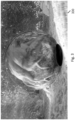
- Fig. 3 shows a rendered image 330, which may be obtained after image data of the omnidirectional video is projected onto a virtual body, e.g., a sphere, and rendered from a viewpoint within or facing the virtual body. Such rendering is known per se in the field of virtual reality.
- the rendered image 330 may be displayed by the head-mounted display, and is shown to provide a zoomed-in view of a region by comprising, in addition to a non-zoomed portion 350, a zoomed-in portion 340 which provides the zoomed view of the region.
- the term 'non-zoomed' may refer to a presentation which is obtained when the zooming functionality is not invoked, e.g., a default view, or a view having a lower zoom factor than the zoomed-in view.
- the region to be zoomed may be selected in various ways, e.g., automatically or by user selection.
- the zooming functionality may be implemented in various ways, e.g., by deforming the image data before or during projection onto the virtual body, by deforming or adjusting the virtual body, etc.
- Various different examples and embodiments are described with reference to Fig. 6 and onwards.
- Fig. 4 shows a more detailed view of the sender system 100 previously shown in Fig. 1 .
- the sender system 100 may comprise a network interface 110 for communicating with the rendering system 200 via one or more networks.
- the network interface 110 may take any suitable form, including but not limited to a wireless network interface, e.g., based on Wi-Fi, Bluetooth, ZigBee, 4G mobile communication or 5G mobile communication, or a wired network interface, e.g., based on Ethernet or optical fiber.
- the network interface 110 may be a local area network (LAN) network interface but also a network interface to a wide area network (WAN), e.g., the Internet.
- LAN local area network
- WAN wide area network
- the sender system 100 comprising a storage 130, such as internal memory, a hard disk, a solid state drive, or an array thereof, which may comprise the image data of the omnidirectional image or video and from which the image data may be retrieved to be provided to the rendering system 200.
- a storage 130 such as internal memory, a hard disk, a solid state drive, or an array thereof, which may comprise the image data of the omnidirectional image or video and from which the image data may be retrieved to be provided to the rendering system 200.
- the image data may be retrieved by the sender system 100 from a different source, e.g., from an external storage connected to the sender system 100.
- the sender system 100 may further comprise a processor 120 which may be configured, e.g., by hardware design or software, to perform the operations described with reference to Fig. 1 and others in as far as pertaining to the providing of the image data of the omnidirectional image or video to the rendering system 200, and in some embodiments, to the enabling of zooming of the omnidirectional image or video within the virtual environment.
- the processor 120 may be embodied by a single Central Processing Unit (CPU), but also by a combination or system of such CPUs and/or other types of processing units.
- CPU Central Processing Unit
- the sender system 100 may be embodied by a (single) device or apparatus.
- the sender system 100 may be embodied as a network server.
- the sender system 100 may also be embodied by a distributed system of such devices or apparatuses. An example of the latter may be the functionality of the sender system 100 being distributed over different network elements in a network.
- Fig. 5 shows a more detailed view of the rendering system 200.
- the rendering system 200 may comprise a network interface 210 for receiving data from the sender system 100, such as the image data and the signalling data as described with reference to Fig. 1 , via one or more networks.
- the network interface 210 may also be used for sending data to the sender system 100 via the network(s), such as the signalling data as described with reference to Fig. 1 .
- the network interface 210 may take any suitable form, including but not limited to those described with reference to the network interface 110 of the sender system 100 of Fig. 4 .
- the rendering system 200 may further comprise a processor 220 which may be configured, e.g., by hardware design or software, to perform the operations described with reference to Fig. 1 and others in as far as pertaining to the projecting of the image data onto a virtual body, and the rendering of the image data.
- the term 'rendering' may refer to generating an image or a video based on a geometric description and texture data of the virtual environment.
- the projected image data may represent such texture data.
- the use of other rendering techniques is also conceived.
- the processor 220 may be embodied by a single Central Processing Unit (CPU) or a single Graphics Processing Unit (GPU), but also by a combination or system of such CPUs and/or GPUs and/or other types of processing units.
- Fig. 5 further shows the rendering system 200 comprising a display interface 230, e.g., to display the rendered image(s) on a display (not shown in Fig. 5 ).
- the display may be an external display or an internal display of the rendering system 200, and in general may be head mounted or non-head mounted. Examples of the former include the HTC Vive, Oculus Rift, GearVR and PlayStation VR virtual reality headsets and augmented reality headsets such as Microsoft HoloLens and Google Glass. An example of the latter category is a holographic display or CAVE.
- the rendering system 200 itself may be a smartphone, personal computer, laptop, tablet device, gaming console, set-top box, television, monitor, projector, smart watch, smart glasses, media player, media recorder, etc.
- the sender system 100 of Fig. 4 and the rendering system 200 of Fig. 5 may each be embodied as, or in, a device or apparatus.
- the device or apparatus may comprise one or more (micro)processors which execute appropriate software.
- the processors of either system may be embodied by one or more of these (micro)processors.
- Software implementing the functionality of either system may have been downloaded and/or stored in a corresponding memory or memories, e.g., in volatile memory such as RAM or in non-volatile memory such as Flash.
- the processors of either system may be implemented in the device or apparatus in the form of programmable logic, e.g., as a Field-Programmable Gate Array (FPGA).
- FPGA Field-Programmable Gate Array
- Any input and/or output interfaces may be implemented by respective interfaces of the device or apparatus, such as a network interface.
- each unit of either system may be implemented in the form of a circuit. It is noted that either system may also be implemented in a distributed manner, e.g., involving different devices.
- Fig. 6-11 illustrate various ways of providing a zoomed view of a region of interest, which are illustrated by means of a grid 400-450 which is representative of how the zoomed view is established.
- the grid is originally regular spaced having a spacing still visible at its periphery, with deviations from this regular spacing represent the zooming.
- the zooming in accordance with the shown grids 400-450 may be obtained in various ways, e.g., by deforming the image data before or during projection onto the virtual body, by deforming or adjusting the virtual body, etc. These techniques will also be discussed further onwards in the present specification.
- the relative size and location of the deformations in the grid is only illustrative.
- the zoomed view may be smaller and/or may be placed off-center or even at an edge.
- the zoomed view may not be static, but form, size and location may change and may be dependent on any one or more of the application (e.g., surgery), an object in the scene (e.g., the size of an object moving in a scene), user input (e.g., user gaze), user settings etc.
- Figs 6-8 each show the zoomed view being provided by a continuous deformation of the grid
- Figs. 9-11 each show the zoomed view being provided by discontinuous deformation.
- Such continuous deformations may be obtained by, or may result in, a 'warping' of image data without occluding other image data.
- Fig. 6 shows a grid 400 illustrating a 'bulging' zoomed-in view
- Fig. 7 shows a grid 410 illustrating a 'bulging' zoomed-out view
- Fig. 8 shows a grid 420 illustrating a sphere-shaped zoomed-in view.
- the latter may result in a rendered image resembling the Balcony painting by M.C. Escher, or as previously shown in Fig. 3 .
- Fig. 9 shows a grid 430 illustrating a disc-shaped zoomed-in view, which unlike Fig. 6-8 , does occlude some of the non-zoomed image data.
- the zoomed-in view does not have to be circular or sphere-shaped.
- Fig. 10 illustrates a grid 440 illustrating a zoomed-in view in the form of a slightly rotated rounded rectangle
- Fig. 11 illustrates a grid 450 illustrating a zoomed-in view in the form of a speech bubble.
- Various other shapes are equally conceivable.
- providing the zoomed view of the region may comprise processing the image data before the image data is projected onto the virtual body, or adjusting the projection of the image data. Both establish the zoomed view of the region on a surface of the virtual body.
- any known image warping technique may be used to suitably process the image data, including but not limited to landmark-based and mesh-based techniques.
- known interpolation techniques may be used, such as polynomial interpolation and spline interpolation.
- such a projection may involve a coordinate mapping from the typically rectangular coordinates of the image data to a coordinate system associated with the virtual body.
- the coordinate mapping may map coordinates from the rectangular coordinate system of the image data to the spherical coordinate system, or vice versa.
- the coordinate mapping thus may involve projecting the image data onto a surface of the virtual body or vice versa depending on which coordinate system is used as input.
- the coordinate mapping may be suitable adjusted to provide the desired zooming functionally, e.g., using techniques as described in the co-pending application ⁇ Programmable Projection Metadata> .
- the zoomed view of the region may be provided by deforming or adapting the virtual body to position a part of the virtual body closer to or further away from the viewpoint.
- the surface of the virtual body may be indented towards or away from the viewpoint.
- the virtual object may be a light redirecting object such as a lens, or a virtual display.
- the region to be zoomed may be specified by reference to a 'magnification object' which may have a size, a shape, a location, etc., and thereby characterize desired zooming, but which may be implemented in various ways, including ways which do not involve the use of an actual magnification 'object', such as a virtual object in the virtual environment.
- the image data may be deformed by image warping. Any reference to 'magnification object' is thus, unless otherwise noted, to be understood as merely characterizing the desired zoomed view and to include any suitable implementation of the zooming functionality.
- the image data may be provided from the sender system to the rendering system by layered video streaming of a base layer and a zoom layer.
- so-termed 'adaptive streaming' techniques may be used.
- the zoom layer may provide a higher resolution representation of the region to be zoomed than the base layer.
- Providing the zoomed portion of the rendered image may comprise selecting image data from the zoom layer and providing the non-zoomed portion may comprise selecting image data from the base layer.
- a MPEG-DASH media descriptor file may be provided as indicated in the table below.
- the file represents a modification of [1].
- an adaptive streaming descriptor 500 e.g., the MPD
- the former entry may refer to media of the fallback layer, e.g., a first stream 512, as provided by a media source 510
- the latter entry may refer to media of the zoom quality layer, e.g., a second stream 514, as provided by the media source 510.
- the media source 510 is shown in Fig. 12 to be an HTTP server.
- the media source 510 may represent the sender system 100 as described with Fig. 1 .
- MPD defines a segment range, but for the sake of concise explanation, reference is only made to the layers. It is also assumed that a MPEG-DASH player will take care of stream synchronization. For example, the reference implementation 'dash.js' [2] of an MPEG-DASH player provides this functionality.
- the rendering system may implement an omnidirectional video player as a web-application using the dash.js player [2], combined with the video sphere implementation provided by A-Frame [3].
- This web-application may also define a magnification object providing a magnified area 524, which may be controlled by the user, e.g., using motion controllers. For example, by pointing, the user may be able adjust the rotation and the position of the magnification object and thus area 524.
- the image data of the fallback layer 512 may be shown on the video sphere, providing a non-magnified area 522 in the viewport 520 shown to the user.
- the angular location of the magnification object 524 may be determined with respect to the video sphere. Based on the determined angular location and, e.g., specifications of the viewing frustum, the bounds of the magnification area 524, e.g. the part of the video which will be displayed on the magnification object, may be determined. As a result, a bounding box may be determined. The part of the zoom layer 514 which is within the bounding box may be cropped and used as a texture for the magnification object 524. Since in this example the resolution of both media layers is the same, no further adjustments are necessary.
- the zooming functionality may be implemented by the rendering system, but also by another entity, such as the sender system.
- the rendering system may signal this entity to activate and/or configure the zooming, e.g., via the signalling data 212 shown in Fig. 1 .
- This embodiment describes the use of such signaling to signal an encoder to implement the zooming functionality, which may, but does not need to be, part of the sender system 100 as described with reference to Figs. 1 , 5 and others.
- the omnidirectional video is represented by a single high-resolution media file.
- the resolution may be so high that details may need to be magnified in order to see them using current-gen HMDs.
- the shape of the magnification object may be specified, e.g., a hemisphere.
- the size of magnification object may be specified, e.g., a radius of 90% of the (horizontal or vertical, whichever is the smallest) field-of-view of the HMD.
- zoom factor may be specified by ways of the signalling, e.g., 2x zoom-in.
- the user may be enabled to provide user input for selecting the region to be zoomed, or adjusting a parameter of said zooming.
- An example of the latter is the zoom level.
- Yet another example is the type of zoom, which may involve selecting between the types described with reference to Figs. 6-11 .
- Yet another example is the size of the zoom region.
- the user may control the zoom level by pressing buttons on a device, interacting with onscreen elements (e.g. sliders, input boxes) within a user-interface, or by speech commands.
- onscreen elements e.g. sliders, input boxes
- the zooming may be limited to a particular range or a set of zoom levels, e.g., by the entity implementing the zooming, or by the user interface with which the user is enabled to select the zoom level.
- a discrete set of zoom levels may be provided, e.g., 0.1x, 0.5x, 1x, 2x, 4x, 10x, 41x magnification.
- a continuous interval may be provided with an upper and a lower bound, e.g., zoom between 1x and 41x.
- a continuous interval may be provided having an infinite upper bound, e.g. zoom from 1x and up.
- a device which is able to provide rotational velocity and/or acceleration measurements, such as a HMD, a smartphone or a tablet
- these measurements may also be used to control the level of zooming.
- the speed of the head rotation may serve as a measure for the level of zoom. This way, a zoom-in may be provided when the user has a lower rotational velocity, and a zoom-out may be provided when the rotational velocity is higher.
- Fig. 14 shows different control functions 610-630, which each translate a given rotational velocity, which is set out on the horizontal axis 600 in deg/s, into a zoom level, which is set out on the vertical axis 602.
- the dashed line 610 represents linear zoom, where the zoom level is directly inverse-proportional to the rotational velocity. In this example, rotating the head 1 deg/s faster results in a decrease in the magnification level by 1.
- the solid line 620 resembles a logarithmic / sigmoidal control function, which results in a zoom transition which can be more fluid than the linear control function 610.
- the zoom level will not change much until the user reaches a rotational velocity above 5 deg/s, after which it will change fast until about 9 deg/s, and then will change slowly from that point.
- the dotted line 630 resembles a polynomial control function, resulting in an initial fast decline with little rotational velocity, which is reduced for higher levels of rotational velocity.
- control functions may be used.
- Fig. 14 shows the control functions in the range [0, 13]
- the control functions may be defined in the range of (0, ⁇ ) or be defined to have a particular upper bound b, e.g., (0, b], etc.
- there may be a lower bound for the zoom level for example in Fig. 14 a lower bound of 1 (no zoom) may be applied for the range (13, infinite) or the zoom may be effectively switched off.
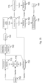
- a director 700 may have created an omnidirectional video, e.g., with a resolution of 16K, and encoded said video, e.g., using VP9, while encoding the audio, e.g., using the so-termed Opus codec. Both the encoded video and audio may be packaged in a WebM container.
- the director may identify a region of interest 715, and may decide to draw the attention of users, e.g., the viewers of the video, by magnifying this region.
- the director 700 may decide to employ a magnification transformation 720 by which the original video image is stretched in a spherical manner, e.g., such that the center of the region of interest 715 is magnified four times, with the magnification linearly decreasing towards the edges of the region of interest 715.
- the radius of the apparent magnification sphere may be defined as 10 spherical degrees.
- the director may decide to insert the following JSON metadata into each frame of the video, e.g., using an authoring tool:
- the OVV 760 may first generate a regular sphere mesh, e.g., by dividing the longitude in 40 equally-sized partitions, and likewise for the latitude. As a result, a sphere mesh may be obtained which may comprise 1600 vertices. During playback, the OVV 760 may encounter the director's metadata, and modify the geometry of the sphere mesh 775 to realize the requested deformation, for example as follows.
- the viewing position of the user e.g., represented by a virtual camera in the viewing scene 770, 780
- the deformation may be applied to all vertices which satisfy the following property: the distance of a vertex to the center of the magnification location (e.g. the location (0°,10°) in this embodiment) may span at most 10° of the field of view.
- the vertex v c which is the vector at the center of the magnification location.
- An arbitrary vertex v i will then be transformed if and only if: cos ⁇ 1 v c ⁇ v i v c v i ⁇ 10 ⁇
- the set SOL may have either one or two elements, given that all vertices not in range of the sphere were filtered out beforehand. Therefore, the line intersects S at least one time, and at most two times.
- v i ′ min v , where v ⁇ SOL
- a magnifying video sphere 785 may be obtained.
- the current video frame may be selected as the texture for the magnifying video sphere 785.
- the OVV 760 may send the viewing scene 780 to the rendering pipeline of the rendering system, and the scene may be rendered as usual, resulting in a rendered processed omnidirectional video 790 which may be displayed to the user 795.
- the region of interest may appear as if it has been zoomed-in since it is closer to the user's location in the virtual environment.
- this technique is applicable to both monoscopic (e.g. a television screen) and stereoscopic viewing (e.g. a VR-headset).
- monoscopic e.g. a television screen
- stereoscopic viewing e.g. a VR-headset
- the mesh of the viewing sphere has been adjusted, the stereoscopic images seen by the user may be different for each eye.
- This may create a 3D-effect, which may allow the user to look to the sides of the zoomed area.
- This 3D effect may also be used for theatrical reasons. For example, when zooming in on a rectangular object, a rectangular displacement may be used to enhance the depth perception of said object.
- a director 700 may have created an omnidirectional video, e.g., with the following properties: a resolution of 16K, with the spherical images being encoded using an equirectangular projection, with the video stream being encoded using VP9, with the audio stream being encoded with the Opus codec, and the media streams being packaged in a WebM container.
- the director 700 may identify a region of interest 715, and decide to draw the attention viewers by magnifying this region. For this purpose, the director may decide to use a transformation 720 where the original image is stretched such that the center of the region of interest is magnified four times, where the magnification linearly decreases towards the edges.
- the size of the apparent magnification sphere may be defined as 10 (spherical) degrees.
- the director 700 may provide the unprocessed omnidirectional video file 710 to a magnification transformation applicator (MTA) 730 program, which may apply the magnification transformation 720 to the omnidirectional video by processing its image data.
- MTA magnification transformation applicator
- the 'FFmpeg' program may be used, which may be configured to use a magnification transformation filter which applies the following magnification transformation 720 to the image data of each video frame.
- Tait-Bryan angles e.g. Pitch and Yaw
- yaw ( ⁇ ) denotes a rotation in the xy-plane
- pitch a rotation in the z-plane
- v p ′ p ⁇ ⁇ 1 v p
- the MTA program 730 may apply an interpolation filter (for example: bilinear, trilinear or anisotropic interpolation) in order to fill any 'gaps' resulting from the discrete application of this transformation.
- an interpolation filter for example: bilinear, trilinear or anisotropic interpolation
- this may provide an arbitrary level of detail for said filters. Note that this embodiment demonstrates only one example of a transformation function. Any function f : R 2 ⁇ R 2 may suffice in this regard.
- the director may have obtained a processed omnidirectional video file 742 which comprises the zoomed region 745.
- the processed omnidirectional video file 742 may now be distributed to a rendering system of a user 795, e.g., via a medium 750 such as the internet.
- the play-out of such a video file may then be conventional, e.g., using an Omnidirectional Video Viewer (OVV) program 762.
- OOV Omnidirectional Video Viewer
- the processed omnidirectional video file 742 may be indistinguishable from a regular unprocessed omnidirectional video from the perspective of the OVV 762.
- the OVV 762 may play-out said video without additional configuration.
- the transformation mt 720 is not limited for application by the director.
- the magnification transformation 720 may also be applied:
- a transformation may be specified at multiple different locations in the process, e.g., by the end-user, by the party providing the video (e.g. in a streaming situation) or by a third party (system). Examples of the latter include:
- a director 700 may have created an omnidirectional video, e.g., with the following properties: a resolution of 16K, with the spherical images being encoded using an equirectangular projection, with the video stream being encoded using VP9, with the audio stream being encoded with the Opus codec, and the media streams being packaged in a WebM container
- a user may receive the WebM container file, e.g., via the Internet, and use an Omnidirectional Video Viewer (OVV) to play the file.
- the OVV may generate a virtual environment in which a virtual camera, representing the user's point of view, is placed at the origin of the 3D-space.
- a (hollow) sphere with radius r may be placed at the origin, e.g., with the vertices being placed at every 5° of longitude and latitude.
- the UV coordinates may be specified such that the resulting texture map performs an inverse equirectangular projection on an input texture.
- the OVV may use a decoder to obtain the video and audio from the WebM container.
- the audio may be decoded and played-out in a conventional manner.
- the video may be decoded as well.
- the OVV may use the decoded frame as a texture of the surrounding sphere.
- the user may view the video, e.g., using a head-mounted display (HMD), which allows him/her to look around inside the sphere, resulting in a 360° view of the omnidirectional video.
- HMD head-mounted display
- the user may desire to zoom the video.
- the OVV may implement zooming functionality as follows.
- a disc-shaped zoom is provided, similar to Fig. 9 .
- any other shape may be used.
- the resulting scene may be rendered and displayed to the user.
- Zooming may be implemented by adjusting the projection of the image data onto the virtual body.
- UV coordinates of the virtual body, on which an omnidirectional video is rendered are displaced.
- the applicability/accuracy of this method may be restricted by the amount of vertices of the virtual body.
- a UV-map may be generated for the virtual body, being here a sphere, e.g., a 'viewing sphere', with radius 1.
- the sphere may be split into two halves.
- the top hemisphere may be projected orthogonally along the z-axis onto the left half of the UV-space, whereas the bottom hemisphere may be projected orthogonally along the z-axis onto the right half of the UV-space.
- the zooming object definition may comprise the following properties:
- a new virtual position of each vertex may be calculated with respect to the center taking into account the magnification factor.
- the vertex v z ' may be calculated and normalized. This vertex v z ' may be used as an image to calculate the new UV coordinates for v c , used to achieve the magnification effect:
- v z ′ v c + v z ⁇ M ⁇ 1 v c + v z ⁇ M ⁇ 1
- UV coordinates (u', v') may be assigned to the original. It will be appreciated that this operation, as well as all aforementioned calculations, may be performed in the vertex shader, e.g., of a Graphics Processing Unit (GPU).
- GPU Graphics Processing Unit
- the techniques described in this specification may be used to provide multiple zoomed portions, e.g., a partitioning, which may have different zoom levels.
- the zoom level e.g., the magnification ratio defined by magnified size original size
- the zoom level may be expressed by any value in the range 0 ⁇ ⁇ R .
- the techniques described in this specification are also applicable to live (adaptive) streaming, where one or more layers of a 360° video content are being transmitted as soon as they are captured.
- the location of the magnification object may be static with respect to the field of view of the user, e.g., in the center of the view, thereby drawing the attention of the user, or in another location, e.g., allowing the user to look straight past the magnification object.
- the object's location may also be dynamic with respect to the field of view of the user.
- the location may be controlled by the director, e.g., by providing signaling over a network interface, or by providing signaling in the media file.
- the location may also be controlled by the user, e.g., by using VR motion (tracking) controllers, or by using gaze detection to detect the user's gaze and establishing the location of the magnification object to slowly follow the user's gaze.
- the zooming configuration e.g., the zoom level or the size of the zoomed region, may be purposefully restricted to reduce expected levels of nausea by ensuring that the user is always able to have a frame of reference with respect to the video, e.g., by ensuring that a fraction of the view always contains non-zoomed content.
- the magnification level may be dynamically controlled, e.g., by the director or by user, e.g., using VR motion (tracking) controllers or by (gradually) adapting the zooming level when the user gazes at the magnification object and (gradually) resetting the zooming level when the user looks elsewhere.
- the zooming level may also be controlled based on where in the magnification object the user's gaze is pointed at, e.g., 1x magnification at the edges, 10x magnification in the center, with an easing function, e.g., using the examples shown in [4] to provide fluid interpolation.
- the magnification object may have different shapes. Depending on what is desired by the director or user, the magnification object may take the shape of, e.g., a rounded rectangle, torus, a teapot, and convex and/or concave meshes. In this respect, it is noted that the shape of the magnification object does not have to be defined as a three-dimensional object but may also rather have a two-dimensional shape.
- a different part of the video may also be magnified instead, resulting in a potentially non-Euclidian viewing experience.
- Another comparison is that of a Heads-Up-Display or floating user interface, providing a specific view on the video. Multiple zoomed views may be provided at the same time.
- a virtual lens may be used to simultaneously show the current view and the point-of-interest.
- the required bandwidth for providing the magnified content can be greatly reduced.
- matching the part of the 360° video currently magnified e.g. by inverse projection, it may be detected which tiles of the high-resolution content match this part of the 360° video.
- the rendering system may only fetch those tiles required to render the magnified part.
- the director may influence, e.g., by signaling, whether magnification is enabled, whether multiple magnification objects are used, adjust the magnification level, adjust the location of the magnification, adjust the shape of the magnification, and change the shape of the distortions introduced by the magnification object.
- the tracking of physical objects in the physical real-life environment may be used to determine the location of a magnification lens.
- the user may manipulate the shape and zoom-level of the magnification object using gestures, e.g., as may be detected by gesture detection, or using controllers including but not limited a keyboard, mouse, 6-DOF tracking controllers such as a WiiMote, a HTC Vive controller, a Oculus Rift controller, etc.
- gestures e.g., as may be detected by gesture detection, or using controllers including but not limited a keyboard, mouse, 6-DOF tracking controllers such as a WiiMote, a HTC Vive controller, a Oculus Rift controller, etc.
- the omnidirectional image or video may be obtained in real-time by a camera worn by the user, e.g., comprised in or mounted to a HMD.
- the image data may represent the user's current physical real-world environment.
- the magnification may be performed by the server of the content, e.g., the sender system, instead of by the client, e.g., the rendering system. Some of the complexity of the client implementation may thereby be moved to the server implementation.
- the server may render a regular equirectangular 360° video, which includes a magnified part.
- the client may then simply use the regular 360° video rendering method to display the video comprising the magnified part.
- Server-side rendering may be used, where all 3D graphics are rendered by the server.
- the zooming functionality described in this specification, or a subset thereof, may be provided in the form of an extension to MPEG-OMAF.
- the HTTP adaptive streaming standard MPEG-DASH supports the definition of additional properties for signaling, and may be used to establish any of the signalling described in this specification.
- the magnification object may also be established by a plugin for a VR or gaming environment, such as but not limited to A-frame, Unity or Unreal Engine.
- the zooming when invoked, may be introduced gradually ever time, e.g., by animation rather than in a binary manner.
- the zoomed-in view may be established over the course of several tens or hundreds of milliseconds or even seconds.
- Such animation may also be used when disabling the zooming.
- zooming out may allow the user to view what is happening behind the car.
- the car in this example can be essentially replaced by any moving object (e.g. a plane, bicycle, stone, rocket, bullet, ant).
- a user may be watching an omnidirectional movie of a whale basin. Slowly, the whale moves in front of the camera, obscuring most of the view. The user may zoom out to improve his/her view of the surroundings, and to be able to observe the whole animal.
- the user may watch a reenactment of a historical battle.
- the viewpoint is set on a hill such that both armies can be viewed at the same time.
- the director decides to zoom out in the center of the view, and zoom in on both sides of the view, where the center of the view allows viewing the complete battlefield, whereas the sides of the view now focus on the front unit of each army.
- any of the methods described in this specification may be implemented on a computer as a computer implemented method, as dedicated hardware, or as a combination of both.
- Instructions for the computer e.g., executable code
- the executable code may be stored in a transitory or non-transitory manner. Examples of computer readable mediums include memory devices, optical storage devices, integrated circuits, servers, online software, etc.
- Fig. 17 is a block diagram illustrating an exemplary data processing system that may be used in the embodiments described in this specification.
- Such data processing systems include data processing entities described in this specification, including but not limited to the sender system and the rendering system.
- the data processing system 1000 may include at least one processor 1002 coupled to memory elements 1004 through a system bus 1006. As such, the data processing system may store program code within memory elements 1004. Further, processor 1002 may execute the program code accessed from memory elements 1004 via system bus 1006. In one aspect, data processing system may be implemented as a computer that is suitable for storing and/or executing program code. It should be appreciated, however, that data processing system 1000 may be implemented in the form of any system including a processor and memory that is capable of performing the functions described within this specification.
- Memory elements 1004 may include one or more physical memory devices such as, for example, local memory 1008 and one or more bulk storage devices 1010.
- Local memory may refer to random access memory or other non-persistent memory device(s) generally used during actual execution of the program code.
- a bulk storage device may be implemented as a hard drive, solid state disk or other persistent data storage device.
- the processing system 1000 may also include one or more cache memories (not shown) that provide temporary storage of at least some program code in order to reduce the number of times program code must be retrieved from bulk storage device 1010 during execution.
- I/O devices depicted as input device 1012 and output device 1014 optionally can be coupled to the data processing system.
- input devices may include, but are not limited to, for example, a microphone, a keyboard, a pointing device such as a mouse, a game controller, a Bluetooth controller, a VR controller, and a gesture based input device, or the like.
- output devices may include, but are not limited to, for example, a monitor or display, speakers, or the like.
- Input device and/or output device may be coupled to data processing system either directly or through intervening I/O controllers.
- a network adapter 1016 may also be coupled to data processing system to enable it to become coupled to other systems, computer systems, remote network devices, and/or remote storage devices through intervening private or public networks.
- the network adapter may comprise a data receiver for receiving data that is transmitted by said systems, devices and/or networks to said data and a data transmitter for transmitting data to said systems, devices and/or networks.
- Modems, cable modems, and Ethernet cards are examples of different types of network adapter that may be used with data processing system 1000.
- memory elements 1004 may store an application 1018. It should be appreciated that data processing system 1000 may further execute an operating system (not shown) that can facilitate execution of the application.
- the application being implemented in the form of executable program code, can be executed by data processing system 1000, e.g., by processor 1002. Responsive to executing the application, the data processing system may be configured to perform one or more operations to be described herein in further detail.
- data processing system 1000 may represent the sender system.
- application 1018 may represent an application that, when executed, configures data processing system 1000 to perform the functions described herein with reference to the sender system.
- data processing system 1000 may represent the rendering system.
- application 1018 may represent an application that, when executed, configures data processing system 1000 to perform the functions described herein with reference to the rendering system.
- any reference signs placed between parentheses shall not be construed as limiting the claim.
- Use of the verb "comprise” and its conjugations does not exclude the presence of elements or steps other than those stated in a claim.
- the article "a” or “an” preceding an element does not exclude the presence of a plurality of such elements.
- the invention may be implemented by means of hardware comprising several distinct elements, and by means of a suitably programmed computer. In the device claim enumerating several means, several of these means may be embodied by one and the same item of hardware. The mere fact that certain measures are recited in mutually different dependent claims does not indicate that a combination of these measures cannot be used to advantage.
Landscapes
- Engineering & Computer Science (AREA)
- Multimedia (AREA)
- Physics & Mathematics (AREA)
- General Physics & Mathematics (AREA)
- Theoretical Computer Science (AREA)
- Human Computer Interaction (AREA)
- Biophysics (AREA)
- Cardiology (AREA)
- General Health & Medical Sciences (AREA)
- Heart & Thoracic Surgery (AREA)
- Life Sciences & Earth Sciences (AREA)
- Health & Medical Sciences (AREA)
- Controls And Circuits For Display Device (AREA)
- Processing Or Creating Images (AREA)
Claims (16)
- Procédé de zoom d'une vidéo omnidirectionnelle qui est représentée par des données d'image et qui peut être visualisée en réalité virtuelle ou augmentée sur la base des données d'image i) projetées sur un corps virtuel dans un environnement virtuel et ii) rendues à partir d'un point de vue à l'intérieur ou en face du corps virtuel, pour ainsi obtenir une image rendue à afficher, le procédé comprenant :- l'obtention d'une entrée d'utilisateur comprenant l'obtention d'une mesure à partir d'un système de suivi de tête qui indique un mouvement de translation et/ou de rotation de la tête d'un utilisateur ;- la détermination d'une région à zoomer dans la vidéo omnidirectionnelle ;- la sélection de la région à zoomer ou l'ajustement d'un paramètre dudit zoom, sur la base de l'entrée d'utilisateur ; et- la fourniture dans l'image rendue :d'une partie zoomée qui fournit une vue zoomée de la région, dans lequel la taille de la partie zoomée est inversement proportionnelle à l'amplitude de mouvement de la tête ou à l'accélération du mouvement de la tête de l'utilisateur, etsimultanément avec la partie zoomée, d'une partie non zoomée qui fournit une vue non zoomée par défaut ou une vue ayant un facteur de zoom inférieur à la vue zoomée de la partie zoomée, dans lequel la partie zoomée est une partie centrale de l'image rendue, et dans lequel la partie non zoomée est une périphérie de la partie centrale dans l'image rendue.
- Procédé selon la revendication 1, dans lequel la fourniture de la vue zoomée de la région comprend le traitement des données d'image avant que les données d'image ne soient projetées sur le corps virtuel ou l'ajustement de ladite projection des données d'image, pour établir la vue zoomée de la région sur une surface du corps virtuel.
- Procédé selon la revendication 1, dans lequel la fourniture de la vue zoomée de la région comprend la déformation ou l'adaptation du corps virtuel pour positionner une partie du corps virtuel plus près ou plus loin du point de vue.
- Procédé selon la revendication 3, dans lequel ladite déformation comprend l'enfoncement d'une surface du corps virtuel vers ou à l'opposé du point de vue.
- Procédé selon la revendication 1, dans lequel la fourniture de la vue zoomée de la région comprend la redirection de la lumière dans l'environnement virtuel pour établir la vue zoomée de la région pendant le rendu.
- Procédé selon la revendication 5, dans lequel la redirection de la lumière comprend la fourniture d'un objet de redirection de lumière dans l'environnement virtuel, tel qu'une lentille.
- Procédé selon l'une quelconque des revendications précédentes, dans lequel l'obtention de l'entrée d'utilisateur comprend la détection d'un regard d'un utilisateur pour identifier un point de regard de l'utilisateur par rapport à l'image rendue.
- Procédé selon l'une quelconque des revendications précédentes, dans lequel les données d'image sont obtenues par une vidéo en couches comprenant une couche de base et une couche de zoom, dans lequel la fourniture de la partie zoomée de l'image rendue comprend la sélection de données d'image à partir de la couche de zoom et dans lequel la fourniture de la partie non zoomée comprend la sélection de données d'image à partir de la couche de base.
- Support transitoire ou non transitoire lisible par ordinateur comprenant un programme informatique, le programme informatique comprenant des instructions pour amener un système de processeur à réaliser le procédé selon l'une quelconque des revendications 1 à 8.
- Système de rendu (200) configuré pour rendre un environnement virtuel en réalité virtuelle ou augmentée, dans lequel le système de rendu comprend :- une interface de données d'image (210) pour obtenir des données d'image représentant une vidéo omnidirectionnelle ;- un processeur (220) configuré pour permettre la visualisation de la vidéo omnidirectionnelle dans l'environnement virtuel en i) projetant les données d'image sur un corps virtuel et ii) rendant l'environnement virtuel à partir d'un point de vue à l'intérieur ou en face du corps virtuel, pour ainsi obtenir une image rendue ; et- une interface d'affichage (230) pour fournir l'image rendue à un dispositif d'affichage : dans lequel le processeur est en outre configuré pour:- obtenir une entrée d'utilisateur comprenant l'obtention d'une mesure à partir d'un système de suivi de tête qui indique un mouvement de translation et/ou de rotation de la tête d'un utilisateur (250) ;- déterminer une région à zoomer dans la vidéo omnidirectionnelle ;- sélectionner la région à zoomer ou ajuster un paramètre dudit zoom, sur la base de l'entrée d'utilisateur ; et- fournir dans l'image rendue :une partie zoomée qui fournit une vue zoomée de la région, dans lequel la taille de la partie zoomée est inversement proportionnelle à l'amplitude de mouvement de la tête ou à l'accélération du mouvement de la tête de l'utilisateur, etsimultanément avec la partie zoomée, une partie non zoomée qui fournit une vue non zoomée par défaut ou une vue ayant un facteur de zoom inférieur à la vue zoomée de la partie zoomée, dans lequel la partie zoomée est une partie centrale de l'image rendue, et dans lequel la partie non zoomée est une périphérie de la partie centrale dans l'image rendue.
- Système de rendu selon la revendication 10, dans lequel l'interface de données d'image est une interface réseau configurée pour recevoir les données d'image via un réseau d'un système émetteur, et dans lequel le processeur est configuré pour fournir la vue zoomée de la région en signalant au système émetteur via une interface de communication de traiter les données d'image de façon à établir la vue zoomée de la région dans les données d'image avant que les données d'image ne soient transmises au système de rendu.
- Système de rendu selon la revendication 10 ou 11, dans lequel le processeur est configuré pour fournir la vue zoomée de la région en traitant les données d'image avant que les données d'image ne soient projetées sur le corps virtuel ou en ajustant ladite projection des données d'image, pour établir la vue zoomée de la région sur une surface du corps virtuel.
- Système de rendu selon la revendication 10 ou 11, dans lequel le processeur est configuré pour fournir la vue zoomée de la région en déformant ou en adaptant le corps virtuel pour positionner une partie du corps virtuel plus près ou plus loin du point de vue.
- Système de rendu selon la revendication 10 ou 11, dans lequel le processeur est configuré pour fournir la vue zoomée de la région en redirigeant la lumière dans l'environnement virtuel pour établir la vue zoomée de la région pendant le rendu.
- Système de rendu selon l'une quelconque des revendications 10 à 14, dans lequel les données d'image sont obtenues par une vidéo en couches comprenant une couche de base et une couche de zoom, dans lequel le processeur est configuré pour fournir la partie zoomée de l'image rendue en sélectionnant des données d'image à partir de la couche de zoom et pour fournir la partie non zoomée en sélectionnant des données d'image à partir de la couche de base.
- Système émetteur (100) pour fournir des données d'image (112) d'une vidéo omnidirectionnelle à un système de rendu (200) qui est configuré pour permettre la visualisation de la vidéo omnidirectionnelle en réalité virtuelle ou augmentée en i) projetant les données d'image dans un environnement virtuel sur un corps virtuel et ii) rendant l'environnement virtuel à partir d'un point de vue à l'intérieur ou en face du corps virtuel, pour ainsi obtenir une image rendue, dans lequel le système émetteur comprend :- une interface réseau (110) pour transmettre les données d'image via un réseau (150) au système de rendu ; et- un processeur (120) configuré pour :- obtenir une entrée d'utilisateur comprenant l'obtention d'une mesure à partir d'un système de suivi de tête qui indique un mouvement de translation et/ou de rotation de la tête d'un utilisateur (250) ;- déterminer une région à zoomer dans la vidéo omnidirectionnelle ;- sélectionner la région à zoomer ou ajuster un paramètre dudit zoom, sur la base de l'entrée d'utilisateur, dans lequel la taille de la région zoomée est inversement proportionnelle à l'amplitude de mouvement de la tête ou à l'accélération du mouvement de la tête de l'utilisateur ; et- permettre le zoom de la vidéo omnidirectionnelle au sein de l'environnement virtuel en :- utilisant l'interface réseau, signalant au système de rendu de fournir une vue zoomée de la région dans l'image rendue, pour ainsi fournir une partie zoomée et une partie non zoomée de l'image rendue, dans lequel la partie non zoomée fournit une vue non zoomée par défaut ou une vue ayant un facteur de zoom inférieur à la vue zoomée de la partie zoomée, et dans lequel la partie zoomée est une partie centrale de l'image rendue, et dans lequel la partie non zoomée est une périphérie de la partie centrale de l'image rendue ; ou- traitant les données d'image pour établir la vue zoomée de la région dans les données d'image avant que les données d'image ne soient transmises au système de rendu, pour ainsi fournir une partie zoomée et une partie non zoomée des données d'image, dans lequel la partie non zoomée fournit une vue non zoomée par défaut ou une vue ayant un facteur de zoom inférieur à la vue zoomée de la partie zoomée, et dans lequel la partie zoomée est une partie centrale de l'image rendue, et dans lequel la partie non zoomée est une périphérie de la partie centrale dans l'image rendue.
Applications Claiming Priority (2)
| Application Number | Priority Date | Filing Date | Title |
|---|---|---|---|
| EP17188233 | 2017-08-29 | ||
| PCT/EP2018/073169 WO2019043025A1 (fr) | 2017-08-29 | 2018-08-29 | Zoomage d'une image ou d'une vidéo omnidirectionnelle |
Publications (2)
| Publication Number | Publication Date |
|---|---|
| EP3676794A1 EP3676794A1 (fr) | 2020-07-08 |
| EP3676794B1 true EP3676794B1 (fr) | 2025-04-23 |
Family
ID=59745231
Family Applications (1)
| Application Number | Title | Priority Date | Filing Date |
|---|---|---|---|
| EP18756474.5A Active EP3676794B1 (fr) | 2017-08-29 | 2018-08-29 | Zoom sur une image ou une vidéo omnidirectionnelle |
Country Status (2)
| Country | Link |
|---|---|
| EP (1) | EP3676794B1 (fr) |
| WO (1) | WO2019043025A1 (fr) |
Cited By (1)
| Publication number | Priority date | Publication date | Assignee | Title |
|---|---|---|---|---|
| EP4517519A4 (fr) * | 2022-04-29 | 2026-01-07 | Beijing Zitiao Network Technology Co Ltd | Procédé et appareil de rendu d'écran fractionné, dispositif et support de stockage |
Families Citing this family (11)
| Publication number | Priority date | Publication date | Assignee | Title |
|---|---|---|---|---|
| JP7301567B2 (ja) | 2019-03-20 | 2023-07-03 | 任天堂株式会社 | 画像表示システム、画像表示プログラム、画像表示装置、および画像表示方法 |
| US20230005101A1 (en) * | 2019-12-19 | 2023-01-05 | Sony Group Corporation | Information processing apparatus, information processing method, and recording medium |
| WO2021130355A1 (fr) | 2019-12-24 | 2021-07-01 | Koninklijke Kpn N.V. | Dispositif de traitement vidéo et fichier manifeste pour diffusion vidéo en continu |
| US20230027801A1 (en) * | 2020-01-06 | 2023-01-26 | The Johns Hopkins University | Overlaying augmented reality (ar) content within an ar headset coupled to a magnifying loupe |
| US12309434B2 (en) | 2020-10-01 | 2025-05-20 | Koninklijke Kpn N.V. | Streaming panoramic video of a scene from multiple viewpoints |
| CN118318453A (zh) * | 2021-12-02 | 2024-07-09 | 皇家Kpn公司 | 渲染包括对象的3d场景 |
| WO2023232612A1 (fr) | 2022-06-01 | 2023-12-07 | Koninklijke Philips N.V. | Guidage pour interventions médicales |
| EP4286991A1 (fr) | 2022-06-01 | 2023-12-06 | Koninklijke Philips N.V. | Guidage pour interventions médicales |
| US20240139462A1 (en) * | 2022-10-28 | 2024-05-02 | Rovi Guides, Inc. | Methods for cybersickness mitigation in virtual reality experiences |
| US12072501B1 (en) | 2023-02-14 | 2024-08-27 | Google Llc | Decreasing size of user interface element in display of head-mounted device |
| CN117991962B (zh) * | 2024-04-03 | 2024-06-18 | 山东捷瑞数字科技股份有限公司 | 一种基于云平台的限制图像缩放和拖拽方法 |
-
2018
- 2018-08-29 WO PCT/EP2018/073169 patent/WO2019043025A1/fr not_active Ceased
- 2018-08-29 EP EP18756474.5A patent/EP3676794B1/fr active Active
Cited By (1)
| Publication number | Priority date | Publication date | Assignee | Title |
|---|---|---|---|---|
| EP4517519A4 (fr) * | 2022-04-29 | 2026-01-07 | Beijing Zitiao Network Technology Co Ltd | Procédé et appareil de rendu d'écran fractionné, dispositif et support de stockage |
Also Published As
| Publication number | Publication date |
|---|---|
| EP3676794A1 (fr) | 2020-07-08 |
| WO2019043025A1 (fr) | 2019-03-07 |
Similar Documents
| Publication | Publication Date | Title |
|---|---|---|
| EP3676794B1 (fr) | Zoom sur une image ou une vidéo omnidirectionnelle | |
| US10497399B2 (en) | Biometric feedback in production and playback of video content | |
| CN107590771B (zh) | 具有用于在建模3d空间中投影观看的选项的2d视频 | |
| US10600245B1 (en) | Navigating a virtual environment of a media content item | |
| KR102052567B1 (ko) | 가상의 3차원 비디오 생성 및 관리 시스템 및 방법 | |
| US11099392B2 (en) | Stabilized and tracked enhanced reality images | |
| US12341941B2 (en) | Methods, systems, and media for rendering immersive video content with foveated meshes | |
| CN107636534A (zh) | 一般球面捕获方法 | |
| WO2019002559A1 (fr) | Partage d'écran pour affichage dans une réalité virtuelle | |
| KR20200079162A (ko) | 실감형 콘텐츠 제공 장치 및 방법 | |
| JP7447266B2 (ja) | ボリュメトリック画像データに関するビューの符号化及び復号 | |
| US12432329B2 (en) | Methods, systems, and media for generating and rendering immersive video content | |
| US11187895B2 (en) | Content generation apparatus and method | |
| TWI846808B (zh) | 表示場景之影像信號 | |
| CN113286138A (zh) | 一种全景视频显示方法及显示设备 | |
| US20190295324A1 (en) | Optimized content sharing interaction using a mixed reality environment | |
| GB2548080A (en) | A method for image transformation | |
| EP3330839A1 (fr) | Procédé et dispositif permettant d'adapter un contenu immersif au champ de vision d'un utilisateur | |
| JP2019121072A (ja) | 3dcg空間の鑑賞条件連動システム、方法、およびプログラム |
Legal Events
| Date | Code | Title | Description |
|---|---|---|---|
| STAA | Information on the status of an ep patent application or granted ep patent |
Free format text: STATUS: UNKNOWN |
|
| STAA | Information on the status of an ep patent application or granted ep patent |
Free format text: STATUS: THE INTERNATIONAL PUBLICATION HAS BEEN MADE |
|
| PUAI | Public reference made under article 153(3) epc to a published international application that has entered the european phase |
Free format text: ORIGINAL CODE: 0009012 |
|
| STAA | Information on the status of an ep patent application or granted ep patent |
Free format text: STATUS: REQUEST FOR EXAMINATION WAS MADE |
|
| 17P | Request for examination filed |
Effective date: 20200330 |
|
| AK | Designated contracting states |
Kind code of ref document: A1 Designated state(s): AL AT BE BG CH CY CZ DE DK EE ES FI FR GB GR HR HU IE IS IT LI LT LU LV MC MK MT NL NO PL PT RO RS SE SI SK SM TR |
|
| AX | Request for extension of the european patent |
Extension state: BA ME |
|
| DAV | Request for validation of the european patent (deleted) | ||
| DAX | Request for extension of the european patent (deleted) | ||
| STAA | Information on the status of an ep patent application or granted ep patent |
Free format text: STATUS: EXAMINATION IS IN PROGRESS |
|
| 17Q | First examination report despatched |
Effective date: 20220302 |
|
| P01 | Opt-out of the competence of the unified patent court (upc) registered |
Effective date: 20230517 |
|
| RIC1 | Information provided on ipc code assigned before grant |
Ipc: A63F 13/5255 20140101ALI20241214BHEP Ipc: A63F 13/212 20140101ALI20241214BHEP Ipc: H04N 13/30 20180101ALI20241214BHEP Ipc: G02B 27/01 20060101ALI20241214BHEP Ipc: G06T 3/40 20060101ALI20241214BHEP Ipc: G06T 3/04 20240101ALI20241214BHEP Ipc: G06T 3/00 20060101AFI20241214BHEP |
|
| GRAP | Despatch of communication of intention to grant a patent |
Free format text: ORIGINAL CODE: EPIDOSNIGR1 |
|
| STAA | Information on the status of an ep patent application or granted ep patent |
Free format text: STATUS: GRANT OF PATENT IS INTENDED |
|
| INTG | Intention to grant announced |
Effective date: 20250124 |
|
| GRAS | Grant fee paid |
Free format text: ORIGINAL CODE: EPIDOSNIGR3 |
|
| GRAA | (expected) grant |
Free format text: ORIGINAL CODE: 0009210 |
|
| STAA | Information on the status of an ep patent application or granted ep patent |
Free format text: STATUS: THE PATENT HAS BEEN GRANTED |
|
| AK | Designated contracting states |
Kind code of ref document: B1 Designated state(s): AL AT BE BG CH CY CZ DE DK EE ES FI FR GB GR HR HU IE IS IT LI LT LU LV MC MK MT NL NO PL PT RO RS SE SI SK SM TR |
|
| REG | Reference to a national code |
Ref country code: GB Ref legal event code: FG4D |
|
| REG | Reference to a national code |
Ref country code: CH Ref legal event code: EP |
|
| REG | Reference to a national code |
Ref country code: DE Ref legal event code: R096 Ref document number: 602018081320 Country of ref document: DE |
|
| REG | Reference to a national code |
Ref country code: IE Ref legal event code: FG4D |
|
| REG | Reference to a national code |
Ref country code: NL Ref legal event code: FP |
|
| PGFP | Annual fee paid to national office [announced via postgrant information from national office to epo] |
Ref country code: NL Payment date: 20250821 Year of fee payment: 8 |
|
| REG | Reference to a national code |
Ref country code: AT Ref legal event code: MK05 Ref document number: 1788526 Country of ref document: AT Kind code of ref document: T Effective date: 20250423 |
|
| PG25 | Lapsed in a contracting state [announced via postgrant information from national office to epo] |
Ref country code: FI Free format text: LAPSE BECAUSE OF FAILURE TO SUBMIT A TRANSLATION OF THE DESCRIPTION OR TO PAY THE FEE WITHIN THE PRESCRIBED TIME-LIMIT Effective date: 20250423 Ref country code: ES Free format text: LAPSE BECAUSE OF FAILURE TO SUBMIT A TRANSLATION OF THE DESCRIPTION OR TO PAY THE FEE WITHIN THE PRESCRIBED TIME-LIMIT Effective date: 20250423 Ref country code: PT Free format text: LAPSE BECAUSE OF FAILURE TO SUBMIT A TRANSLATION OF THE DESCRIPTION OR TO PAY THE FEE WITHIN THE PRESCRIBED TIME-LIMIT Effective date: 20250825 |
|
| PGFP | Annual fee paid to national office [announced via postgrant information from national office to epo] |
Ref country code: DE Payment date: 20250820 Year of fee payment: 8 |
|
| REG | Reference to a national code |
Ref country code: LT Ref legal event code: MG9D |
|
| PG25 | Lapsed in a contracting state [announced via postgrant information from national office to epo] |
Ref country code: GR Free format text: LAPSE BECAUSE OF FAILURE TO SUBMIT A TRANSLATION OF THE DESCRIPTION OR TO PAY THE FEE WITHIN THE PRESCRIBED TIME-LIMIT Effective date: 20250724 Ref country code: NO Free format text: LAPSE BECAUSE OF FAILURE TO SUBMIT A TRANSLATION OF THE DESCRIPTION OR TO PAY THE FEE WITHIN THE PRESCRIBED TIME-LIMIT Effective date: 20250723 |
|
| PG25 | Lapsed in a contracting state [announced via postgrant information from national office to epo] |
Ref country code: PL Free format text: LAPSE BECAUSE OF FAILURE TO SUBMIT A TRANSLATION OF THE DESCRIPTION OR TO PAY THE FEE WITHIN THE PRESCRIBED TIME-LIMIT Effective date: 20250423 |
|
| PG25 | Lapsed in a contracting state [announced via postgrant information from national office to epo] |
Ref country code: BG Free format text: LAPSE BECAUSE OF FAILURE TO SUBMIT A TRANSLATION OF THE DESCRIPTION OR TO PAY THE FEE WITHIN THE PRESCRIBED TIME-LIMIT Effective date: 20250423 |
|
| PGFP | Annual fee paid to national office [announced via postgrant information from national office to epo] |
Ref country code: GB Payment date: 20250820 Year of fee payment: 8 |
|
| PG25 | Lapsed in a contracting state [announced via postgrant information from national office to epo] |
Ref country code: HR Free format text: LAPSE BECAUSE OF FAILURE TO SUBMIT A TRANSLATION OF THE DESCRIPTION OR TO PAY THE FEE WITHIN THE PRESCRIBED TIME-LIMIT Effective date: 20250423 |
|
| PG25 | Lapsed in a contracting state [announced via postgrant information from national office to epo] |
Ref country code: AT Free format text: LAPSE BECAUSE OF FAILURE TO SUBMIT A TRANSLATION OF THE DESCRIPTION OR TO PAY THE FEE WITHIN THE PRESCRIBED TIME-LIMIT Effective date: 20250423 |
|
| PGFP | Annual fee paid to national office [announced via postgrant information from national office to epo] |
Ref country code: FR Payment date: 20250828 Year of fee payment: 8 |
|
| PG25 | Lapsed in a contracting state [announced via postgrant information from national office to epo] |
Ref country code: RS Free format text: LAPSE BECAUSE OF FAILURE TO SUBMIT A TRANSLATION OF THE DESCRIPTION OR TO PAY THE FEE WITHIN THE PRESCRIBED TIME-LIMIT Effective date: 20250723 |
|
| PG25 | Lapsed in a contracting state [announced via postgrant information from national office to epo] |
Ref country code: IS Free format text: LAPSE BECAUSE OF FAILURE TO SUBMIT A TRANSLATION OF THE DESCRIPTION OR TO PAY THE FEE WITHIN THE PRESCRIBED TIME-LIMIT Effective date: 20250823 |
|
| PG25 | Lapsed in a contracting state [announced via postgrant information from national office to epo] |
Ref country code: LV Free format text: LAPSE BECAUSE OF FAILURE TO SUBMIT A TRANSLATION OF THE DESCRIPTION OR TO PAY THE FEE WITHIN THE PRESCRIBED TIME-LIMIT Effective date: 20250423 |
|
| PG25 | Lapsed in a contracting state [announced via postgrant information from national office to epo] |
Ref country code: DK Free format text: LAPSE BECAUSE OF FAILURE TO SUBMIT A TRANSLATION OF THE DESCRIPTION OR TO PAY THE FEE WITHIN THE PRESCRIBED TIME-LIMIT Effective date: 20250423 Ref country code: SM Free format text: LAPSE BECAUSE OF FAILURE TO SUBMIT A TRANSLATION OF THE DESCRIPTION OR TO PAY THE FEE WITHIN THE PRESCRIBED TIME-LIMIT Effective date: 20250423 |
|
| PG25 | Lapsed in a contracting state [announced via postgrant information from national office to epo] |
Ref country code: CZ Free format text: LAPSE BECAUSE OF FAILURE TO SUBMIT A TRANSLATION OF THE DESCRIPTION OR TO PAY THE FEE WITHIN THE PRESCRIBED TIME-LIMIT Effective date: 20250423 |
|
| PG25 | Lapsed in a contracting state [announced via postgrant information from national office to epo] |
Ref country code: EE Free format text: LAPSE BECAUSE OF FAILURE TO SUBMIT A TRANSLATION OF THE DESCRIPTION OR TO PAY THE FEE WITHIN THE PRESCRIBED TIME-LIMIT Effective date: 20250423 |
|
| PG25 | Lapsed in a contracting state [announced via postgrant information from national office to epo] |
Ref country code: RO Free format text: LAPSE BECAUSE OF FAILURE TO SUBMIT A TRANSLATION OF THE DESCRIPTION OR TO PAY THE FEE WITHIN THE PRESCRIBED TIME-LIMIT Effective date: 20250423 Ref country code: SK Free format text: LAPSE BECAUSE OF FAILURE TO SUBMIT A TRANSLATION OF THE DESCRIPTION OR TO PAY THE FEE WITHIN THE PRESCRIBED TIME-LIMIT Effective date: 20250423 |
|
| PG25 | Lapsed in a contracting state [announced via postgrant information from national office to epo] |
Ref country code: IT Free format text: LAPSE BECAUSE OF FAILURE TO SUBMIT A TRANSLATION OF THE DESCRIPTION OR TO PAY THE FEE WITHIN THE PRESCRIBED TIME-LIMIT Effective date: 20250423 |