EP3676790B1 - System and method using probabilistic forecast for control of sewers - Google Patents
System and method using probabilistic forecast for control of sewers Download PDFInfo
- Publication number
- EP3676790B1 EP3676790B1 EP18878164.5A EP18878164A EP3676790B1 EP 3676790 B1 EP3676790 B1 EP 3676790B1 EP 18878164 A EP18878164 A EP 18878164A EP 3676790 B1 EP3676790 B1 EP 3676790B1
- Authority
- EP
- European Patent Office
- Prior art keywords
- flow
- sewer system
- fluid
- sewer
- condition attribute
- Prior art date
- Legal status (The legal status is an assumption and is not a legal conclusion. Google has not performed a legal analysis and makes no representation as to the accuracy of the status listed.)
- Active
Links
Images




Classifications
-
- E—FIXED CONSTRUCTIONS
- E03—WATER SUPPLY; SEWERAGE
- E03F—SEWERS; CESSPOOLS
- E03F3/00—Sewer pipe-line systems
- E03F3/02—Arrangement of sewer pipe-lines or pipe-line systems
-
- E—FIXED CONSTRUCTIONS
- E03—WATER SUPPLY; SEWERAGE
- E03F—SEWERS; CESSPOOLS
- E03F1/00—Methods, systems, or installations for draining-off sewage or storm water
-
- G—PHYSICS
- G01—MEASURING; TESTING
- G01F—MEASURING VOLUME, VOLUME FLOW, MASS FLOW OR LIQUID LEVEL; METERING BY VOLUME
- G01F1/00—Measuring the volume flow or mass flow of fluid or fluent solid material wherein the fluid passes through a meter in a continuous flow
-
- G—PHYSICS
- G05—CONTROLLING; REGULATING
- G05D—SYSTEMS FOR CONTROLLING OR REGULATING NON-ELECTRIC VARIABLES
- G05D7/00—Control of flow
- G05D7/06—Control of flow characterised by the use of electric means
- G05D7/0617—Control of flow characterised by the use of electric means specially adapted for fluid materials
-
- G—PHYSICS
- G06—COMPUTING OR CALCULATING; COUNTING
- G06F—ELECTRIC DIGITAL DATA PROCESSING
- G06F17/00—Digital computing or data processing equipment or methods, specially adapted for specific functions
- G06F17/10—Complex mathematical operations
- G06F17/18—Complex mathematical operations for evaluating statistical data, e.g. average values, frequency distributions, probability functions, regression analysis
-
- E—FIXED CONSTRUCTIONS
- E03—WATER SUPPLY; SEWERAGE
- E03F—SEWERS; CESSPOOLS
- E03F2201/00—Details, devices or methods not otherwise provided for
- E03F2201/20—Measuring flow in sewer systems
Definitions
- the present teachings generally relate to systems and methods relate to novel sewer systems. More particularly, the present teachings relate to novel systems and methods that use probabilistic forecast for agent-based control of sewer systems.
- a sewer system collects, transports, treats and/or dispenses fluid.
- the sewer system may include a network of interconnected trunk lines or pipes for directing fluid flow within the sewer system.
- sewer systems may include various components to treat and/or store the fluid. Managing complicated arrangements of these components poses unique challenges that remain unsolved. This problem is exacerbated when weather forecasts bring unpredictability to the loads placed on the sewer systems.
- JP3943370B discloses providing a maintenance system for sewerage facilities, which can remove a sediment in a sewer pipe without reliance on man power by opening/ closing a gate automatically or manually by remote control, eliminating the risks of the occurrence of a malodor and a toxic gas, the use of high pressure water and the like, and dispensing with the securement of a fluid to be used.
- This maintenance system for the sewerage facilities is equipped with: a means for securing held-back and collected water for removing the sediment by holding back water flows in the sewer pipes and of the sewerage facilities; and a means for discharging the water secured by opening a sluice gate.
- the means is a gate device which is installed in the sewer pipe.
- the maintenance system is also equipped with a means for preventing sewage from overflowing the sewer pipes and, by interlocking the sewage with a signal of a water gauge, while maintaining target water levels, brought about by the gate device, in the sewer pipes.
- US2014178211 provides a method for operating a wastewater pumping station of a wastewater pumping network.
- the pumping station includes a pump, that starts pumping if a level of a wastewater in a tank exceeds a first wastewater level, and the pump stops pumping if the level of the wastewater in the tank drops below a second level.
- the method includes determining a magnitude of a parameter (Psys, Q, n, ⁇ P, Pelectrical, cos ⁇ , I) expressing the load of the wastewater pumping network. If it is determined that the magnitude of the parameter has passed a specified threshold, the pump is activated to start pumping in an energy optimization mode.
- a control unit is also provided for the wastewater pumping station of the wastewater pumping network, and a system is provided for centrally controlling a plurality of pumps of wastewater pumping stations in a wastewater pumping network.
- the present teachings provide novel systems and methods using probabilistic forecast for agent-based control of sewer systems.
- probabilistic forecasts may inform on a variety of matters
- systems and methods of the present teachings use probabilistic weather forecasts for agent-based control.
- the present application provides a sewer system according to claim 8.
- one or more of the flow controllers of the present arrangements are programmed to provide instructions for modifying flow-rate of fluid exiting from the sewer system to enter a low-quality treatment scheme that is not part of the sewer system.
- the low-quality treatment scheme may be configured to provide partial treatment of fluid exiting from the sewer system. Partial treatment preferably excludes biological or contaminant treatment to maintain high flow-rates of fluid through a treatment scheme.
- one or more of the flow controllers are programmed to provide instructions for modifying flow-rate of fluid exiting from the sewer system to enter a high-quality treatment scheme that is not part of the sewer system.
- the high-quality treatment includes chemical, mechanical, and contaminant (including biological) treatment.
- the sewer system of the present arrangements preferably includes at least one storage chamber. Certain of these embodiments, however, may additionally include at least one treatment chamber, but it is not necessary.
- the flow condition attribute measuring device used for measuring the flow condition attribute value of fluid stored inside one of the storage chambers may be of the same type as the flow condition attribute measuring device used for measuring the flow condition attribute of fluid flowing inside the sewer system.
- the flow condition attribute measuring device used, in the present arrangements, for measuring the flow condition attribute value of fluid stored inside one of the storage chambers is of a different type than the flow condition attribute measuring device used for measuring the flow condition attribute value of fluid flowing inside the sewer system.
- one of the flow condition attribute measuring devices is a level meter that is configured to measure a height, or a level value of fluid stored inside one of the storage chambers.
- one of the flow condition attribute measuring devices is a flow-rate meter that is configured to measure a flow-rate of fluid flowing inside the sewer system.
- one or more the fluid flow controllers of the present arrangements is a proportional-integral-derivative controller that modifies a fluid pump rate of a pump that pumps fluid out of the sewer system and into a treatment scheme.
- Representative examples of the flow condition attribute include fluid flow-rate, fluid height, fluid volume, hydraulic capacity, time of fluid retention, storage capacity, and fluid quality.
- at least one of the flow condition attribute values is at least one value of a flow condition attribute chosen from a group comprising fluid flow-rate, fluid height, fluid volume, hydraulic capacity, time of fluid retention, storage capacity, and fluid quality.
- Fluid may include sewage (e.g., solids).
- One or more of the flow-modifying devices may include at least one member chosen from a group comprising fluid pump station, gate, inflatable dam, weir, pump and valve.
- One or more of the controllers preferably, modify flow exiting from the sewer system to be introduced into one or more treat schemes, at least one of which is chosen from a group comprising storage tank, fluid treatment plant, treatment chamber, holding pool, reservoir, ocean, and river.
- One or more flow controllers may be coupled to and operate in conjunction with a neural network.
- the application discloses a method according to claim 1 for managing a sewer system.
- One exemplar of such a method includes: (1) obtaining a probabilistic distribution forecast for a variable for each of multiple time intervals; (2) building for the variable, based upon the probabilistic distribution forecast, multiple time interval ensemble forecasts, each ensemble forecast for one of the multiple time intervals; (3) retrieving or developing a flow simulation to simulate flow of a fluid inside the sewer system; (4) initializing the flow simulation, by accounting for one or more flow condition attributes present inside the sewer system, to generate an initialized flow simulation; (5) running, based on an assumed value of one or more flow condition attributes present at a treatment scheme located outside the sewer system, the initialized flow simulation that uses each of the time interval ensemble forecasts to arrive at number of times one or more different potential outcomes are realized; (6) establishing, based on number of times one or more of the potential outcomes are realized, a cost function of realizing one or more potential outcomes of the sewer system; (7) establishing, based on one or more of the flow condition attributes in the sewer
- the above-mentioned "building” in (2) includes building a rainfall time interval ensemble forecast for multiple of the time intervals in series such that an average or median value of precipitation obtained from each of the time intervals substantially equals a value of the precipitation in corresponding ones of the time intervals of the rainfall probabilistic distribution forecast.
- the above-mentioned "initializing" in (4) includes using one or more primary flow condition attribute measuring devices, which measure one or more flow condition attributes inside the sewer system.
- the initializing in (4) preferably, includes using one or more measurements from a level meter, which measures a fluid level in a storage chamber inside the sewer systems, and also, preferably, includes one or more measurements from a flow-rate meter, which measures a flow-rate of a fluid exiting the sewer system and flowing into the treatment scheme.
- “Running” as described in (5), above, is carried out based on a current value of one or more flow condition attributes present at the treatment scheme located outside the sewer system.
- this running of initialized flow simulation includes using one or more measurements from a flow-rate meter, which measures flow-rate of a fluid that exits the sewer system and flows into the treatment scheme.
- the treatment scheme includes a low-quality treatment scheme.
- C storage Y / X + Y .
- "Y" represents number of times one of the potential outcomes is realized and "X” represents number of times another of the potential outcomes is realized, wherein one of the potential outcomes is different from another of the potential outcomes.
- the above-mentioned establishing described in (6) includes establishing the cost function of realizing one or more potential outcomes of the sewer system, and in the equation above, "Y” represents number of times one or more of the storage chambers overflows and "X" represents number of times one or more of the storage chambers does not overflow.
- Cst represents the cost of flow inside the sewer system
- Qst(t) represents a current flow condition attribute value associated with the treatment scheme located outside the sewer system
- Qmax represents a maximum flow condition attribute value associated with the treatment scheme
- ⁇ represents a minimum cost associated with the treatment scheme.
- the treatment scheme may include a low-quality treatment chamber for treating a fluid conveyed from the sewer system.
- Qst(t) specifically represents a current flow-rate through the high-rate treatment chamber
- Qmax specifically represents a maximum flow-rate through the high-rate treatment chamber
- ⁇ specifically represents the minimum cost associated with the high-rate treatment chamber.
- controlling preferably, includes using a proportional, integral, derivative controller.
- the controller controls operation of the flow-modifying device such that the flow-modifying device increases or decreases a flow-rate of the fluid exiting the sewer system and flowing into the treatment scheme.
- a specific implementation of "controlling” includes modifying, using a pump that receives instructions from the controller, a pumping rate of the fluid exiting the pump from the sewer system to the treatment scheme located outside the sewer system, and wherein the fluid includes sewage.
- the controlling includes increasing, prior to arrival of a storm, flow-rate of the fluid exiting the sewer system and flowing into the treatment scheme.
- FIG 1 shows a sewer management facility 10, according to one embodiment of the present arrangements and that includes a sewer system 15 that is coupled to a treatment scheme 25.
- Sewer system 15 includes a catchment area 12 and a storage chamber 14 fitted with an outlet 16 to discharge overflow of contents inside storage chamber.
- Treatment scheme 25 provides high-quality treatment and low-quality treatment.
- low-quality treatment the fluid is partially treated to produce water. Not in all embodiments, but typically low-quality treatment of the present teachings does not rely upon biological treatment, which may be time consuming. Rather, low-quality treatment implements mechanical and chemical treatment, which allow for high throughput of fluid treatment. In contrast, high-quality treatment is one that provides "full" treatment of water where all contaminants, including bacteria, are reduced below limits established by the Environmental Protection Agency. As such, high-quality treatment incorporates mechanical, chemical and biological treatment of sewage to produce water.
- Contents inside storage chamber 14 are conveyed through a high-quality treatment line 18 for high-quality treatment that is carried out using a primary chamber 22 and a secondary chamber 24.
- primary chamber 22 has a higher flow rate capacity of treatment than secondary chamber 24.
- contents of storage chamber 14 preferably, initially undergo solids removal and are subsequently treated for bacteria and nutrient compositions. Once the flow rate capacity of high-quality treatment reaches its maximum capacity, then through low-quality treatment line 20, contents of storage chamber 14 are preferably conveyed to low-quality treatment chamber 26.
- Primary chamber 22 is, preferably, configured to implement mechanical and chemical treatment and secondary chamber is preferably configured to implement contaminant removal. In certain embodiments, primary chamber of the present arrangements, however, also implements contaminant removal and as a result, a secondary chamber is not necessary.
- FIG. 2 shows a sewer management facility 40, according to one embodiment of the present arrangements and that is substantially similar to sewer management facility 10 shown in Figure 1 , except treatment scheme 55 of Figure 2 does not include a secondary chamber (like secondary chamber 24 of Figure 1 ) for high-quality treatment.
- sewer system 45 of Figure 2 that includes a catchment 42, a storage chamber 44, an outlet 46, a high-quality treatment line 48, a low-quality treatment line 50 are substantially similar to their counterparts described in connection with sewer system 15 of Figure 1 , i.e., catchment 12, a storage chamber 14, an outlet 16, a high-quality treatment line 18, a low-quality treatment line 20.
- primary chamber 52 may be substantially similar to primary chamber 22 of Figure 1 , except that primary chamber 52 may have a higher flow rate capacity of treatment than primary chamber 22. Further, once the flow rate capacity of high-quality treatment in primary chamber 52 reaches its maximum capacity, then through low-quality line 50, contents of storage chamber 44 are preferably conveyed to low-quality treatment chamber 56.
- catchment area is about 1 square mile
- storage chamber 44 has a capacity of about 500,000 gallons (about 2.000.000 litres)
- flow rate capacity of primary chamber 52 is a value that ranges from about 0 gallons per day to about 30 million gallons (about 120 million litres) per day
- that of secondary chamber is a value that ranges from about 0 gallons per day to about 50 million gallons (about 200 million litres) per day.
- a low-quality treatment chamber e.g. , chamber 26 of Figure 1 and chamber 56 of Figure 2
- a treatment scheme that relies on high flow rates of sewer treatment such as those realized when low-quality treatment is enabled, reduces the chances of overflow from an outlet of storage chamber (e.g ., outlet 16 of storage chamber 14 of Figure 1 and outlet 46 of storage chamber 44 of Figure 2 ).
- the present teachings recognize the merit of enabling low-quality treatment well in advance of the storm's arrival. For a "large” storm event, if the low-quality treatment is not enabled, then the present teachings recognize that the undesired outcome of "overflow” is realized. Further, if the storm event is deemed a "small” event, then it is unnecessary to expend the energy to enable and keep active low-quality treatment and, from one perspective, even more undesirable than that - discharge low-quality fluid into the environment.
- a “large storm event” may be more than or equal to 1 inch (about 2,5cm) of rainfall in an hour, and a “small storm event” may be less than or equal to 0.01 inches (about 0,25mm) of rainfall in an hour.
- the present teachings also recognize that overflow of untreated sewage is the most undesirable outcome and relative to the outcome of sewage overflow, low quality-treatment of sewage is a desirable outcome. Against this backdrop, it is important to analyze the desirability of these outcomes of "overflow of untreated sewage” or “no overflow of untreated sewage” in light of the amount of energy expended to avoid overflow. In certain circumstances, "overflow of untreated sewage” is an acceptable outcome when the energy enable low quality treatment is not being wasted. Thus, the present teachings recognize that, prior to arrival of a storm, a decision whether low-quality treatment is enabled should be made and this decision may be predicated on the size of the storm.
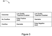
- Figure 3 shows a table that presents possible outcomes, i.e., "No Overflow” and “Overflow,” for both situations when “Low Quality Treatment [Is] Enabled” or when “Low Quality Treatment [Is] Disabled.”
- "No Overflow” e.g., sewage from outlet 16 of storage chamber 14 of Figure 1 does not overflow or sewage from outlet 46 of storage chamber 44 of Figure 2 does not overflow
- "No Overflow” is an undesirable outcome because unnecessary energy is expended to enable low quality treatment (when it is not required because the storm was not large enough in the first place to produce an overflow).
- the present invention recognizes, in some instances, the need to enable low quality treatment, or high flow rate treatment, well in advance of a storm's arrival.
- one consideration inquires into a period of time prior to a storm's arrival, should low quality treatment, or high flow rate treatment, be enabled.
- a decision to enable low-quality treatment, prior to arrival of a storm may depend on the forecast of the size of the storm. In other words, if the forecast is of a relatively large storm, then the low-quality treatment may be enabled relatively early compared to a situation where the forecast is for a relatively smaller-sized storm.
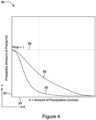
- Figure 4 shows a graphical representation of probabilistic forecasts 80, according to one embodiment of the present teachings.
- This representation shows values of a probability function of amount of precipitation greater than X (i.e., amount of precipitation) plotted along a Y-axis and values of X ( i.e., amount of precipitation in inches) plotted along an X-axis (which is perpendicular to the Y-axis).
- Probabilistic forecasts 80 shows a large rainfall curve 88 and a small rainfall curve 90 relative to a horizontal line that represents a condition when the probability function equals 1 (one).
- probabilistic forecasts provide insight into strength of a potential storm that will impact the capacity of a sewer management facility and accordingly, allows for effective management of sewage treatment.
- FIG. 5 shows a sewer management facility 100, according to one embodiment of the present arrangements.
- Sewer management facility 100 has certain components, i.e., catchment area 112, a storage chamber 114, an outlet 116, a high quality treatment line 118, and a low quality treatment line 120, that are substantially similar to their counterparts found in sewer management facility 45 of Figure 2 , i.e., catchment area 12, a storage chamber 14, an outlet 16, a high quality treatment line 18, and a low quality treatment line 20.
- Sewer management facility 100 further includes a level meter 130, a flow-modifying device 132, and a flow rate meter 134, each of which is communicatively coupled to a flow controller 128.
- flow controller receives information regarding level or height of sewage or fluid stored inside storage chamber 114 from level meter 130 and receives information regarding flow rate of sewage flowing (through flow rate meter 134) from flow rate meter 134. Measurement of flow rate from flow rate meter 134 also indicates the flow rate of sewage exiting from a sewer system 115 to a treatment scheme 125.
- treatment scheme 125 of the present arrangements is substantially similar to treatment scheme 25 of Figure 1 .
- treatment scheme 125 of the present arrangements is substantially similar to treatment scheme 55 of Figure 2 .
- each of high-quality treatment chamber 122 and low-quality treatment chamber 126 of Figure 5 are substantially similar to their counterparts of Figure 2 , i.e., high-quality treatment chamber 52 and low-quality treatment chamber 56 of Figure 2 , respectively.
- Figure 5 shows a single storage chamber, single ones of - storage chamber 114, level meter 130, flow-modifying device 132, flow rate meter 134, flow controller 128 and treatment scheme 125 or components therein
- the present arrangement are not so limited. Certain embodiments of the present arrangements include more than of - storage chamber 114, level meter 130, flow-modifying device 132, flow rate meter 134, flow controller 128 and treatment scheme 125 or components therein ( e.g ., primary chamber 122 and/or secondary chamber 126).
- FIG 6 shows a flow chart for a sewage management method 200, according to one embodiment of the present teachings.
- sewer management method 200 need not be implemented using any specific system or structure. However, implementing this method using sewer system 100 of Figure 5 represents a preferred embodiment of the present teachings.
- Sewer management method 200 preferably begins with a step 202 that involves obtaining a probabilistic distribution forecast for a variable for each of multiple time intervals.
- step 202 of the present teachings include obtaining from National Oceanic and Atmospheric Administration ("NOAA").
- NOAA National Oceanic and Atmospheric Administration
- each of Figures 7A-7D show a graphical representation of a probabilistic distribution forecast of precipitation or, in the alternate, rainfall, for a particular time interval that may be received from NOAA.
- the Y-axis is used for representing a probability function values of precipitation amounts greater than X (i.e., amount of precipitation) and the X-axis is used for representing the varying amounts of precipitation represented by the variable "X.”
- Figures 7B-7D show that for their different time intervals (in series) different precipitation values, i.e.
- the forecasted amount of precipitation for a particular time interval is obtained by calculating the area under the probabilistic distribution forecast curve associated with that time interval.
- integrating a function representing a probabilistic distribution forecast of precipitation over a particular time interval provides the forecasted amount of precipitation for that time interval.
- step 206 is performed. This step includes retrieving or developing a flow simulation to simulate flow through a sewer system.
- Flow simulation may be thought as a sewage or fluid flow model that describes "flow through a sewer system.”
- Sewer management method 200 then proceeds to step 208, which includes initializing the flow simulation (of step 206), by accounting for one or more flow attributes present at the sewer system, to generate an initialized flow simulation.
- initializing the flow simulation of step 206
- the flow simulation is run for different possible outcomes.
- the flow rate of fluid flowing inside the sewer system e.g ., sewer system 100 of Figure 5
- the flow rate of fluid flowing inside the sewer system is accounted for as well.
- next step 210 includes running, based on assumed values present at a treatment scheme (e.g ., treatment scheme 125 of Figure 5 ) located outside the sewer system, the initialized flow simulation (of step 208) that uses each of the time interval ensemble forecasts (of step 204) to determine the number of times one or more different outcomes (e.g ., "No Overflow” and "Overflow” of Figure 3 ) are realized.
- a treatment scheme e.g ., treatment scheme 125 of Figure 5
- the initialized flow simulation that uses each of the time interval ensemble forecasts (of step 204) to determine the number of times one or more different outcomes (e.g ., "No Overflow” and "Overflow” of Figure 3 ) are realized.
- a step 212 includes establishing, based on the number of times one or more outcomes are realized (in step 210) a cost of realizing an outcome for the sewer system.
- Equation 1 "Y” equals number of times one of the potential outcomes (in step 210) is realized and "X” equals number of times another of the potential outcomes (also in step 210) is realized.
- one of the potential outcomes e.g ., "No Overflow” of Figure 3
- another of the potential outcomes e.g ., "Overflow” of Figure 3 ).
- sewer system 100 includes one or more storage chambers (e.g ., storage chamber 114) for storing a fluid, and in example of Equation 1, "Y" equals number of times one or more of the storage chambers overflows and "X" equals number of times one or more of the storage chambers does not overflow.
- Sewer management method 200 also calculates another competing cost function.
- step 214 includes establishing, based on the number of said flow attributes in the sewer system, a cost of flow through the sewer system.
- Cst is the cost of flow inside the sewer system
- Qst(t) represents a current flow condition attribute value associated with the treatment scheme located outside the sewer system
- Qmax represents a maximum flow condition attribute value associated with the treatment scheme
- ⁇ is a minimum cost value associated with the treatment scheme.
- sewer management method 200 preferably concludes at step 216, which includes controlling, using a flow controller (e.g. , a flow controller 128 of Figure 5 ), fluid or sewage flow through the sewer system to minimize a difference between the cost of realizing an outcome for the sewer system ( i.e., established in step 212) and the cost of flow through the sewer system ( i.e. , established in step 214).
- a flow controller is a proportional, integral, derivative controller.
- the controller may control the operation of a flow-modifying device that increases or decreases a flow rate of the fluid flowing through the flow-modifying device or through the sewer system.
- step 216 of the present teaching includes increasing, prior to arrival of a storm, the pumping rate of the fluid or sewage exiting the sewer system to the treatment scheme.
Landscapes
- Engineering & Computer Science (AREA)
- Physics & Mathematics (AREA)
- General Physics & Mathematics (AREA)
- Life Sciences & Earth Sciences (AREA)
- Hydrology & Water Resources (AREA)
- Public Health (AREA)
- Water Supply & Treatment (AREA)
- Health & Medical Sciences (AREA)
- Data Mining & Analysis (AREA)
- Mathematical Physics (AREA)
- Mathematical Analysis (AREA)
- Theoretical Computer Science (AREA)
- Computational Mathematics (AREA)
- Pure & Applied Mathematics (AREA)
- Mathematical Optimization (AREA)
- Probability & Statistics with Applications (AREA)
- Databases & Information Systems (AREA)
- Operations Research (AREA)
- Bioinformatics & Cheminformatics (AREA)
- Fluid Mechanics (AREA)
- Algebra (AREA)
- Automation & Control Theory (AREA)
- Evolutionary Biology (AREA)
- Software Systems (AREA)
- General Engineering & Computer Science (AREA)
- Bioinformatics & Computational Biology (AREA)
- Sewage (AREA)
- Flow Control (AREA)
- Management, Administration, Business Operations System, And Electronic Commerce (AREA)
Description
- The application claims priority from
U.S. Provisional Application having Serial No. 62/585,545 filed on November 14, 2017 - The present teachings generally relate to systems and methods relate to novel sewer systems. More particularly, the present teachings relate to novel systems and methods that use probabilistic forecast for agent-based control of sewer systems.
- A sewer system collects, transports, treats and/or dispenses fluid. To accomplish this, the sewer system may include a network of interconnected trunk lines or pipes for directing fluid flow within the sewer system. Additionally, sewer systems may include various components to treat and/or store the fluid. Managing complicated arrangements of these components poses unique challenges that remain unsolved. This problem is exacerbated when weather forecasts bring unpredictability to the loads placed on the sewer systems.
- What are, therefore, needed are novel systems and methods that are employed for effective sewage management.
-
JP3943370B -
US2014178211 provides a method for operating a wastewater pumping station of a wastewater pumping network. The pumping station includes a pump, that starts pumping if a level of a wastewater in a tank exceeds a first wastewater level, and the pump stops pumping if the level of the wastewater in the tank drops below a second level. The method includes determining a magnitude of a parameter (Psys, Q, n, ΔP, Pelectrical, cos ϕ, I) expressing the load of the wastewater pumping network. If it is determined that the magnitude of the parameter has passed a specified threshold, the pump is activated to start pumping in an energy optimization mode. A control unit is also provided for the wastewater pumping station of the wastewater pumping network, and a system is provided for centrally controlling a plurality of pumps of wastewater pumping stations in a wastewater pumping network. - To achieve the foregoing, the present teachings provide novel systems and methods using probabilistic forecast for agent-based control of sewer systems. Although probabilistic forecasts may inform on a variety of matters, in one preferred embodiment, systems and methods of the present teachings use probabilistic weather forecasts for agent-based control.
- In one aspect, the present application provides a sewer system according to claim 8.
- In embodiment, one or more of the flow controllers of the present arrangements are programmed to provide instructions for modifying flow-rate of fluid exiting from the sewer system to enter a low-quality treatment scheme that is not part of the sewer system. The low-quality treatment scheme may be configured to provide partial treatment of fluid exiting from the sewer system. Partial treatment preferably excludes biological or contaminant treatment to maintain high flow-rates of fluid through a treatment scheme. In another embodiment, one or more of the flow controllers are programmed to provide instructions for modifying flow-rate of fluid exiting from the sewer system to enter a high-quality treatment scheme that is not part of the sewer system. In this embodiment, the high-quality treatment includes chemical, mechanical, and contaminant (including biological) treatment.
- The sewer system of the present arrangements preferably includes at least one storage chamber. Certain of these embodiments, however, may additionally include at least one treatment chamber, but it is not necessary. The flow condition attribute measuring device used for measuring the flow condition attribute value of fluid stored inside one of the storage chambers may be of the same type as the flow condition attribute measuring device used for measuring the flow condition attribute of fluid flowing inside the sewer system. In preferred embodiments, the flow condition attribute measuring device used, in the present arrangements, for measuring the flow condition attribute value of fluid stored inside one of the storage chambers is of a different type than the flow condition attribute measuring device used for measuring the flow condition attribute value of fluid flowing inside the sewer system. By way of example, one of the flow condition attribute measuring devices is a level meter that is configured to measure a height, or a level value of fluid stored inside one of the storage chambers. As another example, one of the flow condition attribute measuring devices is a flow-rate meter that is configured to measure a flow-rate of fluid flowing inside the sewer system.
- There are many types of controllers that will work well in the present arrangements. According to one embodiment, one or more the fluid flow controllers of the present arrangements is a proportional-integral-derivative controller that modifies a fluid pump rate of a pump that pumps fluid out of the sewer system and into a treatment scheme. Representative examples of the flow condition attribute include fluid flow-rate, fluid height, fluid volume, hydraulic capacity, time of fluid retention, storage capacity, and fluid quality. Moreover, at least one of the flow condition attribute values is at least one value of a flow condition attribute chosen from a group comprising fluid flow-rate, fluid height, fluid volume, hydraulic capacity, time of fluid retention, storage capacity, and fluid quality. Fluid may include sewage (e.g., solids).
- One or more of the flow-modifying devices may include at least one member chosen from a group comprising fluid pump station, gate, inflatable dam, weir, pump and valve. One or more of the controllers, preferably, modify flow exiting from the sewer system to be introduced into one or more treat schemes, at least one of which is chosen from a group comprising storage tank, fluid treatment plant, treatment chamber, holding pool, reservoir, ocean, and river. One or more flow controllers may be coupled to and operate in conjunction with a neural network.
- In another aspect, the application discloses a method according to
claim 1 for managing a sewer system. One exemplar of such a method includes: (1) obtaining a probabilistic distribution forecast for a variable for each of multiple time intervals; (2) building for the variable, based upon the probabilistic distribution forecast, multiple time interval ensemble forecasts, each ensemble forecast for one of the multiple time intervals; (3) retrieving or developing a flow simulation to simulate flow of a fluid inside the sewer system; (4) initializing the flow simulation, by accounting for one or more flow condition attributes present inside the sewer system, to generate an initialized flow simulation; (5) running, based on an assumed value of one or more flow condition attributes present at a treatment scheme located outside the sewer system, the initialized flow simulation that uses each of the time interval ensemble forecasts to arrive at number of times one or more different potential outcomes are realized; (6) establishing, based on number of times one or more of the potential outcomes are realized, a cost function of realizing one or more potential outcomes of the sewer system; (7) establishing, based on one or more of the flow condition attributes in the sewer system, a cost function of flow inside the sewer system; and (8) controlling, using a flow controller, flow of the fluid exiting the sewer system to minimize a difference between the cost function of realizing one or more potential outcomes of the sewer system and the cost function of flow inside the sewer system. The above-mentioned obtaining in (1) may include obtaining from a weather service a rainfall probabilistic distribution forecast for a plurality of hours in the future. - In one embodiment of the present teachings, the above-mentioned "building" in (2) includes building a rainfall time interval ensemble forecast for multiple of the time intervals in series such that an average or median value of precipitation obtained from each of the time intervals substantially equals a value of the precipitation in corresponding ones of the time intervals of the rainfall probabilistic distribution forecast.
- In one embodiment of the present teachings, the above-mentioned "initializing" in (4) includes using one or more primary flow condition attribute measuring devices, which measure one or more flow condition attributes inside the sewer system. The initializing in (4), preferably, includes using one or more measurements from a level meter, which measures a fluid level in a storage chamber inside the sewer systems, and also, preferably, includes one or more measurements from a flow-rate meter, which measures a flow-rate of a fluid exiting the sewer system and flowing into the treatment scheme.
- "Running" as described in (5), above, is carried out based on a current value of one or more flow condition attributes present at the treatment scheme located outside the sewer system. Preferably, this running of initialized flow simulation includes using one or more measurements from a flow-rate meter, which measures flow-rate of a fluid that exits the sewer system and flows into the treatment scheme. By way of example, the treatment scheme includes a low-quality treatment scheme.
- The above-mentioned "establishing" described in (6) may include establishing:

- The above-mentioned "establishing" described in (7) may include establishing:

- In the above-mentioned "controlling" described in (8), controlling, preferably, includes using a proportional, integral, derivative controller. In one exemplar implementation of "controlling," the controller controls operation of the flow-modifying device such that the flow-modifying device increases or decreases a flow-rate of the fluid exiting the sewer system and flowing into the treatment scheme. A specific implementation of "controlling" includes modifying, using a pump that receives instructions from the controller, a pumping rate of the fluid exiting the pump from the sewer system to the treatment scheme located outside the sewer system, and wherein the fluid includes sewage. Preferably, the controlling includes increasing, prior to arrival of a storm, flow-rate of the fluid exiting the sewer system and flowing into the treatment scheme.
- The system and method of operation of the present teachings and arrangements, however, together with additional objects and advantages thereof, will be best understood from the following descriptions of specific embodiments when read in connection with the accompanying figures.
-
-
Figure 1 shows a schematic of a sewer management facility, according to the state of the art and that is coupled to a sewage treatment scheme that provides both low-quality treatment and high-quality treatment, which includes a secondary chamber. -
Figure 2 shows another schematic of a sewer management facility, according to state of the art and that is coupled to a treatment scheme that provides both low quality treatment and high-quality treatment. -
Figure 3 shows a table of different types of outcomes realized by the sewer management facilities shown inFigures 1 and2 , when low-quality treatment is enabled or disabled to treat the contents. -
Figure 4 shows a probabilistic forecast, i.e., graph of probability of amount of precipitation greater than X (i.e., amount of precipitation) versus X (i.e., amount of precipitation) for large rainfall event and a small rainfall event. -
Figure 5 shows a schematic of a sewer system, according to the invention and that effectively manages sewage treatment by using one or more probabilistic forecasts such as the one shown inFigure 4 . -
Figure 6 shows a flow chart for a sewer management method, according to one embodiment of the present invention and that preferably continuously uses one or more probabilistic forecasts such as the one shown inFigure 4 . -
Figures 7A -7D show a time series of probabilistic forecasts in graphical form, according to one embodiment of the present teachings, for different time intervals, and each graph shows the probability of amount of precipitation greater than X (i.e., amount of precipitation) versus X (i.e., amount of precipitation) for a particular time interval chosen from the different time intervals. -
Figure 8 shows a table, according to one embodiment of the present teachings, displaying column-wise different ensemble forecasts, for different time intervals, created using the probabilistic forecast shown inFigure 7 . - In the following description, numerous specific details are set forth in order to provide a thorough understanding of the present teachings and arrangements. It will be apparent, however, to one skilled in the art that the present teachings and arrangements may be practiced without limitation to some or all of these specific as disclosed in the append claims. By way of example, certain preferred embodiments are described in terms of treatment of "sewage," but the present teachings recognize that these preferred embodiments may equally apply to treatment of a "fluid" and are not limited to "sewage." In other instances, well-known process steps have not been described in detail in order to not unnecessarily obscure the present teachings and arrangements.
- Sewer systems and their associated methods of management described herein use probabilistic forecasts.
Figure 1 shows asewer management facility 10, according to one embodiment of the present arrangements and that includes asewer system 15 that is coupled to atreatment scheme 25.Sewer system 15 includes acatchment area 12 and astorage chamber 14 fitted with anoutlet 16 to discharge overflow of contents inside storage chamber.Treatment scheme 25 provides high-quality treatment and low-quality treatment. - In low-quality treatment, the fluid is partially treated to produce water. Not in all embodiments, but typically low-quality treatment of the present teachings does not rely upon biological treatment, which may be time consuming. Rather, low-quality treatment implements mechanical and chemical treatment, which allow for high throughput of fluid treatment. In contrast, high-quality treatment is one that provides "full" treatment of water where all contaminants, including bacteria, are reduced below limits established by the Environmental Protection Agency. As such, high-quality treatment incorporates mechanical, chemical and biological treatment of sewage to produce water.
- Contents inside
storage chamber 14 are conveyed through a high-quality treatment line 18 for high-quality treatment that is carried out using aprimary chamber 22 and asecondary chamber 24. Typically,primary chamber 22 has a higher flow rate capacity of treatment thansecondary chamber 24. In high-quality treatment, contents ofstorage chamber 14, preferably, initially undergo solids removal and are subsequently treated for bacteria and nutrient compositions. Once the flow rate capacity of high-quality treatment reaches its maximum capacity, then through low-quality treatment line 20, contents ofstorage chamber 14 are preferably conveyed to low-quality treatment chamber 26.Primary chamber 22 is, preferably, configured to implement mechanical and chemical treatment and secondary chamber is preferably configured to implement contaminant removal. In certain embodiments, primary chamber of the present arrangements, however, also implements contaminant removal and as a result, a secondary chamber is not necessary. -
Figure 2 shows asewer management facility 40, according to one embodiment of the present arrangements and that is substantially similar tosewer management facility 10 shown inFigure 1 , excepttreatment scheme 55 ofFigure 2 does not include a secondary chamber (likesecondary chamber 24 ofFigure 1 ) for high-quality treatment. In other words,sewer system 45 ofFigure 2 that includes acatchment 42, astorage chamber 44, anoutlet 46, a high-quality treatment line 48, a low-quality treatment line 50 are substantially similar to their counterparts described in connection withsewer system 15 ofFigure 1 , i.e.,catchment 12, astorage chamber 14, anoutlet 16, a high-quality treatment line 18, a low-quality treatment line 20. Further, in the absence of a secondary chamber,primary chamber 52 may be substantially similar toprimary chamber 22 ofFigure 1 , except thatprimary chamber 52 may have a higher flow rate capacity of treatment thanprimary chamber 22. Further, once the flow rate capacity of high-quality treatment inprimary chamber 52 reaches its maximum capacity, then through low-quality line 50, contents ofstorage chamber 44 are preferably conveyed to low-quality treatment chamber 56. - In an exemplar of
Figure 2 , catchment area is about 1 square mile,storage chamber 44 has a capacity of about 500,000 gallons (about 2.000.000 litres), flow rate capacity ofprimary chamber 52 is a value that ranges from about 0 gallons per day to about 30 million gallons (about 120 million litres) per day and that of secondary chamber is a value that ranges from about 0 gallons per day to about 50 million gallons (about 200 million litres) per day. - The present teachings recognize that before a storm arrives, low-quality treatment plays an integral role in the treatment of sewer. Although a low-quality treatment chamber (e.g.,
chamber 26 ofFigure 1 andchamber 56 ofFigure 2 ) produces relatively low quality of treated sewer, it preferably does so at high flow rates. As a result, in the event of a storm, a treatment scheme, that relies on high flow rates of sewer treatment such as those realized when low-quality treatment is enabled, reduces the chances of overflow from an outlet of storage chamber (e.g.,outlet 16 ofstorage chamber 14 ofFigure 1 andoutlet 46 ofstorage chamber 44 ofFigure 2 ). Particularly if the storm event is deemed a large one, then the present teachings recognize the merit of enabling low-quality treatment well in advance of the storm's arrival. For a "large" storm event, if the low-quality treatment is not enabled, then the present teachings recognize that the undesired outcome of "overflow" is realized. Further, if the storm event is deemed a "small" event, then it is unnecessary to expend the energy to enable and keep active low-quality treatment and, from one perspective, even more undesirable than that - discharge low-quality fluid into the environment. The present teachings recognize that for a "small" storm event, not enabling low-quality treatment not only avoids expending unnecessary energy, but also prevents the undesired outcome of "overflow." A "large storm event" may be more than or equal to 1 inch (about 2,5cm) of rainfall in an hour, and a "small storm event" may be less than or equal to 0.01 inches (about 0,25mm) of rainfall in an hour. - The present teachings also recognize that overflow of untreated sewage is the most undesirable outcome and relative to the outcome of sewage overflow, low quality-treatment of sewage is a desirable outcome. Against this backdrop, it is important to analyze the desirability of these outcomes of "overflow of untreated sewage" or "no overflow of untreated sewage" in light of the amount of energy expended to avoid overflow. In certain circumstances, "overflow of untreated sewage" is an acceptable outcome when the energy enable low quality treatment is not being wasted. Thus, the present teachings recognize that, prior to arrival of a storm, a decision whether low-quality treatment is enabled should be made and this decision may be predicated on the size of the storm.
- To this end,
Figure 3 shows a table that presents possible outcomes, i.e., "No Overflow" and "Overflow," for both situations when "Low Quality Treatment [Is] Enabled" or when "Low Quality Treatment [Is] Disabled." If confronted with a "small storm" forecast, "Low Quality Treatment [Is] Enabled," and there is "No Overflow" (e.g., sewage fromoutlet 16 ofstorage chamber 14 ofFigure 1 does not overflow or sewage fromoutlet 46 ofstorage chamber 44 ofFigure 2 does not overflow), then "No Overflow" is an undesirable outcome because unnecessary energy is expended to enable low quality treatment (when it is not required because the storm was not large enough in the first place to produce an overflow). In this case, the undesirable outcome of "No Overflow" is referred to as a "False Positive" because it is not necessary to enable low quality treatment under this situation of a "small" storm event. In the same enabled setting of low-quality treatment, if confronted with a "large" storm event, instead of a "small" storm event, and the outcome is "Overflow," then that outcome is deemed a desirable one because the energy to enable and run low-quality treatment is necessary to treat the "large" storm event and is therefore not wasted. - If "Low Quality Treatment [Is] Disabled," and there is "No Overflow," then that is a desirable outcome because there is no need to expend energy to enable low quality treatment when it is not required. If "Low Quality Treatment [Is] Disabled," and there is "Overflow" (e.g., sewage from
outlet 16 ofstorage chamber 14 ofFigure 1 overflows or sewage fromoutlet 46 ofstorage chamber 44 ofFigure 2 overflows), then that is an undesirable outcome because energy should have been expended to enable low quality treatment and avoid the "Overflow" outcome. In this case, the undesirable outcome of "Overflow" is referred to as a "False Negative" because disabling low quality treatment under this situation did not provide a desirable outcome. - Building on these types of outcomes and taking into account their underlying energy requirements, the present invention recognizes, in some instances, the need to enable low quality treatment, or high flow rate treatment, well in advance of a storm's arrival. When operating under this scenario, among the many considerations, one consideration inquires into a period of time prior to a storm's arrival, should low quality treatment, or high flow rate treatment, be enabled. According to the present teachings, a decision to enable low-quality treatment, prior to arrival of a storm, may depend on the forecast of the size of the storm. In other words, if the forecast is of a relatively large storm, then the low-quality treatment may be enabled relatively early compared to a situation where the forecast is for a relatively smaller-sized storm.
-
Figure 4 shows a graphical representation ofprobabilistic forecasts 80, according to one embodiment of the present teachings. This representation shows values of a probability function of amount of precipitation greater than X (i.e., amount of precipitation) plotted along a Y-axis and values of X (i.e., amount of precipitation in inches) plotted along an X-axis (which is perpendicular to the Y-axis).Probabilistic forecasts 80 shows alarge rainfall curve 88 and asmall rainfall curve 90 relative to a horizontal line that represents a condition when the probability function equals 1 (one). As will be explained later, probabilistic forecasts provide insight into strength of a potential storm that will impact the capacity of a sewer management facility and accordingly, allows for effective management of sewage treatment. -
Figure 5 shows asewer management facility 100, according to one embodiment of the present arrangements.Sewer management facility 100 has certain components, i.e.,catchment area 112, astorage chamber 114, anoutlet 116, a high quality treatment line 118, and a lowquality treatment line 120, that are substantially similar to their counterparts found insewer management facility 45 ofFigure 2 , i.e.,catchment area 12, astorage chamber 14, anoutlet 16, a highquality treatment line 18, and a lowquality treatment line 20.Sewer management facility 100 further includes alevel meter 130, a flow-modifyingdevice 132, and aflow rate meter 134, each of which is communicatively coupled to aflow controller 128. In the configuration ofFigure 5 , flow controller receives information regarding level or height of sewage or fluid stored insidestorage chamber 114 fromlevel meter 130 and receives information regarding flow rate of sewage flowing (through flow rate meter 134) fromflow rate meter 134. Measurement of flow rate fromflow rate meter 134 also indicates the flow rate of sewage exiting from asewer system 115 to atreatment scheme 125. - In one embodiment,
treatment scheme 125 of the present arrangements is substantially similar totreatment scheme 25 ofFigure 1 . In another embodiment,treatment scheme 125 of the present arrangements is substantially similar totreatment scheme 55 ofFigure 2 . In other words, each of high-quality treatment chamber 122 and low-quality treatment chamber 126 ofFigure 5 are substantially similar to their counterparts ofFigure 2 , i.e., high-quality treatment chamber 52 and low-quality treatment chamber 56 ofFigure 2 , respectively. - Although
Figure 5 shows a single storage chamber, single ones of -storage chamber 114,level meter 130, flow-modifyingdevice 132,flow rate meter 134,flow controller 128 andtreatment scheme 125 or components therein, the present arrangement are not so limited. Certain embodiments of the present arrangements include more than of -storage chamber 114,level meter 130, flow-modifyingdevice 132,flow rate meter 134,flow controller 128 andtreatment scheme 125 or components therein (e.g.,primary chamber 122 and/or secondary chamber 126). -
Figure 6 shows a flow chart for asewage management method 200, according to one embodiment of the present teachings. To conform to the present teachings,sewer management method 200 need not be implemented using any specific system or structure. However, implementing this method usingsewer system 100 ofFigure 5 represents a preferred embodiment of the present teachings. -
Sewer management method 200 preferably begins with astep 202 that involves obtaining a probabilistic distribution forecast for a variable for each of multiple time intervals. In one preferred embodiment, step 202 of the present teachings include obtaining from National Oceanic and Atmospheric Administration ("NOAA"). By way of example, each ofFigures 7A-7D show a graphical representation of a probabilistic distribution forecast of precipitation or, in the alternate, rainfall, for a particular time interval that may be received from NOAA. In this example,Figure 7A specifically shows a probabilistic distribution forecast of precipitation for T=0 hours, i.e., at the time of the forecast,Figures 7B-7D , similarly, show the probabilistic distribution forecast of precipitation at different time intervals, arranged in series, i.e., T=T+1 hour, at T=T+2 hours, and at T=T+3 hours, respectively. In this manner, a probabilistic forecast of precipitation may be obtained for up to T=T + 10 hours. - Regardless for how far into the future precipitation or any event, for that matter, is forecasted, for each of these probabilistic distribution forecasts and similar to that shown in
Figure 4 , the Y-axis is used for representing a probability function values of precipitation amounts greater than X (i.e., amount of precipitation) and the X-axis is used for representing the varying amounts of precipitation represented by the variable "X."Figure 7A shows that for the T=0, prior to a storm's arrival, "Precip=0" means that there is no precipitation or rainfall at that time. Similarly,Figures 7B-7D show that for their different time intervals (in series) different precipitation values, i.e., "Precip=a," "Precip=b," and "Precip=c." According toFigures 7A-7D , the forecasted amount of precipitation for a particular time interval is obtained by calculating the area under the probabilistic distribution forecast curve associated with that time interval. In other words, integrating a function representing a probabilistic distribution forecast of precipitation over a particular time interval provides the forecasted amount of precipitation for that time interval. Having knowledge of the forecasted amount of precipitation for different time intervals is insightful of the size of a potential storm and allows to prepare for it by enabling low-quality treatment well in advance to avoid undesirable overflow in the sewer system. - Next,
sewer management method 200 may proceed to astep 204 that includes building for the variable (e.g., X=amount of precipitation), based upon the probabilistic distribution forecast, multiple time interval ensemble forecasts, each for one of the time intervals. To this end,Figure 8 shows a table 400, in which different "Ensemble Forecasts" are presented row-wise for each of the different time intervals, e.g., T=0 hours, T=T+1 hour, T=T+2 hours and T=T+3 hours. "Ensemble forecasts for the different time intervals" may be thought as - "different scenarios of amounts of precipitation realized for different time intervals." For each time interval, ensemble entries are arranged such that the average forecasted precipitation values (e.g., 0, a, b, and c shown at the last row of table 400) equal to those obtained in step 202 (e.g., "Precip=0," "Precip=a," "Precip=b," and "Precip=c" shown inFigures 7A-7D .) - At the conclusion of
step 204,step 206 is performed. This step includes retrieving or developing a flow simulation to simulate flow through a sewer system. "Flow simulation" may be thought as a sewage or fluid flow model that describes "flow through a sewer system." -
Sewer management method 200 then proceeds to step 208, which includes initializing the flow simulation (of step 206), by accounting for one or more flow attributes present at the sewer system, to generate an initialized flow simulation. By way of example, sewage or fluid stored instorage chamber 114 is accounted for in this step before the flow simulation is run for different possible outcomes. In another example, the flow rate of fluid flowing inside the sewer system (e.g.,sewer system 100 ofFigure 5 ) is accounted for as well. - Once the initialized flow simulation is generated in
step 208,sewer management method 200 is prepared to run the simulation. Accordingly,next step 210 includes running, based on assumed values present at a treatment scheme (e.g.,treatment scheme 125 ofFigure 5 ) located outside the sewer system, the initialized flow simulation (of step 208) that uses each of the time interval ensemble forecasts (of step 204) to determine the number of times one or more different outcomes (e.g., "No Overflow" and "Overflow" ofFigure 3 ) are realized. - Then, a
step 212 includes establishing, based on the number of times one or more outcomes are realized (in step 210) a cost of realizing an outcome for the sewer system. By way of example,step 212 is carried out by establishing:
Equation 1, "Y" equals number of times one of the potential outcomes (in step 210) is realized and "X" equals number of times another of the potential outcomes (also in step 210) is realized. In this example, one of the potential outcomes (e.g., "No Overflow" ofFigure 3 ) is different from another of the potential outcomes (e.g., "Overflow" ofFigure 3 ). In the example ofFigure 5 ,sewer system 100 includes one or more storage chambers (e.g., storage chamber 114) for storing a fluid, and in example ofEquation 1, "Y" equals number of times one or more of the storage chambers overflows and "X" equals number of times one or more of the storage chambers does not overflow. -
Sewer management method 200 also calculates another competing cost function. Specifically,step 214 includes establishing, based on the number of said flow attributes in the sewer system, a cost of flow through the sewer system. By way of example,step 214 is carried out by establishing:
Equation 2, "Cst" is the cost of flow inside the sewer system, "Qst(t)" represents a current flow condition attribute value associated with the treatment scheme located outside the sewer system, "Qmax" represents a maximum flow condition attribute value associated with the treatment scheme and "ε" is a minimum cost value associated with the treatment scheme. - Finally,
sewer management method 200 preferably concludes atstep 216, which includes controlling, using a flow controller (e.g., aflow controller 128 ofFigure 5 ), fluid or sewage flow through the sewer system to minimize a difference between the cost of realizing an outcome for the sewer system (i.e., established in step 212) and the cost of flow through the sewer system (i.e., established in step 214). By way of example, instep 216, a flow controller is a proportional, integral, derivative controller. Further, the controller may control the operation of a flow-modifying device that increases or decreases a flow rate of the fluid flowing through the flow-modifying device or through the sewer system. Further still, the controller may modify, using a pump that receives instructions from the controller, a pumping rate of the fluid or sewage exiting from said sewer system to the treatment scheme located outside said sewer system. In one embodiment, step 216 of the present teaching includes increasing, prior to arrival of a storm, the pumping rate of the fluid or sewage exiting the sewer system to the treatment scheme. - Although illustrative embodiments of the present teachings and arrangements are shown and described in terms of controlling fluid within a sewer system, other modifications, changes, and substitutions are intended. By way of example, certain embodiments discuss processing fluid streams found in sewage systems, but the present teachings and arrangements are not so limited, and extend to any water collection and conveyance systems. Accordingly, it is appropriate that the disclosure be construed broadly and in a manner consistent with the scope of the disclosure, as set forth in the following claims.
Claims (15)
- A method (200) for managing a sewer system (115), said method comprising:obtaining (202) a probabilistic distribution forecast for a variable for each of multiple time intervals;building (204) for said variable, based upon said probabilistic distribution forecast, multiple time interval ensemble forecasts, each ensemble forecast for one of said multiple time intervals;retrieving or developing (206) a flow simulation to simulate flow of a fluid inside said sewer system;initializing (208) said flow simulation, by accounting for one or more flow condition attributes present inside said sewer system, to generate an initialized flow simulation;running (210), based on an assumed value of one or more flow condition attributes present at a treatment scheme located outside said sewer system, said initialized flow simulation that uses each of said time interval ensemble forecasts to arrive at number of times one or more different potential outcomes are realized;establishing (212), based on number of times one or more of said potential outcomes are realized, a cost function of realizing one or more potential outcomes of said sewer system;establishing (214), based on one or more of said flow condition attributes in said sewer system, a cost function of flow inside said sewer system; andcontrolling (216), using a flow controller (128), flow of said fluid exiting said sewer system to minimize a difference between said cost function of realizing one or more potential outcomes of said sewer system and said cost function of flow inside said sewer system.
- The method for managing said sewer system of claim 1, wherein said obtaining includes obtaining from a weather service a rainfall probabilistic distribution forecast for a plurality of hours in the future, and optionally:
wherein said building includes building a rainfall time interval ensemble forecast for multiple of said time intervals in series such that an average or median value of precipitation obtained from each of said time intervals substantially equals a value of said precipitation in corresponding ones of said time intervals of said rainfall probabilistic distribution forecast. - The method for managing said sewer system of claim 1 or claim 2, wherein said initializing includes using one or more primary flow condition attribute measuring devices (132), which measure one or more flow condition attributes inside said sewer system (115), and optionally:wherein said initializing includes using one or more measurements from a level meter (130),which measures a fluid level in one or more chambers (114) inside said sewer systems, and one or more measurements from a flow rate meter (134), which measures a flow rate of a fluid exiting said sewer system and flowing into said treatment scheme.
- The method for managing said sewer system of any of claims 1 to 3, wherein said running is based on a current value of one or more flow condition attributes present at said treatment scheme located outside said sewer system (115), and optionally any one or both of:wherein said running includes using one or more measurements from a flow rate meter (134), which measures flow rate of a fluid exiting said sewer system and flowing into said treatment scheme located outside said sewer system; andwherein said treatment scheme includes a low-quality treatment scheme.
- The method for managing said sewer system of any of claims 1 to 4, wherein said establishing said cost function of realizing one or more potential outcomes of said sewer system (115) includes establishing Cstorage = Y/(X+Y); wherein said Y equals number of times one of said potential outcomes is realized and said X equals number of times another of said potential outcomes is realized, wherein one of said potential outcomes is different from another of said potential outcomes, and optionally:
wherein said sewer system includes one or more storage chambers (114) for storing a fluid, and wherein in said establishing said cost function of realizing one or more potential outcomes of said sewer system, said Y equals number of times one or more of said storage chambers overflows and said X equals number of times one or more of said storage chambers does not overflow. - The method for managing said sewer system of any of claims 1 to 5, wherein in said establishing said cost function of flow inside said sewer system (115) includes establishing Cst =

wherein said treatment scheme includes a low-quality treatment chamber (126) for treating a fluid conveyed from said sewer system, and wherein in said establishing said cost function of flow inside said sewer system, Qst(t) is a current flow rate through said high-rate treatment chamber (122), Qmax is a maximum flow rate through said high-rate treatment chamber and ε is the minimum cost associated with said high-rate treatment chamber. - The method for managing said sewer system of any of claims 1 to 6, wherein any one or more of:a) said controlling includes using a proportional, integral, derivative controller;b) in said controlling, said controller controls operation of said flow-modifying device (132) such that said flow-modifying device increases or decreases a flow rate of said fluid exiting said sewer system (115) and flowing into said treatment scheme; andc) said controlling includes modifying, using a pump that receives instructions from said controller, a pumping rate of said fluid exiting said pump from said sewer system to said treatment scheme located outside said sewer system, and wherein said fluid includes sewage, and optionally:
wherein said controlling includes increasing, prior to arrival of a storm, flow rate of said fluid exiting said sewer system and flowing into said treatment scheme. - A sewer system (115), comprising:one or more storage chambers (114);two or more flow condition attribute measuring devices (130, 134), at least one of which is arranged to measure a flow condition attribute value of fluid stored inside one of said storage chambers and at least another of which is arranged to measure a flow condition attribute value of fluid flowing inside said sewer system;one or more flow controllers (128) that are communicatively coupled to receive said flow condition attribute values from two or more of said flow condition attribute measuring devices (130, 134), and wherein one of said flow controllers (128), based upon said flow condition attribute value of fluid stored inside one of said storage chambers (114), establishes a cost function of realizing one or more potential outcomes of said sewer system, and wherein based upon said flow condition attribute value of flow inside said sewer system, one and/or another of said flow controllers (128) establishes a cost function of flow inside said sewer system; andone or more flow-modifying devices (132), each of which is coupled to at least one of said one or more flow controllers (128) and based upon instruction from said at least one of said flow controllers using the method of any preceding claim, said flow-modifying device (132) is capable of modifying flow of fluid through one or more of said flow-modifying devices to minimize a difference between said cost function of realizing one or more potential outcomes of said sewer system and said cost function of flow inside said sewer system.
- The sewer system of claim 8, wherein one or more of said flow controllers (128) are programmed to provide instructions for modifying flow rate of fluid exiting from said sewer system (115) to enter a low-quality treatment scheme (126) that is not part of said sewer system.
- The sewer system of claim 8 or claim 9, wherein one or more of said flow controllers (128) are programmed to provide instructions for modifying flow rate of fluid exiting from said sewer system (115) to enter a high-quality treatment scheme (122) that is not part of said sewer system.
- The sewer system of any of claims 8 to 10, wherein said sewer system includes a treatment chamber (126).
- The sewer system of any of claims 8 to 11, wherein said flow condition attribute measuring device (130, 134) used for measuring said flow condition attribute value of fluid stored inside one of said storage chambers (114) is of the same type as said flow condition attribute measuring device used for measuring said flow condition attribute of fluid flowing inside said sewer system (115).
- The sewer system of any of claims 8 to 11, wherein said flow condition attribute measuring device (130, 134) used for measuring said flow condition attribute value of fluid stored inside one of said storage chambers (114) is of a different type than said flow condition attribute measuring device used for measuring said flow condition attribute value of fluid flowing inside said sewer system, and optionally one or both of:wherein one of said flow condition attribute measuring devices is a level meter (130) that is configured to measure a height or a level value of fluid stored inside one of said storage chambers; andwherein one of said flow condition attribute measuring devices is a flow rate meter (134) that is configured to measure a flow rate of fluid flowing inside said sewer system.
- The sewer system of any of claims 8 to 13, wherein one or more of said flow controllers (128) is a proportional-integral-derivative controller that modifies a fluid pump rate of a pump that pumps fluid out of said sewer system (115) and into a treatment scheme that is not part of said sewer system.
- The sewer system of any of claims 8 to 14, wherein any one or more of:a) at least one of said flow condition attribute values is at least one value of a flow condition attribute chosen from a group comprising fluid flow rate, fluid height, fluid volume, hydraulic capacity, time of fluid retention, storage capacity, and fluid quality;b) one or more of said flow-modifying devices include at least one member chosen from a group comprising fluid facility, fluid pump station, gate, inflatable dam, weir, pump and valve;c) one or more flow controllers are coupled to and operate in conjunction with a neural network.
Applications Claiming Priority (2)
| Application Number | Priority Date | Filing Date | Title |
|---|---|---|---|
| US201762585545P | 2017-11-14 | 2017-11-14 | |
| PCT/US2018/060866 WO2019099419A1 (en) | 2017-11-14 | 2018-11-14 | Systems and methods using probabilistic forecast for agent-based control of sewers |
Publications (4)
| Publication Number | Publication Date |
|---|---|
| EP3676790A1 EP3676790A1 (en) | 2020-07-08 |
| EP3676790A4 EP3676790A4 (en) | 2021-09-08 |
| EP3676790B1 true EP3676790B1 (en) | 2023-06-07 |
| EP3676790C0 EP3676790C0 (en) | 2023-06-07 |
Family
ID=66540381
Family Applications (1)
| Application Number | Title | Priority Date | Filing Date |
|---|---|---|---|
| EP18878164.5A Active EP3676790B1 (en) | 2017-11-14 | 2018-11-14 | System and method using probabilistic forecast for control of sewers |
Country Status (6)
| Country | Link |
|---|---|
| US (1) | US11781306B2 (en) |
| EP (1) | EP3676790B1 (en) |
| CN (1) | CN111542850B (en) |
| CA (1) | CA3078385A1 (en) |
| ES (1) | ES2947044T3 (en) |
| WO (1) | WO2019099419A1 (en) |
Family Cites Families (11)
| Publication number | Priority date | Publication date | Assignee | Title |
|---|---|---|---|---|
| JPH0633708B2 (en) | 1985-08-29 | 1994-05-02 | 古河機械金属株式会社 | Guide shell angle adjustment device |
| US6807494B2 (en) * | 2001-03-09 | 2004-10-19 | Ads Corporation | Sewer flow monitoring method and system |
| JP3943370B2 (en) * | 2001-11-05 | 2007-07-11 | 株式会社日立製作所 | Sewerage maintenance system |
| US20040154965A1 (en) | 2002-11-25 | 2004-08-12 | Baum Marc M. | Wet and dry weather water flows disinfection system |
| CN101387127B (en) * | 2004-12-14 | 2011-03-09 | 株式会社东芝 | Rainwater drain control system and method |
| JP5416729B2 (en) * | 2011-03-22 | 2014-02-12 | 株式会社日立製作所 | Water central monitoring and control device, water monitoring control system and water monitoring control program |
| KR101381192B1 (en) | 2012-08-30 | 2014-04-04 | 이창우 | Intelligent management system and method for rainwater based on real time control |
| EP2746477B1 (en) * | 2012-12-20 | 2019-10-16 | Grundfos Holding A/S | Method for operating a wastewater pumping station |
| EP2954427A4 (en) * | 2013-02-05 | 2017-05-31 | Yokogawa Corporation of America | System, method and apparatus for determining properties of product or process streams |
| US9957706B2 (en) | 2013-02-27 | 2018-05-01 | Baysaver Technologies, LLC | Stormwater treatment system flow optimization |
| CN105723291A (en) * | 2013-09-10 | 2016-06-29 | 东南水务公司 | Reservoir control systems and methods |
-
2018
- 2018-11-14 EP EP18878164.5A patent/EP3676790B1/en active Active
- 2018-11-14 WO PCT/US2018/060866 patent/WO2019099419A1/en not_active Ceased
- 2018-11-14 CN CN201880070454.2A patent/CN111542850B/en active Active
- 2018-11-14 US US16/754,762 patent/US11781306B2/en active Active
- 2018-11-14 ES ES18878164T patent/ES2947044T3/en active Active
- 2018-11-14 CA CA3078385A patent/CA3078385A1/en active Pending
Also Published As
| Publication number | Publication date |
|---|---|
| CN111542850B (en) | 2023-06-13 |
| US20200270856A1 (en) | 2020-08-27 |
| CN111542850A (en) | 2020-08-14 |
| WO2019099419A1 (en) | 2019-05-23 |
| ES2947044T3 (en) | 2023-07-31 |
| CA3078385A1 (en) | 2019-05-23 |
| EP3676790A1 (en) | 2020-07-08 |
| EP3676790C0 (en) | 2023-06-07 |
| EP3676790A4 (en) | 2021-09-08 |
| US11781306B2 (en) | 2023-10-10 |
Similar Documents
| Publication | Publication Date | Title |
|---|---|---|
| JP6845775B2 (en) | Water treatment control device and water treatment system | |
| De Paola et al. | Analysis of spatial variability for stormwater capture tank assessment | |
| JP2021142477A (en) | Monitoring control system | |
| CN105271508A (en) | Water treatment device | |
| JP6749254B2 (en) | Sewer system monitoring control device and sewer pump station operation control method | |
| KR101685165B1 (en) | Sceheuling method for allocating and supplying water from muli sources of water supply | |
| Ermolin | Mathematical modelling for optimized control of Moscow's sewer network | |
| Courdent et al. | Using ensemble weather forecast in a risk based real time optimization of urban drainage systems | |
| US11781306B2 (en) | Systems and methods using probabilistic forecast for agent-based control of sewers | |
| JP6581856B2 (en) | Blower control device | |
| KR20150089851A (en) | a operation management technology for controlling pump and press using ICT | |
| US10915119B2 (en) | Method, computer-program product and system for dynamically controlling a fluidic network | |
| JP4908333B2 (en) | Pump control device | |
| KR20170112521A (en) | Control methods of low impact development facilities using rainfall forecasting | |
| Stirrup et al. | Simulation of a combined sewer overflow storage tank | |
| Water | Green City, Clean Waters | |
| Meseguer et al. | Fault-tolerant model predictive control applied to integrated urban drainage and sanitation systems for environmental protection. A: International Conference on Hydroinformatics | |
| Adderley | Portland's Integrated Operating Strategy and Results from CSO and Treatment System Operations | |
| Carp et al. | Network discharge control using a fuzzy logic approach | |
| Santágueda | Assessing the Viability of Heuristic Predictive Control for Integrated Urban Drainage Systems | |
| JP7103598B2 (en) | Water treatment control device and water treatment system | |
| Nielsen et al. | From Pumping Station Monitoring to Integrated System Control: 30 Years of Practical Experience on RTC of Waste Water Systems and Present Plans | |
| Bode et al. | The influence of stormwater treatment on the hydraulic and pollution load–balance for an entire river basin | |
| Kollatsch | Comprehensive Planning of Urban Drainage and Wastewater Treatment | |
| JP2007148616A (en) | Personnel deployment decision support system for rainwater treatment facilities |
Legal Events
| Date | Code | Title | Description |
|---|---|---|---|
| STAA | Information on the status of an ep patent application or granted ep patent |
Free format text: STATUS: THE INTERNATIONAL PUBLICATION HAS BEEN MADE |
|
| PUAI | Public reference made under article 153(3) epc to a published international application that has entered the european phase |
Free format text: ORIGINAL CODE: 0009012 |
|
| STAA | Information on the status of an ep patent application or granted ep patent |
Free format text: STATUS: REQUEST FOR EXAMINATION WAS MADE |
|
| 17P | Request for examination filed |
Effective date: 20200330 |
|
| AK | Designated contracting states |
Kind code of ref document: A1 Designated state(s): AL AT BE BG CH CY CZ DE DK EE ES FI FR GB GR HR HU IE IS IT LI LT LU LV MC MK MT NL NO PL PT RO RS SE SI SK SM TR |
|
| AX | Request for extension of the european patent |
Extension state: BA ME |
|
| DAV | Request for validation of the european patent (deleted) | ||
| DAX | Request for extension of the european patent (deleted) | ||
| A4 | Supplementary search report drawn up and despatched |
Effective date: 20210811 |
|
| RIC1 | Information provided on ipc code assigned before grant |
Ipc: G06Q 50/10 20120101ALI20210805BHEP Ipc: G06Q 50/06 20120101AFI20210805BHEP |
|
| GRAP | Despatch of communication of intention to grant a patent |
Free format text: ORIGINAL CODE: EPIDOSNIGR1 |
|
| STAA | Information on the status of an ep patent application or granted ep patent |
Free format text: STATUS: GRANT OF PATENT IS INTENDED |
|
| INTG | Intention to grant announced |
Effective date: 20220601 |
|
| GRAJ | Information related to disapproval of communication of intention to grant by the applicant or resumption of examination proceedings by the epo deleted |
Free format text: ORIGINAL CODE: EPIDOSDIGR1 |
|
| STAA | Information on the status of an ep patent application or granted ep patent |
Free format text: STATUS: REQUEST FOR EXAMINATION WAS MADE |
|
| INTC | Intention to grant announced (deleted) | ||
| GRAP | Despatch of communication of intention to grant a patent |
Free format text: ORIGINAL CODE: EPIDOSNIGR1 |
|
| STAA | Information on the status of an ep patent application or granted ep patent |
Free format text: STATUS: GRANT OF PATENT IS INTENDED |
|
| INTG | Intention to grant announced |
Effective date: 20221013 |
|
| GRAS | Grant fee paid |
Free format text: ORIGINAL CODE: EPIDOSNIGR3 |
|
| GRAJ | Information related to disapproval of communication of intention to grant by the applicant or resumption of examination proceedings by the epo deleted |
Free format text: ORIGINAL CODE: EPIDOSDIGR1 |
|
| GRAL | Information related to payment of fee for publishing/printing deleted |
Free format text: ORIGINAL CODE: EPIDOSDIGR3 |
|
| STAA | Information on the status of an ep patent application or granted ep patent |
Free format text: STATUS: REQUEST FOR EXAMINATION WAS MADE |
|
| RAP1 | Party data changed (applicant data changed or rights of an application transferred) |
Owner name: XYLEM VUE INC. |
|
| GRAP | Despatch of communication of intention to grant a patent |
Free format text: ORIGINAL CODE: EPIDOSNIGR1 |
|
| STAA | Information on the status of an ep patent application or granted ep patent |
Free format text: STATUS: GRANT OF PATENT IS INTENDED |
|
| INTC | Intention to grant announced (deleted) | ||
| INTG | Intention to grant announced |
Effective date: 20230324 |
|
| GRAA | (expected) grant |
Free format text: ORIGINAL CODE: 0009210 |
|
| STAA | Information on the status of an ep patent application or granted ep patent |
Free format text: STATUS: THE PATENT HAS BEEN GRANTED |
|
| AK | Designated contracting states |
Kind code of ref document: B1 Designated state(s): AL AT BE BG CH CY CZ DE DK EE ES FI FR GB GR HR HU IE IS IT LI LT LU LV MC MK MT NL NO PL PT RO RS SE SI SK SM TR |
|
| REG | Reference to a national code |
Ref country code: GB Ref legal event code: FG4D |
|
| REG | Reference to a national code |
Ref country code: CH Ref legal event code: EP Ref country code: AT Ref legal event code: REF Ref document number: 1577251 Country of ref document: AT Kind code of ref document: T Effective date: 20230615 |
|
| REG | Reference to a national code |
Ref country code: DE Ref legal event code: R096 Ref document number: 602018051592 Country of ref document: DE |
|
| U01 | Request for unitary effect filed |
Effective date: 20230608 |
|
| U07 | Unitary effect registered |
Designated state(s): AT BE BG DE DK EE FI FR IT LT LU LV MT NL PT SE SI Effective date: 20230616 |
|
| REG | Reference to a national code |
Ref country code: ES Ref legal event code: FG2A Ref document number: 2947044 Country of ref document: ES Kind code of ref document: T3 Effective date: 20230731 |
|
| REG | Reference to a national code |
Ref country code: LT Ref legal event code: MG9D |
|
| PG25 | Lapsed in a contracting state [announced via postgrant information from national office to epo] |
Ref country code: NO Free format text: LAPSE BECAUSE OF FAILURE TO SUBMIT A TRANSLATION OF THE DESCRIPTION OR TO PAY THE FEE WITHIN THE PRESCRIBED TIME-LIMIT Effective date: 20230907 |
|
| PG25 | Lapsed in a contracting state [announced via postgrant information from national office to epo] |
Ref country code: RS Free format text: LAPSE BECAUSE OF FAILURE TO SUBMIT A TRANSLATION OF THE DESCRIPTION OR TO PAY THE FEE WITHIN THE PRESCRIBED TIME-LIMIT Effective date: 20230607 Ref country code: HR Free format text: LAPSE BECAUSE OF FAILURE TO SUBMIT A TRANSLATION OF THE DESCRIPTION OR TO PAY THE FEE WITHIN THE PRESCRIBED TIME-LIMIT Effective date: 20230607 Ref country code: GR Free format text: LAPSE BECAUSE OF FAILURE TO SUBMIT A TRANSLATION OF THE DESCRIPTION OR TO PAY THE FEE WITHIN THE PRESCRIBED TIME-LIMIT Effective date: 20230908 |
|
| U20 | Renewal fee for the european patent with unitary effect paid |
Year of fee payment: 6 Effective date: 20231127 |
|
| PG25 | Lapsed in a contracting state [announced via postgrant information from national office to epo] |
Ref country code: SK Free format text: LAPSE BECAUSE OF FAILURE TO SUBMIT A TRANSLATION OF THE DESCRIPTION OR TO PAY THE FEE WITHIN THE PRESCRIBED TIME-LIMIT Effective date: 20230607 |
|
| PG25 | Lapsed in a contracting state [announced via postgrant information from national office to epo] |
Ref country code: IS Free format text: LAPSE BECAUSE OF FAILURE TO SUBMIT A TRANSLATION OF THE DESCRIPTION OR TO PAY THE FEE WITHIN THE PRESCRIBED TIME-LIMIT Effective date: 20231007 |
|
| PG25 | Lapsed in a contracting state [announced via postgrant information from national office to epo] |
Ref country code: SM Free format text: LAPSE BECAUSE OF FAILURE TO SUBMIT A TRANSLATION OF THE DESCRIPTION OR TO PAY THE FEE WITHIN THE PRESCRIBED TIME-LIMIT Effective date: 20230607 Ref country code: SK Free format text: LAPSE BECAUSE OF FAILURE TO SUBMIT A TRANSLATION OF THE DESCRIPTION OR TO PAY THE FEE WITHIN THE PRESCRIBED TIME-LIMIT Effective date: 20230607 Ref country code: RO Free format text: LAPSE BECAUSE OF FAILURE TO SUBMIT A TRANSLATION OF THE DESCRIPTION OR TO PAY THE FEE WITHIN THE PRESCRIBED TIME-LIMIT Effective date: 20230607 Ref country code: IS Free format text: LAPSE BECAUSE OF FAILURE TO SUBMIT A TRANSLATION OF THE DESCRIPTION OR TO PAY THE FEE WITHIN THE PRESCRIBED TIME-LIMIT Effective date: 20231007 Ref country code: CZ Free format text: LAPSE BECAUSE OF FAILURE TO SUBMIT A TRANSLATION OF THE DESCRIPTION OR TO PAY THE FEE WITHIN THE PRESCRIBED TIME-LIMIT Effective date: 20230607 |
|
| PG25 | Lapsed in a contracting state [announced via postgrant information from national office to epo] |
Ref country code: PL Free format text: LAPSE BECAUSE OF FAILURE TO SUBMIT A TRANSLATION OF THE DESCRIPTION OR TO PAY THE FEE WITHIN THE PRESCRIBED TIME-LIMIT Effective date: 20230607 |
|
| REG | Reference to a national code |
Ref country code: DE Ref legal event code: R097 Ref document number: 602018051592 Country of ref document: DE |
|
| PLBE | No opposition filed within time limit |
Free format text: ORIGINAL CODE: 0009261 |
|
| STAA | Information on the status of an ep patent application or granted ep patent |
Free format text: STATUS: NO OPPOSITION FILED WITHIN TIME LIMIT |
|
| 26N | No opposition filed |
Effective date: 20240308 |
|
| REG | Reference to a national code |
Ref country code: CH Ref legal event code: PL |
|
| PG25 | Lapsed in a contracting state [announced via postgrant information from national office to epo] |
Ref country code: MC Free format text: LAPSE BECAUSE OF FAILURE TO SUBMIT A TRANSLATION OF THE DESCRIPTION OR TO PAY THE FEE WITHIN THE PRESCRIBED TIME-LIMIT Effective date: 20230607 |
|
| PG25 | Lapsed in a contracting state [announced via postgrant information from national office to epo] |
Ref country code: CH Free format text: LAPSE BECAUSE OF NON-PAYMENT OF DUE FEES Effective date: 20231130 |
|
| PG25 | Lapsed in a contracting state [announced via postgrant information from national office to epo] |
Ref country code: MC Free format text: LAPSE BECAUSE OF FAILURE TO SUBMIT A TRANSLATION OF THE DESCRIPTION OR TO PAY THE FEE WITHIN THE PRESCRIBED TIME-LIMIT Effective date: 20230607 Ref country code: CH Free format text: LAPSE BECAUSE OF NON-PAYMENT OF DUE FEES Effective date: 20231130 |
|
| REG | Reference to a national code |
Ref country code: IE Ref legal event code: MM4A |
|
| PG25 | Lapsed in a contracting state [announced via postgrant information from national office to epo] |
Ref country code: IE Free format text: LAPSE BECAUSE OF NON-PAYMENT OF DUE FEES Effective date: 20231114 |
|
| PG25 | Lapsed in a contracting state [announced via postgrant information from national office to epo] |
Ref country code: IE Free format text: LAPSE BECAUSE OF NON-PAYMENT OF DUE FEES Effective date: 20231114 |
|
| U20 | Renewal fee for the european patent with unitary effect paid |
Year of fee payment: 7 Effective date: 20241127 |
|
| PG25 | Lapsed in a contracting state [announced via postgrant information from national office to epo] |
Ref country code: CY Free format text: LAPSE BECAUSE OF FAILURE TO SUBMIT A TRANSLATION OF THE DESCRIPTION OR TO PAY THE FEE WITHIN THE PRESCRIBED TIME-LIMIT; INVALID AB INITIO Effective date: 20181114 |
|
| PG25 | Lapsed in a contracting state [announced via postgrant information from national office to epo] |
Ref country code: HU Free format text: LAPSE BECAUSE OF FAILURE TO SUBMIT A TRANSLATION OF THE DESCRIPTION OR TO PAY THE FEE WITHIN THE PRESCRIBED TIME-LIMIT; INVALID AB INITIO Effective date: 20181114 |
|
| PG25 | Lapsed in a contracting state [announced via postgrant information from national office to epo] |
Ref country code: TR Free format text: LAPSE BECAUSE OF FAILURE TO SUBMIT A TRANSLATION OF THE DESCRIPTION OR TO PAY THE FEE WITHIN THE PRESCRIBED TIME-LIMIT Effective date: 20230607 |
|
| U20 | Renewal fee for the european patent with unitary effect paid |
Year of fee payment: 8 Effective date: 20251126 |
|
| PGFP | Annual fee paid to national office [announced via postgrant information from national office to epo] |
Ref country code: GB Payment date: 20251127 Year of fee payment: 8 |
|
| PGFP | Annual fee paid to national office [announced via postgrant information from national office to epo] |
Ref country code: ES Payment date: 20251201 Year of fee payment: 8 |