EP3676749B1 - Überwachung der wartung der spielfläche - Google Patents
Überwachung der wartung der spielfläche Download PDFInfo
- Publication number
- EP3676749B1 EP3676749B1 EP18759718.2A EP18759718A EP3676749B1 EP 3676749 B1 EP3676749 B1 EP 3676749B1 EP 18759718 A EP18759718 A EP 18759718A EP 3676749 B1 EP3676749 B1 EP 3676749B1
- Authority
- EP
- European Patent Office
- Prior art keywords
- maintenance
- playing surface
- neural network
- image
- density
- Prior art date
- Legal status (The legal status is an assumption and is not a legal conclusion. Google has not performed a legal analysis and makes no representation as to the accuracy of the status listed.)
- Active
Links
Images



Classifications
-
- G—PHYSICS
- G06—COMPUTING OR CALCULATING; COUNTING
- G06V—IMAGE OR VIDEO RECOGNITION OR UNDERSTANDING
- G06V40/00—Recognition of biometric, human-related or animal-related patterns in image or video data
- G06V40/10—Human or animal bodies, e.g. vehicle occupants or pedestrians; Body parts, e.g. hands
- G06V40/103—Static body considered as a whole, e.g. static pedestrian or occupant recognition
-
- G—PHYSICS
- G06—COMPUTING OR CALCULATING; COUNTING
- G06T—IMAGE DATA PROCESSING OR GENERATION, IN GENERAL
- G06T7/00—Image analysis
-
- A—HUMAN NECESSITIES
- A63—SPORTS; GAMES; AMUSEMENTS
- A63B—APPARATUS FOR PHYSICAL TRAINING, GYMNASTICS, SWIMMING, CLIMBING, OR FENCING; BALL GAMES; TRAINING EQUIPMENT
- A63B71/00—Games or sports accessories not covered in groups A63B1/00 - A63B69/00
-
- A—HUMAN NECESSITIES
- A63—SPORTS; GAMES; AMUSEMENTS
- A63B—APPARATUS FOR PHYSICAL TRAINING, GYMNASTICS, SWIMMING, CLIMBING, OR FENCING; BALL GAMES; TRAINING EQUIPMENT
- A63B71/00—Games or sports accessories not covered in groups A63B1/00 - A63B69/00
- A63B71/02—Games or sports accessories not covered in groups A63B1/00 - A63B69/00 for large-room or outdoor sporting games
-
- A—HUMAN NECESSITIES
- A63—SPORTS; GAMES; AMUSEMENTS
- A63C—SKATES; SKIS; ROLLER SKATES; DESIGN OR LAYOUT OF COURTS, RINKS OR THE LIKE
- A63C19/00—Design or layout of playing courts, rinks, bowling greens or areas for water-skiing; Covers therefor
-
- E—FIXED CONSTRUCTIONS
- E01—CONSTRUCTION OF ROADS, RAILWAYS, OR BRIDGES
- E01C—CONSTRUCTION OF, OR SURFACES FOR, ROADS, SPORTS GROUNDS, OR THE LIKE; MACHINES OR AUXILIARY TOOLS FOR CONSTRUCTION OR REPAIR
- E01C13/00—Pavings or foundations specially adapted for playgrounds or sports grounds; Drainage, irrigation or heating of sports grounds
-
- G—PHYSICS
- G06—COMPUTING OR CALCULATING; COUNTING
- G06F—ELECTRIC DIGITAL DATA PROCESSING
- G06F18/00—Pattern recognition
- G06F18/20—Analysing
- G06F18/21—Design or setup of recognition systems or techniques; Extraction of features in feature space; Blind source separation
- G06F18/214—Generating training patterns; Bootstrap methods, e.g. bagging or boosting
-
- G—PHYSICS
- G06—COMPUTING OR CALCULATING; COUNTING
- G06F—ELECTRIC DIGITAL DATA PROCESSING
- G06F18/00—Pattern recognition
- G06F18/20—Analysing
- G06F18/24—Classification techniques
-
- G—PHYSICS
- G06—COMPUTING OR CALCULATING; COUNTING
- G06N—COMPUTING ARRANGEMENTS BASED ON SPECIFIC COMPUTATIONAL MODELS
- G06N20/00—Machine learning
-
- G—PHYSICS
- G06—COMPUTING OR CALCULATING; COUNTING
- G06T—IMAGE DATA PROCESSING OR GENERATION, IN GENERAL
- G06T7/00—Image analysis
- G06T7/0002—Inspection of images, e.g. flaw detection
-
- G—PHYSICS
- G06—COMPUTING OR CALCULATING; COUNTING
- G06T—IMAGE DATA PROCESSING OR GENERATION, IN GENERAL
- G06T7/00—Image analysis
- G06T7/70—Determining position or orientation of objects or cameras
-
- G—PHYSICS
- G06—COMPUTING OR CALCULATING; COUNTING
- G06V—IMAGE OR VIDEO RECOGNITION OR UNDERSTANDING
- G06V10/00—Arrangements for image or video recognition or understanding
- G06V10/40—Extraction of image or video features
- G06V10/44—Local feature extraction by analysis of parts of the pattern, e.g. by detecting edges, contours, loops, corners, strokes or intersections; Connectivity analysis, e.g. of connected components
- G06V10/443—Local feature extraction by analysis of parts of the pattern, e.g. by detecting edges, contours, loops, corners, strokes or intersections; Connectivity analysis, e.g. of connected components by matching or filtering
- G06V10/449—Biologically inspired filters, e.g. difference of Gaussians [DoG] or Gabor filters
- G06V10/451—Biologically inspired filters, e.g. difference of Gaussians [DoG] or Gabor filters with interaction between the filter responses, e.g. cortical complex cells
- G06V10/454—Integrating the filters into a hierarchical structure, e.g. convolutional neural networks [CNN]
-
- G—PHYSICS
- G06—COMPUTING OR CALCULATING; COUNTING
- G06V—IMAGE OR VIDEO RECOGNITION OR UNDERSTANDING
- G06V10/00—Arrangements for image or video recognition or understanding
- G06V10/70—Arrangements for image or video recognition or understanding using pattern recognition or machine learning
- G06V10/82—Arrangements for image or video recognition or understanding using pattern recognition or machine learning using neural networks
-
- G—PHYSICS
- G06—COMPUTING OR CALCULATING; COUNTING
- G06V—IMAGE OR VIDEO RECOGNITION OR UNDERSTANDING
- G06V20/00—Scenes; Scene-specific elements
- G06V20/50—Context or environment of the image
- G06V20/52—Surveillance or monitoring of activities, e.g. for recognising suspicious objects
-
- H—ELECTRICITY
- H04—ELECTRIC COMMUNICATION TECHNIQUE
- H04N—PICTORIAL COMMUNICATION, e.g. TELEVISION
- H04N7/00—Television systems
-
- A—HUMAN NECESSITIES
- A63—SPORTS; GAMES; AMUSEMENTS
- A63B—APPARATUS FOR PHYSICAL TRAINING, GYMNASTICS, SWIMMING, CLIMBING, OR FENCING; BALL GAMES; TRAINING EQUIPMENT
- A63B2225/00—Miscellaneous features of sport apparatus, devices or equipment
- A63B2225/30—Maintenance
-
- E—FIXED CONSTRUCTIONS
- E01—CONSTRUCTION OF ROADS, RAILWAYS, OR BRIDGES
- E01C—CONSTRUCTION OF, OR SURFACES FOR, ROADS, SPORTS GROUNDS, OR THE LIKE; MACHINES OR AUXILIARY TOOLS FOR CONSTRUCTION OR REPAIR
- E01C11/00—Details of pavings
-
- G—PHYSICS
- G06—COMPUTING OR CALCULATING; COUNTING
- G06T—IMAGE DATA PROCESSING OR GENERATION, IN GENERAL
- G06T2207/00—Indexing scheme for image analysis or image enhancement
- G06T2207/20—Special algorithmic details
- G06T2207/20081—Training; Learning
-
- G—PHYSICS
- G06—COMPUTING OR CALCULATING; COUNTING
- G06T—IMAGE DATA PROCESSING OR GENERATION, IN GENERAL
- G06T2207/00—Indexing scheme for image analysis or image enhancement
- G06T2207/20—Special algorithmic details
- G06T2207/20084—Artificial neural networks [ANN]
-
- G—PHYSICS
- G06—COMPUTING OR CALCULATING; COUNTING
- G06T—IMAGE DATA PROCESSING OR GENERATION, IN GENERAL
- G06T2207/00—Indexing scheme for image analysis or image enhancement
- G06T2207/30—Subject of image; Context of image processing
- G06T2207/30196—Human being; Person
-
- G—PHYSICS
- G06—COMPUTING OR CALCULATING; COUNTING
- G06T—IMAGE DATA PROCESSING OR GENERATION, IN GENERAL
- G06T2207/00—Indexing scheme for image analysis or image enhancement
- G06T2207/30—Subject of image; Context of image processing
- G06T2207/30221—Sports video; Sports image
- G06T2207/30228—Playing field
Definitions
- This invention relates to the maintenance of playing surfaces.
- it relates to monitoring use and maintenance of playing surfaces such as sport pitches, in particular but not exclusively, artificial pitches, in order to determine information relating to use of the pitch, to ascertain that maintenance is being properly performed and to determine data representative of utilisation of playing surfaces.
- Sports pitches such as football, hockey or rugby pitches
- condition of grass pitches can often be determining by a simple visual inspection, indicating that the grass needs cutting or that patches are forming or areas are being worn more than others, this is more difficult to do on artificial pitches.
- artificial pitches require careful maintenance and generally a condition of warranty is that a pitch must be maintained after a predetermined amount of wear has taken place.
- the present invention arose in an attempt to provide an improved method of monitoring the use and maintenance of sport pitches.
- a playing surface monitoring system as claimed in claim 1.
- the image captor unit is a camera comprising means for capturing a pixel image of persons or other devices in one or more predetermined areas of the playing surface, means for identifying and classifying the/or each object within the image via a neural network process using the pixel data to generate an object type, determining a location coordinate for the/or each object type; and creating an array of object type and location coordinates over time to thereby monitor use and/or maintenance of the/or monitor part of the playing surface over time.
- the system also comprises a communications unit for communicating the array of object type and location coordinates with an end user.
- Two or more image capture units may be arranged to monitor a playing surface or a plurality of playing surfaces.
- the system may include means for providing data from each image capture unit to a remote monitoring station.
- the remote monitoring station may comprise a dashboard type arrangement by which a user can monitor use of a plurality of playing surfaces.
- the invention provides a method of monitoring use and maintenance of a playing surface, comprising providing a system as above, and using the monitored information representative of density of use and maintenance to monitor use and maintenance of the playing surface over a period of time.
- Figure 1 shows a playing surface in the form of a football pitch.
- the invention is applicable to other types of playing surfaces or pitches, such as rugby pitches, hockey pitches, any of which may be turfed, of artificial turf or any artificial surface.
- a floodlight array 2 Mounted at the end of pitch 1 is a floodlight array 2 and a camera (or other image sensing means) is mounted on this floodlight array.
- the floodlight array provides a convenient support to locate a camera relatively high up but the camera or the image sensor may of course be mounted independently of any floodlight array, in a separate support or mast, in a grandstand or anywhere else where it can view and obtain an image of at least part of the pitch 1.
- the camera 3 is, in this example, able to image the whole of the pitch (dash lines 4 indicating schematically a field of view).
- FIG 2 shows an example where two floodlight arrays 2a and 2b are provided at opposing ends of the pitch 1 and separate cameras 3a and 3b are provided on each floodlight array, each being used to monitor about half the pitch.
- a plurality of pitches or playing surfaces may be monitored, for example, a local authority may own or manage a region having a number of pitches and may desire to know the respective use of these and the maintenance being correctly done on each of them.
- Figure 3 shows an embodiment in which four pitches, 1A, 1B, 1C and 1D are provided in a row and a plurality of cameras 3a and 3b are provided, although two are shown as an example it will be appreciated that any number may be provided.
- Each camera may be located approximately midway along the width of a pitch and may be mounted, as shown, or many other configurations may be used. Cameras may be provided at both ends as opposed to only be provided at a single end as shown in the drawings.
- each camera at a specific location may be used and monitored locally, or each camera or group of cameras may be connected, via the internet for example, to a remote sensing station which can be anywhere in the world and which can be used to monitor a number of pitches and pitch systems, perhaps for several different clients.
- images from the/or each camera are used and described in more detail below, to determine use of a playing surface by detecting players using the surface and monitoring use of parts of the surface over time, so as to obtain a measurement of the density of use of the surface or a region or regions of the surface. It may also be used to monitor that maintenance is being correctly done.
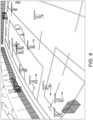
- Figure 4 shows a stage in the process and shows an image from a camera, (such as camera 3b in Figure 3 ) in a situation with a number of players are using a pitch.
- the system can identify individual players by using algorithms and image processing technique, together with their location at any point and therefore can build up a density map of use of any monitored part of the surface at any time.
- density is meant the number of people who pass over that part of the pitch in a predetermined period of time (say 15 minutes). This can therefore provide an indication of the use and therefore wear of the pitch.
- the Figure shows a number of players 6a to 6d, which have been identified by the system as players, typically by virtue of determining a pattern of pixels which is considered to relate, in combination, to a player. Note that players themselves are not specifically individually tracked or identified in preferred embodiments of the system, which is only interested in monitoring use and not in monitoring the activities of individual players.
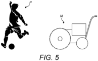
- the system is also able to distinguish between objects using the pitch, for example to distinguish between a first object which is player (shown schematically as P in Figure 5 ), and a second object which is a maintenance machine (shown schematically as M in Figure 5 ).
- a first object which is player shown schematically as P in Figure 5
- a second object which is a maintenance machine shown schematically as M in Figure 5
- the image shown in Figure 5 is only from one angle but a training process using a neural network, as described below, the system is able to detect a player from various angles and positions, as well as maintenance machines and can therefore distinguish between a player using a surface (and therefore wearing out a surface) and a maintenance machine being used to perform a maintenance operation).
- the system can distinguish between players using a pitch or other playing surface and the operation of maintenance machinery so this type of system this can be used by a user to determine that maintenance is being done at correct time intervals and after a particular amount of use.
- the pattern of pixels which will define a player will always be different from the pattern of pixels defining a maintenance machine and therefore the system is able to distinguish between these, perhaps after a learning process.
- more than one type of maintenance machine and operation will be done and the system will generally be taught to recognise each type of different maintenance machine or simply to recognise that any object which is not a player (or for example a stray animal) is a maintenance machine.
- the system may also discriminate other objects, eg balls, animals and so on.
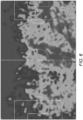
- Figure 6 shows a typical heat map. This is created by obtaining data representative of the number of times a player passes over a particular area on the pitch and converting this to data representative of the density of use (ie amount of times a player passes a particular area in a certain amount of time such as fifteen minutes), so as to obtain a heat map in which more densely used areas are coloured, say red, and less densely used areas are coloured in different colours, say lighter shades of red, yellow and so on.
- the pitch may be divided into a grid having a number of rows and columns defined with each particular area in it defined by a particular grid value.
- Figure 7 shows a typical screen shot that may be viewed by a user either locally, and using apparatus connected locally to the/or each camera, or at a remote monitoring station.
- This may include a video display showing, in real time or near real time, density of use of a pitch as a game progresses or training session and also perhaps with a bar chart showing use over a rolling time period (eg 15 minutes) of say the left third of the pitch 20, the middle third of the pitch 30 and a right third of the pitch 40.
- a rolling time period eg 15 minutes
- FIGS 8 to 10 show schematic screen shots of, a "dashboard" 50 which might be viewed at a control station, provided either locally or remotely.
- pitches can be monitored.
- a user who may be monitoring a number of pitches can select a particular pitch to monitor and can then view heat maps of this 51, 52. This may be done in real time or may be done later using stored information.
- the viewer may also view a snapshot 53 showing players on a pitch at peak time (perhaps a time of maximum density or some other chosen time) where he views the actual image including the distinguished players P.
- the person monitoring can also view daily average use of that pitch (or part of a pitch in part of the display 54) and in this case has asked to view daily average use of a pitch which indicates that on average the first third of the pitch was used for 69% of the time the game of played, the second third 13% and the third 46%. Note that the total percentage may of course be more than 100% as there will be more than one player on the pitch at any time.
- the user can also select the pitch or pitches to monitor.
- the user can also obtain information relating to a usage overview 60, pitch heat map 61, a national overview illustrating statistics nationally 63 or a maintenance schedule 64.
- Figure 9 shows a usage overview screen 61 and this can display information relating to usage over a particular day (at 15 minute interviews in the day), over a week, or over a month, for example, and may include charts including density of use at any time. For example, a particular pitch may monitor at a particularly high rate between around 10am to 10.30am and was not used at all between midnight and 12.30am.
- the individual chart shown on the left part of the Figure 62 can be reproduced as a graph.
- Figure 10 shows all the pitches or playing surfaces the control centre may monitor (shown as "national assets") 66.
- This may be provided in the form of a graph which can be zoomed into to view individual zones or areas, such as the area 67.
- This might be linked to a map provided from a surface such as Google Map and which illustrates the locations of the specific playing surfaces being monitored, together with statistics relating to each surface.
- the "Turn Moss Playing Fields” is used for a monthly average time of 87.54 minutes and the average visit lasts 412 minutes (ie the time when a group of players is seen to be using it and therefore is considered that a visit is being made).
- This also shows that the monthly average busiest day is on a Saturday and illustrates (by regional rankings) how the density of use of this particular asset compares to others, both in a local region and nationally. Other information can be provided.
- An important aspect is monitoring maintenance of pitches and playing surfaces.
- the system can differentiate between objects such as people and maintenance apparatus, it can be used to record when a maintenance machine, such as a roller, grass-cutter or other device, passes over any region.
- a record can be kept of maintenance. This can indicate not only that maintenance was done at a certain time/interval but also, because a record of location is present, record or indicate that density of maintenance in each particular zone or area on a surface or pitch.
- a heat map may be provided. The information can indicate to an operator if one zone, for example, is being maintained better (eg more frequently) than other zones. It may be for example that a groundsman moves a machine over turf in pattern which omits certain areas, which can be detected and thereby rectified.
- the dashboard may have functionality to review the maintenance timing, density etc.
- Figure 11 shows a typical camera system that might be used in non-limiting embodiments. This might incorporate camera 3 or the camera may be a standalone camera and connected to the rest of the system.
- the system includes the camera 3, a video image processing unit 112, a processor 114, a memory 116, a communications unit 118, an enclosure (where the unit is a single unit) 120, a transmitter 122 and a battery or other power source 124 (or a connection to a mains supply, or a sustainable power supply such as a photovoltaic inverter, wind turbine or otherwise).
- a memory may also be provided.
- the camera 3 may be a wide angle fish eye camera. Camera resolution may be chosen according to the field of view and the detailed required.
- the video processing unit 112 may be of any appropriate type and be capable of converting the images into pixel data.
- the processor 114 may, for example, be a Tegra X1 processor.
- the communications unit 118 may be adapted to communicate by wire, by wifi, by mobile telephone, GSM, 3G or 4G telephone or other appropriate means.
- the enclosure may be a waterproof one to ensure that the camera and other equipment cannot be damaged whilst in situ.
- the transmitter 112 may also be waterproof and be appropriate to the communication protocol chosen for the communications unit.
- the unit When the unit is mounted upon a floodlight array, the unit may conveniently be powered by the same power source used to power the lights themselves.
- Figure 12 shows a distributed arrangement in which a number of cameras 3a, 3b or camera unit (such as unit 100 in Figure 11 , which incorporates a camera) are connected to a remote monitoring station 200.
- This includes a server 202 connected to a system logging unit 204, a post processing unit (ie for automated reporting and providing alerts to user) 206, a data API (Application Programming Interface) 208, and a front end interface 212, which can provide the screen display as shown in Figures 8 to 10 .
- a memory with also generally be provided
- the system may use neural networks which may be provided within the processing 112, 114 of an individual unit, or image data in its more raw form may be provided to the processor 202 of central monitoring station 200 and a neural network enabling processing to be done on groups of pixels to identify predetermined recognisable objects such as players or maintenance machines.
- the neural network will be provided at the camera unit 100.
- the remote server or local server
- the central monitoring station 200 Various types of processing may occur at the various units 204 to 210.
- the data API may provide real time data in computer format to software which needs it.
- the data may be provided to many types of software, not only that for monitoring use and maintenance but also, in software for various purposes a user, owner or manager of a playing surface or number of playing surfaces may require in order to determine how their facilities are being used and to optimise the use.
- the camera unit 100 is an intelligent one which can video and elitists to understand the movement of bodies in its field of view.
- the processor 114 may use a neural network based on the Caffe framework.
- the Caffe network is developed by a Barclay Al Research (BAIR) and may be conveniently used, however other frameworks may be used.
- convolutional filters which can act as part of a higher layer of the neural network described above.
- Mathematical convolution operations may be used to assess one or more areas of a lower layer in turn for particular features. Each convolutional operation is tuned to one or several of these features, and scans across the layer looking for that feature. These features may identify gradients, edges or lines in lower layers; object components such as wheels, number plates, or windscreens in medium layers; or full vehicles in higher layers.
- These convolutional filters generate activation or feature maps, showing how strongly a convolutional filter was activated by a particular region of the lower layer, and acting as inputs into the next layer in the network.
- the sequential convolutional process allows the network to pick up features of increasing size, ultimately identifying full vehicles.
- Each time the convolution filters are used a more detailed representation of the features of an object is built up through identifying a higher-order set of features with each pass.
- a lower convolutional layer may identify several circular gradient patterns of different colours, which is later identified in a higher layer as a wheel of a maintenance machine.
- a sequential understanding of the key objects in the image is constructed.
- Recurrent neural network architecture may be used to perform a tracking process, by adding memory to the network, in order to link sequential images together and able tracking to be done.
- the linkage of the sequential images may be carried out such that each object is linked with corresponding objects in subsequent or preceding claim and this helps to identify objects and give a more accurate representation of object type and location coordinates over time.
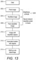
- Data 300 is captured on the camera 3 and this is captured on the basis of a number of single frames which together comprise a sequence and which is then used to generate a detailed pixel image 302 of each scene.
- This image is rectified 304 by a rectification process which adjusts brightness, contracts etc 306.
- the pixel image may be classified 306 by the neural network which classifies the pixels in the frame to obtain the pixel classified image 308.
- a library of still images is used to create a machine learning model.
- the model is fundamentally an advanced statistical compression of the original still images, and turns the still image set (several gigabytes in size) into a streamlined function (tens to hundreds of megabytes in size), where the images were used to inform what the function looks like and does, but where the function is only a series of mathematical instructions which turn a new image into a set of labels.
- the system is trained by giving it many thousands of images and the corresponding labels; the model/function is derived over multiple iterations by comparing the output labels given by the function to the known labels, and adjusting the function appropriately for the next iteration, until the model converges. For example a region within the image may be identified within the model as part of a leg. A different region may be labelled as a brush of a maintenance machine. These would help the model to probabilistically identify the most likely identity of that particular object.
- an image 310 can be obtained which contains the classified object (ie which indicates the different types of object which have been identified and distinguished). Each object can then be associated with a particular location, by simply determining where, in the image, the object is located, and from this, data representative of density of use can be obtained since the presence of a person at a particular location is now known, and by doing this over a time period (such as 15 minutes) a density or heat map 314 can be generated.
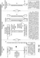
- Figure 14 shows the stage from a set up phase 400, a training phase 402 and an operational phase 404.
- the neural network operates in three main phases.
- the set up phase 400 takes many images from an initial image set 710 and converts these into an initial labelling set 712. Many thousands of images might be processed at this set up stage. The conversion can be done manually labelling each image to identify objects of interest.
- Architecture defining the internal structure of the neural network may comprise a multiple layer structure defined by a very large number of parameters. The combination of the initial image set and the initial labelling set (in which all the objects of interest in each initial image are labelled) are inputs into the neural network end at the set up phase.
- a number of training iterations are carried out.
- a small batch of images 714 are taken from an initial set and the neural network generates trial labels for a small batch of images taken from the initial image set 714, using the current parameters 716 of the neural network as determined in the set up phase.
- the generated labels are compared, in step 718, with actual labels, allowing calculation of the error at a network level. That is, the system tries to apply labels and these are then compared by a user to see if they are accurate.
- This process is then repeated many times (perhaps hundreds of thousands of times) to optimise the parameters and to generate a functional and trained neural network.
- the process is then repeated for other batches of images.
- the combination of inter and intra batch analysis results in the training neural network which accurately recognises images and attributes an accurate label or classification thereto.
- the neural network comprises a multilayer structure which represents the initial labelling set which has been tested and trained against batches of images 714.
- the layers allow assessment of the image to determine an accurate label output 720 for the particular image, and thus identify an object type.
- the output label is very similar to the initial equivalent in the set up phase 400.
- an object type can be identified by the above described process and used by the remainder of the system to generate the array of objects and location coordinates.
- object type is not necessarily a restrictive term but may be used to identify the nature of the object so that specific types of objects can be identified and used by the system.
- an object could be a player, a ball, a whole maintenance machine or merely part of a maintenance machine such as brush or handle bar.
- the object type can be labelled by the system in any appropriate manner.
- object recognition distinguishing and labelling may be done by many different techniques, not only the neural network technique described. Generally methods will involve an initial pixel image being obtained and then the pixel being analysed to distinguished objects. This may be done by pattern recognition or by many other techniques.
- the image capture device may be incorporated into floodlights during manufacture, for example.
Landscapes
- Engineering & Computer Science (AREA)
- Theoretical Computer Science (AREA)
- Physics & Mathematics (AREA)
- General Physics & Mathematics (AREA)
- Computer Vision & Pattern Recognition (AREA)
- Evolutionary Computation (AREA)
- Multimedia (AREA)
- Artificial Intelligence (AREA)
- Health & Medical Sciences (AREA)
- General Health & Medical Sciences (AREA)
- Data Mining & Analysis (AREA)
- Software Systems (AREA)
- Life Sciences & Earth Sciences (AREA)
- Computing Systems (AREA)
- General Engineering & Computer Science (AREA)
- Medical Informatics (AREA)
- Quality & Reliability (AREA)
- Physical Education & Sports Medicine (AREA)
- Databases & Information Systems (AREA)
- Biodiversity & Conservation Biology (AREA)
- Architecture (AREA)
- Civil Engineering (AREA)
- Structural Engineering (AREA)
- Biomedical Technology (AREA)
- Evolutionary Biology (AREA)
- Molecular Biology (AREA)
- Human Computer Interaction (AREA)
- Bioinformatics & Computational Biology (AREA)
- Bioinformatics & Cheminformatics (AREA)
- Mathematical Physics (AREA)
- Signal Processing (AREA)
- Image Analysis (AREA)
Claims (15)
- Spieloberflächenüberwachungssystem, umfassend eine Spieloberfläche (1); eine Bilderfassungseinheit (3), die zum Erfassen von Bildern der Spieloberfläche und von Personen oder Gegenständen darauf angeordnet ist, Verarbeitungsmittel (112) zum Erkennen der Personen oder der Gegenstände und ihres relativen Standorts auf der Spieloberfläche; Mittel zum Unterscheiden zwischen Personen, die die Spieloberfläche (6a-6d) verwenden, und Objekten (M), die für die Wartung der Spieloberfläche verwendet werden, und Mittel zum Verwenden von Informationen, die von den Unterscheidungsmitteln erhalten werden, um die Dichte der Verwendung durch Personen, die die Spieloberfläche verwenden, zu bestimmen, indem Daten erhalten werden, die für die Anzahl darstellend sind, wie oft ein Spieler eine bestimmte Fläche auf dem Spielfeld überquert, und diese in Daten umgewandelt werden, die für die Dichte der Verwendung darstellend sind, um eine Dichte-Wärmekarte (314) zu erhalten, und die Durchführung von Wartungsarbeiten auf der Oberfläche oder einem oder mehreren Teilen davon über einen Zeitraum durch Aufzeichnen bestimmt wird, wenn eine Wartungsmaschine über einen beliebigen Bereich fährt, um anzuzeigen, dass die Wartung zu einem bestimmten Zeitpunkt oder in einem bestimmten Intervall durchgeführt wurde, und Aufzeichnen oder Anzeigen der Wartungsdichte auf einer bestimmten Fläche der Spieloberfläche; wobei das System Mittel zum Bestimmen a) der Verwendungsdichte der Spieloberfläche oder eines oder mehrerer Teile davon durch Personen und b) der von einer Wartungseinrichtung durchgeführten Wartungsarbeiten, indem zwischen Personen, die die Spieloberfläche verwenden, und Wartungsmaschinen über einen bestimmten Zeitraum unterschieden wird, um die Verwendung und Wartung der Oberfläche zu überwachen.
- System nach Anspruch 1, das Mittel zum Darstellen der Dichteinformationen (314) für einen lokalen oder entfernten Benutzer beinhaltet.
- System nach einem der vorhergehenden Ansprüche, wobei die Bilderfassungseinheit Pixeldaten erhält und ein Verarbeitungsmittel umfasst, das dazu konfiguriert ist, die Pixeldaten zu analysieren, um zwischen Personen und anderen Objekten zu unterscheiden.
- System nach einem der vorhergehenden Ansprüche, wobei die Bilderfassungseinheit eine Kamera ist.
- System nach einem der vorhergehenden Ansprüche, wobei die Bilderfassungseinheit Mittel zum Erfassen eines Pixelbildes von Personen oder anderen Vorrichtungen in einer oder mehreren vorbestimmten Flächen der Spieloberfläche; Mittel zum Identifizieren und Klassifizieren des oder jedes Objekts innerhalb des Bildes über eine neuronale Netzwerkverarbeitung unter Verwendung der Pixeldaten, um einen Objekttyp zu erzeugen; Bestimmen von Standortskoordinaten für den oder jeden Objekttyp und Erzeugen eines Arrays von Objekttyp- und Standortskoordinaten im Laufe der Zeit umfasst, um dadurch die Verwendung und/oder Wartung des oder jedes überwachten Teils der Spielobenfläche im Laufe der Zeit zu überwachen.
- System nach Anspruch 5, das für die Verwendung in einer Einrichtungsphase (400), einer Trainingsphase (402) und einer Betriebsphase (404) angeordnet ist, wobei das neuronale Netzwerk in der Trainingsphase und der Betriebsphase verwendet wird.
- System nach Anspruch 6, wobei die Einrichtungsphase Mittel zum Eingeben eines anfänglichen Satzes von Bildern (710) und zum Markieren (712) jedes dieser Bilder oder einer Auswahl dieser beinhaltet; die Trainingsphase die Verwendung der Erfassungseinheit zum Erhalten eines oder mehrerer Bilder und das Anwenden des neuronalen Netzwerks für die Erzeugung einer oder mehrerer Versuchsmarkierungen (714) für in den Bildern gefundene Objekte; das Überprüfen der zugewiesenen Markierung auf Fehler (718) und das Verwenden von Fehlern für die Anpassung von in dem neuronalen Netzwerk eingestellten Parametern und dann das ein- oder mehrmalige Wiederholen der Markierungsschritte für die Reduzierung von Fehlern umfasst.
- System nach Anspruch 6 oder 7, wobei in der Trainingsphase die Schritte der Markierung, der Fehlererkennung und der Parameteranpassung eine Mehrzahl von Malen wiederholt werden, bis ein gewünschtes Vertrauensniveau erreicht ist.
- System nach einem der Ansprüche 6 bis 8, wobei während einer Betriebsphase des neuronalen Netzwerkes ein einzelnes Bild von dem Bilderfassungsmittel erhalten wird, dem neuronalen Netzwerk zugeführt wird und das neuronale Netzwerk jedem der Pixel, die es für ein Objekt hält, Markierungen zuweist.
- System nach Anspruch 7, wobei einzelne Pixel durch den Prozessor des neuronalen Netzwerkes klassifiziert und gruppiert werden, um einen klassifizierten Objekttyp auszubilden.
- System nach Anspruch 10, wobei die klassifizierten Pixel unter Verwendung einer anfänglichen Bibliothek von Standbildern erzeugt werden, um ein maschinelles Lernmodell zu erstellen, das mit jedem Pixel verglichen wird, um dadurch das Pixel zu klassifizieren.
- System nach einem der vorhergehenden Ansprüche, wobei eine Mehrzahl von Bilderfassungsvorrichtungen bereitgestellt wird, um Teile eines Feldes, eine Mehrzahl von Feldern oder eine Mehrzahl von Feldern an einem entfernten Standort zu überwachen, wobei jede Bilderfassungsvorrichtung einem Mittel zum Übertragen von Daten an eine zentrale Überwachungsstation zugeordnet ist.
- System nach Anspruch 12, wobei die zentrale Überwachungsstation Daten von jeder Bilderfassungseinheit empfängt und mit Software für die Analyse und/oder Anzeige dieser Daten für einen Benutzer versehen ist.
- System nach Anspruch 12 oder 13, wobei die/jede Erfassungseinheit mit der zentralen Steuereinheit über eine Kommunikationsverknüpfung kommuniziert.
- Verfahren zum Überwachen der Wartung einer Spieloberfläche, umfassend das Bereitstellen eines Systems nach einem der vorhergehenden Ansprüche, das Erhalten der überwachten Informationen, die für die Dichte der Verwendung und der Wartung darstellend sind, und das Verwenden der überwachten Informationen für die Überwachung der Verwendung und der Wartung der Spieloberfläche über einen Zeitraum.
Applications Claiming Priority (2)
| Application Number | Priority Date | Filing Date | Title |
|---|---|---|---|
| GB1714056.7A GB2566067B (en) | 2017-09-01 | 2017-09-01 | Maintenance of playing surfaces |
| PCT/GB2018/052363 WO2019043357A1 (en) | 2017-09-01 | 2018-08-21 | MONITORING THE MAINTENANCE OF A GAME SURFACE |
Publications (3)
| Publication Number | Publication Date |
|---|---|
| EP3676749A1 EP3676749A1 (de) | 2020-07-08 |
| EP3676749B1 true EP3676749B1 (de) | 2023-06-07 |
| EP3676749C0 EP3676749C0 (de) | 2023-06-07 |
Family
ID=60050668
Family Applications (1)
| Application Number | Title | Priority Date | Filing Date |
|---|---|---|---|
| EP18759718.2A Active EP3676749B1 (de) | 2017-09-01 | 2018-08-21 | Überwachung der wartung der spielfläche |
Country Status (5)
| Country | Link |
|---|---|
| US (1) | US11062146B2 (de) |
| EP (1) | EP3676749B1 (de) |
| AU (1) | AU2018325433B2 (de) |
| GB (1) | GB2566067B (de) |
| WO (1) | WO2019043357A1 (de) |
Families Citing this family (2)
| Publication number | Priority date | Publication date | Assignee | Title |
|---|---|---|---|---|
| CN110163234B (zh) * | 2018-10-10 | 2023-04-18 | 腾讯科技(深圳)有限公司 | 一种模型训练方法、装置和存储介质 |
| US11769245B2 (en) | 2021-10-21 | 2023-09-26 | Goodrich Corporation | Systems and methods of monitoring cargo load systems for damage detection |
Family Cites Families (17)
| Publication number | Priority date | Publication date | Assignee | Title |
|---|---|---|---|---|
| US4769700A (en) * | 1981-11-20 | 1988-09-06 | Diffracto Ltd. | Robot tractors |
| FR2648071B1 (fr) * | 1989-06-07 | 1995-05-19 | Onet | Procede et appareil autonomes de nettoyage automatique de sol par execution de missions programmees |
| ES2165783B1 (es) * | 1999-11-10 | 2003-06-16 | Garcia Lucia Janez | Sistema y metodo de vision artificial para ayuda al arbitraje en competiciones deportivas. |
| GB0105421D0 (en) * | 2001-03-06 | 2001-04-25 | Prozone Holdings Ltd | Sport analysis system and method |
| GB2386971B (en) * | 2002-03-26 | 2005-11-30 | Mcmurtry Ltd | Method of operating an automated land maintenance vehicle |
| US7844270B2 (en) * | 2003-05-21 | 2010-11-30 | Nortel Networks Limited | Call transfer for an integrated wireline and wireless service using a temporary directory number |
| GB0420204D0 (en) * | 2004-09-11 | 2004-10-13 | Univ Abertay | "Object recognition system" |
| GB2442787B (en) * | 2005-10-22 | 2010-06-09 | Tim Lodge | Golf green roughness meter |
| US20080021651A1 (en) * | 2006-07-18 | 2008-01-24 | John Richard Seeley | Performance Assessment and Information System Based on Sports Ball Motion |
| KR101173786B1 (ko) * | 2010-11-05 | 2012-08-16 | 성균관대학교산학협력단 | 신경망을 이용한 이동 물체의 혼잡도 측정 시스템 및 방법 |
| CN104023520B (zh) * | 2011-12-19 | 2016-06-08 | 尤尼斯科技公司 | 远程传感和调适灌溉系统 |
| US9202526B2 (en) * | 2012-05-14 | 2015-12-01 | Sstatzz Oy | System and method for viewing videos and statistics of sports events |
| US9538702B2 (en) * | 2014-12-22 | 2017-01-10 | Irobot Corporation | Robotic mowing of separated lawn areas |
| CA2913432A1 (en) * | 2015-11-26 | 2016-01-27 | Robert Zakaluk | System and method for identifying, analyzing, and reporting on players in a game from video |
| US10002313B2 (en) * | 2015-12-15 | 2018-06-19 | Sighthound, Inc. | Deeply learned convolutional neural networks (CNNS) for object localization and classification |
| US10094077B1 (en) * | 2016-01-08 | 2018-10-09 | Joseph Santoiemma | Tennis court playing surface removal device |
| JP6794884B2 (ja) * | 2017-03-15 | 2020-12-02 | 富士通株式会社 | 人工芝の維持管理プログラム、人工芝の維持管理方法、及び人工芝の維持管理装置 |
-
2017
- 2017-09-01 GB GB1714056.7A patent/GB2566067B/en active Active
-
2018
- 2018-08-21 WO PCT/GB2018/052363 patent/WO2019043357A1/en not_active Ceased
- 2018-08-21 US US16/642,538 patent/US11062146B2/en active Active
- 2018-08-21 AU AU2018325433A patent/AU2018325433B2/en active Active
- 2018-08-21 EP EP18759718.2A patent/EP3676749B1/de active Active
Non-Patent Citations (1)
| Title |
|---|
| PIPER A. G. G: "Turf Monitoring Technology to Aid in Benchmarking and Maintenance of Sporting Fields", 31 December 2004 (2004-12-31), pages 1 - 61, XP055826199, Retrieved from the Internet <URL:https://eprints.usq.edu.au/24/1/AndrewPIPER-2004.pdf> [retrieved on 20210721] * |
Also Published As
| Publication number | Publication date |
|---|---|
| US20210073553A1 (en) | 2021-03-11 |
| GB2566067A (en) | 2019-03-06 |
| EP3676749C0 (de) | 2023-06-07 |
| GB2566067B (en) | 2020-02-19 |
| GB201714056D0 (en) | 2017-10-18 |
| AU2018325433A1 (en) | 2020-03-12 |
| US11062146B2 (en) | 2021-07-13 |
| EP3676749A1 (de) | 2020-07-08 |
| AU2018325433B2 (en) | 2021-10-14 |
| WO2019043357A1 (en) | 2019-03-07 |
Similar Documents
| Publication | Publication Date | Title |
|---|---|---|
| CN111723633B (zh) | 一种基于深度数据的人员行为模式分析方法和系统 | |
| US10949676B2 (en) | Aerial monitoring system and method for identifying and locating object features | |
| Duniway et al. | Rangeland and pasture monitoring: an approach to interpretation of high-resolution imagery focused on observer calibration for repeatability | |
| CN107871120A (zh) | 基于机器学习的体育赛事理解系统及方法 | |
| WO2016157152A1 (en) | System for the automated analisys of a sporting match | |
| CN106845432A (zh) | 一种人脸与人体共同检测的方法和设备 | |
| CN119107597B (zh) | 一种用于风电吊装现场的三维可视化安全监控方法 | |
| CN103260015A (zh) | 基于RGB-Depth摄像头的三维可视监控系统 | |
| US11062146B2 (en) | Maintenance of playing surfaces | |
| CN119229526A (zh) | 基于机器视觉的电力作业风险行为违章智能识别方法 | |
| CN119942442A (zh) | 一种基于人工智能的农作物虫害监测方法及系统 | |
| CN117768610A (zh) | 基于多目标识别的高速铁路周界入侵风险监测方法及系统 | |
| CN110309737A (zh) | 一种应用于香烟柜台的信息处理方法、装置及系统 | |
| CN116895078A (zh) | 生产区域脱岗检测方法及系统 | |
| CN118780621B (zh) | 基于建筑工程安全标准的施工风险管理方法及系统 | |
| CN106022311A (zh) | 基于城市监控视频识别的应急事件发现方法及系统 | |
| CN119478770B (zh) | 基于gis的自动视频巡检系统 | |
| CN103824083A (zh) | 基于叶片完备局部二值特征的Web在线物种识别方法 | |
| CN120873747A (zh) | 面向电力设备安全主动干预的目标检测预警方法和系统 | |
| CN118015737A (zh) | 基于物联网的智能门锁联合控制系统 | |
| KR20250057197A (ko) | 스포츠 경기장 내 잔디의 생육 상태 및 병충해 발생을 예측하는 잔디 관리 시스템 및 그 방법 | |
| CN117079350A (zh) | 支持多路视觉分析的便携体育测试方法及系统 | |
| CN116886874A (zh) | 一种生态园安防监控预警数据的采集方法及其系统 | |
| CN120147947B (zh) | 一种基于用户行为特征分析的电力营销现场安全监控方法与系统 | |
| CN112767301A (zh) | 作物苗数的确定方法及装置、测量系统 |
Legal Events
| Date | Code | Title | Description |
|---|---|---|---|
| STAA | Information on the status of an ep patent application or granted ep patent |
Free format text: STATUS: UNKNOWN |
|
| STAA | Information on the status of an ep patent application or granted ep patent |
Free format text: STATUS: THE INTERNATIONAL PUBLICATION HAS BEEN MADE |
|
| PUAI | Public reference made under article 153(3) epc to a published international application that has entered the european phase |
Free format text: ORIGINAL CODE: 0009012 |
|
| STAA | Information on the status of an ep patent application or granted ep patent |
Free format text: STATUS: REQUEST FOR EXAMINATION WAS MADE |
|
| 17P | Request for examination filed |
Effective date: 20200210 |
|
| AK | Designated contracting states |
Kind code of ref document: A1 Designated state(s): AL AT BE BG CH CY CZ DE DK EE ES FI FR GB GR HR HU IE IS IT LI LT LU LV MC MK MT NL NO PL PT RO RS SE SI SK SM TR |
|
| AX | Request for extension of the european patent |
Extension state: BA ME |
|
| DAV | Request for validation of the european patent (deleted) | ||
| DAX | Request for extension of the european patent (deleted) | ||
| STAA | Information on the status of an ep patent application or granted ep patent |
Free format text: STATUS: EXAMINATION IS IN PROGRESS |
|
| 17Q | First examination report despatched |
Effective date: 20210205 |
|
| REG | Reference to a national code |
Ref country code: DE Ref legal event code: R079 Ref document number: 602018051145 Country of ref document: DE Free format text: PREVIOUS MAIN CLASS: G06K0009000000 Ipc: G06V0010000000 |
|
| GRAP | Despatch of communication of intention to grant a patent |
Free format text: ORIGINAL CODE: EPIDOSNIGR1 |
|
| STAA | Information on the status of an ep patent application or granted ep patent |
Free format text: STATUS: GRANT OF PATENT IS INTENDED |
|
| RIC1 | Information provided on ipc code assigned before grant |
Ipc: G06V 10/00 20220101AFI20220713BHEP |
|
| INTG | Intention to grant announced |
Effective date: 20220728 |
|
| RBV | Designated contracting states (corrected) |
Designated state(s): AL AT BE BG CH CY CZ DE DK EE ES FI FR GR HR HU IE IS IT LI LT LU LV MC MK MT NL NO PL PT RO RS SE SI SK SM TR |
|
| GRAJ | Information related to disapproval of communication of intention to grant by the applicant or resumption of examination proceedings by the epo deleted |
Free format text: ORIGINAL CODE: EPIDOSDIGR1 |
|
| STAA | Information on the status of an ep patent application or granted ep patent |
Free format text: STATUS: EXAMINATION IS IN PROGRESS |
|
| INTC | Intention to grant announced (deleted) | ||
| GRAP | Despatch of communication of intention to grant a patent |
Free format text: ORIGINAL CODE: EPIDOSNIGR1 |
|
| STAA | Information on the status of an ep patent application or granted ep patent |
Free format text: STATUS: GRANT OF PATENT IS INTENDED |
|
| GRAS | Grant fee paid |
Free format text: ORIGINAL CODE: EPIDOSNIGR3 |
|
| INTG | Intention to grant announced |
Effective date: 20230109 |
|
| GRAA | (expected) grant |
Free format text: ORIGINAL CODE: 0009210 |
|
| STAA | Information on the status of an ep patent application or granted ep patent |
Free format text: STATUS: THE PATENT HAS BEEN GRANTED |
|
| AK | Designated contracting states |
Kind code of ref document: B1 Designated state(s): AL AT BE BG CH CY CZ DE DK EE ES FI FR GR HR HU IE IS IT LI LT LU LV MC MK MT NL NO PL PT RO RS SE SI SK SM TR |
|
| REG | Reference to a national code |
Ref country code: CH Ref legal event code: EP Ref country code: AT Ref legal event code: REF Ref document number: 1577282 Country of ref document: AT Kind code of ref document: T Effective date: 20230615 |
|
| REG | Reference to a national code |
Ref country code: DE Ref legal event code: R096 Ref document number: 602018051145 Country of ref document: DE |
|
| U01 | Request for unitary effect filed |
Effective date: 20230607 |
|
| U07 | Unitary effect registered |
Designated state(s): AT BE BG DE DK EE FI FR IT LT LU LV MT NL PT SE SI Effective date: 20230612 |
|
| U20 | Renewal fee for the european patent with unitary effect paid |
Year of fee payment: 6 Effective date: 20230815 |
|
| REG | Reference to a national code |
Ref country code: LT Ref legal event code: MG9D |
|
| PG25 | Lapsed in a contracting state [announced via postgrant information from national office to epo] |
Ref country code: NO Free format text: LAPSE BECAUSE OF FAILURE TO SUBMIT A TRANSLATION OF THE DESCRIPTION OR TO PAY THE FEE WITHIN THE PRESCRIBED TIME-LIMIT Effective date: 20230907 Ref country code: ES Free format text: LAPSE BECAUSE OF FAILURE TO SUBMIT A TRANSLATION OF THE DESCRIPTION OR TO PAY THE FEE WITHIN THE PRESCRIBED TIME-LIMIT Effective date: 20230607 |
|
| PG25 | Lapsed in a contracting state [announced via postgrant information from national office to epo] |
Ref country code: RS Free format text: LAPSE BECAUSE OF FAILURE TO SUBMIT A TRANSLATION OF THE DESCRIPTION OR TO PAY THE FEE WITHIN THE PRESCRIBED TIME-LIMIT Effective date: 20230607 Ref country code: HR Free format text: LAPSE BECAUSE OF FAILURE TO SUBMIT A TRANSLATION OF THE DESCRIPTION OR TO PAY THE FEE WITHIN THE PRESCRIBED TIME-LIMIT Effective date: 20230607 Ref country code: GR Free format text: LAPSE BECAUSE OF FAILURE TO SUBMIT A TRANSLATION OF THE DESCRIPTION OR TO PAY THE FEE WITHIN THE PRESCRIBED TIME-LIMIT Effective date: 20230908 |
|
| PG25 | Lapsed in a contracting state [announced via postgrant information from national office to epo] |
Ref country code: SK Free format text: LAPSE BECAUSE OF FAILURE TO SUBMIT A TRANSLATION OF THE DESCRIPTION OR TO PAY THE FEE WITHIN THE PRESCRIBED TIME-LIMIT Effective date: 20230607 |
|
| PG25 | Lapsed in a contracting state [announced via postgrant information from national office to epo] |
Ref country code: IS Free format text: LAPSE BECAUSE OF FAILURE TO SUBMIT A TRANSLATION OF THE DESCRIPTION OR TO PAY THE FEE WITHIN THE PRESCRIBED TIME-LIMIT Effective date: 20231007 |
|
| PG25 | Lapsed in a contracting state [announced via postgrant information from national office to epo] |
Ref country code: SM Free format text: LAPSE BECAUSE OF FAILURE TO SUBMIT A TRANSLATION OF THE DESCRIPTION OR TO PAY THE FEE WITHIN THE PRESCRIBED TIME-LIMIT Effective date: 20230607 Ref country code: SK Free format text: LAPSE BECAUSE OF FAILURE TO SUBMIT A TRANSLATION OF THE DESCRIPTION OR TO PAY THE FEE WITHIN THE PRESCRIBED TIME-LIMIT Effective date: 20230607 Ref country code: RO Free format text: LAPSE BECAUSE OF FAILURE TO SUBMIT A TRANSLATION OF THE DESCRIPTION OR TO PAY THE FEE WITHIN THE PRESCRIBED TIME-LIMIT Effective date: 20230607 Ref country code: IS Free format text: LAPSE BECAUSE OF FAILURE TO SUBMIT A TRANSLATION OF THE DESCRIPTION OR TO PAY THE FEE WITHIN THE PRESCRIBED TIME-LIMIT Effective date: 20231007 Ref country code: CZ Free format text: LAPSE BECAUSE OF FAILURE TO SUBMIT A TRANSLATION OF THE DESCRIPTION OR TO PAY THE FEE WITHIN THE PRESCRIBED TIME-LIMIT Effective date: 20230607 |
|
| PG25 | Lapsed in a contracting state [announced via postgrant information from national office to epo] |
Ref country code: PL Free format text: LAPSE BECAUSE OF FAILURE TO SUBMIT A TRANSLATION OF THE DESCRIPTION OR TO PAY THE FEE WITHIN THE PRESCRIBED TIME-LIMIT Effective date: 20230607 |
|
| REG | Reference to a national code |
Ref country code: DE Ref legal event code: R097 Ref document number: 602018051145 Country of ref document: DE |
|
| PG25 | Lapsed in a contracting state [announced via postgrant information from national office to epo] |
Ref country code: MC Free format text: LAPSE BECAUSE OF FAILURE TO SUBMIT A TRANSLATION OF THE DESCRIPTION OR TO PAY THE FEE WITHIN THE PRESCRIBED TIME-LIMIT Effective date: 20230607 |
|
| REG | Reference to a national code |
Ref country code: CH Ref legal event code: PL |
|
| PG25 | Lapsed in a contracting state [announced via postgrant information from national office to epo] |
Ref country code: MC Free format text: LAPSE BECAUSE OF FAILURE TO SUBMIT A TRANSLATION OF THE DESCRIPTION OR TO PAY THE FEE WITHIN THE PRESCRIBED TIME-LIMIT Effective date: 20230607 |
|
| PLBE | No opposition filed within time limit |
Free format text: ORIGINAL CODE: 0009261 |
|
| STAA | Information on the status of an ep patent application or granted ep patent |
Free format text: STATUS: NO OPPOSITION FILED WITHIN TIME LIMIT |
|
| PG25 | Lapsed in a contracting state [announced via postgrant information from national office to epo] |
Ref country code: CH Free format text: LAPSE BECAUSE OF NON-PAYMENT OF DUE FEES Effective date: 20230831 |
|
| 26N | No opposition filed |
Effective date: 20240308 |
|
| REG | Reference to a national code |
Ref country code: IE Ref legal event code: MM4A |
|
| PG25 | Lapsed in a contracting state [announced via postgrant information from national office to epo] |
Ref country code: IE Free format text: LAPSE BECAUSE OF NON-PAYMENT OF DUE FEES Effective date: 20230821 |
|
| PG25 | Lapsed in a contracting state [announced via postgrant information from national office to epo] |
Ref country code: IE Free format text: LAPSE BECAUSE OF NON-PAYMENT OF DUE FEES Effective date: 20230821 |
|
| U20 | Renewal fee for the european patent with unitary effect paid |
Year of fee payment: 7 Effective date: 20240812 |
|
| PG25 | Lapsed in a contracting state [announced via postgrant information from national office to epo] |
Ref country code: CY Free format text: LAPSE BECAUSE OF FAILURE TO SUBMIT A TRANSLATION OF THE DESCRIPTION OR TO PAY THE FEE WITHIN THE PRESCRIBED TIME-LIMIT; INVALID AB INITIO Effective date: 20180821 |
|
| PG25 | Lapsed in a contracting state [announced via postgrant information from national office to epo] |
Ref country code: HU Free format text: LAPSE BECAUSE OF FAILURE TO SUBMIT A TRANSLATION OF THE DESCRIPTION OR TO PAY THE FEE WITHIN THE PRESCRIBED TIME-LIMIT; INVALID AB INITIO Effective date: 20180821 |
|
| U20 | Renewal fee for the european patent with unitary effect paid |
Year of fee payment: 8 Effective date: 20250813 |
|
| PG25 | Lapsed in a contracting state [announced via postgrant information from national office to epo] |
Ref country code: TR Free format text: LAPSE BECAUSE OF FAILURE TO SUBMIT A TRANSLATION OF THE DESCRIPTION OR TO PAY THE FEE WITHIN THE PRESCRIBED TIME-LIMIT Effective date: 20230607 |