EP3676711B1 - Bereitstellung von feinkörniger dienstqualität (qos) mit interpolation für partitionierte ressourcen in prozessorbasierten systemen - Google Patents
Bereitstellung von feinkörniger dienstqualität (qos) mit interpolation für partitionierte ressourcen in prozessorbasierten systemen Download PDFInfo
- Publication number
- EP3676711B1 EP3676711B1 EP18762422.6A EP18762422A EP3676711B1 EP 3676711 B1 EP3676711 B1 EP 3676711B1 EP 18762422 A EP18762422 A EP 18762422A EP 3676711 B1 EP3676711 B1 EP 3676711B1
- Authority
- EP
- European Patent Office
- Prior art keywords
- resource
- memory
- cache
- partitioned
- allocation
- Prior art date
- Legal status (The legal status is an assumption and is not a legal conclusion. Google has not performed a legal analysis and makes no representation as to the accuracy of the status listed.)
- Active
Links
Images


Classifications
-
- G—PHYSICS
- G06—COMPUTING OR CALCULATING; COUNTING
- G06F—ELECTRIC DIGITAL DATA PROCESSING
- G06F12/00—Accessing, addressing or allocating within memory systems or architectures
- G06F12/02—Addressing or allocation; Relocation
- G06F12/08—Addressing or allocation; Relocation in hierarchically structured memory systems, e.g. virtual memory systems
- G06F12/0802—Addressing of a memory level in which the access to the desired data or data block requires associative addressing means, e.g. caches
- G06F12/0844—Multiple simultaneous or quasi-simultaneous cache accessing
- G06F12/0846—Cache with multiple tag or data arrays being simultaneously accessible
- G06F12/0848—Partitioned cache, e.g. separate instruction and operand caches
-
- G—PHYSICS
- G06—COMPUTING OR CALCULATING; COUNTING
- G06F—ELECTRIC DIGITAL DATA PROCESSING
- G06F12/00—Accessing, addressing or allocating within memory systems or architectures
- G06F12/02—Addressing or allocation; Relocation
- G06F12/0223—User address space allocation, e.g. contiguous or non contiguous base addressing
- G06F12/023—Free address space management
-
- G—PHYSICS
- G06—COMPUTING OR CALCULATING; COUNTING
- G06F—ELECTRIC DIGITAL DATA PROCESSING
- G06F12/00—Accessing, addressing or allocating within memory systems or architectures
- G06F12/02—Addressing or allocation; Relocation
- G06F12/08—Addressing or allocation; Relocation in hierarchically structured memory systems, e.g. virtual memory systems
- G06F12/0802—Addressing of a memory level in which the access to the desired data or data block requires associative addressing means, e.g. caches
- G06F12/0806—Multiuser, multiprocessor or multiprocessing cache systems
- G06F12/0842—Multiuser, multiprocessor or multiprocessing cache systems for multiprocessing or multitasking
-
- G—PHYSICS
- G06—COMPUTING OR CALCULATING; COUNTING
- G06F—ELECTRIC DIGITAL DATA PROCESSING
- G06F13/00—Interconnection of, or transfer of information or other signals between, memories, input/output devices or central processing units
- G06F13/14—Handling requests for interconnection or transfer
- G06F13/16—Handling requests for interconnection or transfer for access to memory bus
- G06F13/1605—Handling requests for interconnection or transfer for access to memory bus based on arbitration
- G06F13/1652—Handling requests for interconnection or transfer for access to memory bus based on arbitration in a multiprocessor architecture
- G06F13/1663—Access to shared memory
-
- G—PHYSICS
- G06—COMPUTING OR CALCULATING; COUNTING
- G06F—ELECTRIC DIGITAL DATA PROCESSING
- G06F9/00—Arrangements for program control, e.g. control units
- G06F9/06—Arrangements for program control, e.g. control units using stored programs, i.e. using an internal store of processing equipment to receive or retain programs
- G06F9/46—Multiprogramming arrangements
- G06F9/50—Allocation of resources, e.g. of the central processing unit [CPU]
- G06F9/5061—Partitioning or combining of resources
-
- G—PHYSICS
- G06—COMPUTING OR CALCULATING; COUNTING
- G06F—ELECTRIC DIGITAL DATA PROCESSING
- G06F2212/00—Indexing scheme relating to accessing, addressing or allocation within memory systems or architectures
- G06F2212/10—Providing a specific technical effect
- G06F2212/1041—Resource optimization
- G06F2212/1044—Space efficiency improvement
-
- G—PHYSICS
- G06—COMPUTING OR CALCULATING; COUNTING
- G06F—ELECTRIC DIGITAL DATA PROCESSING
- G06F2212/00—Indexing scheme relating to accessing, addressing or allocation within memory systems or architectures
- G06F2212/28—Using a specific disk cache architecture
- G06F2212/282—Partitioned cache
-
- G—PHYSICS
- G06—COMPUTING OR CALCULATING; COUNTING
- G06F—ELECTRIC DIGITAL DATA PROCESSING
- G06F2212/00—Indexing scheme relating to accessing, addressing or allocation within memory systems or architectures
- G06F2212/70—Details relating to dynamic memory management
Definitions
- the technology of the disclosure relates generally to partitioned resources in processor-based systems, and, in particular, to Quality of Service (QoS) mechanisms for partitioned resources.
- QoS Quality of Service
- processor-based systems provide resources, such as system caches and/or memory access bandwidth, which may be shared among multiple resource clients.
- resources such as system caches and/or memory access bandwidth, which may be shared among multiple resource clients.
- a resource may be subdivided into partitions that may be operated and/or accessed largely independently of one another.
- a system cache e.g., a last-level cache, as a non-limiting example
- Cache access operations by different resource clients may be assigned to one of the cache partitions using conventional address-to-partition mapping techniques based on, for example, hashes of memory addresses of cache access operations.
- a Quality of Service (QoS) mechanism may selectively allocate portions of a resource among difference resource clients, which may operate under different priorities, relative importance, and/or performance goals. For instance, in the cache example described above, a "way mask" (i.e., a bit mask including a bit for each cache way) corresponding to a resource client may be used to allocate a subset of the cache ways for each cache partition for use by that resource client.
- a 20-way set-associative cache may be subdivided into eight (8) partitions, with each resource client's way mask having 20 bits to indicate which of the 20 ways are allocated to that resource client. Because each resource client's way mask is applied to all partitions, the minimum cache space that can be allocated to each resource client is 5%, or one (1) of the 20 ways over the eight (8) partitions.
- memory access bandwidth may also be allocated using conceptually similar controls.
- a processor-based system may provide four (4) memory controllers as memory access bandwidth providers.
- Each resource client may be assigned a "memory stride value" of four (4) bits to indicate how requests for memory bandwidth are weighted for that resource client, with a lower memory stride value indicating a higher weight. Because the memory stride value may have 16 different values (i.e., 0-15), the minimum memory access bandwidth that can be allocated to each resource client is 6.25% (or 1/16) of the total memory access bandwidth.
- finer-grained QoS control may be desirable for allocation of shared resources.
- the QoS mechanisms described above permit only relatively coarse-grained controls that limit allocation resolution and restrict the number of resource clients that may access a given shared resource.
- many mechanisms for implementing fine-grained QoS control may result in higher hardware implementation costs.
- a cache controller of a shared cache memory system comprising a plurality of cache lines.
- the cache controller comprises a cache allocation circuit providing a minimum mapping bitmask for mapping a Quality of Service (QoS) class to a minimum partition of the cache lines, and a maximum mapping bitmask for mapping the QoS class to a maximum partition of the cache lines.
- QoS Quality of Service
- a processor-based system provides a partitioned resource (i.e., a system cache or memory access bandwidth to a shared system memory, as non-limiting examples) that is subdivided into a plurality of partitions and configured to service a plurality of resource clients. For each combination of resource client and partition, an allocation indicator is provided to indicate an allocation of the partition for the resource client.
- a partitioned resource i.e., a system cache or memory access bandwidth to a shared system memory, as non-limiting examples
- an allocation indicator is provided to indicate an allocation of the partition for the resource client.
- aspects in which the partitioned resource is a partitioned cache having a plurality of ways may provide an allocation indicator to indicate how many ways of the partition may be allocated to the resource client.
- aspects in which the partitioned resource is a plurality of memory access bandwidth providers may provide that the allocation indicator indicates a stride to be applied by a memory controller when performing a memory access operation for the resource client.
- each allocation indicator may be different for each combination of resource client and partition, interpolation of the allocation indicators provides a higher-resolution aggregate resource allocation for each resource client. For instance, if the partitioned resource is a 10-way set-associative cache divided into four (4) partitions, conventional QoS mechanisms would only allow the cache to be allocated with a minimum resolution of 10% (i.e., a minimum allocation is 1 way out of 10).
- the allocation indicators for a given resource client may vary for each partition. As a non-limiting example, a resource client may be allocated 50% of the first and second partitions, and 60% of the third and fourth partitions. This results in a total aggregate allocation of the cache of 55% for the resource client.
- a processor-based system for providing fine-grained QoS control of partitioned resources.
- the processor-based system comprises a partitioned resource subdivided into a plurality of partitions and configured to service a plurality of resource clients.
- the processor-based system further comprises a resource allocation agent and a plurality of allocation indicators, each corresponding to a partition of the plurality of partitions and a resource client of a plurality of resource clients, and representing an allocation of the partition for the resource client.
- the resource allocation agent is configured to allocate the partitioned resource among the plurality of resource clients based on an interpolation of the plurality of allocation indicators for each resource client of the plurality of resource clients.
- a processor-based system for providing fine-grained QoS control of partitioned resources.
- the processor-based system comprises a means for allocating a partitioned resource, subdivided into a plurality of partitions, among a plurality of resource clients based on an interpolation of a plurality of allocation indicators, each corresponding to a partition of the plurality of partitions and a resource client of the plurality of resource clients, and representing an allocation of the partition for the resource client.
- a method for providing fine-grained QoS control of partitioned resources comprises allocating, by a resource allocation agent of a processor-based system, a partitioned resource, subdivided into a plurality of partitions, among a plurality of resource clients based on an interpolation of a plurality of allocation indicators, each corresponding to a partition of the plurality of partitions and a resource client of the plurality of resource clients, and representing an allocation of the partition for the resource client.
- a non-transitory computer-readable medium stores thereon computer-executable instructions which, when executed by a processor, cause the processor to allocate a partitioned resource, subdivided into a plurality of partitions, among a plurality of resource clients based on an interpolation of a plurality of allocation indicators, each corresponding to a partition of the plurality of partitions and a resource client of the plurality of resource clients, and representing an allocation of the partition for the resource client.
- FIG. 1 illustrates an exemplary processor-based system 100 that includes a central processing unit (CPU) 102 and a partitioned resource 104 that is shared among multiple resource clients 106(0)-106(C).
- the partitioned resource 104 may comprise a system cache, such as a last-level cache, and/or memory access bandwidth for a shared system memory accessible via a plurality of memory controllers (not shown).
- the resource clients 106(0)-106(C) may comprise concurrently executing software processes, virtual machines, hardware devices, or other entities configured to access the partitioned resource 104, as non-limiting examples.
- processor-based system 100 of Figure 1 may encompass any one of known digital logic elements, semiconductor circuits, and processing cores, and/or memory structures, among other elements, or combinations thereof. Aspects described herein are not restricted to any particular arrangement of elements, and the disclosed techniques may be easily extended to various structures and layouts on semiconductor dies or packages. It is to be understood that some aspects of the processor-based system 100 may include elements in addition to those illustrated in Figure 1 .
- the processor-based system 100 provides that the partitioned resource 104 is subdivided into a plurality of partitions 108(0)-108(P), each of which may be further divided into sub-units that can be selectively allocated among the resource clients 106(0)-106(C).
- the partitioned resource 104 comprises a system cache (e.g., a last-level cache, as a non-limiting example)
- the partitions 108(0)-108(P) may comprise cache "slices" or "instances,” each of which provides a same number of cache ways.
- aspects of the processor-based system 100 in which the partitioned resource 104 comprises memory access bandwidth providers for a shared system memory may provide that each of the partitions 108(0)-108(P) comprises a memory access bandwidth provider such as a memory controller.
- an access request 110 from a resource client 106(0)-106(C), such as the resource client 106(0) is assigned to one of the partitions 108(0)-108(P) based on, for example, a hash of a memory address associated with the access request 110.
- the processor-based system 100 of Figure 1 provides a resource allocation agent 112. While the resource allocation agent 112 is illustrated as a standalone element in Figure 1 , in some aspects the resource allocation agent 112 may be integrated into the CPU 102, into a cache controller (not shown) or a memory management unit (MMU) (not shown), integrated into or distributed across other elements of the processor-based system 100, and/or implemented in part by a software entity (not shown) such as an operating system or a hypervisor executed by the CPU 102 of the processor-based system 100.
- the resource allocation agent 112 employs a plurality of allocation indicators 114(0)-114(C), 114'(0)-114'(C) associated with the partitions 108(0)-108(P).
- Each of the allocation indicators 114(0)-114(C), 114'(0)-114'(C) corresponds to a unique combination of one of the resource clients 106(0)-106(C) and one of the partitions 108(0)-108(P), and represents an allocation of the partition 108(0)-108(P) for the corresponding resource client 106(0)-106(C).
- the allocation indicator 114(0) corresponds to the partition 108(0) for the resource client 106(0)
- the allocation indicator 114'(0) corresponds to the partition 108(P) for the resource client 106(0).
- either the allocation indicator 114(0) or the allocation indicator 114'(0) will be used by the resource allocation agent 112 to determine how much of the corresponding partition 108(0), 108(P) may be allocated to the resource client 106(0) to satisfy the access request 110.
- each of the allocation indicators 114(0)-114(C), 114'(0)-114'(C) for a given one of the resource clients 106(0)-106(C) may vary across different partitions 108(0)-108(P).
- a resource client such as the resource client 106(0) may be allocated different portions of each of the partitions 108(0)-108(P).
- a higher allocation resolution may be attained, thus enabling a smaller portion of the partitioned resource 104 to be allocated to each of the resource clients 106(0)-106(C) if desired.
- Figures 2-5 are provided.
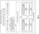
- Figure 2 illustrates an exemplary implementation of the processor-based system 100 of Figure 1 wherein the partitioned resource 104 comprises a system cache and the resource allocation agent 112 comprises a cache controller
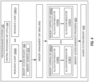
- Figure 4 illustrates an exemplary implementation of the processor-based system 100 of Figure 1 wherein the partitioned resource 104 comprises memory access bandwidth providers for a shared system memory and the resource allocation agent 112 comprises an MMU.
- Figures 3 and 5 are provided to illustrate how interpolation of the allocation indicators 114(0)-114(C), 114'(0)-114'(C) provides fine-grained QoS control in each of the aforementioned aspects.
- one aspect of the processor-based system 100 may provide a cache controller 200 corresponding to the resource allocation agent 112 of Figure 1 .
- Figure 2 further provides a system cache 202 that corresponds to the partitioned resource 104 of Figure 1 , and a plurality of cache partitions 204(0)-204(H) corresponding to the partitions 108(0)-108(P) of Figure 1 .
- disclosures herein regarding the resource allocation agent 112, the partitioned resource 104, and the partitions 108(0)-108(P) of Figure 1 apply to the cache controller 200, the system cache 202, and the cache partitions 204(0)-204(H), respectively, of Figure 2 .
- the system cache 202 may comprise a Level 1 (L1) cache, a Level 2 (L2) cache, a Level 3 (L3) cache, and/or a last-level cache, as non-limiting examples.
- the cache controller 200 Upon receiving a cache access request 206 comprising a memory address 208, the cache controller 200 assigns the cache access request 206 to one of the cache partitions 204(0)-204(H) (e.g., based on a hash of the memory address 208).
- the allocation indicators 114(0)-114(C), 114'(0)-114'(C) in the example of Figure 2 each comprise a way mask (not shown) providing a plurality of bit indicators (not shown).
- Each bit indicator of the allocation indicators 114(0)-114(C), 114'(0)-114'(C) corresponds to one way of one of the cache partitions 204(0)-204(H) of the system cache 202, and indicates whether the corresponding way has been allocated to the associated resource client 106(0)-106(C).
- the cache controller 200 uses the way masks provided by the allocation indicators 114(0)-114(C), 114'(0)-114'(C), the cache controller 200 allocates a portion of the assigned cache partition 204(0)-204(H) to carry out the cache access request 206 on behalf of the resource client 106(0)-106(C).
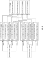
- Figure 3 provides a more detailed illustration of how the allocation indicators 114(0)-114(C), 114'(0)-114'(C) in the example of Figure 2 may be interpolated to provide fine-grained QoS control of the system cache 202 of Figure 2 .
- the allocation indicators 114(0)-114(3), 114'(0)-114'(3) provide way masks 300(0)-300(3), 300'(0)-300'(3), each of which is made up of 10 bits corresponding to the 10 ways.
- the allocation indicators 114(0)-114(3) represent the allocation of the cache partitions 204(0)-204(3), respectively, of the system cache 202 for the resource client 106(0).
- the allocation indicators 114'(0)-114'(3) similarly represent the allocation of the cache partitions 204(0)-204(3), respectively, of the system cache 202 for the resource client 106(C).
- system cache 202 in this example is made up of 10 ways, a conventional QoS mechanism would be able to allocate the system cache 202 only in increments of 10%. However, by interpolating the allocation indicators 114(0)-114(3), 114'(0)-114'(3) to determine aggregate allocations of the system cache 202 for the resource clients 106(0), 106(C), a higher allocation resolution can be attained.
- the system cache 202 may be allocated in increments as small as 2.5% (i.e., the number of ways (10) divided by the number of cache partitions 204(0)-204(3), in this example) by allocating one (1) way in one (1) of the cache partitions 204(0)-204(3), and allocating zero (0) ways allocated in the remaining cache partitions 204(0)-204(3). It is to be understood that the percentages discussed above are specific to the example of Figure 3 , and may vary in some aspects according to the number of ways and the number of cache partitions 204(0)-204(H).
- the allocation indicators 114(0) and 114(1) have the first five (5) bit indicators set to a value of one (1), indicating that the first five (5) ways (i.e., 50%) of the cache partitions 204(0) and 204(1), respectively, are allocated to the resource client 106(0).
- the allocation indicators 114(2) and 114(3) have the first six (6) bit indicators set to a value of one (1), indicating that the first six (6) ways (i.e., 60%) of the cache partitions 204(2) and 204(3), respectively, are allocated to the resource client 106(0).
- the total aggregate allocation of the system cache 202 for the resource client 106(0) is 55% (i.e., (50+50+60+60) / 4).
- the allocation indicators 114'(0) and 114'(1) have the last five (5) bit indicators set to a value of one (1), indicating that the last five (5) ways (i.e., 50%) of the cache partitions 204(0) and 204(1), respectively, are allocated to the resource client 106(C).
- the allocation indicators 114'(2) and 114'(3) have the last four (4) bit indicators set to a value of one (1), indicating that the last four (4) ways (i.e., 40%) of the cache partitions 204(2) and 204(3), respectively, are allocated to the resource client 106(C).
- the total aggregate allocation of the system cache 202 for the resource client 106(C) is therefore 45% (i.e., (50+50+40+40) / 4), an allocation that would not be possible using conventional QoS mechanisms with coarser resolutions.
- the processor-based system 100 of Figure 1 may provide an MMU 400 corresponding to the resource allocation agent 112 of Figure 1 , memory access bandwidth providers 402 that corresponds to the partitioned resource 104 of Figure 1 , and a plurality of memory controllers 404(0)-404(M) corresponding to the partitions 108(0)-108(P) of Figure 1 . Disclosures herein regarding the resource allocation agent 112, the partitioned resource 104, and the partitions 108(0)-108(P) of Figure 1 thus may apply to the MMU 400, the memory access bandwidth providers 402, and the memory controllers 404(0)-404(M), respectively, of Figure 4 .
- the processor-based system 100 also includes a shared system memory 406 that is accessible by the resource clients 106(0)-106(C) via the memory controllers 404(0)-404(M).
- the shared system memory 406 may comprise dynamic random access memory (DRAM), as a non-limiting example.
- the allocation indicators 114(0)-114(C), 114'(0)-114'(C) each comprise a memory stride value (not shown) that indicates a weight associated with requests for memory access bandwidth for the corresponding resource client 106(0)-106(C).
- the memory stride values are inversely proportional to the weight assigned to the requests for memory access bandwidth, such that a lower memory stride value indicates a higher weight.
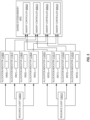
- Figure 5 illustrates in greater detail how fine-grained QoS control of the memory access bandwidth providers 402 of Figure 4 may be provided by interpolating the allocation indicators 114(0)-114(C), 114'(0)-114'(C).
- the allocation indicators 114(0)-114(3), 114'(0)-114'(3) provide memory stride values 500(0)-500(3), 500'(0)-500'(3) that have a size of four (4) bits and that indicate the relative weights assigned to requests for memory access bandwidth for the corresponding resource clients 106(0)-106(C) and the memory controllers 404(0)-404(3).
- the allocation indicators 114(0)-114(3) represent the allocations of the memory controllers 404(0)-404(3), respectively, of the memory access bandwidth providers 402 for the resource client 106(0), while the allocation indicators 114'(0)-114'(3) represent the allocations of the memory controllers 404(4)-404(3), respectively, of the memory access bandwidth providers 402 for the resource client 106(C).
- the memory access bandwidth providers 402 may be allocated in increments as small as 1.5625% (i.e., 1/16 divided by the number of memory controllers 404(0)-404(3), in this example) by selecting a memory stride value 500(0)-500(3), 500'(0)-500'(3) of one (1) for one (1) of the memory controllers 404(0)-404(M), and selecting a memory stride value 500(0)-500(3), 500'(0)-500'(3) of zero (0) in the remaining memory controllers 404(0)-404(3).
- the allocation indicators 114(0) and 114(1) have been assigned the memory stride values 500(0) and 500(1), respectively, each having a value of two (2).
- the allocation indicators 114(2) and 114(3) have been assigned the memory stride values 500(2) and 500(3), respectively, each of which has a value of one (1)
- the total aggregate memory stride value of the memory access bandwidth providers 402 for the resource client 106(0) is 1.5.
- the allocation indicators 114'(0) and 114'(1) have been assigned the memory stride values 500'(0) and 500'(1), respectively, each having a value of four (4), while the allocation indicators 114'(2) and 114'(3) have been assigned the memory stride values 500'(2) and 500'(3), respectively, each having a value of three (3).
- the total aggregate memory stride value of the memory access bandwidth providers 402 for the resource client 106(C) is therefore 3.5.
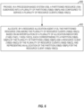
- Figure 6 illustrates exemplary operations of the processor-based system 100 and the resource allocation agent 112 of Figure 1 for providing fine-grained QoS control using interpolation for the partitioned resource 104.
- elements of Figure 1 are referenced in describing Figure 6 .
- operations begin with the processor-based system 100 providing the partitioned resource 104 subdivided into a plurality of partitions 108(0)-108(P) and configured to service a plurality of resource clients 106(0)-106(C) (block 600).
- the processor-based system 100 may be referred to herein as "a means for providing a partitioned resource subdivided into a plurality of partitions and configured to service a plurality of resource clients.”
- the resource allocation agent 112 (e.g., the cache controller 200 of Figure 2 and/or the MMU 400 of Figure 4 , as non-limiting examples) then allocates the partitioned resource 104 among the plurality of resource clients 106(0)-106(C) based on an interpolation of a plurality of allocation indicators 114(0)-114(C), 114'(0)-114'(C), each corresponding to a partition 108(0)-108(P) of the plurality of partitions 108(0)-108(P) and a resource client 106(0)-106(C) of the plurality of resource clients 106(0)-106(C), and representing an allocation of the partition 108(0)-108(P) for the resource client 106(0)-106(C) (block 602).
- the resource allocation agent 112 may be referred to herein as "a means for allocating the partitioned resource among the plurality of resource clients based on an interpolation of a plurality of allocation indicators, each corresponding to a partition of the plurality of partitions and a resource client of the plurality of resource clients, and representing an allocation of the partition for the resource client.”
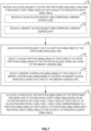
- Figure 7 To illustrate further exemplary operations of the resource allocation agent 112 of Figure 1 for receiving and assigning an access request, such as the access request 110 of Figure 1 , to the partitions 108(0)-108(P) of the partitioned resource 104, Figure 7 is provided. Elements of Figures 1-5 are referenced in describing Figure 7 , for the sake of clarity. Operations in Figure 7 begin with the resource allocation agent 112 receiving the access request 110 for the partitioned resource 104 from a resource client 106(0)-106(C) of the plurality of resource clients 106(0)-106(C) (block 700).
- operations of block 700 for receiving the access request 110 may be carried out by the cache controller 200, and may comprise receiving a cache access request 206 comprising a memory address 208 (block 702).
- aspects of the processor-based system 100 including the shared system memory 406 of Figure 4 may provide that operations of block 700 for receiving the access request 110 may be carried out by the MMU 400, and may comprise receiving a memory access request 408 comprising a memory address 410 (block 704).
- the access request 110 is assigned to a partition 108(0)-108(P) of the partitioned resource 104 (block 706).
- Operations of block 706 for assigning the access request 110 may comprise selecting a cache partition 204(0)-204(H) of the plurality of cache partitions 204(0)-204(H) of the system cache 202, based on a hash of the memory address 208 (block 708).
- operations of block 706 for assigning the access request 110 may comprise selecting a memory controller 404(0)-404(M) of the plurality of memory controllers 404(0)-404(M) to access the memory access bandwidth, based on a hash of the memory address 410 (block 710).
- the resource allocation agent 112 (e.g., the cache controller 200 of Figure 2 and/or the MMU 400 of Figure 4 , as non-limiting examples) allocates a portion of the partition 108(0)-108(P) of the partitioned resource 104 to the resource client 106(0)-106(C) based on an allocation indicator 114(0)-114(C), 114'(0)-114'(C) of the plurality of allocation indicators 114(0)-114(C), 114'(0)-114'(C), each corresponding to a partition 108(0)-108(P) of the plurality of partitions 108(0)-108(P) and a resource client 106(0)-106(C) of the plurality of resource clients 106(0)-106(C) (block 712).
- Providing fine-grained QoS control using interpolation for partitioned resources in processor-based systems may be provided in or integrated into any processor-based device.
- Examples include a set top box, an entertainment unit, a navigation device, a communications device, a fixed location data unit, a mobile location data unit, a global positioning system (GPS) device, a mobile phone, a cellular phone, a smart phone, a session initiation protocol (SIP) phone, a tablet, a phablet, a server, a computer, a portable computer, a mobile computing device, a wearable computing device (e.g., a smart watch, a health or fitness tracker, eyewear, etc.), a desktop computer, a personal digital assistant (PDA), a monitor, a computer monitor, a television, a tuner, a radio, a satellite radio, a music player, a digital music player, a portable music player, a digital video player, a video player, a digital
- PDA personal digital assistant
- Figure 8 illustrates an example of a processor-based system 800 that corresponds to the processor-based system 100 of Figures 1 , 2 , and 4 , and that can employ the resource allocation agent 112 illustrated in Figure 1 .
- the processor-based system 800 includes one or more CPUs 802, each including one or more processors 804.
- the CPU(s) 802 may have cache memory 806 that is coupled to the processor(s) 804 for rapid access to temporarily stored data, and that in some aspects may comprise the resource allocation agent 112 of Figure 1 .
- the CPU(s) 802 is coupled to a system bus 808 and can intercouple master and slave devices included in the processor-based system 800.
- the CPU(s) 802 communicates with these other devices by exchanging address, control, and data information over the system bus 808.
- the CPU(s) 802 can communicate bus transaction requests to a memory controller 810 as an example of a slave device.
- the memory controller 810 may correspond to the memory controllers 404(0)-404(M) of Figure 4 .
- Other master and slave devices can be connected to the system bus 808. As illustrated in Figure 8 , these devices can include a memory system 812, one or more input devices 814, one or more output devices 816, one or more network interface devices 818, and one or more display controllers 820, as examples.
- the memory system 812 may comprise the resource allocation agent 112 of Figure 1 .
- the input device(s) 814 can include any type of input device, including but not limited to input keys, switches, voice processors, etc.
- the output device(s) 816 can include any type of output device, including, but not limited to, audio, video, other visual indicators, etc.
- the network interface device(s) 818 can be any devices configured to allow exchange of data to and from a network 822.
- the network 822 can be any type of network, including, but not limited to, a wired or wireless network, a private or public network, a local area network (LAN), a wireless local area network (WLAN), a wide area network (WAN), a BLUETOOTH TM network, and the Internet.
- the network interface device(s) 818 can be configured to support any type of communications protocol desired.
- the memory system 812 can include one or more memory units 824(0)-824(N).
- the CPU(s) 802 may also be configured to access the display controller(s) 820 over the system bus 808 to control information sent to one or more displays 826.
- the display controller(s) 820 sends information to the display(s) 826 to be displayed via one or more video processors 828, which process the information to be displayed into a format suitable for the display(s) 826.
- the display(s) 826 can include any type of display, including, but not limited to, a cathode ray tube (CRT), a liquid crystal display (LCD), a plasma display, etc.
- DSP Digital Signal Processor
- ASIC Application Specific Integrated Circuit
- FPGA Field Programmable Gate Array
- a processor may be a microprocessor, but in the alternative, the processor may be any conventional processor, controller, microcontroller, or state machine.
- a processor may also be implemented as a combination of computing devices (e.g., a combination of a DSP and a microprocessor, a plurality of microprocessors, one or more microprocessors in conjunction with a DSP core, or any other such configuration).
- RAM Random Access Memory
- ROM Read Only Memory
- EPROM Electrically Programmable ROM
- EEPROM Electrically Erasable Programmable ROM
- registers a hard disk, a removable disk, a CD-ROM, or any other form of computer readable medium known in the art.
- An exemplary storage medium is coupled to the processor such that the processor can read information from, and write information to, the storage medium.
- the storage medium may be integral to the processor.
- the processor and the storage medium may reside in an ASIC.
- the ASIC may reside in a remote station.
- the processor and the storage medium may reside as discrete components in a remote station, base station, or server.
Landscapes
- Engineering & Computer Science (AREA)
- Theoretical Computer Science (AREA)
- Physics & Mathematics (AREA)
- General Engineering & Computer Science (AREA)
- General Physics & Mathematics (AREA)
- Software Systems (AREA)
- Memory System Of A Hierarchy Structure (AREA)
- Data Exchanges In Wide-Area Networks (AREA)
- Mobile Radio Communication Systems (AREA)
- Two-Way Televisions, Distribution Of Moving Picture Or The Like (AREA)
Claims (13)
- Ein prozessorbasiertes System (100) zum Vorsehen einer feinkörnigen Dienstgüte (Quality of Service bzw. QoS)-Steuerung von partitionierten Ressourcen (104), aufweisend:eine partitionierte Ressource (104), die in eine Vielzahl von Partitionen (108) unterteilt ist und konfiguriert ist zum Bedienen einer Vielzahl von Ressourcen-Clients (106),eine Vielzahl von Zuordnungsindikatoren (114), die jeweils einer Partition aus der Vielzahl von Partitionen und einem Ressourcen-Client aus der Vielzahl von Ressourcen-Clients entsprechen, wobei jeder aus der Vielzahl von Zuordnungsindikatoren einer einzigartigen Kombination aus einem Ressourcen-Client (106) und einer Partition (108) entspricht und eine Zuordnung der Partition (108) für den Ressourcen-Client (106) repräsentiert, undeinen Ressourcenzuordnungsagenten (112), der konfiguriert ist zum Zuordnen der partitionierten Ressource innerhalb der Vielzahl von Ressourcen-Clients, wobei der Ressourcenzuordnungsagent konfiguriert ist zum Empfangen einer Zugriffsanfrage (110) für die partitionierte Ressource von einem Ressourcen-Client (106) aus der Vielzahl von Ressourcen-Clients, zum Zuweisen der Zugriffsanfrage zu einer Partition der partitionierten Ressource und zum Zuordnen eines Teils der Partition der partitionierten Ressource zu dem Ressourcen-Client basierend auf einem Zuordnungsindikator (114) aus der Vielzahl von Zuordnungsindikatoren in Entsprechung zu der Partition und dem Ressourcen-Client (106).
- Prozessorbasiertes System nach Anspruch 1, wobei:die partitionierte Ressource einen Systemcache (202) aufweist,der Ressourcenzuordnungsagent eine Cache-Steuereinrichtung (200) aufweist,die Vielzahl von Partitionen eine Vielzahl von Cache-Partitionen des Systemcaches (202) aufweisen, unddie Vielzahl von Zuordnungsindikatoren (114) eine Vielzahl von Wegmasken aufweisen, die jeweils einen oder mehrere Cache-Wege einer entsprechenden Cache-Partition aus der Vielzahl von Cache-Partitionen (204), die zu einem entsprechenden Ressourcen-Client aus der Vielzahl von Ressourcen-Clients zugeordnet sind, angeben.
- Prozessorbasiertes System nach Anspruch 2, wobei der Ressourcenzuordnungsagent (112) konfiguriert ist zum:Empfangen der Zugriffsanfrage für die partitionierte Ressource von dem Ressourcen-Client aus der Vielzahl von Ressourcen-Clients mittels einer Konfiguration zum Empfangen einer Cachezugriffsanfrage (206) mit einer Speicheradresse (208), undZuweisen der Zugriffsanfrage zu der Partition der partitionierten Ressource mittels einer Konfiguration zum Auswählen einer Cache-Partition aus der Vielzahl von Cache-Partitionen des Systemcaches basierend auf einem Hash der Speicheradresse (208).
- Prozessorbasiertes System nach Anspruch 1, wobei:die partitionierte Ressource eine Vielzahl von Speicherzugriff-Bandbreitenbereitstellern (402) zu einem gemeinsamen Systemspeicher aufweist,der Ressourcenzuordnungsagent eine Speicherverwaltungseinheit (Memory Management Unit bzw. MMU) (400) aufweist,die Vielzahl von Partitionen eine Vielzahl von Speicher-Steuereinrichtungen (404), die konfiguriert sind zum Zugreifen auf den gemeinsamen Systemspeicher (406), aufweisen, unddie Vielzahl von Zuordnungsindikatoren eine Vielzahl von Speicher-Stridewerten (500) aufweisen, die jeweils ein relatives Gewicht für die Anwendung durch eine entsprechende Speicher-Steuereinrichtung aus der Vielzahl von Speicher-Steuereinrichtungen für jede Speicherzugriffsoperation für einen entsprechenden Ressourcen-Client aus der Vielzahl von Ressourcen-Clients angeben.
- Prozessorbasiertes System nach Anspruch 4, wobei der Ressourcenzuordnungsagent (112) konfiguriert ist zum:Empfangen der Zugriffsanfrage für die partitionierte Ressource von dem Ressourcen-Client aus der Vielzahl von Ressourcen-Clients mittels einer Konfiguration zum Empfangen einer Speicherzugriffsanfrage mit einer Speicheradresse, undZuweisen der Zugriffsanfrage zu der Partition der partitionierten Ressource mittels einer Konfiguration zum Auswählen einer Speicher-Steuereinrichtung aus der Vielzahl von Speicher-Steuereinrichtungen für einen Zugriff auf den gemeinsamen Systemspeicher basierend auf einem Hash der Speicheradresse.
- Prozessorbasiertes System nach Anspruch 1, das in einem integrierten Schaltkreis (Integrated Circuit bzw. IC) integriert ist.
- Prozessorbasiertes System nach Anspruch 1, das in einem Gerät integriert ist, das aus der Gruppe ausgewählt ist, die umfasst: eine Set-Top-Box, eine Unterhaltungseinheit, ein Navigationsgerät, ein Kommunikationsgerät, eine fix positionierte Dateneinheit, eine mobile Dateneinheit, ein GPS (Global Positioning System)-Gerät, ein Mobiltelefon, ein Zellulartelefon, ein Smartphone, ein SIP (Session Initiation Protocol)-Telefon, ein Tablet, ein Phablet, einen Server, einen Computer, einen tragbaren Computer, ein mobiles Rechengerät, ein tragbares Rechengerät (z.B. eine Smartwatch, einen Gesundheits- oder Fitnesstracker, eine Brille usw.), einen Desktop-Computer, einen PDA, einen Bildschirm, einen Computerbildschirm, ein Fernsehgerät, einen Tuner, ein Radio, ein Satellitenradio, ein Musikwiedergabegerät, ein digitales Musikwiedergabegerät, ein tragbares Musikwiedergabegerät, ein digitales Videowiedergabegerät, ein Videowiedergabegerät, ein DVD-Wiedergabegerät, ein tragbares digitales Videowiedergabegerät, ein Automobil, eine Fahrzeugkomponente, Avionik-Systeme, eine Drohne und einen Multicopter.
- Ein Verfahren zum Vorsehen einer feinkörnigen Dienstgüte (Quality of Service bzw. QoS)-Steuerung von partitionierten Ressourcen, aufweisend:
Zuordnen, durch einen Ressourcenzuordnungsagenten eines prozessorbasierten Systems, einer partitionierten Ressource, die in eine Vielzahl von Partitionen unterteilt ist, innerhalb einer Vielzahl von Ressourcen-Clients basierend auf einer Vielzahl von Zuordnungsindikatoren, wobei jeder aus der Vielzahl von Zuordnungsindikatoren einer einzigartigen Kombination eines aus der Vielzahl von Ressourcen-Clients (106) und einer aus der Vielzahl von Partitionen (108) entspricht und wobei das Zuordnen der partitionierten Ressource innerhalb einer Vielzahl von Ressourcen-Clients aufweist:Empfangen (700) einer Zugriffsanfrage (110) für die partitionierte Ressource (104) von einem Ressourcen-Client (106) aus der Vielzahl von Ressourcen-Clients,Zuweisen der Zugriffsanfrage zu einer Partition der partitionierten Ressource, undZuordnen eines Teils der Partition der partitionierten Ressource zu dem Ressourcen-Client basierend auf einem Zuordnungsindikator aus der Vielzahl von Zuordnungsindikatoren in Entsprechung zu der Partition und dem Ressourcen-Client. - Verfahren nach Anspruch 8, wobei:die partitionierte Ressource einen Systemcache (202) aufweist,der Ressourcenzuordnungsagent eine Cache-Steuereinrichtung (200) aufweist,die Vielzahl von Partitionen eine Vielzahl von Cache-Partitionen des Systemcaches (202) aufweisen, unddie Vielzahl von Zuordnungsindikatoren (114) eine Vielzahl von Wegmasken aufweisen, die jeweils einen oder mehrere Cache-Wege einer entsprechenden Cache-Partition aus der Vielzahl von Cache-Partitionen (204), die zu einem entsprechenden Ressourcen-Client aus der Vielzahl von Ressourcen-Clients zugeordnet sind, angeben.
- Verfahren nach Anspruch 8, wobei:das Empfangen der Zugriffsanfrage für die partitionierte Ressource von dem Ressourcen-Client aus der Vielzahl von Ressourcen-Clients das Empfangen einer Cachezugriffsanfrage (206) mit einer Speicheradresse (208) aufweist, unddas Zuweisen der Zugriffsanfrage zu der Partition der partitionierten Ressource das Auswählen einer Cache-Partition aus der Vielzahl von Cache-Partitionen des Systemcaches basierend auf einem Hash der Speicheradresse (208) aufweist.
- Verfahren nach Anspruch 8, wobei:die partitionierte Ressource eine Vielzahl von Speicherzugriff-Bandbreitenbereitstellern (402) zu einem gemeinsamen Systemspeicher aufweist,der Ressourcenzuordnungsagent eine Speicherverwaltungseinheit (Memory Management Unit bzw. MMU) (400) aufweist,die Vielzahl von Partitionen eine Vielzahl von Speicher-Steuereinrichtungen (404), die konfiguriert sind zum Zugreifen auf den gemeinsamen Systemspeicher (406), aufweisen, unddie Vielzahl von Zuordnungsindikatoren eine Vielzahl von Speicher-Stridewerten (500) aufweisen, die jeweils ein relatives Gewicht für die Anwendung durch eine entsprechende Speicher-Steuereinrichtung aus der Vielzahl von Speicher-Steuereinrichtungen für jede Speicherzugriffsoperation für einen entsprechenden Ressourcen-Client aus der Vielzahl von Ressourcen-Clients angeben.
- Verfahren nach Anspruch 11, wobei:das Empfangen (704) der Zugriffsanfrage (110) für die partitionierte Ressource von dem Ressourcen-Client aus der Vielzahl von Ressourcen-Clients das Empfangen einer Speicherzugriffsanfrage mit einer Speicheradresse aufweist, unddas Zuweisen (706) der Zugriffsanfrage (110) zu der Partition der partitionierten Ressource das Auswählen einer Speicher-Steuereinrichtung aus der Vielzahl von Speicher-Steuereinrichtungen basierend auf einem Hash der Speicheradresse aufweist.
- Ein nicht-transitorisches, computerlesbares Medium mit darauf gespeicherten computerausführbaren Befehlen, die bei einer Ausführung durch einen Prozessor das Verfahren gemäß einem der Ansprüche 8 bis 12 implementieren.
Applications Claiming Priority (2)
| Application Number | Priority Date | Filing Date | Title |
|---|---|---|---|
| US15/689,543 US10678690B2 (en) | 2017-08-29 | 2017-08-29 | Providing fine-grained quality of service (QoS) control using interpolation for partitioned resources in processor-based systems |
| PCT/US2018/045370 WO2019045954A1 (en) | 2017-08-29 | 2018-08-06 | REALIZING QUALIFIED SERVICE QUALITY CONTROL (QOS) USING SEGMENTED RESOURCE INTERPOLATION IN PROCESSOR-BASED SYSTEMS |
Publications (3)
| Publication Number | Publication Date |
|---|---|
| EP3676711A1 EP3676711A1 (de) | 2020-07-08 |
| EP3676711B1 true EP3676711B1 (de) | 2025-02-12 |
| EP3676711C0 EP3676711C0 (de) | 2025-02-12 |
Family
ID=63442777
Family Applications (1)
| Application Number | Title | Priority Date | Filing Date |
|---|---|---|---|
| EP18762422.6A Active EP3676711B1 (de) | 2017-08-29 | 2018-08-06 | Bereitstellung von feinkörniger dienstqualität (qos) mit interpolation für partitionierte ressourcen in prozessorbasierten systemen |
Country Status (6)
| Country | Link |
|---|---|
| US (1) | US10678690B2 (de) |
| EP (1) | EP3676711B1 (de) |
| CN (1) | CN111033480B (de) |
| SG (1) | SG11202000382RA (de) |
| TW (1) | TWI781201B (de) |
| WO (1) | WO2019045954A1 (de) |
Families Citing this family (9)
| Publication number | Priority date | Publication date | Assignee | Title |
|---|---|---|---|---|
| US11061728B2 (en) * | 2019-02-12 | 2021-07-13 | Western Digital Technologies, Inc. | Systems and methods for heterogeneous address space allocation |
| US10983919B2 (en) | 2019-09-25 | 2021-04-20 | Nvidia Corp. | Addressing cache slices in a last level cache |
| KR102720111B1 (ko) * | 2019-12-16 | 2024-10-22 | 현대자동차주식회사 | 차량용 멀티미디어 시스템 및 그를 위한 메모리 관리 방법 |
| CN111294247B (zh) * | 2020-05-13 | 2020-09-18 | 广东睿江云计算股份有限公司 | 一种存储区域的QoS分配方法及系统 |
| US11709711B2 (en) * | 2020-09-27 | 2023-07-25 | Advanced Micro Devices, Inc. | Allocation of memory access bandwidth to clients in an electronic device |
| US11880306B2 (en) | 2021-06-09 | 2024-01-23 | Ampere Computing Llc | Apparatus, system, and method for configuring a configurable combined private and shared cache |
| US12007896B2 (en) | 2021-06-09 | 2024-06-11 | Ampere Computing Llc | Apparatuses, systems, and methods for configuring combined private and shared cache levels in a processor-based system |
| WO2022261229A1 (en) * | 2021-06-09 | 2022-12-15 | Ampere Computing Llc | Apparatus and method for controlling allocations in a shared cache of a numa system |
| US11947454B2 (en) * | 2021-06-09 | 2024-04-02 | Ampere Computing Llc | Apparatuses, systems, and methods for controlling cache allocations in a configurable combined private and shared cache in a processor-based system |
Family Cites Families (21)
| Publication number | Priority date | Publication date | Assignee | Title |
|---|---|---|---|---|
| US6385638B1 (en) * | 1997-09-04 | 2002-05-07 | Equator Technologies, Inc. | Processor resource distributor and method |
| US6493800B1 (en) * | 1999-03-31 | 2002-12-10 | International Business Machines Corporation | Method and system for dynamically partitioning a shared cache |
| US20020108021A1 (en) * | 2001-02-08 | 2002-08-08 | Syed Moinul I. | High performance cache and method for operating same |
| US6871264B2 (en) * | 2002-03-06 | 2005-03-22 | Hewlett-Packard Development Company, L.P. | System and method for dynamic processor core and cache partitioning on large-scale multithreaded, multiprocessor integrated circuits |
| US7870301B2 (en) * | 2005-02-25 | 2011-01-11 | International Business Machines Corporation | System and method for modification of virtual adapter resources in a logically partitioned data processing system |
| US8464009B2 (en) * | 2008-06-04 | 2013-06-11 | Oracle America, Inc. | Method for memory interleave support with a ceiling mask |
| US8250332B2 (en) * | 2009-06-11 | 2012-08-21 | Qualcomm Incorporated | Partitioned replacement for cache memory |
| US8756608B2 (en) * | 2009-07-01 | 2014-06-17 | International Business Machines Corporation | Method and system for performance isolation in virtualized environments |
| US8543769B2 (en) * | 2009-07-27 | 2013-09-24 | International Business Machines Corporation | Fine grained cache allocation |
| US8745618B2 (en) * | 2009-08-25 | 2014-06-03 | International Business Machines Corporation | Cache partitioning with a partition table to effect allocation of ways and rows of the cache to virtual machine in virtualized environments |
| US8200902B2 (en) * | 2010-06-10 | 2012-06-12 | Arm Limited | Cache device for coupling to a memory device and a method of operation of such a cache device |
| KR101867286B1 (ko) | 2012-02-27 | 2018-06-15 | 삼성전자주식회사 | 작업 부하를 고려한 하드웨어 가속화 기반의 대규모 데이터의 분산 처리 장치 및 방법 |
| US9824013B2 (en) | 2012-05-08 | 2017-11-21 | Qualcomm Incorporated | Per thread cacheline allocation mechanism in shared partitioned caches in multi-threaded processors |
| US9098417B2 (en) * | 2012-12-13 | 2015-08-04 | Advanced Micro Devices, Inc. | Partitioning caches for sub-entities in computing devices |
| US10049048B1 (en) * | 2013-10-01 | 2018-08-14 | Facebook, Inc. | Method and system for using processor enclaves and cache partitioning to assist a software cryptoprocessor |
| US9563369B2 (en) | 2014-04-14 | 2017-02-07 | Microsoft Technology Licensing, Llc | Fine-grained bandwidth provisioning in a memory controller |
| US9612970B2 (en) * | 2014-07-17 | 2017-04-04 | Qualcomm Incorporated | Method and apparatus for flexible cache partitioning by sets and ways into component caches |
| US9678875B2 (en) * | 2014-11-25 | 2017-06-13 | Qualcomm Incorporated | Providing shared cache memory allocation control in shared cache memory systems |
| US9697126B2 (en) * | 2014-11-25 | 2017-07-04 | Qualcomm Incorporated | Generating approximate usage measurements for shared cache memory systems |
| US9824015B2 (en) * | 2015-05-29 | 2017-11-21 | Qualcomm Incorporated | Providing memory management unit (MMU) partitioned translation caches, and related apparatuses, methods, and computer-readable media |
| US9734070B2 (en) * | 2015-10-23 | 2017-08-15 | Qualcomm Incorporated | System and method for a shared cache with adaptive partitioning |
-
2017
- 2017-08-29 US US15/689,543 patent/US10678690B2/en active Active
-
2018
- 2018-07-27 TW TW107126114A patent/TWI781201B/zh active
- 2018-08-06 EP EP18762422.6A patent/EP3676711B1/de active Active
- 2018-08-06 WO PCT/US2018/045370 patent/WO2019045954A1/en not_active Ceased
- 2018-08-06 CN CN201880053700.3A patent/CN111033480B/zh active Active
- 2018-08-06 SG SG11202000382RA patent/SG11202000382RA/en unknown
Also Published As
| Publication number | Publication date |
|---|---|
| US10678690B2 (en) | 2020-06-09 |
| WO2019045954A1 (en) | 2019-03-07 |
| SG11202000382RA (en) | 2020-03-30 |
| CN111033480A (zh) | 2020-04-17 |
| TW201913394A (zh) | 2019-04-01 |
| US20190065374A1 (en) | 2019-02-28 |
| CN111033480B (zh) | 2024-06-18 |
| TWI781201B (zh) | 2022-10-21 |
| EP3676711A1 (de) | 2020-07-08 |
| EP3676711C0 (de) | 2025-02-12 |
Similar Documents
| Publication | Publication Date | Title |
|---|---|---|
| EP3676711B1 (de) | Bereitstellung von feinkörniger dienstqualität (qos) mit interpolation für partitionierte ressourcen in prozessorbasierten systemen | |
| JP7116047B2 (ja) | プロセッサベースシステムの異種メモリシステムの柔軟な管理を実現するためのメモリコントローラおよび方法 | |
| EP3224728B1 (de) | Bereitstellung einer zuweisungssteuerung gemeinsam genutzten cache-speicher in gemeinsamen cache-speichersystemen | |
| US9697126B2 (en) | Generating approximate usage measurements for shared cache memory systems | |
| EP3248095B1 (de) | Speicherressourcenverwaltung in virtualisierten umgebungen | |
| US11144368B2 (en) | Providing self-resetting multi-producer multi-consumer semaphores in distributed processor-based systems | |
| HK40018081A (en) | Providing fine-grained quality of service (qos) control using interpolation for partitioned resources in processor-based systems | |
| HK1234855A1 (en) | Generating approximate usage measurements for shared cache memory systems |
Legal Events
| Date | Code | Title | Description |
|---|---|---|---|
| STAA | Information on the status of an ep patent application or granted ep patent |
Free format text: STATUS: UNKNOWN |
|
| STAA | Information on the status of an ep patent application or granted ep patent |
Free format text: STATUS: THE INTERNATIONAL PUBLICATION HAS BEEN MADE |
|
| PUAI | Public reference made under article 153(3) epc to a published international application that has entered the european phase |
Free format text: ORIGINAL CODE: 0009012 |
|
| STAA | Information on the status of an ep patent application or granted ep patent |
Free format text: STATUS: REQUEST FOR EXAMINATION WAS MADE |
|
| 17P | Request for examination filed |
Effective date: 20200116 |
|
| AK | Designated contracting states |
Kind code of ref document: A1 Designated state(s): AL AT BE BG CH CY CZ DE DK EE ES FI FR GB GR HR HU IE IS IT LI LT LU LV MC MK MT NL NO PL PT RO RS SE SI SK SM TR |
|
| AX | Request for extension of the european patent |
Extension state: BA ME |
|
| DAV | Request for validation of the european patent (deleted) | ||
| DAX | Request for extension of the european patent (deleted) | ||
| STAA | Information on the status of an ep patent application or granted ep patent |
Free format text: STATUS: EXAMINATION IS IN PROGRESS |
|
| 17Q | First examination report despatched |
Effective date: 20220105 |
|
| GRAP | Despatch of communication of intention to grant a patent |
Free format text: ORIGINAL CODE: EPIDOSNIGR1 |
|
| STAA | Information on the status of an ep patent application or granted ep patent |
Free format text: STATUS: GRANT OF PATENT IS INTENDED |
|
| INTG | Intention to grant announced |
Effective date: 20240930 |
|
| GRAS | Grant fee paid |
Free format text: ORIGINAL CODE: EPIDOSNIGR3 |
|
| GRAA | (expected) grant |
Free format text: ORIGINAL CODE: 0009210 |
|
| STAA | Information on the status of an ep patent application or granted ep patent |
Free format text: STATUS: THE PATENT HAS BEEN GRANTED |
|
| AK | Designated contracting states |
Kind code of ref document: B1 Designated state(s): AL AT BE BG CH CY CZ DE DK EE ES FI FR GB GR HR HU IE IS IT LI LT LU LV MC MK MT NL NO PL PT RO RS SE SI SK SM TR |
|
| REG | Reference to a national code |
Ref country code: GB Ref legal event code: FG4D |
|
| REG | Reference to a national code |
Ref country code: CH Ref legal event code: EP |
|
| REG | Reference to a national code |
Ref country code: DE Ref legal event code: R096 Ref document number: 602018079085 Country of ref document: DE |
|
| REG | Reference to a national code |
Ref country code: IE Ref legal event code: FG4D |
|
| U01 | Request for unitary effect filed |
Effective date: 20250224 |
|
| U07 | Unitary effect registered |
Designated state(s): AT BE BG DE DK EE FI FR IT LT LU LV MT NL PT RO SE SI Effective date: 20250303 |
|
| PG25 | Lapsed in a contracting state [announced via postgrant information from national office to epo] |
Ref country code: RS Free format text: LAPSE BECAUSE OF FAILURE TO SUBMIT A TRANSLATION OF THE DESCRIPTION OR TO PAY THE FEE WITHIN THE PRESCRIBED TIME-LIMIT Effective date: 20250512 |
|
| PG25 | Lapsed in a contracting state [announced via postgrant information from national office to epo] |
Ref country code: PL Free format text: LAPSE BECAUSE OF FAILURE TO SUBMIT A TRANSLATION OF THE DESCRIPTION OR TO PAY THE FEE WITHIN THE PRESCRIBED TIME-LIMIT Effective date: 20250212 |
|
| PG25 | Lapsed in a contracting state [announced via postgrant information from national office to epo] |
Ref country code: ES Free format text: LAPSE BECAUSE OF FAILURE TO SUBMIT A TRANSLATION OF THE DESCRIPTION OR TO PAY THE FEE WITHIN THE PRESCRIBED TIME-LIMIT Effective date: 20250212 |
|
| PG25 | Lapsed in a contracting state [announced via postgrant information from national office to epo] |
Ref country code: IS Free format text: LAPSE BECAUSE OF FAILURE TO SUBMIT A TRANSLATION OF THE DESCRIPTION OR TO PAY THE FEE WITHIN THE PRESCRIBED TIME-LIMIT Effective date: 20250612 Ref country code: NO Free format text: LAPSE BECAUSE OF FAILURE TO SUBMIT A TRANSLATION OF THE DESCRIPTION OR TO PAY THE FEE WITHIN THE PRESCRIBED TIME-LIMIT Effective date: 20250512 |
|
| PG25 | Lapsed in a contracting state [announced via postgrant information from national office to epo] |
Ref country code: HR Free format text: LAPSE BECAUSE OF FAILURE TO SUBMIT A TRANSLATION OF THE DESCRIPTION OR TO PAY THE FEE WITHIN THE PRESCRIBED TIME-LIMIT Effective date: 20250212 |
|
| PG25 | Lapsed in a contracting state [announced via postgrant information from national office to epo] |
Ref country code: GR Free format text: LAPSE BECAUSE OF FAILURE TO SUBMIT A TRANSLATION OF THE DESCRIPTION OR TO PAY THE FEE WITHIN THE PRESCRIBED TIME-LIMIT Effective date: 20250513 |
|
| U20 | Renewal fee for the european patent with unitary effect paid |
Year of fee payment: 8 Effective date: 20250710 |
|
| PG25 | Lapsed in a contracting state [announced via postgrant information from national office to epo] |
Ref country code: SM Free format text: LAPSE BECAUSE OF FAILURE TO SUBMIT A TRANSLATION OF THE DESCRIPTION OR TO PAY THE FEE WITHIN THE PRESCRIBED TIME-LIMIT Effective date: 20250212 |
|
| PGFP | Annual fee paid to national office [announced via postgrant information from national office to epo] |
Ref country code: GB Payment date: 20250710 Year of fee payment: 8 |
|
| PG25 | Lapsed in a contracting state [announced via postgrant information from national office to epo] |
Ref country code: CZ Free format text: LAPSE BECAUSE OF FAILURE TO SUBMIT A TRANSLATION OF THE DESCRIPTION OR TO PAY THE FEE WITHIN THE PRESCRIBED TIME-LIMIT Effective date: 20250212 |
|
| PGFP | Annual fee paid to national office [announced via postgrant information from national office to epo] |
Ref country code: IE Payment date: 20250709 Year of fee payment: 8 |
|
| PG25 | Lapsed in a contracting state [announced via postgrant information from national office to epo] |
Ref country code: SK Free format text: LAPSE BECAUSE OF FAILURE TO SUBMIT A TRANSLATION OF THE DESCRIPTION OR TO PAY THE FEE WITHIN THE PRESCRIBED TIME-LIMIT Effective date: 20250212 |