EP3676700B1 - Efficient direct convolution using simd instructions - Google Patents
Efficient direct convolution using simd instructions Download PDFInfo
- Publication number
- EP3676700B1 EP3676700B1 EP18779130.6A EP18779130A EP3676700B1 EP 3676700 B1 EP3676700 B1 EP 3676700B1 EP 18779130 A EP18779130 A EP 18779130A EP 3676700 B1 EP3676700 B1 EP 3676700B1
- Authority
- EP
- European Patent Office
- Prior art keywords
- vector
- vectors
- convolution
- data
- source
- Prior art date
- Legal status (The legal status is an assumption and is not a legal conclusion. Google has not performed a legal analysis and makes no representation as to the accuracy of the status listed.)
- Active
Links
- 239000013598 vector Substances 0.000 claims description 495
- 238000000034 method Methods 0.000 claims description 51
- 238000013527 convolutional neural network Methods 0.000 claims description 4
- 238000000605 extraction Methods 0.000 claims 7
- 230000015654 memory Effects 0.000 description 31
- 238000010586 diagram Methods 0.000 description 14
- 238000013459 approach Methods 0.000 description 10
- 238000012545 processing Methods 0.000 description 10
- 238000013528 artificial neural network Methods 0.000 description 9
- 238000010801 machine learning Methods 0.000 description 7
- 230000008569 process Effects 0.000 description 4
- 241000613118 Gryllus integer Species 0.000 description 3
- 238000007667 floating Methods 0.000 description 3
- 230000008520 organization Effects 0.000 description 3
- 230000008901 benefit Effects 0.000 description 2
- 230000005291 magnetic effect Effects 0.000 description 2
- 238000013507 mapping Methods 0.000 description 2
- 239000011159 matrix material Substances 0.000 description 2
- 208000009119 Giant Axonal Neuropathy Diseases 0.000 description 1
- 239000000872 buffer Substances 0.000 description 1
- 238000004891 communication Methods 0.000 description 1
- 230000000694 effects Effects 0.000 description 1
- 238000005516 engineering process Methods 0.000 description 1
- 238000001914 filtration Methods 0.000 description 1
- 230000006870 function Effects 0.000 description 1
- 201000003382 giant axonal neuropathy 1 Diseases 0.000 description 1
- 230000007246 mechanism Effects 0.000 description 1
- 238000012986 modification Methods 0.000 description 1
- 230000004048 modification Effects 0.000 description 1
- 210000002569 neuron Anatomy 0.000 description 1
- 230000003287 optical effect Effects 0.000 description 1
- 230000002093 peripheral effect Effects 0.000 description 1
- 238000002360 preparation method Methods 0.000 description 1
- 230000000306 recurrent effect Effects 0.000 description 1
- 239000004065 semiconductor Substances 0.000 description 1
- 230000003068 static effect Effects 0.000 description 1
- 238000012549 training Methods 0.000 description 1
Images


Classifications
-
- G—PHYSICS
- G06—COMPUTING; CALCULATING OR COUNTING
- G06F—ELECTRIC DIGITAL DATA PROCESSING
- G06F9/00—Arrangements for program control, e.g. control units
- G06F9/06—Arrangements for program control, e.g. control units using stored programs, i.e. using an internal store of processing equipment to receive or retain programs
- G06F9/30—Arrangements for executing machine instructions, e.g. instruction decode
- G06F9/30003—Arrangements for executing specific machine instructions
- G06F9/30007—Arrangements for executing specific machine instructions to perform operations on data operands
- G06F9/30036—Instructions to perform operations on packed data, e.g. vector, tile or matrix operations
-
- G—PHYSICS
- G06—COMPUTING; CALCULATING OR COUNTING
- G06F—ELECTRIC DIGITAL DATA PROCESSING
- G06F17/00—Digital computing or data processing equipment or methods, specially adapted for specific functions
- G06F17/10—Complex mathematical operations
- G06F17/15—Correlation function computation including computation of convolution operations
-
- G—PHYSICS
- G06—COMPUTING; CALCULATING OR COUNTING
- G06F—ELECTRIC DIGITAL DATA PROCESSING
- G06F9/00—Arrangements for program control, e.g. control units
- G06F9/06—Arrangements for program control, e.g. control units using stored programs, i.e. using an internal store of processing equipment to receive or retain programs
- G06F9/30—Arrangements for executing machine instructions, e.g. instruction decode
- G06F9/30003—Arrangements for executing specific machine instructions
- G06F9/30007—Arrangements for executing specific machine instructions to perform operations on data operands
- G06F9/3001—Arithmetic instructions
-
- G—PHYSICS
- G06—COMPUTING; CALCULATING OR COUNTING
- G06F—ELECTRIC DIGITAL DATA PROCESSING
- G06F9/00—Arrangements for program control, e.g. control units
- G06F9/06—Arrangements for program control, e.g. control units using stored programs, i.e. using an internal store of processing equipment to receive or retain programs
- G06F9/30—Arrangements for executing machine instructions, e.g. instruction decode
- G06F9/30003—Arrangements for executing specific machine instructions
- G06F9/30007—Arrangements for executing specific machine instructions to perform operations on data operands
- G06F9/30032—Movement instructions, e.g. MOVE, SHIFT, ROTATE, SHUFFLE
-
- G—PHYSICS
- G06—COMPUTING; CALCULATING OR COUNTING
- G06F—ELECTRIC DIGITAL DATA PROCESSING
- G06F9/00—Arrangements for program control, e.g. control units
- G06F9/06—Arrangements for program control, e.g. control units using stored programs, i.e. using an internal store of processing equipment to receive or retain programs
- G06F9/30—Arrangements for executing machine instructions, e.g. instruction decode
- G06F9/38—Concurrent instruction execution, e.g. pipeline, look ahead
- G06F9/3885—Concurrent instruction execution, e.g. pipeline, look ahead using a plurality of independent parallel functional units
- G06F9/3887—Concurrent instruction execution, e.g. pipeline, look ahead using a plurality of independent parallel functional units controlled by a single instruction for multiple data lanes [SIMD]
-
- G—PHYSICS
- G06—COMPUTING; CALCULATING OR COUNTING
- G06N—COMPUTING ARRANGEMENTS BASED ON SPECIFIC COMPUTATIONAL MODELS
- G06N3/00—Computing arrangements based on biological models
- G06N3/02—Neural networks
- G06N3/04—Architecture, e.g. interconnection topology
- G06N3/045—Combinations of networks
-
- G—PHYSICS
- G06—COMPUTING; CALCULATING OR COUNTING
- G06N—COMPUTING ARRANGEMENTS BASED ON SPECIFIC COMPUTATIONAL MODELS
- G06N3/00—Computing arrangements based on biological models
- G06N3/02—Neural networks
- G06N3/06—Physical realisation, i.e. hardware implementation of neural networks, neurons or parts of neurons
- G06N3/063—Physical realisation, i.e. hardware implementation of neural networks, neurons or parts of neurons using electronic means
-
- G—PHYSICS
- G06—COMPUTING; CALCULATING OR COUNTING
- G06N—COMPUTING ARRANGEMENTS BASED ON SPECIFIC COMPUTATIONAL MODELS
- G06N3/00—Computing arrangements based on biological models
- G06N3/02—Neural networks
- G06N3/08—Learning methods
Definitions
- This disclosure relates generally to digital signal processing, machine learning and neural networks, and more particularly to systems and methods for filtering of signals using convolution operations.
- a convolution is a weighted sum of an input value and its immediate neighboring values in a data set producing an output value of an output data set.
- These data sets may be single dimensional or multi-dimensional with corresponding data organization determining the values which are immediate neighbors of the input value.
- the weighting values of the convolution are specified in a convolution kernel where the kernel possesses the same number of dimensions as the input and output data sets. Convolution operations are useful in great variety of signal processing applications and are integral to the operation of many aspects of deep neural networks.
- Convolutions may be used pervasively in machine learning applications. In this context it is common to apply convolutions on a single data set using many, small convolution kernels. As a result, convolutions are often a computationally intensive portion of machine learning applications so an efficient means of performing convolution operations is of increasingly great value.
- convolution lowering involves converting the convolution operation into an equivalent computational process that can be solved by optimized dense linear algebra. This allows the use of optimized General Matrix Multiply (GEMM) routines which are adept at leveraging inherent reuse of data, minimizing off-chip bandwidth needs, and subdividing computation that can be spread across many cores. There are also significant disadvantages to this approach, convolution lowering adds additional processor overhead and increases data size significantly. Increased data size makes caching difficult and increases off-chip bandwidth usage, leading to solutions that prefer expensive, high performance memory in lieu of caching and conventional memory technologies.
- GEMM General Matrix Multiply
- a second approach is to perform the convolution in frequency domain. This requires the input data set and the convolution kernel to each be converted into frequency domain, the two converted data sets multiplied together, and an inverse frequency transform applied to the product.
- This approach offers similar advantages and disadvantages to convolution lowering, the multiplication operation may again be implemented by GEMM routines but additional computational overhead is added and memory footprint may increase dramatically for small kernel sizes.
- convolution in frequency domain is unappealing due to the requirement to convert the many, small kernels to frequency domain.
- a third approach commonly referred to as "direct convolution" applies convolution filters directly to data in time or spatial domain.
- This approach avoids the additional computational overhead and memory growth of the previous approaches but suffers from much lower processor utilization, less parallelism and exploitation of reuse, or hardware that is dedicated only to solving convolutions.
- such hardware does not leverage existing resources of conventional hardware and is nontrivial to program and optimize for a given deep neural network.
- US 2017/024218 A1 relates to a sliding window operation in which a SIMD lane is configured to perform a sliding window operation on first input data elements in a lane of a first register and second input data elements in a lane of a second register.
- EP 3 093 757 A2 relates to a multi-dimensional sliding window operation for a vector processor.
- US 2015/086134 A1 relates to a low power programmable image processor including a load and store unit, a shift register unit, and a mapping unit to perform convolution operations, wherein the shift register unit is configured to load and store at least a portion of the image; the mapping unit is configured to generate a number of shifted versions of image pixel data and corresponding stencil data from the portion of the image pixel data, and concurrently perform one or more operations on each image pixel value in the shifted versions of the portion of the image pixel data and a corresponding stencil value in the corresponding stencil data.
- a processor may include vector instructions providing parallel execution lanes for each instruction executed, such as in a Single Instruction Multiple Data (SIMD) micro-architecture.
- SIMD Single Instruction Multiple Data
- This type of micro-architecture may provide higher throughput for certain applications than single-lane or general-purpose micro-architectures. While general-purpose micro-architectures operate on a single lane of data contained in registers, SIMD micro-architectures operate on data contained in vectors composed of multiple lanes of independent data.
- SIMD source vectors are loaded, one source vector aligned with the destination vector to be computed, one or more source vectors including left-partial data with respect to the destination vector, and one or more source vectors including right-partial data with respect to the destination vector.
- Each of these source vectors is multiplied with respective convolution coefficient vectors and added to accumulator vector. Once all source vectors have been processed, the accumulator vector is written to the destination vector.
- the convolution to be performed may be a multi-dimensional convolution.
- multiple accumulator vectors may be computed simultaneously using the same loaded source vectors.
- the various source vectors may be multiplied with other convolution coefficient vectors corresponding to other dimensions of the convolution kernel and the multiple accumulator vectors may not be written until all source vectors for a given destination vector have been processed.
- a SIMD instruction may be provided to extract unaligned SIMD vectors from pairs of aligned SIMD vectors.
- the aligned source vector as well as the plurality of shifted source vectors may be loaded from a common data source.
- a SIMD instruction may be provided to perform a SIMD Scalar Multiply-and-Add operation where each lane of a data vector is multiplied by a scalar quantity and added to a respective lane of a base vector.
- convolution operations may be performed on multiple input data sets simultaneously by computing partial-resolution output data sets using pre-interleaved source data.
- a SIMD instruction may be provided to perform a de-interlacing operation on computed data vectors to extract partial-resolution output data vectors.
- the various embodiments disclosed transform the computation of direct convolutions from operations traditionally limited by memory bandwidth to ones that fully exploit the computational resources and bandwidth of cache and memory subsystems while requiring only the main CPU, and while these embodiments are especially suited to direct convolution computations, it should be noted that they may apply more generally to a variety of computational tasks, for example to general parallel traversal techniques.
- circuits, or other components may be described as “configured to” perform a task or tasks.
- “configured to” is a broad recitation of structure generally meaning “having circuitry that" performs the task or tasks during operation.
- the unit/circuit/component can be configured to perform the task even when the unit/circuit/component is not currently on.
- the circuitry that forms the structure corresponding to "configured to” may include hardware circuits.
- various units/circuits/components may be described as performing a task or tasks, for convenience in the description. Such descriptions should be interpreted as including the phrase "configured to.”
- Deep neural networks have become increasingly important in solving a wide range of generic problems in conjunction with large data sets. These networks, however, spend a significant amount of processing time in convolutions and matrix multiplications, with processing time more than doubled per pass during the training phase in order to update neuron weights. A large number of passes may further be needed for slowly converging networks. As a result, efficient convolution computations are increasingly important.
- FIG. 1 provides a block diagram of one embodiment of a computer system.
- Computer System 100 includes a Processor 110, a Memory 120, and a Mass Storage Device 140 attached to an IO Bus 130.
- the Processor 110 includes an Execution Core 112, including a Register File 114, coupled to a Cache 116.
- Computer System 100 may not include the Mass Storage Device 140 while multiple processors similar to the Processor 110 may be included.
- a single Cache 116 is shown internal to the Processor 110, a hierarchical cache including multiple levels both internal and external to the Processor 110 may be present.
- Computer System 100 may also include graphics processors, user-interface devices, network cards, and/or other peripheral devices that are coupled to Processor 110 using the IO Bus 130, a network, or other communication channel.
- the Processor 110 may be representative of a general-purpose processor that performs computational operations.
- the Processor 110 may be a central processing unit (CPU) such as a microprocessor, microcontroller, application-specific integrated circuit (ASIC), or field-programmable gate array (FPGA).
- CPU central processing unit
- ASIC application-specific integrated circuit
- FPGA field-programmable gate array
- the Processor 110 may be a standalone component or may be integrated with other components (e.g. other processors, or other components in a system on a chip (SOC) or FPGA) or may be a component in a multichip module (MCM) with other components.
- the Processor 110 may include one or more mechanisms for vector processing (e.g., vector execution units).
- the Processor 110 may include an Execution Core 112.
- the Execution Core 112 may be configured to execute instructions defined in an instruction set architecture implemented by the Processor 110.
- the Execution Core 112 may have various micro-architectural features and implementation features, as desired.
- the Execution Core 112 may include superscalar or scalar implementations.
- the Execution Core 112 may include in-order or out-of-order implementations, and speculative or non-speculative implementations.
- the Execution Core 112 may include any combination of the above features.
- the implementations may include microcode in some embodiments.
- the Execution Core 112 may also include a variety of execution units, each execution unit configured to execute operations of various types (e.g.
- the Execution Core 112 may include different numbers pipeline stages and various other performance-enhancing features such as branch prediction.
- the Execution Core 112 may include one or more of instruction decode units, schedulers or reservations stations, reorder buffers, memory management units, I/O interfaces, etc.
- the Register File 114 may include a set of registers that may be used to store operands for various instructions.
- the Register File 114 may include registers of various data types, based on the type of operand the Execution Core 112 is configured to store in the registers (e.g. integer, floating point, multimedia, vector, etc.).
- the Register File 114 may include architected registers (i.e. those registers that are specified in the instruction set architecture implemented by the Processor 110). Alternatively or in addition, the Register File 114 may include physical registers (e.g. if register renaming is implemented in the Execution Core 112).
- the Cache 116 may be illustrative of any caching structure.
- the Cache 116 may be implemented as a Harvard architecture (separate instruction cache for instruction fetching and data cache for data read/write by execution units for memory-referencing operations), as a shared instruction and data cache, etc.
- load/store execution units may be provided to execute the memory-referencing operations.
- An instruction may be an executable entity defined in an instruction set architecture implemented by the Processor 110.
- instruction set architectures There are a variety of instruction set architectures (e.g. the x86 architecture original developed by Intel, ARM from ARM Holdings, Power and PowerPC from IBM/Motorola, etc.).
- Each instruction is defined in the instruction set architecture, including its coding in memory, its operation, and its effect on registers, memory locations, and/or other processor state.
- a given implementation of the instruction set architecture may execute each instruction directly, although its form may be altered through decoding and other manipulation in the processor hardware.
- Another implementation may decode at least some instructions into multiple instruction operations for execution by the execution units in the Processor 110. Some instructions may be microcoded in some embodiments.
- the mass-storage device 110, Memory 120 and Cache 116 are storage devices that collectively form a memory hierarchy that stores data and instructions for Processor 110. More particularly, the mass-storage device 110 may be a high-capacity, non-volatile memory, such as a disk drive or a large flash memory unit with a long access time, while Cache 116 and Memory 120 may be smaller but with shorter access times. These faster semiconductor memories store copies of frequently used data. Memory 120 may be representative of a memory device in the dynamic random access memory (DRAM) family of memory devices. The size of Memory 120 is typically larger than Cache 116 whereas Cache 116 is typically implemented using smaller devices in the static random access memories (SRAM) family of devices. In some embodiments, cache 116, Memory 120 and mass-storage device 110 are shared between one or more processors in Computer System 100.
- DRAM dynamic random access memory
- SRAM static random access memories
- non-transitory computer-readable storage device may be any device or storage medium that can store code and/or data for use by a computer system (e.g., Computer System 100).
- a non-transitory computer-readable storage device includes, but is not limited to, volatile memory, non-volatile memory, magnetic and optical storage devices such as disk drives, magnetic tape, compact discs (CDs), digital versatile discs or digital video discs (DVDs), or other media capable of storing computer-readable media now known or later developed.
- mass-storage device 110, Memory 120 and Cache 116 are all examples of non-transitory computer readable storage media.
- the Execution Core 112 may be configured to execute vector instructions.
- the vector instructions may be defined as single instruction-multiple-data (SIMD) instructions in the classical sense, in that they may define the same operation to be performed on multiple data elements in parallel.
- SIMD single instruction-multiple-data
- the data elements operated upon by an instance of an instruction may be referred to as a vector and are organized in data lanes. These data elements may contain data of various, multi-bit data types based on the type of operand the Execution Core 112 is configured to store in the registers (e.g. integer, floating point, multimedia, vector, etc.).
- registers e.g. integer, floating point, multimedia, vector, etc.
- vectors in the disclosure are represented as including eight data lanes, although it should be understood that this is not intended to limit the disclosure to this particular vector organization.
- vectors may be configured provide any number of data lanes.
- there may be 32 vector registers in the vector register file and each vector register may include 128 bits.
- vector lengths may be implemented as powers of two (e.g., two, four, eight, etc.). However, in some embodiments, vector lengths need not be powers of two.
- embodiments which implement register renaming may include any number of physical registers that may be allocated to architected vector registers. Architected registers may be registers that are specifiable as operands in vector instructions.
- a convolution is a weighted sum of an input value and its immediate neighboring values in a data set producing an output value of an output data set.
- These data sets may be one-dimensional or multi-dimensional with corresponding data organization determining the values which are immediate neighbors of the input value.
- the weighting values of the convolution are specified in a convolution kernel where the kernel possesses the same number of dimensions as the input and output data sets.
- FIG. 2A depicts a one-dimensional convolution operation 225.
- the data element s2 of Source Data 200 is to be convolved with a three-element Convolution Kernel 210 to produce data element o2 in the Output Data 220.
- data elements s1 and s3 of Source Data 200 are required for the convolution as immediate left and right neighbors of the data element s2.
- FIG. 2B depicts a two dimensional convolution operation 275.
- the data element s5 of Source Data 250 is to be convolved with a 3x3-element Convolution Kernel 260 to produce data element o5 in the Output Data 270.
- data elements s1-s4 and s6-s9 of Source Data 250 are required for the convolution as immediate neighbors, left, right, above and below, of the data element s2.
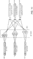
- FIG. 3 illustrates a method of pre-shifting of source data sets according to some embodiments.
- FIG. 3 shows Left Shifted Data 310 corresponding to a data set where vector alignment has been shifted left one data lane and Right Shifted Data 320 corresponding to a data set where vector alignment has been shifted right one data lane.
- the three data sets, 300, 310 and 320 correspond to a convolution operation using a convolution kernel consisting of three columns.
- Such convolutions may be one-dimensional convolutions or multi-dimensional convolutions.
- the pre-shifting of data sets in not limited to convolutions of three columns.
- a five column convolution may have a total of five source data sets, the three shown in FIG.3 , 300, 310 and 320, as well as a double left-shifted data set and a double right-shifted data set.
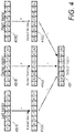
- FIG. 4 illustrates the computation of a convolution output vector using a one-dimensional three element convolution kernel given pre-shifted source vectors.
- the pre-shifted source vectors may be loaded from pre-shifted data sets such as illustrated in FIG. 3 in some embodiments but may also be loaded using a variety of other methods in other embodiments.
- the Kernel Vectors 410A, 410B and 410C are vector representations of the Convolution Kernel 210 of FIG. 2A .
- Each Kernel Vector is comprised of a respective Convolution Kernel weighting value replicated into all data lanes of the Kernel Vector.
- the Kernel Vector 410B corresponds to the middle weighting value of the Convolution Kernel 210 and thus has the weighting value k2 replicated into all its data lanes.
- the Output Vector 420 is thus the sum of the source vectors 400 multiplied by their respective kernel vectors 410.
- the convolution computation illustrated in FIG. 4 is not limited performing convolutions involving only three kernel columns but may be expanded to implement any number of kernel columns.
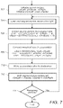
- FIG. 5 is a flow diagram demonstrating a one dimensional, three element convolution of multiple data vectors according to some embodiments.
- the method begins with step 502 which initializes three kernel vectors, vKLeft, vKCenter and vKRight corresponding to Kernel Vectors 410 of FIG. 4 . As these vectors remain constant for the duration of the convolution operation, they may be loaded only once.
- step 504 loads the aligned and shifted source vectors vLeft, vCenter, and vRight corresponding to the Vectors 400 in FIG. 4 .
- vLeft, vCenter, and vRight may be loaded from pre-shifted data sets such as those shown in FIG. 3 while in other embodiments they may be loaded through other means.
- step 506 the Multiply-and-Add vector instruction is represented by the MADD operation which takes three operands: the first operand is the base vector, the second operand is the source vector, and the third operand is the kernel vector.
- the MADD operation multiplies the second and third operands then adds the product to the first operand and returns a result vector.
- the base vector specified, vZero corresponds to a vector containing 0 values in all data lanes and is common to many SIMD architectures.
- the vector accumulator vAcc may first be initialized by an alternative means.
- the base vector specified is the accumulator vAcc.
- the three source vectors, vLeft, vCenter and vRight, are multiplied by their respective kernel vectors, vKLeft, vKCenter, and vKRight, and added to the accumulator vAcc.
- step 508 the accumulator vector is written to the destination address.
- the number of remaining vectors is checked in step 510 and the process continues at step 504 until all vectors have been generated.
- FIG. 5 performs a one-dimensional convolution with a three element kernel
- the embodiment is not intended to be limited to three elements but may include a variety of kernel widths.
- the embodiment on FIG. 5 implements an efficient computation of weighted sums, it relies on pre-shifted source data, such as those shown in FIG. 3 , and for wider kernel widths, the use of these pre-shifted data sets results in larger demands on memory and off-chip bandwidth. For this reason, a vector instruction to derive the shifted source data is disclosed in FIG. 6A . The use of this vector instruction, when combined with the embodiment of FIG. 5 , minimizes off-chip bandwidth requirements, particularly with wider kernel widths.
- an Extract vector instruction may be used to generate the shifted data vectors required for the convolution computations using a pair of aligned source vectors.
- the use of the Extract vector instruction allows the of source data as originally supplied for a convolution operation, thus enabling efficient use of memory and cache bandwidth.
- FIG. 6A illustrates an example of such an Extract vector instruction 620.
- two consecutive source vectors, 600A and 600B are concatenated and subset of the resulting double-width vector is extracted starting at an offset data lane specified by Shift 605 to produce the Output Vector 610.
- Output Width 615 may be specified which allows for the Output Vector to contain less than the full vector width of output data lanes. In this case, the rightmost lanes of the Output Vector 610 will contain zero.
- a vector width of eight data lanes is shown with a Shift 605 value of four and an Output Width 615 value of six.
- various embodiments of convolution operations may load shifted source vectors for a wide variety of kernel widths using only three aligned source vectors, the center aligned vector and an aligned vector to the immediate left and immediate right of the center aligned vector.
- FIG. 6B illustrates the loading of source vectors for a one dimensional, three element convolution such as shown in FIG. 4 .
- Three aligned source vectors are loaded, a center source vector 625B, a source vector immediately to the left of the center vector 625A, and a source vector immediately to the right of the center vector 625C.
- An Extract Left operation 630 is performed using the left and center source vectors, 625A and 625B, and the Extract vector instruction 620 of FIG. 6A using a shift value of equal to the number of data lanes in the vector, eight in the example, minus one. This operation results in the Left Vector 650.
- an Extract Right operation 640 is performed using the center and right source vectors, 625B and 625C, and the Extract vector instruction 620 of FIG. 6A using a shift value of one. This operation results in the Right Vector 670.
- the set of vectors 650, 660 and 670 may then be used in a convolution such as illustrated in FIG. 5 .
- the method illustrated in FIG. 6B is not intended to be limited to a three element convolution operation but may be used to generate vectors required to perform convolutions for a variety of kernel widths, often without the need to load additional source vectors 625 beyond those illustrated in FIG. 6B .
- use of the Extract vector instruction 620 eliminates the need for pre-shifted data such as illustrated in FIG. 3 , this eliminating growth in data size for the convolution operation.
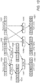
- FIG. 7 is a flow diagram demonstrating a one dimensional, three element convolution of multiple data vectors using the Extract method of FIG. 6B according to some embodiments.
- the convolution of FIG.7 minimizes the number of loads and stores of vector data to main memory and uses the original source data without and precomputing of vector data. Furthermore, the sequence of loads and stores to main memory enables high performance of system caches, resulting in a high performance convolution implementation that balances computational demands with cache and memory bandwidth.
- step 702 initializes three kernel vectors, vKLeft, vKCenter and vKRight corresponding to Kernel Vectors 410 of FIG. 4 . As these vectors remain constant for the duration of the convolution operation, they may be loaded only once. Additionally, the left-aligned source vector, vSrcLeft, is initialized and the first source vector is loaded into vCenter.
- step 704 loads the right-aligned source vector vSrcRight.
- step 704 loads the right-aligned source vector vSrcRight.
- the Extract vector instruction 620 is used to produce the left- and right-shifted vectors, vLeft and vRight, for the convolution computation.
- the Extract vector instruction 620 is represented by the EXTRACT operation which takes four operands: the first and second operands are the source vectors, the third operand is the shift value, and the fourth operand is the output width.
- Steps 706 produces the left- and right-shifted source vectors vLeft and vRight that, when combined with the center vector vCenter, form the vectors used to perform the convolution.
- step 708 the Multiply-and-Add vector instruction is represented by the MADD operation which takes three operands: the first operand is the base vector, the second operand is the source vector, and the third operand is the kernel vector.
- the MADD operation multiplies the second and third operands then adds the product to the first operand and returns a result vector.
- the base vector specified, vZero corresponds to a vector containing 0 values in all data lanes and is common to many SIMD architectures.
- the vector accumulator vAcc may first be initialized by an alternative means.
- the base vector specified is the accumulator vAcc.
- the three source vectors, vLeft, vCenter and vRight, are multiplied by their respective kernel vectors, vKLeft, vKCenter, and vKRight, and added to the accumulator vAcc.
- step 710 the accumulator vector is written to the destination address.
- step 712 the vCenter and vSrcRight vectors are shifted to become the vSrcLeft and vCenter vectors, respectively, then the number of remaining vectors is checked in step 714 and the process continues at step 704 until all vectors have been generated.
- a Scalar Multiply-and-Add vector instruction may be used.
- a traditional Multiply-and-Add vector instruction two vectors are multiplied and the product added to a third vector to produce an output vector.
- each lane of a Source Vector 800 is multiplied by a scalar quantity specified by Lane 820 of a Kernel Vector 810 to form a Scaled Vector 830 which is added to a Base Vector 840 to produce an Output Vector 850.
- This vector instruction allows the weighting coefficients of the convolution kernel to be stored compactly in individual lanes of vectors rather than using a vector for each weighting coefficient. This reduces usage of the register file 114 as well as off-chip bandwidth requirements.
- FIG. 9 is a flow diagram demonstrating a one dimensional, three element convolution of multiple data vectors using the Scalar Multiply-and-Add vector instruction 860 of FIG. 8 according to some embodiments.
- the method begins with step 902 which initializes a single kernel vector, vKernel, with weighting coefficients in various lanes of the vector. As this vector remains constant for the duration of the convolution operation, it may be loaded only once.
- step 904 loads the aligned and shifted source vectors vLeft, vCenter, and vRight corresponding to the Vectors 400 in FIG. 4 .
- vLeft, vCenter, and vRight may be loaded from pre-shifted data sets such as those shown in FIG. 3 while in other embodiments they may be loaded through other means such as using the Extract vector instruction 620 and method as shown in FIG. 6A and FIG. 6B .
- step 906 the Scalar Multiply-and-Add vector instruction 860 of FIG. 8 .
- the Scalar Multiply-and-Add vector instruction 860 is represented by the SCALAR_MADD operation which takes four operands: the first operand is the base vector, the second operand is the source vector, the third operand is the kernel vector, and the fourth operand is the lane of the kernel vector containing the scaling coefficient.
- the SCALAR MADD operation multiplies each lane of the second operand by the lane specified by the third and fourth operands then adds the product to the first operand and returns a result vector.
- the base vector specified, vZero corresponds to a vector containing 0 values in all data lanes and is common to many SIMD architectures.
- the vector accumulator vAcc may first be initialized by an alternative means.
- the base vector specified is the accumulator vAcc.
- the three source vectors, vLeft, vCenter and vRight, are multiplied by their respective kernel scalar values loaded from respective data lanes of the kernel vector, vKernel, and added to the accumulator vAcc.
- step 908 the accumulator vector is written to the destination address.
- the number of remaining vectors is checked in step 910 and the process continues at step 904 until all vectors have been generated.
- FIG. 9 performs a one-dimensional convolution with a three element kernel
- the embodiment is not intended to be limited to three elements but may include a variety of kernel widths.
- the various embodiments discussed previously have implemented one-dimensional convolution operations, it should be understood that the methods discussed may be applied to multi-dimensional convolution operations as well.
- a set of source vectors such as shown in FIG. 4 may be applied simultaneously to multiple accumulator vectors to implement a multi-dimensional convolution.
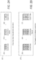
- FIG. 10 illustrates the partial computation of convolution output vectors using a two-dimensional 3x3 element convolution kernel given pre-shifted source vectors.
- the pre-shifted source vectors including Left Vector 1002, Center Vector 1004 and Right Vector 1006, may be loaded from pre-shifted data sets such as illustrated in FIG. 3 in some embodiments or may be loaded using a variety of other methods including using the Extract vector instruction 620 and method as shown in FIG. 6A and FIG. 6B .
- the various weighting coefficients of the 3x3 Kernel 1010 may be stored in some embodiments as Kernel Vectors 410 as shown in FIG. 4 or stored in other embodiments as individual data lanes of Kernel Vectors for use with the Scalar Multiply - and-Add vector instruction 860 of FIG. 8 .
- the Left, Center and Right Vectors 1002, 1004 and 1006 have respective left, center and right columns in the 3x3 Kernel 1010 where each column comprises three rows of weighting coefficients.
- Each row of the 3x3 Kernel 1010 has a respective accumulator vector, the Leading Accumulator 1018 for the first row, the Center Accumulator 1016 for the second row, and the Lagging Accumulator 1014 for the third row.
- a Multiply-and-Add vector instruction is executed three times for each of the source vectors 1002, 1004 and 1006, one time for each of the three accumulator vectors. This results in a total of nine Multiply-and-Add vector instructions, one for each of the kernel weighting coefficients.
- the row and column of the Kernel is selected based on the respective source and accumulator vectors of the operation.
- the Leading Accumulator 1018 is thus the weighted sum of the Left Vector 1002 using coefficient k1, the Center Vector 1004 using coefficient k2 and the Right Vector 1006 using coefficient k3.
- the Center Accumulator 1016 is the weighted sum of the Left Vector 1002 using coefficient k4, the Center Vector 1004 using coefficient k5 and the Right Vector 1006 using coefficient k6.
- the Lagging Accumulator 1014 is the weighted sum of the Left Vector 1002 using coefficient k7, the Center Vector 1004 using coefficient k8 and the Right Vector 1006 using coefficient k9.
- FIG. 10 illustrates only the partial computation of output vectors for a single set of source vectors. For a complete computation of each output vector, the weighted sums of vectors immediately above and below each destination vector must also be performed. By iterating the method illustrated in FIG. 10 over columns of source data, complete convolution computations may be performed while loading each source vector, along with its associated left- and right-shifted vectors, only once.
- FIG. 10 illustrates a convolution computation with a 3x3 convolution kernel for simplicity
- the computation shown is not limited to either three rows or three columns but may be used to support other numbers of rows, columns, or rows and columns.
- the computation shown is not intended to be limited to two dimensional convolution operations but may be employed to perform convolutions of greater than two dimensions.
- FIG. 11 is a flow diagram demonstrating a portion of a two dimensional, three element convolution of multiple data vectors using the Scalar Multiply-and-Add vector instruction 860 of FIG. 8 and the Extract vector instruction 620 of FIG. 6A according to some embodiments.
- the method assumes that kernel vectors vKernel and vKernel2 have already been initialized with weighting coefficients. In this example, vectors are assumed to contain eight lanes of data whereas nine weighting coefficients are required so two kernel vectors are used, though those skilled in the art will recognize that more or fewer kernel vectors may be used depending on vector and convolution kernel configurations.
- the method begins with step 1110 which loads the center source vector, vCenter. Once this vector is loaded, it is immediately available for convolution computations.
- step 1102 the left aligned source vector is loaded. Once this vector is loaded, it may be combined with vCenter to produce the left-shifted vector, vLeft. Second, the vCenter vector loaded in the previous step is used to perform weighted sum computations using the Scalar Multiply-and-Add vector instruction 860 of FIG. 8 .
- the Scalar Multiply-and-Add vector instruction 860 is represented by the SCALAR MADD operation which takes four operands: the first operand is the base vector, the second operand is the source vector, the third operand is the kernel vector, and the fourth operand is the lane of the kernel vector containing the scaling coefficient.
- the SCALAR_MADD operation multiplies each lane of the second operand by the lane specified by the third and fourth operands then adds the product to the first operand and returns a result vector.
- the vTop and vMid accumulator vectors may have partial results from previous iterations of the method and are, therefore, not initialized.
- the vBtm accumulator must be initialized.
- the base vector specified in the vBtm computation of step 1102, vZero corresponds to a vector containing 0 values in all data lanes and is common to many SIMD architectures. Using vZero in this manner provides an efficient means of initializing the vector accumulator vBtm although in some alternate embodiments, with SIMD architectures that do not offer an equivalent vZero vector, the vector accumulator may first be initialized by an alternative means.
- Step 1102 uses the SCALAR_MADD operation to compute three partial sums using the vCenter source vector and three weighting values corresponding to the center column of the 3x3 convolution kernel.
- Step 1104 loads the vSrcRight source vector.
- Step 1104 also loads the vLeft vector using the vSrcLeft and vCenter vectors already loaded as well as the Extract vector instruction 620 of FIG. 6A .
- the Extract vector instruction 620 is represented by the EXTRACT operation which takes four operands: the first and second operands are the source vectors, the third operand is the shift value, and the fourth operand is the output width.
- step 1106 loads the vRight vector using the vCenter and vSrcRight vectors already loaded as well as the Extract vector instruction 620 of FIG. 6A . Additionally, the vLeft vector loaded in step 1104 is used to perform weighted sum computations using the Scalar Multiply-and-Add vector instruction 860 of FIG. 8 using three weighting values corresponding to the left column of the 3x3 convolution kernel.
- step 1108 the vRight vector loaded in step 1106 is used to perform weighted sum computations using the Scalar Multiply-and-Add vector instruction 860 of FIG. 8 using three weighting values corresponding to the right column of the 3x3 convolution kernel.
- step 1110 the partial sums for source vectors have been completed for the source row.
- the accumulator vTop will have all rows completed and may be written to the destination vector.
- step 1112 the remaining two accumulators, vMid and vBtm, are shifted into the vTop and vMid positions, respectively in preparation for the next computation row.
- FIG. 11 illustrates a convolution computation with a 3x3 convolution kernel for simplicity
- the computation shown is not limited to either three rows or three columns but may be used to support other numbers of rows, columns, or rows and columns.
- the computation shown is not intended to be limited to two dimensional convolution operations but may be employed to perform convolutions of greater than two dimensions.
- DNNs Deep Neural Networks
- D-CNNs Convolution Networks
- GANs Generative Adversarial
- convolutions may be performed that are as efficient or more efficient that possible using specialized spatial convolutional neural network hardware while fitting into a conventional processor pipeline and thus minimizing or eliminating extra hardware.
- convolutions in these applications are often employed repeatedly for a given data set using many, small convolution kernels, this approach enables excellent processor utilization as individual convolution operations can be dedicated to individual processor cores, allowing systems to scale well merely by adding additional processor resources.
- SIMD instructions described herein may provide benefits to a large range of operations beyond convolution.
- a stride may be employed to reduce the computational demands and output size of a convolution operation.
- the stride value specifies how many data elements may be skipped for every data element computed. For example, when a stride of two is employed, every other data element is skipped and only half of the data elements are computed.
- strides may be efficiently employed by skipping rows of data elements, but for one-dimensional convolutions in the various embodiments described herein, stride factors would serve to lower the utilization of the arithmetic logic units of the execution core. For this reason, shuffled data sets may be employed to enable use of the otherwise unutilized data lanes of the vector instructions.
- the various embodiments of a Shuffle vector instruction are disclosed that enable shuffled source data vectors to be loaded for implementation of convolutions with stride values greater than one.
- FIG. 12A illustrates an example of such a Shuffle vector instruction 1240 according to some embodiments.
- source vectors 1200 are concatenated and subset of the resulting vector is extracted, starting with Source Lane 1210 and implementing a stride value specified by Stride 1220. The result is written to the Output Vector 1230. The number of source vectors 1200 required will be equal to the Stride 1220, resulting in an Output Vector comprising data elements in all data lanes.
- each of the source vectors 1200 may be specified using instruction operands.
- the source vectors 1200 may be specified using a operands specifying a range of vectors.
- FIG. 12B illustrates another example of a Shuffle vector instruction 1290 according to some embodiments.
- a fixed number of source vectors 1250 comprising one or more vectors, are concatenated and subset of the resulting vector is extracted, starting with Source Lane 1260 and implementing a stride value specified by Stride 1265.
- the result is written to the Output Vector 1280.
- the Output Vector may comprise only a contiguous subset of all data lanes. For this reason, an additional operand may be provided to specify the first Output Lane 1270 to extract the output data lanes.
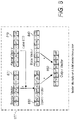
- FIG. 13 illustrates the loading of source vectors for a one dimensional, three element convolution including a stride value of two.
- Three aligned source vectors are loaded, a center source vector 1300B, a source vector immediately to the left of the center vector 1300A, and a source vector immediately to the right of the center vector 1300C.
- An extract operation 1310A is performed using the left and center source vectors, 1300A and 1300B, and the Extract vector instruction 620 of FIG. 6A using a shift value of equal to the number of data lanes in the vector, eight in the example, minus one.
- an Extract operation 1310B is performed using the center and right source vectors, 1300B and 1300C, and the Extract vector instruction 620 of FIG.
- the Shuffle operation 1330A employs the Shuffle vector instruction 1240 of FIG. 12A with a Source Lane 1210 value of zero and a Stride 1220 value of two to produce the Left Vector 1340A comprising alternating data lanes of the original Source Vectors 1300 starting with data lane l8 of Source Vector 1300A.
- the source vectors 1300B and 1300C are then input to Shuffle operations 1330B and 1330C.
- Shuffle operation 1330B employs the Shuffle vector instruction 1240 of FIG. 12A with a Source Lane 1210 value of zero and a Stride 1220 value of two to produce the Center Vector 1340B
- Shuffle operation 1330C employs the Shuffle vector instruction 1240 of FIG. 12A with a Source Lane 1210 value of one and a Stride 1220 value of two to produce the Right Vector 1340B.
- Center Vector 1340B thus comprises alternating data lanes of the original Source Vectors 1300 starting with data lane c1 of Source Vector 1300B while Right Vector 1340C comprises alternating data lanes of the original Source Vectors 1300 starting with data lane c2 of Source Vector 1300B.
- the set of vectors 1340 may then be used in a convolution such as illustrated in FIG. 5 or combined with the method shown in FIG. 11 to implement a multi-dimensional convolution with stride.
- the method illustrated in FIG. 13 is not intended to be limited to a three element convolution operation nor a stride value of two but may be used to generate vectors required to perform convolutions for a variety of kernel widths and stride values, often without the need to load additional source vectors 1300 beyond those illustrated in FIG. 13 .
- embodiments implementing kernel widths greater than three and/or strides greater than two may require additional source vectors 1300 beyond those shown in FIG. 13 as well as additional extract operations 1310 are required by those particular embodiments.
- Use of the Extract vector instruction 620 and Shuffle vector instruction 1240 or 1290 eliminates the need for pre-shifted data such as illustrated in FIG. 3 , thus eliminating growth in data size for the convolution operation implementing the stride feature.
Description
- This disclosure relates generally to digital signal processing, machine learning and neural networks, and more particularly to systems and methods for filtering of signals using convolution operations.
- In digital signal processing, a convolution is a weighted sum of an input value and its immediate neighboring values in a data set producing an output value of an output data set. These data sets may be single dimensional or multi-dimensional with corresponding data organization determining the values which are immediate neighbors of the input value. The weighting values of the convolution are specified in a convolution kernel where the kernel possesses the same number of dimensions as the input and output data sets. Convolution operations are useful in great variety of signal processing applications and are integral to the operation of many aspects of deep neural networks.
- Convolutions may be used pervasively in machine learning applications. In this context it is common to apply convolutions on a single data set using many, small convolution kernels. As a result, convolutions are often a computationally intensive portion of machine learning applications so an efficient means of performing convolution operations is of increasingly great value.
- One popular approach to improving convolution efficiency, convolution lowering, involves converting the convolution operation into an equivalent computational process that can be solved by optimized dense linear algebra. This allows the use of optimized General Matrix Multiply (GEMM) routines which are adept at leveraging inherent reuse of data, minimizing off-chip bandwidth needs, and subdividing computation that can be spread across many cores. There are also significant disadvantages to this approach, convolution lowering adds additional processor overhead and increases data size significantly. Increased data size makes caching difficult and increases off-chip bandwidth usage, leading to solutions that prefer expensive, high performance memory in lieu of caching and conventional memory technologies.
- A second approach is to perform the convolution in frequency domain. This requires the input data set and the convolution kernel to each be converted into frequency domain, the two converted data sets multiplied together, and an inverse frequency transform applied to the product. This approach offers similar advantages and disadvantages to convolution lowering, the multiplication operation may again be implemented by GEMM routines but additional computational overhead is added and memory footprint may increase dramatically for small kernel sizes. In machine learning applications where many, small kernels are used, convolution in frequency domain is unappealing due to the requirement to convert the many, small kernels to frequency domain.
- A third approach, commonly referred to as "direct convolution", applies convolution filters directly to data in time or spatial domain. This approach avoids the additional computational overhead and memory growth of the previous approaches but suffers from much lower processor utilization, less parallelism and exploitation of reuse, or hardware that is dedicated only to solving convolutions. Typically, such hardware does not leverage existing resources of conventional hardware and is nontrivial to program and optimize for a given deep neural network.
-
US 2017/024218 A1 relates to a sliding window operation in which a SIMD lane is configured to perform a sliding window operation on first input data elements in a lane of a first register and second input data elements in a lane of a second register.EP 3 093 757 A2 relates to a multi-dimensional sliding window operation for a vector processor.US 2015/086134 A1 relates to a low power programmable image processor including a load and store unit, a shift register unit, and a mapping unit to perform convolution operations, wherein the shift register unit is configured to load and store at least a portion of the image; the mapping unit is configured to generate a number of shifted versions of image pixel data and corresponding stencil data from the portion of the image pixel data, and concurrently perform one or more operations on each image pixel value in the shifted versions of the portion of the image pixel data and a corresponding stencil value in the corresponding stencil data. - Methods and systems for providing efficient direct convolution operations using a central processing unit (CPU) providing vector instructions are described. Efficient direct convolution operations are useful in machine learning and deep neural network applications where convolution operations may demand significant memory bandwidth and computational resources. These convolution applications are commonly characterized by the use of smaller convolution kernel sizes where direct convolution approaches would otherwise be memory bandwidth constrained. By implementing direct convolutions on the main CPU using the approaches disclosed herein, a system may avoid the need for dedicated hardware accelerators or general purpose GPU (GPGPU) solutions, thus allowing better performance scaling in these applications, while fully utilizing computational resources as well as cache and memory bandwidth in the smaller kernel sizes typically used in machine learning applications..
- To increase data-level parallelism in hardware, a processor may include vector instructions providing parallel execution lanes for each instruction executed, such as in a Single Instruction Multiple Data (SIMD) micro-architecture. This type of micro-architecture may provide higher throughput for certain applications than single-lane or general-purpose micro-architectures. While general-purpose micro-architectures operate on a single lane of data contained in registers, SIMD micro-architectures operate on data contained in vectors composed of multiple lanes of independent data.
- Multiple SIMD source vectors are loaded, one source vector aligned with the destination vector to be computed, one or more source vectors including left-partial data with respect to the destination vector, and one or more source vectors including right-partial data with respect to the destination vector. Each of these source vectors is multiplied with respective convolution coefficient vectors and added to accumulator vector. Once all source vectors have been processed, the accumulator vector is written to the destination vector.
- In some embodiments, the convolution to be performed may be a multi-dimensional convolution. In these embodiments multiple accumulator vectors may be computed simultaneously using the same loaded source vectors. The various source vectors may be multiplied with other convolution coefficient vectors corresponding to other dimensions of the convolution kernel and the multiple accumulator vectors may not be written until all source vectors for a given destination vector have been processed.
- In some embodiments, a SIMD instruction may be provided to extract unaligned SIMD vectors from pairs of aligned SIMD vectors. In these embodiments, the aligned source vector as well as the plurality of shifted source vectors may be loaded from a common data source.
- In some embodiments, a SIMD instruction may be provided to perform a SIMD Scalar Multiply-and-Add operation where each lane of a data vector is multiplied by a scalar quantity and added to a respective lane of a base vector.
- In some embodiments, convolution operations may be performed on multiple input data sets simultaneously by computing partial-resolution output data sets using pre-interleaved source data. In these embodiments, a SIMD instruction may be provided to perform a de-interlacing operation on computed data vectors to extract partial-resolution output data vectors.
- The various embodiments disclosed transform the computation of direct convolutions from operations traditionally limited by memory bandwidth to ones that fully exploit the computational resources and bandwidth of cache and memory subsystems while requiring only the main CPU, and while these embodiments are especially suited to direct convolution computations, it should be noted that they may apply more generally to a variety of computational tasks, for example to general parallel traversal techniques.
-
-
FIG. 1 is a block diagram of one embodiment of a computer system. -
FIG. 2A is a block diagram illustrating a one-dimensional convolution of a data element with a three element convolution kernel. -
FIG. 2B is a block diagram illustrating a two-dimensional convolution of a data element with a 3x3 element convolution kernel. -
FIG. 3 is a block diagram illustrating left- and right-shifted data streams supporting aligned loading of source vectors for use with a three element convolution kernel, according to at least some embodiments. -
FIG. 4 illustrates the computing of an output vector for a three element, one-dimensional convolution using aligned, left-shifted and right-shifted source vectors with respective kernel vectors, according to at least some embodiments. -
FIG. 5 is a flow diagram illustrating one embodiment of a method for computing a series of output vectors of a data set comprising a three element, one-dimensional convolution of an input data set. -
FIG. 6A illustrates an Extract vector instruction that generates a data vector comprising a subset of the concatenation of two source vectors, according to at least some embodiments. -
FIG. 6B illustrates the use of the Extract vector instruction ofFIG. 6A to load a set of source vectors for a convolution operation using a set of aligned, sequential source input vectors, according to at least some embodiments. -
FIG. 7 is a flow diagram illustrating one embodiment of a method for computing a series of output vectors of a data set comprising a three element, one-dimensional convolution of an input data set and using the Extract vector instruction ofFIG. 6A . -
FIG. 8 illustrates a Scalar Multiply-and-Add vector instruction that derives a scalar value, scales each of the data lanes of a vector by the scalar value to produce a scaled vector, and adds the scaled vector to a base vector to generate an output vector. -
FIG. 9 is a flow diagram illustrating one embodiment of a method for computing a series of output vectors of a data set comprising a three element, one-dimensional convolution of an input data set and using the Scalar Multiply-and-Add vector instruction ofFIG. 8 . -
FIG. 10 illustrates the partial computing of a plurality of output vectors for a 3x3 element, two-dimensional convolution using aligned, left-shifted and right-shifted source vectors with respective kernel vectors, according to at least some embodiments. -
FIG. 11 is a flow diagram illustrating one embodiment of a method for computing a column of output vectors of a data set comprising a 3x3 element, two-dimensional convolution of an input data set and using the Scalar Multiply-and-Add vector instruction ofFIG. 8 and the Extract vector instruction ofFIG. 6A . -
FIG. 12A illustrates one embodiment of a Shuffle vector instruction that generates a data vector comprising Shuffled data lanes of the concatenation of multiple interlaced source vectors including a stride factor and starting source lane. -
FIG. 12B illustrates one embodiment of a Shuffle vector instruction that generates a data vector comprising del-interlaced data lanes from an interlaced source vector including a stride factor, starting source lane, and starting output lane. -
FIG. 13 illustrates the use of the Extract vector instruction ofFIG. 6A and the Shuffle vector instruction ofFIG. 12A to load a set of source vectors for a convolution operation including a stride value of two and using a set of aligned, sequential source input vectors, according to at least some embodiments. - While the disclosure is described herein by way of example for several embodiments and illustrative drawings, those skilled in the art will recognize that the disclosure is not limited to embodiments or drawings described. It should be understood that the drawings and detailed description hereto are not intended to limit the disclosure to the particular form disclosed, but on the contrary, the disclosure is to cover all modifications, equivalents and alternatives falling within the scope as defined by the appended claims. Any headings used herein are for organizational purposes only and are not meant to limit the scope of the description or the claims. As used herein, the word "may" is used in a permissive sense (i.e., meaning having the potential to) rather than the mandatory sense (i.e. meaning must). Similarly, the words "include", "including", and "includes" mean including, but not limited to.
- Various units, circuits, or other components may be described as "configured to" perform a task or tasks. In such contexts, "configured to" is a broad recitation of structure generally meaning "having circuitry that" performs the task or tasks during operation. As such, the unit/circuit/component can be configured to perform the task even when the unit/circuit/component is not currently on. In general, the circuitry that forms the structure corresponding to "configured to" may include hardware circuits. Similarly, various units/circuits/components may be described as performing a task or tasks, for convenience in the description. Such descriptions should be interpreted as including the phrase "configured to."
- This specification includes references to "one embodiment" or "an embodiment." The appearances of the phrases "in one embodiment" or "in an embodiment" do not necessarily refer to the same embodiment, although embodiments that include any combination of the features are generally contemplated, unless expressly disclaimed herein. Particular features, structures, or characteristics may be combined in any suitable manner consistent with this disclosure.
- Deep neural networks have become increasingly important in solving a wide range of generic problems in conjunction with large data sets. These networks, however, spend a significant amount of processing time in convolutions and matrix multiplications, with processing time more than doubled per pass during the training phase in order to update neuron weights. A large number of passes may further be needed for slowly converging networks. As a result, efficient convolution computations are increasingly important.
- Methods and systems for providing efficient direct convolution operations using a central processing unit (CPU) providing vector instructions are described. Efficient direct convolution operations are useful in deep neural network applications and other applications where convolution operations may demand significant computational resources. By implementing convolutions on the main CPU, a system may avoid the need for dedicated hardware accelerators or general purpose GPU (GPGPU) solutions, thus allowing better performance scaling in convolutional neural network applications.
-
FIG. 1 provides a block diagram of one embodiment of a computer system.Computer System 100 includes aProcessor 110, aMemory 120, and aMass Storage Device 140 attached to an IO Bus 130. TheProcessor 110 includes anExecution Core 112, including aRegister File 114, coupled to aCache 116. It is noted that, although specific components are shown and described inComputer System 100, in alternative embodiments, different components and numbers of components may be present. For example,Computer System 100 may not include theMass Storage Device 140 while multiple processors similar to theProcessor 110 may be included. Additionally, while asingle Cache 116 is shown internal to theProcessor 110, a hierarchical cache including multiple levels both internal and external to theProcessor 110 may be present.Computer System 100 may also include graphics processors, user-interface devices, network cards, and/or other peripheral devices that are coupled toProcessor 110 using the IO Bus 130, a network, or other communication channel. - In various embodiments, the
Processor 110 may be representative of a general-purpose processor that performs computational operations. For example, theProcessor 110 may be a central processing unit (CPU) such as a microprocessor, microcontroller, application-specific integrated circuit (ASIC), or field-programmable gate array (FPGA). TheProcessor 110 may be a standalone component or may be integrated with other components (e.g. other processors, or other components in a system on a chip (SOC) or FPGA) or may be a component in a multichip module (MCM) with other components. TheProcessor 110 may include one or more mechanisms for vector processing (e.g., vector execution units). - As illustrated in
FIG. 1 , theProcessor 110 may include anExecution Core 112. TheExecution Core 112 may be configured to execute instructions defined in an instruction set architecture implemented by theProcessor 110. TheExecution Core 112 may have various micro-architectural features and implementation features, as desired. For example, theExecution Core 112 may include superscalar or scalar implementations. TheExecution Core 112 may include in-order or out-of-order implementations, and speculative or non-speculative implementations. TheExecution Core 112 may include any combination of the above features. The implementations may include microcode in some embodiments. TheExecution Core 112 may also include a variety of execution units, each execution unit configured to execute operations of various types (e.g. integer, floating point, vector, multimedia, load/store, etc.). TheExecution Core 112 may include different numbers pipeline stages and various other performance-enhancing features such as branch prediction. TheExecution Core 112 may include one or more of instruction decode units, schedulers or reservations stations, reorder buffers, memory management units, I/O interfaces, etc. - The
Register File 114 may include a set of registers that may be used to store operands for various instructions. TheRegister File 114 may include registers of various data types, based on the type of operand theExecution Core 112 is configured to store in the registers (e.g. integer, floating point, multimedia, vector, etc.). TheRegister File 114 may include architected registers (i.e. those registers that are specified in the instruction set architecture implemented by the Processor 110). Alternatively or in addition, theRegister File 114 may include physical registers (e.g. if register renaming is implemented in the Execution Core 112). - The
Cache 116 may be illustrative of any caching structure. For example, theCache 116 may be implemented as a Harvard architecture (separate instruction cache for instruction fetching and data cache for data read/write by execution units for memory-referencing operations), as a shared instruction and data cache, etc. In some embodiments, load/store execution units may be provided to execute the memory-referencing operations. - An instruction may be an executable entity defined in an instruction set architecture implemented by the
Processor 110. There are a variety of instruction set architectures (e.g. the x86 architecture original developed by Intel, ARM from ARM Holdings, Power and PowerPC from IBM/Motorola, etc.). Each instruction is defined in the instruction set architecture, including its coding in memory, its operation, and its effect on registers, memory locations, and/or other processor state. A given implementation of the instruction set architecture may execute each instruction directly, although its form may be altered through decoding and other manipulation in the processor hardware. Another implementation may decode at least some instructions into multiple instruction operations for execution by the execution units in theProcessor 110. Some instructions may be microcoded in some embodiments. - The mass-
storage device 110,Memory 120 andCache 116 are storage devices that collectively form a memory hierarchy that stores data and instructions forProcessor 110. More particularly, the mass-storage device 110 may be a high-capacity, non-volatile memory, such as a disk drive or a large flash memory unit with a long access time, whileCache 116 andMemory 120 may be smaller but with shorter access times. These faster semiconductor memories store copies of frequently used data.Memory 120 may be representative of a memory device in the dynamic random access memory (DRAM) family of memory devices. The size ofMemory 120 is typically larger thanCache 116 whereasCache 116 is typically implemented using smaller devices in the static random access memories (SRAM) family of devices. In some embodiments,cache 116,Memory 120 and mass-storage device 110 are shared between one or more processors inComputer System 100. - It is noted the data and instructions may be stored on a non-transitory computer-readable storage device, which may be any device or storage medium that can store code and/or data for use by a computer system (e.g., Computer System 100). Generally speaking, a non-transitory computer-readable storage device includes, but is not limited to, volatile memory, non-volatile memory, magnetic and optical storage devices such as disk drives, magnetic tape, compact discs (CDs), digital versatile discs or digital video discs (DVDs), or other media capable of storing computer-readable media now known or later developed. As such, mass-
storage device 110,Memory 120 andCache 116 are all examples of non-transitory computer readable storage media. - As mentioned above, the
Execution Core 112 may be configured to execute vector instructions. The vector instructions may be defined as single instruction-multiple-data (SIMD) instructions in the classical sense, in that they may define the same operation to be performed on multiple data elements in parallel. The data elements operated upon by an instance of an instruction may be referred to as a vector and are organized in data lanes. These data elements may contain data of various, multi-bit data types based on the type of operand theExecution Core 112 is configured to store in the registers (e.g. integer, floating point, multimedia, vector, etc.). For simplicity, vectors in the disclosure are represented as including eight data lanes, although it should be understood that this is not intended to limit the disclosure to this particular vector organization. On the contrary, those skilled in the art will recognize that vectors may be configured provide any number of data lanes. In some embodiments, there may be 32 vector registers in the vector register file, and each vector register may include 128 bits. However, in alternative embodiments, there may be different numbers of vector registers and/or different numbers of bits per register. Generally, vector lengths may be implemented as powers of two (e.g., two, four, eight, etc.). However, in some embodiments, vector lengths need not be powers of two. Furthermore, embodiments which implement register renaming may include any number of physical registers that may be allocated to architected vector registers. Architected registers may be registers that are specifiable as operands in vector instructions. - In digital signal processing, a convolution is a weighted sum of an input value and its immediate neighboring values in a data set producing an output value of an output data set. These data sets may be one-dimensional or multi-dimensional with corresponding data organization determining the values which are immediate neighbors of the input value. The weighting values of the convolution are specified in a convolution kernel where the kernel possesses the same number of dimensions as the input and output data sets.
-
FIG. 2A depicts a one-dimensional convolution operation 225. InFIG. 2A , the data element s2 ofSource Data 200 is to be convolved with a three-element Convolution Kernel 210 to produce data element o2 in theOutput Data 220. In addition, data elements s1 and s3 ofSource Data 200 are required for the convolution as immediate left and right neighbors of the data element s2. The output data is the weighted sum of the Source Data elements with respective weighting factors k1-k3 of theConvolution Kernel 210, in other words o2 = k1∗s1 + k2∗s2 + k3∗s3. -
FIG. 2B depicts a twodimensional convolution operation 275. InFIG. 2B , the data element s5 ofSource Data 250 is to be convolved with a 3x3-element Convolution Kernel 260 to produce data element o5 in theOutput Data 270. In addition, data elements s1-s4 and s6-s9 ofSource Data 250 are required for the convolution as immediate neighbors, left, right, above and below, of the data element s2. The output data is the weighted sum of the Source Data elements with respective weighting factors k1-k9 of theConvolution Kernel 260, in other words o5 = k1∗s1 + k2∗s2 + k3∗s3 + k4∗s4 + k5∗s5 + k6∗s6 + k7∗s7 + k8∗s8 + k9∗s9. - It should be understood that the examples of one and two dimensional convolutions are not intended to limit the disclosure to these particular convolution organizations. On the contrary, those skilled in the art will recognize that convolutions may be performed with any number of dimensions. Furthermore, the examples are not intended to limit convolutions to three elements per dimension and those skilled in the art will recognize that convolutions may be performed with other numbers of elements per dimension.
-
FIG. 3 illustrates a method of pre-shifting of source data sets according to some embodiments. In addition to anAligned Data 300,FIG. 3 shows Left ShiftedData 310 corresponding to a data set where vector alignment has been shifted left one data lane and Right ShiftedData 320 corresponding to a data set where vector alignment has been shifted right one data lane. The three data sets, 300, 310 and 320, correspond to a convolution operation using a convolution kernel consisting of three columns. Such convolutions may be one-dimensional convolutions or multi-dimensional convolutions. Furthermore, it should be understood that the pre-shifting of data sets in not limited to convolutions of three columns. Those skilled in the art will recognize that any number of columns may be supported, for example a five column convolution may have a total of five source data sets, the three shown inFIG.3 , 300, 310 and 320, as well as a double left-shifted data set and a double right-shifted data set. -
FIG. 4 illustrates the computation of a convolution output vector using a one-dimensional three element convolution kernel given pre-shifted source vectors. The pre-shifted source vectors may be loaded from pre-shifted data sets such as illustrated inFIG. 3 in some embodiments but may also be loaded using a variety of other methods in other embodiments. TheKernel Vectors Convolution Kernel 210 ofFIG. 2A . Each Kernel Vector is comprised of a respective Convolution Kernel weighting value replicated into all data lanes of the Kernel Vector. For example, theKernel Vector 410B corresponds to the middle weighting value of theConvolution Kernel 210 and thus has the weighting value k2 replicated into all its data lanes. TheOutput Vector 420 is thus the sum of the source vectors 400 multiplied by their respective kernel vectors 410. The convolution computation illustrated inFIG. 4 is not limited performing convolutions involving only three kernel columns but may be expanded to implement any number of kernel columns. -
FIG. 5 is a flow diagram demonstrating a one dimensional, three element convolution of multiple data vectors according to some embodiments. The method begins withstep 502 which initializes three kernel vectors, vKLeft, vKCenter and vKRight corresponding to Kernel Vectors 410 ofFIG. 4 . As these vectors remain constant for the duration of the convolution operation, they may be loaded only once. - The method proceeds to step 504 which loads the aligned and shifted source vectors vLeft, vCenter, and vRight corresponding to the Vectors 400 in
FIG. 4 . In some embodiments, vLeft, vCenter, and vRight may be loaded from pre-shifted data sets such as those shown inFIG. 3 while in other embodiments they may be loaded through other means. - The method then proceeds to
steps 506 which performs the three weighted sums added to vector accumulator vAcc. Each weighted value is computed using a Multiply-and-Add vector instruction common to many SIMD architectures although in some embodiments it may be implemented using a combination of arithmetic vector instructions. Instep 506 the Multiply-and-Add vector instruction is represented by the MADD operation which takes three operands: the first operand is the base vector, the second operand is the source vector, and the third operand is the kernel vector. The MADD operation multiplies the second and third operands then adds the product to the first operand and returns a result vector. In the first MADD operation the base vector specified, vZero, corresponds to a vector containing 0 values in all data lanes and is common to many SIMD architectures. Using vZero in this manner provides an efficient means of initializing the vector accumulator vAcc although in some alternate embodiments, with SIMD architectures that do not offer an equivalent vZero vector, the vector accumulator vAcc may first be initialized by an alternative means. In the remaining two MADD operations, the base vector specified is the accumulator vAcc. The three source vectors, vLeft, vCenter and vRight, are multiplied by their respective kernel vectors, vKLeft, vKCenter, and vKRight, and added to the accumulator vAcc. - Once the MADD operations are completed, the method proceeds to step 508 where the accumulator vector is written to the destination address. The number of remaining vectors is checked in
step 510 and the process continues atstep 504 until all vectors have been generated. - While the embodiment disclosed in
FIG. 5 performs a one-dimensional convolution with a three element kernel, it should be understood that the embodiment is not intended to be limited to three elements but may include a variety of kernel widths. While the embodiment onFIG. 5 implements an efficient computation of weighted sums, it relies on pre-shifted source data, such as those shown inFIG. 3 , and for wider kernel widths, the use of these pre-shifted data sets results in larger demands on memory and off-chip bandwidth. For this reason, a vector instruction to derive the shifted source data is disclosed inFIG. 6A . The use of this vector instruction, when combined with the embodiment ofFIG. 5 , minimizes off-chip bandwidth requirements, particularly with wider kernel widths. - In some embodiments, an Extract vector instruction may be used to generate the shifted data vectors required for the convolution computations using a pair of aligned source vectors. The use of the Extract vector instruction allows the of source data as originally supplied for a convolution operation, thus enabling efficient use of memory and cache bandwidth.
FIG. 6A illustrates an example of such anExtract vector instruction 620. InFIG. 6A , two consecutive source vectors, 600A and 600B, are concatenated and subset of the resulting double-width vector is extracted starting at an offset data lane specified byShift 605 to produce theOutput Vector 610. Optionally, andOutput Width 615 may be specified which allows for the Output Vector to contain less than the full vector width of output data lanes. In this case, the rightmost lanes of theOutput Vector 610 will contain zero. InFIG. 6A , a vector width of eight data lanes is shown with aShift 605 value of four and anOutput Width 615 value of six. - Using the Extract vector instruction, various embodiments of convolution operations may load shifted source vectors for a wide variety of kernel widths using only three aligned source vectors, the center aligned vector and an aligned vector to the immediate left and immediate right of the center aligned vector.
-
FIG. 6B illustrates the loading of source vectors for a one dimensional, three element convolution such as shown inFIG. 4 . Three aligned source vectors are loaded, acenter source vector 625B, a source vector immediately to the left of thecenter vector 625A, and a source vector immediately to the right of the center vector 625C. An Extract Leftoperation 630 is performed using the left and center source vectors, 625A and 625B, and theExtract vector instruction 620 ofFIG. 6A using a shift value of equal to the number of data lanes in the vector, eight in the example, minus one. This operation results in theLeft Vector 650. Likewise, anExtract Right operation 640 is performed using the center and right source vectors, 625B and 625C, and theExtract vector instruction 620 ofFIG. 6A using a shift value of one. This operation results in theRight Vector 670. The set ofvectors FIG. 5 . Those skilled in the art will recognize that the method illustrated inFIG. 6B is not intended to be limited to a three element convolution operation but may be used to generate vectors required to perform convolutions for a variety of kernel widths, often without the need to load additional source vectors 625 beyond those illustrated inFIG. 6B . Furthermore, use of theExtract vector instruction 620 eliminates the need for pre-shifted data such as illustrated inFIG. 3 , this eliminating growth in data size for the convolution operation. -
FIG. 7 is a flow diagram demonstrating a one dimensional, three element convolution of multiple data vectors using the Extract method ofFIG. 6B according to some embodiments. The convolution ofFIG.7 minimizes the number of loads and stores of vector data to main memory and uses the original source data without and precomputing of vector data. Furthermore, the sequence of loads and stores to main memory enables high performance of system caches, resulting in a high performance convolution implementation that balances computational demands with cache and memory bandwidth. - The method begins with
step 702 which initializes three kernel vectors, vKLeft, vKCenter and vKRight corresponding to Kernel Vectors 410 ofFIG. 4 . As these vectors remain constant for the duration of the convolution operation, they may be loaded only once. Additionally, the left-aligned source vector, vSrcLeft, is initialized and the first source vector is loaded into vCenter. - The method proceeds to step 704 which loads the right-aligned source vector vSrcRight. As vSrcLeft and vCenter are already loaded, once vSrcRight, is loaded the method proceeds to
steps 706 where theExtract vector instruction 620 is used to produce the left- and right-shifted vectors, vLeft and vRight, for the convolution computation. Instep 706 theExtract vector instruction 620 is represented by the EXTRACT operation which takes four operands: the first and second operands are the source vectors, the third operand is the shift value, and the fourth operand is the output width.Steps 706 produces the left- and right-shifted source vectors vLeft and vRight that, when combined with the center vector vCenter, form the vectors used to perform the convolution. - The method then proceeds to
steps 708 which performs the three weighted sums added to vector accumulator vAcc. Each weighted value is computed using a Multiply-and-Add vector instruction common to many SIMD architectures although in some embodiments it may be implemented using a combination of arithmetic vector instructions. Instep 708 the Multiply-and-Add vector instruction is represented by the MADD operation which takes three operands: the first operand is the base vector, the second operand is the source vector, and the third operand is the kernel vector. The MADD operation multiplies the second and third operands then adds the product to the first operand and returns a result vector. In the first MADD operation the base vector specified, vZero, corresponds to a vector containing 0 values in all data lanes and is common to many SIMD architectures. Using vZero in this manner provides an efficient means of initializing the vector accumulator vAcc although in some alternate embodiments, with SIMD architectures that do not offer an equivalent vZero vector, the vector accumulator vAcc may first be initialized by an alternative means. In the remaining two MADD operations, the base vector specified is the accumulator vAcc. The three source vectors, vLeft, vCenter and vRight, are multiplied by their respective kernel vectors, vKLeft, vKCenter, and vKRight, and added to the accumulator vAcc. - Once the MADD operations are completed, the method proceeds to step 710 where the accumulator vector is written to the destination address. In
step 712, the vCenter and vSrcRight vectors are shifted to become the vSrcLeft and vCenter vectors, respectively, then the number of remaining vectors is checked instep 714 and the process continues atstep 704 until all vectors have been generated. - In some embodiments, a Scalar Multiply-and-Add vector instruction may be used. In a traditional Multiply-and-Add vector instruction, two vectors are multiplied and the product added to a third vector to produce an output vector. In the disclosed Scalar Multiply-and-
Add vector instruction 860 shown inFIG. 8 , each lane of aSource Vector 800 is multiplied by a scalar quantity specified byLane 820 of aKernel Vector 810 to form aScaled Vector 830 which is added to aBase Vector 840 to produce anOutput Vector 850. Using this vector instruction allows the weighting coefficients of the convolution kernel to be stored compactly in individual lanes of vectors rather than using a vector for each weighting coefficient. This reduces usage of theregister file 114 as well as off-chip bandwidth requirements. -
FIG. 9 is a flow diagram demonstrating a one dimensional, three element convolution of multiple data vectors using the Scalar Multiply-and-Add vector instruction 860 ofFIG. 8 according to some embodiments. The method begins withstep 902 which initializes a single kernel vector, vKernel, with weighting coefficients in various lanes of the vector. As this vector remains constant for the duration of the convolution operation, it may be loaded only once. - The method proceeds to step 904 which loads the aligned and shifted source vectors vLeft, vCenter, and vRight corresponding to the Vectors 400 in
FIG. 4 . In some embodiments, vLeft, vCenter, and vRight may be loaded from pre-shifted data sets such as those shown inFIG. 3 while in other embodiments they may be loaded through other means such as using theExtract vector instruction 620 and method as shown inFIG. 6A and FIG. 6B . - The method then proceeds to
steps 906 which performs the three weighted sums for vector accumulator vAcc. Each weighted value is computed using the Scalar Multiply-and-Add vector instruction 860 ofFIG. 8 . Instep 906 the Scalar Multiply-and-Add vector instruction 860 is represented by the SCALAR_MADD operation which takes four operands: the first operand is the base vector, the second operand is the source vector, the third operand is the kernel vector, and the fourth operand is the lane of the kernel vector containing the scaling coefficient. The SCALAR MADD operation multiplies each lane of the second operand by the lane specified by the third and fourth operands then adds the product to the first operand and returns a result vector. In the first SCALAR_MADD operation, the base vector specified, vZero, corresponds to a vector containing 0 values in all data lanes and is common to many SIMD architectures. Using vZero in this manner provides an efficient means of initializing the vector accumulator vAcc although in some alternate embodiments, with SIMD architectures that do not offer an equivalent vZero vector, the vector accumulator vAcc may first be initialized by an alternative means. In the remaining two SCALAR_MADD operations, the base vector specified is the accumulator vAcc. The three source vectors, vLeft, vCenter and vRight, are multiplied by their respective kernel scalar values loaded from respective data lanes of the kernel vector, vKernel, and added to the accumulator vAcc. - Once the SCALAR_MADD operations are completed, the method proceeds to step 908 where the accumulator vector is written to the destination address. The number of remaining vectors is checked in
step 910 and the process continues atstep 904 until all vectors have been generated. - While the embodiment disclosed in
FIG. 9 performs a one-dimensional convolution with a three element kernel, it should be understood that the embodiment is not intended to be limited to three elements but may include a variety of kernel widths. Furthermore, while the various embodiments discussed previously have implemented one-dimensional convolution operations, it should be understood that the methods discussed may be applied to multi-dimensional convolution operations as well. In the case of a multi-dimensional convolution, a set of source vectors such as shown inFIG. 4 may be applied simultaneously to multiple accumulator vectors to implement a multi-dimensional convolution. -
FIG. 10 illustrates the partial computation of convolution output vectors using a two-dimensional 3x3 element convolution kernel given pre-shifted source vectors. The pre-shifted source vectors, including Left Vector 1002, Center Vector 1004 and Right Vector 1006, may be loaded from pre-shifted data sets such as illustrated inFIG. 3 in some embodiments or may be loaded using a variety of other methods including using theExtract vector instruction 620 and method as shown inFIG. 6A and FIG. 6B . The various weighting coefficients of the3x3 Kernel 1010 may be stored in some embodiments as Kernel Vectors 410 as shown inFIG. 4 or stored in other embodiments as individual data lanes of Kernel Vectors for use with the Scalar Multiply - and-Add vector instruction 860 ofFIG. 8 . The Left, Center and Right Vectors 1002, 1004 and 1006 have respective left, center and right columns in the3x3 Kernel 1010 where each column comprises three rows of weighting coefficients. Each row of the3x3 Kernel 1010 has a respective accumulator vector, the Leading Accumulator 1018 for the first row, theCenter Accumulator 1016 for the second row, and theLagging Accumulator 1014 for the third row. - A Multiply-and-Add vector instruction is executed three times for each of the source vectors 1002, 1004 and 1006, one time for each of the three accumulator vectors. This results in a total of nine Multiply-and-Add vector instructions, one for each of the kernel weighting coefficients. For each Multiply-and-Add vector instruction, the row and column of the Kernel is selected based on the respective source and accumulator vectors of the operation. The Leading Accumulator 1018 is thus the weighted sum of the Left Vector 1002 using coefficient k1, the Center Vector 1004 using coefficient k2 and the Right Vector 1006 using coefficient k3. Likewise, the
Center Accumulator 1016 is the weighted sum of the Left Vector 1002 using coefficient k4, the Center Vector 1004 using coefficient k5 and the Right Vector 1006 using coefficient k6. Finally, theLagging Accumulator 1014 is the weighted sum of the Left Vector 1002 using coefficient k7, the Center Vector 1004 using coefficient k8 and the Right Vector 1006 using coefficient k9. -
FIG. 10 illustrates only the partial computation of output vectors for a single set of source vectors. For a complete computation of each output vector, the weighted sums of vectors immediately above and below each destination vector must also be performed. By iterating the method illustrated inFIG. 10 over columns of source data, complete convolution computations may be performed while loading each source vector, along with its associated left- and right-shifted vectors, only once. - While
FIG. 10 illustrates a convolution computation with a 3x3 convolution kernel for simplicity, those skilled in the art will recognize that the computation shown is not limited to either three rows or three columns but may be used to support other numbers of rows, columns, or rows and columns. Furthermore, the computation shown is not intended to be limited to two dimensional convolution operations but may be employed to perform convolutions of greater than two dimensions. -
FIG. 11 is a flow diagram demonstrating a portion of a two dimensional, three element convolution of multiple data vectors using the Scalar Multiply-and-Add vector instruction 860 ofFIG. 8 and theExtract vector instruction 620 ofFIG. 6A according to some embodiments. The method assumes that kernel vectors vKernel and vKernel2 have already been initialized with weighting coefficients. In this example, vectors are assumed to contain eight lanes of data whereas nine weighting coefficients are required so two kernel vectors are used, though those skilled in the art will recognize that more or fewer kernel vectors may be used depending on vector and convolution kernel configurations. The method begins withstep 1110 which loads the center source vector, vCenter. Once this vector is loaded, it is immediately available for convolution computations. - The method then proceeds to step 1102 which performs two functions. First, the left aligned source vector is loaded. Once this vector is loaded, it may be combined with vCenter to produce the left-shifted vector, vLeft. Second, the vCenter vector loaded in the previous step is used to perform weighted sum computations using the Scalar Multiply-and-
Add vector instruction 860 ofFIG. 8 . - The Scalar Multiply-and-
Add vector instruction 860 is represented by the SCALAR MADD operation which takes four operands: the first operand is the base vector, the second operand is the source vector, the third operand is the kernel vector, and the fourth operand is the lane of the kernel vector containing the scaling coefficient. The SCALAR_MADD operation multiplies each lane of the second operand by the lane specified by the third and fourth operands then adds the product to the first operand and returns a result vector. - The vTop and vMid accumulator vectors may have partial results from previous iterations of the method and are, therefore, not initialized. The vBtm accumulator, however, must be initialized. The base vector specified in the vBtm computation of
step 1102, vZero, corresponds to a vector containing 0 values in all data lanes and is common to many SIMD architectures. Using vZero in this manner provides an efficient means of initializing the vector accumulator vBtm although in some alternate embodiments, with SIMD architectures that do not offer an equivalent vZero vector, the vector accumulator may first be initialized by an alternative means.Step 1102 uses the SCALAR_MADD operation to compute three partial sums using the vCenter source vector and three weighting values corresponding to the center column of the 3x3 convolution kernel. - The method then proceeds to step 1104 which loads the vSrcRight source vector.
Step 1104 also loads the vLeft vector using the vSrcLeft and vCenter vectors already loaded as well as theExtract vector instruction 620 ofFIG. 6A . TheExtract vector instruction 620 is represented by the EXTRACT operation which takes four operands: the first and second operands are the source vectors, the third operand is the shift value, and the fourth operand is the output width. - The method then proceeds to step 1106 which loads the vRight vector using the vCenter and vSrcRight vectors already loaded as well as the
Extract vector instruction 620 ofFIG. 6A . Additionally, the vLeft vector loaded instep 1104 is used to perform weighted sum computations using the Scalar Multiply-and-Add vector instruction 860 ofFIG. 8 using three weighting values corresponding to the left column of the 3x3 convolution kernel. - The method then proceeds to step 1108 where the vRight vector loaded in
step 1106 is used to perform weighted sum computations using the Scalar Multiply-and-Add vector instruction 860 ofFIG. 8 using three weighting values corresponding to the right column of the 3x3 convolution kernel. - The method then proceeds to step 1110 where the partial sums for source vectors have been completed for the source row. At this point, the accumulator vTop will have all rows completed and may be written to the destination vector. The method the proceeds to step 1112 where the remaining two accumulators, vMid and vBtm, are shifted into the vTop and vMid positions, respectively in preparation for the next computation row.
- While the flow diagram of
FIG. 11 illustrates a convolution computation with a 3x3 convolution kernel for simplicity, those skilled in the art will recognize that the computation shown is not limited to either three rows or three columns but may be used to support other numbers of rows, columns, or rows and columns. Furthermore, the computation shown is not intended to be limited to two dimensional convolution operations but may be employed to perform convolutions of greater than two dimensions. - While the various embodiments of convolution operations discussed herein may be applied in great variety of applications, the various embodiments may be especially useful when applied to machine learning and deep neural networks. In these applications, the convolution step is recognized as a significantly time intensive and resource inefficient operation. As a result, processors may be tailored to accelerate this operation. Convolution stages are increasingly added to a wide variety of Deep Neural Networks (DNNs), including Convolution Networks (D-CNNs), Recurrent Neural Networks such as LSTMs, Generative Adversarial (GANs), etc. By performing direct convolution operations using SIMD instructions available on general purpose CPU cores, convolutions may be performed that are as efficient or more efficient that possible using specialized spatial convolutional neural network hardware while fitting into a conventional processor pipeline and thus minimizing or eliminating extra hardware. Furthermore, as convolutions in these applications are often employed repeatedly for a given data set using many, small convolution kernels, this approach enables excellent processor utilization as individual convolution operations can be dedicated to individual processor cores, allowing systems to scale well merely by adding additional processor resources. Finally, the various embodiments of SIMD instructions described herein may provide benefits to a large range of operations beyond convolution.
- In some embodiments, a stride may be employed to reduce the computational demands and output size of a convolution operation. In this case, the stride value specifies how many data elements may be skipped for every data element computed. For example, when a stride of two is employed, every other data element is skipped and only half of the data elements are computed. For multi-dimensional convolutions dimensions, strides may be efficiently employed by skipping rows of data elements, but for one-dimensional convolutions in the various embodiments described herein, stride factors would serve to lower the utilization of the arithmetic logic units of the execution core. For this reason, shuffled data sets may be employed to enable use of the otherwise unutilized data lanes of the vector instructions. In this case, the various embodiments of a Shuffle vector instruction are disclosed that enable shuffled source data vectors to be loaded for implementation of convolutions with stride values greater than one.
-
FIG. 12A illustrates an example of such aShuffle vector instruction 1240 according to some embodiments. InFIG. 12A , source vectors 1200 are concatenated and subset of the resulting vector is extracted, starting withSource Lane 1210 and implementing a stride value specified byStride 1220. The result is written to theOutput Vector 1230. The number of source vectors 1200 required will be equal to theStride 1220, resulting in an Output Vector comprising data elements in all data lanes. In some embodiments, each of the source vectors 1200 may be specified using instruction operands. In other embodiments, the source vectors 1200 may be specified using a operands specifying a range of vectors. -
FIG. 12B illustrates another example of aShuffle vector instruction 1290 according to some embodiments. InFIG. 12B a fixed number ofsource vectors 1250, comprising one or more vectors, are concatenated and subset of the resulting vector is extracted, starting withSource Lane 1260 and implementing a stride value specified byStride 1265. The result is written to theOutput Vector 1280. As the number ofsource vectors 1250 is fixed and may be less than theStride 1265, the Output Vector may comprise only a contiguous subset of all data lanes. For this reason, an additional operand may be provided to specify thefirst Output Lane 1270 to extract the output data lanes. -
FIG. 13 illustrates the loading of source vectors for a one dimensional, three element convolution including a stride value of two. Three aligned source vectors are loaded, acenter source vector 1300B, a source vector immediately to the left of thecenter vector 1300A, and a source vector immediately to the right of the center vector 1300C. Anextract operation 1310A is performed using the left and center source vectors, 1300A and 1300B, and theExtract vector instruction 620 ofFIG. 6A using a shift value of equal to the number of data lanes in the vector, eight in the example, minus one. Likewise, anExtract operation 1310B is performed using the center and right source vectors, 1300B and 1300C, and theExtract vector instruction 620 ofFIG. 6A using a shift value of one. Theextract operations intermediate source vectors Shuffle operation 1330A. TheShuffle operation 1330A employs theShuffle vector instruction 1240 ofFIG. 12A with aSource Lane 1210 value of zero and aStride 1220 value of two to produce theLeft Vector 1340A comprising alternating data lanes of the original Source Vectors 1300 starting with data lane l8 ofSource Vector 1300A. - The
source vectors 1300B and 1300C are then input toShuffle operations 1330B and 1330C.Shuffle operation 1330B employs theShuffle vector instruction 1240 ofFIG. 12A with aSource Lane 1210 value of zero and aStride 1220 value of two to produce theCenter Vector 1340B while Shuffle operation 1330C employs theShuffle vector instruction 1240 ofFIG. 12A with aSource Lane 1210 value of one and aStride 1220 value of two to produce theRight Vector 1340B.Center Vector 1340B thus comprises alternating data lanes of the original Source Vectors 1300 starting with data lane c1 ofSource Vector 1300B while Right Vector 1340C comprises alternating data lanes of the original Source Vectors 1300 starting with data lane c2 ofSource Vector 1300B. - The set of vectors 1340 may then be used in a convolution such as illustrated in
FIG. 5 or combined with the method shown inFIG. 11 to implement a multi-dimensional convolution with stride. Those skilled in the art will recognize that the method illustrated inFIG. 13 is not intended to be limited to a three element convolution operation nor a stride value of two but may be used to generate vectors required to perform convolutions for a variety of kernel widths and stride values, often without the need to load additional source vectors 1300 beyond those illustrated inFIG. 13 . Those skilled in the art will also recognize that embodiments implementing kernel widths greater than three and/or strides greater than two may require additional source vectors 1300 beyond those shown inFIG. 13 as well as additional extract operations 1310 are required by those particular embodiments. Use of theExtract vector instruction 620 andShuffle vector instruction FIG. 3 , thus eliminating growth in data size for the convolution operation implementing the stride feature.
Claims (12)
- A system (100), comprising:
a processor (110) configured to perform a convolution on a vector, wherein to perform the convolution on the vector the processor is configured to execute a plurality of vector instructions (122), wherein each of the plurality of vector instructions is configured to cause the processor to perform an operation on one or more data registers comprising a plurality of data lanes of multiple data bits, and wherein the plurality of vector instructions are configured to cause the processor to:load a plurality of source vectors into respective data registers, each of the respective data registers having a plurality of data lanes, wherein to load the plurality of source vectors into the respective data registers, the plurality of vector instructions is configured to cause the processor to load a center vector (400B), a left vector (400A) where vector alignment has been shifted left one or more data lanes relative to the center vector; and a right vector (400C) where vector alignment has been shifted right one or more data lanes relative to the center vector;load one or more weighting vectors (410A,410B,410C) comprising a plurality of weighting values for the convolution; andgenerate one or more output vectors (420), wherein to generate the one or more output vectors the plurality of vector instructions are configured to cause the processor to add to the one or more output vectors each of the plurality of source vectors scaled by respective weighting values for the convolution, wherein to add to a particular one of the one or more the output vectors each of the plurality of source vectors scaled by respective weighting values for the convolution, the plurality of vector instructions comprises a vector scaling instruction for each one of the plurality of source vectors configured to cause the processor to:load a respective weighting value for the convolution from a specified lane of a specified one of the one or more weighting vectors;multiply each of a plurality of data lanes of the one of the plurality of source vectors by the respective weighting value to generate a scaled vector;add the scaled vector to the particular one of the one or more output vectors. - The system of claim 1, wherein to load the left and right vectors the plurality of vector instructions are configured to cause the processor to:load a previous vector immediately to the left of the vector;load a next vector immediately to the right of the vector;execute a vector extraction instruction to generate the left vector using the previous vector and the vector; andexecute another vector extraction instruction to generate the right vector using the vector and the next vector.
- The system of claim 2, wherein the vector extraction instruction is configured to cause the processor to:concatenate a first vector register with a second vector register to produce an intermediate result;shift the intermediate result left a number of lanes; andgenerate an output vector comprising an upper portion of the intermediate result.
- The system of any preceding claim, wherein the convolution on the vector implements a stride value, wherein a value of data lanes to omit in the convolution for each data lane to include is based on the stride value, and wherein to load the plurality of source vectors the plurality of vector instructions are configured to cause the processor to:load a previous vector immediately prior to the vector;load a next vector immediately subsequent to the vector;execute vector extraction instructions to generate first and second intermediate vectors using the previous vector, the vector and the next vector;execute a vector shuffle instruction to load the left vector using the first and second intermediate vectors; andexecute vector shuffle instructions to load the center vector and right vector using the vector and next vector.
- The system of any preceding claim, wherein the convolution is a multi-dimensional convolution, and wherein the one or more output vectors comprises a plurality of output vectors.
- The system of any preceding claim, wherein the processor is configured to perform the convolution as part of a convolutional neural network.
- A method, comprising:performing, by a computer (100) comprising a processor (110) implementing vector instructions, a convolution on a vector, by executing a plurality of vector instructions (122), the convolution on the vector comprising:loading a plurality of source vectors into respective data registers, each of the respective data registers having a plurality of data lanes, comprising a center vector, a left vector where vector alignment has been shifted left one or more data lanes relative to the center vector; and a right vector where vector alignment has been shifted right one or more data lanes relative to the center vector;loading one or more weighting vectors comprising a plurality of weighting values for the convolution; andgenerating one or more output vectors comprising a weighted sum of the plurality of source vectors, wherein generating the one or more output vectors comprises adding to the one or more output vectors each one the plurality of source vectors scaled by respective weighting values for the convolution, wherein adding to a particular one of the one of more output vectors each one of the plurality of source vectors scaled by respective weighting values for the convolution comprises executing for each one of the plurality of source vectors a vector scaling instruction, wherein executing the vector scaling instruction comprisesloading a respective weighting value from a specified lane of a specified one of the one or more weighting vectors;multiplying each of a plurality of data lanes of the one of the plurality of source vectors by the respective weighting value to generate a scaled vector;adding the scaled vector to the particular one of the one or more output vectors; andwherein a vector instruction is an instruction operating on one or more data registers comprising a plurality of data lanes each comprising multiple data bits.
- The method of claim 7, wherein the loading of the left and right vectors comprises:loading a previous vector immediately to the left of the vector;loading a next vector immediately to the right of the vector;executing a vector extraction instruction to generate the left vector using the previous vector and the vector; andexecuting the vector extraction instruction to generate the right vector using the vector and the next vector.
- The method of claim 8, wherein executing the vector extraction instruction comprises:concatenating a first vector register a second vector register to produce an intermediate result;shifting the intermediate result left a number of lanes; andgenerating an output vector comprising an upper portion of the intermediate result.
- The method of any of claims 7 to 9, wherein the convolution is a multi-dimensional convolution, and wherein the one or more output vectors comprises a plurality of output vectors.
- The method of any of claims 7 to 10, wherein the convolution is performed as part of a convolutional neural network.
- A non-transitory computer-readable storage medium storing a plurality of vector instructions that when executed on a system according to any of claims 1 to 6, cause the system to perform the method of any of claims 7 to 11.
Applications Claiming Priority (3)
| Application Number | Priority Date | Filing Date | Title |
|---|---|---|---|
| US201762556274P | 2017-09-08 | 2017-09-08 | |
| US15/941,975 US11803377B2 (en) | 2017-09-08 | 2018-03-30 | Efficient direct convolution using SIMD instructions |
| PCT/US2018/049666 WO2019051027A1 (en) | 2017-09-08 | 2018-09-06 | Efficient direct convolution using simd instructions |
Publications (2)
| Publication Number | Publication Date |
|---|---|
| EP3676700A1 EP3676700A1 (en) | 2020-07-08 |
| EP3676700B1 true EP3676700B1 (en) | 2022-12-28 |
Family
ID=65631104
Family Applications (1)
| Application Number | Title | Priority Date | Filing Date |
|---|---|---|---|
| EP18779130.6A Active EP3676700B1 (en) | 2017-09-08 | 2018-09-06 | Efficient direct convolution using simd instructions |
Country Status (5)
| Country | Link |
|---|---|
| US (2) | US11803377B2 (en) |
| EP (1) | EP3676700B1 (en) |
| JP (2) | JP7335231B2 (en) |
| CN (1) | CN111213125B (en) |
| WO (1) | WO2019051027A1 (en) |
Families Citing this family (16)
| Publication number | Priority date | Publication date | Assignee | Title |
|---|---|---|---|---|
| US10747844B2 (en) * | 2017-12-12 | 2020-08-18 | Tesla, Inc. | Systems and methods for converting a matrix input to a vectorized input for a matrix processor |
| US10565285B2 (en) * | 2017-12-18 | 2020-02-18 | International Business Machines Corporation | Processor and memory transparent convolutional lowering and auto zero padding for deep neural network implementations |
| US20190392287A1 (en) | 2018-06-22 | 2019-12-26 | Samsung Electronics Co., Ltd. | Neural processor |
| CN111813447B (en) * | 2019-04-12 | 2022-11-08 | 杭州中天微系统有限公司 | Processing method and processing device for data splicing instruction |
| US11211944B2 (en) | 2019-04-17 | 2021-12-28 | Samsung Electronics Co., Ltd. | Mixed-precision compression with random access |
| US11671111B2 (en) | 2019-04-17 | 2023-06-06 | Samsung Electronics Co., Ltd. | Hardware channel-parallel data compression/decompression |
| US11880760B2 (en) | 2019-05-01 | 2024-01-23 | Samsung Electronics Co., Ltd. | Mixed-precision NPU tile with depth-wise convolution |
| US20210049474A1 (en) * | 2019-08-13 | 2021-02-18 | Samsung Electronics Co., Ltd. | Neural network method and apparatus |
| US11726950B2 (en) * | 2019-09-28 | 2023-08-15 | Intel Corporation | Compute near memory convolution accelerator |
| US11475283B2 (en) * | 2019-10-24 | 2022-10-18 | Apple Inc. | Multi dimensional convolution in neural network processor |
| US20210182025A1 (en) * | 2019-12-12 | 2021-06-17 | Samsung Electronics Co., Ltd. | Accelerating 2d convolutional layer mapping on a dot product architecture |
| CN111178505B (en) * | 2019-12-23 | 2023-04-07 | 福建星网视易信息系统有限公司 | Acceleration method of convolutional neural network and computer-readable storage medium |
| CN111797985B (en) * | 2020-07-22 | 2022-11-22 | 哈尔滨工业大学 | Convolution operation memory access optimization method based on GPU |
| CN112633505B (en) * | 2020-12-24 | 2022-05-27 | 苏州浪潮智能科技有限公司 | RISC-V based artificial intelligence reasoning method and system |
| US20220413853A1 (en) * | 2021-06-25 | 2022-12-29 | Intel Corporation | Apparatuses, methods, and systems for a packed data convolution instruction with shift control and width control |
| CN117313803B (en) * | 2023-11-28 | 2024-02-02 | 进迭时空(杭州)科技有限公司 | Sliding window 2D convolution computing method based on RISC-V vector processor architecture |
Family Cites Families (42)
| Publication number | Priority date | Publication date | Assignee | Title |
|---|---|---|---|---|
| JPS6489868A (en) | 1987-09-30 | 1989-04-05 | Sony Corp | Video signal processing circuit |
| JPH03189868A (en) * | 1989-12-20 | 1991-08-19 | Akira Iwata | Data processor |
| US5734874A (en) * | 1994-04-29 | 1998-03-31 | Sun Microsystems, Inc. | Central processing unit with integrated graphics functions |
| DE69519449T2 (en) * | 1994-05-05 | 2001-06-21 | Conexant Systems Inc | Space pointer data path |
| US7085795B2 (en) | 2001-10-29 | 2006-08-01 | Intel Corporation | Apparatus and method for efficient filtering and convolution of content data |
| US6061711A (en) * | 1996-08-19 | 2000-05-09 | Samsung Electronics, Inc. | Efficient context saving and restoring in a multi-tasking computing system environment |
| US5909572A (en) * | 1996-12-02 | 1999-06-01 | Compaq Computer Corp. | System and method for conditionally moving an operand from a source register to a destination register |
| US5801975A (en) * | 1996-12-02 | 1998-09-01 | Compaq Computer Corporation And Advanced Micro Devices, Inc. | Computer modified to perform inverse discrete cosine transform operations on a one-dimensional matrix of numbers within a minimal number of instruction cycles |
| US5933650A (en) * | 1997-10-09 | 1999-08-03 | Mips Technologies, Inc. | Alignment and ordering of vector elements for single instruction multiple data processing |
| US6115812A (en) * | 1998-04-01 | 2000-09-05 | Intel Corporation | Method and apparatus for efficient vertical SIMD computations |
| ATE557342T1 (en) * | 1998-08-24 | 2012-05-15 | Microunity Systems Eng | PROCESSOR AND METHOD FOR MATRIX MULTIPLICATION WITH A WIDE OPERAND |
| US7725521B2 (en) * | 2001-10-29 | 2010-05-25 | Intel Corporation | Method and apparatus for computing matrix transformations |
| US7685212B2 (en) | 2001-10-29 | 2010-03-23 | Intel Corporation | Fast full search motion estimation with SIMD merge instruction |
| US6954841B2 (en) * | 2002-06-26 | 2005-10-11 | International Business Machines Corporation | Viterbi decoding for SIMD vector processors with indirect vector element access |
| GB2395306B (en) * | 2002-11-15 | 2006-02-15 | Imagination Tech Ltd | A configurable processor architecture |
| US7689641B2 (en) | 2003-06-30 | 2010-03-30 | Intel Corporation | SIMD integer multiply high with round and shift |
| GB2409063B (en) | 2003-12-09 | 2006-07-12 | Advanced Risc Mach Ltd | Vector by scalar operations |
| GB2409065B (en) * | 2003-12-09 | 2006-10-25 | Advanced Risc Mach Ltd | Multiplexing operations in SIMD processing |
| US7328230B2 (en) * | 2004-03-26 | 2008-02-05 | Intel Corporation | SIMD four-data element average instruction |
| US7623732B1 (en) | 2005-04-26 | 2009-11-24 | Mercury Computer Systems, Inc. | Method and apparatus for digital image filtering with discrete filter kernels using graphics hardware |
| US20080071851A1 (en) * | 2006-09-20 | 2008-03-20 | Ronen Zohar | Instruction and logic for performing a dot-product operation |
| US8255884B2 (en) | 2008-06-06 | 2012-08-28 | International Business Machines Corporation | Optimized scalar promotion with load and splat SIMD instructions |
| US20100180100A1 (en) | 2009-01-13 | 2010-07-15 | Mavrix Technology, Inc. | Matrix microprocessor and method of operation |
| CN101923534B (en) | 2009-06-10 | 2012-02-01 | 新奥特(北京)视频技术有限公司 | Method for convolving symmetrical convolution kernel of video/audio signal by applying SSE (Streaming SIMD Extension) instruction set |
| US8732437B2 (en) * | 2010-01-26 | 2014-05-20 | Oracle America, Inc. | Low-overhead misalignment and reformatting support for SIMD |
| US8982992B2 (en) | 2011-10-27 | 2015-03-17 | Lsi Corporation | Block-based crest factor reduction (CFR) |
| CN102495721A (en) * | 2011-12-02 | 2012-06-13 | 南京大学 | Single instruction multiple data (SIMD) vector processor supporting fast Fourier transform (FFT) acceleration |
| US9529591B2 (en) | 2011-12-30 | 2016-12-27 | Intel Corporation | SIMD variable shift and rotate using control manipulation |
| US9275014B2 (en) * | 2013-03-13 | 2016-03-01 | Qualcomm Incorporated | Vector processing engines having programmable data path configurations for providing multi-mode radix-2x butterfly vector processing circuits, and related vector processors, systems, and methods |
| US9813223B2 (en) | 2013-04-17 | 2017-11-07 | Intel Corporation | Non-linear modeling of a physical system using direct optimization of look-up table values |
| US9477999B2 (en) * | 2013-09-20 | 2016-10-25 | The Board Of Trustees Of The Leland Stanford Junior University | Low power programmable image processor |
| US9684509B2 (en) * | 2013-11-15 | 2017-06-20 | Qualcomm Incorporated | Vector processing engines (VPEs) employing merging circuitry in data flow paths between execution units and vector data memory to provide in-flight merging of output vector data stored to vector data memory, and related vector processing instructions, systems, and methods |
| US9442731B2 (en) * | 2014-03-13 | 2016-09-13 | Intel Corporation | Packed two source inter-element shift merge processors, methods, systems, and instructions |
| US10402196B2 (en) | 2015-05-11 | 2019-09-03 | Ceva D.S.P. Ltd. | Multi-dimensional sliding window operation for a vector processor, including dividing a filter into a plurality of patterns for selecting data elements from a plurality of input registers and performing calculations in parallel using groups of the data elements and coefficients |
| US9582726B2 (en) * | 2015-06-24 | 2017-02-28 | Qualcomm Incorporated | Systems and methods for image processing in a deep convolution network |
| US10459731B2 (en) * | 2015-07-20 | 2019-10-29 | Qualcomm Incorporated | Sliding window operation |
| US20170357894A1 (en) * | 2016-06-10 | 2017-12-14 | Apple Inc. | Data packing for convolution of artificial neural networks |
| US10282204B2 (en) * | 2016-07-02 | 2019-05-07 | Intel Corporation | Systems, apparatuses, and methods for strided load |
| CN106940815B (en) * | 2017-02-13 | 2020-07-28 | 西安交通大学 | Programmable convolutional neural network coprocessor IP core |
| CN106991473A (en) * | 2017-03-30 | 2017-07-28 | 中国人民解放军国防科学技术大学 | The average value value pond method for parallel processing based on SIMD of vector processor-oriented |
| US10824938B2 (en) * | 2017-04-24 | 2020-11-03 | Intel Corporation | Specialized fixed function hardware for efficient convolution |
| JP6958027B2 (en) * | 2017-07-03 | 2021-11-02 | 富士通株式会社 | Arithmetic processing unit and control method of arithmetic processing unit |
-
2018
- 2018-03-30 US US15/941,975 patent/US11803377B2/en active Active
- 2018-09-06 WO PCT/US2018/049666 patent/WO2019051027A1/en unknown
- 2018-09-06 CN CN201880066852.7A patent/CN111213125B/en active Active
- 2018-09-06 JP JP2020513910A patent/JP7335231B2/en active Active
- 2018-09-06 EP EP18779130.6A patent/EP3676700B1/en active Active
-
2023
- 2023-08-17 JP JP2023132932A patent/JP2023160833A/en active Pending
- 2023-09-22 US US18/472,482 patent/US20240012644A1/en active Pending
Also Published As
| Publication number | Publication date |
|---|---|
| US20190079764A1 (en) | 2019-03-14 |
| US11803377B2 (en) | 2023-10-31 |
| US20240012644A1 (en) | 2024-01-11 |
| WO2019051027A1 (en) | 2019-03-14 |
| JP2020533691A (en) | 2020-11-19 |
| CN111213125B (en) | 2023-11-07 |
| EP3676700A1 (en) | 2020-07-08 |
| JP7335231B2 (en) | 2023-08-29 |
| CN111213125A (en) | 2020-05-29 |
| JP2023160833A (en) | 2023-11-02 |
Similar Documents
| Publication | Publication Date | Title |
|---|---|---|
| EP3676700B1 (en) | Efficient direct convolution using simd instructions | |
| US11698773B2 (en) | Accelerated mathematical engine | |
| CN110770701B (en) | Register-based matrix multiplication | |
| US6901422B1 (en) | Matrix multiplication in a vector processing system | |
| JP5986188B2 (en) | System, apparatus and method for fusing two source operands into a single destination using a write mask | |
| US9519617B2 (en) | Processor with instruction variable data distribution | |
| US7725520B2 (en) | Processor | |
| EP3623941B1 (en) | Systems and methods for performing instructions specifying ternary tile logic operations | |
| CN111465924A (en) | System and method for converting matrix input to vectorized input for a matrix processor | |
| TWI603262B (en) | Packed finite impulse response (fir) filter processors, methods, systems, and instructions | |
| EP3623940A2 (en) | Systems and methods for performing horizontal tile operations | |
| CN114090954A (en) | Integer matrix multiplication kernel optimization method based on FT-2000+ | |
| CN114365083A (en) | Compressing auxiliary instructions | |
| CN112434255A (en) | Vector-matrix operation and data processing method, multiplier and processor chip | |
| JP5659772B2 (en) | Arithmetic processing unit | |
| US20050055394A1 (en) | Method and system for high performance, multiple-precision multiply-and-add operation | |
| US11669489B2 (en) | Sparse systolic array design | |
| WO2023072791A1 (en) | Performing a floating-point multiply-add operation in a computer implemented environment | |
| WO2013101173A1 (en) | Decomposing operations in more than one dimension into one dimensional point operations |
Legal Events
| Date | Code | Title | Description |
|---|---|---|---|
| STAA | Information on the status of an ep patent application or granted ep patent |
Free format text: STATUS: UNKNOWN |
|
| STAA | Information on the status of an ep patent application or granted ep patent |
Free format text: STATUS: THE INTERNATIONAL PUBLICATION HAS BEEN MADE |
|
| PUAI | Public reference made under article 153(3) epc to a published international application that has entered the european phase |
Free format text: ORIGINAL CODE: 0009012 |
|
| STAA | Information on the status of an ep patent application or granted ep patent |
Free format text: STATUS: REQUEST FOR EXAMINATION WAS MADE |
|
| 17P | Request for examination filed |
Effective date: 20200331 |
|
| AK | Designated contracting states |
Kind code of ref document: A1 Designated state(s): AL AT BE BG CH CY CZ DE DK EE ES FI FR GB GR HR HU IE IS IT LI LT LU LV MC MK MT NL NO PL PT RO RS SE SI SK SM TR |
|
| AX | Request for extension of the european patent |
Extension state: BA ME |
|
| DAV | Request for validation of the european patent (deleted) | ||
| DAX | Request for extension of the european patent (deleted) | ||
| STAA | Information on the status of an ep patent application or granted ep patent |
Free format text: STATUS: EXAMINATION IS IN PROGRESS |
|
| 17Q | First examination report despatched |
Effective date: 20210702 |
|
| GRAP | Despatch of communication of intention to grant a patent |
Free format text: ORIGINAL CODE: EPIDOSNIGR1 |
|
| STAA | Information on the status of an ep patent application or granted ep patent |
Free format text: STATUS: GRANT OF PATENT IS INTENDED |
|
| INTG | Intention to grant announced |
Effective date: 20220720 |
|
| GRAS | Grant fee paid |
Free format text: ORIGINAL CODE: EPIDOSNIGR3 |
|
| GRAA | (expected) grant |
Free format text: ORIGINAL CODE: 0009210 |
|
| STAA | Information on the status of an ep patent application or granted ep patent |
Free format text: STATUS: THE PATENT HAS BEEN GRANTED |
|
| AK | Designated contracting states |
Kind code of ref document: B1 Designated state(s): AL AT BE BG CH CY CZ DE DK EE ES FI FR GB GR HR HU IE IS IT LI LT LU LV MC MK MT NL NO PL PT RO RS SE SI SK SM TR |
|
| REG | Reference to a national code |
Ref country code: GB Ref legal event code: FG4D |
|
| REG | Reference to a national code |
Ref country code: CH Ref legal event code: EP |
|
| REG | Reference to a national code |
Ref country code: DE Ref legal event code: R096 Ref document number: 602018044780 Country of ref document: DE |
|
| REG | Reference to a national code |
Ref country code: AT Ref legal event code: REF Ref document number: 1540914 Country of ref document: AT Kind code of ref document: T Effective date: 20230115 |
|
| REG | Reference to a national code |
Ref country code: IE Ref legal event code: FG4D |
|
| REG | Reference to a national code |
Ref country code: LT Ref legal event code: MG9D |
|
| PG25 | Lapsed in a contracting state [announced via postgrant information from national office to epo] |
Ref country code: SE Free format text: LAPSE BECAUSE OF FAILURE TO SUBMIT A TRANSLATION OF THE DESCRIPTION OR TO PAY THE FEE WITHIN THE PRESCRIBED TIME-LIMIT Effective date: 20221228 Ref country code: NO Free format text: LAPSE BECAUSE OF FAILURE TO SUBMIT A TRANSLATION OF THE DESCRIPTION OR TO PAY THE FEE WITHIN THE PRESCRIBED TIME-LIMIT Effective date: 20230328 Ref country code: LT Free format text: LAPSE BECAUSE OF FAILURE TO SUBMIT A TRANSLATION OF THE DESCRIPTION OR TO PAY THE FEE WITHIN THE PRESCRIBED TIME-LIMIT Effective date: 20221228 Ref country code: FI Free format text: LAPSE BECAUSE OF FAILURE TO SUBMIT A TRANSLATION OF THE DESCRIPTION OR TO PAY THE FEE WITHIN THE PRESCRIBED TIME-LIMIT Effective date: 20221228 |
|
| REG | Reference to a national code |
Ref country code: NL Ref legal event code: MP Effective date: 20221228 |
|
| REG | Reference to a national code |
Ref country code: AT Ref legal event code: MK05 Ref document number: 1540914 Country of ref document: AT Kind code of ref document: T Effective date: 20221228 |
|
| PG25 | Lapsed in a contracting state [announced via postgrant information from national office to epo] |
Ref country code: RS Free format text: LAPSE BECAUSE OF FAILURE TO SUBMIT A TRANSLATION OF THE DESCRIPTION OR TO PAY THE FEE WITHIN THE PRESCRIBED TIME-LIMIT Effective date: 20221228 Ref country code: LV Free format text: LAPSE BECAUSE OF FAILURE TO SUBMIT A TRANSLATION OF THE DESCRIPTION OR TO PAY THE FEE WITHIN THE PRESCRIBED TIME-LIMIT Effective date: 20221228 Ref country code: HR Free format text: LAPSE BECAUSE OF FAILURE TO SUBMIT A TRANSLATION OF THE DESCRIPTION OR TO PAY THE FEE WITHIN THE PRESCRIBED TIME-LIMIT Effective date: 20221228 Ref country code: GR Free format text: LAPSE BECAUSE OF FAILURE TO SUBMIT A TRANSLATION OF THE DESCRIPTION OR TO PAY THE FEE WITHIN THE PRESCRIBED TIME-LIMIT Effective date: 20230329 |
|
| P01 | Opt-out of the competence of the unified patent court (upc) registered |
Effective date: 20230522 |
|
| PG25 | Lapsed in a contracting state [announced via postgrant information from national office to epo] |
Ref country code: NL Free format text: LAPSE BECAUSE OF FAILURE TO SUBMIT A TRANSLATION OF THE DESCRIPTION OR TO PAY THE FEE WITHIN THE PRESCRIBED TIME-LIMIT Effective date: 20221228 |
|
| PG25 | Lapsed in a contracting state [announced via postgrant information from national office to epo] |
Ref country code: SM Free format text: LAPSE BECAUSE OF FAILURE TO SUBMIT A TRANSLATION OF THE DESCRIPTION OR TO PAY THE FEE WITHIN THE PRESCRIBED TIME-LIMIT Effective date: 20221228 Ref country code: RO Free format text: LAPSE BECAUSE OF FAILURE TO SUBMIT A TRANSLATION OF THE DESCRIPTION OR TO PAY THE FEE WITHIN THE PRESCRIBED TIME-LIMIT Effective date: 20221228 Ref country code: PT Free format text: LAPSE BECAUSE OF FAILURE TO SUBMIT A TRANSLATION OF THE DESCRIPTION OR TO PAY THE FEE WITHIN THE PRESCRIBED TIME-LIMIT Effective date: 20230428 Ref country code: ES Free format text: LAPSE BECAUSE OF FAILURE TO SUBMIT A TRANSLATION OF THE DESCRIPTION OR TO PAY THE FEE WITHIN THE PRESCRIBED TIME-LIMIT Effective date: 20221228 Ref country code: EE Free format text: LAPSE BECAUSE OF FAILURE TO SUBMIT A TRANSLATION OF THE DESCRIPTION OR TO PAY THE FEE WITHIN THE PRESCRIBED TIME-LIMIT Effective date: 20221228 Ref country code: CZ Free format text: LAPSE BECAUSE OF FAILURE TO SUBMIT A TRANSLATION OF THE DESCRIPTION OR TO PAY THE FEE WITHIN THE PRESCRIBED TIME-LIMIT Effective date: 20221228 Ref country code: AT Free format text: LAPSE BECAUSE OF FAILURE TO SUBMIT A TRANSLATION OF THE DESCRIPTION OR TO PAY THE FEE WITHIN THE PRESCRIBED TIME-LIMIT Effective date: 20221228 |
|
| PG25 | Lapsed in a contracting state [announced via postgrant information from national office to epo] |
Ref country code: SK Free format text: LAPSE BECAUSE OF FAILURE TO SUBMIT A TRANSLATION OF THE DESCRIPTION OR TO PAY THE FEE WITHIN THE PRESCRIBED TIME-LIMIT Effective date: 20221228 Ref country code: PL Free format text: LAPSE BECAUSE OF FAILURE TO SUBMIT A TRANSLATION OF THE DESCRIPTION OR TO PAY THE FEE WITHIN THE PRESCRIBED TIME-LIMIT Effective date: 20221228 Ref country code: IS Free format text: LAPSE BECAUSE OF FAILURE TO SUBMIT A TRANSLATION OF THE DESCRIPTION OR TO PAY THE FEE WITHIN THE PRESCRIBED TIME-LIMIT Effective date: 20230428 Ref country code: AL Free format text: LAPSE BECAUSE OF FAILURE TO SUBMIT A TRANSLATION OF THE DESCRIPTION OR TO PAY THE FEE WITHIN THE PRESCRIBED TIME-LIMIT Effective date: 20221228 |
|
| REG | Reference to a national code |
Ref country code: DE Ref legal event code: R097 Ref document number: 602018044780 Country of ref document: DE |
|
| PG25 | Lapsed in a contracting state [announced via postgrant information from national office to epo] |
Ref country code: DK Free format text: LAPSE BECAUSE OF FAILURE TO SUBMIT A TRANSLATION OF THE DESCRIPTION OR TO PAY THE FEE WITHIN THE PRESCRIBED TIME-LIMIT Effective date: 20221228 |
|
| PGFP | Annual fee paid to national office [announced via postgrant information from national office to epo] |
Ref country code: GB Payment date: 20230803 Year of fee payment: 6 |
|
| PLBE | No opposition filed within time limit |
Free format text: ORIGINAL CODE: 0009261 |
|
| STAA | Information on the status of an ep patent application or granted ep patent |
Free format text: STATUS: NO OPPOSITION FILED WITHIN TIME LIMIT |
|
| PGFP | Annual fee paid to national office [announced via postgrant information from national office to epo] |
Ref country code: DE Payment date: 20230802 Year of fee payment: 6 |
|
| 26N | No opposition filed |
Effective date: 20230929 |
|
| PG25 | Lapsed in a contracting state [announced via postgrant information from national office to epo] |
Ref country code: SI Free format text: LAPSE BECAUSE OF FAILURE TO SUBMIT A TRANSLATION OF THE DESCRIPTION OR TO PAY THE FEE WITHIN THE PRESCRIBED TIME-LIMIT Effective date: 20221228 |