EP3676669B1 - Cleaning a liquid electrophotographic printer - Google Patents
Cleaning a liquid electrophotographic printer Download PDFInfo
- Publication number
- EP3676669B1 EP3676669B1 EP17791326.6A EP17791326A EP3676669B1 EP 3676669 B1 EP3676669 B1 EP 3676669B1 EP 17791326 A EP17791326 A EP 17791326A EP 3676669 B1 EP3676669 B1 EP 3676669B1
- Authority
- EP
- European Patent Office
- Prior art keywords
- cleaning
- cleaning member
- wiper
- station
- pip
- Prior art date
- Legal status (The legal status is an assumption and is not a legal conclusion. Google has not performed a legal analysis and makes no representation as to the accuracy of the status listed.)
- Not-in-force
Links
Images


Classifications
-
- G—PHYSICS
- G03—PHOTOGRAPHY; CINEMATOGRAPHY; ANALOGOUS TECHNIQUES USING WAVES OTHER THAN OPTICAL WAVES; ELECTROGRAPHY; HOLOGRAPHY
- G03G—ELECTROGRAPHY; ELECTROPHOTOGRAPHY; MAGNETOGRAPHY
- G03G21/00—Arrangements not provided for by groups G03G13/00 - G03G19/00, e.g. cleaning, elimination of residual charge
- G03G21/0088—Arrangements not provided for by groups G03G13/00 - G03G19/00, e.g. cleaning, elimination of residual charge removing liquid developer
-
- G—PHYSICS
- G03—PHOTOGRAPHY; CINEMATOGRAPHY; ANALOGOUS TECHNIQUES USING WAVES OTHER THAN OPTICAL WAVES; ELECTROGRAPHY; HOLOGRAPHY
- G03G—ELECTROGRAPHY; ELECTROPHOTOGRAPHY; MAGNETOGRAPHY
- G03G13/00—Electrographic processes using a charge pattern
- G03G13/06—Developing
- G03G13/10—Developing using a liquid developer, e.g. liquid suspension
- G03G13/11—Removing excess liquid developer, e.g. by heat
-
- G—PHYSICS
- G03—PHOTOGRAPHY; CINEMATOGRAPHY; ANALOGOUS TECHNIQUES USING WAVES OTHER THAN OPTICAL WAVES; ELECTROGRAPHY; HOLOGRAPHY
- G03G—ELECTROGRAPHY; ELECTROPHOTOGRAPHY; MAGNETOGRAPHY
- G03G15/00—Apparatus for electrographic processes using a charge pattern
- G03G15/06—Apparatus for electrographic processes using a charge pattern for developing
- G03G15/10—Apparatus for electrographic processes using a charge pattern for developing using a liquid developer
- G03G15/11—Removing excess liquid developer, e.g. by heat
-
- G—PHYSICS
- G03—PHOTOGRAPHY; CINEMATOGRAPHY; ANALOGOUS TECHNIQUES USING WAVES OTHER THAN OPTICAL WAVES; ELECTROGRAPHY; HOLOGRAPHY
- G03G—ELECTROGRAPHY; ELECTROPHOTOGRAPHY; MAGNETOGRAPHY
- G03G21/00—Arrangements not provided for by groups G03G13/00 - G03G19/00, e.g. cleaning, elimination of residual charge
- G03G21/0005—Arrangements not provided for by groups G03G13/00 - G03G19/00, e.g. cleaning, elimination of residual charge for removing solid developer or debris from the electrographic recording medium
- G03G21/0011—Arrangements not provided for by groups G03G13/00 - G03G19/00, e.g. cleaning, elimination of residual charge for removing solid developer or debris from the electrographic recording medium using a blade; Details of cleaning blades, e.g. blade shape, layer forming
- G03G21/0023—Arrangements not provided for by groups G03G13/00 - G03G19/00, e.g. cleaning, elimination of residual charge for removing solid developer or debris from the electrographic recording medium using a blade; Details of cleaning blades, e.g. blade shape, layer forming with electric bias
-
- G—PHYSICS
- G03—PHOTOGRAPHY; CINEMATOGRAPHY; ANALOGOUS TECHNIQUES USING WAVES OTHER THAN OPTICAL WAVES; ELECTROGRAPHY; HOLOGRAPHY
- G03G—ELECTROGRAPHY; ELECTROPHOTOGRAPHY; MAGNETOGRAPHY
- G03G15/00—Apparatus for electrographic processes using a charge pattern
- G03G15/06—Apparatus for electrographic processes using a charge pattern for developing
- G03G15/10—Apparatus for electrographic processes using a charge pattern for developing using a liquid developer
-
- G—PHYSICS
- G03—PHOTOGRAPHY; CINEMATOGRAPHY; ANALOGOUS TECHNIQUES USING WAVES OTHER THAN OPTICAL WAVES; ELECTROGRAPHY; HOLOGRAPHY
- G03G—ELECTROGRAPHY; ELECTROPHOTOGRAPHY; MAGNETOGRAPHY
- G03G21/00—Arrangements not provided for by groups G03G13/00 - G03G19/00, e.g. cleaning, elimination of residual charge
- G03G21/0005—Arrangements not provided for by groups G03G13/00 - G03G19/00, e.g. cleaning, elimination of residual charge for removing solid developer or debris from the electrographic recording medium
- G03G21/007—Arrangement or disposition of parts of the cleaning unit
- G03G21/0076—Plural or sequential cleaning devices
-
- G—PHYSICS
- G03—PHOTOGRAPHY; CINEMATOGRAPHY; ANALOGOUS TECHNIQUES USING WAVES OTHER THAN OPTICAL WAVES; ELECTROGRAPHY; HOLOGRAPHY
- G03G—ELECTROGRAPHY; ELECTROPHOTOGRAPHY; MAGNETOGRAPHY
- G03G2221/00—Processes not provided for by group G03G2215/00, e.g. cleaning or residual charge elimination
- G03G2221/0026—Cleaning of foreign matter, e.g. paper powder, from imaging member
- G03G2221/0068—Cleaning mechanism
- G03G2221/0084—Liquid
Definitions
- Liquid Electro-Photography (LEP) printing devices form images on print media by placing a uniform electrostatic charge on a photoreceptor in the form of a photo imaging plate (PIP) and then selectively discharging the PIP in correspondence with the images.
- the selective discharging forms a latent electrostatic image on the PIP.
- Ink comprising charged colorant particles suspended in imaging oil is then developed from a binary ink development (BID) unit on to the latent image formed on the PIP.
- BID binary ink development
- the image developed on the PIP is offset to an image transfer element comprising a blanket, where it is heated until the solvent evaporates and the resinous colorants melt. This image layer is then transferred to the surface of the print media being supported on a transfer member.
- US 2012/275836 describes a cleaning apparatus for an image forming apparatus.
- the cleaning apparatus includes two sponge applicators and a wiping unit.
- the sponge applicators and the wiping unit are fixed relative to each other in the cleaning apparatus.
- JP H08-6451 describes a cleaning roller that rotates around a first shaft and a cleaning blade that rotates around a second shaft. Both the first and second shafts are mounted to a main body of an image forming device.
- JP 2006-227130 describes a cleaning roller and a cleaning blade that is separately rotatable into a position of contact with the cleaning roller.
- the invention is defined by the appended claims.
- Certain examples described herein relate to cleaning members for printing devices.
- certain examples are directed to cleaning members for a photo-imaging member of a printing device.
- the printing device may be an LEP printing device.
- the photo-imaging member is a photo imaging plate (PIP), such as is mounted around a rotatable drum or cylinder.
- PIP photo imaging plate
- the PIP passes a photo imaging plate cleaning station (referred to hereinafter as a cleaning station) to prepare the surface of the PIP for recharging and for a new latent image to be formed.
- the cleaning station may act to cool the PIP to a predetermined temperature by supplying cold fluid, such as imaging oil, to the surface of the PIP.
- the cleaning station may also clean the PIP of any fused ink debris that has become attached to it after being transferred from the blanket, and any un-fused ink that has not passed to the blanket.
- the cleaning station can have a plurality of cleaning members, such as one or more cleaning sponges to clean residual ink from the surface of the PIP, and one or more wiper blades to remove imaging oil from the surface of the PIP cleaned by the sponge(s) and to thereby control the amount of imaging oil applied to the PIP.
- a plurality of cleaning members such as one or more cleaning sponges to clean residual ink from the surface of the PIP, and one or more wiper blades to remove imaging oil from the surface of the PIP cleaned by the sponge(s) and to thereby control the amount of imaging oil applied to the PIP.
- cleaning fluid for example in the form of imaging oil
- a separate squeezer to help remove the debris from the sponges.
- any remaining particles can, during subsequent rotation of the sponges, scratch a layer of imaging oil that has been deposited on the PIP. Particles may gather under the wiper, causing the removal of, or a change in, the thickness of the layer of imaging oil applied to the PIP in the lateral direction.
- Each of these changes in the deposited layer of imaging oil can cause a change in the lateral conductivity of the PIP. This may result in a print quality defect called "vertical scratches" or "vertical lines" on the print.
- the cleaning station has a first cleaning member and a second cleaning member, and is configured to move between a first position and a second position with respect to a photo imaging plate of the printer.
- a biasing member is configured to cause the second cleaning member to contact the first cleaning member to clean the second cleaning member. This can increase the efficiency of debris removal from the second cleaning member, and help to reduce and/or avoid print quality defects.
- FIG 1 illustrates example components of a print engine 100 in a liquid electrophotographic printer (LEP).
- the print engine 100 includes a photo imaging plate 102 (referred to hereinafter as a PIP), a latent image forming unit 104, and one or more binary ink development units 106 (referred to hereinafter as BID units) to develop an ink image on the PIP 102.
- the print engine 100 of Figure 1 is shown as an example, other printing devices may vary in form or structure, e.g. a photo imaging member may be planar or part of a belt-driven system.
- a desired image is initially formed as a latent electrostatic image on the PIP 102.
- an image is formed on the PIP 102 by rotating a clean, bare segment of the PIP 102 under the latent image forming unit 104.
- the latent image forming unit 104 may include a charging device, such as corona wire, charge roller, or other charging device, and a laser imaging portion.
- a uniform static charge may be deposited on the PIP 102 by the latent image forming unit 104.
- a charged portion of the PIP 102 passes the laser imaging portion of the latent image forming unit 104.
- the laser imaging unit may dissipate localized charge in selected portions of the PIP 102 to leave a latent electrostatic charge pattern corresponding to an image to be printed.
- the latent image forming unit 104 applies a negative charge to the surface of the PIP 102.
- the charge may be a positive charge.
- the laser imaging portion of the latent image forming unit 104 may then locally discharge portions of the PIP 102, resulting in local neutralized regions on the PIP 102.
- the BID units 106 is engaged with the PIP 102.
- the engaged BID is to apply printing fluid, for example in the form of liquid ink, to the PIP 102.
- the liquid ink comprises electrically charged ink particles that are attracted to the oppositely charged portions of the PIP 102.
- the ink particles may be repelled from other areas of the PIP 102. The result is that an image is developed onto the latent electrostatic image provided on the PIP 102.
- the print engine 100 also includes an image transfer member 108.
- this comprises a drum around which is wrapped a blanket 110, but in other cases may comprise a belt or other transport system.
- the PIP 102 continues to rotate and transfers the printing substance, in the form of the image, to the blanket layer 110.
- the image transfer member 108 is electrically charged to facilitate transfer of the image to the blanket 110.
- the image transfer member 108 transfers the image from the blanket 110 to a substrate 112 located between the image transfer member 108 and an impression cylinder 114. This process may be repeated, if more than one layer is to be included in a final image to be provided on the substrate 112. In certain other examples, an image may also be transferred directly from the PIP to the substrate.
- the PIP 102 passes a photo-imaging plate cleaning station 116 (referred to hereinafter as a cleaning station) to prepare the surface of the PIP 102 for recharging and for a new latent image to be formed.
- the cleaning station can comprise one or more cleaning sponges 118, to clean residual ink from the surface of the PIP, and one or more wiper blades 120 to control the amount of imaging oil applied to the PIP.
- the surface of the PIP may comprise a thin film of conductive material that is referred to as the PIP foil. The thickness of the layer of imaging oil across the surface of the PIP foil affects the lateral conductivity of the PIP foil. Therefore, an even layer of imaging oil across the PIP foil ensures that there is minimal contrast in the lateral conductivity across the PIP foil, resulting in a high quality print.
- a print quality defect referred to as "vertical lines” or “vertical scratches”, in which the dot area of the printed image changes within a thin vertical area, can occur in LEP printers owing to the presence of an uneven layer of imaging oil over the PIP foil. This can occur for a number of reasons. For example, imaging oil is applied to the sponges and then squeezed out, using a squeezing component, to help remove particles such as fused ink debris from the sponges; however, in practice not all of the debris particles may be removed from the sponges and remaining particles can scratch the deposited layer of imaging oil on the PIP foil during subsequent rotations of the sponges.
- the scratched area has the original lateral conductivity of the PIP foil, creating a difference between the lateral conductivity of the scratched area and that of the rest of the PIP foil. Particles that have not been removed from the sponges may also gather under the wiper, affecting the wiper's ability to control the thickness of the imaging oil applied to the PIP in the lateral direction, and resulting in an uneven layer and, consequently, areas of contrasting lateral conductivity.
- Non-uniformity in printed output quality is commonly referred to as OPS (old photoconductor syndrome).
- the printer In order to clean the wiper, the printer is switched off (the wiper being out of contact with the PIP at this stage) and the wiper is manually cleaned with a cloth.
- the wiper can be removed in order to do this, or cleaned in situ. This occurs at least once a day, for example before the first print of the day, but an operator of the printer can monitor contamination of the wiper over time and may have to turn off the printer in order to clean the wiper multiple times each day.
- Figure 2 illustrates the components of a cleaning station 200 in a first, engaged position with respect to the PIP, according to an example.
- the cleaning station may be used to help alleviate the print quality defects described above.
- the cleaning station 200 comprises a first cleaning member, which may be, for example, a sponge 118 that is arranged to remove particles from the PIP 102 of the LEP printer.
- the first cleaning component is formed of a soft, compressible material, such as a sponge, brush or microcellular (polymer) material that will not damage the PIP during removal of the particles. This material can be glued to a rotatable core, such as a hollow metal cylinder.
- the sponge 118 and PIP 102 rotate anti-clockwise, but they could alternatively be arranged to both rotate clockwise.
- a single first cleaning component in the form of a single sponge 118 is shown, but multiple first cleaning components can be provided.
- a fluid supply in the form of a pump 202, can apply a cleaning fluid to the sponge 118.
- the cleaning fluid may be imaging oil.
- One or more squeezing components 204 such as rotatable squeezers, are arranged to squeeze the sponge 118 in order to remove the cleaning fluid and particles from the sponge 118. Many of the particles can then be flushed from the squeezing components 204 into a cleaning station bath (not shown). The particles are subsequently filtered from the cleaning fluid.
- the cleaning fluid is imaging oil
- the filtered imaging oil can be recycled for application to the PIP 102.
- the cleaning station 200 also comprises a second cleaning member, which may be, for example, a wiper 120 that is arranged to apply a force to a layer of liquid applied to the photo imaging plate.
- the wiper 120 is held by a wiper housing 206, which may be formed of aluminium or a similar material by extrusion.
- the wiper 120 may be formed of solid polyurethane and is fixed within the wiper housing 206.
- the wiper 120 can be configured to have some flexibility when a force is applied to its tip, for example by the PIP 102, such that it exerts a suitable pressure on the PIP 102.
- a biasing member 208 such as a spring or extension spring, is attached between the wiper housing 206 and a fixed part of the cleaning station 200, such as a cleaning station housing 210 or an internal component of the cleaning station 200 that does not move relative to the cleaning station housing 210.
- the biasing member 208 is configured such that, in the engaged position, a force generated by the PIP surface overcomes the biasing force; the force applied by the biasing member 208 is weaker than the reactive force generated by the PIP 102 surface. Therefore, the presence of the biasing member 208 does not adversely affect the positioning or functioning of the cleaning station components in the engaged position.
- a wiper housing axis 212 and stopper members 214 and 216 can also be provided, as explained further with respect to Figure 3 below. As can be seen in Figure 2 , a lower stopper member 214 can contact the wiper housing 206 to define a position of the wiper 120 when the cleaning station 200 is in the engaged position.
- Figure 3 illustrates the components of the cleaning station 200 of Figure 2 in a second, disengaged position with respect to the PIP, according to an example.
- the cleaning station 200 is arranged to rotate on a cleaning station axis 218 between the first, engaged position as shown in Figure 2 and a second, disengaged position as shown in Figure 3 .
- the components of the cleaning station 200 such as the first and second cleaning members do not contact the PIP 102.
- the entire cleaning station housing 210 is arranged to rotate or pivot about the cleaning station axis 218.
- the biasing member 208 is configured to cause the second cleaning member, in the form of the wiper 120, to contact the first cleaning member, in the form of the sponge 118.
- the wiper 120 is moveably mounted within the cleaning station housing 210.
- the wiper 120 can be configured to pivot about the wiper housing axis 212 so as to contact the rotatable sponge 118. In this position, the sponge 118 is able to clean the wiper 120 by rotating against it.
- An upper stopper member 216 can contact the wiper housing 206 to define a position of the wiper 120 when the cleaning station 200 is in the disengaged position.
- the biasing member 208 allows the wiper 120 to move in and out of contact with the rotatable sponge 118 as the cleaning station 200 moves between the disengaged and engaged positions, respectively.
- Such a mechanical mechanism allows automatic cleaning of the wiper 120 without the need for an electrical actuator or sensor.
- the movement of the wiper 120 is aided by the wiper housing axis 212, about which the wiper housing 212 can pivot, and the lower stopper member 214 and upper stopper member 216, which are arranged to limit the movement of the wiper 120.
- a fluid supply in the form of a pump 202, can apply a cleaning fluid to the sponge 118. Therefore, when the cleaning station is in the disengaged position, cleaning fluid from sponge 118 wets the wiper 120. Applying fluid to the wiper tip in this way reduces the chance of wiper erosion and hence increases the wiper's lifespan.
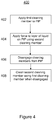
- Figure 4 is a flow diagram showing a method 400 of operating a cleaning station such as the cleaning station 200 described with reference to Figures 2 and 2 , according to an example.
- a first cleaning member for example in the form of sponge 118, is applied to the PIP 102 of the printer to remove particles from the PIP 102.
- a cleaning station is in an engaged position.
- a second cleaning member for example the wiper 120, applies a force to a layer of liquid, such as imaging oil, that is applied to the PIP 102.
- the sponge 118 and wiper 120 are disengaged from the PIP 102. This may be achieved by moving the cleaning station 200 out of contact with the PIP 102 and, during disengaging, moving the wiper 120 into contact with the sponge 118, as explained above with reference to Figures 2 and 3 .
- the cleaning station 200 can be used to automatically clean the wiper 120 before printing starts and after printing has finished, as the biasing member 208 can cause the wiper 120 to contact the sponge 118 during existing engage and disengage sequences.
- the liquid electrophotographic printer has a number of states, such as "off”, “standby”, “get ready” and "print”. To manually clean the wiper 120, the printer is turned off completely. However, the printer need not be turned off in order to automatically clean of the wiper 120 in the disengaged position.
- An example engage sequence for engaging the cleaning station 200 with the PIP 102, includes starting a motor to rotate the sponge 118. Thereafter, the pump 202 is started to apply cleaning fluid (which may also act to cool the PIP 102) to the sponge 118. There is then a wait of an appropriate period of time, for example approximately 4 seconds, to allow the fluid flow to stabilize; this can be referred to as a "pre-printing" stage. It is at this point that the rotating sponge 118 and wiper 120 are in contact while the cleaning station 200 is disengaged from the PIP 102, and there is time for the rotating sponge 118 to clean the wiper 120.
- cleaning fluid which may also act to cool the PIP 102
- pneumatic pistons can push the cleaning station 200 to rotate on the cleaning station axis 218 towards the PIP 102. This moves the cleaning station 200 to the engaged position, the wiper 120 is moved out of contact with the sponge 118 and the sponge 118 and wiper 120 are applied to the PIP 102.
- An example disengage sequence for disengaging the cleaning station 200 with the PIP 102, begins when the pneumatic pistons stop pushing the cleaning station 200 towards the PIP 102, and a retaining spring (not shown) attached to the cleaning station 200 applies a force to rotate the cleaning station 200 on the cleaning station axis 218 to the disengaged position (as shown in Figure 3 ). Thereafter, the pump 202 is turned off to stop the flow of fluid to the sponge 118. There is then a wait of an appropriate period of time, for example approximately 4 seconds, to allow the rotating sponge to dry; this can be referred to as a "post-printing" stage.
- the rotating sponge 118 and wiper 120 are in contact while the cleaning station 200 is disengaged from the PIP 102, and there is time for the rotating sponge 118 to clean the wiper 120. Subsequently, the motor is turned off to stop rotation of the sponge 118. At this point, the printer may be in a "standby" stage.
Landscapes
- Physics & Mathematics (AREA)
- General Physics & Mathematics (AREA)
- Cleaning In Electrography (AREA)
- Ink Jet (AREA)
Description
- Liquid Electro-Photography (LEP) printing devices form images on print media by placing a uniform electrostatic charge on a photoreceptor in the form of a photo imaging plate (PIP) and then selectively discharging the PIP in correspondence with the images. The selective discharging forms a latent electrostatic image on the PIP. Ink comprising charged colorant particles suspended in imaging oil is then developed from a binary ink development (BID) unit on to the latent image formed on the PIP. The image developed on the PIP is offset to an image transfer element comprising a blanket, where it is heated until the solvent evaporates and the resinous colorants melt. This image layer is then transferred to the surface of the print media being supported on a transfer member.
-
US 2012/275836 describes a cleaning apparatus for an image forming apparatus. The cleaning apparatus includes two sponge applicators and a wiping unit. The sponge applicators and the wiping unit are fixed relative to each other in the cleaning apparatus. -
JP H08-6451 -
JP 2006-227130 - Various features of the present disclosure will be apparent from the detailed description which follows, taken in conjunction with the accompanying drawings, which together illustrate features of the present disclosure, and wherein:
-
Figure 1 is a schematic diagram showing a cross section of a print engine in a liquid electrophotographic printer according to an example; -
Figure 2 is a schematic diagram showing a cross section of a cleaning station of a liquid electrophotographic printer in a first position relative to a photo imaging plate of a liquid electrophotographic printer, according to an example; -
Figure 3 is a schematic diagram showing a cross section of the cleaning station ofFigure 2 in a second position relative to the photo imaging plate, according to an example; and -
Figure 4 is a flow diagram showing a method of operating a cleaning station of a liquid electrophotographic printer according to an example. - Certain examples described herein relate to cleaning members for printing devices. For example, certain examples are directed to cleaning members for a photo-imaging member of a printing device. The printing device may be an LEP printing device. In certain cases, the photo-imaging member is a photo imaging plate (PIP), such as is mounted around a rotatable drum or cylinder.
- In certain LEP printing devices, following transfer of ink from the PIP to a transfer member, such as a blanket of a rotating drum, the PIP passes a photo imaging plate cleaning station (referred to hereinafter as a cleaning station) to prepare the surface of the PIP for recharging and for a new latent image to be formed. The cleaning station may act to cool the PIP to a predetermined temperature by supplying cold fluid, such as imaging oil, to the surface of the PIP. The cleaning station may also clean the PIP of any fused ink debris that has become attached to it after being transferred from the blanket, and any un-fused ink that has not passed to the blanket. The cleaning station can have a plurality of cleaning members, such as one or more cleaning sponges to clean residual ink from the surface of the PIP, and one or more wiper blades to remove imaging oil from the surface of the PIP cleaned by the sponge(s) and to thereby control the amount of imaging oil applied to the PIP.
- In certain cases, cleaning fluid, for example in the form of imaging oil, is applied to the sponges and then squeezed out by a separate squeezer to help remove the debris from the sponges. However, if not all of the debris particles are removed, then any remaining particles can, during subsequent rotation of the sponges, scratch a layer of imaging oil that has been deposited on the PIP. Particles may gather under the wiper, causing the removal of, or a change in, the thickness of the layer of imaging oil applied to the PIP in the lateral direction. Each of these changes in the deposited layer of imaging oil can cause a change in the lateral conductivity of the PIP. This may result in a print quality defect called "vertical scratches" or "vertical lines" on the print.
- Certain examples described herein improve a cleaning station of an LEP printer. In examples, the cleaning station has a first cleaning member and a second cleaning member, and is configured to move between a first position and a second position with respect to a photo imaging plate of the printer. In the second position, a biasing member is configured to cause the second cleaning member to contact the first cleaning member to clean the second cleaning member. This can increase the efficiency of debris removal from the second cleaning member, and help to reduce and/or avoid print quality defects.
- In the following description, for purposes of explanation, numerous specific details of certain examples are set forth. Reference in the specification to "an example" or similar language means that a particular feature, structure, or characteristic described in connection with the example is included in at least that one example, but not necessarily in other examples.
-
Figure 1 illustrates example components of aprint engine 100 in a liquid electrophotographic printer (LEP). Theprint engine 100 includes a photo imaging plate 102 (referred to hereinafter as a PIP), a latentimage forming unit 104, and one or more binary ink development units 106 (referred to hereinafter as BID units) to develop an ink image on thePIP 102. Theprint engine 100 ofFigure 1 is shown as an example, other printing devices may vary in form or structure, e.g. a photo imaging member may be planar or part of a belt-driven system. - In the
example print engine 100 ofFigure 1 , a desired image is initially formed as a latent electrostatic image on thePIP 102. For example, an image is formed on thePIP 102 by rotating a clean, bare segment of thePIP 102 under the latentimage forming unit 104. The latentimage forming unit 104 may include a charging device, such as corona wire, charge roller, or other charging device, and a laser imaging portion. A uniform static charge may be deposited on thePIP 102 by the latentimage forming unit 104. As thePIP 102 continues to rotate, a charged portion of thePIP 102 passes the laser imaging portion of the latentimage forming unit 104. The laser imaging unit may dissipate localized charge in selected portions of thePIP 102 to leave a latent electrostatic charge pattern corresponding to an image to be printed. In some examples, the latentimage forming unit 104 applies a negative charge to the surface of thePIP 102. In other examples, the charge may be a positive charge. The laser imaging portion of the latentimage forming unit 104 may then locally discharge portions of thePIP 102, resulting in local neutralized regions on thePIP 102. - During a print cycle, at least one of the
BID units 106 is engaged with thePIP 102. The engaged BID is to apply printing fluid, for example in the form of liquid ink, to thePIP 102. The liquid ink comprises electrically charged ink particles that are attracted to the oppositely charged portions of thePIP 102. The ink particles may be repelled from other areas of thePIP 102. The result is that an image is developed onto the latent electrostatic image provided on thePIP 102. - The
print engine 100 also includes animage transfer member 108. In the Figure, this comprises a drum around which is wrapped ablanket 110, but in other cases may comprise a belt or other transport system. Following development of an image on thePIP 102, thePIP 102 continues to rotate and transfers the printing substance, in the form of the image, to theblanket layer 110. In some examples, theimage transfer member 108 is electrically charged to facilitate transfer of the image to theblanket 110. - The
image transfer member 108 transfers the image from theblanket 110 to asubstrate 112 located between theimage transfer member 108 and animpression cylinder 114. This process may be repeated, if more than one layer is to be included in a final image to be provided on thesubstrate 112. In certain other examples, an image may also be transferred directly from the PIP to the substrate. - Following transfer of ink from the
PIP 102 to theimage transfer member 108, thePIP 102 passes a photo-imaging plate cleaning station 116 (referred to hereinafter as a cleaning station) to prepare the surface of thePIP 102 for recharging and for a new latent image to be formed. The cleaning station can comprise one ormore cleaning sponges 118, to clean residual ink from the surface of the PIP, and one ormore wiper blades 120 to control the amount of imaging oil applied to the PIP. The surface of the PIP may comprise a thin film of conductive material that is referred to as the PIP foil. The thickness of the layer of imaging oil across the surface of the PIP foil affects the lateral conductivity of the PIP foil. Therefore, an even layer of imaging oil across the PIP foil ensures that there is minimal contrast in the lateral conductivity across the PIP foil, resulting in a high quality print. - A print quality defect referred to as "vertical lines" or "vertical scratches", in which the dot area of the printed image changes within a thin vertical area, can occur in LEP printers owing to the presence of an uneven layer of imaging oil over the PIP foil. This can occur for a number of reasons. For example, imaging oil is applied to the sponges and then squeezed out, using a squeezing component, to help remove particles such as fused ink debris from the sponges; however, in practice not all of the debris particles may be removed from the sponges and remaining particles can scratch the deposited layer of imaging oil on the PIP foil during subsequent rotations of the sponges. The scratched area has the original lateral conductivity of the PIP foil, creating a difference between the lateral conductivity of the scratched area and that of the rest of the PIP foil. Particles that have not been removed from the sponges may also gather under the wiper, affecting the wiper's ability to control the thickness of the imaging oil applied to the PIP in the lateral direction, and resulting in an uneven layer and, consequently, areas of contrasting lateral conductivity. Non-uniformity in printed output quality is commonly referred to as OPS (old photoconductor syndrome).
- In order to clean the wiper, the printer is switched off (the wiper being out of contact with the PIP at this stage) and the wiper is manually cleaned with a cloth. The wiper can be removed in order to do this, or cleaned in situ. This occurs at least once a day, for example before the first print of the day, but an operator of the printer can monitor contamination of the wiper over time and may have to turn off the printer in order to clean the wiper multiple times each day.
-
Figure 2 illustrates the components of a cleaningstation 200 in a first, engaged position with respect to the PIP, according to an example. The cleaning station may be used to help alleviate the print quality defects described above. - The cleaning
station 200 comprises a first cleaning member, which may be, for example, asponge 118 that is arranged to remove particles from thePIP 102 of the LEP printer. The first cleaning component is formed of a soft, compressible material, such as a sponge, brush or microcellular (polymer) material that will not damage the PIP during removal of the particles. This material can be glued to a rotatable core, such as a hollow metal cylinder. In the example ofFigure 2 , thesponge 118 andPIP 102 rotate anti-clockwise, but they could alternatively be arranged to both rotate clockwise. InFigure 2 , a single first cleaning component in the form of asingle sponge 118 is shown, but multiple first cleaning components can be provided. As their surfaces pass one another, the sponge collects particles such as ink debris and dust from the surface of thePIP 102. A fluid supply, in the form of apump 202, can apply a cleaning fluid to thesponge 118. The cleaning fluid may be imaging oil. One or more squeezingcomponents 204, such as rotatable squeezers, are arranged to squeeze thesponge 118 in order to remove the cleaning fluid and particles from thesponge 118. Many of the particles can then be flushed from the squeezingcomponents 204 into a cleaning station bath (not shown). The particles are subsequently filtered from the cleaning fluid. In an example in which the cleaning fluid is imaging oil, the filtered imaging oil can be recycled for application to thePIP 102. - The cleaning
station 200 also comprises a second cleaning member, which may be, for example, awiper 120 that is arranged to apply a force to a layer of liquid applied to the photo imaging plate. Thewiper 120 is held by awiper housing 206, which may be formed of aluminium or a similar material by extrusion. Thewiper 120 may be formed of solid polyurethane and is fixed within thewiper housing 206. Thewiper 120 can be configured to have some flexibility when a force is applied to its tip, for example by thePIP 102, such that it exerts a suitable pressure on thePIP 102. - A biasing
member 208, such as a spring or extension spring, is attached between thewiper housing 206 and a fixed part of the cleaningstation 200, such as a cleaningstation housing 210 or an internal component of the cleaningstation 200 that does not move relative to the cleaningstation housing 210. The biasingmember 208 is configured such that, in the engaged position, a force generated by the PIP surface overcomes the biasing force; the force applied by the biasingmember 208 is weaker than the reactive force generated by thePIP 102 surface. Therefore, the presence of the biasingmember 208 does not adversely affect the positioning or functioning of the cleaning station components in the engaged position. Awiper housing axis 212 andstopper members Figure 3 below. As can be seen inFigure 2 , alower stopper member 214 can contact thewiper housing 206 to define a position of thewiper 120 when the cleaningstation 200 is in the engaged position. -
Figure 3 illustrates the components of the cleaningstation 200 ofFigure 2 in a second, disengaged position with respect to the PIP, according to an example. - The cleaning
station 200 is arranged to rotate on acleaning station axis 218 between the first, engaged position as shown inFigure 2 and a second, disengaged position as shown inFigure 3 . In the disengaged position, the components of the cleaningstation 200 such as the first and second cleaning members do not contact thePIP 102. In moving between the engaged and disengaged positions, the entirecleaning station housing 210 is arranged to rotate or pivot about the cleaningstation axis 218. - Referring to
Figure 3 , in the second, disengaged position, the biasingmember 208 is configured to cause the second cleaning member, in the form of thewiper 120, to contact the first cleaning member, in the form of thesponge 118. Thewiper 120 is moveably mounted within the cleaningstation housing 210. For example, thewiper 120 can be configured to pivot about thewiper housing axis 212 so as to contact therotatable sponge 118. In this position, thesponge 118 is able to clean thewiper 120 by rotating against it. Anupper stopper member 216 can contact thewiper housing 206 to define a position of thewiper 120 when the cleaningstation 200 is in the disengaged position. - Therefore, it can be seen from
Figures 2 and3 that the biasingmember 208 allows thewiper 120 to move in and out of contact with therotatable sponge 118 as the cleaningstation 200 moves between the disengaged and engaged positions, respectively. Such a mechanical mechanism allows automatic cleaning of thewiper 120 without the need for an electrical actuator or sensor. In an example, the movement of thewiper 120 is aided by thewiper housing axis 212, about which thewiper housing 212 can pivot, and thelower stopper member 214 andupper stopper member 216, which are arranged to limit the movement of thewiper 120. - As noted with respect to
Figure 2 , a fluid supply, in the form of apump 202, can apply a cleaning fluid to thesponge 118. Therefore, when the cleaning station is in the disengaged position, cleaning fluid fromsponge 118 wets thewiper 120. Applying fluid to the wiper tip in this way reduces the chance of wiper erosion and hence increases the wiper's lifespan. -
Figure 4 is a flow diagram showing amethod 400 of operating a cleaning station such as the cleaningstation 200 described with reference toFigures 2 and 2 , according to an example. - At
block 402, a first cleaning member, for example in the form ofsponge 118, is applied to thePIP 102 of the printer to remove particles from thePIP 102. At this point, a cleaning station is in an engaged position. - At
block 404, a second cleaning member, for example thewiper 120, applies a force to a layer of liquid, such as imaging oil, that is applied to thePIP 102. - At
block 406, thesponge 118 andwiper 120 are disengaged from thePIP 102. This may be achieved by moving the cleaningstation 200 out of contact with thePIP 102 and, during disengaging, moving thewiper 120 into contact with thesponge 118, as explained above with reference toFigures 2 and3 . - At
block 408, when thesponge 118 and thewiper 120 are disengaged from thePIP 102, thesponge 118 is used to clean thewiper 120. - The cleaning
station 200 can be used to automatically clean thewiper 120 before printing starts and after printing has finished, as the biasingmember 208 can cause thewiper 120 to contact thesponge 118 during existing engage and disengage sequences. The liquid electrophotographic printer has a number of states, such as "off", "standby", "get ready" and "print". To manually clean thewiper 120, the printer is turned off completely. However, the printer need not be turned off in order to automatically clean of thewiper 120 in the disengaged position. - An example engage sequence, for engaging the cleaning
station 200 with thePIP 102, includes starting a motor to rotate thesponge 118. Thereafter, thepump 202 is started to apply cleaning fluid (which may also act to cool the PIP 102) to thesponge 118. There is then a wait of an appropriate period of time, for example approximately 4 seconds, to allow the fluid flow to stabilize; this can be referred to as a "pre-printing" stage. It is at this point that therotating sponge 118 andwiper 120 are in contact while the cleaningstation 200 is disengaged from thePIP 102, and there is time for therotating sponge 118 to clean thewiper 120. Subsequently, pneumatic pistons (not shown) can push thecleaning station 200 to rotate on the cleaningstation axis 218 towards thePIP 102. This moves the cleaningstation 200 to the engaged position, thewiper 120 is moved out of contact with thesponge 118 and thesponge 118 andwiper 120 are applied to thePIP 102. - An example disengage sequence, for disengaging the cleaning
station 200 with thePIP 102, begins when the pneumatic pistons stop pushing the cleaningstation 200 towards thePIP 102, and a retaining spring (not shown) attached to the cleaningstation 200 applies a force to rotate the cleaningstation 200 on the cleaningstation axis 218 to the disengaged position (as shown inFigure 3 ). Thereafter, thepump 202 is turned off to stop the flow of fluid to thesponge 118. There is then a wait of an appropriate period of time, for example approximately 4 seconds, to allow the rotating sponge to dry; this can be referred to as a "post-printing" stage. It is at this point that therotating sponge 118 andwiper 120 are in contact while the cleaningstation 200 is disengaged from thePIP 102, and there is time for therotating sponge 118 to clean thewiper 120. Subsequently, the motor is turned off to stop rotation of thesponge 118. At this point, the printer may be in a "standby" stage. - Therefore, there is no need to manually clean the
wiper 120, and the likelihood of particles such as ink debris becoming trapped under thewiper 120, and causing print quality issues, is greatly reduced. - The preceding description has been presented to illustrate and describe examples of the principles described. This description is not intended to be exhaustive or to limit these principles to any precise form disclosed. Many modifications and variations are possible in light of the above teaching. It is to be understood that any feature described in relation to any one example may be used alone, or in combination with other features described, and may also be used in combination with any features of any other of the examples, or any combination of any other of the examples. Examples covered by the present invention are defined by the appended claims.
Claims (15)
- A cleaning station (200) for a liquid electrophotographic printer comprising:a first cleaning member;a second cleaning member; anda biasing member (208),wherein the cleaning station (200) is configured to move between a first position and a second position with respect to a photo imaging member of the printer,wherein:in the first position, the first cleaning member is arranged to remove particles from the photo imaging member of the printer and the second cleaning member is arranged to apply a force to a layer of liquid applied to the photo imaging member; andin the second position, the biasing member (208) is configured to cause the second cleaning member to contact the first cleaning member to clean the second cleaning member.
- The cleaning station (200) of claim 1, wherein the biasing member (208) is configured to cause the second cleaning member to pivot about an axis in order to contact the first cleaning member.
- The cleaning station (200) of claim 1, wherein the biasing member (208) is a spring attached between a fixed part of the cleaning station (200) that does not move relative to a housing (210) of the cleaning station, and the second cleaning
member, the spring being configured to move the second cleaning member in and out of contact with the first cleaning member as the cleaning station (200) moves between the second and first positions, respectively. - The cleaning station (200) of claim 1, wherein the photo imaging member comprises a rotatable drum.
- The cleaning station (200) of claim 1, further comprising a fluid supply arranged to apply cleaning fluid to the first cleaning member such that, when the cleaning station (200) is in the second position, cleaning fluid from the first cleaning member wets the second cleaning member.
- A liquid electrophotographic printer comprising:a photo imaging member; andthe cleaning station according to claim 1, the cleaning station comprising a housing (210);wherein the first cleaning member comprises a rotatable sponge (118) andthe second cleaning member comprises a wiper (120), and wherein the wiper (120) is moveably mounted within the housing (210).
- The liquid electrophotographic printer of claim 6, wherein the wiper (120) is configured to pivot about an axis (212) so as to contact the rotatable sponge (118).
- The liquid electrophotographic printer of claim 6, wherein the biasing member (208) comprises a spring attached between the housing (210) and the wiper (120), the spring being configured to move the wiper (120) in and out of contact with the rotatable sponge (118) as the housing (210) moves between the second position and the first position, respectively.
- The liquid electrophotographic printer of claim 6, wherein the photo imaging member is mounted upon a rotating drum.
- The liquid electrophotographic printer of claim 6, further comprising a fluid supply arranged to apply cleaning fluid to the rotatable sponge (118) such that, when the housing (210) is in the second position, cleaning fluid from the rotatable sponge (118) wets the wiper (120).
- A method of cleaning a liquid electrophotographic printer, the method comprising:applying a first cleaning member to a photo imaging plate of the printer to remove particles from the photo imaging plate (102);applying a force, using a second cleaning member, to a layer of liquid applied to the photo imaging plate (102);disengaging the first and second cleaning members from the photo imaging plate by moving a cleaning station (200) comprising the first cleaning member, the second cleaning member and a biasing member out of contact with the photo
imaging plate (102) and, during said disengaging and by applying a force by the biasing member, moving the second cleaning member into contact with the first cleaning member in order to clean the second cleaning member; andcleaning the second cleaning member using the first cleaning member when in a disengaged position. - The method of claim 11, comprising causing the second cleaning member to pivot about an axis when disengaging the first and second cleaning members from the photo imaging plate (102), in order for the second cleaning member to contact the first cleaning member.
- The method of claim 11, comprising applying cleaning fluid to the first cleaning member such that, when the first and second cleaning members are disengaged, cleaning fluid from the first cleaning member wets the second cleaning member.
- The method of claim 11, wherein the biasing member is attached between a fixed part of the cleaning station (200) that does not move relative to a housing (210) of the cleaning station, and the second cleaning member, and the biasing member moves the second cleaning member in and out of contact with the first cleaning member as the cleaning station moves out of and in contact with the photo imaging plate, respectively.
- The method of claim 11, the method comprising, subsequently to cleaning the second cleaning member using the first cleaning member when in a disengaged position:engaging the first and second cleaning members by moving the cleaning station (200) into contact with the photo imaging plate (102); andduring said engaging, moving the second cleaning member out of contact with the first cleaning member such that the first and second cleaning members are applied to the photo imaging plate (102).
Applications Claiming Priority (1)
| Application Number | Priority Date | Filing Date | Title |
|---|---|---|---|
| PCT/EP2017/076720 WO2019076460A1 (en) | 2017-10-19 | 2017-10-19 | Cleaning a liquid electrophotographic printer |
Publications (2)
| Publication Number | Publication Date |
|---|---|
| EP3676669A1 EP3676669A1 (en) | 2020-07-08 |
| EP3676669B1 true EP3676669B1 (en) | 2021-12-29 |
Family
ID=60190822
Family Applications (1)
| Application Number | Title | Priority Date | Filing Date |
|---|---|---|---|
| EP17791326.6A Not-in-force EP3676669B1 (en) | 2017-10-19 | 2017-10-19 | Cleaning a liquid electrophotographic printer |
Country Status (4)
| Country | Link |
|---|---|
| US (1) | US11249435B2 (en) |
| EP (1) | EP3676669B1 (en) |
| CN (1) | CN111033391B (en) |
| WO (1) | WO2019076460A1 (en) |
Family Cites Families (16)
| Publication number | Priority date | Publication date | Assignee | Title |
|---|---|---|---|---|
| JPH079172Y2 (en) * | 1987-11-12 | 1995-03-06 | 富士ゼロックス株式会社 | Cleaning device |
| JPH0291675A (en) * | 1988-09-29 | 1990-03-30 | Canon Inc | Image forming device cleaning device |
| JPH086451A (en) * | 1994-06-22 | 1996-01-12 | Ricoh Co Ltd | Cleaning device for wet image forming apparatus |
| US6457412B1 (en) | 2000-12-04 | 2002-10-01 | Printing Research, Inc. | Cylinder impurity remover apparatus |
| JP2004138729A (en) * | 2002-10-16 | 2004-05-13 | Kyocera Mita Corp | Cleaning device |
| JP4638179B2 (en) * | 2004-06-14 | 2011-02-23 | 株式会社リコー | Cleaning device and image forming apparatus |
| JP2006227130A (en) * | 2005-02-16 | 2006-08-31 | Ricoh Co Ltd | Cleaning device and image forming apparatus |
| JP2007304334A (en) * | 2006-05-11 | 2007-11-22 | Konica Minolta Business Technologies Inc | Cleaning device for image forming apparatus |
| US7929878B1 (en) | 2009-11-18 | 2011-04-19 | Xerox Corporation | Photoreceptor filming reduction and long photoreceptor life through adjustment of cleaning blade working angle |
| US20120121299A1 (en) * | 2010-11-17 | 2012-05-17 | Rimai Donald S | Removing electrophotographic carrier particles from photoreceptor |
| US8583021B2 (en) * | 2011-04-28 | 2013-11-12 | Hewlett_Packard Indigo B.V. | Image forming apparatus including sponge applicator units to sequentially contact a photoconductive member |
| JP6086297B2 (en) | 2012-01-24 | 2017-03-01 | 株式会社リコー | Cleaning blade, image forming apparatus, and process cartridge |
| JP5722263B2 (en) * | 2012-03-23 | 2015-05-20 | 京セラドキュメントソリューションズ株式会社 | Cleaning device and image forming apparatus |
| US9031470B2 (en) | 2012-06-07 | 2015-05-12 | Hewlett-Packard Indigo B.V. | LEP printer, a photo imaging plate for such printer and a method for wiping such photo imaging plate |
| US9207592B2 (en) * | 2013-01-09 | 2015-12-08 | Sharp Kabushiki Kaisha | Fixing device capable of preventing temperature drop due to heat absorption and image forming apparatus including same |
| US10025256B2 (en) * | 2014-09-18 | 2018-07-17 | Hp Indigo B.V. | Cleaning a silicon photoconductor |
-
2017
- 2017-10-19 US US16/606,211 patent/US11249435B2/en active Active
- 2017-10-19 EP EP17791326.6A patent/EP3676669B1/en not_active Not-in-force
- 2017-10-19 WO PCT/EP2017/076720 patent/WO2019076460A1/en not_active Ceased
- 2017-10-19 CN CN201780094068.2A patent/CN111033391B/en not_active Expired - Fee Related
Also Published As
| Publication number | Publication date |
|---|---|
| US20210278795A1 (en) | 2021-09-09 |
| CN111033391A (en) | 2020-04-17 |
| WO2019076460A1 (en) | 2019-04-25 |
| US11249435B2 (en) | 2022-02-15 |
| EP3676669A1 (en) | 2020-07-08 |
| CN111033391B (en) | 2022-06-03 |
Similar Documents
| Publication | Publication Date | Title |
|---|---|---|
| US11860557B2 (en) | Cleaning surfaces for print apparatus | |
| US9841696B2 (en) | Image forming apparatus and cleaning method | |
| US10866541B2 (en) | Cleaning unit | |
| US10877403B2 (en) | Operating a liquid electrophotographic printer | |
| US11249435B2 (en) | Cleaning a liquid electrophotographic printer | |
| US20200241448A1 (en) | Cleaning station sponges | |
| EP2187269A2 (en) | Electrophotographic printer | |
| JP5752318B2 (en) | Apparatus, printer, and method for removing material from a printer surface | |
| EP3278182B1 (en) | Electrophotographic printing | |
| CN110402419B (en) | Printing fluid developer assembly | |
| WO2017071769A1 (en) | Electro-photographic printing | |
| US6212353B1 (en) | Method and apparatus for cleaning an image transfer member | |
| WO2018169512A1 (en) | Spring in a printing fluid developer | |
| JP6157324B2 (en) | Equipment useful in printing | |
| EP3513252B1 (en) | Transferring print agent to cleanable medium | |
| JPH11327328A (en) | Roller for electrophotographic printer and its production | |
| WO2007050064A1 (en) | Printer photoreceptor maintenance | |
| JP2013003563A (en) | Fixing device and image forming apparatus including the same | |
| JP2006330385A (en) | Image forming apparatus |
Legal Events
| Date | Code | Title | Description |
|---|---|---|---|
| STAA | Information on the status of an ep patent application or granted ep patent |
Free format text: STATUS: UNKNOWN |
|
| STAA | Information on the status of an ep patent application or granted ep patent |
Free format text: STATUS: THE INTERNATIONAL PUBLICATION HAS BEEN MADE |
|
| PUAI | Public reference made under article 153(3) epc to a published international application that has entered the european phase |
Free format text: ORIGINAL CODE: 0009012 |
|
| STAA | Information on the status of an ep patent application or granted ep patent |
Free format text: STATUS: REQUEST FOR EXAMINATION WAS MADE |
|
| 17P | Request for examination filed |
Effective date: 20200330 |
|
| AK | Designated contracting states |
Kind code of ref document: A1 Designated state(s): AL AT BE BG CH CY CZ DE DK EE ES FI FR GB GR HR HU IE IS IT LI LT LU LV MC MK MT NL NO PL PT RO RS SE SI SK SM TR |
|
| AX | Request for extension of the european patent |
Extension state: BA ME |
|
| DAV | Request for validation of the european patent (deleted) | ||
| DAX | Request for extension of the european patent (deleted) | ||
| GRAP | Despatch of communication of intention to grant a patent |
Free format text: ORIGINAL CODE: EPIDOSNIGR1 |
|
| STAA | Information on the status of an ep patent application or granted ep patent |
Free format text: STATUS: GRANT OF PATENT IS INTENDED |
|
| INTG | Intention to grant announced |
Effective date: 20210914 |
|
| GRAS | Grant fee paid |
Free format text: ORIGINAL CODE: EPIDOSNIGR3 |
|
| GRAA | (expected) grant |
Free format text: ORIGINAL CODE: 0009210 |
|
| STAA | Information on the status of an ep patent application or granted ep patent |
Free format text: STATUS: THE PATENT HAS BEEN GRANTED |
|
| AK | Designated contracting states |
Kind code of ref document: B1 Designated state(s): AL AT BE BG CH CY CZ DE DK EE ES FI FR GB GR HR HU IE IS IT LI LT LU LV MC MK MT NL NO PL PT RO RS SE SI SK SM TR |
|
| REG | Reference to a national code |
Ref country code: GB Ref legal event code: FG4D |
|
| REG | Reference to a national code |
Ref country code: CH Ref legal event code: EP |
|
| REG | Reference to a national code |
Ref country code: AT Ref legal event code: REF Ref document number: 1459141 Country of ref document: AT Kind code of ref document: T Effective date: 20220115 |
|
| REG | Reference to a national code |
Ref country code: IE Ref legal event code: FG4D |
|
| REG | Reference to a national code |
Ref country code: DE Ref legal event code: R096 Ref document number: 602017051628 Country of ref document: DE |
|
| REG | Reference to a national code |
Ref country code: LT Ref legal event code: MG9D |
|
| PG25 | Lapsed in a contracting state [announced via postgrant information from national office to epo] |
Ref country code: RS Free format text: LAPSE BECAUSE OF FAILURE TO SUBMIT A TRANSLATION OF THE DESCRIPTION OR TO PAY THE FEE WITHIN THE PRESCRIBED TIME-LIMIT Effective date: 20211229 Ref country code: LT Free format text: LAPSE BECAUSE OF FAILURE TO SUBMIT A TRANSLATION OF THE DESCRIPTION OR TO PAY THE FEE WITHIN THE PRESCRIBED TIME-LIMIT Effective date: 20211229 Ref country code: FI Free format text: LAPSE BECAUSE OF FAILURE TO SUBMIT A TRANSLATION OF THE DESCRIPTION OR TO PAY THE FEE WITHIN THE PRESCRIBED TIME-LIMIT Effective date: 20211229 Ref country code: BG Free format text: LAPSE BECAUSE OF FAILURE TO SUBMIT A TRANSLATION OF THE DESCRIPTION OR TO PAY THE FEE WITHIN THE PRESCRIBED TIME-LIMIT Effective date: 20220329 |
|
| REG | Reference to a national code |
Ref country code: NL Ref legal event code: MP Effective date: 20211229 |
|
| REG | Reference to a national code |
Ref country code: AT Ref legal event code: MK05 Ref document number: 1459141 Country of ref document: AT Kind code of ref document: T Effective date: 20211229 |
|
| PG25 | Lapsed in a contracting state [announced via postgrant information from national office to epo] |
Ref country code: SE Free format text: LAPSE BECAUSE OF FAILURE TO SUBMIT A TRANSLATION OF THE DESCRIPTION OR TO PAY THE FEE WITHIN THE PRESCRIBED TIME-LIMIT Effective date: 20211229 Ref country code: NO Free format text: LAPSE BECAUSE OF FAILURE TO SUBMIT A TRANSLATION OF THE DESCRIPTION OR TO PAY THE FEE WITHIN THE PRESCRIBED TIME-LIMIT Effective date: 20220329 Ref country code: LV Free format text: LAPSE BECAUSE OF FAILURE TO SUBMIT A TRANSLATION OF THE DESCRIPTION OR TO PAY THE FEE WITHIN THE PRESCRIBED TIME-LIMIT Effective date: 20211229 Ref country code: HR Free format text: LAPSE BECAUSE OF FAILURE TO SUBMIT A TRANSLATION OF THE DESCRIPTION OR TO PAY THE FEE WITHIN THE PRESCRIBED TIME-LIMIT Effective date: 20211229 Ref country code: GR Free format text: LAPSE BECAUSE OF FAILURE TO SUBMIT A TRANSLATION OF THE DESCRIPTION OR TO PAY THE FEE WITHIN THE PRESCRIBED TIME-LIMIT Effective date: 20220330 |
|
| PG25 | Lapsed in a contracting state [announced via postgrant information from national office to epo] |
Ref country code: NL Free format text: LAPSE BECAUSE OF FAILURE TO SUBMIT A TRANSLATION OF THE DESCRIPTION OR TO PAY THE FEE WITHIN THE PRESCRIBED TIME-LIMIT Effective date: 20211229 |
|
| PG25 | Lapsed in a contracting state [announced via postgrant information from national office to epo] |
Ref country code: SM Free format text: LAPSE BECAUSE OF FAILURE TO SUBMIT A TRANSLATION OF THE DESCRIPTION OR TO PAY THE FEE WITHIN THE PRESCRIBED TIME-LIMIT Effective date: 20211229 Ref country code: SK Free format text: LAPSE BECAUSE OF FAILURE TO SUBMIT A TRANSLATION OF THE DESCRIPTION OR TO PAY THE FEE WITHIN THE PRESCRIBED TIME-LIMIT Effective date: 20211229 Ref country code: RO Free format text: LAPSE BECAUSE OF FAILURE TO SUBMIT A TRANSLATION OF THE DESCRIPTION OR TO PAY THE FEE WITHIN THE PRESCRIBED TIME-LIMIT Effective date: 20211229 Ref country code: PT Free format text: LAPSE BECAUSE OF FAILURE TO SUBMIT A TRANSLATION OF THE DESCRIPTION OR TO PAY THE FEE WITHIN THE PRESCRIBED TIME-LIMIT Effective date: 20220429 Ref country code: ES Free format text: LAPSE BECAUSE OF FAILURE TO SUBMIT A TRANSLATION OF THE DESCRIPTION OR TO PAY THE FEE WITHIN THE PRESCRIBED TIME-LIMIT Effective date: 20211229 Ref country code: EE Free format text: LAPSE BECAUSE OF FAILURE TO SUBMIT A TRANSLATION OF THE DESCRIPTION OR TO PAY THE FEE WITHIN THE PRESCRIBED TIME-LIMIT Effective date: 20211229 Ref country code: CZ Free format text: LAPSE BECAUSE OF FAILURE TO SUBMIT A TRANSLATION OF THE DESCRIPTION OR TO PAY THE FEE WITHIN THE PRESCRIBED TIME-LIMIT Effective date: 20211229 |
|
| PG25 | Lapsed in a contracting state [announced via postgrant information from national office to epo] |
Ref country code: PL Free format text: LAPSE BECAUSE OF FAILURE TO SUBMIT A TRANSLATION OF THE DESCRIPTION OR TO PAY THE FEE WITHIN THE PRESCRIBED TIME-LIMIT Effective date: 20211229 Ref country code: AT Free format text: LAPSE BECAUSE OF FAILURE TO SUBMIT A TRANSLATION OF THE DESCRIPTION OR TO PAY THE FEE WITHIN THE PRESCRIBED TIME-LIMIT Effective date: 20211229 |
|
| PG25 | Lapsed in a contracting state [announced via postgrant information from national office to epo] |
Ref country code: IS Free format text: LAPSE BECAUSE OF FAILURE TO SUBMIT A TRANSLATION OF THE DESCRIPTION OR TO PAY THE FEE WITHIN THE PRESCRIBED TIME-LIMIT Effective date: 20220429 |
|
| REG | Reference to a national code |
Ref country code: DE Ref legal event code: R097 Ref document number: 602017051628 Country of ref document: DE |
|
| PG25 | Lapsed in a contracting state [announced via postgrant information from national office to epo] |
Ref country code: DK Free format text: LAPSE BECAUSE OF FAILURE TO SUBMIT A TRANSLATION OF THE DESCRIPTION OR TO PAY THE FEE WITHIN THE PRESCRIBED TIME-LIMIT Effective date: 20211229 Ref country code: AL Free format text: LAPSE BECAUSE OF FAILURE TO SUBMIT A TRANSLATION OF THE DESCRIPTION OR TO PAY THE FEE WITHIN THE PRESCRIBED TIME-LIMIT Effective date: 20211229 |
|
| PLBE | No opposition filed within time limit |
Free format text: ORIGINAL CODE: 0009261 |
|
| STAA | Information on the status of an ep patent application or granted ep patent |
Free format text: STATUS: NO OPPOSITION FILED WITHIN TIME LIMIT |
|
| 26N | No opposition filed |
Effective date: 20220930 |
|
| PG25 | Lapsed in a contracting state [announced via postgrant information from national office to epo] |
Ref country code: SI Free format text: LAPSE BECAUSE OF FAILURE TO SUBMIT A TRANSLATION OF THE DESCRIPTION OR TO PAY THE FEE WITHIN THE PRESCRIBED TIME-LIMIT Effective date: 20211229 |
|
| PG25 | Lapsed in a contracting state [announced via postgrant information from national office to epo] |
Ref country code: MC Free format text: LAPSE BECAUSE OF FAILURE TO SUBMIT A TRANSLATION OF THE DESCRIPTION OR TO PAY THE FEE WITHIN THE PRESCRIBED TIME-LIMIT Effective date: 20211229 Ref country code: IT Free format text: LAPSE BECAUSE OF FAILURE TO SUBMIT A TRANSLATION OF THE DESCRIPTION OR TO PAY THE FEE WITHIN THE PRESCRIBED TIME-LIMIT Effective date: 20211229 |
|
| REG | Reference to a national code |
Ref country code: CH Ref legal event code: PL |
|
| REG | Reference to a national code |
Ref country code: BE Ref legal event code: MM Effective date: 20221031 |
|
| PG25 | Lapsed in a contracting state [announced via postgrant information from national office to epo] |
Ref country code: LU Free format text: LAPSE BECAUSE OF NON-PAYMENT OF DUE FEES Effective date: 20221019 |
|
| PG25 | Lapsed in a contracting state [announced via postgrant information from national office to epo] |
Ref country code: LI Free format text: LAPSE BECAUSE OF NON-PAYMENT OF DUE FEES Effective date: 20221031 Ref country code: CH Free format text: LAPSE BECAUSE OF NON-PAYMENT OF DUE FEES Effective date: 20221031 |
|
| PG25 | Lapsed in a contracting state [announced via postgrant information from national office to epo] |
Ref country code: BE Free format text: LAPSE BECAUSE OF NON-PAYMENT OF DUE FEES Effective date: 20221031 |
|
| PG25 | Lapsed in a contracting state [announced via postgrant information from national office to epo] |
Ref country code: IE Free format text: LAPSE BECAUSE OF NON-PAYMENT OF DUE FEES Effective date: 20221019 |
|
| PGFP | Annual fee paid to national office [announced via postgrant information from national office to epo] |
Ref country code: GB Payment date: 20230920 Year of fee payment: 7 |
|
| PGFP | Annual fee paid to national office [announced via postgrant information from national office to epo] |
Ref country code: FR Payment date: 20230920 Year of fee payment: 7 |
|
| PGFP | Annual fee paid to national office [announced via postgrant information from national office to epo] |
Ref country code: DE Payment date: 20230920 Year of fee payment: 7 |
|
| PG25 | Lapsed in a contracting state [announced via postgrant information from national office to epo] |
Ref country code: HU Free format text: LAPSE BECAUSE OF FAILURE TO SUBMIT A TRANSLATION OF THE DESCRIPTION OR TO PAY THE FEE WITHIN THE PRESCRIBED TIME-LIMIT; INVALID AB INITIO Effective date: 20171019 |
|
| PG25 | Lapsed in a contracting state [announced via postgrant information from national office to epo] |
Ref country code: CY Free format text: LAPSE BECAUSE OF FAILURE TO SUBMIT A TRANSLATION OF THE DESCRIPTION OR TO PAY THE FEE WITHIN THE PRESCRIBED TIME-LIMIT Effective date: 20211229 |
|
| PG25 | Lapsed in a contracting state [announced via postgrant information from national office to epo] |
Ref country code: MK Free format text: LAPSE BECAUSE OF FAILURE TO SUBMIT A TRANSLATION OF THE DESCRIPTION OR TO PAY THE FEE WITHIN THE PRESCRIBED TIME-LIMIT Effective date: 20211229 |
|
| PG25 | Lapsed in a contracting state [announced via postgrant information from national office to epo] |
Ref country code: TR Free format text: LAPSE BECAUSE OF FAILURE TO SUBMIT A TRANSLATION OF THE DESCRIPTION OR TO PAY THE FEE WITHIN THE PRESCRIBED TIME-LIMIT Effective date: 20211229 |
|
| PG25 | Lapsed in a contracting state [announced via postgrant information from national office to epo] |
Ref country code: MT Free format text: LAPSE BECAUSE OF FAILURE TO SUBMIT A TRANSLATION OF THE DESCRIPTION OR TO PAY THE FEE WITHIN THE PRESCRIBED TIME-LIMIT Effective date: 20211229 |
|
| REG | Reference to a national code |
Ref country code: DE Ref legal event code: R119 Ref document number: 602017051628 Country of ref document: DE |
|
| GBPC | Gb: european patent ceased through non-payment of renewal fee |
Effective date: 20241019 |
|
| PG25 | Lapsed in a contracting state [announced via postgrant information from national office to epo] |
Ref country code: DE Free format text: LAPSE BECAUSE OF NON-PAYMENT OF DUE FEES Effective date: 20250501 |
|
| PG25 | Lapsed in a contracting state [announced via postgrant information from national office to epo] |
Ref country code: GB Free format text: LAPSE BECAUSE OF NON-PAYMENT OF DUE FEES Effective date: 20241019 |
|
| PG25 | Lapsed in a contracting state [announced via postgrant information from national office to epo] |
Ref country code: FR Free format text: LAPSE BECAUSE OF NON-PAYMENT OF DUE FEES Effective date: 20241031 |