EP3676648B1 - Teleskop mit verbesserter leistung - Google Patents
Teleskop mit verbesserter leistung Download PDFInfo
- Publication number
- EP3676648B1 EP3676648B1 EP18758609.4A EP18758609A EP3676648B1 EP 3676648 B1 EP3676648 B1 EP 3676648B1 EP 18758609 A EP18758609 A EP 18758609A EP 3676648 B1 EP3676648 B1 EP 3676648B1
- Authority
- EP
- European Patent Office
- Prior art keywords
- mirror
- primary
- sleeve
- telescope
- primary mirror
- Prior art date
- Legal status (The legal status is an assumption and is not a legal conclusion. Google has not performed a legal analysis and makes no representation as to the accuracy of the status listed.)
- Active
Links
Images



Classifications
-
- G—PHYSICS
- G02—OPTICS
- G02B—OPTICAL ELEMENTS, SYSTEMS OR APPARATUS
- G02B17/00—Systems with reflecting surfaces, with or without refracting elements
- G02B17/02—Catoptric systems, e.g. image erecting and reversing system
- G02B17/06—Catoptric systems, e.g. image erecting and reversing system using mirrors only, i.e. having only one curved mirror
- G02B17/0605—Catoptric systems, e.g. image erecting and reversing system using mirrors only, i.e. having only one curved mirror using two curved mirrors
- G02B17/061—Catoptric systems, e.g. image erecting and reversing system using mirrors only, i.e. having only one curved mirror using two curved mirrors on-axis systems with at least one of the mirrors having a central aperture
-
- G—PHYSICS
- G02—OPTICS
- G02B—OPTICAL ELEMENTS, SYSTEMS OR APPARATUS
- G02B23/00—Telescopes, e.g. binoculars; Periscopes; Instruments for viewing the inside of hollow bodies; Viewfinders; Optical aiming or sighting devices
- G02B23/02—Telescopes, e.g. binoculars; Periscopes; Instruments for viewing the inside of hollow bodies; Viewfinders; Optical aiming or sighting devices involving prisms or mirrors
-
- G—PHYSICS
- G02—OPTICS
- G02B—OPTICAL ELEMENTS, SYSTEMS OR APPARATUS
- G02B23/00—Telescopes, e.g. binoculars; Periscopes; Instruments for viewing the inside of hollow bodies; Viewfinders; Optical aiming or sighting devices
- G02B23/16—Housings; Caps; Mountings; Supports, e.g. with counterweight
-
- G—PHYSICS
- G02—OPTICS
- G02B—OPTICAL ELEMENTS, SYSTEMS OR APPARATUS
- G02B7/00—Mountings, adjusting means, or light-tight connections, for optical elements
- G02B7/18—Mountings, adjusting means, or light-tight connections, for optical elements for prisms; for mirrors
- G02B7/181—Mountings, adjusting means, or light-tight connections, for optical elements for prisms; for mirrors with means for compensating for changes in temperature or for controlling the temperature; thermal stabilisation
-
- G—PHYSICS
- G02—OPTICS
- G02B—OPTICAL ELEMENTS, SYSTEMS OR APPARATUS
- G02B7/00—Mountings, adjusting means, or light-tight connections, for optical elements
- G02B7/18—Mountings, adjusting means, or light-tight connections, for optical elements for prisms; for mirrors
- G02B7/182—Mountings, adjusting means, or light-tight connections, for optical elements for prisms; for mirrors for mirrors
-
- G—PHYSICS
- G02—OPTICS
- G02B—OPTICAL ELEMENTS, SYSTEMS OR APPARATUS
- G02B7/00—Mountings, adjusting means, or light-tight connections, for optical elements
- G02B7/18—Mountings, adjusting means, or light-tight connections, for optical elements for prisms; for mirrors
- G02B7/182—Mountings, adjusting means, or light-tight connections, for optical elements for prisms; for mirrors for mirrors
- G02B7/183—Mountings, adjusting means, or light-tight connections, for optical elements for prisms; for mirrors for mirrors specially adapted for very large mirrors, e.g. for astronomy, or solar concentrators
Definitions
- the present invention relates to the field of optics and more particularly to a telescope usable for observation and aiming.
- a telescope comprises a frame carrying a primary mirror and a secondary mirror held opposite the primary mirror by a support in such a way that the primary mirror reflects the light flux towards the secondary mirror which in turn reflects it towards an eyepiece.
- the frame comprises a plate for fixing the primary mirror so as to maintain in position, relative to the eyepiece, the primary mirror, support, secondary mirror assembly without generating mechanical stresses on the primary mirror.
- Cassegrain telescopes There are many types of telescopes, including Newtonian telescopes and Cassegrain telescopes.
- Cassegrain and related telescopes Schot Cassegrain, Maksutov Cassegrain
- the primary mirror is pierced in its center to allow the light flux returned by the secondary mirror to pass through to an eyepiece placed behind the primary mirror.
- the eyepiece In telescopes used in vehicle-mounted observation and sighting systems, the eyepiece is replaced by a sensor connected to a viewing device mounted in the vehicle's cockpit.
- the quality of the telescope depends on the relative positioning of the mirrors and the deformations undergone by the mirrors.
- One aim of the invention is to improve the performance of telescopes.
- a telescope according to claim 1 is provided.
- the arms then make it possible to maintain the secondary mirror in position relative to the primary mirror, by limiting, on the one hand, the transmission of vibrations to the secondary mirror and, on the other hand, to limit the area of the primary mirror which is masked by the arms with respect to an incident light flux.
- the curvature of the arms makes it possible to limit the influence, on the secondary mirror, of stresses resulting from an expansion of the arms.
- the arms have a first end adjacent to the primary crown and a second end adjacent to the secondary crown, the first end extending radially relative to the primary crown and the second end extending tangentially relative to the secondary crown.
- the primary mirror is connected to the plate by fixing elements each having a base fixed to the plate and, opposite the base, a bearing which is housed between a first rear portion and a second rear portion of the primary mirror and which receives a third section of an axis having a first section and a second section received respectively in a first bore and a second bore which are provided in the first rear portion and the second rear portion respectively.
- the third section is received in the bearing with a sliding fit and is glued into the bearing by means of a structural glue and the axis is provided with a central channel having a first end opening onto a portion of the axis accessible when the axis is in position in the holes to receive one end of a glue injection cannula and a second end opening into at least one transverse channel of which at least one end opens onto an external surface of the third section.
- the support comprises a means of mechanical decoupling of the secondary mirror with respect to the primary mirror and, preferably, the secondary crown comprises an external crown and an internal crown coaxial with the external crown and connected to the latter by symmetrically distributed mechanical decoupling elements.
- the secondary mirror is received with play in the internal crown and is glued therein by means of a structural glue; the external crown comprising third through-holes and the internal crown comprising fourth through-holes substantially aligned with the third holes to allow the introduction of a glue injection cannula.
- a mechanical decoupling means such as the arrangement of the secondary crown of the support makes it possible to limit the transmission of vibrations to the secondary mirror, which significantly improves the performance of the telescope, particularly when it is mounted on a vehicle.
- the telescope is of the Cassegrain type and the plate has a rear surface comprising references of positioning of the telescope relative to an image capture device arranged opposite the rear face.
- the positioning references are obtained by optical quality machining and comprise a face perpendicular to an optical axis of the telescope to form a tilt reference, a central bore to form a centering reference and a concave spherical cap machining having a center on the optical axis to define a distance of the sensor relative to the secondary mirror.
- the secondary mirror comprises, opposite the primary mirror, a central portion provided with at least one engraving for centering the secondary mirror relative to the primary mirror.
- the invention is here described in application with a Maksutov Cassegrain type telescope.
- the primary mirror, the secondary mirror and the support respectively bear the general references 100, 200, 300 in the figures.
- the secondary mirror 200 comprises a body of revolution 201 having a central axis on which are centered a reflecting surface 202, a face 203 opposite the reflecting surface 202, and a peripheral surface 204 of cylindrical shape.
- the reflecting surface 202 has a convex aspherical cap shape which faces the reflecting surface 102 of the primary mirror 100.
- the central axis of the secondary mirror 200 is aligned with the central axis of the primary mirror 100 to define the optical axis A of the telescope.
- the primary mirror 100, the secondary mirror 200 and the support 300 are here made of aluminum.
- the primary mirror 100 is mounted on a fixing plate, generally designated 1, on which the support 300 is fixed.
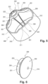
- the support 300 comprises a primary crown 310 mounted on the fixing plate 1 to extend around the primary mirror 100, a secondary crown 320 mounted around the secondary mirror 200, and arms 350 connecting the secondary crown 320 to the primary crown 310.
- the support 300 is here in one piece.
- the primary crown 310 extends around the primary mirror 1 without touching it and comprises an edge 313 enclosing the fixing plate 1 to ensure its fixing to the fixing plate 1.
- the primary crown 310 is here fixed to the fixing plate 1 by gluing using of a structural glue here an epoxy glue.
- the primary crown 310 has an edge 311 extending in projection from the primary mirror 100 on the side of the secondary mirror 200 and the edge 311 is provided with notches 312 making it possible to limit as much as possible the part of the primary crown 310 which extends in projection from the primary mirror 100 and which risks intercepting a secondary light flux oriented towards the primary mirror 100.
- the arms 350 have a first end 351 connecting to the primary ring 310 substantially radially and a second end 352 connecting to the secondary ring 320 substantially tangentially.
- the arms 350 are arranged in three pairs positioned at 120° from each other.
- the first ends 351 are integral with the internal surface 313 of the part of the primary ring 310 extending in projection from the reflecting surface 102, at the level of the non-notched portions.
- the arms 350 of each pair diverge from each other so that the second end 352 of each of the arms 350 of a pair almost joins the second end 352 of the adjacent arm 350 belonging to another pair of arms 350.
- the arms 350 are curved toward the primary mirror 100. More specifically, the arms 350 are curved toward the primary mirror in the sense that the arms have a convex portion on the primary mirror side (expressed differently, the arms have an extrados oriented toward the primary mirror).
- Each arm 350 has a cross-section that varies between the ends 351 and 352 in such a way that, for a given force generating stresses in the branch, the stresses are distributed equivalently along the arm 350.
- the cross-section here has a rectangular shape having a major axis parallel to the optical axis A.
- the support 300 comprises a means of mechanical decoupling of the secondary mirror 200 from the primary mirror 100.
- the secondary crown 320 comprises an external crown 321 to which the second ends 352 of the arms 350 are connected and an internal crown 322 coaxial with the external crown 321 and connected thereto by symmetrically distributed mechanical decoupling elements.
- the mechanical decoupling elements are here formed of three elastic blades 323 extending radially between the external crown 321 and the internal crown 322.
- the elastic blades 323 are arranged at 120° so that each elastic blade 323 is positioned symmetrically between two pairs of arms 350.
- Each elastic blade 323 is arranged to be relatively rigid in a direction parallel to the optical axis A but relatively flexible in a circumferential direction of the secondary crown 200.
- the outer ring 321 comprises third through-bores 331 and the inner ring 322 comprises fourth through-bores 332 which are substantially aligned with the bores 331.
- Each bore 331 and the bore 332 which is aligned with it form a pair of bores allowing the introduction of a glue injection cannula C from the outside of the outer ring 321.
- the bore 331 is arranged to guide the cannula towards the bore 332.
- Each bore 332 is stepped to form a stop for the insertion of the cannula into the bore 332 and is arranged to ensure a sealed connection with the cannula C.
- each bore 332 has an inlet section having a diameter slightly smaller than the diameter of the end of the cannula C slightly set back (1 or 2 mm) from its end so as to grip the latter (see in particular the figure 8 ).
- the secondary mirror 200 is received in the inner ring 322 with a radial clearance of approximately 0.25 mm and is glued therein using a structural glue.
- the positioning of the pairs of holes 331, 332 allows a homogeneous distribution of the glue around the secondary mirror 200.
- the small clearance between the inner surface of the inner ring 322 and the peripheral surface 204 of the secondary mirror 200 allows, on the one hand, to adjust the position (inclination and coaxiality) of the secondary mirror 200 relative to the axis of the primary mirror 100 and, on the other hand, to limit the thickness of glue extending between these two surfaces.
- Have a relatively small thickness allows to limit the constraints that the glue can exert on the secondary mirror 200 due to a thermal variation.
- the glue used here is an epoxy glue and, for example, that of the 3M brand bearing the reference DP490.
- the external crown 321 comprises an internal surface provided with an annular recess 324 so as not to interfere with the secondary mirror 200 during the operations of adjusting the position of said secondary mirror 200.
- the plate 1 has a shape of revolution around a central axis collinear with the optical axis of the telescope and comprises a front face 2 facing the fixing face 103 of the primary mirror 100 and, opposite the latter, a rear surface bearing the general reference 3 on the figure 1 .
- the front face 2 is provided with a circular groove 4 centered on the central axis of the fixing plate 1.
- the groove 4 has a flat bottom on which are fixed fixing elements 10 each having a base 11 resting flat on the bottom of the groove 4 and, opposite the base 11, a bearing 12 which extends projecting from the front face 2.
- the bearing 12 is connected to the base 11 by two connecting rods 13 arranged in a triangle with the base 11.
- the connecting rods 13 are in one piece with the bearing 12 and the base 11.
- the fixing elements 10 are three in number, arranged at 120° to each other symmetrically with respect to the central axis.
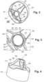
- each fixing element 10 is housed in the groove 107 between the external annular portion 108 and the intermediate annular portion 109.
- Each bearing 12 receives a third section 23 of an axis, generally designated 20 in the figures, having a first section 21 and a second section 22 received respectively in a first drilling 38 and a second drilling 39 which are provided in the external annular portion 108 and the intermediate annular portion 109.
- the drillings 38 and 39 are through holes.
- the second section 22 has a smaller diameter than the third section 23 and is connected to the latter by a shoulder forming a stop for the insertion of the second section 22 into the second bore 39.
- the first section 21 has a larger diameter than the third section 23.
- the first section 21 and the second section 22 are glued respectively in the first bore 38 and the second bore 39 by means of an anaerobic structural glue.
- the glue used is more particularly that of the LOCTITE brand bearing the reference 638. It is advantageous that the smallest possible space is left between the external surface of the sections 21 and 22 on the one hand and the internal surface of the bores 38, 39. The smallest possible space must be sufficient to allow the relative sliding of the two surfaces before bonding and to admit a quantity of glue just sufficient to fix the two surfaces to each other taking into account the forces to be supported.
- the fluidity of the glue influences the dimensioning of this space since the more fluid the glue, the smaller the thickness of the space can be. It is understood that we seek to minimize this thickness and therefore the quantity of glue so that, in the event of a temperature variation, the glue does not generate stresses on the primary mirror 100 likely to deform it.
- the third section 23 is received in the bearing 12 with a sliding fit.
- the sliding fit is here of type H7g6 but could be of type H7g5 or any other sliding fit leaving the smallest possible space between the external surface of the third section 23 and the internal surface of the bearing 12.
- the third section 23 is bonded in the bearing 12 by means of a structural adhesive injected into the central channel 25 then the transverse channel 27 by means of the cannula C introduced into an inlet section of the central channel 25 opening onto the end face 26.
- the adhesive used is more particularly an epoxy structural adhesive and for example that of the 3M brand bearing the reference DP490.
- the smallest possible space left between the external surface of the third section 23 and the internal surface of the bearing 12 must be sufficient to allow the relative sliding of the two surfaces before bonding and to admit a quantity of adhesive just sufficient to fix the two surfaces to each other taking into account the forces to be supported.
- the fluidity of the glue influences this space since the more fluid the glue is, the less thick the space can be. It is understood that we seek to minimize this thickness and therefore the quantity of glue so that, in the event of a temperature variation, the glue does not generate stresses on the primary mirror 100 that could deform it.
- Each of the holes 39 opens on the side of the annular groove 107 into a recess 40 formed in the intermediate annular portion 109 to avoid contact between the bearing 12 and a surface of the intermediate annular portion 109.
- the connecting rods 13 are arranged to ensure mechanical decoupling of the primary mirror 100 and of the fixing plate 1 so as to support the primary mirror 100 while limiting the creation of mechanical stresses in the primary mirror 100.
- the connecting rods 13 comprise parts of reduced thickness in a direction perpendicular to the optical axis and to their longitudinal axis such that the connecting rods are more rigid under forces parallel to the optical axis A than under forces perpendicular to the optical axis A and to their longitudinal axis.
- mirrors 100 and 200, support 300 and plate 1 The assembly of mirrors 100 and 200, support 300 and plate 1 is carried out as follows.
- each fixing element 10 is first fixed to the plate 1 by means of screwed elements not visible in the figures.
- the mirror 100 is then fixed to the fixing elements 10.
- the bearings 12 are engaged in the groove 107 and each axis 20 is successively engaged in the bore 38, the bearing 12 and the bore 39 after the anaerobic structural glue has been deposited on the first section 21 and the second section 22.
- the epoxy structural glue is then introduced between the internal surface of the bearing 12 and the external surface of the third section 23 via the central channel 25 then the transverse channel 27.
- the support 300 is then glued to the plate 1 then the secondary mirror 200 is glued to the support 300 as indicated above.
- the rear surface 3 of the fixing plate 1 includes references for positioning the telescope relative to an image capture assembly symbolized at 400 on the figure 1 arranged opposite the rear face 3.
- the image capture assembly 400 comprises a sensor and possibly one or more lenses mounted in front of the sensor.
- the sensor is positioned parallel to the rear surface 3 and so that the focal point defined by the concave surface portion 53 coincides with that of the sensor.
- the reflecting surface of the secondary mirror 200 comprises a central portion provided with at least one engraving 210 for centering the secondary mirror 200 relative to the primary mirror 100.
- the engraving 210 is in the form of a ring centered on an optical axis of the secondary mirror.
- the adjustment of the positioning of the secondary mirror 200 relative to the primary mirror 100 is carried out, before bonding, by optical interferometry between the surfaces 202 and 102, by moving the secondary mirror 200 using micro-actuators.
- the axis may be mounted cantilevered from a single rear portion of the primary mirror.
- the telescope of the invention performs extremely well when the four features of the invention are combined as in the described embodiment, the four features are independent of each other and it is possible to carry out the invention using only the features of claim 1 or in combination with one or two of the remaining features.
- the means of mechanical decoupling of the secondary mirror 200 with respect to the primary mirror 100 is provided by the arrangement of the secondary crown 320 in two crowns 321, 322 connected to each other by elastic blades 323, other embodiments of this mechanical decoupling means are conceivable.
- a mechanical decoupling means such as an elastic blade, could be interposed between each first end 351 of arm 350 and the primary crown 310.
- the secondary mirror can be attached to the secondary crown in a different way than described.
- the fixing of the primary mirror on the plate can be carried out differently.
- the fixing elements 10 can have a different shape from that described and the axes 20 can be smooth or cantilevered.
- the number of fasteners 10 may be different from three. Each fastener may be in several pieces.
- the primary crown can be fixed differently on the plate, for example glued.
- the transverse channel 27 may have only one end opening onto the external surface of the third section 23 and there may be several transverse channels 27, for example three at 120° from each other.
- the rear face of the plate may not include positioning references or only part of them.
- the invention is applicable to other types of telescope and for example a Schmidt Cassegrain type telescope.
Landscapes
- Physics & Mathematics (AREA)
- General Physics & Mathematics (AREA)
- Optics & Photonics (AREA)
- Astronomy & Astrophysics (AREA)
- Life Sciences & Earth Sciences (AREA)
- Sustainable Development (AREA)
- Telescopes (AREA)
Claims (21)
- Teleskop mit einer Befestigungsplatte (1), einem Primärspiegel (100), der von einer Vorderseite (2) der Platte getragen wird, und einem Sekundärspiegel (200), der dem Primärspiegel gegenüberliegend von einem Träger (300) in Position gehalten wird, dadurch gekennzeichnet, dass der Träger (300) Folgendes umfasst: einen Primärkranz (310), der sich um den Primärspiegel (100) herum erstreckt, ohne den Primärspiegel zu berühren; einen Sekundärkranz (320), der um den Sekundärspiegel (200) herum montiert ist; und Arme (350), die den Sekundärkranz mit dem Primärkranz verbinden; und dass die Arme (350) derart zum Primärspiegel (100) hin gekrümmt sind, dass die Arme einen konvexen Abschnitt auf der Seite des Primärspiegels haben, dass die Arme ein erstes Ende (351) benachbart zum Primärkranz (310) und ein zweites Ende (352) benachbart zum Sekundärkranz (320) haben, und dass jeder Arm (350) einen Querschnitt aufweist, der zwischen den Enden (351, 352) derart variiert, dass für eine gegebene Kraft, welche Spannungen in dem Arm erzeugt, die Spannungen gleichmäßig entlang dem Arm verteilt sind.
- Teleskop nach Anspruch 1, wobei der Primärspiegel mit der Platte durch Befestigungselemente (10) verbunden ist, die jeweils eine an der Platte befestigte Basis (11) und, auf der gegenüberliegenden Seite der Basis, ein Lager (12) aufweisen, das zwischen einem ersten hinteren Abschnitt (108) und einem zweiten hinteren Abschnitt (109) des Primärspiegels untergebracht ist und das einen dritten Abschnitt (23) eines Bolzens (20) aufnimmt, der einen ersten Abschnitt (21) und einen zweiten Abschnitt (22) aufweist, welche jeweils in einer ersten Bohrung (38) und in einer zweiten Bohrung (39) aufgenommen sind, die in dem ersten hinteren Abschnitt bzw. in dem zweiten hinteren Abschnitt ausgebildet sind; wobei der dritte Abschnitt mit einem Gleitsitz in dem Lager aufgenommen ist und mittels eines Strukturklebers in das Lager eingeklebt ist; und wobei der Bolzen Folgendes aufweist: einen Mittelkanal (25) mit einem ersten Ende, das in einen Abschnitt (26) des Bolzens mündet, der zugänglich ist, wenn der Bolzen in den Bohrungen positioniert ist, um ein Ende einer Klebstoff-Injektionskanüle aufzunehmen, und mit einem zweiten Ende, das in zumindest einen Querkanal (27) mündet, von dem zumindest ein Ende in die Außenfläche des dritten Abschnitts mündet.
- Teleskop nach Anspruch 2, wobei der zweite Abschnitt (22) einen geringeren Durchmesser als der dritte Abschnitt (23) hat und mit diesem durch eine Schulter verbunden ist, die einen Tiefenanschlag für die Einbringung des zweiten Abschnitts in die zweite Bohrung (39) bildet.
- Teleskop nach Anspruch 3, wobei es sich bei der zweiten Bohrung (39) um eine Durchgangsbohrung handelt.
- Teleskop nach Anspruch 3, wobei der erste Abschnitt (21) einen größeren Durchmesser als der dritte Abschnitt (23) aufweist.
- Teleskop nach einem der Ansprüche 2 bis 5, wobei der zweite Abschnitt (22) eine dem Lager (12) zugewandte Ausnehmung (40) umfasst, um einen Kontakt zwischen dem Lager und dem zweiten Abschnitt (109) zu vermeiden.
- Teleskop nach einem der Ansprüche 2 bis 6, wobei es sich bei dem Sitz um einen Sitz vom Typ H7g6 handelt.
- Teleskop nach einem der Ansprüche 2 bis 7, wobei der erste und der zweite Abschnitt (108, 109) durch einen Teilabschnitt einer kreisförmigen Nut (107), die auf einer optischen Achse des Teleskops zentriert ist, voneinander getrennt sind.
- Teleskop nach Anspruch 1, wobei der Primärkranz (310) einen Rand (311) aufweist, der sich auf der dem Sekundärspiegel zugewandten Seite über den Primärspiegel (100) hinaus erstreckt und dieser Rand mit Einbuchtungen (312) versehen ist.
- Teleskop nach Anspruch 1 oder nach Anspruch 9, wobei der Träger (300) ein Mittel zur mechanischen Entkopplung des Sekundärspiegels (200) von dem Primärspiegel (100) umfasst.
- Teleskop nach Anspruch 10, wobei der Sekundärkranz (320) einen äußeren Kranz (321) und einen inneren Kranz (322) umfasst, der koaxial zum äußeren Kranz verläuft und mit diesem durch symmetrisch verteilte mechanische Entkopplungsmittel (323) verbunden ist.
- Teleskop nach Anspruch 11, wobei der Sekundärspiegel (200) mit Spiel in dem inneren Kranz (322) aufgenommen ist und mittels eines Strukturklebers in diesen eingeklebt ist; wobei der äußere Kranz (321) dritte Durchgangsbohrungen (331) umfasst und der innere Kranz vierte Durchgangsbohrungen (332) umfasst, die im Wesentlichen mit den dritten Bohrungen ausgerichtet sind, um das Einführen einer Klebstoff-Injektionskanüle zu ermöglichen.
- Teleskop nach Anspruch 12, wobei die vierte Bohrung (332) abgestuft ist, um einen Tiefenanschlag für die Einbringung der Kanüle in die vierte Bohrung zu bilden, wobei und die vierte Bohrung derart angeordnet ist, dass eine dichte Verbindung mit der Kanüle ermöglicht wird.
- Teleskop nach einem der Ansprüche 1 und 9 bis 13, wobei die Arme (350) jeweils ein erstes Ende (351), das an den Primärkranz (310) angrenzt, und ein zweites Ende (352), das an den Sekundärkranz (320) angrenzt, aufweisen, wobei das erste Ende sich im Wesentlichen radial zum Primärkranz erstreckt und das zweite Ende sich im Wesentlichen tangential zum Sekundärkranz erstreckt.
- Teleskop nach einem der Ansprüche 1 und 9 bis 14, wobei: die Arme (350) ein erstes Ende (351), das an den Primärkranz (310) angrenzt, und ein zweites Ende (352), das an den Sekundärkranz (320) angrenzt, aufweisen, wobei das erste Ende sich radial zum Primärkranz erstreckt und das zweite Ende sich tangential zum Sekundärkranz erstreckt; die Arme zum Primärspiegel hin gekrümmt sind; und jeder Arm einen Querschnitt aufweist, der zwischen den Enden derart variiert, dass für eine gegebene Kraft, welche Spannungen in dem Arm erzeugt, die Spannungen gleichmäßig entlang dem Arm verteilt sind.
- Teleskop nach einem der vorhergehenden Ansprüche, wobei es sich bei dem Teleskop um ein Teleskop vom Typ Cassegrain handelt und die Platte (1) eine rückseitige Oberfläche (3) mit Referenzen zur Positionierung des Teleskops in Bezug auf eine Bilderfassungsvorrichtung (400) umfasst, die der Rückseite gegenüberliegend angeordnet ist.
- Teleskop nach Anspruch 16, wobei die Positionierreferenzen durch eine optisch hochwertige Verarbeitung erzielt sind und Folgendes umfassen: eine Fläche (51), die senkrecht zu einer optischen Achse des Teleskops verläuft, um eine Neigungsreferenz zu bilden; eine Zentralbohrung (52), um eine Zentrierreferenz zu bilden; und eine konkave Oberfläche (53) in Form einer Kugelkalotte mit einem Mittelpunkt auf der optischen Achse, um einen Abstand der Bilderfassungsvorrichtung (400) zum Sekundärspiegel (200) zu definieren.
- Teleskop nach Anspruch 16 oder nach Anspruch 17, wobei der Sekundärspiegel (200) einen dem Primärspiegel (100) zugewandten Zentralabschnitt umfasst, der mit zumindest einer Gravur zur Zentrierung des Sekundärspiegels in Bezug auf den Primärspiegel versehen ist.
- Teleskop nach Anspruch 18, wobei die Gravur in Form eines auf eine optische Achse des Sekundärspiegels (200) zentrierten Rings ausgebildet ist.
- Teleskop nach einem der Ansprüche 2 bis 8, wobei das Lager (12) durch zwei dreieckförmig mit der Basis (11) angeordnete Stangen (13) mit der Basis verbunden ist.
- Teleskop nach Anspruch 20, wobei die Stangen (13) einstückig mit dem Lager (12) ausgebildet sind, und die Basis (11) und die Stangen derart angeordnet sind, dass eine mechanische Entkopplung zwischen dem Primärspiegel (100) und der Platte (1) gewährleistet ist, so dass der Primärspiegel getragen wird und dabei gleichzeitig das Entstehen von mechanischen Spannungen im Primärspiegel begrenzt wird.
Applications Claiming Priority (2)
| Application Number | Priority Date | Filing Date | Title |
|---|---|---|---|
| FR1700868A FR3070501B1 (fr) | 2017-08-22 | 2017-08-22 | Telescope a performances ameliorees |
| PCT/EP2018/072583 WO2019038298A1 (fr) | 2017-08-22 | 2018-08-21 | Telescope a performances ameliorees |
Publications (2)
| Publication Number | Publication Date |
|---|---|
| EP3676648A1 EP3676648A1 (de) | 2020-07-08 |
| EP3676648B1 true EP3676648B1 (de) | 2024-09-25 |
Family
ID=60923528
Family Applications (1)
| Application Number | Title | Priority Date | Filing Date |
|---|---|---|---|
| EP18758609.4A Active EP3676648B1 (de) | 2017-08-22 | 2018-08-21 | Teleskop mit verbesserter leistung |
Country Status (9)
| Country | Link |
|---|---|
| US (1) | US11947100B2 (de) |
| EP (1) | EP3676648B1 (de) |
| CN (1) | CN111033347A (de) |
| CA (1) | CA3073475C (de) |
| FR (1) | FR3070501B1 (de) |
| IL (1) | IL272744B2 (de) |
| RU (1) | RU2737820C1 (de) |
| WO (1) | WO2019038298A1 (de) |
| ZA (1) | ZA202001121B (de) |
Families Citing this family (1)
| Publication number | Priority date | Publication date | Assignee | Title |
|---|---|---|---|---|
| CN114047593B (zh) * | 2022-01-14 | 2022-04-08 | 中国人民解放军63921部队 | 光学测量设备的轻量化SiC主镜支撑机构 |
Family Cites Families (11)
| Publication number | Priority date | Publication date | Assignee | Title |
|---|---|---|---|---|
| US4268123A (en) * | 1979-02-26 | 1981-05-19 | Hughes Aircraft Company | Kinematic mount |
| SU1442823A1 (ru) * | 1986-12-29 | 1988-12-07 | Предприятие П/Я В-8221 | Оптический способ центровки вала |
| FR2734915B1 (fr) * | 1995-05-31 | 1997-08-01 | Aerospatiale | Dispositif pour positionner precisement le sommet du miroir secondaire en decentrement par rapport a celui du miroir primaire d'un telescope et telescope equipe d'un tel dispositif |
| US6392799B1 (en) * | 1998-10-26 | 2002-05-21 | Meade Instruments Corporation | Fully automated telescope system with distributed intelligence |
| US7743576B2 (en) * | 2004-02-05 | 2010-06-29 | S.A. Robotics | Deployable and retractable space frame |
| US8848290B2 (en) * | 2011-04-08 | 2014-09-30 | Raytheon Company | Thermal wake control |
| US8567969B2 (en) * | 2012-02-10 | 2013-10-29 | Raytheon Company | Bi-polymer infrared optics for high-G applications |
| CN103257440B (zh) * | 2013-05-16 | 2015-12-30 | 中国科学院西安光学精密机械研究所 | 一种展开式空间望远镜 |
| FR3010536B1 (fr) * | 2013-09-12 | 2016-12-23 | Sagem Defense Securite | Support de miroir secondaire pour telescope |
| FR3010537B1 (fr) * | 2013-09-12 | 2015-10-16 | Sagem Defense Securite | Telescope a faibles deformations |
| US9823459B2 (en) * | 2015-09-29 | 2017-11-21 | Raytheon Company | High-stiffness structure for larger aperture telescope |
-
2017
- 2017-08-22 FR FR1700868A patent/FR3070501B1/fr active Active
-
2018
- 2018-08-21 IL IL272744A patent/IL272744B2/en unknown
- 2018-08-21 CA CA3073475A patent/CA3073475C/fr active Active
- 2018-08-21 US US16/640,694 patent/US11947100B2/en active Active
- 2018-08-21 WO PCT/EP2018/072583 patent/WO2019038298A1/fr not_active Ceased
- 2018-08-21 CN CN201880054828.1A patent/CN111033347A/zh active Pending
- 2018-08-21 EP EP18758609.4A patent/EP3676648B1/de active Active
- 2018-08-21 RU RU2020111131A patent/RU2737820C1/ru active
-
2020
- 2020-02-21 ZA ZA2020/01121A patent/ZA202001121B/en unknown
Also Published As
| Publication number | Publication date |
|---|---|
| EP3676648A1 (de) | 2020-07-08 |
| RU2737820C1 (ru) | 2020-12-03 |
| IL272744B2 (en) | 2024-08-01 |
| IL272744A (en) | 2020-04-30 |
| US20200355905A1 (en) | 2020-11-12 |
| CA3073475C (fr) | 2025-03-18 |
| ZA202001121B (en) | 2021-07-28 |
| FR3070501A1 (fr) | 2019-03-01 |
| CA3073475A1 (fr) | 2019-02-28 |
| IL272744B1 (en) | 2024-04-01 |
| US11947100B2 (en) | 2024-04-02 |
| CN111033347A (zh) | 2020-04-17 |
| FR3070501B1 (fr) | 2019-09-06 |
| WO2019038298A1 (fr) | 2019-02-28 |
Similar Documents
| Publication | Publication Date | Title |
|---|---|---|
| EP3673313B1 (de) | Teleskop mit verbesserter leistung und vereinfachter montage | |
| EP3673312B1 (de) | Leichter zur montierendes teleskop und verfahren zur justierung solch eines teleskops | |
| EP3673311B1 (de) | Teleskop mit vereinfachter montage | |
| EP0246166A1 (de) | Dämpfungsglied für eine Monomodefaser und Methode seiner Herstellung | |
| EP3676648B1 (de) | Teleskop mit verbesserter leistung | |
| WO2013110785A1 (fr) | Dispositif de fixation d'un organe optique, systeme de fixation et dispositif cryogenique comportant un tel dispositif, procede de fabrication d'un tel dispositif et procede de fixation correspondant | |
| FR2605135A1 (fr) | Dispositif pour relier deux corps ayant des coefficients de dilatation thermique differents | |
| FR2760102A1 (fr) | Autodirecteur orientable | |
| CA2418233C (fr) | Dispositif de commande d'aube a angle de calage variable a liaison sans jeu | |
| LU102315B1 (fr) | Télescope Convertible | |
| FR3068741B1 (fr) | Arbre d’entrainement pour une turbomachine | |
| FR2629220A1 (fr) | Dispositif d'assemblage et d'auto-alignement d'une fibre optique et d'un element micro-optique | |
| FR2594562A1 (fr) | Objectif a montage de lentille par lames elastiques |
Legal Events
| Date | Code | Title | Description |
|---|---|---|---|
| STAA | Information on the status of an ep patent application or granted ep patent |
Free format text: STATUS: UNKNOWN |
|
| STAA | Information on the status of an ep patent application or granted ep patent |
Free format text: STATUS: THE INTERNATIONAL PUBLICATION HAS BEEN MADE |
|
| PUAI | Public reference made under article 153(3) epc to a published international application that has entered the european phase |
Free format text: ORIGINAL CODE: 0009012 |
|
| STAA | Information on the status of an ep patent application or granted ep patent |
Free format text: STATUS: REQUEST FOR EXAMINATION WAS MADE |
|
| 17P | Request for examination filed |
Effective date: 20200228 |
|
| AK | Designated contracting states |
Kind code of ref document: A1 Designated state(s): AL AT BE BG CH CY CZ DE DK EE ES FI FR GB GR HR HU IE IS IT LI LT LU LV MC MK MT NL NO PL PT RO RS SE SI SK SM TR |
|
| AX | Request for extension of the european patent |
Extension state: BA ME |
|
| DAV | Request for validation of the european patent (deleted) | ||
| DAX | Request for extension of the european patent (deleted) | ||
| STAA | Information on the status of an ep patent application or granted ep patent |
Free format text: STATUS: EXAMINATION IS IN PROGRESS |
|
| 17Q | First examination report despatched |
Effective date: 20220805 |
|
| GRAP | Despatch of communication of intention to grant a patent |
Free format text: ORIGINAL CODE: EPIDOSNIGR1 |
|
| STAA | Information on the status of an ep patent application or granted ep patent |
Free format text: STATUS: GRANT OF PATENT IS INTENDED |
|
| INTG | Intention to grant announced |
Effective date: 20240419 |
|
| RAP3 | Party data changed (applicant data changed or rights of an application transferred) |
Owner name: SAFRAN ELECTRONICS & DEFENSE |
|
| GRAS | Grant fee paid |
Free format text: ORIGINAL CODE: EPIDOSNIGR3 |
|
| GRAA | (expected) grant |
Free format text: ORIGINAL CODE: 0009210 |
|
| STAA | Information on the status of an ep patent application or granted ep patent |
Free format text: STATUS: THE PATENT HAS BEEN GRANTED |
|
| RIN1 | Information on inventor provided before grant (corrected) |
Inventor name: ANNA, GUILLAUME Inventor name: SEILLIER, FRANCK Inventor name: FURUI, CHRISTOPHE Inventor name: TACCONI, CEDRIC Inventor name: HOELTZEL, CHARLOTTE |
|
| AK | Designated contracting states |
Kind code of ref document: B1 Designated state(s): AL AT BE BG CH CY CZ DE DK EE ES FI FR GB GR HR HU IE IS IT LI LT LU LV MC MK MT NL NO PL PT RO RS SE SI SK SM TR |
|
| REG | Reference to a national code |
Ref country code: GB Ref legal event code: FG4D Free format text: NOT ENGLISH |
|
| REG | Reference to a national code |
Ref country code: CH Ref legal event code: EP |
|
| REG | Reference to a national code |
Ref country code: DE Ref legal event code: R096 Ref document number: 602018074722 Country of ref document: DE |
|
| REG | Reference to a national code |
Ref country code: IE Ref legal event code: FG4D Free format text: LANGUAGE OF EP DOCUMENT: FRENCH |
|
| REG | Reference to a national code |
Ref country code: LT Ref legal event code: MG9D |
|
| PG25 | Lapsed in a contracting state [announced via postgrant information from national office to epo] |
Ref country code: NO Free format text: LAPSE BECAUSE OF FAILURE TO SUBMIT A TRANSLATION OF THE DESCRIPTION OR TO PAY THE FEE WITHIN THE PRESCRIBED TIME-LIMIT Effective date: 20241225 |
|
| PG25 | Lapsed in a contracting state [announced via postgrant information from national office to epo] |
Ref country code: GR Free format text: LAPSE BECAUSE OF FAILURE TO SUBMIT A TRANSLATION OF THE DESCRIPTION OR TO PAY THE FEE WITHIN THE PRESCRIBED TIME-LIMIT Effective date: 20241226 Ref country code: FI Free format text: LAPSE BECAUSE OF FAILURE TO SUBMIT A TRANSLATION OF THE DESCRIPTION OR TO PAY THE FEE WITHIN THE PRESCRIBED TIME-LIMIT Effective date: 20240925 |
|
| PG25 | Lapsed in a contracting state [announced via postgrant information from national office to epo] |
Ref country code: BG Free format text: LAPSE BECAUSE OF FAILURE TO SUBMIT A TRANSLATION OF THE DESCRIPTION OR TO PAY THE FEE WITHIN THE PRESCRIBED TIME-LIMIT Effective date: 20240925 |
|
| PG25 | Lapsed in a contracting state [announced via postgrant information from national office to epo] |
Ref country code: LV Free format text: LAPSE BECAUSE OF FAILURE TO SUBMIT A TRANSLATION OF THE DESCRIPTION OR TO PAY THE FEE WITHIN THE PRESCRIBED TIME-LIMIT Effective date: 20240925 |
|
| PG25 | Lapsed in a contracting state [announced via postgrant information from national office to epo] |
Ref country code: RS Free format text: LAPSE BECAUSE OF FAILURE TO SUBMIT A TRANSLATION OF THE DESCRIPTION OR TO PAY THE FEE WITHIN THE PRESCRIBED TIME-LIMIT Effective date: 20241225 |
|
| REG | Reference to a national code |
Ref country code: NL Ref legal event code: MP Effective date: 20240925 |
|
| PG25 | Lapsed in a contracting state [announced via postgrant information from national office to epo] |
Ref country code: RS Free format text: LAPSE BECAUSE OF FAILURE TO SUBMIT A TRANSLATION OF THE DESCRIPTION OR TO PAY THE FEE WITHIN THE PRESCRIBED TIME-LIMIT Effective date: 20241225 Ref country code: NO Free format text: LAPSE BECAUSE OF FAILURE TO SUBMIT A TRANSLATION OF THE DESCRIPTION OR TO PAY THE FEE WITHIN THE PRESCRIBED TIME-LIMIT Effective date: 20241225 Ref country code: LV Free format text: LAPSE BECAUSE OF FAILURE TO SUBMIT A TRANSLATION OF THE DESCRIPTION OR TO PAY THE FEE WITHIN THE PRESCRIBED TIME-LIMIT Effective date: 20240925 Ref country code: GR Free format text: LAPSE BECAUSE OF FAILURE TO SUBMIT A TRANSLATION OF THE DESCRIPTION OR TO PAY THE FEE WITHIN THE PRESCRIBED TIME-LIMIT Effective date: 20241226 Ref country code: FI Free format text: LAPSE BECAUSE OF FAILURE TO SUBMIT A TRANSLATION OF THE DESCRIPTION OR TO PAY THE FEE WITHIN THE PRESCRIBED TIME-LIMIT Effective date: 20240925 Ref country code: BG Free format text: LAPSE BECAUSE OF FAILURE TO SUBMIT A TRANSLATION OF THE DESCRIPTION OR TO PAY THE FEE WITHIN THE PRESCRIBED TIME-LIMIT Effective date: 20240925 |
|
| REG | Reference to a national code |
Ref country code: AT Ref legal event code: MK05 Ref document number: 1727119 Country of ref document: AT Kind code of ref document: T Effective date: 20240925 |
|
| PG25 | Lapsed in a contracting state [announced via postgrant information from national office to epo] |
Ref country code: NL Free format text: LAPSE BECAUSE OF FAILURE TO SUBMIT A TRANSLATION OF THE DESCRIPTION OR TO PAY THE FEE WITHIN THE PRESCRIBED TIME-LIMIT Effective date: 20240925 |
|
| PG25 | Lapsed in a contracting state [announced via postgrant information from national office to epo] |
Ref country code: PT Free format text: LAPSE BECAUSE OF FAILURE TO SUBMIT A TRANSLATION OF THE DESCRIPTION OR TO PAY THE FEE WITHIN THE PRESCRIBED TIME-LIMIT Effective date: 20250127 Ref country code: IS Free format text: LAPSE BECAUSE OF FAILURE TO SUBMIT A TRANSLATION OF THE DESCRIPTION OR TO PAY THE FEE WITHIN THE PRESCRIBED TIME-LIMIT Effective date: 20250125 |
|
| PG25 | Lapsed in a contracting state [announced via postgrant information from national office to epo] |
Ref country code: RO Free format text: LAPSE BECAUSE OF FAILURE TO SUBMIT A TRANSLATION OF THE DESCRIPTION OR TO PAY THE FEE WITHIN THE PRESCRIBED TIME-LIMIT Effective date: 20240925 Ref country code: SM Free format text: LAPSE BECAUSE OF FAILURE TO SUBMIT A TRANSLATION OF THE DESCRIPTION OR TO PAY THE FEE WITHIN THE PRESCRIBED TIME-LIMIT Effective date: 20240925 |
|
| PG25 | Lapsed in a contracting state [announced via postgrant information from national office to epo] |
Ref country code: ES Free format text: LAPSE BECAUSE OF FAILURE TO SUBMIT A TRANSLATION OF THE DESCRIPTION OR TO PAY THE FEE WITHIN THE PRESCRIBED TIME-LIMIT Effective date: 20240925 |
|
| PG25 | Lapsed in a contracting state [announced via postgrant information from national office to epo] |
Ref country code: EE Free format text: LAPSE BECAUSE OF FAILURE TO SUBMIT A TRANSLATION OF THE DESCRIPTION OR TO PAY THE FEE WITHIN THE PRESCRIBED TIME-LIMIT Effective date: 20240925 Ref country code: AT Free format text: LAPSE BECAUSE OF FAILURE TO SUBMIT A TRANSLATION OF THE DESCRIPTION OR TO PAY THE FEE WITHIN THE PRESCRIBED TIME-LIMIT Effective date: 20240925 |
|
| PG25 | Lapsed in a contracting state [announced via postgrant information from national office to epo] |
Ref country code: CZ Free format text: LAPSE BECAUSE OF FAILURE TO SUBMIT A TRANSLATION OF THE DESCRIPTION OR TO PAY THE FEE WITHIN THE PRESCRIBED TIME-LIMIT Effective date: 20240925 Ref country code: PL Free format text: LAPSE BECAUSE OF FAILURE TO SUBMIT A TRANSLATION OF THE DESCRIPTION OR TO PAY THE FEE WITHIN THE PRESCRIBED TIME-LIMIT Effective date: 20240925 |
|
| PG25 | Lapsed in a contracting state [announced via postgrant information from national office to epo] |
Ref country code: SK Free format text: LAPSE BECAUSE OF FAILURE TO SUBMIT A TRANSLATION OF THE DESCRIPTION OR TO PAY THE FEE WITHIN THE PRESCRIBED TIME-LIMIT Effective date: 20240925 Ref country code: IT Free format text: LAPSE BECAUSE OF FAILURE TO SUBMIT A TRANSLATION OF THE DESCRIPTION OR TO PAY THE FEE WITHIN THE PRESCRIBED TIME-LIMIT Effective date: 20240925 |
|
| REG | Reference to a national code |
Ref country code: DE Ref legal event code: R097 Ref document number: 602018074722 Country of ref document: DE |
|
| PG25 | Lapsed in a contracting state [announced via postgrant information from national office to epo] |
Ref country code: DK Free format text: LAPSE BECAUSE OF FAILURE TO SUBMIT A TRANSLATION OF THE DESCRIPTION OR TO PAY THE FEE WITHIN THE PRESCRIBED TIME-LIMIT Effective date: 20240925 |
|
| PLBE | No opposition filed within time limit |
Free format text: ORIGINAL CODE: 0009261 |
|
| STAA | Information on the status of an ep patent application or granted ep patent |
Free format text: STATUS: NO OPPOSITION FILED WITHIN TIME LIMIT |
|
| 26N | No opposition filed |
Effective date: 20250626 |
|
| PG25 | Lapsed in a contracting state [announced via postgrant information from national office to epo] |
Ref country code: SE Free format text: LAPSE BECAUSE OF FAILURE TO SUBMIT A TRANSLATION OF THE DESCRIPTION OR TO PAY THE FEE WITHIN THE PRESCRIBED TIME-LIMIT Effective date: 20240925 |
|
| PGFP | Annual fee paid to national office [announced via postgrant information from national office to epo] |
Ref country code: DE Payment date: 20250819 Year of fee payment: 8 |
|
| PGFP | Annual fee paid to national office [announced via postgrant information from national office to epo] |
Ref country code: GB Payment date: 20250825 Year of fee payment: 8 |
|
| PGFP | Annual fee paid to national office [announced via postgrant information from national office to epo] |
Ref country code: FR Payment date: 20250827 Year of fee payment: 8 |
|
| PG25 | Lapsed in a contracting state [announced via postgrant information from national office to epo] |
Ref country code: HR Free format text: LAPSE BECAUSE OF FAILURE TO SUBMIT A TRANSLATION OF THE DESCRIPTION OR TO PAY THE FEE WITHIN THE PRESCRIBED TIME-LIMIT Effective date: 20240925 |
|
| REG | Reference to a national code |
Ref country code: CH Ref legal event code: H13 Free format text: ST27 STATUS EVENT CODE: U-0-0-H10-H13 (AS PROVIDED BY THE NATIONAL OFFICE) Effective date: 20260324 |
|
| PG25 | Lapsed in a contracting state [announced via postgrant information from national office to epo] |
Ref country code: MC Free format text: LAPSE BECAUSE OF FAILURE TO SUBMIT A TRANSLATION OF THE DESCRIPTION OR TO PAY THE FEE WITHIN THE PRESCRIBED TIME-LIMIT Effective date: 20240925 |
|
| PG25 | Lapsed in a contracting state [announced via postgrant information from national office to epo] |
Ref country code: LU Free format text: LAPSE BECAUSE OF NON-PAYMENT OF DUE FEES Effective date: 20250821 |
|
| PG25 | Lapsed in a contracting state [announced via postgrant information from national office to epo] |
Ref country code: CH Free format text: LAPSE BECAUSE OF NON-PAYMENT OF DUE FEES Effective date: 20250831 |